Embed Size (px)
Citation preview
J. Fluid Mech. (1993), uol. 254, pp. 23-40 Copyright 0 1993 Cambridge University Press
23
Internal waves produced by the turbulent wake of a sphere moving horizontally in a stratified fluid
By P. BONNETON’, J. M. CHOMAZ’?’ AND E. J. HOPFINGER3 Meteo-France CNRM Toulouse, 42 avenue Coriolis, 31057 Toulouse, France
LADHYX, Ecole Polytechnique, 9 1 128 Palaiseau-Cedex, France a LEGI-IMG, BP 53, 38041 Grenoble-Cedex, France
(Received 30 March 1992 and in revised form 8 February 1993)
The internal gravity wave field generated by a sphere towed in a stratified fluid was studied in the Froude number range 1.5 < F < 12.7, where Fis defined with the radius of the sphere. The Reynolds number was sufficiently large for the wake to be turbulent (Re~[380,30000]). A fluorescent dye technique was used to differentiate waves generated by the sphere, called lee waves, from the internal waves, called random waves, emitted by the turbulent wake. We demonstrate that the lee waves are well predicted by linear theory and that the random waves due to the turbulence are related to the coherent structures of the wake. The Strouhal number of these structures depends on F when F 5 4.5. Locally, these waves behave like transient internal waves emitted by impulsively moving bodies.
1. Introduction A detailed knowledge of internal gravity waves is essential to improve our
understanding of geophysical flows. In the atmosphere, internal waves play an important role in the transfer of energy, and more generally gravity waves control orographic flows. In the ocean, internal waves interact with the mean ocean circulation and are intimately related with mixing processes (Garret & Munk 1979).
In the present paper, we consider the internal wave field produced by a horizontally moving sphere in a linear stratified fluid. The waves emitted depend on the Froude number F, defined by the ratio of the advection frequency to the Brunt-Vaisala frequency N ( N = (-g/p, dpldz);). In our experiments, performed with a sphere of radius R, moving at a velocity U, the Froude number is F = U/NR. Four main sources of internal waves in the lee of the sphere can, in general, be identified: the waves generated by the sphere itself, called lee waves; waves emitted by the wake collapse; waves produced by the instabilities of the recirculation zone acting as a moving excitation; and waves produced by the turbulence which we call ‘random waves’. The three latter wave sources are controlled by the near wake, which has been described in an accompanying paper (Chomaz, Bonneton & Hopfinger 1993, hereinafter referred to CBH) and also by Lin et al. (1992).
The lee waves, dominant at small Froude numbers (0.1 5 F 5 1.5), are of great interest in mesoscale orographic flows (Smith 1989) and were experimentally investigated by Hunt & Snyder (1980) and Castro, Snyder & Marsh (1983) for three- dimensional hills, and by Stevenson (1973), Bonneton, Chomaz & Perrier (1990), Lin et al. (1992) and by CBH for a sphere. Numerical simulations of the lee wave field of a sphere at small Reynolds numbers (Re = 200) were made by Hanazaki (1988). In these papers, it was shown that the wake is controlled by the lee waves when F < 1.5.

24 P. Bonneton, J. M . Chomaz and E. J . HopJinger
Peat & Stevenson (1975), Makarov & Chashechkin (1981) and Chomaz et al. (1991) found good agreement between the lee waves produced by a moving sphere and the lee waves generated by horizontally moving point sources, computed from Lighthill’s theory for dispersive waves (Lighthill 1978). Most of these studies focused on the shape of the phase lines only and a few of them tried to determine the wave amplitude, which requires taking into account the finite dimension of the body. Smith (1980), using the hydrostatic approximation, studied the flow over a bell-shaped mountain at large Froude numbers and derived an asymptotic formula for the vertical displacement of the isopycnal lines. Smolarkiewicz & Rotunno (1989) considered a three-dimensional bell-shaped obstacle and inviscid fluid.
When the characteristic length of the body is small with respect to the wavelength 2nU/N, the stratification effects are weak. This led Miles (1971) to assume that in the neighbourhood of the body, the flow is locally potential and can thus be represented by a dipole. He was able to calculate in this way (without using the hydrostatic approximation) the waves in the far field of a horizontally moving body. The results obtained were confirmed by Janowitz (1984) who developed the Green-function solution of the velocity disturbance due to a flow over a shallow, isolated topography.
Schooley & Stewart (1963) and Lin & Pao (1979) showed that turbulent wakes initially grow in a stratified fluid as if in a unstratified fluid. The turbulent mixing in the wake causes an increase of the potential energy of the wake which at a certain distance downstream collapses, generating internal waves. To investigate these waves, Wu (1969) analysed the collapse of a two-dimensional mixed region. He showed that the wave field is mostly due to the initial impulsive collapse of the wake. For a self- propelled body, Gilreath & Brandt (1985) demonstrated that a two-dimensional linear theory (for instance, Hartman & Lewis 1972) gives a good representation of the wave field generated by the wake collapse. However, this theory, which assumes that the wake is fully mixed and temporally invariant in the moving frame, cannot be applied to a towed sphere. Indeed, the mixing in the wake is weak, possibly because there is no propeller which enhances mixing, and wave energy emitted from the global collapse of the wake is negligible.
CBH showed for F > 1.5 and when the Reynolds number (Re = 2RU/v, where v is kinematic viscosity) is sufficiently large, that the wake of a sphere is characterized by vortex shedding and asymmetric modes. In particular for F > 4.5, the close wake is unaffected by the stratification and a regular spiral instability occurs with a fixed Strouhal number of 0.17. In this case, random waves are emitted by the small-scale turbulence, and also by the collapse of coherent structures which are released fairly periodically. Gilreath & Brandt (1985) were the first to demonstrate experimentally that the turbulence in the wake generates random internal waves which are superimposed on the lee wave field.
In the present paper we present novel visualization techniques of internal waves, which allow us to differentiate lee waves from random waves. Results are presented for F E [ 1.5,12.7] and Re E [380,30000]. The transition from a dominant lee wave regime to a random wave regime was determined and the results focus on the characteristics of the random waves, relating them to the wake instabilities.
2. Theoretical consideration of internal gravity waves The introduction of buoyancy forces in a fluid, owing to an incompressible variation
of the basic density (thermal or saline stratification) breaks the axisymmetry of the flow and implies the addition of a new internal degree of freedom. A stable stratification

Internal waves produced by the turbulent wake of a sphere 25
leads to the existence of internal gravity waves. These waves carry energy vertically and horizontally inside the fluid. Their dispersive and anisotropic aspects result in very complicated three-dimensional wave patterns. To make the interpretations of the experiments easier, it is useful to present theoretical concepts based on Lighthill’s (1978) theory. A dispersive wave is characterized by the dispersion relation. In a frame of reference at rest in the fluid, the gravity waves dispersion relation takes the simple form
where w, is the wave pulsation frequency and 0 the angle between the wave vector k and the horizontal plane. We note that the propagation of the internal waves is governed by the characteristic frequency N which constitutes a cut-off frequency
The group velocity Vh which carries wave energy and the phase velocity V i are
o, = NCOS 8, (1)
(w, < N). perpendicular :
where e, = k /k , e, is the vertical unit vector and e, is the unit vector colinear to
The energy propagates parallel to the surfaces of constant phase which make an angle 0 = arccos ( o , / N ) with the vertical. The group velocity increases linearly with the wavelength A.
The essential properties of lee waves are given by the linear theory of internal waves emitted by material point P moving horizontally with velocity U (Peat & Stevenson 1975; Lightill 1978). The features of this theory important to the present experiments are given in $2.1. Unlike these waves, the random waves emitted by the collapse of the coherent structures in the turbulent wake have a non-deterministic behaviour. But, referring to Wu’s (1 969) results concerning analogies between the wave field generated by the two-dimensional wake collapse and a two-dimensional impulsive wave, it is of interest to examine the random waves in the light of the transient wave field behaviour generated by the impulsive motion of a source. The time dependence of these waves is described in 52.2.
2.1. Linear theory of lee waves In a frame of reference moving with the point source, the dispersion relation becomes :
and the group velocity in this frame is
ek A (ez A ek)-
wo = N C O ~ e- u. k, (3)
(4) N sin B VG = -7 e,- U.
The material point is supposed steady in the moving frame (w,, = 0). Following the group velocity theory, at each point M the selected wave vector a is the one which has carried information from the material point P to M . PM is therefore parallel to VG and in the same direction,
with 01 a positive function of M. The local phase $,,, observed at the location M is given
= P M - k , 2 FLM 254

26 P. Bonneton, J. M . Chomaz and E. J. HopJinger
/
2 0
and so
L
FIGURE 1. Experimental configuration.
which gives, finally, the equation of the isophase surface in the form (see e.g. Makarov & Chashechkin 1981):
where x = (x, y, z ) is defined in figure 1.
and the axis x is given by
In the vertical central plane, phase lines are semicircular and centred on P. According to (3)’ 5 = 0 imposes a selected wavelength h equal to 27tU/N. We note that specifying a velocity U and a Brunt-Vaisala frequency already defines the wavelength of the lee waves independently of any characteristic length.
To determine the lee wave amplitude it is necessary to include the effect of the finite dimensions of the body. To model the body disturbances, theoretical treatments generally use the disturbances produced by a dipole (Miles 1971 ; Janowitz 1984; Voisin 1991a). The asymptotic vertical displacement field 5 generated by a moving sphere modelled as a mass source 2~cR’UU6(x)S(y)S(z), is written in the moving frame (see Voisin 1991a, 1993)
with
In a horizontal plane, phase lines are hyperbolic. The angle between their asymptote
,!I = arcsin (lz,l). (6)
a x , YY 2 ) - Q(X> Y , 4 cos ($(XY Y , 41, (7)
where c0 and q5 are respectively the amplitude and the phase of the lee wave. The phase structure of the lee wave $(x, y , z ) is still described by the group velocity
theory. We note from (8) that far downstream the lee wave amplitude is inversely proportional to the Froude number :
5n 1 R FxlR ---
Internal waves produced by the turbulent wake of a sphere
reaches its maximum in the vertical median plane at x = z :
27
and that
coma% - 1 R 2FzlR' (9)
For large Froude numbers, the lee wave amplitude decreases like 1/F and, as we will demonstrate, can become smaller than the random wave amplitude.
2.2. Impulsive wave field Waves emitted at to by a turbulent burst at P, will reach the point M at time
t - to = PMI v;. In the frame at rest, using the group velocity expression (2), we find that the wavelength and the phase velocity vary with time as
2nr 1 sin O N(t - to) '
A=-
where r = PM-e,.
find for the amplitude (see e.g. Zavol'skii & Zaitsev 1984): Developing Lighthill's theory for internal waves generated by a point disturbance we
sin e[N(t - to) 1 cos 011; (2~): Nr
cos(N(t- t , ) (cosOl-&). C N
The vertical displacement reaches a maximum for 0 = arctan 2/2, which corresponds to the frequency w,/N = l /d3 . We note that, at a fixed position, < grows indefinitely with time. In reality, the finite dimension of the impulsive source disturbance introduces a cut-off wavelength /Imia. The wave amplitude increases with time until Nt = Nt, +(27cr/sin Ohmi,) (see Lighthill 1978). Recently, Voisin (1991 b) studied theoretically the impulsive wave field generated by a sphere. For large Nt, he found that destructive interference between internal waves emitted from different locations on the sphere, leads to a decrease of wave amplitude with time as t d .
3. Experimental set-up The experiments were performed in the towing tank facility of the MCtCo-France.
The large size of this tank (1 x 3 x 22 m3) is of interest because confinement effects on the wave field are reduced and are negligible within a few wavelengths downstream. A few observations in the vertical plane of the wave field close to the body were also obtained in a small tank (0.5 x0.5x4m3) entirely made of glass. The linear stratification is obtained by a computer monitored filling process which takes 8 hours for the large tank and 2 hours for the small one, N E [0,2rd/s].
Different techniques of sustaining the sphere were tested, in particular towing by a continuous horizontal wire, and support by horizontal rod and profile. These types of support perturb the flow, either close to the sphere or in the far field. Finally, we adopted the three-wire configuration presented in Chomaz et al. (1991). Reynolds numbers associated with the supporting wires, of 0.01 cm in diameter, range from 0.8 to 40 and therefore no vortex shedding from them occurred and perturbations were
2-2

28 P . Bonneton, J . M . Chomaz and E. J. Hopfinger
I
1
I -X
FIGURE 2. Gravity wave visualization: side view of the fluoresceine plane, the laser sheet and the corresponding light intensity. (a) Respective positions at rest; (b ) respective positions when a wave deforms the fluoresceine plane.
negligible. Three spheres of radius R = 1.12, 2.5 and 3.6cm ballasted with lead beads were used. Careful image analysis showed that in the velocity range used ( U E [ 1,50 cm/s]) no measurable oscillations of the sphere were present.
When, for a given stratification and a given sphere, the velocity is varied, the two dimensionless numbers F and Re vary together; the linear relation is Re(F) = Re(l)F, where Re(1) = 2R2N/v is the Reynolds number when I; = 1. The ratio of sphere radius/half-depth of the channel (RID) was small in the present experiments, ranging from RID = 0.022 to 0.072. Confinement effects on the flow structure are, therefore, likely to be negligible within a few wavelengths downstream. The conditions for confinement to be negligible in stratified flows were discussed in CBH.
3 . 1 . Visualization techniques Two techniques were used to visualize the near wave field. A classical shadowgraph technique and particle streak photographs. In the latter, neutrally buoyant particles of mean density 1.08 and of diameters between 0.1 and 0.3 mm were illuminated by a laser light sheet. The very slow sedimentation velocity (2 cm/day) assured fairly uniform seeding of the fluid.
To visualize the internal wave field in a horizontal plane, outside the turbulent wake, we used a laser-induced-fluorescence technique described in Chomaz et al. (1991). A horizontal fluorescent dye sheet of thickness C is introduced in the fluid by towing horizontally through the fluid a cotton thread soaked in fluoresceine dye and stretched on a frame. The fluoresceine dye layer is illuminated by a laser light sheet of thickness L (figure 2a) . The radius of curvature of the light sheet is large enough (20 m) for the curvature effect to be neglected over a width of about 1 m. At rest, the whole plane is uniformly bright. When the isopycnal lines are displaced by wave motions, the brightness varies (figure 2b). The iso-intensity lines characterize the isophase lines of the internal gravity wave field. The light intensity is related to the wave amplitude.


Journal of Fluid Mechanics, Pbl. 254 Plate 1
FIGURE 3. Vertical displacement 5 of the lee wave in a horizontal plane at I zI =3R below the centre of the sphere, for F=lO/n and Re(l)=253 (R=1.12 em, N=1.17 rad/s.) (a, b) Experimental visualization at Nt=O and 11.7; (c, d) calculated from ].inear theory at Nt=O and 11.7. The scale is 46.5Rx32R. Increasing downward motions (resp. upward motions) are colour coded from yellow to red (resp. dark blue to light blue). The sphere or source is moving from left to right in the x-direction.
BONNETON, CHOMAZ & HOPFINGER (Being p. 29)
Internal waves produced by the turbulent wake of a sphere 29
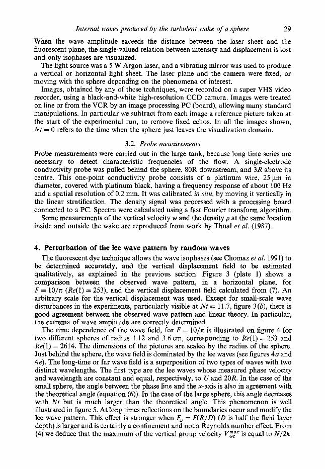
When the wave amplitude exceeds the distance between the laser sheet and the fluorescent plane, the single-valued relation between intensity and displacement is lost and only isophases are visualized.
The light source was a 5 W Argon laser, and a vibrating mirror was used to produce a vertical or horizontal light sheet. The laser plane and the camera were fixed, or moving with the sphere depending on the phenomena of interest.
Images, obtained by any of these techniques, were recorded on a super VHS video recorder, using a black-and-white high-resolution CCD camera. Images were treated on line or from the VCR by an image processing PC (board), allowing many standard manipulations. In particular we subtract from each image a reference picture taken at the start of the experimental run, to remove fixed echos. In all the images shown, Nt = 0 refers to the time when the sphere just leaves the visualization domain.
3.2. Probe measurements Probe measurements were carried out in the large tank, because long time series are necessary to detect characteristic frequencies of the flow. A single-electrode conductivity probe was pulled behind the sphere, 80R downstream, and 3R above its centre. This one-point conductivity probe consists of a platinum wire, 25 pm in diameter, covered with platinum black, having a frequency response of about 100 Hz and a spatial resolution of 0.2 mm. It was calibrated in situ, by moving it vertically in the linear stratification. The density signal was processed with a processing board connected to a PC. Spectra were calculated using a fast Fourier transform algorithm.
Some measurements of the vertical velocity w and the density p at the same location inside and outside the wake are reproduced from work by Thual et al. (1987).
4. Perturbation of the lee wave pattern by random waves The fluorescent dye technique allows the wave isophases (see Chomaz et al. 1991) to
be determined accurately, and the vertical displacement field to be estimated qualitatively, as explained in the previous section. Figure 3 (plate 1) shows a comparison between the observed wave pattern, in a horizontal plane, for F = 1O/n (Re(1) = 253), and the vertical displacement field calculated from (7). An arbitrary scale for the vertical displacement was used. Except for small-scale wave disturbances in the experiments, particularly visible at Nt = 11.7, figure 3 (b), there is good agreement between the observed wave pattern and linear theory. In particular, the extrema of wave amplitude are correctly determined.
The time dependence of the wave field, for F = lo/% is illustrated on figure 4 for two different spheres of radius 1.12 and 3.6 cm, corresponding to Re(1) = 253 and Re(1) = 2614. The dimensions of the pictures are scaled by the radius of the sphere. Just behind the sphere, the wave field is dominated by the lee waves (see figures 4a and 4e). The long-time or far wave field is a superposition of two types of waves with two distinct wavelengths. The first type are the lee waves whose measured phase velocity and wavelength are constant and equal, respectively, to U and 20R. In the case of the small sphere, the angle between the phase line and the x-axis is also in agreement with the theoretical angle (equation (6)). In the case of the large sphere, this angle decreases with Nt but is much larger than the theoretical angle. This phenomenon is well illustrated in figure 5 . At long times reflections on the boundaries occur and modify the lee wave pattern. This effect is stronger when FD = F('(R/D) (D is half the fluid layer depth) is larger and is certainly a confinement and not a Reynolds number effect. From (4) we deduce that the maximum of the vertical group velocity YFfz is equal to N/2k .

30 P. Bonneton, J . M . Chornaz and E. J . Hopjinger
FIGURE 4. Visualization of the lee waves in a horizontal plane at 1z( = 3R below the centre of the sphere for F = 1O/rc. (a-d) Re(1) = 253 (R = 1.12 cm): (a) N t = 0 ; (b) Nt = 11.7; (c) Nt = 23.4; (d) Nt = 35.1. (e-h) Re(1) = 2614 (R = 3.6 cm): (e) Nt = 0 ; ( f ) Nt = 11.7; (g) Nt = 23.4; (h) Nt = 35.1. LW, lee wave; SCC, semicircular concentric wave.
Internal waves produced by the turbulent wake of a sphere 31
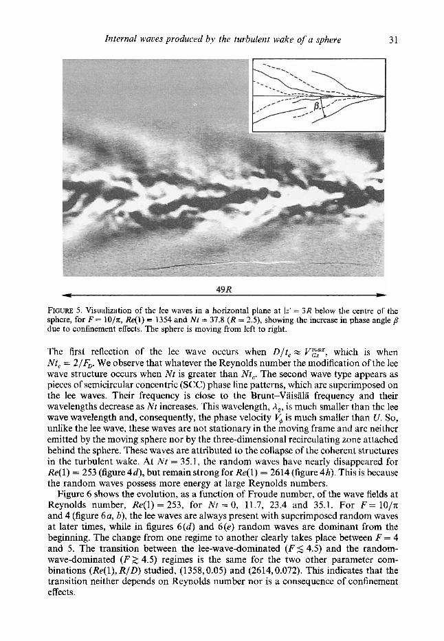
FIGURE 5. Visualization of the lee waves in a horizontal plane at (zI = 3R below the centre of the sphere, for I: = 10/x, Re(1) = 1354 and Nt = 37.8 ( R = 2.5), showing the increase in phase angle B due to confinement effects. The sphere is moving from left to right.
The first reflection of the lee wave occurs when D/ t , z Vgtz , which is when Nt , = 2/F;,. We observe that whatever the Reynolds number the modification of the lee wave structure occurs when Nt is greater than Nt,. The second wave type appears as pieces of semicircular concentric (SCC) phase line patterns, which are superimposed on the lee waves. Their frequency is close to the Brunt-Vaisala frequency and their wavelengths decrease as N t increases. This wavelength, A,, is much smaller than the lee wave wavelength and, consequently, the phase velocity 5 is much smaller than U . So, unlike the lee wave, these waves are not stationary in the moving frame and are neither emitted by the moving sphere nor by the three-dimensional recirculating zone attached behind the sphere. These waves are attributed to the collapse of the coherent structures in the turbulent wake. At Nt = 35.1, the random waves have nearly disappeared for Re( 1) = 253 (figure 4d) , but remain strong for Re(1) = 2614 (figure 4h) . This is because the random waves possess more energy at large Reynolds numbers.
Figure 6 shows the evolution, as a function of Froude number, of the wave fields at Reynolds number, Re(1) = 253, for N t = 0, 11.7, 23.4 and 35.1. For F = 1O/n and 4 (figure 6a, b), the lee waves are always present with superimposed random waves at later times, while in figures 6(d ) and 6(e) random waves are dominant from the beginning. The change from one regime to another clearly takes place between F = 4 and 5. The transition between the lee-wave-dominated (I; 5 4.5) and the random- wave-dominated ( F 2 4.5) regimes is the same for the two other parameter com- binations (Re( l ) , RID) studied, (1358,0.05) and (2614,0.072). This indicates that the transition neither depends on Reynolds number nor is a consequence of confinement effects.

32 P . Bonneton, J . M . Chomaz and E. J . Hopfinger
FIGURE 6. Temporal evolution of the visualization of the internal waves in a horizontal plane Iz] = 3R ( R = 1.12cm) below the centre of the sphere, for Re(1) = 253. Nt = 0, 11.7, 23.4, 35.1. (a) F = 10/n; (b) F = 4; (c) F = 5 ; (d ) F = 20/n; (e) F = 30/n. The scale is 46.5R x 32R.
To determine quantitatively the evolution of the internal wave amplitude as a function of F (figure 7) we measured the density fluctuations outside the turbulent wake (lzl = 3R), at 80R downstream of the sphere. The conductivity probe, towed with the sphere, detects the random waves, but not the lee waves which are stationary in the moving frame. In figure 7 measurements of the maximum lee wave amplitude &,,, at 121 = 3R are also included, determined from particle streak trajectories. It seems that this amplitude evolves like l / F in accordance with the law predicted by the linear theory (equation (9)) which is, for IzI = 3R,
The amplitude of the random waves increases with the Froude number. The wave amplitudes have been measured at fixed x / R and not at fixed Nt. In the experiments the random waves first appear at height z / R = 3 at a distance downstream of x / R = NtF x 1OF. The measurement station x / R = 80 is, therefore, about 4 times further downstream or equal to the position of the first manifestation of the random waves and the wave amplitude might evolve with distance. Nevertheless, according to the measurements of the random wave amplitude by Gilreath & Brandt (1985), this variation in wave amplitude with x / R at a given height z / R is weak. Taking all this into account, the amplitude of the random waves seems, according to figure 7, to increase more like F 2 . We do not have satisfactory theoretical explanation for this dependence on F. The purpose of these measurements was mainly to determine the Froude number

Internal waves produced by the turbulent wake of a sphere 33 1 .o
so R 0.1
0.01
R A
n A*
.. '-..
I A n I
I , , I I I l t 1 1 ,
1 10 F
FIGURE 7. Internal wave amplitude 6, normalized by R, as a function of Froude number, measured at 3R above the centre of the sphere and 80R downstream. Re(1) = 2614; ----, linear theory of lee wave; 0, lee wave amplitude; A, random wave amplitude.
at which the lee waves and random waves are of about equal amplitude. The Reynolds number in figure 7 also varies like Re = Re(1) F, that is, in the range Re E [2350,24950] and the question arises as to whether the amplitude of the random waves depends on Reynolds number. This dependence, if any, should be weak and remains within experimental error. The reason is that the amplitude is determined by the scale of the energy-containing eddies in the wake at onset of collapse, and this scale is proportional to x / R which itself varies with Froude number only, provided the homogeneous wake structure before stratification effects set in, and is independent of Re (a reasonable assumption when Re > lo3). The evolution of the ratio of lee wave energy to random wave energy is difficult to determine because it depends on the Froude number and Nt.
5. Random-wave regime The wavelengths of the random waves A,, measured by flow visualization in a
horizontal plane, for F = lO/n:, 4 and 5 , and Re(1) = 2614, are plotted versus Nt in figure 8. We note that this wavelength decreases roughly like 1/Nt, characteristic of internal waves emitted by a local impulse (see (10)). In a horizontal plane located at lzl = 3R below the wake axis, the horizontal wavelength deduced from (10) is
3n: 1 A2 - - _ 2R sinOcos20N(t-t,)'
We note that the random waves are generated by the same mechanism for F smaller or greater than 4.5. The scatter of data is because waves detected at one time can be emitted at different locations and have different angles of propagation. The random wave field can be interpreted like the superposition of several impulsive waves. In figure 8 we also included the wavelength of coherent waves which appear at Nt w 50. We illustrate these waves in figure 9(c, d) , showing their phase lines at a horizontal plane

34
5 2R
0
B
% a
P. Bonneton, J . M . Chomaz and E. J . HopJinger
A a A A \
-
I I I I I 1 1 1 1 )
10 100 Nt
FIGURE 8. Wavelength of the random waves, normalized by 2R, as a function of Nt. Re(1) = 2614; A, F = 10jn; 0, F = 4; a, F = 5. The solid line shows equation (12).
z = 3R. In figure 9(b), taken at Nt = 35.1, only SCC waves are visible. At later times, Nt = 52.6, figure 9(c), longer-wavelength waves appear with the SCC waves superimposed. At still later times, Nt = 87.7, figure 9(d), the SCC waves have disappeared and fairly regularly structured (coherent waves) remain. Figure 8 shows that their wavelength decreases like (Nt)-l. At present we are not able to interpret the origin and the evolution of these waves.
The coherent structures in the turbulent wake of the sphere generate upward and downward turbulent motions. These motions have a vertical development limited by buoyancy effects and their collapse generates gravity waves. This sequence is illustrated in figure 10, for F = 20/7c. The set of pictures are shadowgraph side views. The non- uniformity of the lighting was corrected and a histogram equalization algorithm was applied in order to make the gravity waves more visible. The coherent structures of the turbulent wake are first affected by stratification at Nt z 2.5, but random wave fringes (phase lines) are first visible on shadowgraph when Nt 2 8. In figure 10, the black and white fringes seen outside the turbulent wake and associated with the waves generated by the collapse of each upward and downward part of the coherent structures are orientated predominantly in the direction of the sphere motion. The growth of the isophase length can be interpreted as the internal wave energy propagation away from the turbulent bursts. The angle 8 between the vertical and isophase lines increases with Nt and reaches, at around Nt x 15, a constant value 8 x 55" close to the theoretical value 8 = arctan 4 2 obtained for an impulsive wave field.
In CBH we have shown that the coherent structures in the turbulent wake occur

Internal waves produced by the turbulent wake of a sphere 35
FIGURE 9. Visualization of the random-coherent waves in a horizontal plane, IzI = 3R (R = 3.6 cm) below the centre of the sphere, for F = 5 and Re(1) = 2614. (a) Nf = 0; (b) Nt = 35.1 ; (cj Nt = 52.6; (d ) Nt = 87.7. CW, coherent wave; SCC, semicircular concentric wave.
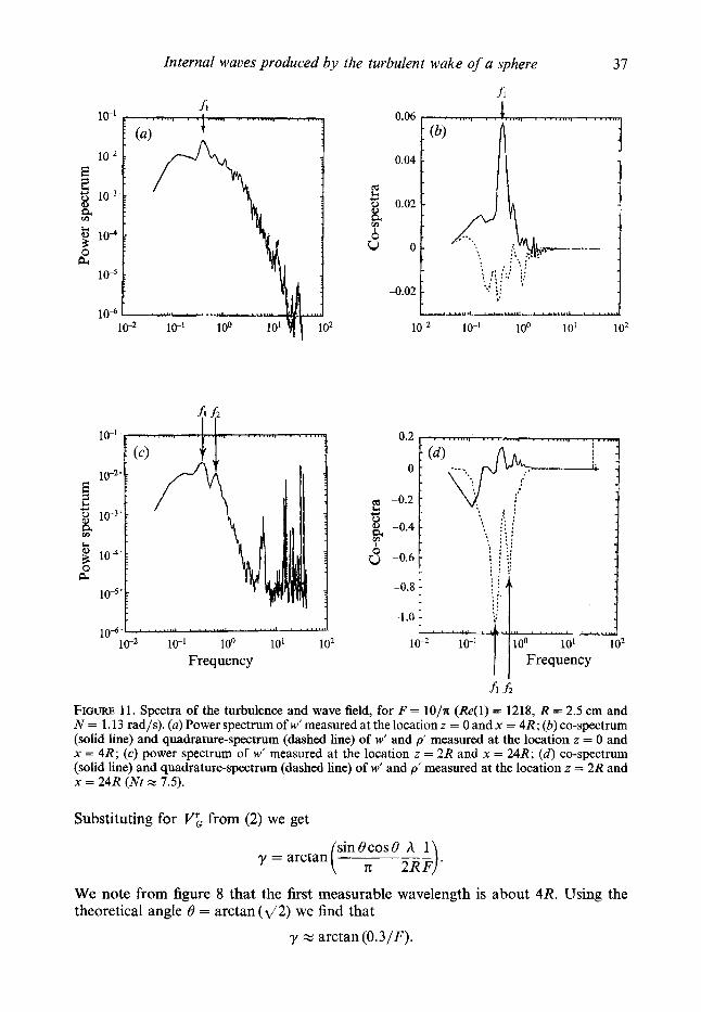
quasi-periodically. In figure 11 (a) we present the spectrum of the vertical velocity fluctuations for F = lO/x, measured with a hot film located at the axis of the turbulent wake at x = 4R (or Nt = 1.2). The spectrum exhibits a significant peak which corresponds to a dimensionless frequency or Strouhal number of 0.2. The quadrature- spectrum between the vertical velocity fluctuations w’ and the density fluctuations p’ at the same location, shown in figure 11 (b), is close to zero and the co-spectrum is large. This implies that w’ and p’ are correlated inside the turbulent region. The same measurements taken outside the wake at lzl = 2R and x = 24R (or N t = 7.5) show the existence of internal waves. In figure 11 ( c ) the frequency spectrum of w’ is plotted and in figure 11 ( d ) the quadrature- and co-spectra between w’ and p’. The fact that the co- spectrum is very large compared to the quadrature-spectrum indicates that w’ and p’ oscillate in phase quadrature as required for internal waves. The spectra presented in figure 11 ( d ) as well as the power spectrum of w‘, figure 11 (c), show two peaks. The lower-frequency peak f, corresponds to the wake instability frequency. This indicates that the turbulent wake periodically generates turbulent bursts which emit gravity waves with the same periodicity. This frequency does not correspond to the wave frequency, but to the modulation frequency of the waves.
The phase velocity of the random waves being much smaller than U, the measured frequency f is related to the wavelength h by h x U/’ From this relation we deduce that the second frequency f, in figures 11 (c) and 11 ( d ) corresponds to the wavelength hJ(2R) = 2.8 at Nt = 7.5. This wavelength is in agreement with those reported in figure 8 measured from visualizations. The relation between frequencies f, and f, is sketched in figure 12.
36 P . Bonneton, J . M . Chomaz and E. J . Hopjnger
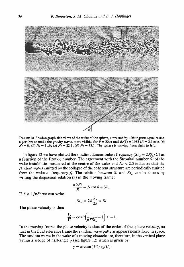
FIGURE 10. Shadowgraph side views of the wake of the sphere, corrected by a histogram equalization algorithm to make the gravity waves more visible, for F = 20/n and Re(1) = 1983 (R = 2.5 cm). (a) Nc = 0; (b) Nt = 11.0; (c) Nt = 22.1; (d) Nt = 33.1. The sphere is moving from right to left.
In figure 13 we have plotted the smallest dimensionless frequency (St, = 2RfJU) as a function of the Froude number. The agreement with the Strouhal number St of the wake instabilities measured at the centre of the wake and Nt < 2.5 indicates that the random waves emitted by the collapse of the coherent structure are periodically emitted from the wake at frequencyf,. The relation between St and St, can be shown by writing the dispersion relation (3) in the moving frame:
-- - Ncos 0+ Uk,. R
If F B 1/7tSt we can write: k, St, = 2R- x St. 27t
The phase velocity is then
V 1 ~ = c o s B -- z-1 . U (7tFst, 1 )
In the moving frame, the phase velocity is thus of the order of the sphere velocity, so that in the fluid reference frame the random wave pattern appears nearly fixed in space. The random waves in the wake of a moving obstacle are, therefore, in the vertical plane within a wedge of half-angle y (see figure 12) which is given by
y = arctan(V&.e,/U).
Internal waves produced by the turbulent wake of a sphere 37
fl 0.06
-0.02
I Y Y U.--l-..U.!--LIl.IU.L
1 o2
cd
u o
10" lo-' 100 10'
I 10"" ' " ' ." . ' ' " " - " ' """'.' ' """' 10-2 lo-' 100 10' 102
Frequency
hf2 FIGURE 11. Spectra of the turbulence and wave field, for F = lO/x (Re(1) = 1218, R = 2.5 cm and N = 1.13 rad/s). (a) Power spectrum of w' measured at the location z = 0 and x = 4R; (b) co-spectrum (solid line) and quadrature-spectrum (dashed line) of w' and p' measured at the location z = 0 and x = 4R; (c) power spectrum of w' measured at the location z = 2R and x = 24R; (d ) co-spectrum (solid line) and quadrature-spectrum (dashed line) of w' and p' measured at the location z = 2R and x = 24R (Nt x 7.5).
Substituting for VL from (2) we get
(sin6';osB _ _ h 1) 2RF y = arctan
We note from figure 8 that the first measurable wavelength is about 4R. Using the theoretical angle 6' = arctan(d2) we find that
y x arctan (0.3/F).

38
3
P. Bonneton, J. M . Chomaz and E. J. Hopfinger
I
+a lee wave Isopycnal lines I- d
----
Random internal wave packets emitted by collapse of coherent structures with frequency f i
Spiral mode
FIGURE 12. Schematic representation of internal waves emitted by the turbulent wake.
0.4 4 1 St
I *
* * *
t
0 L 1 10
F FIGURE 13. Strouhal number as a function of the Froude number. A, St, measured outside the wake
at x / R = 80; *, Strouhal number of the wake instability measured inside the wake at Nt < 2.5.
These waves appear at z / R = 3 around Nt z 10, so
which confirms the validity of this law. This formula is similar to the one obtained by Gilreath & Brandt (1985) through
totally different reasoning. Our coefficient is, however, smaller by a factor of two. We underestimate y because our visualizations overestimate the time of wave appearance and therefore underestimate the first wavelength.

Internal waves produced by the turbulent wake of a sphere 39
6 . Conclusion The appearance of random waves in the lee of moving bodies in stratified fluid is here
clearly demonstrated. Compared with the only previous studies of such random waves by Gilreath & Brandt (1985), who showed that these waves are confined within a wedge of angle 27, we were able to determine the transition from a lee-wave-dominated to a random-wave-dominated regime, visualize the phase lines and relate the properties of the random waves to the structure of the turbulent wake.
Preliminary results on the transition between wave regimes were reported by Chomaz et al. (1991) and Hopfinger et al. (1991). Here we show that the amplitudes of the lee waves decrease as 1/F and that random waves, whose amplitude increases with F, possess a nearly equivalent amplitude when F = 4.5. This transition Froude number value does not seem to depend on Reynolds number, at least not in the range 380 < Re c 30000 studied. More energy is however transferred from the turbulence into the random waves when Re is large, as indicated by figure 4. The observations shown in this figure are also consistent with an energy wedge of the random waves: the waves reach a certain position z at a distance x downstream given by z/x = tany.
From the visualizations of the phase lines it was also possible to determine the wavelengths of the random waves and the angle of energy propagation in the vertical, which is 55" with respect to the z-axis. The wavelength decreases with time according to (Nt)-l , consistent with impulsive wave theory. The waves which arrive first at a position z have a dominant horizontal wavelength A, z 4R. This is much less than the wavelength of the lee waves ( A = 2nFR with F > 4); in the fluid reference frame the phase velocity of the random waves is thus much less than U. The random wave packets are emitted at a frequencyf, corresponding to a Strouhal number close to the Strouhal number of the spiral mode of the wake, St z 0.17. The properties of the random waves, determined from flow visualizations, are confirmed by spectra and co- spectra of velocity and density fluctuations obtained from hot film and conductivity probe measurements.
Although there are indications that the random waves have properties of transient waves, it is hoped that the present results will help in developing more complete models of random waves emitted by turbulent wakes and by turbulence in a stratified medium in general.
This work was financially supported by MCtCo-France and by the DRET, contract number 90-233. Without the help and encouragement of M. Perrier, A. Butet, B. Beaudoin, J. C. Boulay, C. Niclot, M. Niclot, S. Lassus-Pigat and H. Schaffner this work could not have been accomplished.
REFERENCES BONNETON, P., CHOMAZ, J. M. & PERRIER, M. 1990 Interaction between the internal wave field and
the wake emitted behind a moving sphere in a stratified fluid. In Proc. Conf. Engng Turbulence Modelling and Experiments, Dubrovnik, Yugoslavia, (ed. W. Rodi & G. Ganic), pp. 459-466. Elsevier.
CASTRO, 1. P., SNYDER, W. H. & MARSH, C . L. 1983 Stratified flow over three-dimensional ridges. J. Fluid Mech. 135, 261-282.
CHOMAZ, J. M., BONNETON, P., BUTET, A., HOPFINGER, E. J. & PERRIEK, M. 1991 Gravity wave patterns in the wake of a sphere in a stratified fluid. In Proc. Turbulence 89: Organized Structures and Turbulence in Fluid Mech. (ed. M. Lesieur & 0. Mitais), pp. 489-503. Kluwer.
CHOMAZ, J. M., BONNETON, P. & HOPFINGER, E. J. 1993 The structure of the near wake of a sphere moving in a stratified fluid. J . Fluid Mech. 254, 1-21 (referred to herein as CBH).
40 P. Bonneton, J . M . Chomaz and E. J. Hopfinger GARRETT, C. & MUNK, W. 1979 Internal waves in the ocean. Ann. Rev. Fluid Mech. 11, 339-369. GILREATH, H. E. & BRANDT, A. 1985 Experiments on the generation of internal waves in a stratified
HANAZAKI, H. 1988 A numerical study of three-dimensional stratified flow past a sphere. J. Fluid
HARTMAN, R. J. & LEWIS, H. W. 1972 Wake collapse in a stratified fluid: linear treatment. J. Fluid
HOPFINGER, E. J., F L ~ R , J. B., CHOMAZ, J. M. & BONNETON, P. 1991 Internal waves generated by a
HUNT, J. C. R. & SNYDER, W. H. 1980 Experiments on stably and neutrally stratified flow over a
JANOWITZ, G. S. 1984 Lee waves in three-dimensional stratified flow. J . Fluid Mech. 148, 97-108. LIGHTHILL, M. J. 1978 Waves in Fluids. Cambridge University Press. LIN, J. T. & PAO, Y. H. 1979 Wakes in stratified fluids. Ann. Rev. Fluid Mech. 11, 317-338. LIN, Q., LINDBERG, W. R., BOYER, D. L. & FERNANDO, H. J. S. 1992 Stratified flow past a sphere.
MAKAROV, S. A. & CHASHECHKIN, Yu. D. 1981 Apparent internal waves in a fluid with exponential
MILES, J. W. 1971 Internal waves generated by a horizontally moving source. Geophys. Fluid Dyn.
PJ~AT, K. S . & STEVENSON, T. N. 1975 Internal waves around a body moving in a compressible
SCHOOLEY, A. H. & STEWART, R. W. 1963 Experiments with a self-propelled body submerged in a
SMITH, R. B. 1980 Linear theory of stratified hydrostatic flow past an isolated mountain. Tellus 32,
SMITH, R. B. 1989 Hydrostatic airflow over mountains. Adv. Geophys. 31, 1 4 1 . SMOLARKIEWICZ, P. K. & ROTUNNO, R. 1989 Low Froude number flow past three-dimensional
obstacles. Part I: Baroclinically generated lee vortices. J. Atmos. Sci. 46, 11541 164. STEVENSON, T. N. 1973 The phase configuration of internal waves around a body moving in a density
stratified fluid. J . Fluid Mech. 60, 759-767. THUAL, O., BUTET, A., PERRIER, M. & HOPFINGER, E. 1987 Sillage d’une sphkre en milieu stratifie.
Rapport DRET 85/105. VOISIN, B. 1991 a Rayonnement des ondes internes de gravid. Application aux corps en mouvement.
PhD thesis, Paris 6 University. VOISIN, B. 1991 b Internal wave generation in uniformly stratified fluids. Part 1. Green’s function and
point sources. J . Fluid Mech. 231, 439-480. VOISIN, B. 1993 Internal wave generation in uniformly stratified fluids. Part 2. Moving point sources.
J . Fluid Mech. (submitted). Wu, J. 1969 Mixed region collapse with internal wave generation in a density-stratified medium.
J . Fluid Mech. 35, 531-544. ZAVOL’SKII, N. A. & ZAITSEV, A. A. 1984 Development of internal waves generated by a
concentrated pulse source in an infinite uniformly stratified fluid. J. Appl. Mech. Tech. Phys. 25,
fluid. AIAA J . 23, 693-700.
Mech. 192, 393419.
Mech. 51, 613418.
moving sphere and its wake in a stratified fluid. Exps Fluids 11, 255-261.
model three-dimensional hill. J. Fluid Mech. 96, 671-704.
J . Fluid Mech. 240, 315-354.
density distribution. J. Appl. Mech. Techn. Phys. 22, 772-779.
2, 63-87.
density-stratified fluid. J. Fluid Mech. 70, 673-688.
fluid with a vertical density gradient. J . Fluid Mech. 15, 83-96.
348-364.
862-867.


![Flight-Test Measurement of the Aero-Optical Environment of ...sgordeye/Papers/AIAAJv54no9_2016-AOHelicopter.pdfeffects of viscous and turbulent diffusion. In [15], these wake modeling](https://img.pdfslide.us/doc/110x75/5f22809f67a4da775438d103/flight-test-measurement-of-the-aero-optical-environment-of-sgordeyepapersaiaajv54no92016-.jpg)