Embed Size (px)
Citation preview
P/N: A-1076/A-1281, Rev. 2.1 Issue Date: April 10, 2018
Supersedes: A-1076/A-1281, Rev. 2
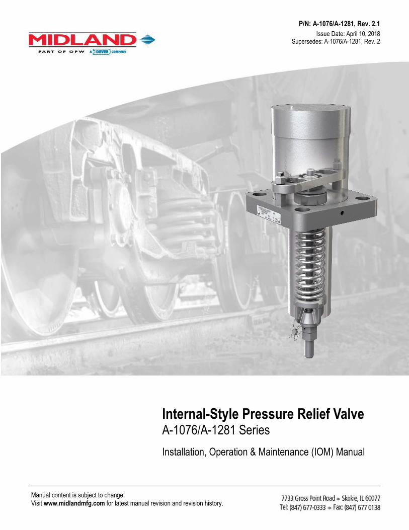
Internal-Style Pressure Relief Valve A-1076/A-1281 SeriesInstallation, Operation & Maintenance (IOM) Manual
Manual content is subject to change. Visit www.midlandmfg.com for latest manual revision and revision history.
A-1076/A-1281, Rev. 2.1
Page 2 of 40
Manual content is subject to change. Visit midlandmfg.com for latest manual revision and revision history.
Table of Contents " Regulations and Safety Requirements ............................................................................................ 3
Regulations ............................................................................................................................. 3
Safety Warnings and Precautions ........................................................................................... 3
: Introduction ..................................................................................................................................... 6
Valve Details ........................................................................................................................... 6
@ Valve Installation .......................................................................................................................... 10
Installation Procedure and Recommended Tools .................................................................. 10
Leak Inspection ..................................................................................................................... 12
Valve Operation Notes and Precautions ............................................................................... 12
J Valve Qualification ........................................................................................................................ 13
Valve Disassembly and Recommended Tools ...................................................................... 13
Component Inspection .......................................................................................................... 19
Valve Reassembly and Recommended Tools ....................................................................... 25
Testing Process .................................................................................................................... 30
Valve-Setting Adjustment Procedure .................................................................................... 32
Post-Test Procedure ............................................................................................................. 34
T Routine Maintenance .................................................................................................................... 35
Routine Repair Procedure..................................................................................................... 35
V Emergency Response for Leaking Valve ...................................................................................... 39
Follow All Routine Maintenance Procedures ......................................................................... 39
A-1076/A-1281, Rev. 2.1
Page 3 of 40
Manual content is subject to change. Visit midlandmfg.com for latest manual revision and revision history.
1 Regulations and Safety Requirements 1.1 Regulations Midland internal-style pressure relief valves are used in contact with a variety of products, many of which are hazardous materials and could cause serious injury or damage if mishandled. The acceptance and transportation of products are regulated by the DOT and AAR in the U.S.A., and in Canada by CTC and Transport Canada. Regulations of other governmental bodies must be complied with for stationary and mobile applications. All personnel should be familiar with and follow these regulations. Nothing in these instructions is intended to conflict with or supersede these regulations. The information in this document was gathered from knowledgeable sources. However, Midland Manufacturing makes no representations or guarantees about its accuracy or completeness, and assumes no liability for this information.
Specifications are subject to change without notice.
This valve should only be installed, operated and maintained by qualified personnel. Read these instructions carefully before proceeding.
Operation of the valve must conform to all applicable specifications from TC, AAR, DOT, CFR (Parts 173.31, 174.67, etc.) and other governmental bodies, along with the operating instructions of your company.
1.2 Safety Warnings and Precautions Please carefully read each of the following warnings and cautions prior to performing any work.
WARNING: Toxic Hazard. Always use extreme caution and proper equipment when involved with hazardous materials. To avoid exposure to toxic or hazardous materials, make sure the tank car is empty and clean, and that the work area is free of hazardous chemicals before removing or installing any valve.
• Wear protective clothing and equipment suitable for withstanding the materials to which you may be exposed
• Position yourself on the upwind side of the valve when possible • Work in a well-ventilated area • Work with a partner who can help you in the event of an emergency • Follow approved safety precautions for hazardous or toxic materials • Obtain MSDS sheets for all the commodities used with the associated valve
WARNING: Spring-Loaded Assembly. During valve-spring disassembly, the valve contains springs under load. DO NOT attempt to disassemble the valve without first reading these instructions or injury may result. Spring pressure must be adjusted to the minimum and a bench clamp or press used for disassembly.
WARNING: Spring-Loaded Assembly: These internal-style pressure relief valves are spring-loaded assemblies with a large amount of stored potential energy in the spring. Handle with care to avoid damage to the valve stem, which could result in breakage and ejected piece parts.
When assembling or disassembling the valve, DO NOT position oneself directly in front of the spring and stem. Instead, position oneself to the side away from the valve. Unexpected component failure of the valve stem or spring breakage may cause a sudden energy release that can discharge component parts a short distance in an uncontrolled manner. Personal injury may be a result.
WARNING
WARNING
WARNING
A-1076/A-1281, Rev. 2.1
Page 4 of 40
Manual content is subject to change. Visit midlandmfg.com for latest manual revision and revision history.
CAUTION: Valve Leakage. Improper valve-tongue seating in the flange groove, loose nuts and damaged gaskets may result in leaks at the valve-mounting joint.
CAUTION: Incorrect Spring Setting. Never adjust the spring compression of a valve while it is mounted on the vessel cover plate or incorrect settings may result.
CAUTION: Valve/Seat Damage. With spring pressure removed from the valve stem, the stem can easily shift, allowing the sealing edges of the stem to contact metal surfaces or to improperly contact the valve seat. When laying the valve onto the workbench, keep a constant lifting force on the valve stem above the spring to keep the valve seated. Lay the assembly down on its side carefully and immediately grasp the opposite (short) end of the stem to prevent valve/seat damage.
CAUTION: Valve-Stem Eccentricity. Excessive valve-stem eccentricity will cause binding that can result in high start-to-discharge pressure settings, reduced valve capacity and/or low vapor-tight pressures.
CAUTION: Valve-Stem Failure. Cracks and corrosion of pressure relief valve stems can result in stem failure and uncontrolled venting.
CAUTION: Valve-Stem Straightening. Straightening of the stem by bending it in a press may result in the buildup of uneven stresses in the stem, which may result in valve malfunction.
CAUTION: Valve-Spring Failure. Defects in coil springs, such as cracks and corrosion pits, can act as stress concentrators. Failure to detect these defects can result in coil-spring breakage and uncontrolled valve venting.
CAUTION: Deficient Valve Travel. Coil springs that have taken a “set,” resulting in an undersized free-height, will not allow the valve to open fully. The spring should not be bowed more than 1/4" when in the assembled position. Bowing in excess of this amount can cause the spring to rub against the inside wall of the nozzle or guide tube and adversely affect the pressure settings. If any of the defects mentioned above are observed, the spring cannot be repaired and must be replaced.
CAUTION
CAUTION
CAUTION
CAUTION
CAUTION
CAUTION
CAUTION
CAUTION
A-1076/A-1281, Rev. 2.1
Page 5 of 40
Manual content is subject to change. Visit midlandmfg.com for latest manual revision and revision history.
CAUTION: Valve Sticking. If the spring guide binds in the guide tube (nozzle), the valve may stick in the open position or be prevented from opening. Always ensure free travel of the spring guide before reassembling the valve.
CAUTION: Tongue Damage. A damaged valve tongue may prevent proper sealing on the tank-car mounting and result in leakage of the tank contents.
CAUTION: Field Repair. The repair procedure for leaking valves in the field is intended only as a temporary repair to get the car to an unloading destination. Once the product is unloaded and pressure is relieved, the valve should be removed for a complete inspection and requalification.
CAUTION: O-Ring Replacement. Conducting this procedure may be hazardous (depending on the commodity in the tank car). Maintenance personnel should be carefully trained before being permitted to perform the procedure below on a pressure relief valve mounted on a pressurized tank.
CAUTION: Valve Discharge. When the O-ring retainer cap is raised up, there will be a significant amount of product discharging. Have emery paper, a cleaning cloth, replacement O-ring retainer cap (with epoxied O-rings) and silicone grease (typically Kytox GPL204 or equivalent) close at hand. Use a wheel puller, or two (2) screwdrivers 180° apart, to quickly dislodge the O-ring retainer.
CAUTION
CAUTION
CAUTION
CAUTION
CAUTION
A-1076/A-1281, Rev. 2.1
Page 6 of 40
Manual content is subject to change. Visit midlandmfg.com for latest manual revision and revision history.
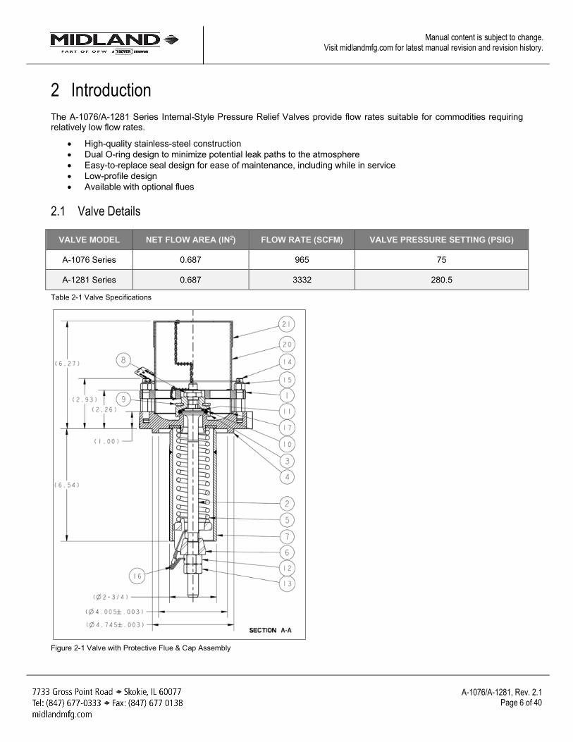
2 Introduction The A-1076/A-1281 Series Internal-Style Pressure Relief Valves provide flow rates suitable for commodities requiring relatively low flow rates.
• High-quality stainless-steel construction • Dual O-ring design to minimize potential leak paths to the atmosphere • Easy-to-replace seal design for ease of maintenance, including while in service • Low-profile design • Available with optional flues
2.1 Valve Details
VALVE MODEL NET FLOW AREA (IN2) FLOW RATE (SCFM) VALVE PRESSURE SETTING (PSIG)
A-1076 Series 0.687 965 75
A-1281 Series 0.687 3332 280.5
Table 2-1 Valve Specifications
Figure 2-1 Valve with Protective Flue & Cap Assembly
A-1076/A-1281, Rev. 2.1
Page 7 of 40
Manual content is subject to change. Visit midlandmfg.com for latest manual revision and revision history.
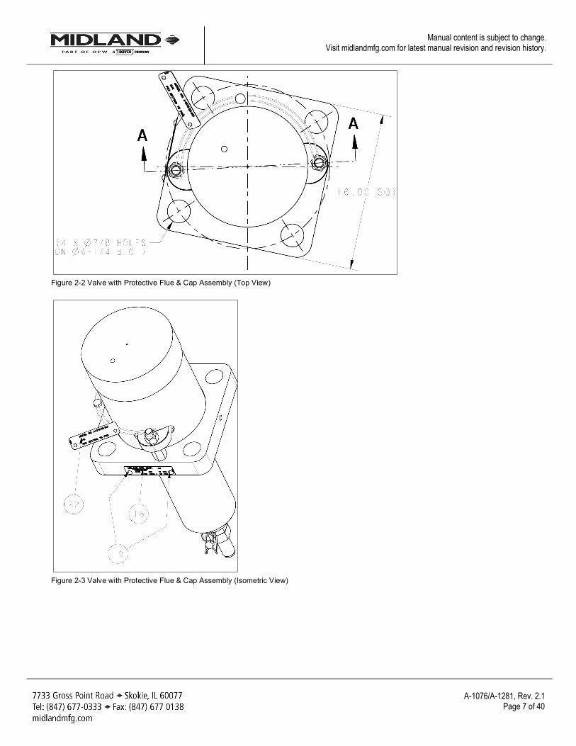
Figure 2-2 Valve with Protective Flue & Cap Assembly (Top View)
Figure 2-3 Valve with Protective Flue & Cap Assembly (Isometric View)
A-1076/A-1281, Rev. 2.1
Page 8 of 40
Manual content is subject to change. Visit midlandmfg.com for latest manual revision and revision history.
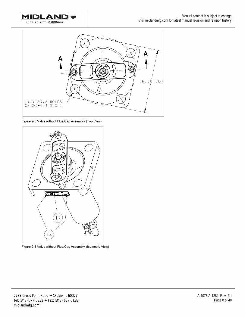
Figure 2-5 Valve without Flue/Cap Assembly (Top View)
Figure 2-6 Valve without Flue/Cap Assembly (Isometric View)
A-1076/A-1281, Rev. 2.1
Page 9 of 40
Manual content is subject to change. Visit midlandmfg.com for latest manual revision and revision history.
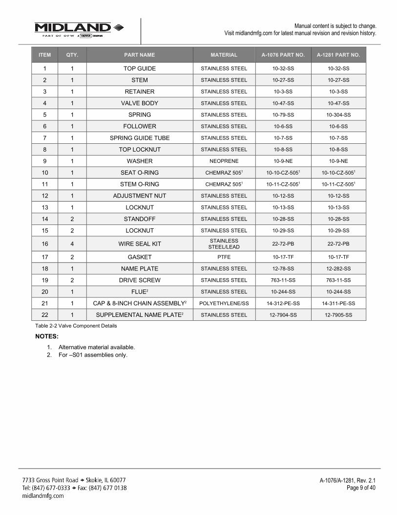
ITEM QTY. PART NAME MATERIAL A-1076 PART NO. A-1281 PART NO.
1 1 TOP GUIDE STAINLESS STEEL 10-32-SS 10-32-SS
2 1 STEM STAINLESS STEEL 10-27-SS 10-27-SS
3 1 RETAINER STAINLESS STEEL 10-3-SS 10-3-SS
4 1 VALVE BODY STAINLESS STEEL 10-47-SS 10-47-SS
5 1 SPRING STAINLESS STEEL 10-79-SS 10-304-SS
6 1 FOLLOWER STAINLESS STEEL 10-6-SS 10-6-SS
7 1 SPRING GUIDE TUBE STAINLESS STEEL 10-7-SS 10-7-SS
8 1 TOP LOCKNUT STAINLESS STEEL 10-8-SS 10-8-SS
9 1 WASHER NEOPRENE 10-9-NE 10-9-NE
10 1 SEAT O-RING CHEMRAZ 5051 10-10-CZ-5051 10-10-CZ-5051
11 1 STEM O-RING CHEMRAZ 5051 10-11-CZ-5051 10-11-CZ-5051
12 1 ADJUSTMENT NUT STAINLESS STEEL 10-12-SS 10-12-SS
13 1 LOCKNUT STAINLESS STEEL 10-13-SS 10-13-SS
14 2 STANDOFF STAINLESS STEEL 10-28-SS 10-28-SS
15 2 LOCKNUT STAINLESS STEEL 10-29-SS 10-29-SS
16 4 WIRE SEAL KIT STAINLESS STEEL/LEAD 22-72-PB 22-72-PB
17 2 GASKET PTFE 10-17-TF 10-17-TF
18 1 NAME PLATE STAINLESS STEEL 12-78-SS 12-282-SS
19 2 DRIVE SCREW STAINLESS STEEL 763-11-SS 763-11-SS
20 1 FLUE2 STAINLESS STEEL 10-244-SS 10-244-SS
21 1 CAP & 8-INCH CHAIN ASSEMBLY2 POLYETHYLENE/SS 14-312-PE-SS 14-311-PE-SS
22 1 SUPPLEMENTAL NAME PLATE2 STAINLESS STEEL 12-7904-SS 12-7905-SS
Table 2-2 Valve Component Details
NOTES: 1. Alternative material available. 2. For –S01 assemblies only.
A-1076/A-1281, Rev. 2.1
Page 10 of 40
Manual content is subject to change. Visit midlandmfg.com for latest manual revision and revision history.
3 Valve Installation New valves are tested, adjusted and sealed at Midland. If a new valve has been left in its original packaging, is undamaged and is not more than six (6) months old, it may be installed on a tank car without retesting or recalibration.
Prior to installation, ensure that the valve remains clean and the gasket-sealing surfaces are not damaged.
3.1 Installation Procedure and Recommended Tools
SAE Wrench Component(s)/Description 1-1/4” Mounting Stud Nuts Other Tools, Supplies, and Equipment: Torque Wrench Mounting Stud Nuts Wire Brush To Clean the Valves and Cover-Plate Sealing Surfaces Lint-Free Cloth To Clean Sealing Surfaces
Table 3-1 Recommended Tools for Valve Assembly
NOTICE: Consult gasket manufacturer and Midland Manufacturing for torque requirements as max torque may vary by valve model. Do not exceed 200 ft-lb.
3.1.1 Remove the old valve and then insert a soft rubber plug into the tank opening to prevent debris from entering the tank during cleaning of the valve-mounting groove and studs on the manway cover plate.
3.1.2 Using a wire brush, brush the threads of the mounting studs to remove rust or scale. Nuts should move freely on clean studs. Studs should not exhibit excessive corrosion. Inspect threads for any sign of excessive wear, corrosion, pitting or other defects. If any are found, the part is rejectable and should be replaced.
3.1.3 Remove and discard all used gasket material.
CAUTION: Groove Damage. In order to avoid groove damage, do not scratch the metal in the bottom of the groove when removing the old gasket.
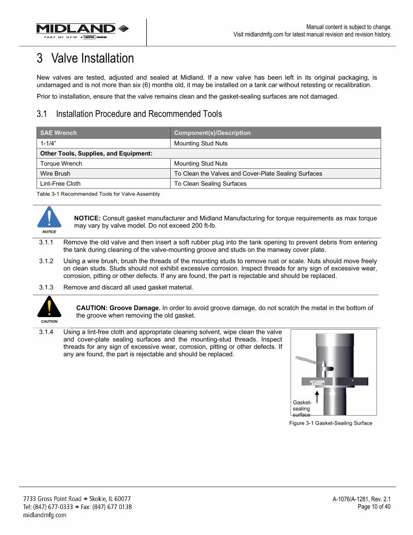
3.1.4 Using a lint-free cloth and appropriate cleaning solvent, wipe clean the valve and cover-plate sealing surfaces and the mounting-stud threads. Inspect threads for any sign of excessive wear, corrosion, pitting or other defects. If any are found, the part is rejectable and should be replaced.
Figure 3-1 Gasket-Sealing Surface
NOTICE
CAUTION
Gasket-sealing surface
A-1076/A-1281, Rev. 2.1
Page 11 of 40
Manual content is subject to change. Visit midlandmfg.com for latest manual revision and revision history.
3.1.5 For tongue-and-groove mountings, examine the sides of the groove. The valve tongue fits tightly into the groove, any peening-over of the edges of the groove may make it difficult to properly fit the valve tongue into the groove. If the sides of the groove are peened over, make corrections to meet the AAR’s groove tolerances.
3.1.6 Install the new gasket. Ensure it is fully seated. When a groove gasket is fully seated, 1/16" of free space should remain above the gasket to permit locating and entry of the valve tongue.
CAUTION: Do not use a sharp tool to press the new gasket into place or gasket damage may result.
3.1.7 For tongue-and-groove mountings, inspect the tongue of a new, reconditioned or retested valve by running your fingernail around its inner and outer edges to check for damage. The tongue dimensions have diameter tolerances of ±0.003", thus any excess material on these diameters will make it difficult to fit the tongue into the groove. If the tongue is peened over, remove excess material to meet AAR tongue tolerances.
CAUTION: To prevent groove damage, do not install a valve having damaged sealing surfaces.
3.1.8 Remove the rubber plug from the cover plate.
3.1.9 Position the valve gently into the mounting. Align the body holes over the studs and lower the valve while positioning the valve tongue in the cover-plate groove.
CAUTION: Tongue Not in Cover-Plate Groove. Verify that the valve tongue fits into the cover-plate groove. It must be so engaged before continuing with the next step or valve damage may result.
CAUTION
CAUTION
CAUTION
A-1076/A-1281, Rev. 2.1
Page 12 of 40
Manual content is subject to change. Visit midlandmfg.com for latest manual revision and revision history.
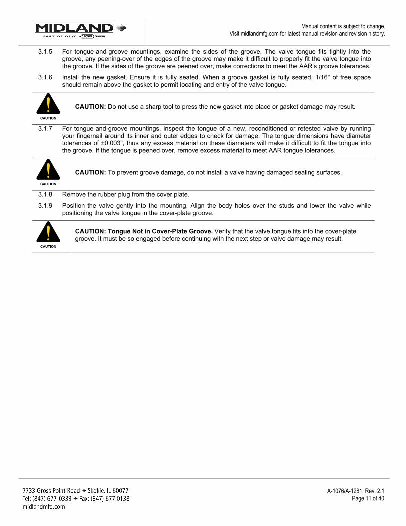
3.1.10 Install the nuts and tighten them in 1/3-torque increments in a diagonally alternating sequence, as shown in Figure 3-2. Consult gasket manufacturer for recommended torque requirements.
NOTICE: This is for installation to the car, so the pattern is on the outside bolts.
CAUTION: Uneven Gasket Compression. Do not over-tighten the nuts on one side of the valve as this may tilt the valve and result in uneven gasket compression.
TIP: Use a 1-1/4” wrench to tighten mounting nuts. Do not exceed 200 ft-lb.
Figure 3-2 Tightening Sequence
3.2 Leak Inspection 3.2.1 Test all newly installed valves to conform to car-owner specifications. No leaks should be present.
WARNING: Valve Leakage. Improper valve-tongue seating in the flange groove, loose nuts and damaged gaskets may result in leaks at the valve-mounting joint.
3.3 Valve Operation Notes and Precautions
CAUTION: Incorrect Setting. Never adjust the spring compression of a valve while it is mounted on the vessel cover plate or incorrect settings may result.
NOTICE
CAUTION
WARNING
CAUTION
1
2
3
4
A-1076/A-1281, Rev. 2.1
Page 13 of 40
Manual content is subject to change. Visit midlandmfg.com for latest manual revision and revision history.
4 Valve Qualification
NOTICE: To ensure best practice and consistency of your qualification procedure, O-rings, gaskets and wire seals should always be replaced.
Nuts, washers and studs must be closely inspected before re-use or replaced regularly.
Valve components such as the top guide, stem, retainer, body and spring must be thoroughly inspected.
4.1 Valve Disassembly and Recommended Tools
SAE Wrenches Component(s)/Description Item #
9/16” Locknut and Standoffs 15, 14 15/16” Top Locknut (Retainer) 8 1” Flats on O-Ring Retainer 3 15/16” Locknuts 12, 13 Other Tools, Supplies, and Equipment: Silicone Grease (typically Kytox GPL204 or equivalent) Emery Paper (400 grit, cut in 1” strips) Lint-free Cloth Torque Wrenches (0-200 ft-lb) Wire Brush Two-Arm Puller Non-Scratching Tool to Remove O-Rings Screwdrivers
Table 4-1 Recommended Tools for Valve Disassembly
NOTICE: Valve disassembly should only be done by trained personnel with access to the proper machines, tools, procedures and personal-protective equipment (PPE).
CAUTION: Spring-loaded Assembly. During valve-spring disassembly, the valve contains springs under load. DO NOT attempt to disassemble the valve without first reading these instructions or injury may result. Spring pressure must be adjusted to the minimum and a bench clamp or press used for disassembly.
NOTICE
NOTICE
CAUTION
A-1076/A-1281, Rev. 2.1
Page 14 of 40
Manual content is subject to change. Visit midlandmfg.com for latest manual revision and revision history.
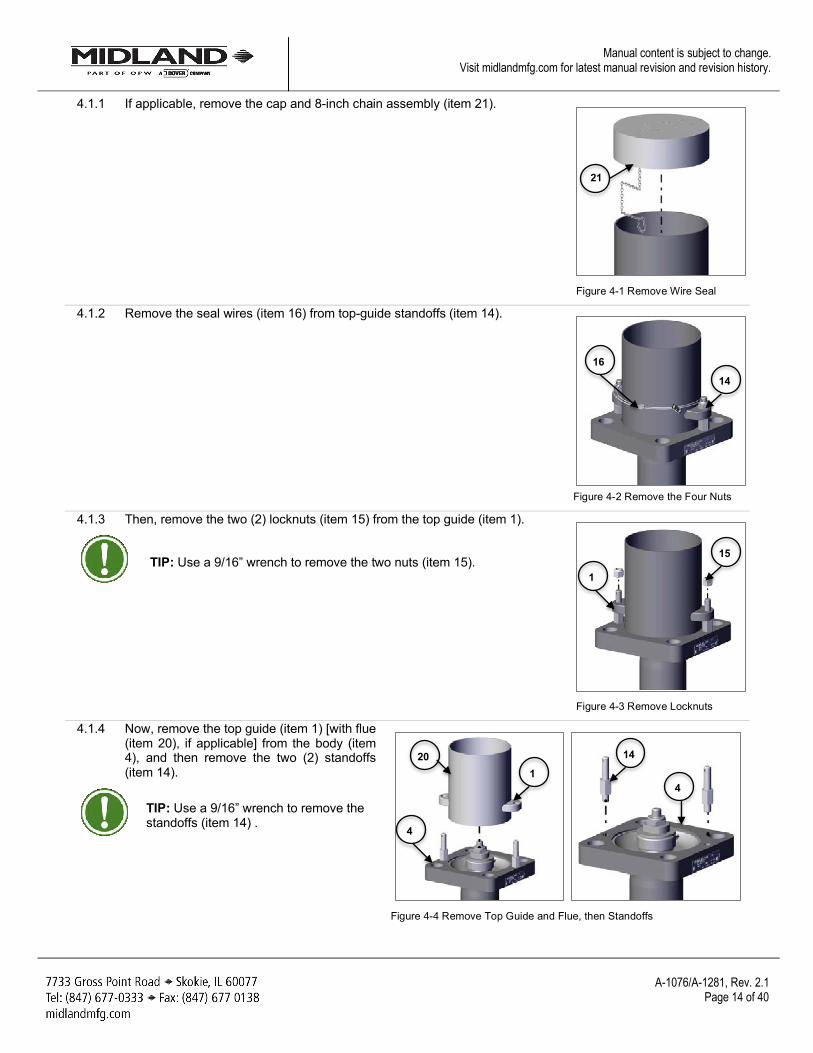
4.1.1 If applicable, remove the cap and 8-inch chain assembly (item 21).
Figure 4-1 Remove Wire Seal
4.1.2 Remove the seal wires (item 16) from top-guide standoffs (item 14).
Figure 4-2 Remove the Four Nuts
4.1.3 Then, remove the two (2) locknuts (item 15) from the top guide (item 1).
TIP: Use a 9/16” wrench to remove the two nuts (item 15).
Figure 4-3 Remove Locknuts
4.1.4 Now, remove the top guide (item 1) [with flue (item 20), if applicable] from the body (item 4), and then remove the two (2) standoffs (item 14).
TIP: Use a 9/16” wrench to remove the standoffs (item 14) .
Figure 4-4 Remove Top Guide and Flue, then Standoffs
16
14
21
15
1
4
20 1
14
4
A-1076/A-1281, Rev. 2.1
Page 15 of 40
Manual content is subject to change. Visit midlandmfg.com for latest manual revision and revision history.
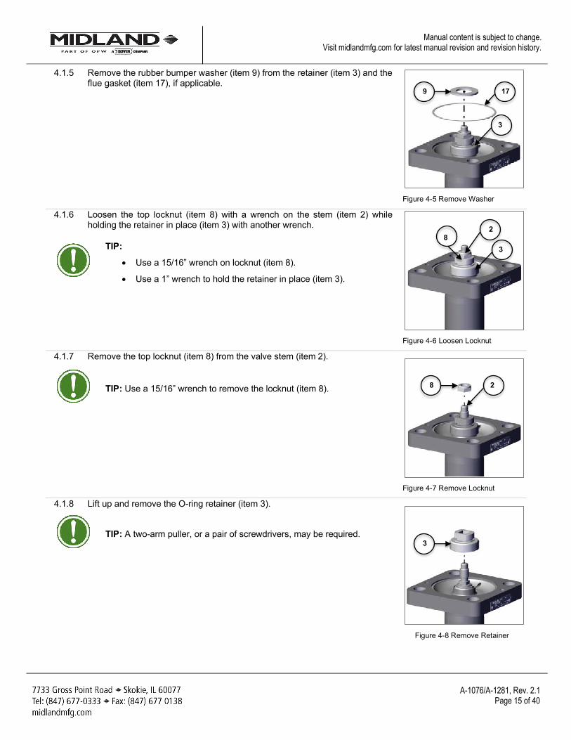
4.1.5 Remove the rubber bumper washer (item 9) from the retainer (item 3) and the flue gasket (item 17), if applicable.
Figure 4-5 Remove Washer
4.1.6 Loosen the top locknut (item 8) with a wrench on the stem (item 2) while holding the retainer in place (item 3) with another wrench.
TIP:
• Use a 15/16” wrench on locknut (item 8).
• Use a 1” wrench to hold the retainer in place (item 3).
Figure 4-6 Loosen Locknut
4.1.7 Remove the top locknut (item 8) from the valve stem (item 2).
TIP: Use a 15/16” wrench to remove the locknut (item 8).
Figure 4-7 Remove Locknut
4.1.8 Lift up and remove the O-ring retainer (item 3).
TIP: A two-arm puller, or a pair of screwdrivers, may be required.
Figure 4-8 Remove Retainer
3
9 17
3 8
2
8 2
3
A-1076/A-1281, Rev. 2.1
Page 16 of 40
Manual content is subject to change. Visit midlandmfg.com for latest manual revision and revision history.
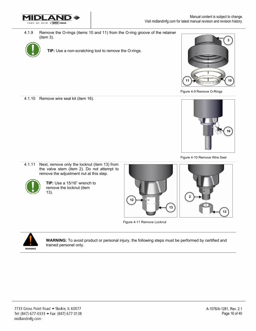
4.1.9 Remove the O-rings (items 10 and 11) from the O-ring groove of the retainer (item 3).
TIP: Use a non-scratching tool to remove the O-rings.
Figure 4-9 Remove O-Rings
4.1.10 Remove wire seal kit (item 16).
Figure 4-10 Remove Wire Seal
4.1.11 Next, remove only the locknut (item 13) from the valve stem (item 2). Do not attempt to remove the adjustment nut at this step.
TIP: Use a 15/16” wrench to remove the locknut (item 13).
Figure 4-11 Remove Locknut
WARNING: To avoid product or personal injury, the following steps must be performed by certified and trained personel only.
WARNING
11 10
3
16
13
2 12
13
A-1076/A-1281, Rev. 2.1
Page 17 of 40
Manual content is subject to change. Visit midlandmfg.com for latest manual revision and revision history.
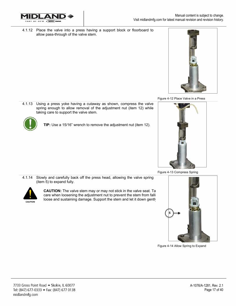
4.1.12 Place the valve into a press having a support block or floorboard to allow pass-through of the valve stem.
Figure 4-12 Place Valve in a Press
4.1.13 Using a press yoke having a cutaway as shown, compress the valve spring enough to allow removal of the adjustment nut (item 12) while taking care to support the valve stem.
TIP: Use a 15/16” wrench to remove the adjustment nut (item 12).
Figure 4-13 Compress Spring
4.1.14 Slowly and carefully back off the press head, allowing the valve spring (item 5) to expand fully.
CAUTION: The valve stem may or may not stick in the valve seat. Take care when loosening the adjustment nut to prevent the stem from falling loose and sustaining damage. Support the stem and let it down gently.
Figure 4-14 Allow Spring to Expand
CAUTION
5
A-1076/A-1281, Rev. 2.1
Page 18 of 40
Manual content is subject to change. Visit midlandmfg.com for latest manual revision and revision history.
4.1.15 Remove the valve from the press, taking care to lift it by the valve stem (item 2). This will prevent the stem from falling out of the valve body.
WARNING: Valve/Seat Damage. With spring pressure removed from the valve stem, the stem can easily shift, allowing the sealing edges of the stem to contact metal surfaces or to improperly contact the valve seat. When laying the valve onto the workbench, keep a constant lifting force on the valve stem above the spring to keep the valve seated. Lay the assembly down on its side carefully and immediately grasp the opposite (short) end of the stem to prevent valve/seat damage.
4.1.16 Lay the valve on a bench and place a properly sized wooden block beneath the short end of the valve stem to prevent it from dropping and damaging the valve seat.
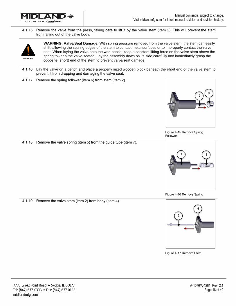
4.1.17 Remove the spring follower (item 6) from stem (item 2).
Figure 4-15 Remove Spring Follower
4.1.18 Remove the valve spring (item 5) from the guide tube (item 7).
Figure 4-16 Remove Spring
4.1.19 Remove the valve stem (item 2) from body (item 4).
Figure 4-17 Remove Stem
WARNING
6 2
5 7
2
4
A-1076/A-1281, Rev. 2.1
Page 19 of 40
Manual content is subject to change. Visit midlandmfg.com for latest manual revision and revision history.
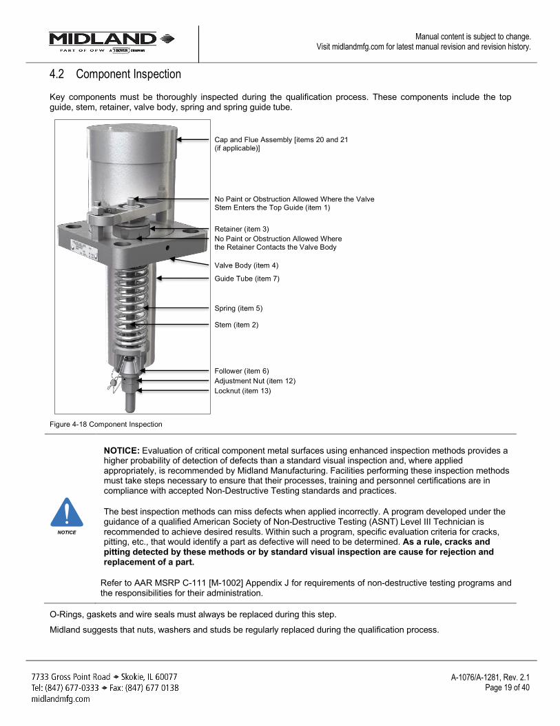
4.2 Component Inspection Key components must be thoroughly inspected during the qualification process. These components include the top guide, stem, retainer, valve body, spring and spring guide tube.
Figure 4-18 Component Inspection
NOTICE: Evaluation of critical component metal surfaces using enhanced inspection methods provides a higher probability of detection of defects than a standard visual inspection and, where applied appropriately, is recommended by Midland Manufacturing. Facilities performing these inspection methods must take steps necessary to ensure that their processes, training and personnel certifications are in compliance with accepted Non-Destructive Testing standards and practices.
The best inspection methods can miss defects when applied incorrectly. A program developed under the guidance of a qualified American Society of Non-Destructive Testing (ASNT) Level III Technician is recommended to achieve desired results. Within such a program, specific evaluation criteria for cracks, pitting, etc., that would identify a part as defective will need to be determined. As a rule, cracks and pitting detected by these methods or by standard visual inspection are cause for rejection and replacement of a part.
Refer to AAR MSRP C-111 [M-1002] Appendix J for requirements of non-destructive testing programs and the responsibilities for their administration.
O-Rings, gaskets and wire seals must always be replaced during this step.
Midland suggests that nuts, washers and studs be regularly replaced during the qualification process.
NOTICE
Spring (item 5)
Cap and Flue Assembly [items 20 and 21 (if applicable)]
Stem (item 2)
Guide Tube (item 7)
Valve Body (item 4)
No Paint or Obstruction Allowed Where the Valve Stem Enters the Top Guide (item 1)
Retainer (item 3) No Paint or Obstruction Allowed Where the Retainer Contacts the Valve Body
Locknut (item 13) Adjustment Nut (item 12) Follower (item 6)
A-1076/A-1281, Rev. 2.1
Page 20 of 40
Manual content is subject to change. Visit midlandmfg.com for latest manual revision and revision history.
NOTICE: Procedures may not cover all conditions encountered in the field. Therefore, it is the responsibility of the repair agency to obtain approval from Midland for inspection, evaluation, repair and maintenance procedures not covered herein.
Evaluation of critical component metal surfaces of the valves after cleaning, inspection and specialized testing performed by agencies other than the repair facility are the responsibility of the repair facility.
Where numerical tolerances cannot be provided, the disposition of the internal integrity and surface quality of parts is under the jurisdiction of the repair facility and dependent on its experience and judgment.
NOTICE: Without consent from the valve manufacturer or car owner, repair work is limited to cleaning and polishing. See AAR M1002, Paragraph A3.11.1 of the Tank-Car Specifications.
WARNING: Machining Not Allowed. Without consent from the valve manufacturer or car owner, machining, grinding, welding or other alterations to the valve seat or stem seat is not allowed per AAR M1002, Paragraph A3.11.1 of the Tank-Car Specifications.
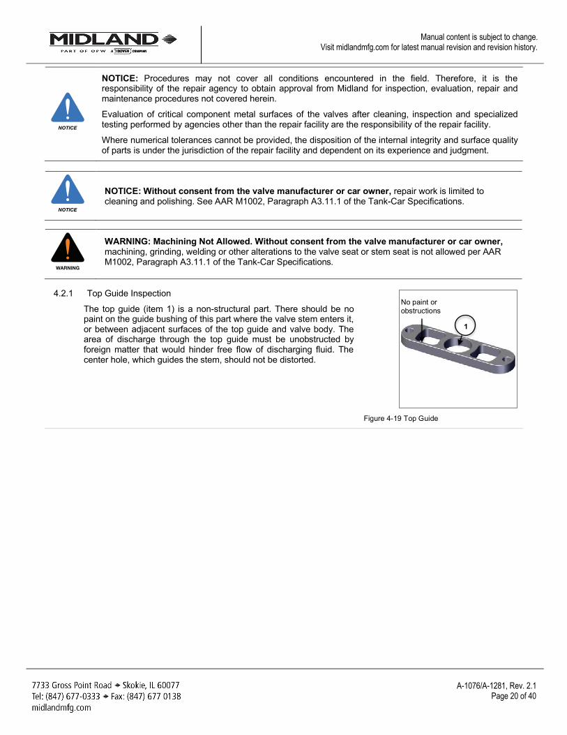
4.2.1 Top Guide Inspection
The top guide (item 1) is a non-structural part. There should be no paint on the guide bushing of this part where the valve stem enters it, or between adjacent surfaces of the top guide and valve body. The area of discharge through the top guide must be unobstructed by foreign matter that would hinder free flow of discharging fluid. The center hole, which guides the stem, should not be distorted.
Figure 4-19 Top Guide
NOTICE
NOTICE
WARNING
No paint or obstructions
1
A-1076/A-1281, Rev. 2.1
Page 21 of 40
Manual content is subject to change. Visit midlandmfg.com for latest manual revision and revision history.
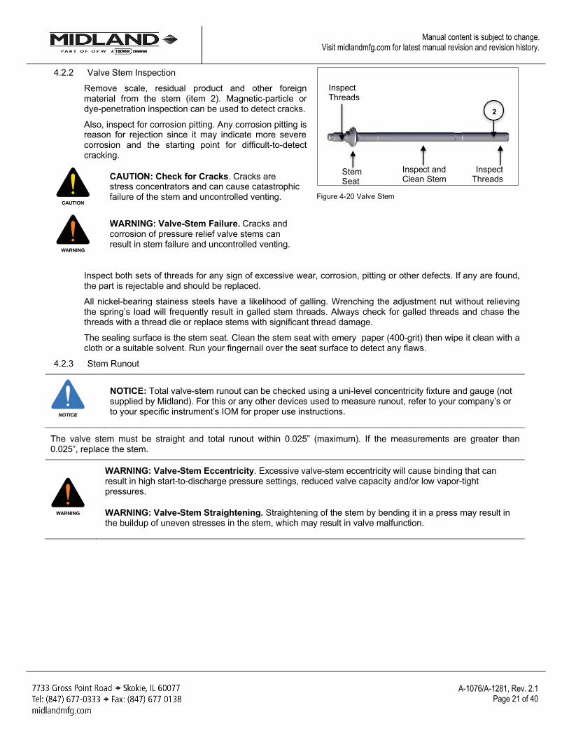
4.2.2 Valve Stem Inspection
Remove scale, residual product and other foreign material from the stem (item 2). Magnetic-particle or dye-penetration inspection can be used to detect cracks.
Also, inspect for corrosion pitting. Any corrosion pitting is reason for rejection since it may indicate more severe corrosion and the starting point for difficult-to-detect cracking.
CAUTION: Check for Cracks. Cracks are stress concentrators and can cause catastrophic failure of the stem and uncontrolled venting.
WARNING: Valve-Stem Failure. Cracks and corrosion of pressure relief valve stems can result in stem failure and uncontrolled venting.
Figure 4-20 Valve Stem
Inspect both sets of threads for any sign of excessive wear, corrosion, pitting or other defects. If any are found, the part is rejectable and should be replaced.
All nickel-bearing stainess steels have a likelihood of galling. Wrenching the adjustment nut without relieving the spring’s load will frequently result in galled stem threads. Always check for galled threads and chase the threads with a thread die or replace stems with significant thread damage.
The sealing surface is the stem seat. Clean the stem seat with emery paper (400-grit) then wipe it clean with a cloth or a suitable solvent. Run your fingernail over the seat surface to detect any flaws.
4.2.3 Stem Runout
NOTICE: Total valve-stem runout can be checked using a uni-level concentricity fixture and gauge (not supplied by Midland). For this or any other devices used to measure runout, refer to your company’s or to your specific instrument’s IOM for proper use instructions.
The valve stem must be straight and total runout within 0.025” (maximum). If the measurements are greater than 0.025”, replace the stem.
WARNING: Valve-Stem Eccentricity. Excessive valve-stem eccentricity will cause binding that can result in high start-to-discharge pressure settings, reduced valve capacity and/or low vapor-tight pressures.
WARNING: Valve-Stem Straightening. Straightening of the stem by bending it in a press may result in the buildup of uneven stresses in the stem, which may result in valve malfunction.
CAUTION
WARNING
NOTICE
WARNING
Inspect and Clean Stem
Inspect Threads
Inspect Threads
Stem Seat
2
A-1076/A-1281, Rev. 2.1
Page 22 of 40
Manual content is subject to change. Visit midlandmfg.com for latest manual revision and revision history.
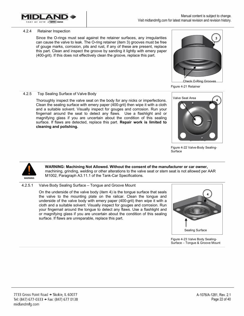
4.2.4 Retainer Inspection
Since the O-rings must seal against the retainer surfaces, any irregularities can cause the valve to leak. The O-ring retainer (item 3) grooves must be free of gouge marks, corrosion, pits and rust, if any of these are present, replace this part. Clean and inspect the groove by sanding it lightly with emery paper (400-grit). If this does not effectively clean the groove, replace this part.
Figure 4-21 Retainer
4.2.5 Top Sealing Surface of Valve Body Thoroughly inspect the valve seat on the body for any nicks or imperfections. Clean the sealing surface with emery paper (400-grit) then wipe it with a cloth and a suitable solvent. Visually inspect for gouges and corrosion. Run your fingernail around the seat to detect any flaws. Use a flashlight and or magnifying glass if you are uncertain about the condition of this sealing surface. If flaws are detected, replace this part. Repair work is limited to cleaning and polishing.
Figure 4-22 Valve-Body Sealing-Surface
WARNING: Machining Not Allowed. Without the consent of the manufacturer or car owner, machining, grinding, welding or other alterations to the valve seat or stem seat is not allowed per AAR M1002, Paragraph A3.11.1 of the Tank-Car Specifications.
4.2.5.1 Valve Body Sealing Surface – Tongue and Groove Mount
On the underside of the valve body (item 4) is the tongue surface that seals the valve to the mounting plate on the railcar. Clean the tongue and underside of the valve body with emery paper (400-grit) then wipe it with a cloth and a suitable solvent. Visually inspect for gouges and corrosion. Run your fingernail around the tongue to detect any flaws. Use a flashlight and or magnifying glass if you are uncertain about the condition of this sealing surface. If flaws are unreparable, replace this part.
Figure 4-23 Valve Body Sealing-Surface – Tongue & Groove Mount
WARNING
Check O-Ring Grooves
3
4 Valve Seat Area
4
Sealing Surface
A-1076/A-1281, Rev. 2.1
Page 23 of 40
Manual content is subject to change. Visit midlandmfg.com for latest manual revision and revision history.
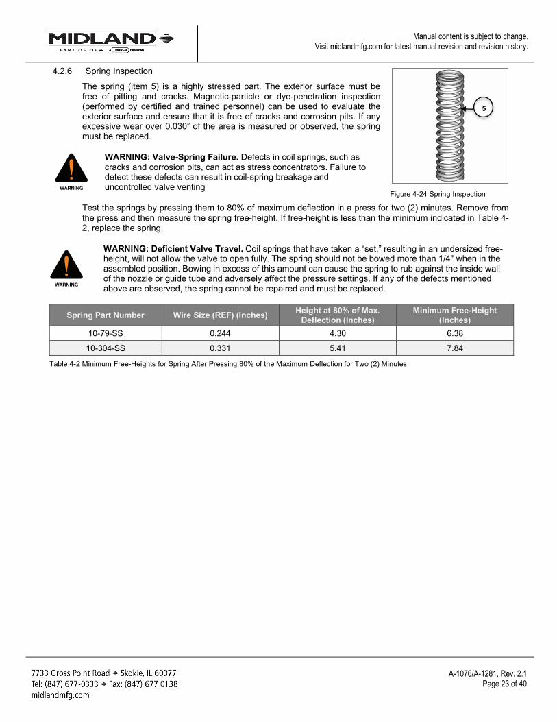
4.2.6 Spring Inspection
The spring (item 5) is a highly stressed part. The exterior surface must be free of pitting and cracks. Magnetic-particle or dye-penetration inspection (performed by certified and trained personnel) can be used to evaluate the exterior surface and ensure that it is free of cracks and corrosion pits. If any excessive wear over 0.030” of the area is measured or observed, the spring must be replaced.
WARNING: Valve-Spring Failure. Defects in coil springs, such as cracks and corrosion pits, can act as stress concentrators. Failure to detect these defects can result in coil-spring breakage and uncontrolled valve venting
Figure 4-24 Spring Inspection
Test the springs by pressing them to 80% of maximum deflection in a press for two (2) minutes. Remove from the press and then measure the spring free-height. If free-height is less than the minimum indicated in Table 4-2, replace the spring.
WARNING: Deficient Valve Travel. Coil springs that have taken a “set,” resulting in an undersized free-height, will not allow the valve to open fully. The spring should not be bowed more than 1/4" when in the assembled position. Bowing in excess of this amount can cause the spring to rub against the inside wall of the nozzle or guide tube and adversely affect the pressure settings. If any of the defects mentioned above are observed, the spring cannot be repaired and must be replaced.
Spring Part Number Wire Size (REF) (Inches) Height at 80% of Max. Deflection (Inches)
Minimum Free-Height (Inches)
10-79-SS 0.244 4.30 6.38
10-304-SS 0.331 5.41 7.84
Table 4-2 Minimum Free-Heights for Spring After Pressing 80% of the Maximum Deflection for Two (2) Minutes
WARNING
WARNING
5
A-1076/A-1281, Rev. 2.1
Page 24 of 40
Manual content is subject to change. Visit midlandmfg.com for latest manual revision and revision history.
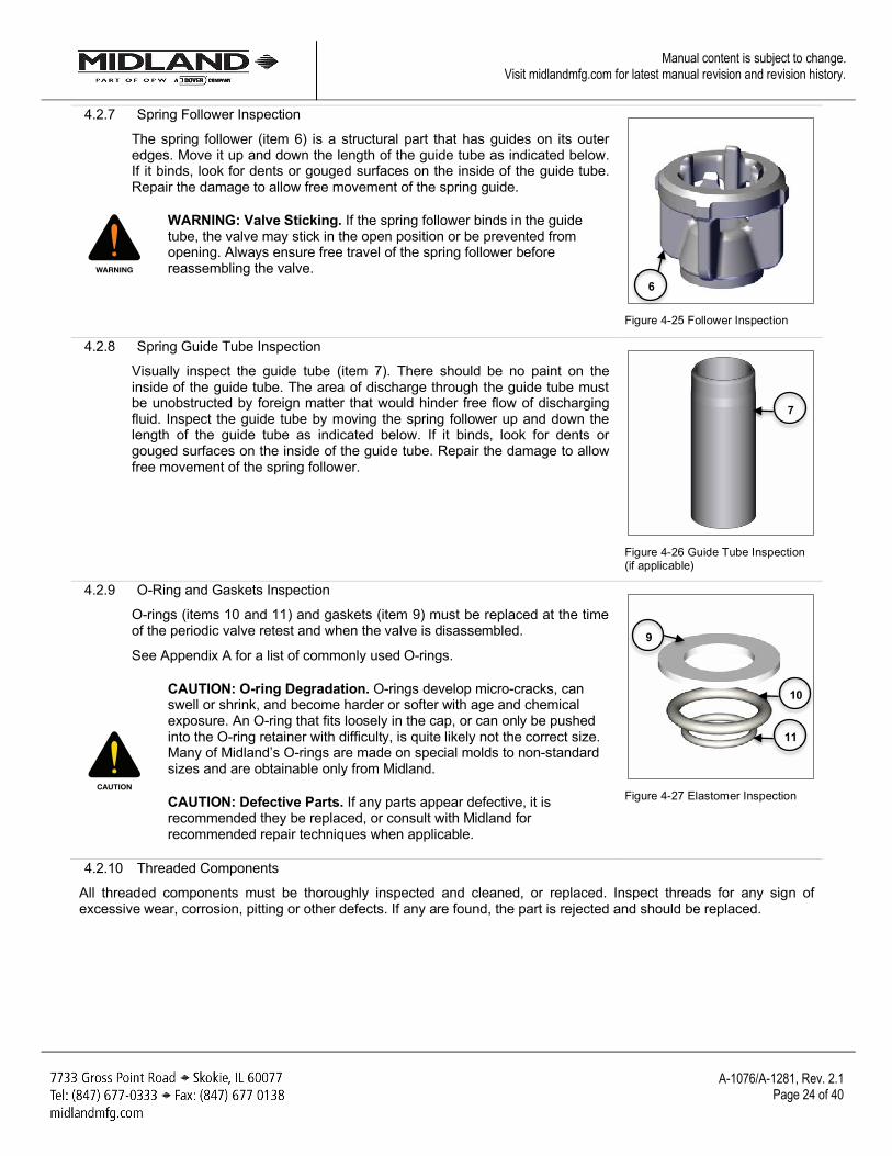
4.2.7 Spring Follower Inspection
The spring follower (item 6) is a structural part that has guides on its outer edges. Move it up and down the length of the guide tube as indicated below. If it binds, look for dents or gouged surfaces on the inside of the guide tube. Repair the damage to allow free movement of the spring guide.
WARNING: Valve Sticking. If the spring follower binds in the guide tube, the valve may stick in the open position or be prevented from opening. Always ensure free travel of the spring follower before reassembling the valve.
Figure 4-25 Follower Inspection
4.2.8 Spring Guide Tube Inspection
Visually inspect the guide tube (item 7). There should be no paint on the inside of the guide tube. The area of discharge through the guide tube must be unobstructed by foreign matter that would hinder free flow of discharging fluid. Inspect the guide tube by moving the spring follower up and down the length of the guide tube as indicated below. If it binds, look for dents or gouged surfaces on the inside of the guide tube. Repair the damage to allow free movement of the spring follower.
Figure 4-26 Guide Tube Inspection (if applicable)
4.2.9 O-Ring and Gaskets Inspection
O-rings (items 10 and 11) and gaskets (item 9) must be replaced at the time of the periodic valve retest and when the valve is disassembled.
See Appendix A for a list of commonly used O-rings.
CAUTION: O-ring Degradation. O-rings develop micro-cracks, can swell or shrink, and become harder or softer with age and chemical exposure. An O-ring that fits loosely in the cap, or can only be pushed into the O-ring retainer with difficulty, is quite likely not the correct size. Many of Midland’s O-rings are made on special molds to non-standard sizes and are obtainable only from Midland.
CAUTION: Defective Parts. If any parts appear defective, it is recommended they be replaced, or consult with Midland for recommended repair techniques when applicable.
Figure 4-27 Elastomer Inspection
4.2.10 Threaded Components
All threaded components must be thoroughly inspected and cleaned, or replaced. Inspect threads for any sign of excessive wear, corrosion, pitting or other defects. If any are found, the part is rejected and should be replaced.
WARNING
CAUTION
6
7
9
10
11
A-1076/A-1281, Rev. 2.1
Page 25 of 40
Manual content is subject to change. Visit midlandmfg.com for latest manual revision and revision history.
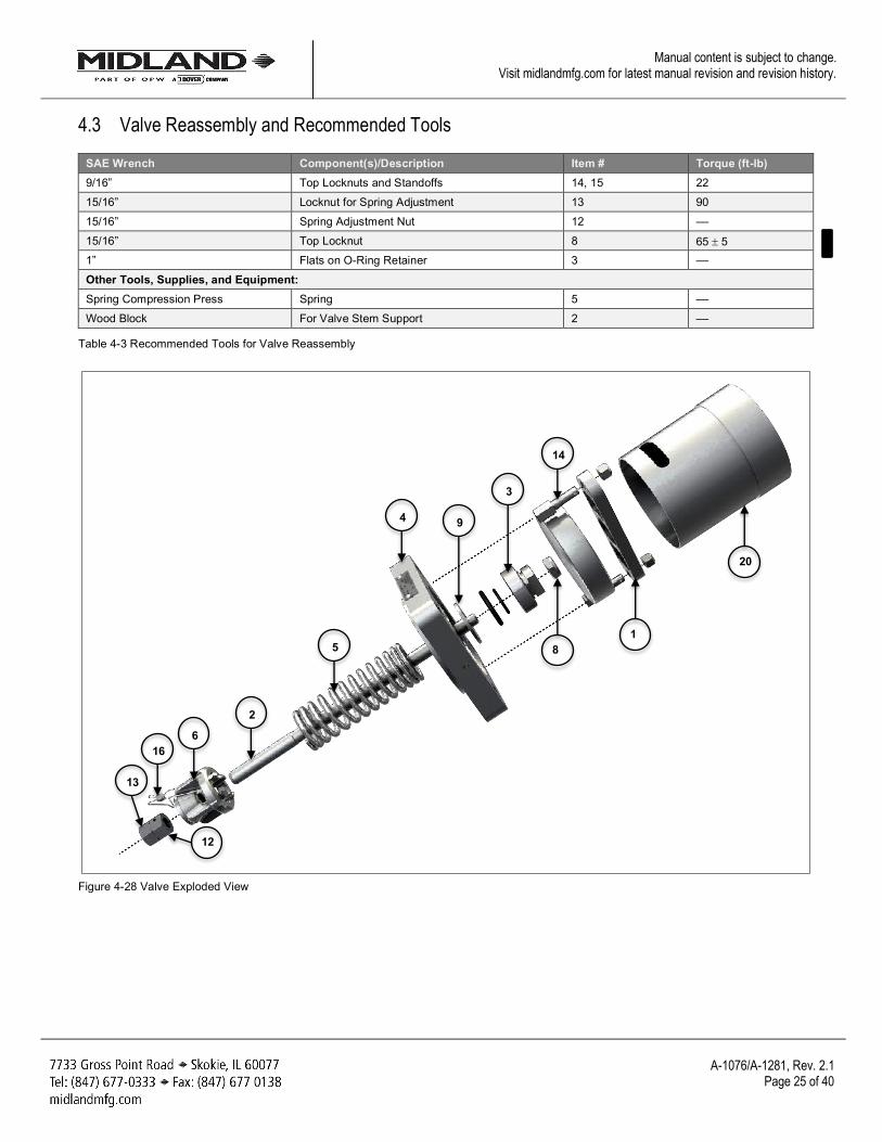
4.3 Valve Reassembly and Recommended Tools
SAE Wrench Component(s)/Description Item # Torque (ft-lb) 9/16” Top Locknuts and Standoffs 14, 15 22 15/16” Locknut for Spring Adjustment 13 90 15/16” Spring Adjustment Nut 12 –– 15/16” Top Locknut 8 65 ± 5 1” Flats on O-Ring Retainer 3 –– Other Tools, Supplies, and Equipment: Spring Compression Press Spring 5 –– Wood Block For Valve Stem Support 2 ––
Table 4-3 Recommended Tools for Valve Reassembly
Figure 4-28 Valve Exploded View
2
5
4
6
3
20
1
14
8
9
12
13
16
A-1076/A-1281, Rev. 2.1
Page 26 of 40
Manual content is subject to change. Visit midlandmfg.com for latest manual revision and revision history.
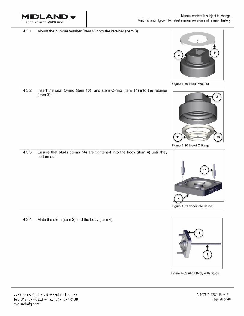
4.3.1 Mount the bumper washer (item 9) onto the retainer (item 3).
Figure 4-29 Install Washer
4.3.2 Insert the seat O-ring (item 10) and stem O-ring (item 11) into the retainer (item 3).
Figure 4-30 Insert O-Rings
4.3.3 Ensure that studs (items 14) are tightened into the body (item 4) until they bottom out.
Figure 4-31 Assemble Studs
4.3.4 Mate the stem (item 2) and the body (item 4).
Figure 4-32 Align Body with Studs
3 9
11 10
4
14
3
2
4
A-1076/A-1281, Rev. 2.1
Page 27 of 40
Manual content is subject to change. Visit midlandmfg.com for latest manual revision and revision history.
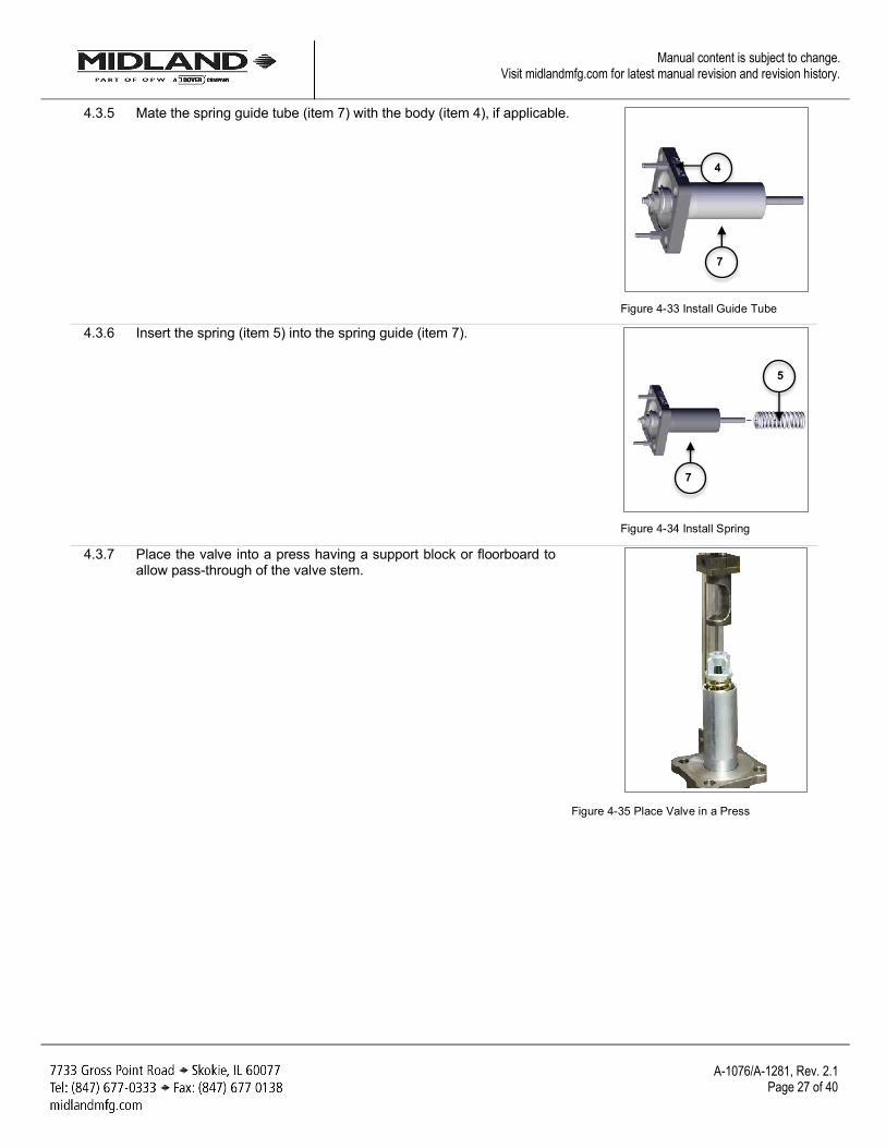
4.3.5 Mate the spring guide tube (item 7) with the body (item 4), if applicable.
Figure 4-33 Install Guide Tube
4.3.6 Insert the spring (item 5) into the spring guide (item 7).
Figure 4-34 Install Spring
4.3.7 Place the valve into a press having a support block or floorboard to allow pass-through of the valve stem.
Figure 4-35 Place Valve in a Press
4
7
5
7
A-1076/A-1281, Rev. 2.1
Page 28 of 40
Manual content is subject to change. Visit midlandmfg.com for latest manual revision and revision history.
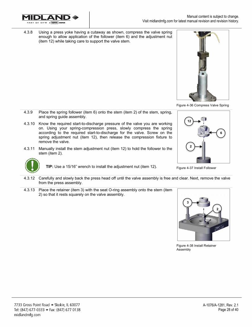
4.3.8 Using a press yoke having a cutaway as shown, compress the valve spring enough to allow application of the follower (item 6) and the adjustment nut (item 12) while taking care to support the valve stem.
Figure 4-36 Compress Valve Spring
4.3.9 Place the spring follower (item 6) onto the stem (item 2) of the stem, spring, and spring guide assembly.
4.3.10 Know the required start-to-discharge pressure of the valve you are working on. Using your spring-compression press, slowly compress the spring according to the required start-to-discharge for the valve. Screw on the spring adjustment nut (item 12), then release the compression fixture to remove the valve.
4.3.11 Manually install the stem adjustment nut (item 12) to hold the follower to the stem (item 2).
TIP: Use a 15/16” wrench to install the adjustment nut (item 12).
Figure 4-37 Install Follower
4.3.12 Carefully and slowly back the press head off until the valve assembly is free and clear. Next, remove the valve from the press assembly.
4.3.13 Place the retainer (item 3) with the seat O-ring assembly onto the stem (item 2) so that it rests squarely on the valve assembly.
Figure 4-38 Install Retainer Assembly
2
12
6
2
3
A-1076/A-1281, Rev. 2.1
Page 29 of 40
Manual content is subject to change. Visit midlandmfg.com for latest manual revision and revision history.
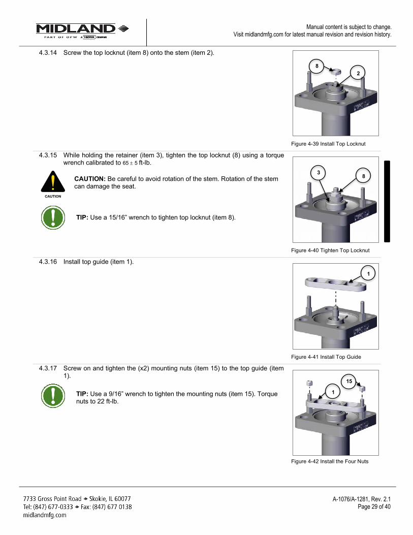
4.3.14 Screw the top locknut (item 8) onto the stem (item 2).
Figure 4-39 Install Top Locknut
4.3.15 While holding the retainer (item 3), tighten the top locknut (8) using a torque wrench calibrated to 65 ± 5 ft-lb.
CAUTION: Be careful to avoid rotation of the stem. Rotation of the stem can damage the seat.
TIP: Use a 15/16” wrench to tighten top locknut (item 8).
Figure 4-40 Tighten Top Locknut
4.3.16 Install top guide (item 1).
Figure 4-41 Install Top Guide
4.3.17 Screw on and tighten the (x2) mounting nuts (item 15) to the top guide (item 1).
TIP: Use a 9/16” wrench to tighten the mounting nuts (item 15). Torque nuts to 22 ft-lb.
Figure 4-42 Install the Four Nuts
CAUTION
8
3 8
2
1
1
15
A-1076/A-1281, Rev. 2.1
Page 30 of 40
Manual content is subject to change. Visit midlandmfg.com for latest manual revision and revision history.
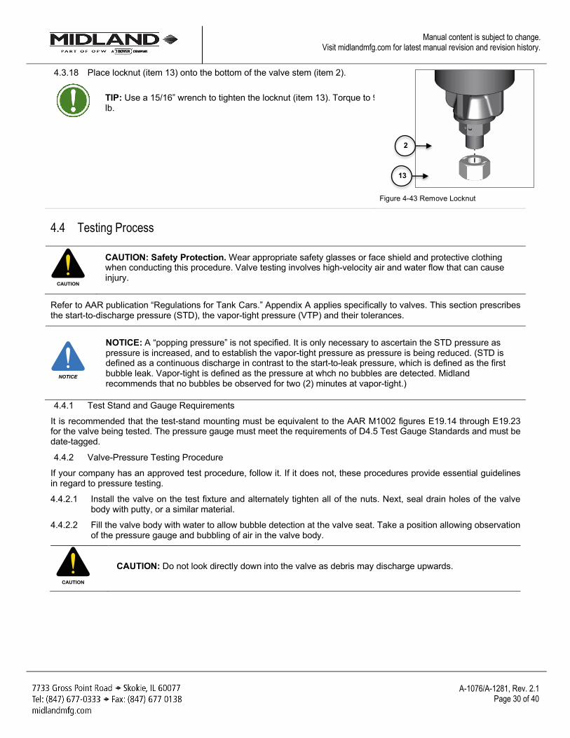
4.3.18 Place locknut (item 13) onto the bottom of the valve stem (item 2).
TIP: Use a 15/16” wrench to tighten the locknut (item 13). Torque to 90 ft-lb.
Figure 4-43 Remove Locknut
4.4 Testing Process
CAUTION: Safety Protection. Wear appropriate safety glasses or face shield and protective clothing when conducting this procedure. Valve testing involves high-velocity air and water flow that can cause injury.
Refer to AAR publication “Regulations for Tank Cars.” Appendix A applies specifically to valves. This section prescribes the start-to-discharge pressure (STD), the vapor-tight pressure (VTP) and their tolerances.
NOTICE: A “popping pressure” is not specified. It is only necessary to ascertain the STD pressure as pressure is increased, and to establish the vapor-tight pressure as pressure is being reduced. (STD is defined as a continuous discharge in contrast to the start-to-leak pressure, which is defined as the first bubble leak. Vapor-tight is defined as the pressure at whch no bubbles are detected. Midland recommends that no bubbles be observed for two (2) minutes at vapor-tight.)
4.4.1 Test Stand and Gauge Requirements
It is recommended that the test-stand mounting must be equivalent to the AAR M1002 figures E19.14 through E19.23 for the valve being tested. The pressure gauge must meet the requirements of D4.5 Test Gauge Standards and must be date-tagged.
4.4.2 Valve-Pressure Testing Procedure
If your company has an approved test procedure, follow it. If it does not, these procedures provide essential guidelines in regard to pressure testing.
4.4.2.1 Install the valve on the test fixture and alternately tighten all of the nuts. Next, seal drain holes of the valve body with putty, or a similar material.
4.4.2.2 Fill the valve body with water to allow bubble detection at the valve seat. Take a position allowing observation of the pressure gauge and bubbling of air in the valve body.
CAUTION: Do not look directly down into the valve as debris may discharge upwards.
CAUTION
NOTICE
CAUTION
2
13
A-1076/A-1281, Rev. 2.1
Page 31 of 40
Manual content is subject to change. Visit midlandmfg.com for latest manual revision and revision history.
4.4.3 Testing
4.4.3.1 Increase the test air pressure slowly.
4.4.3.2 Increase the air pressure until the valve start-to-discharge (STD) pressure is reached. The initial opening of the valve may be slightly high and not indicative of the actual STD because the O-ring may have been partially stuck to the valve seat. See table below for valve start-to-discharge (STD) and vapor-tight pressure (VTP) settings.
STD Settings ± 3% VTP Settings
75 psig ± 3 psig 60 psig minimum
280.5 224
Table 4-4 Start-To-Discharge (STD) and Vapor-Tight Pressure (VTP) Settings
4.4.3.3 Observe the STD pressure and then bleed off the pressure slowly to observe the VTP.
4.4.3.4 Repeat this procedure to ensure performance. The STD and VTP should be consistent.
NOTICE: AAR Specifications state that the VTP is 80% of the STD. Valves with good seats and O-rings should exhibit a VTP above 80% of the STD (usually up to 95% of the STD).
4.4.3.5 Record the values.
NOTICE: If the test results are erratic, troubleshooting is more complex. Consult your supervising engineer or a Midland Manufacturing representative.
4.4.3.6 When the test results are acceptable, tighten the bottom locknut (item 13) to torque at 85–95 ft-lb.
4.4.3.7 If the STD or VTP is not satisfactory, follow the Valve-Setting Adjustment procedure in Section 4.5.
NOTICE
NOTICE
A-1076/A-1281, Rev. 2.1
Page 32 of 40
Manual content is subject to change. Visit midlandmfg.com for latest manual revision and revision history.
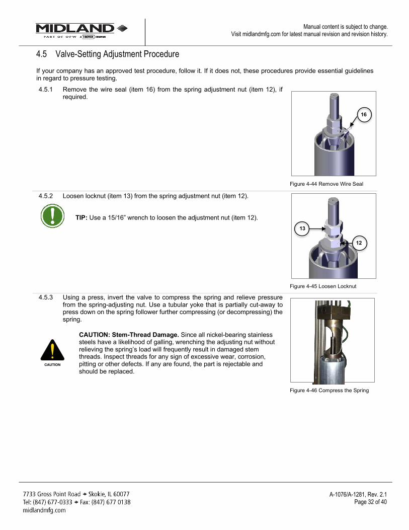
4.5 Valve-Setting Adjustment Procedure If your company has an approved test procedure, follow it. If it does not, these procedures provide essential guidelines in regard to pressure testing.
4.5.1 Remove the wire seal (item 16) from the spring adjustment nut (item 12), if required.
Figure 4-44 Remove Wire Seal
4.5.2 Loosen locknut (item 13) from the spring adjustment nut (item 12).
TIP: Use a 15/16” wrench to loosen the adjustment nut (item 12).
Figure 4-45 Loosen Locknut
4.5.3 Using a press, invert the valve to compress the spring and relieve pressure from the spring-adjusting nut. Use a tubular yoke that is partially cut-away to press down on the spring follower further compressing (or decompressing) the spring.
CAUTION: Stem-Thread Damage. Since all nickel-bearing stainless steels have a likelihood of galling, wrenching the adjusting nut without relieving the spring’s load will frequently result in damaged stem threads. Inspect threads for any sign of excessive wear, corrosion, pitting or other defects. If any are found, the part is rejectable and should be replaced.
Figure 4-46 Compress the Spring
CAUTION
16
12
13
A-1076/A-1281, Rev. 2.1
Page 33 of 40
Manual content is subject to change. Visit midlandmfg.com for latest manual revision and revision history.
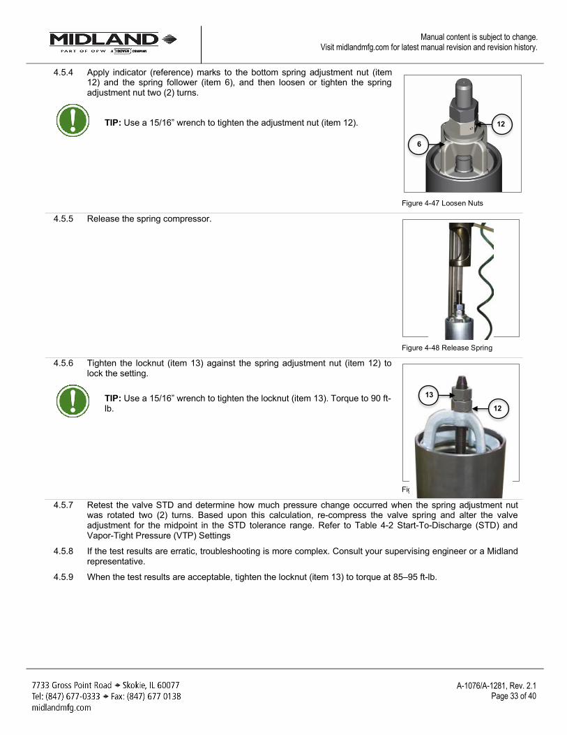
4.5.4 Apply indicator (reference) marks to the bottom spring adjustment nut (item 12) and the spring follower (item 6), and then loosen or tighten the spring adjustment nut two (2) turns.
TIP: Use a 15/16” wrench to tighten the adjustment nut (item 12).
Figure 4-47 Loosen Nuts
4.5.5 Release the spring compressor.
Figure 4-48 Release Spring
4.5.6 Tighten the locknut (item 13) against the spring adjustment nut (item 12) to lock the setting.
TIP: Use a 15/16” wrench to tighten the locknut (item 13). Torque to 90 ft-lb.
Figure 4-49 Tighten Locknut
4.5.7 Retest the valve STD and determine how much pressure change occurred when the spring adjustment nut was rotated two (2) turns. Based upon this calculation, re-compress the valve spring and alter the valve adjustment for the midpoint in the STD tolerance range. Refer to Table 4-2 Start-To-Discharge (STD) and Vapor-Tight Pressure (VTP) Settings
4.5.8 If the test results are erratic, troubleshooting is more complex. Consult your supervising engineer or a Midland representative.
4.5.9 When the test results are acceptable, tighten the locknut (item 13) to torque at 85–95 ft-lb.
12
6
13
12
A-1076/A-1281, Rev. 2.1
Page 34 of 40
Manual content is subject to change. Visit midlandmfg.com for latest manual revision and revision history.
4.6 Post-Test Procedure 4.6.1 After testing the valve, close the pressure inlet valve to the test chamber and vent the pressure in the test
stand. Remove putty and drain water. Then remove the valve from the test fixture.
4.6.2 Wipe or blow away any remaining soap suds and water used in the testing.
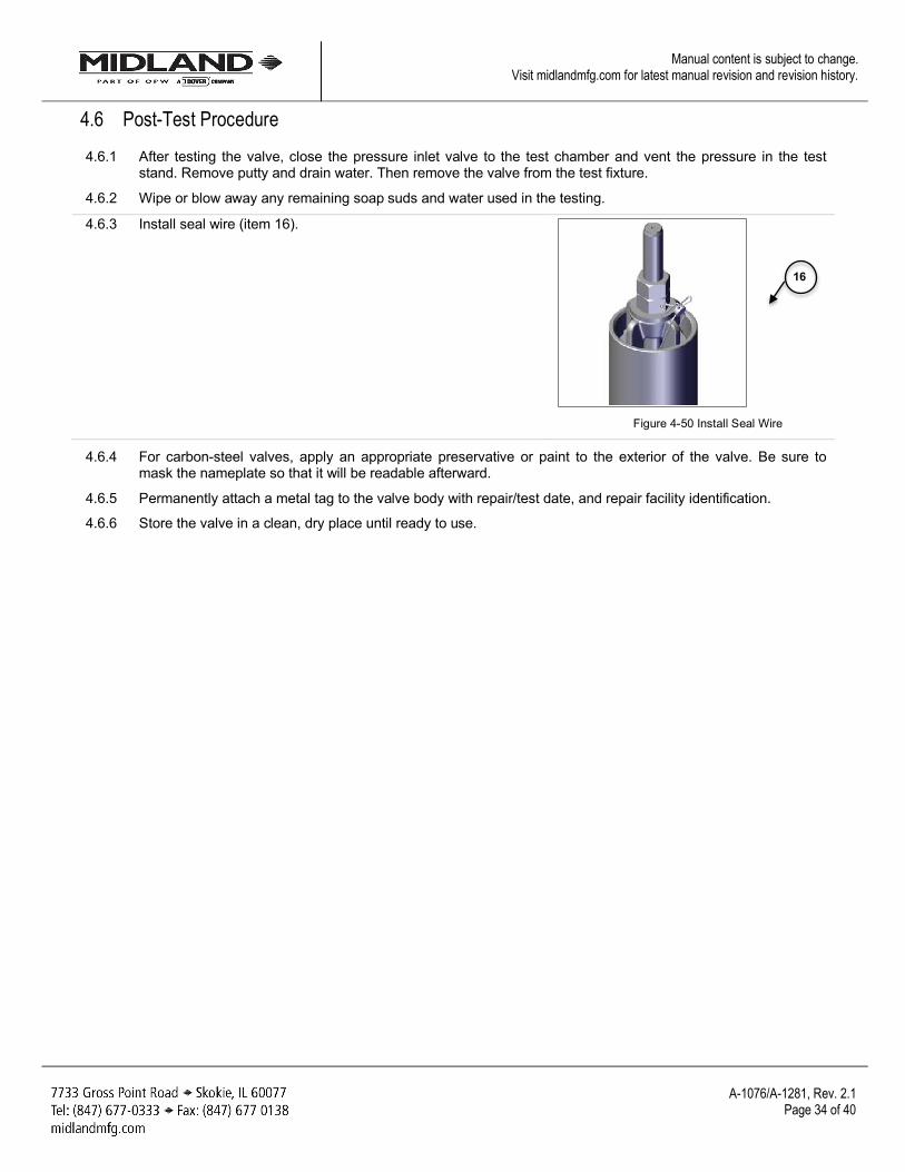
4.6.3 Install seal wire (item 16).
Figure 4-50 Install Seal Wire
4.6.4 For carbon-steel valves, apply an appropriate preservative or paint to the exterior of the valve. Be sure to mask the nameplate so that it will be readable afterward.
4.6.5 Permanently attach a metal tag to the valve body with repair/test date, and repair facility identification.
4.6.6 Store the valve in a clean, dry place until ready to use.
16
A-1076/A-1281, Rev. 2.1
Page 35 of 40
Manual content is subject to change. Visit midlandmfg.com for latest manual revision and revision history.
5 Routine Maintenance No regular, periodic maintenance of the mechanical working of this valve is required outside of regular standard qualification. However, Midland recommends that the installed valve be inspected on a regular basis to ensure that the tamper wire and weather cap are in place and that the external visible valve body is free of any foreign materials that could impact its intended operation.
NOTICE: Routine Maintenance involves valve inspection and component replacement for valves in-service on tank cars in accordance to the car owner’s standard maintenance program to ensure the valve performs the intended function without failure until the next qualification, or for the design life.
CAUTION: The repair procedure for leaking valves is intended only as a temporary repair to get the car to an unloading destination. Once the product is unloaded and pressure is relieved, the valve should be removed for a complete inspection and requalification.
5.1 Routine Repair Procedure
NOTICE: When performing this procedure, it is recommended that there is no pressure in the tank car.
SAE Wrench Component(s)/Description Item #
3/4” Nuts for Top Guide (x2) 15 1” Top Locknut 8 1” Flats on O-Ring Retainer 3 Other Tools, Supplies, and Equipment: Non-Scratching Tool to Remove O-Rings O-Ring 10, 11
Table 5-1 Recommended Tools for Valve Repair
5.1.1 Obtain the required tools and supplies before attempting maintenance or repair procedures. Table 1-3 outlines some suggested tools that may be needed.
NOTICE: Replaceable parts for In-Service Maintenance include: top guide (item 1), retainer (item 3), top locknut (item 8), neoprene washer (item 9), seat O-Ring (item 10), stem O-Ring (item 11), studs (items 14 and 14A), stud nuts (item 15), and wire seal (item 16). Refer to pages 6-10 for complete parts listings.
NOTICE
CAUTION
NOTICE
NOTICE
A-1076/A-1281, Rev. 2.1
Page 36 of 40
Manual content is subject to change. Visit midlandmfg.com for latest manual revision and revision history.
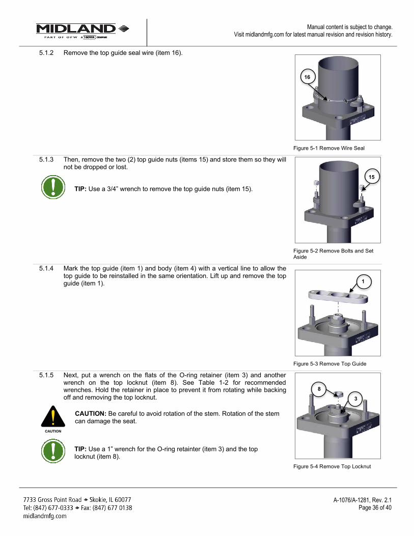
5.1.2 Remove the top guide seal wire (item 16).
Figure 5-1 Remove Wire Seal
5.1.3 Then, remove the two (2) top guide nuts (items 15) and store them so they will not be dropped or lost.
TIP: Use a 3/4” wrench to remove the top guide nuts (item 15).
Figure 5-2 Remove Bolts and Set Aside
5.1.4 Mark the top guide (item 1) and body (item 4) with a vertical line to allow the top guide to be reinstalled in the same orientation. Lift up and remove the top guide (item 1).
Figure 5-3 Remove Top Guide
5.1.5 Next, put a wrench on the flats of the O-ring retainer (item 3) and another wrench on the top locknut (item 8). See Table 1-2 for recommended wrenches. Hold the retainer in place to prevent it from rotating while backing off and removing the top locknut.
CAUTION: Be careful to avoid rotation of the stem. Rotation of the stem can damage the seat.
TIP: Use a 1” wrench for the O-ring retainter (item 3) and the top locknut (item 8).
Figure 5-4 Remove Top Locknut
CAUTION
16
15
1
8
3
A-1076/A-1281, Rev. 2.1
Page 37 of 40
Manual content is subject to change. Visit midlandmfg.com for latest manual revision and revision history.
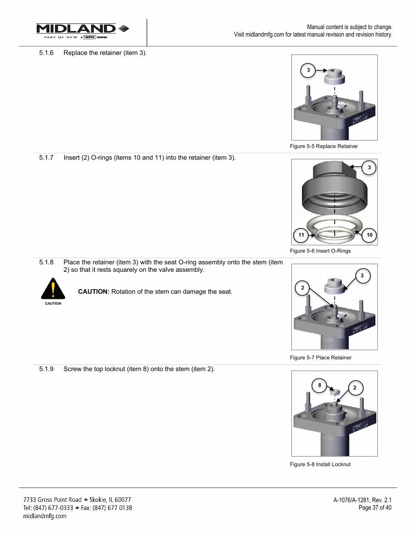
5.1.6 Replace the retainer (item 3).
Figure 5-5 Replace Retainer
5.1.7 Insert (2) O-rings (items 10 and 11) into the retainer (item 3).
Figure 5-6 Insert O-Rings
5.1.8 Place the retainer (item 3) with the seat O-ring assembly onto the stem (item 2) so that it rests squarely on the valve assembly.
CAUTION: Rotation of the stem can damage the seat.
Figure 5-7 Place Retainer
5.1.9 Screw the top locknut (item 8) onto the stem (item 2).
Figure 5-8 Install Locknut
CAUTION
3
11 10
3
2
3
8 2
A-1076/A-1281, Rev. 2.1
Page 38 of 40
Manual content is subject to change. Visit midlandmfg.com for latest manual revision and revision history.
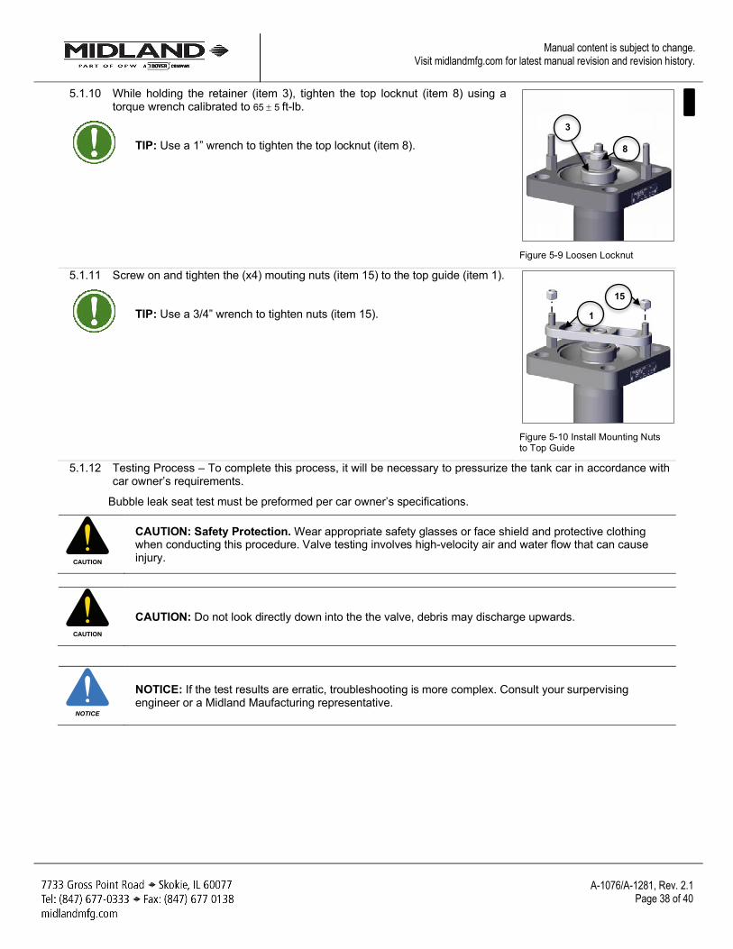
5.1.10 While holding the retainer (item 3), tighten the top locknut (item 8) using a torque wrench calibrated to 65 ± 5 ft-lb.
TIP: Use a 1” wrench to tighten the top locknut (item 8).
Figure 5-9 Loosen Locknut
5.1.11 Screw on and tighten the (x4) mouting nuts (item 15) to the top guide (item 1).
TIP: Use a 3/4” wrench to tighten nuts (item 15).
Figure 5-10 Install Mounting Nuts to Top Guide
5.1.12 Testing Process – To complete this process, it will be necessary to pressurize the tank car in accordance with car owner’s requirements.
Bubble leak seat test must be preformed per car owner’s specifications.
CAUTION: Safety Protection. Wear appropriate safety glasses or face shield and protective clothing when conducting this procedure. Valve testing involves high-velocity air and water flow that can cause injury.
CAUTION: Do not look directly down into the the valve, debris may discharge upwards.
NOTICE: If the test results are erratic, troubleshooting is more complex. Consult your surpervising engineer or a Midland Maufacturing representative.
CAUTION
CAUTION
NOTICE
8
3
1
15

A-1076/A-1281, Rev. 2.1
Page 39 of 40
Manual content is subject to change. Visit midlandmfg.com for latest manual revision and revision history.
6 Emergency Response for Leaking Valve
NOTICE: Emergency Response is the temporary remediation to a valve observed to be emitting product in an unintended manner. It is possible to replace o-rings on an internal style valve installed on a pressurized tank car. Since leak repair is a temporary measure, once the car is unloaded and pressure is relieved, the valve should be removed for complete inspection, repairs, and full qualification in accordance to the car owner’s standard qualification and maintenance program. Leak repair is unscheduled maintenance and is not part of scheduled maintenance.
6.1 Follow All Routine Maintenance Procedures
NOTICE: This manual is not intended to provide all the information necessary to conduct emergency repair procedures. Personnel must be specially trained and qualified in hazmat procedures before attempting to service a leaking valve on a rail tank car.
NOTICE
NOTICE

© Copyright 2017, OPW. Printed in USA. © 2017 Delaware Capital Formation, Inc. All Rights Reserved.