Embed Size (px)
Citation preview
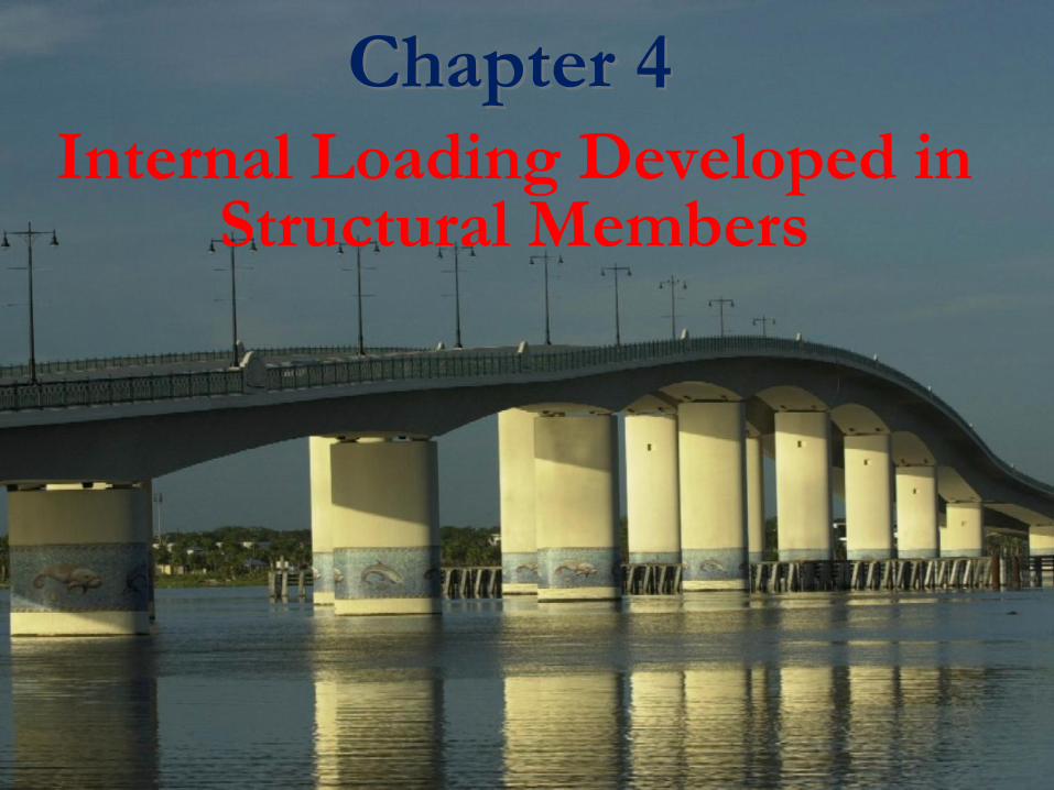
Chapter 4
Internal Loading Developed in Structural Members
Chapter 4
Internal Loading Developed in Structural
Members
Internal loading at a specified Point
In General
• The loading for coplanar structure will
consist of a normal force N, shear force V,
and bending moment M.
• These loading actually represent the resultants
of the stress distribution acting over the member’s
cross-sectional are

Sign Convention+ve Sign
Procedure for analysis
• Support Reaction
• Free-Body Diagram
• Equation of Equilibrium
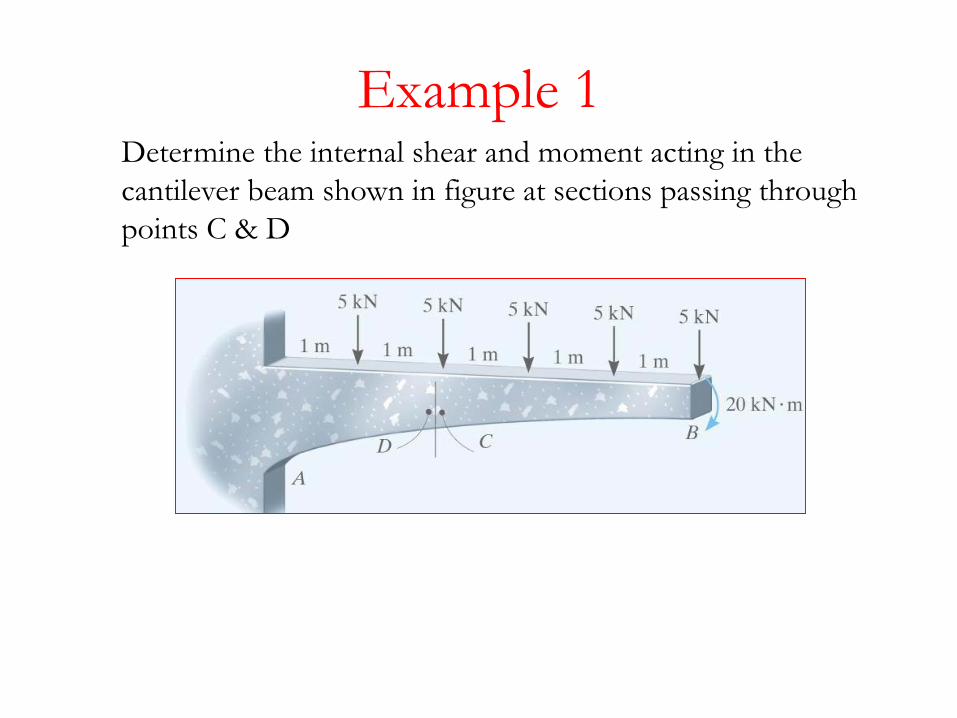
Example 1Determine the internal shear and moment acting in the
cantilever beam shown in figure at sections passing through
points C & D
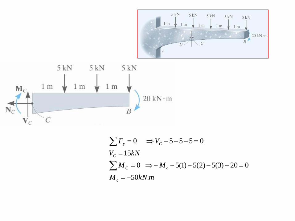
mkNM
MM
kNV
V F
c
cC
C
Cy
.50
020)3(5)2(5)1(5 0
15
05550
mkNM
MM
kNV
V F
D
DC
C
Dy
.50
020)3(5)2(5)1(5 0
20
055550
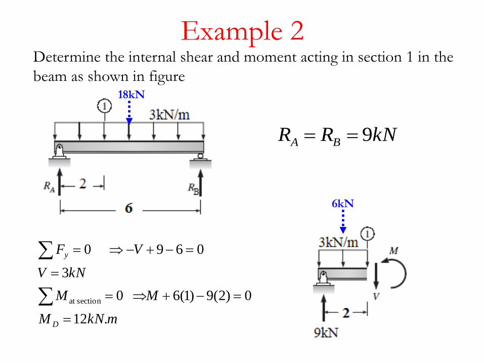
Example 2
kNRR BA 9
mkNM
MM
kNV
V F
D
y
.12
0)2(9)1(6 0
3
0690
sectionat
6kN
Determine the internal shear and moment acting in section 1 in the
beam as shown in figure18kN

Example 3Determine the internal shear and moment acting in the
cantilever beam shown in figure at sections passing through
points C
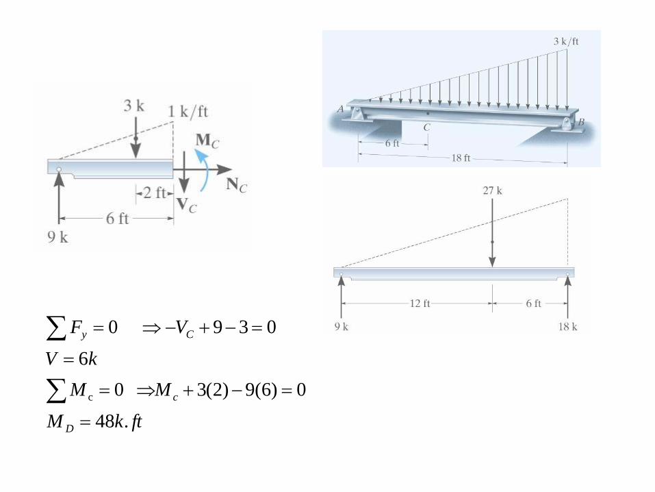
ftkM
MM
kV
V F
D
c
Cy
.48
0)6(9)2(3 0
6
0390
c
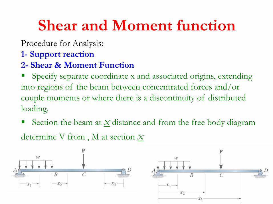
Shear and Moment functionProcedure for Analysis:
1- Support reaction
2- Shear & Moment Function
Specify separate coordinate x and associated origins, extending
into regions of the beam between concentrated forces and/or
couple moments or where there is a discontinuity of distributed
loading.
Section the beam at x distance and from the free body diagram
determine V from , M at section x
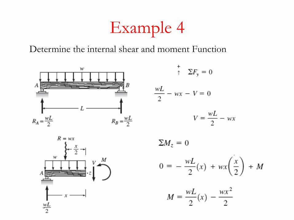
Example 4Determine the internal shear and moment Function
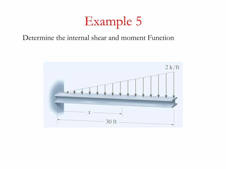
Example 5Determine the internal shear and moment Function
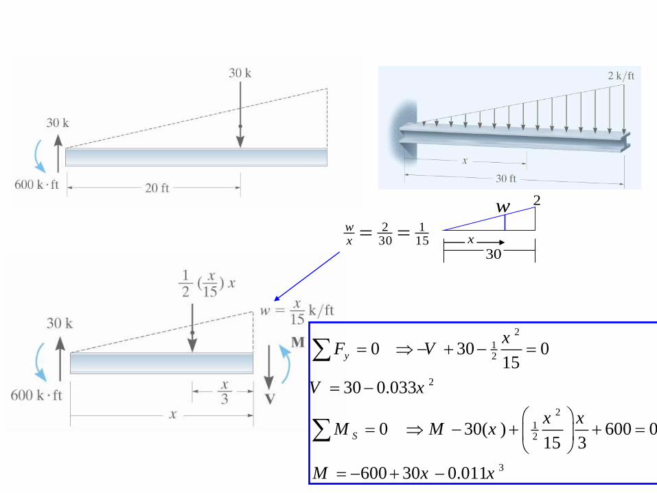
151
302
xw
2
12
2
2
12
3
0 30 015
30 0.033
0 30( ) 600 015 3
600 30 0.011
y
S
xF V
V x
x xM M x
M x x
w 2
30x
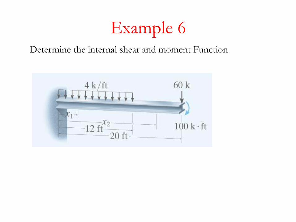
Example 6Determine the internal shear and moment Function

2
11
211S
1
1
1
21081588
041081588 0
4108
041080
120
1
xxM
xxMM
xV
xV F
x
x
y
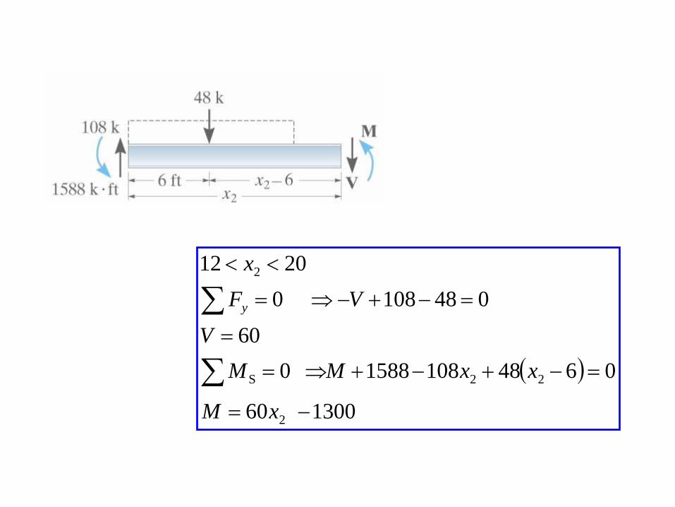
130060
06481081588 0
60
0481080
2012
2
22S
2
xM
xxMM
V
V F
x
y
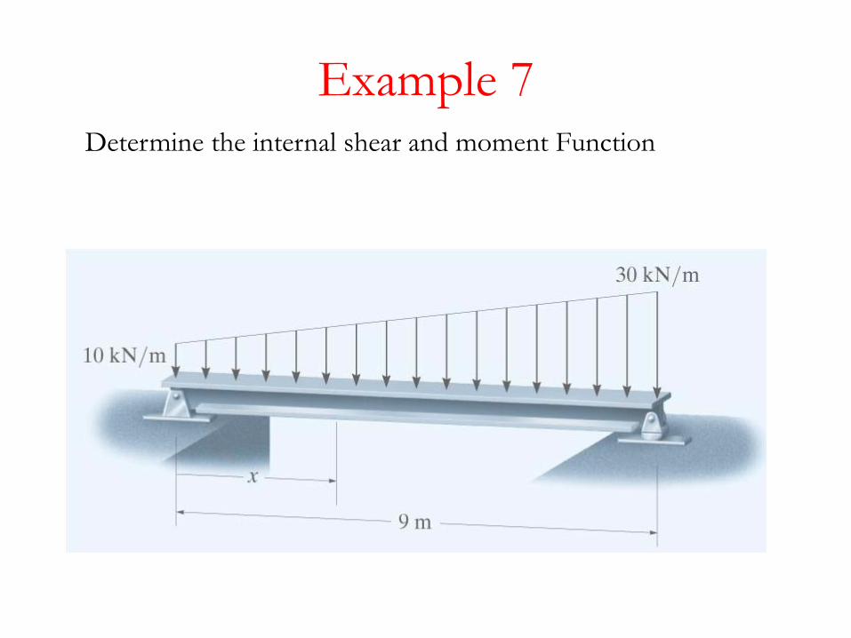
Example 7Determine the internal shear and moment Function
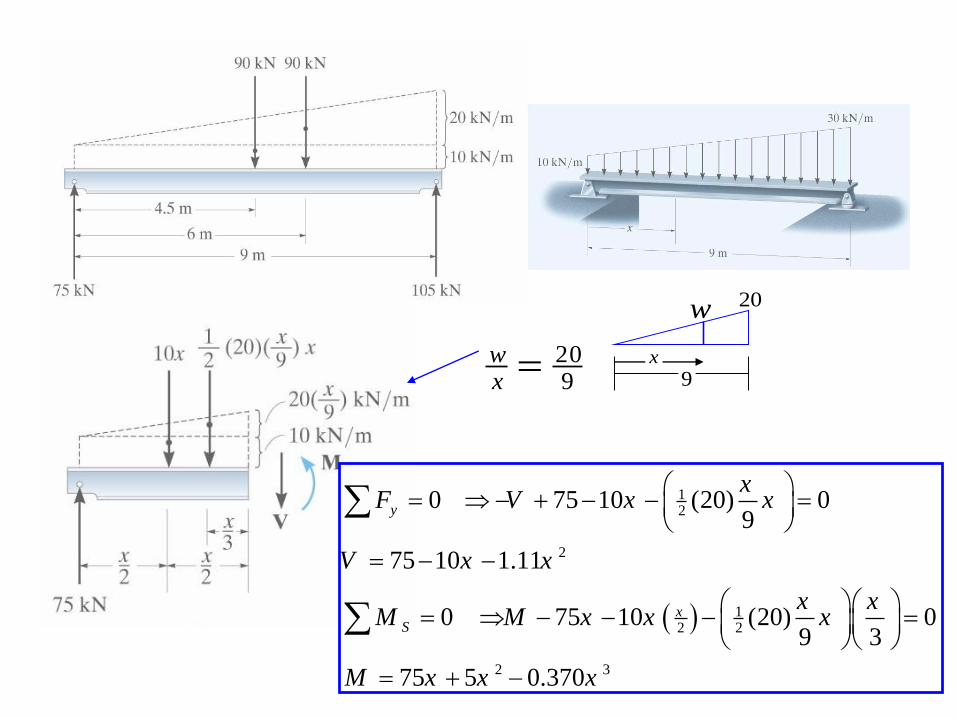
920
xw
12
2
12 2
2 3
0 75 10 (20) 09
75 10 1.11
0 75 10 (20) 09 3
75 5 0.370
y
xS
xF V x x
V x x
x xM M x x x
M x x x
w 20
9x
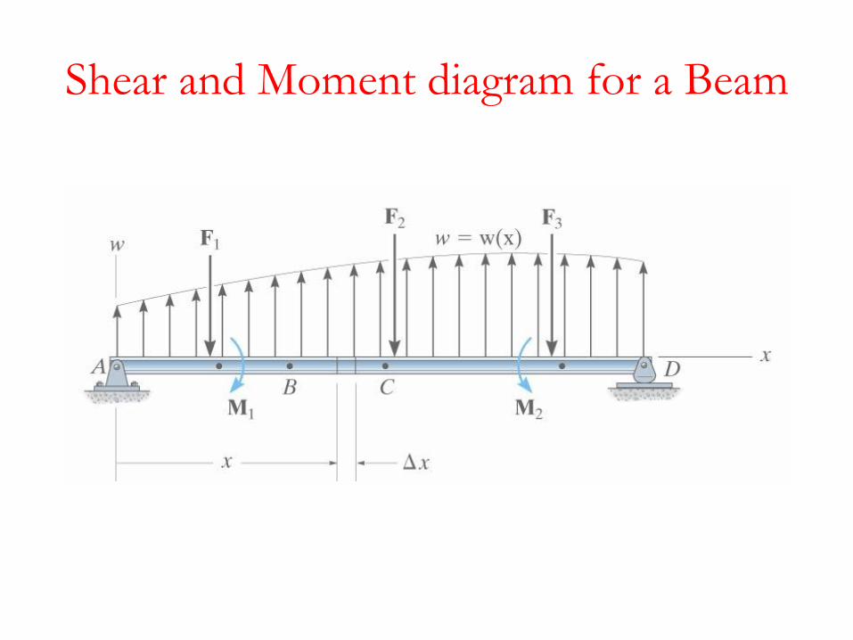
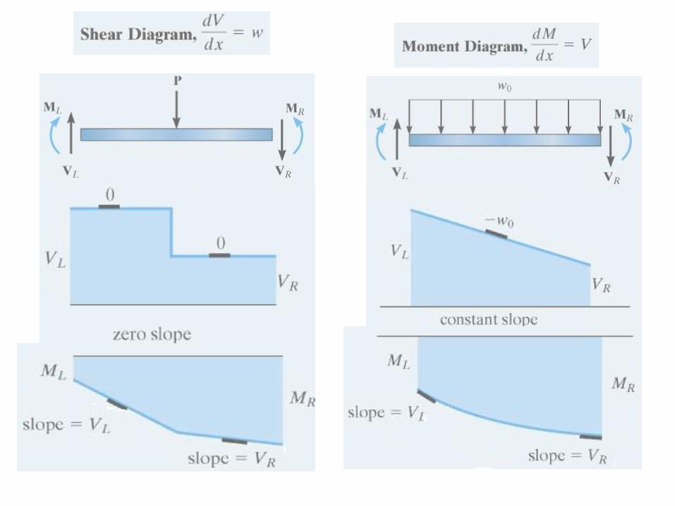
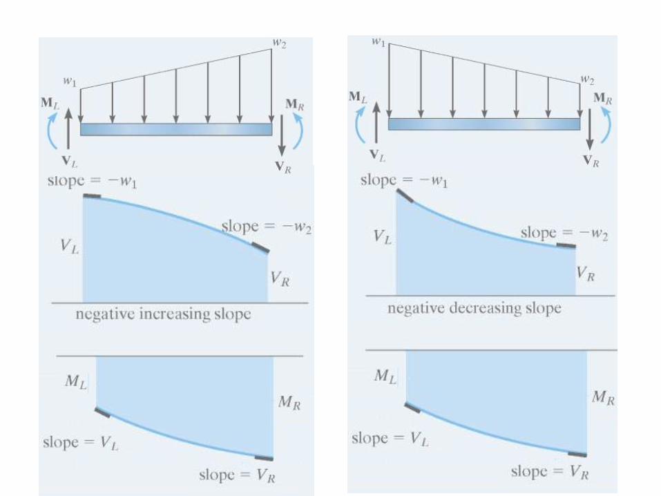
Shear and Moment diagram for a Beam
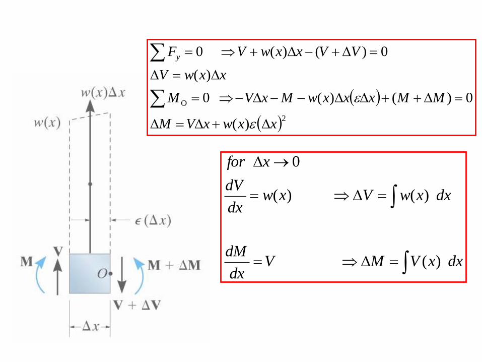
2O
)(
0)()( 0
)(
0)()(0
xxwxVM
MMxxxwMxVM
xxwV
VVxxwV Fy
dxxVMVdx
dM
dxxwVxwdx
dV
xfor
)(
)( )(
0
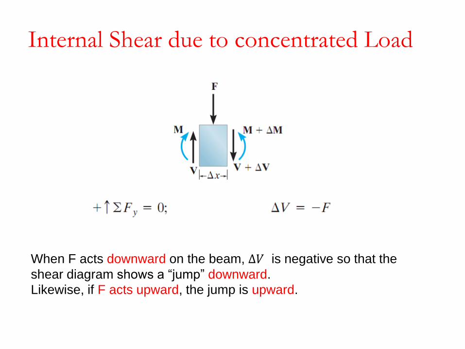
When F acts downward on the beam, ∆𝑉 is negative so that the
shear diagram shows a “jump” downward.
Likewise, if F acts upward, the jump is upward.
Internal Shear due to concentrated Load

If an external couple moment M’ is applied clockwise, ∆𝑀 is positive, so
that the moment diagram jumps downward,
and
when M’ acts counterclockwise, the jump must be upward.
Internal Moment due to concentrated moment

Example 8Draw shear force
and Bending
moment Diagram
B.M.D
S.F.D
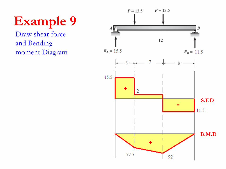
Example 9Draw shear force
and Bending
moment Diagram
S.F.D
B.M.D
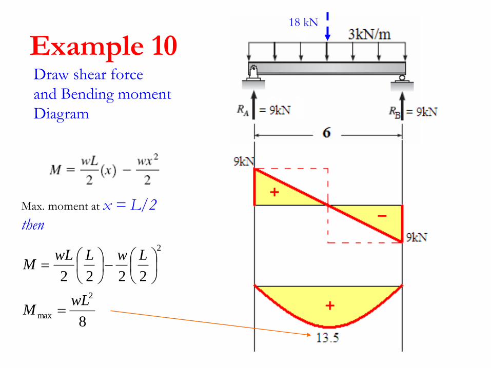
Example 10Draw shear force
and Bending moment
Diagram
18 kN
Max. moment at x = L/2
then
8
2222
2
max
2
wLM
LwLwLM
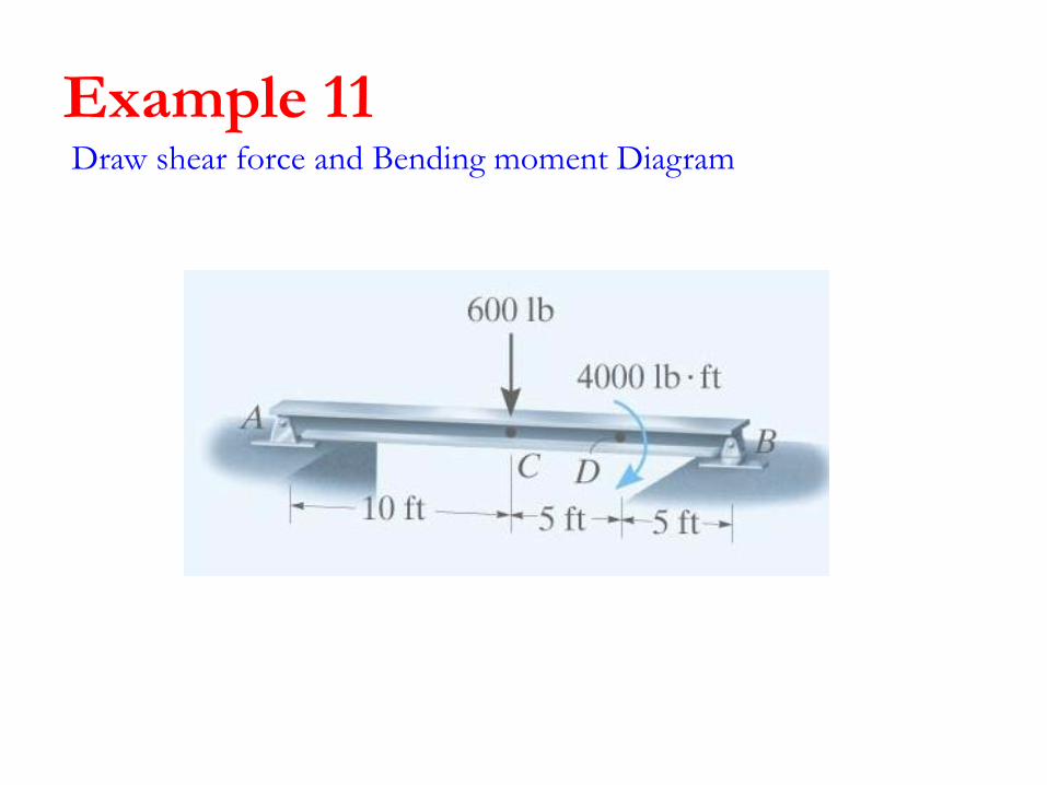
Example 11Draw shear force and Bending moment Diagram
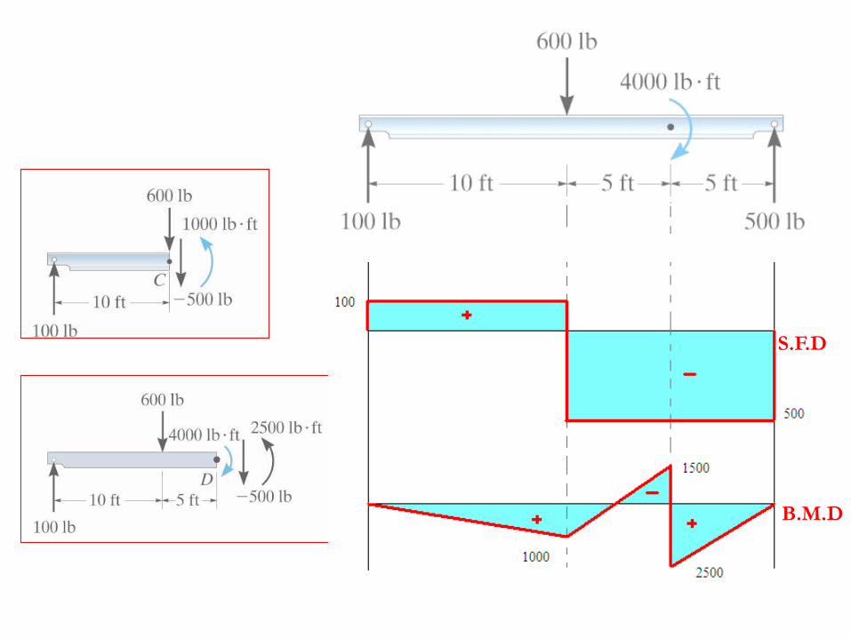
S.F.D
B.M.D
Draw shear force
and Bending
moment Diagram
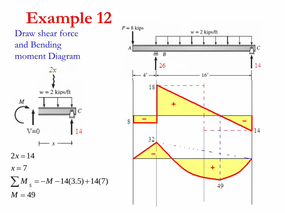
Example 12
49
)7(14)5.3(14
7
142
M
MM
x
x
S
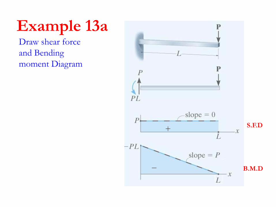
Example 13aDraw shear force
and Bending
moment Diagram
S.F.D
B.M.D
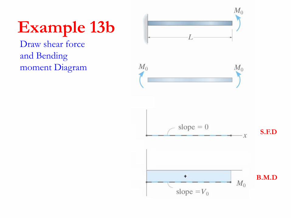
Example 13bDraw shear force
and Bending
moment Diagram
S.F.D
B.M.D
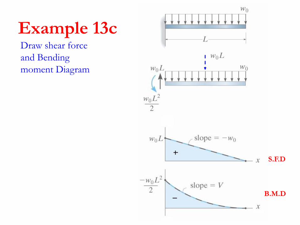
Example 13cDraw shear force
and Bending
moment Diagram
S.F.D
B.M.D

Example 13dDraw shear force
and Bending
moment Diagram

Draw shear force and Bending moment Diagram
Example 14
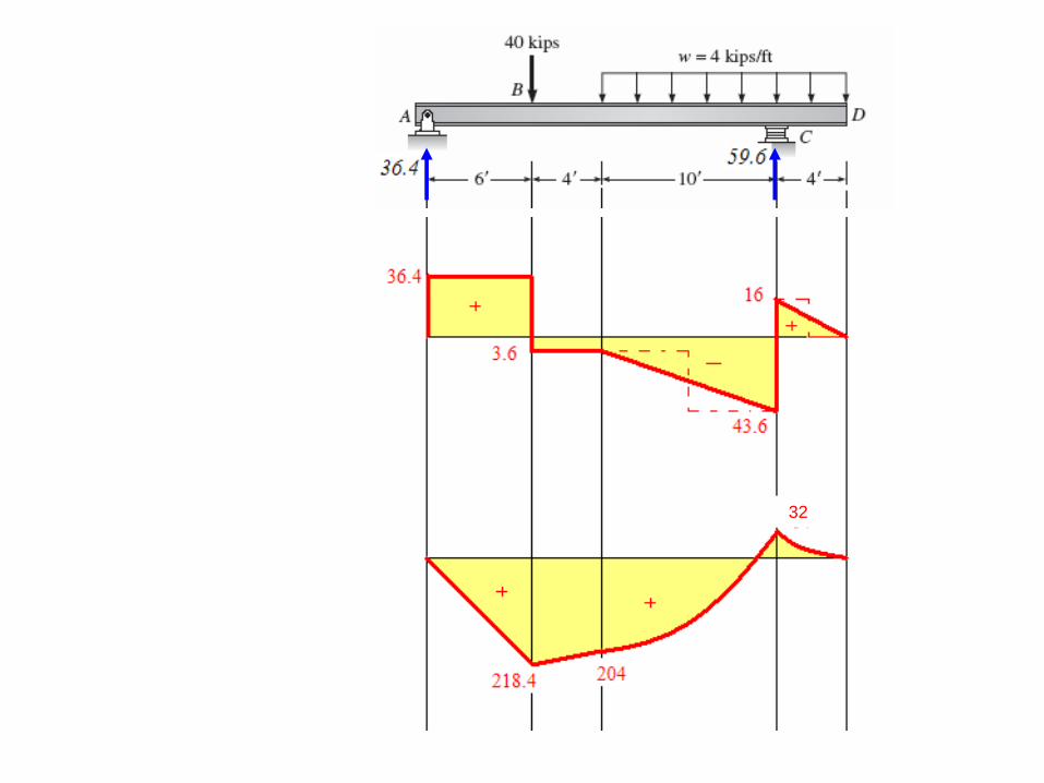
32
Draw shear force and Bending moment Diagram
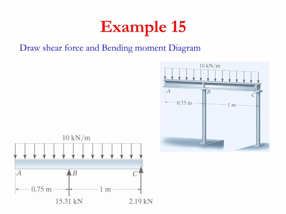
Example 15
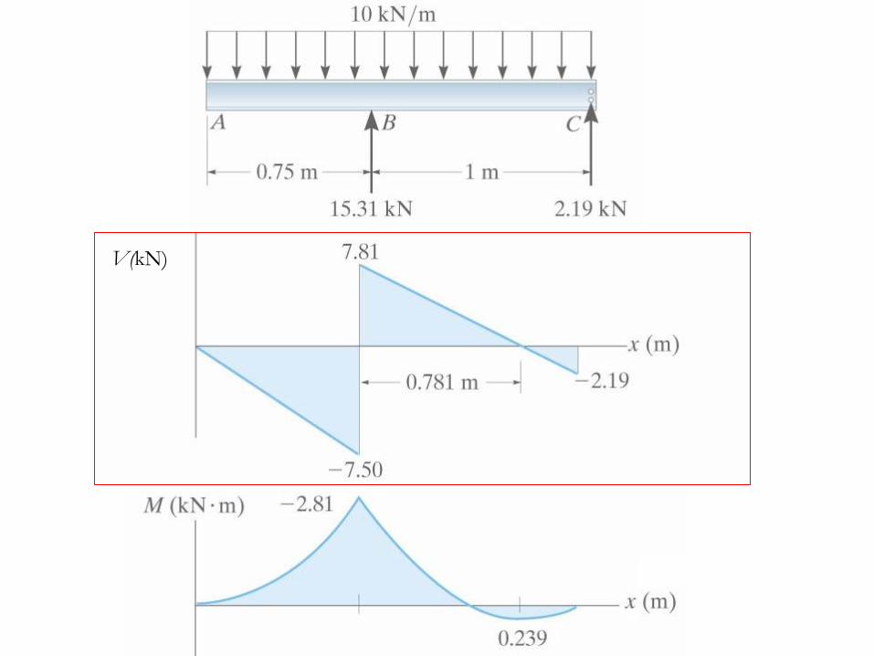
V(kN)
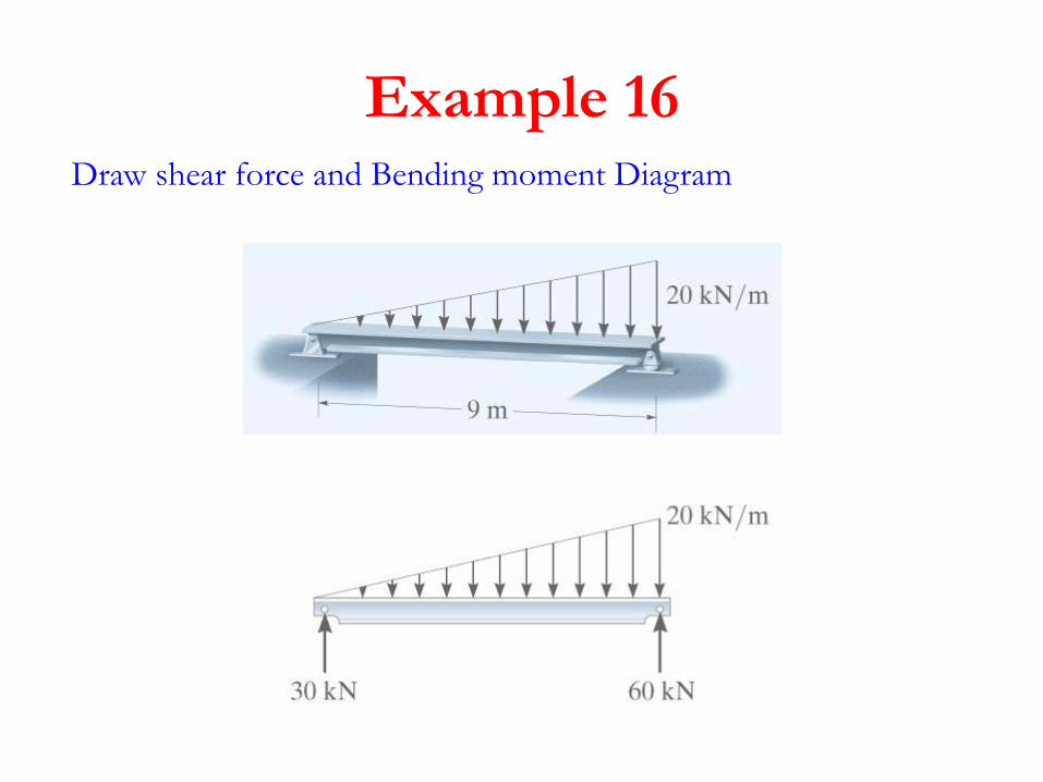
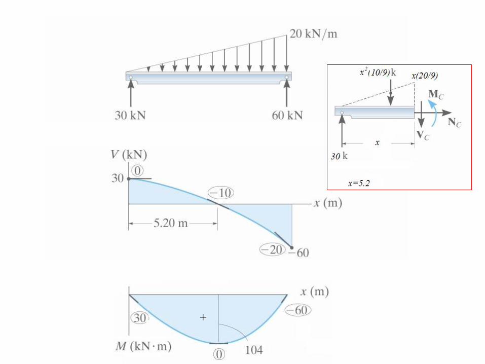
Example 16Draw shear force and Bending moment Diagram
+

Example 17Draw shear force
and Bending
moment Diagram
99

Example 18Draw shear force
and Bending
moment Diagram

Sketch BMD

Sketch BMD
Sketch BMD
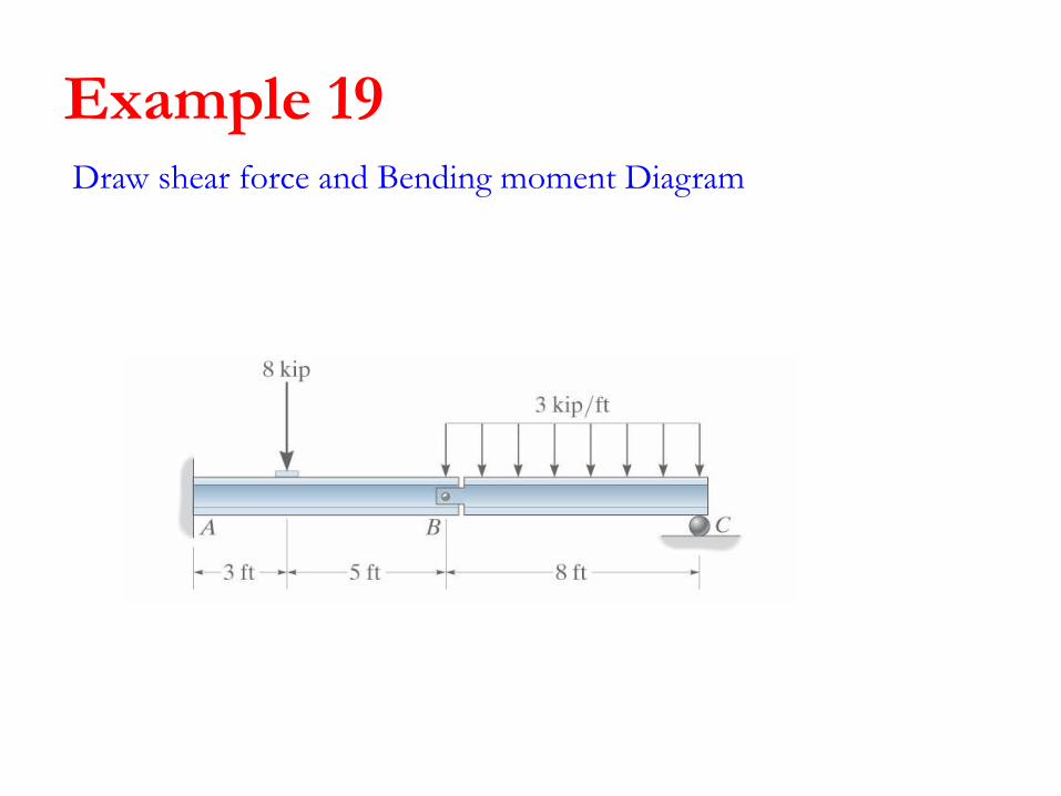
Example 19Draw shear force and Bending moment Diagram
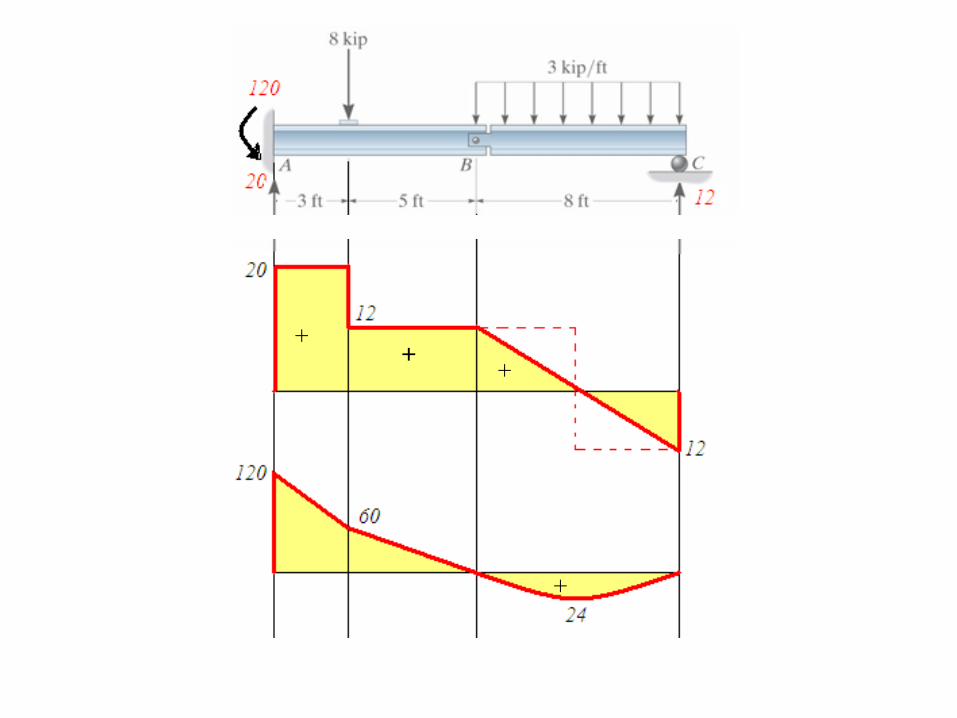
++
+
+
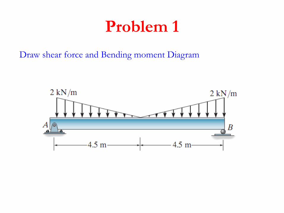
Problem 1
Draw shear force and Bending moment Diagram
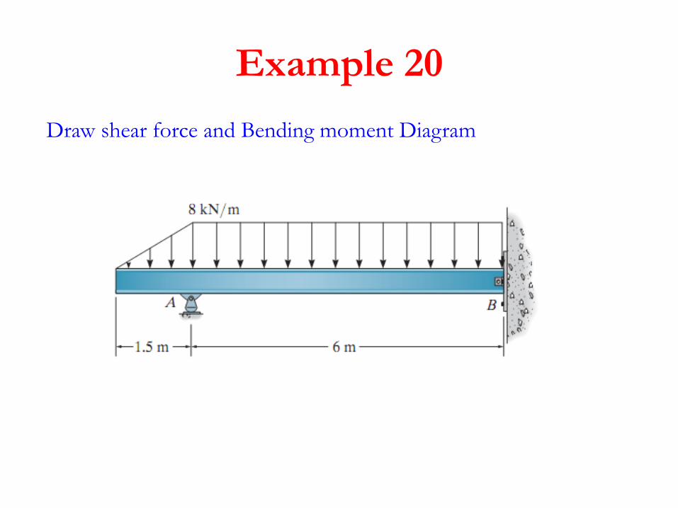
Example 20
Draw shear force and Bending moment Diagram
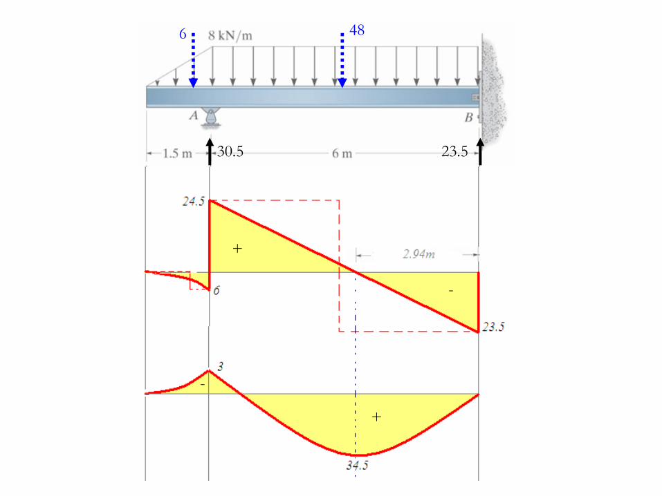
486
30.5 23.5
+
+
-
-

Example 21
Draw shear force and Bending moment Diagram
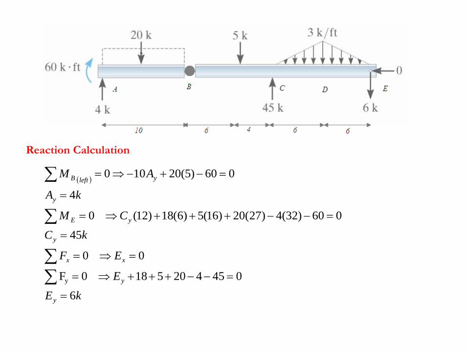
kE
E
EF
kC
CM
kA
AM
y
y
xx
y
yE
y
yleftB
6
045420518 0F
0 0
45
060)32(4)27(20)16(5)6(18)12( 0
4
060)5(20100
y
Reaction Calculation
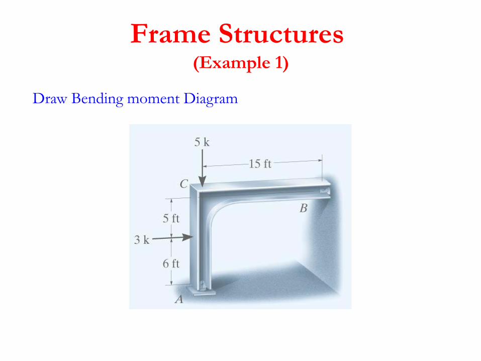
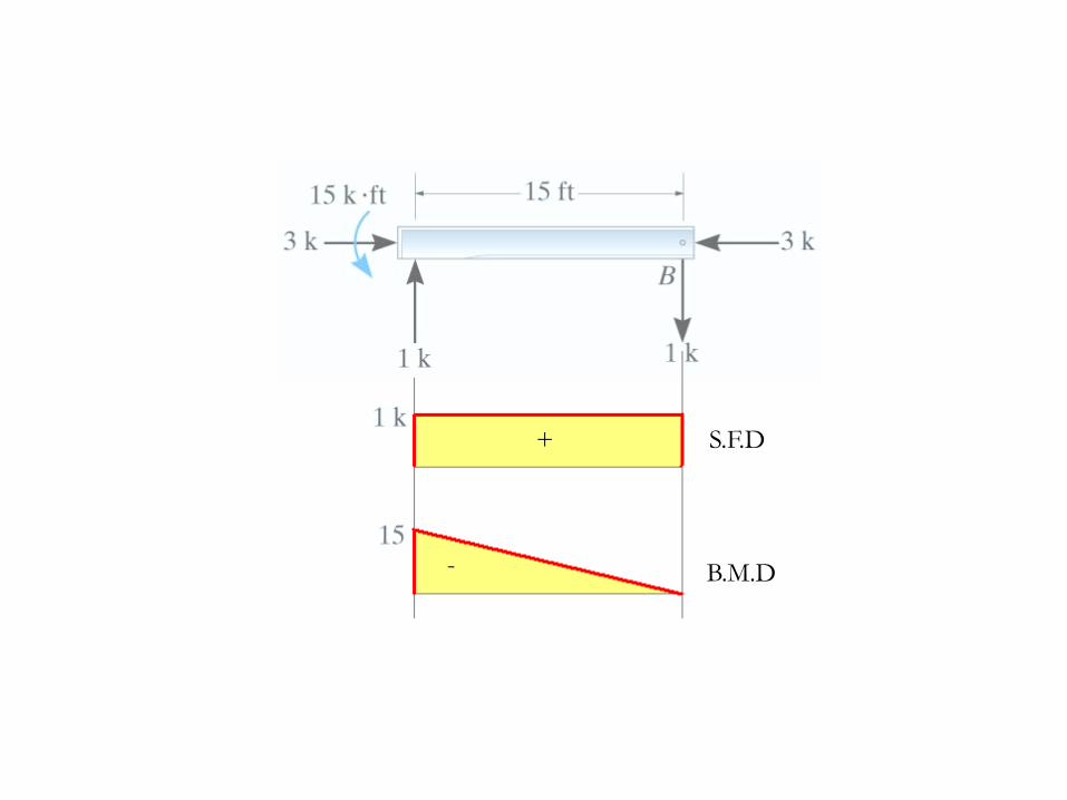
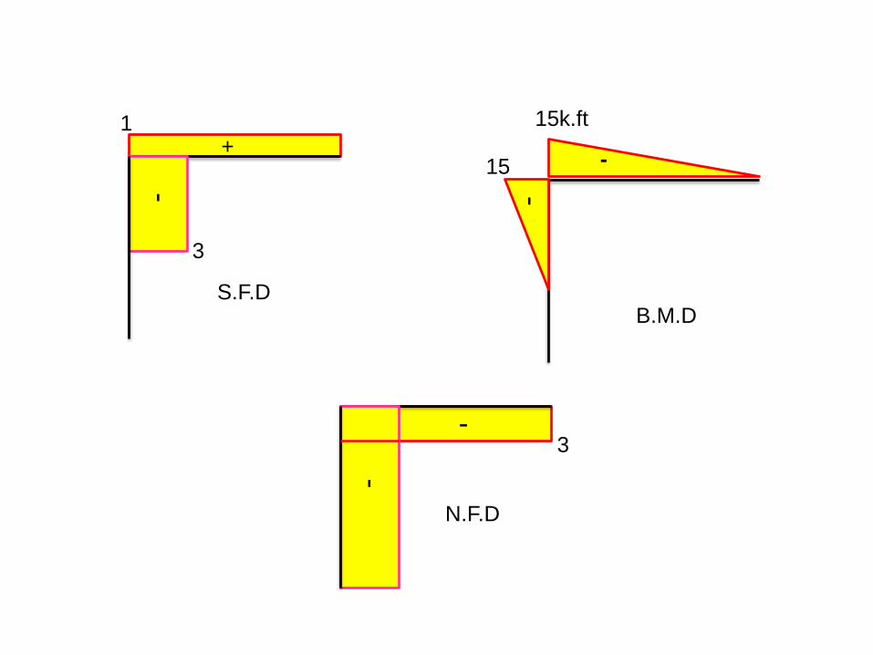
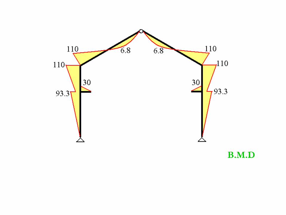
Frame Structures (Example 1)
Draw Bending moment Diagram
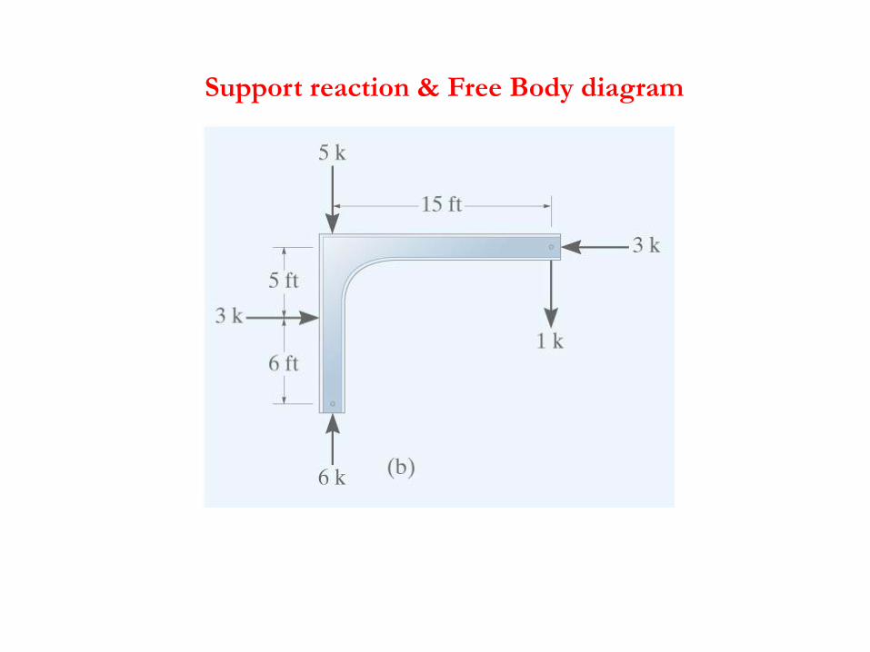
Support reaction & Free Body diagram

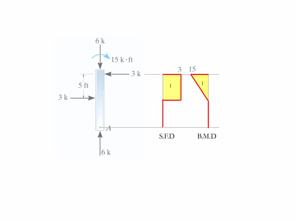
_ _
S.F.D B.M.D
+
-
S.F.D
B.M.D
-
B.M.D
-
15k.ft
15+
-
S.F.D
3
1
-
N.F.D
3-
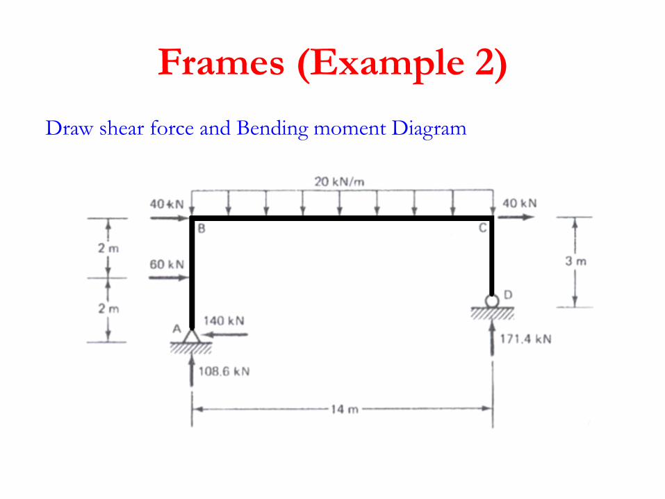
Frames (Example 2)
Draw shear force and Bending moment Diagram
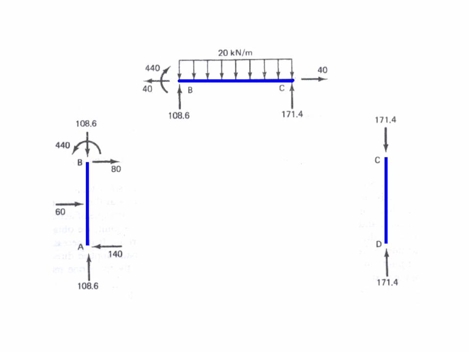

N.F.D
S.F.D
B.M.DN.F.D S.F.DB.M.D
N.F.D
+
+
+
_
+
+
-
-
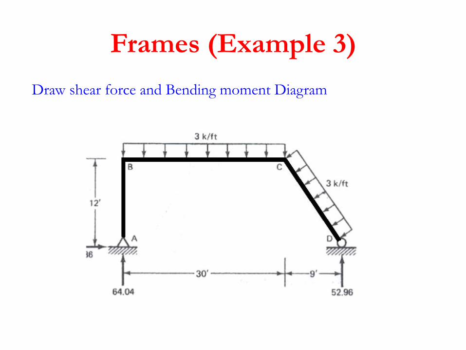
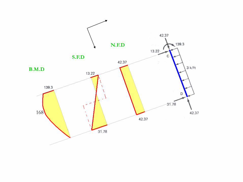
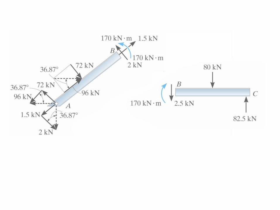
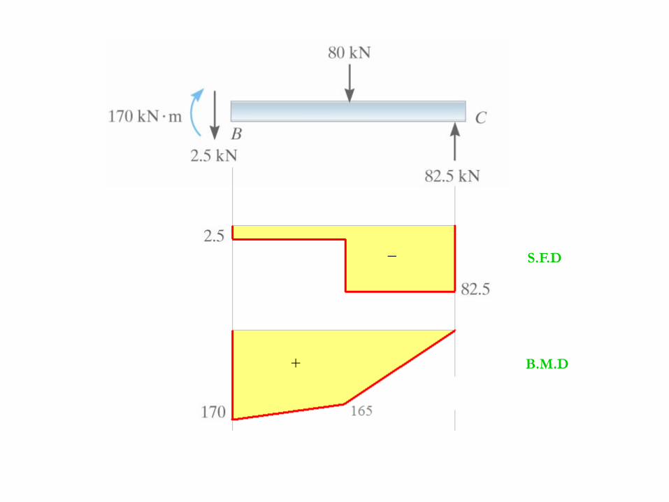
Frames (Example 3)
Draw shear force and Bending moment Diagram
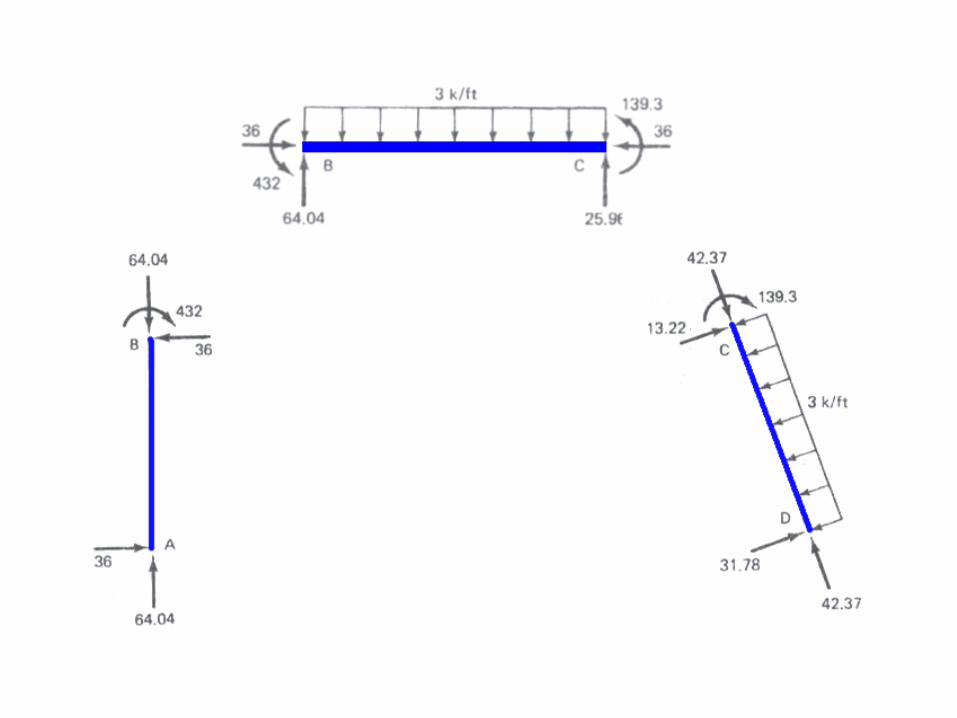
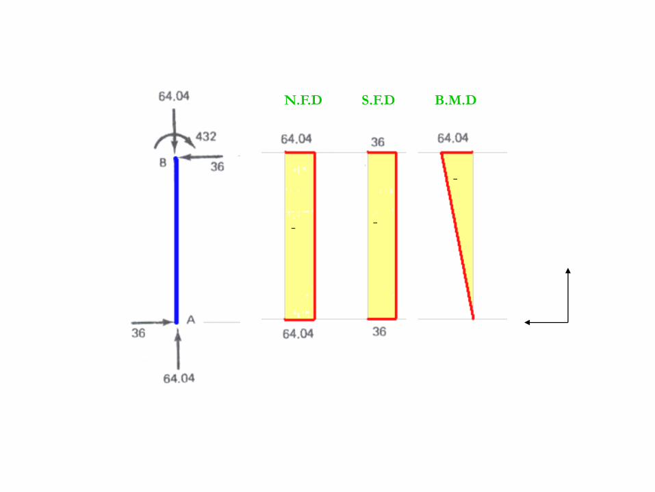
B.M.DN.F.D S.F.D
-
--
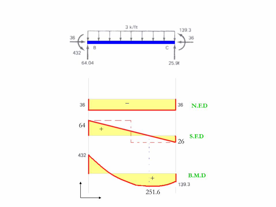
_
+
+
N.F.D
S.F.D
B.M.D
251.6
64
26
B.M.D
N.F.D
S.F.D
168

S.F.D
B.M.D
168
432 139.3
251.6
432
36
64
26
13.22
31.78
+
_
_
+
_
_
+

Frames (Example 4)
Draw shear force and Bending moment Diagram

+
+
S.F.D
B.M.D
+
_ S.F.D
B.M.D
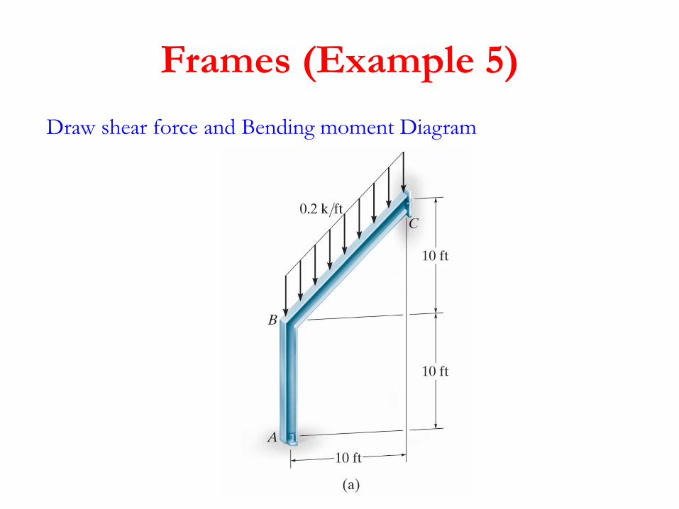
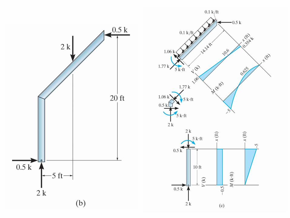
Frames (Example 5)
Draw shear force and Bending moment Diagram
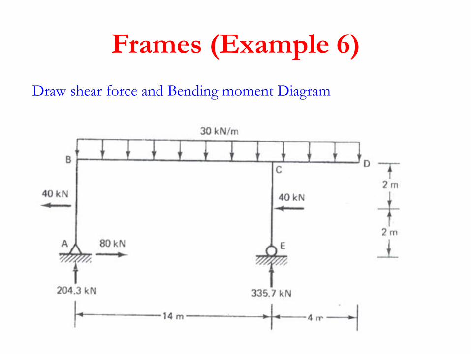
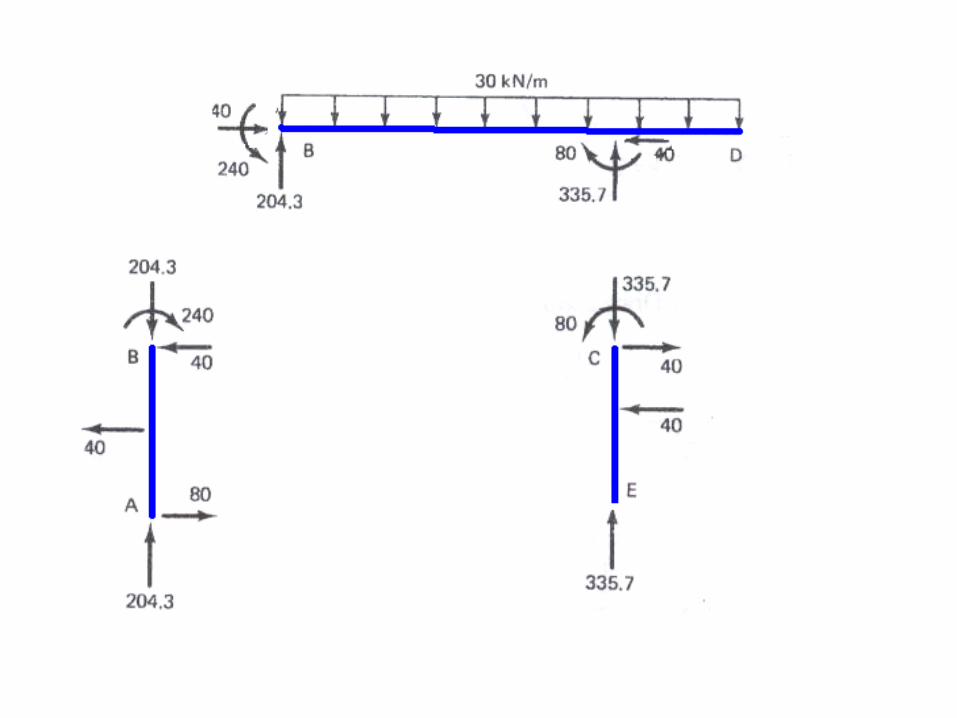
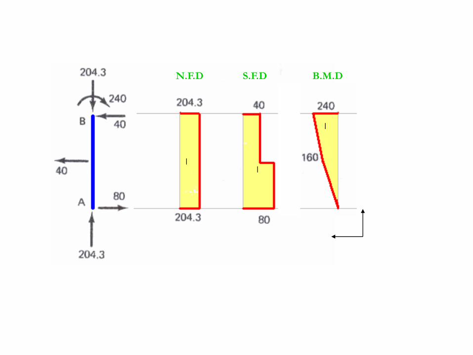
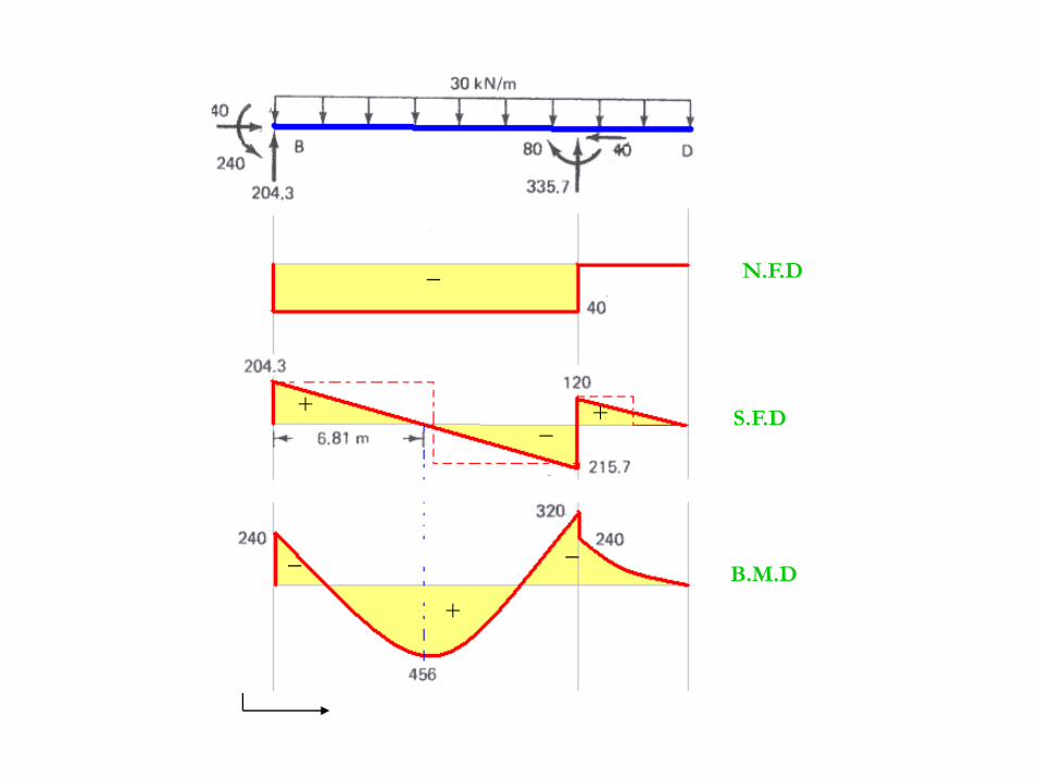
Frames (Example 6)
Draw shear force and Bending moment Diagram
_
_
_
N.F.D S.F.D B.M.D
+
_
+
_
__
+
N.F.D
S.F.D
B.M.D
_
+
_
N.F.DS.F.DB.M.D

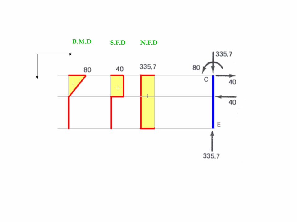
Problem 1
Draw Normal force, shear force and Bending moment Diagram
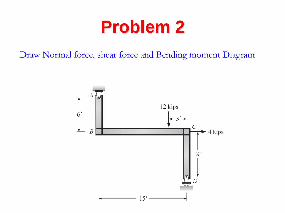
Problem 2
Draw Normal force, shear force and Bending moment Diagram
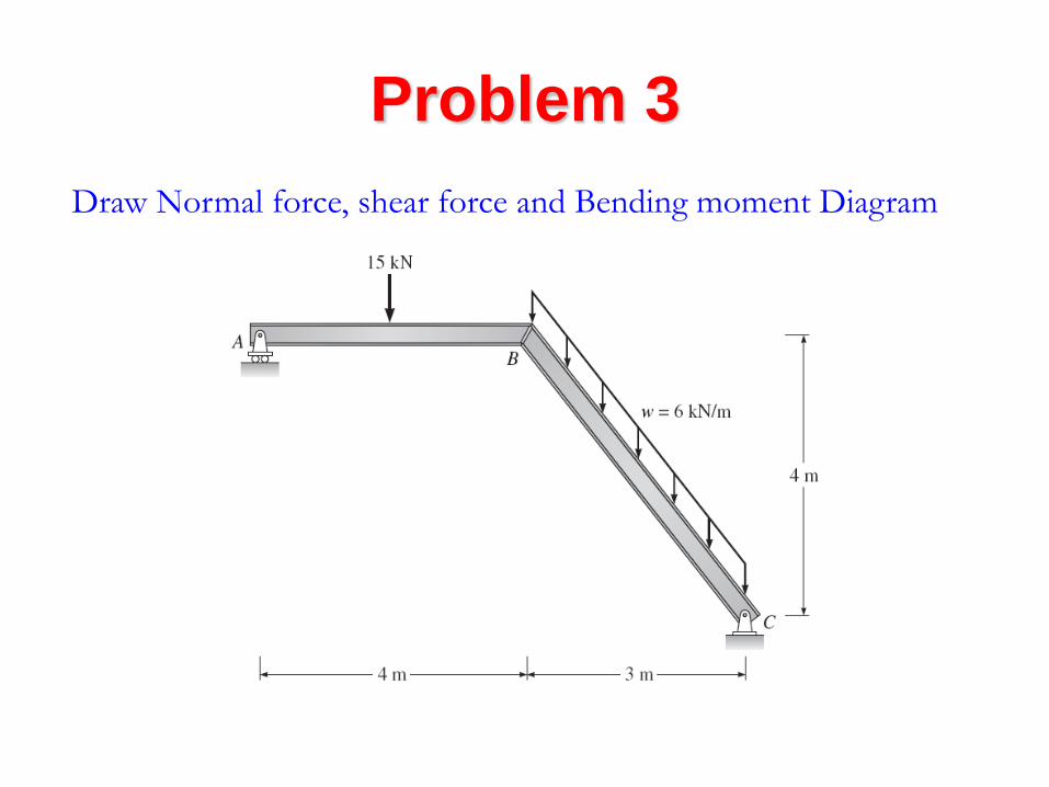
Problem 3
Draw Normal force, shear force and Bending moment Diagram
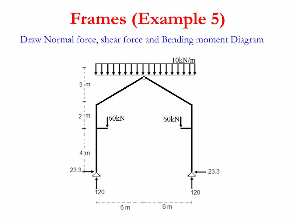
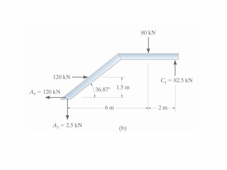
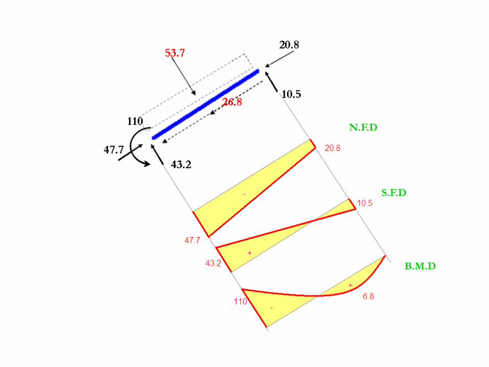
Frames (Example 5)Draw Normal force, shear force and Bending moment Diagram
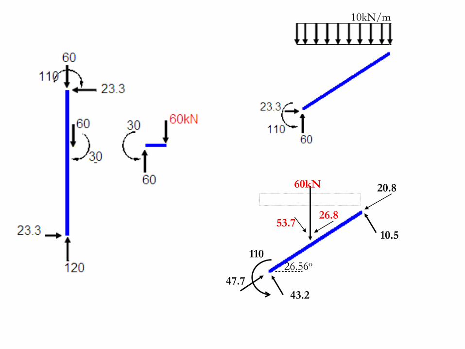
10kN/m
60kN
26.56o
53.726.8
47.7
43.2
10.5
20.8
110
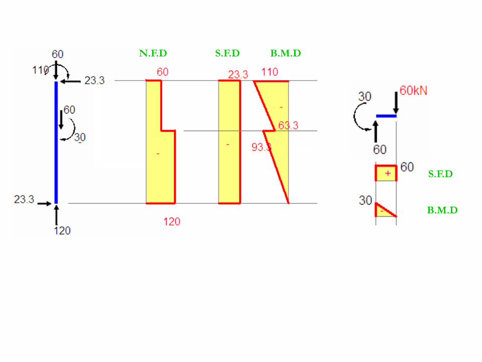
N.F.D S.F.D B.M.D
S.F.D
B.M.D
N.F.D
S.F.D
B.M.D
B.M.D
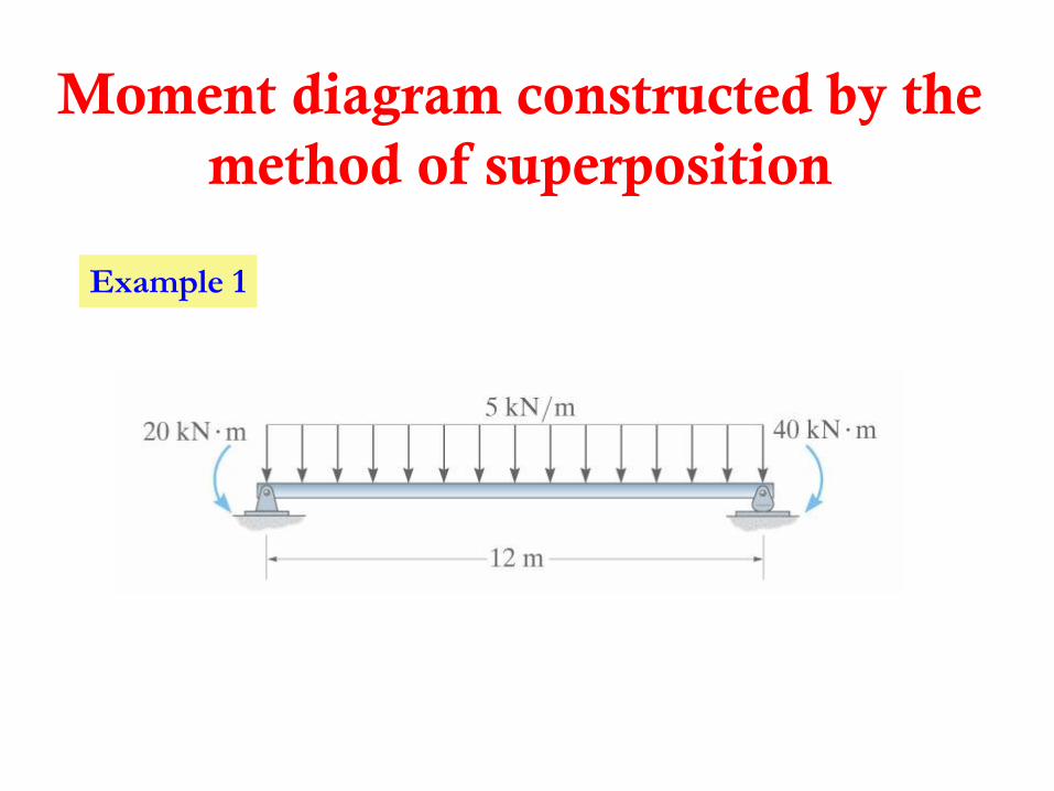
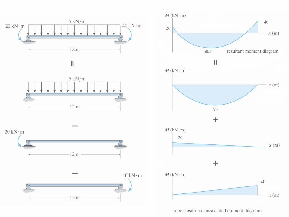
Moment diagram constructed by the
method of superposition
Example 1

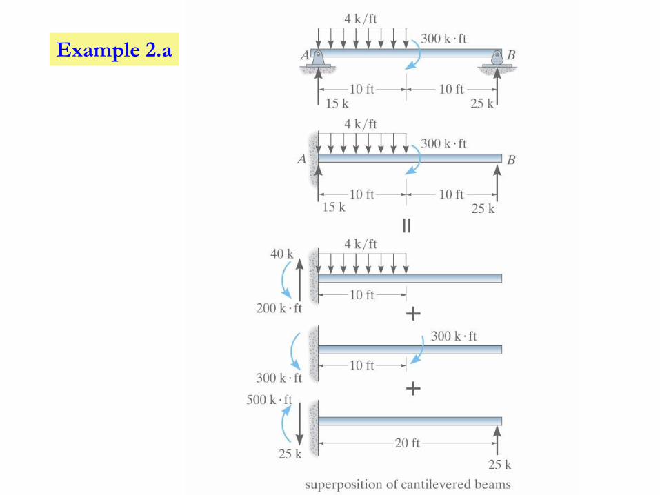
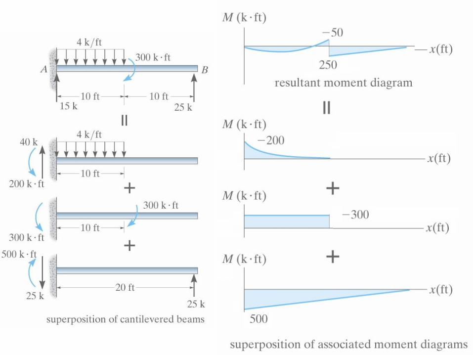
Example 2.a
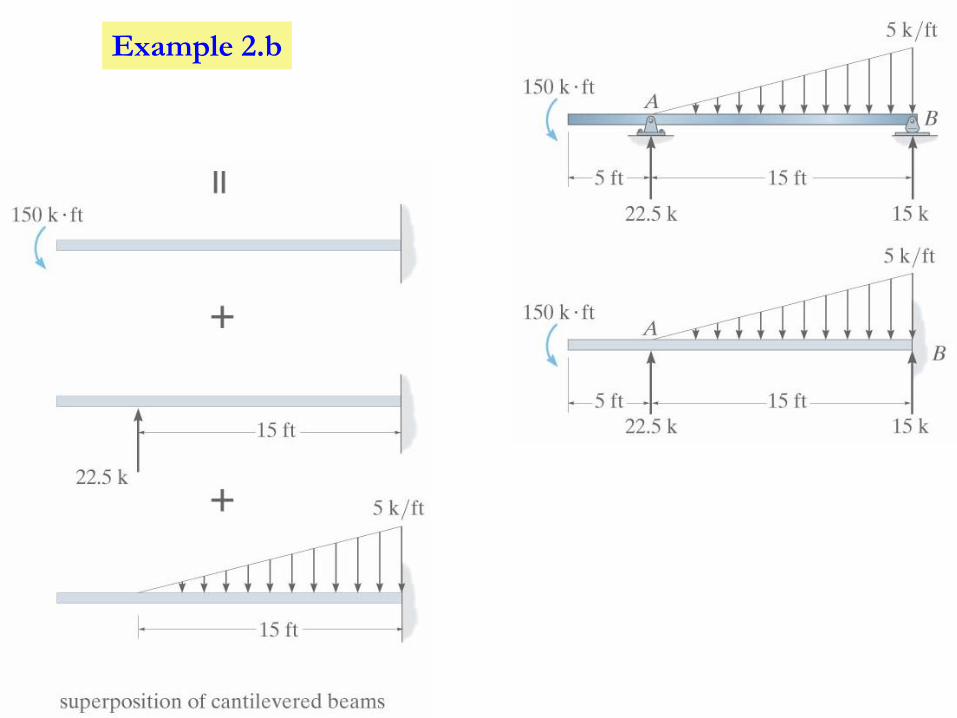
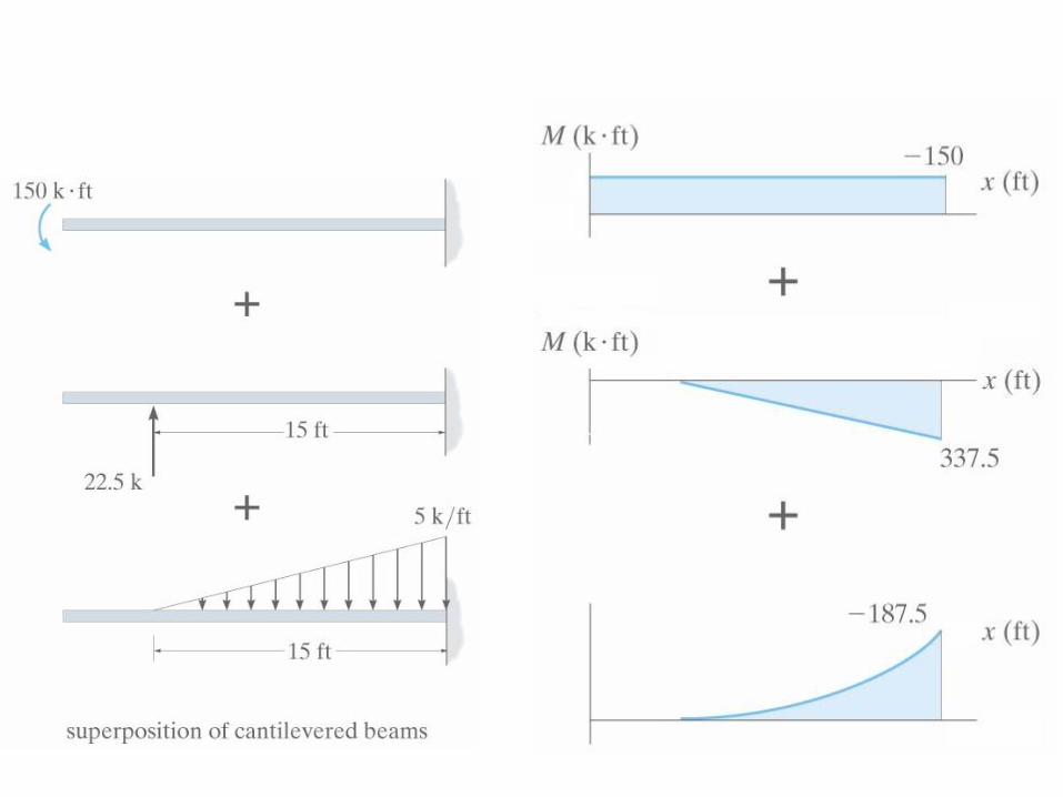
Example 2.b
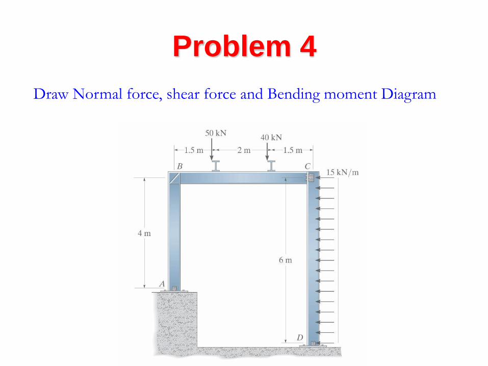
Problem 4
Draw Normal force, shear force and Bending moment Diagram
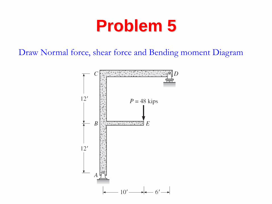
Problem 5
Draw Normal force, shear force and Bending moment Diagram

Problem 6
Draw Normal force, shear force and Bending moment Diagram