Embed Size (px)
Citation preview
1/13
Reference: 100-P-000096-EN-08
Issue: 02.2018
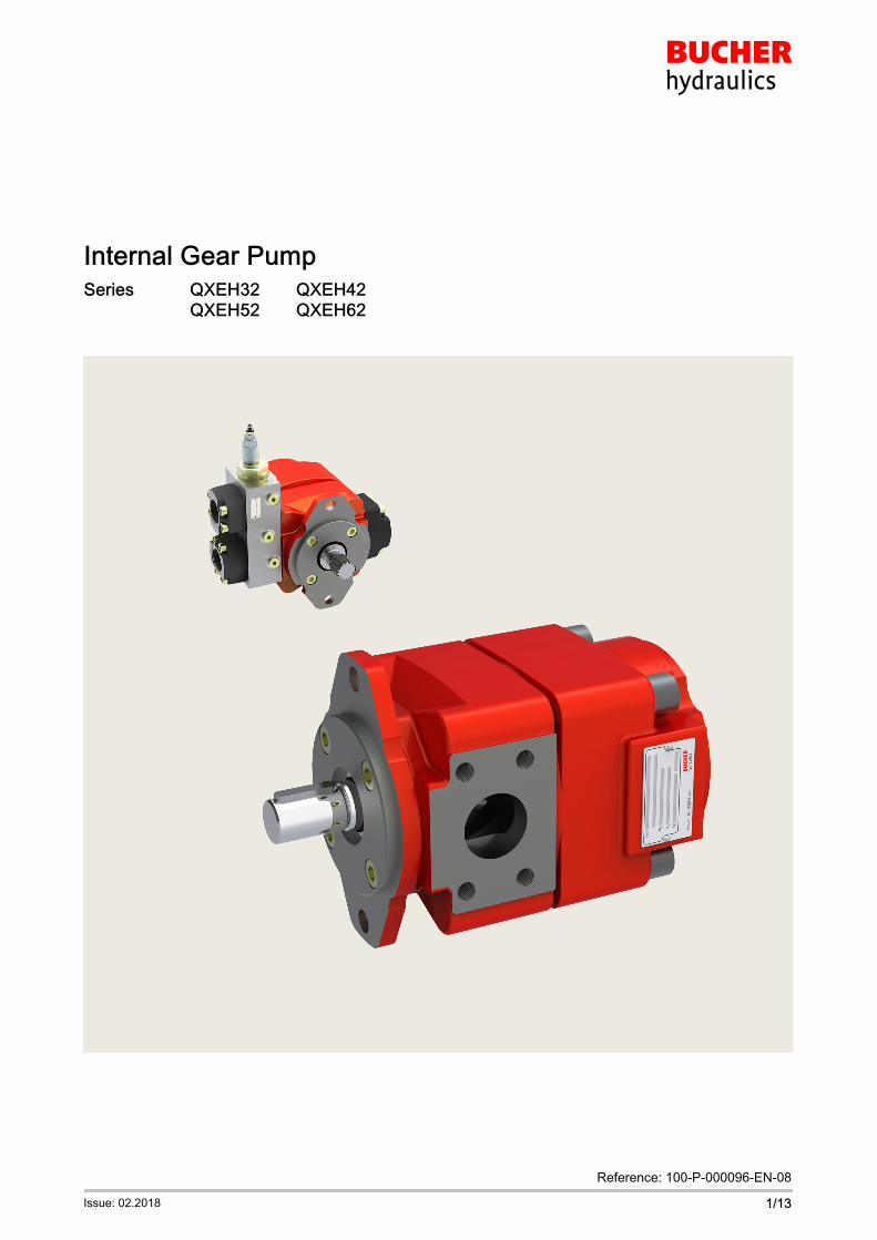
� Industrial model
� For variable-speed drives
Internal Gear PumpSeries QXEH32 QXEH42
QXEH52 QXEH62
100-P-000096-EN-08/02.2018
Internal Gear Pumps, QXEH.22/13
100-P-000096-EN-08/02.2018
Internal Gear Pumps, QXEH.23/13
Contents Page
1 General 5. . . . . . . . . . . . . . . . . . . . . . . . . . . . . . . . . . . . . . . . . . . . . . . . . . . . . . . . . . . . . . . . . . . . . . . . . . . .
1.1 Product description 5. . . . . . . . . . . . . . . . . . . . . . . . . . . . . . . . . . . . . . . . . . . . . . . . . . . . . . . . . . . .
1.2 Advantages 5. . . . . . . . . . . . . . . . . . . . . . . . . . . . . . . . . . . . . . . . . . . . . . . . . . . . . . . . . . . . . . . . . .
1.3 Application examples 5. . . . . . . . . . . . . . . . . . . . . . . . . . . . . . . . . . . . . . . . . . . . . . . . . . . . . . . . . .
2 Technical data 5. . . . . . . . . . . . . . . . . . . . . . . . . . . . . . . . . . . . . . . . . . . . . . . . . . . . . . . . . . . . . . . . . . . . . .
2.1 General technical data 5. . . . . . . . . . . . . . . . . . . . . . . . . . . . . . . . . . . . . . . . . . . . . . . . . . . . . . . . .
2.2 Main characteristics 6. . . . . . . . . . . . . . . . . . . . . . . . . . . . . . . . . . . . . . . . . . . . . . . . . . . . . . . . . . .
3 Characteristic curves 6. . . . . . . . . . . . . . . . . . . . . . . . . . . . . . . . . . . . . . . . . . . . . . . . . . . . . . . . . . . . . . . .
3.1 Noise level (Lp) 6. . . . . . . . . . . . . . . . . . . . . . . . . . . . . . . . . . . . . . . . . . . . . . . . . . . . . . . . . . . . . . .
3.2 Efficiencies [ 7. . . . . . . . . . . . . . . . . . . . . . . . . . . . . . . . . . . . . . . . . . . . . . . . . . . . . . . . . . . . . . . .
3.3 Operation with variable-speed drives 8. . . . . . . . . . . . . . . . . . . . . . . . . . . . . . . . . . . . . . . . . . . . .
3.4 Accelerations graph with QXEH62 8. . . . . . . . . . . . . . . . . . . . . . . . . . . . . . . . . . . . . . . . . . . . . . .
4 Dimensions 9. . . . . . . . . . . . . . . . . . . . . . . . . . . . . . . . . . . . . . . . . . . . . . . . . . . . . . . . . . . . . . . . . . . . . . . .
5 Ordering code 10. . . . . . . . . . . . . . . . . . . . . . . . . . . . . . . . . . . . . . . . . . . . . . . . . . . . . . . . . . . . . . . . . . . . . .
5.1 Standard configuration 10. . . . . . . . . . . . . . . . . . . . . . . . . . . . . . . . . . . . . . . . . . . . . . . . . . . . . . . . .
5.2 Options 10. . . . . . . . . . . . . . . . . . . . . . . . . . . . . . . . . . . . . . . . . . . . . . . . . . . . . . . . . . . . . . . . . . . . . .
6 Fluid 11. . . . . . . . . . . . . . . . . . . . . . . . . . . . . . . . . . . . . . . . . . . . . . . . . . . . . . . . . . . . . . . . . . . . . . . . . . . . . .
7 Fluid cleanliness 11. . . . . . . . . . . . . . . . . . . . . . . . . . . . . . . . . . . . . . . . . . . . . . . . . . . . . . . . . . . . . . . . . . . .
8 Operational reliability 11. . . . . . . . . . . . . . . . . . . . . . . . . . . . . . . . . . . . . . . . . . . . . . . . . . . . . . . . . . . . . . . .
9 Note 11. . . . . . . . . . . . . . . . . . . . . . . . . . . . . . . . . . . . . . . . . . . . . . . . . . . . . . . . . . . . . . . . . . . . . . . . . . . . . . .
10 Accessories 12. . . . . . . . . . . . . . . . . . . . . . . . . . . . . . . . . . . . . . . . . . . . . . . . . . . . . . . . . . . . . . . . . . . . . . . .
10.1 Pipe flanges - high pressure type (thread flange) 12. . . . . . . . . . . . . . . . . . . . . . . . . . . . . . . . . .
10.2 Pipe flanges - low pressure type (welding flange) 12. . . . . . . . . . . . . . . . . . . . . . . . . . . . . . . . . .
10.3 Bolt-on valves - SAE J518 code 61 / ISO 6162-1 pattern 13. . . . . . . . . . . . . . . . . . . . . . . . . . . .

100-P-000096-EN-08/02.2018
Internal Gear Pumps, QXEH.24/13
100-P-000096-EN-08/02.2018
Internal Gear Pumps, QXEH.25/13
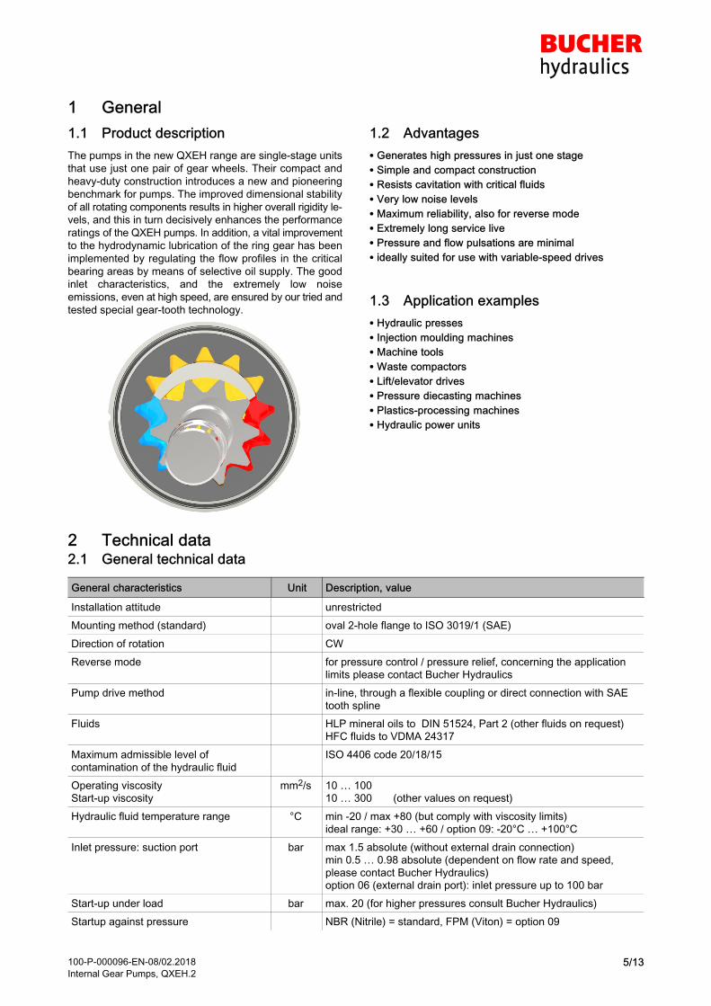
1 General
1.1 Product description
The pumps in the new QXEH range are single-stage units
that use just one pair of gear wheels. Their compact and
heavy-duty construction introduces a new and pioneering
benchmark for pumps. The improved dimensional stability
of all rotating components results in higher overall rigidity le
vels, and this in turn decisively enhances the performance
ratings of the QXEH pumps. In addition, a vital improvement
to the hydrodynamic lubrication of the ring gear has been
implemented by regulating the flow profiles in the critical
bearing areas by means of selective oil supply. The good
inlet characteristics, and the extremely low noise
emissions, even at high speed, are ensured by our tried and
tested special gear-tooth technology.
1.2 Advantages
� Generates high pressures in just one stage
� Simple and compact construction
� Resists cavitation with critical fluids
� Very low noise levels
� Maximum reliability, also for reverse mode
� Extremely long service live
� Pressure and flow pulsations are minimal
� ideally suited for use with variable-speed drives
1.3 Application examples
� Hydraulic presses
� Injection moulding machines
� Machine tools
� Waste compactors
� Lift/elevator drives
� Pressure diecasting machines
� Plastics-processing machines
� Hydraulic power units
2 Technical data2.1 General technical data
General characteristics Unit Description, value
Installation attitude unrestricted
Mounting method (standard) oval 2-hole flange to ISO 3019/1 (SAE)
Direction of rotation CW
Reverse mode for pressure control / pressure relief, concerning the application
limits please contact Bucher Hydraulics
Pump drive method in-line, through a flexible coupling or direct connection with SAE
tooth spline
Fluids HLP mineral oils to DIN 51524, Part 2 (other fluids on request)
HFC fluids to VDMA 24317
Maximum admissible level of
contamination of the hydraulic fluid
ISO 4406 code 20/18/15
Operating viscosity
Start-up viscosity
mm2/s 10 … 100
10 … 300 (other values on request)
Hydraulic fluid temperature range °C min -20 / max +80 (but comply with viscosity limits)
ideal range: +30 … +60 / option 09: -20°C … +100°C
Inlet pressure: suction port bar max 1.5 absolute (without external drain connection)
min 0.5 … 0.98 absolute (dependent on flow rate and speed,
please contact Bucher Hydraulics)option 06 (external drain port): inlet pressure up to 100 bar
Start-up under load bar max. 20 (for higher pressures consult Bucher Hydraulics)
Startup against pressure NBR (Nitrile) = standard, FPM (Viton) = option 09
100-P-000096-EN-08/02.2018
Internal Gear Pumps, QXEH.26/13
2.2 Main characteristics
IMPORTANT. The main characteristics are valid for mineral oils DIN 51524 with a viscosity of 20 to 50 mm2/s
Displace
ment
Flow rate
at speed
Maximum speed Code Continous pressure Torque Input
power
effective1450 min-1
p = 0 bar
Mineral
oilHFC
[bar]
continuous
[bar] 2)
intermittent
[cm3/rev] 1)
[cm3/rev]1)[l/min]
[rpm] 5)
[rpm] 5)
[rpm] 5)
[rpm] 5)
Mineral
oilHFC
Mineral
oilHFC [Nm] 3) [kW] 4)
10,0 14,5 4600 3600 QXEH32-010 250 220 280 240 39,8 6,0
12,6 18,3 4200 3300 QXEH32-012 250 220 280 240 50,2 7,6
15,6 22,6 3800 3000 QXEH32-016 250 220 280 240 62,1 9,4
20,3 29,5 4000 3200 QXEH42-020 250 220 280 240 81,2 12,3
25,1 36,4 3700 2900 QXEH42-025 250 220 280 240 99,9 15,2
32,3 46,8 3400 2700 QXEH42-032 250 220 280 240 129,0 19,6
39,1 56,9 3200 2500 QXEH52-040 250 220 280 240 156,4 23,7
50,3 73,2 3000 2400 QXEH52-050 250 220 280 240 201,4 30,6
63,4 92,1 2800 2200 QXEH52-063 250 220 280 240 253,6 38,5
79,8 116 2700 2100 QXEH62-080 250 220 280 240 319,3 48,5
100,5 146 2500 2000 QXEH62-100 250 220 280 240 402,1 61,0
124,2 181 2300 1800 QXEH62-125 250 220 280 240 496,8 75,4
159,7 232 2300 1800 QXEH62-160 160 130 200 170 447,0 67,9
1) Due to manufacturing tolerances, there may be slight variations in the
displacement.
2) Maximum intermittent pressure for a maximum of 20 seconds, but not for
more than 40% of the duty cycle.
3) Theoretical value at the maximum permitted continous pressure for
mineral oil.
4) Theoretical value at the maximum permitted continous pressure for
mineral oil at n = 1450 rpm
5) Maximum rated speeds for inlet pressure > 0.95 bar (abs.) and
outlet pressure > 100 bar.
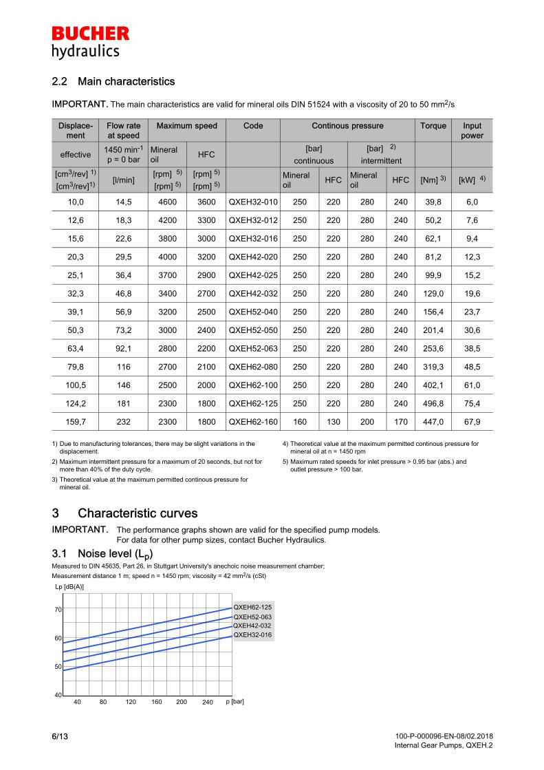
3 Characteristic curves
IMPORTANT. The performance graphs shown are valid for the specified pump models.
For data for other pump sizes, contact Bucher Hydraulics.
3.1 Noise level (Lp)Measured to DIN 45635, Part 26, in Stuttgart University's anechoic noise measurement chamber;
Measurement distance 1 m; speed n = 1450 rpm; viscosity = 42 mm2/s (cSt)
50
60
70
4040 80 120 160 200 240
23
Lp [dB(A)]
p [bar]
QXEH62-125
QXEH52-063
QXEH42-032
QXEH32-016
100-P-000096-EN-08/02.2018
Internal Gear Pumps, QXEH.27/13
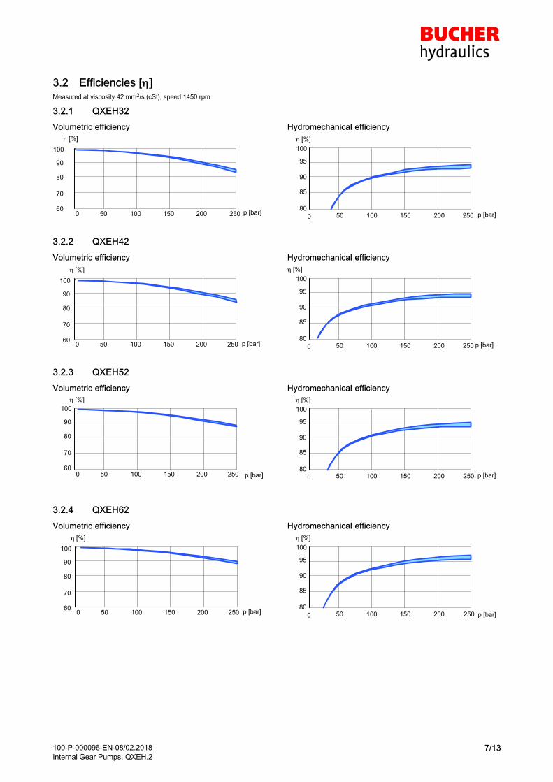
3.2 Efficiencies [��Measured at viscosity 42 mm2/s (cSt), speed 1450 rpm
3.2.1 QXEH32
Volumetric efficiency
[%]
p [bar]0 50 100 150 200 25060
80
100
70
90
Hydromechanical efficiency
[%]
p [bar]0 50 100 150 200 25080
90
100
85
95
3.2.2 QXEH42
Volumetric efficiency
[%]
p [bar]0 50 100 150 200 25060
80
100
70
90
Hydromechanical efficiency
[%]
p [bar]0 50 100 150 200 25080
90
100
85
95
3.2.3 QXEH52
Volumetric efficiency
[%]
p [bar]0 50 100 150 200 25060
80
100
70
90
Hydromechanical efficiency
[%]
p [bar]0 50 100 150 200 25080
90
100
85
95
3.2.4 QXEH62
Volumetric efficiency
[%]
p [bar]0 50 100 150 200 25060
80
100
70
90
Hydromechanical efficiency
[%]
p [bar]0 50 100 150 200 25080
90
100
85
95
100-P-000096-EN-08/02.2018
Internal Gear Pumps, QXEH.28/13
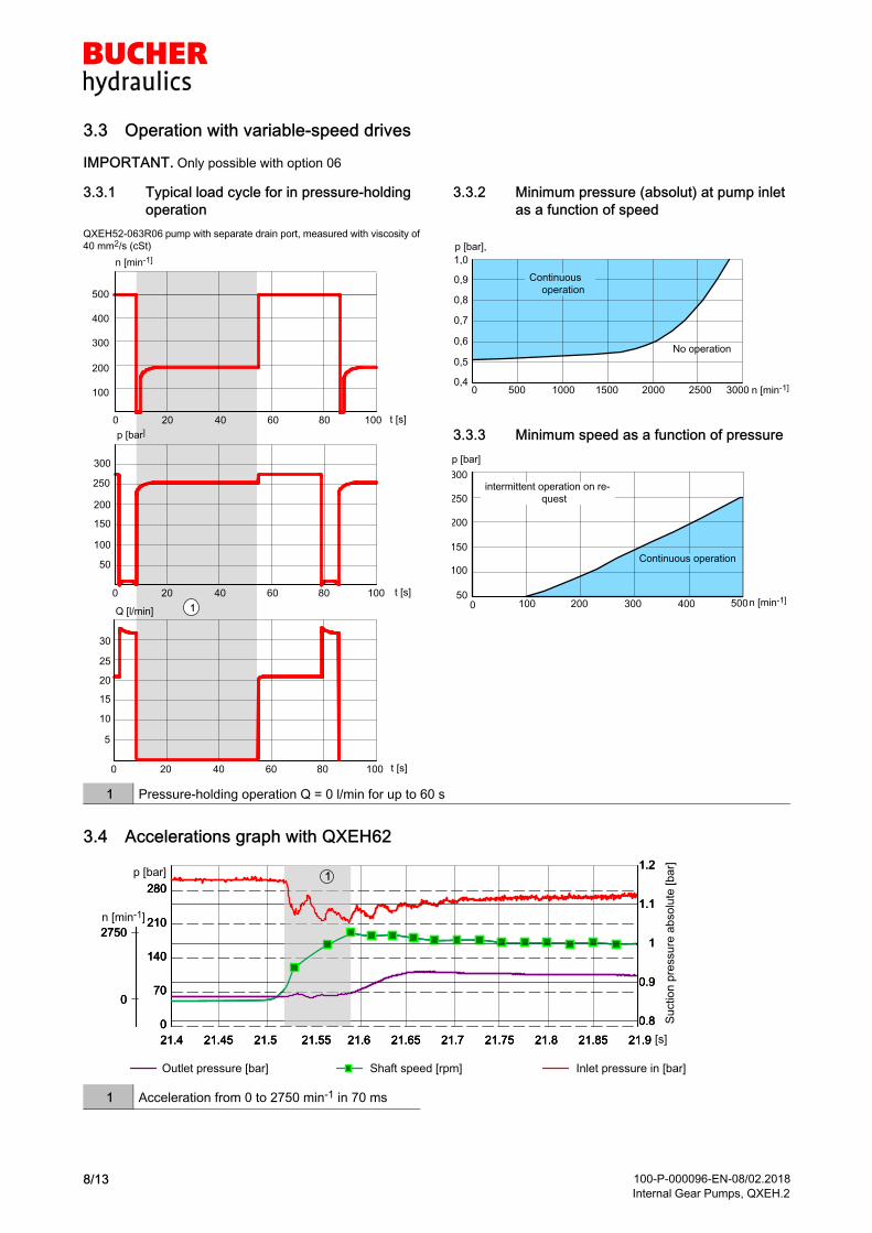
3.3 Operation with variable-speed drives
IMPORTANT. Only possible with option 06
3.3.1 Typical load cycle for in pressure-holding
operation
QXEH52-063R06 pump with separate drain port, measured with viscosity of
40 mm2/s (cSt)
0 20 40 60 80 100
n [min-1]
t [s]
250
0 20 40 60 80 100
p [bar]
t [s]
0 20 40 60 80 100
30
25
20
15
10
5
Q [l/min]
t [s]
1
500
400
100
200
300
50
100
150
200
300
3.3.2 Minimum pressure (absolut) at pump inlet
as a function of speed
0,4
0,5
0,6
0,7
0,8
0,9
1,0
0 500 1000 1500 2000 2500 3000
p [bar],
n [min-1]
Continuous
operation
No operation
3.3.3 Minimum speed as a function of pressure
300
250
200
150
100
500 100 200 300 400 500
p [bar]
n [min-1]
intermittent operation on re
quest
Continuous operation
1 Pressure-holding operation Q = 0 l/min for up to 60 s
3.4 Accelerations graph with QXEH62
Suction p
ressure
absolu
te [bar]
Outlet pressure [bar] Shaft speed [rpm] Inlet pressure in [bar]
21.4
0
70
140
210
280
0.8
0.9
1
1.1
1.2
21.45 21.5 21.55 21.6 21.65 21.7 21.75 21.8 21.921.85
0
2750
n [min-1]
21.4
0
70
140
210
280
0.8
0.9
1
1.1
1.2
21.45 21.5 21.55 21.6 21.65 21.7 21.75 21.8 21.921.85
0
2750
21.4 [s]
0
70
140
210
280
p [bar]
0.8
0.9
1
1.1
1.2
21.45 21.5 21.55 21.6 21.65 21.7 21.75 21.8 21.921.85
0
2750
1
1 Acceleration from 0 to 2750 min-1 in 70 ms
100-P-000096-EN-08/02.2018
Internal Gear Pumps, QXEH.29/13
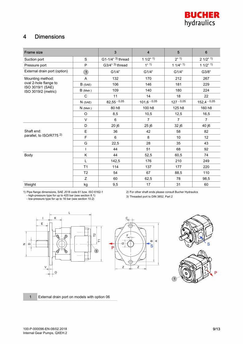
4 Dimensions
Frame size 3 4 5 6
Suction port S G1-1/4” 3) thread 1 1/2” 1) 2” 1) 2 1/2” 1)
Pressure port P G3/4” 3) thread 1” 1) 1 1/4” 1) 1 1/2” 1)
External drain port (option) 1 G1/4” G1/4“ G1/4“ G3/8“
Mounting method:
oval 2-hole flange to
ISO 3019/1 (SAE)ISO 3019/2 (metric)
A 132 170 212 267
B (SAE) 106 146 181 229
B (Metr.) 109 140 180 224
C 11 14 18 22
N (SAE) 82,55 - 0,05 101,6 - 0,05 127 - 0,05 152,4 - 0,05
N (Metr.) 80 h8 100 h8 125 h8 160 h8
O 8,5 10,5 12,5 16,5
V 6 7 7 7
Shaft end:
parallel, to ISO/R775 2)
D 20 j6 25 j6 32 j6 40 j6
E 36 42 58 82
F 6 8 10 12
G 22,5 28 35 43
I 44 51 68 92
Body K 44 52,5 60,5 74
L 142,5 176 210 249
T1 114 137 177 220
T2 54 67 88,5 110
Z 60 62,5 78 98,5
Weight kg 9,5 17 31 60
1) Pipe flange dimensions, SAE J518 code 61 bzw. ISO 6162-1
- high-pressure type for up to 420 bar (see section 8.1)
- low-pressure type for up to 16 bar (see section 10.2)
2) For other shaft ends please consult Bucher Hydraulics
3) Threaded port to DIN 3852, Part 2
K
1
P
B
SP
L
E
I
T1
DN
F
G
ZZ
T2
C
V
O
A
S
1
1 External drain port on models with option 06
100-P-000096-EN-08/02.2018
Internal Gear Pumps, QXEH.210/13
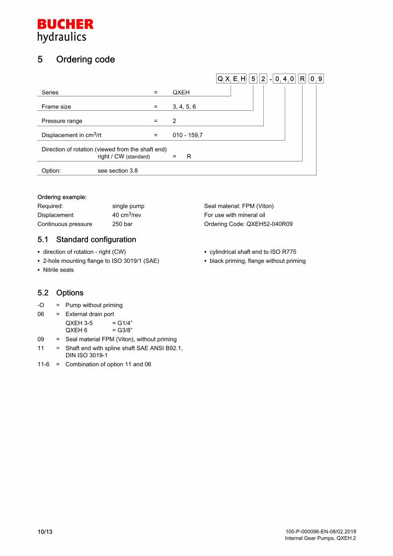
5 Ordering code
Series = QXEH
Frame size = 3, 4, 5, 6
Pressure range = 2
Displacement in cm3/rt = 010 - 159,7
Direction of rotation (viewed from the shaft end)
right / CW (standard) = R
Option: see section 3.8
Q X 0 4 0 R-5 2E H 0 9
Ordering example:
Required: single pump
Displacement 40 cm3/rev
Continuous pressure 250 bar
Seal material: FPM (Viton)
For use with mineral oil
Ordering Code: QXEH52-040R09
5.1 Standard configuration
� direction of rotation - right (CW)
� 2-hole mounting flange to ISO 3019/1 (SAE)
� Nitrile seals
� cylindrical shaft end to ISO R775
� black priming, flange without priming
5.2 Options
-O = Pump without priming
06 = External drain port
QXEH 3-5 = G1/4”
QXEH 6 = G3/8”
09 = Seal material FPM (Viton), without priming
11 = Shaft end with spline shaft SAE ANSI B92.1,
DIN ISO 3019-1
11-6 = Combination of option 11 and 06
100-P-000096-EN-08/02.2018
Internal Gear Pumps, QXEH.211/13
6 Fluid
The oil for QXEH products must have a minimum cleanli
ness level of 20/18/15 to ISO 4406.
We recommend the use of fluids that contain anti-wear
additives for operation with boundary lubrication. Fluids
without appropriate additives reduce the service life of
pumps and motors. The user is responsible for maintaining,
and regularly checking, the fluid quality. Bucher Hydraulics
recommends a Brugger EN/DIN 51347 load capacity > 30
N/mm2. This is particularly important in applications with
variable-speed drives and speeds < 1000 rpm.
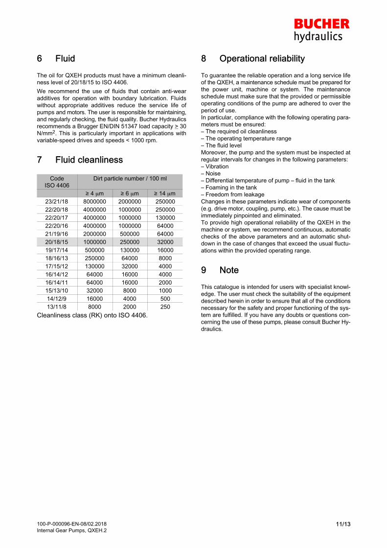
7 Fluid cleanliness
Code
ISO 4406
Dirt particle number / 100 ml
≥ 4 m ≥ 6 m ≥ 14 m
23/21/18 8000000 2000000 250000
22/20/18 4000000 1000000 250000
22/20/17 4000000 1000000 130000
22/20/16 4000000 1000000 64000
21/19/16 2000000 500000 64000
20/18/15 1000000 250000 32000
19/17/14 500000 130000 16000
18/16/13 250000 64000 8000
17/15/12 130000 32000 4000
16/14/12 64000 16000 4000
16/14/11 64000 16000 2000
15/13/10 32000 8000 1000
14/12/9 16000 4000 500
13/11/8 8000 2000 250
Cleanliness class (RK) onto ISO 4406.
8 Operational reliability
To guarantee the reliable operation and a long service life
of the QXEH, a maintenance schedule must be prepared for
the power unit, machine or system. The maintenance
schedule must make sure that the provided or permissible
operating conditions of the pump are adhered to over the
period of use.
In particular, compliance with the following operating para
meters must be ensured:
– The required oil cleanliness
– The operating temperature range
– The fluid level
Moreover, the pump and the system must be inspected at
regular intervals for changes in the following parameters:
– Vibration
– Noise
– Differential temperature of pump – fluid in the tank
– Foaming in the tank
– Freedom from leakage
Changes in these parameters indicate wear of components
(e.g. drive motor, coupling, pump, etc.). The cause must be
immediately pinpointed and eliminated.
To provide high operational reliability of the QXEH in the
machine or system, we recommend continuous, automatic
checks of the above parameters and an automatic shut
down in the case of changes that exceed the usual fluctu
ations within the provided operating range.
9 Note
This catalogue is intended for users with specialist knowl
edge. The user must check the suitability of the equipment
described herein in order to ensure that all of the conditions
necessary for the safety and proper functioning of the sys
tem are fulfilled. If you have any doubts or questions con
cerning the use of these pumps, please consult Bucher Hy
draulics.
100-P-000096-EN-08/02.2018
Internal Gear Pumps, QXEH.212/13
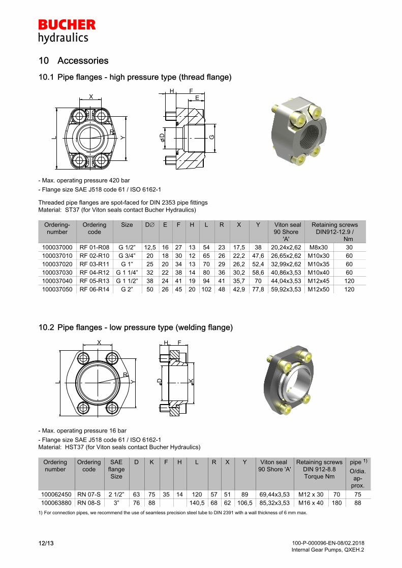
10 Accessories
10.1 Pipe flanges - high pressure type (thread flange)
HE
D GY
X
R
L
F
- Max. operating pressure 420 bar
- Flange size SAE J518 code 61 / ISO 6162-1
Threaded pipe flanges are spot-faced for DIN 2353 pipe fittings
Material: ST37 (for Viton seals contact Bucher Hydraulics)
Ordering
number
Ordering
code
Size D E F H L R X Y Viton seal
90 Shore
'A'
Retaining screws
DIN912-12.9 /
Nm
100037000 RF 01-R08 G 1/2” 12,5 16 27 13 54 23 17,5 38 20,24x2,62 M8x30 30
100037010 RF 02-R10 G 3/4” 20 18 30 12 65 26 22,2 47,6 26,65x2,62 M10x30 60
100037020 RF 03-R11 G 1” 25 20 34 13 70 29 26,2 52,4 32,99x2,62 M10x35 60
100037030 RF 04-R12 G 1 1/4” 32 22 38 14 80 36 30,2 58,6 40,86x3,53 M10x40 60
100037040 RF 05-R13 G 1 1/2” 38 24 41 19 94 41 35,7 70 44,04x3,53 M12x45 120
100037050 RF 06-R14 G 2” 50 26 45 20 102 48 42,9 77,8 59,92x3,53 M12x50 120
10.2 Pipe flanges - low pressure type (welding flange)
L Y
R
X
D K
FH
- Max. operating pressure 16 bar
- Flange size SAE J518 code 61 / ISO 6162-1
Material: HST37 (for Viton seals contact Bucher Hydraulics)
Ordering
number
Ordering
code
SAE
flange
Size
D K F H L R X Y Viton seal
90 Shore 'A'
Retaining screws
DIN 912-8.8
Torque Nm
pipe 1)
O/dia.
approx.
100062450 RN 07-S 2 1/2” 63 75 35 14 120 57 51 89 69,44x3,53 M12 x 30 70 75
100063880 RN 08-S 3” 76 88 140,5 68 62 106,5 85,32x3,53 M16 x 40 180 88
1) For connection pipes, we recommend the use of seamless precision steel tube to DIN 2391 with a wall thickness of 6 mm max.

100-P-000096-EN-08/02.2018
Internal Gear Pumps, QXEH.213/13
10.3 Bolt-on valves - SAE J518 code 61 / ISO 6162-1 pattern
Pressure relief valve Pressure relief valve
solenoid control
Accomulator charging valve
A DFSG A DAS
G AGSF
P T
M
Z
P T
M
Z
P T
M
Z
Technical data sheet
100-P-000123-
Technical data sheet
100-P-000119-
Technical data sheet
100-P-0000124-
10.3.1 Examples for Bolt-on valves, mounted on QX Internal Gear Pumps
Bolt-on valve with threaded ports
AGDF
Bolt-on valves with pipe flanges SAE1)
ASDF+RF
Bolt-on valve with pipe flanges SAE
+ RVSAE2)
ASDF+RF+RVSAE+DPSAE+ZPSAE
1) Pipe flange see chapter 8
2) Please ask BUCHER HYDRAULICS for check valves
IMPORTANT: For detailed informations on Bolt-on valves see www.bucherhydraulics.com
� 2018 by Bucher Hydraulics GmbH, D-79771 Klettgau
All rights reserved.
Data is provided for the purpose of product description only, and must not be construed as warranted characteristics in the legal sense. The
information does not relieve users from the duty of conducting their own evaluations and tests. Because the products are subject to continual
improvement, we reserve the right to amend the product specifications contained in this catalogue.
Classification: 410.100. 000