Embed Size (px)
Citation preview

Internal CuringHigh Performance Concrete
Presented By Jason Weiss
July 9th, 2020

Learning Objectives
• To define Internal Curing
• To understand the benefits of Internal Curing
• To review the most opportune applications for internal curing
• To understand how Internal Curing mixtures can be proportioned efficiently
• To review what properties and Internal Curing mixture can provide
• To discuss batching and quality control issues

Many of Us May Feel Like Homer

What Is Internal Curing
• Internal Curing (IC) has been defined in 2013 by the American Concrete Institute as: “a process by which the hydration of cement continues because of the availability of internal water that is not part of the mixing water.”
• This may be OK, but it may help us to have a bit of background on internal curing

Internal Curing Background
• Relatively new concept
• Philleo – Curing HPC needs to be different
• In the late 1990’s work in the US is focusing on demonstrating increased cracking is occurring in HPC and using things like SRA to control this
• In the late 1990’s work is underway in Denmark, Germany, Israel to develop the Internal Curing concepts tailed specifically for low w/c, high performance concrete

Original Internal Curing Approach
• Internal curing was originally very focusedon low w/cm systemsand overcoming self-desiccation and resulting autogenous shrinkage
• All concrete self-desiccates (develops vapor filled space) however this is not a problem in concrete with a higher w/c since this occurs in pores that are relatively large (as a result the curvature of the meniscus of the fluid in the pores is low and the capillary pressure and auto. shrinkage is low)

US Approach to Internal Curing
• In the US, we began looking for opportunities to use this in a wider range of concretes
• This has been applied to a wider range of more moderate concrete mixture designs and many additional benefits were examined
Castro et al. 2010
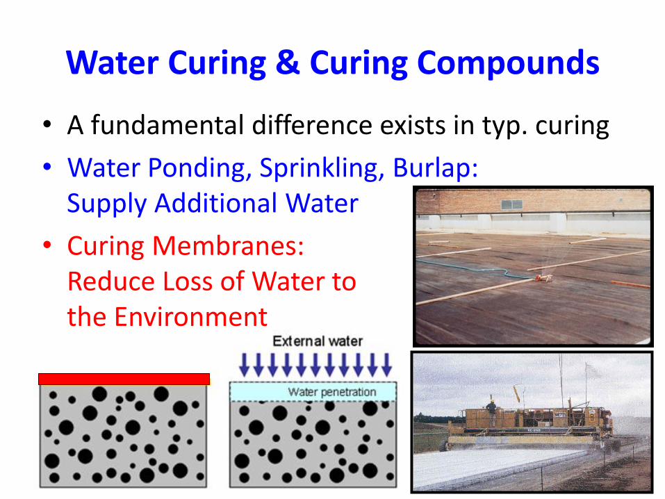
Water Curing & Curing Compounds
• A fundamental difference exists in typ. curing
• Water Ponding, Sprinkling, Burlap: Supply Additional Water
• Curing Membranes: Reduce Loss of Water tothe Environment

The Why of IC Simplified
• We want to do water curing (concrete 101) but in a different way. Instead of adding curing water from the outside, we will add it from inside the concrete.
• First, this is concrete 101 not magical or mysterious
• Second, this is designing the mixture to ‘automatically’ do the curing removing site step

The First Question That Comes UpDoes This Count Toward the W/C
• The water to cement ratio (w/c, by mass) is used as an indirect indicator of porosity
• Many concrete properties are related to ‘aspects’ of porosity, for example– Compressive Strength is Related to the Gel Space
Ratio (volume of gel/volume of gel + pores)
– Transport is inversely related to the product of pore volume and tortuosity (Formation Factor)
– Shrinkage is related to the emptying of small pores

The First Question That Comes Up
• Does the water in the LWA count as a part of the water to cement ratio

IC Water Doesn’t ‘Count’ in W/C
• Water ‘hidden’ in an inclusion (SAP, LWA, Cellulose) before set does not contribute to the porosity of the paste
• It is important to realize that once set occurs the addition of water can only fill pores (reduce shrinkage), and increase hydration (reducing transport and increasing strength)

What Does Water Curing Do
Sealed Water Curing

What are the Benefits of IC
• Reduced Autogenous Shrinkage
• Increased Cement Hydration
• Improved Curing when Short Term Cure Times are Permitted

What Not To Expect
• Internal Curing will not have a big impact on compressive strength – especially when cylinders are water cured (See Golias et al.)
• Internal Curing will not have a big impact on shrinkage measured using ASTM C-157. The reason is external drying empties pores until a certain size meniscus is reached (Radlinska et al. 2007), IC does change shrinkage rate and cracking potential
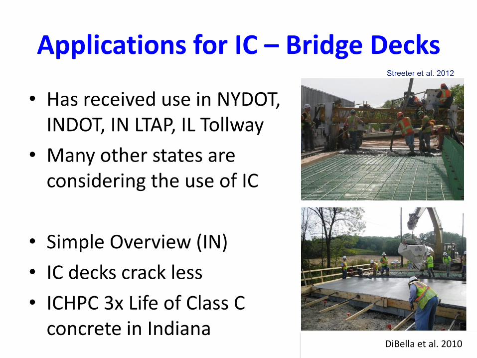
Applications for IC – Bridge Decks
• Has received use in NYDOT, INDOT, IN LTAP, IL Tollway
• Many other states are considering the use of IC
• Simple Overview (IN)
• IC decks crack less
• ICHPC 3x Life of Class C concrete in Indiana
DiBella et al. 2010

Applications for IC –Repairs, Early Opening
• Here we see an image from the city of west lafayette
• Internally cured patches were ‘equivalent to install’
• However they cracked less and had ‘water’ curingeven after openingto traffic
Bar
rett
et
al. 2
01
4

Applications for IC - Paving
• People are beginning to examine the use of internal curing for mainline paving and for concrete overlays
• Substantial CRCP pavement has been placed in TX and it has smaller crack widths
• IC may reduce curl (Rao and Darter 2013) which would impact design
• Ongoing area of research for CRCP and overlays

Role of Unit Weight
• In general the density of IC concrete is (5-10%)lower than conventional concrete
• Many agencies may benefit from two aspects when re-decking existing structures
• IC may enable higher performance concrete to be used
• Others may select to use light weight concrete which also has benefits in IC

Shifting Gears
http://i.imgur.com/I5SUjAi.webm

Mixture Proportioning
• General Concept
• Chemical shrinkage and the secret of 7
• How much LWA is used
• Volume of LWA as compared to sand
• A simple proportioning approach
• Aggregate Properties
• Moisture Corrections
• Plant Corrections

Proportioning Concept• Concept of proportioning mixtures for internal
curing is simple, other approaches exist
• Demand – Space created by chemical shrinkage (or other loss) – 0.064
• Supply – Water stored in the LWA
Supply Demand

Approach #1 - The Secret of 7
• 7 lbs water per 100 lbs cementious
• 6 bag mixture – 564 lb/yd3
• IC Water = 7*564/100 = 39.5 lb/yd3
• Assume Aggregate with 15% Absorption
• MassLWA-OD = 39.5/15% = 263 lb/yd3
• Very Good First Approximation

If One Replaces Sand with An Equal Volume of LWA

Simple Mixture Proportioning
• The majority of the time I believe that you will be asked to convert an existing mixture to an internally cured mixture
• This for example can be a paving mixture or a bridge deck mixture
• There is no reason to reinvent the wheel

Input Current Mixture Proportions

Calculating MLWA with other binder
• A good first approximation of chemical shrinkage in more complex binder systems (cement 0.07 ml/g)
• Other estimates0.064 ml/g (Cem), 0.12 ml/g (FA/Slag), 0.22 ml/g (SF)
• 20% Ash, 4.3% SF the CS is 17% higher
• Instead of 0.064 ml/g we would have a valueof 0.074 ml/g but as mentioned we used 0.07
Mass (lb) Mass (kg) CS Factor
IC Water
*Corrected
(lb)
IC Water
*Corrected
(kg)
Cement 435 197.73 0.07 30.45 13.84
Fly Ash 115 52.27 0.07 8.05 3.66
Silica Fume 25 11.36 0.07 1.75 0.80
Total 575 261.36 ~ 40.25 18.30
Mass (lb) Mass (kg) CS Factor
IC Water
*Corrected
(lb)
IC Water
*Corrected
(kg)
Cement 435 197.73 0.06 27.84 12.65
Fly Ash 115 52.27 0.10 11.50 5.23
Silica Fume 25 11.36 0.22 5.50 2.50
Total 575 261.36 ~ 44.84 20.38
Mass (lb) Mass (kg) CS Factor
IC Water
*Corrected
(lb)
IC Water
*Corrected
(kg)
Cement 435 197.73 0.06 27.84 12.65
Fly Ash 115 52.27 0.12 13.80 6.27
Silica Fume 25 11.36 0.22 5.50 2.50
Total 575 261.36 ~ 47.14 21.43
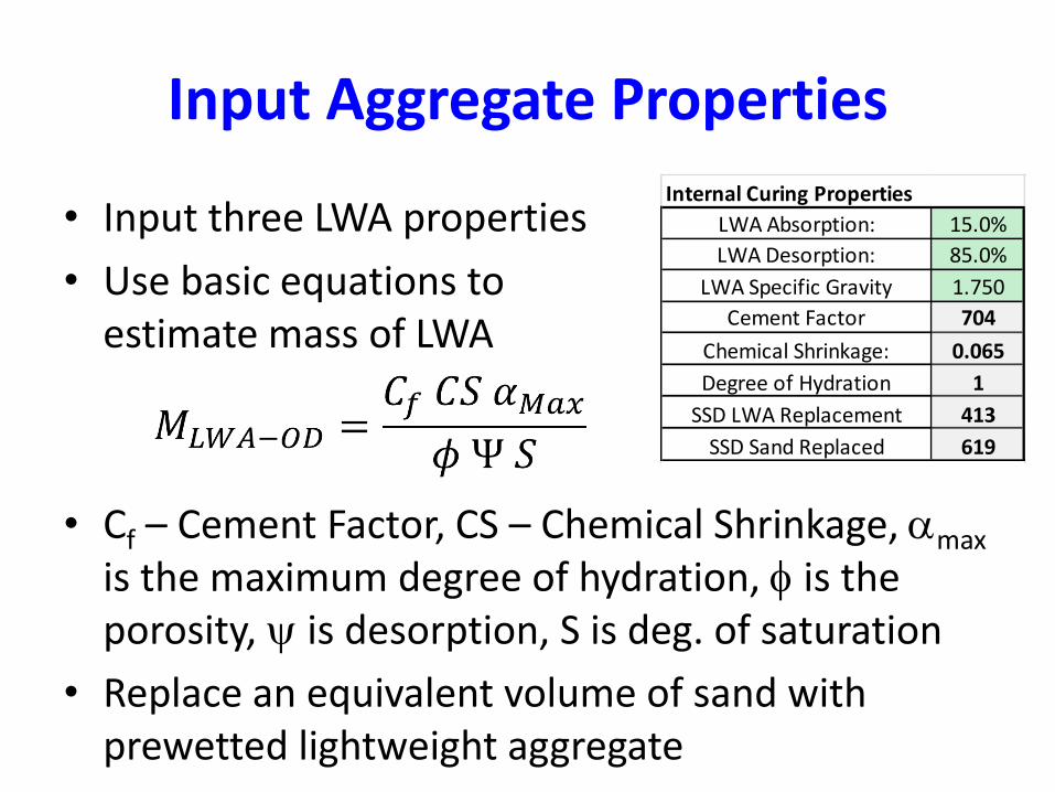
Input Aggregate Properties
• Input three LWA properties
• Use basic equations to estimate mass of LWA
• Cf – Cement Factor, CS – Chemical Shrinkage, amax
is the maximum degree of hydration, f is the porosity, y is desorption, S is deg. of saturation
• Replace an equivalent volume of sand withprewetted lightweight aggregate
LWA Absorption: 15.0%
LWA Desorption: 85.0%
LWA Specific Gravity 1.750
Cement Factor 704
Chemical Shrinkage: 0.065
Degree of Hydration 1
SSD LWA Replacement 413
SSD Sand Replaced 619
Internal Curing Properties

Calculation is Automatic
Materials Weight SG (SSD) Volume, ft3
Cement 564 3.15 2.869
GGBFS 115 2.99 0.616
Fly Ash 0 2.64 0.000
Silica Fume 25 2.2 0.182
Sand 591 2.623 3.613
Lightweight Aggregate 413 1.750 3.780
Coarse Aggregate 1 1700 2.763 9.860
Coarse Aggregate 2 0 2.763 0.000
Water 258 1 4.135
Air 0 0 1.755
Σ 3666 - 26.810
IC Mixture Design

Where to Find Aggregate Properties
• They can be measured or assumed to startMaterial
TypeProduction Location
Vacuum Water
Absorption*
Specific Gravity,
Oven Dry*
24 Hour Water
Absorption^
24 Hour
Desorption^
Specific Gravity,
24 Hour Calc.
Clay Erwinville, LA 26.8% 1.29 16.4% 92.4% 1.50
Clay Germany 27.0% 1.49 15.0%* 93.6%* 1.71
Clay Livingston, AL 35.5% 1.10 30.0% 97.5% 1.43
Clay Frazier Park, CA 19.1% 1.39 17.5% 95.2% 1.63
Shale Marquette, KS 22.5% 1.45 18.8% 96.2% 1.72
Shale New Market, MO 24.9% 1.50 14.9% 98.3% 1.72
Shale Brooklyn, IN 20.0% 1.56 12.4% 97.5% 1.75
Shale Cleveland, OH 18.6% 1.40 17.1% 97.3% 1.64
Shale Brooks, KY 22.0% 1.51 17.3% 96.4% 1.77
Shale Albany, NY 25.2% 1.38 17.4% 95.7% 1.62
Shale Boulder, CO 24.9% 1.46 19.0% 89.8% 1.74
Shale Streetman, TX 24.6% 1.48 20.1% 88.0% 1.78
Shale Coalville, UT 23.0% 1.49 19.7% 90.6% 1.78
Slate Buckingham, VA 18.6% 1.62 16.4% 97.1% 1.89
Slate Gold Hill, NC 11.4% 1.51 9.1% 97.5% 1.65
Slag Chicago, IL ~ 2.00& 10.5% 92.6% 2.21

Measuring Aggregate Properties
• Aggregate Moisture
• Surface Moisture
• Aggregate Absorp.
• Specific Gravity (Relative Density)
• Desorption
• Spreadsheet andStep by Step Process(Miller et al 2014)

Example Absorption
• Mass of Empty Bowl
• Mass of Prewetted LWAbefore centrifuge
• Mass of Prewetted LWAafter centrifuge
• Mass of Pan Used for oven drying
• Mass of pan and ovenDry Aggregate

Example Relative Density

Example Desorption
An Advantage of the Spreadsheet
• Aggregate summary is provided
LWA Absorption:
LWA Desorption:
LWA Specific Gravity:
Surface Moisure:

Quality Control and Batching

Measuring Air Content
• Volume Meter or Pressure Meter
Mixture:AE AirPres. AirVol.
(fl oz/cwt) (%) (%)
Mixture 1: Standard Class H 0.2 5.80% 5.25%
Mixture 2: TXI fine LWA (CS) 0.2 5.90% 4.75%
Mixture 3: TXI fine LWA double dose 0.3 5.00% 5.00%
Mixture 4: TXI coarse LWA (CS) 0.4 6.20% 5.75%
Mixture 5: TXI coarse LWA (100% repl) 0.4 7.00% 5.75%
Mixture 6: Buildex fine LWA (CS) 0.3 7.9% 6.5%
Mixture 7: IC Utelite fine LWA (CS) 0.3 6.8% 6.8%
Mixture: Class D 0.3 6.0% 5.8%
Mixture 9: TXI fine LWA (CS) – Class D 0.2 6.1% 5.8%
Jones et al. (2016)

Properties of IC Concrete
• There is an entire video of properties on the website mentioned at the end of this webinar
• Here I will hit some of the highlights
Go
lias
et a
l. 2
01
1
Water Curing Drying

Properties of IC Concrete
• Here we see no benefit when water cured
• However when cured in air the internally cured concrete behaves like water curing was used
Go
lias
et a
l. 2
01
1
Water Curing Drying

Properties - Transport
• Additional internal curing water reacts more binder to densify the system
• LWA reduces ITZ and reduces percolation
• At low w/c the capillary pores depercolate
Cas
tro
et
al. 2
01
1

Properties – Sealed Shrinkage
• As LWA replacement volume increases, autogenous shrinkage decreases
• 25.3% accounts for the CS volume
Henkensiefken et al. (2008)
Sealed
33.0%k
29.3%k
25.3%k
18.3%k
14.3%k
11.0%k
7.3%k
0.0%

Properties – Shrinkage Cracking
• Increasing the LWA volume decreases the potential for cracking
• For sealed samples as the volume approaches the CS replacement (25%) no cracking is observed
• Unsealed samples require a higher volume

Freeze-Thaw Behavior• Performance of lightweight bridge concrete
bridge decks is atleast as good as normal density concrete (Brown et al. 1985)
• Experiments have shown that plain and internally cured concrete behavesimilarly if they are properlyair entrained
• Want to be careful at early ages, and use a sufficiently low w/c where self-desiccation will pull water out of the LWA

Freeze-Thaw Behavior
• Here we can see the ASTM C 666 data
• The conventional concrete is fine as is the LWA with the water in the LWA = CS (Mix 2, 4)
• The 2x CS will leave water in the LWA
• The LWCA has excess water that has not beendrawn out of the LWA(too much IC water)
Jones et al. 2013

Influence of w/c and IC
• High w/c will not draw water from the LWA as fast as low w/c since the suction is higher low w/c
• May be susceptible to damage at early ages
Jones et al. 2013

Alkali Silica Reaction
• Shin et al. 2010 reported results for 5 systems
• Internal Curing Pros
– decreases porosity through hydration
– accommodation space allows gel to form without developing pressure
– dilution (replaces reactive aggregates)
• Internal Curing Cons
– Higher RH/moisture in paste would enable more ASR reaction to occur

Alkali Silica Reaction
• Reactive (R) – Most reactive and expansive
• Non Reactive Aggregate Replacement at 15 & 28% (m) –Reduces expansion due to dilution
• Internal Curing – LWA Replacement at 15 & 28% (N) –more effective even than non-reactive aggregate
• Hypothesis LWA provides space for expansive gel
• Recent work by Chang et al. examiningrole of pore solution
Shin et al. 2010

Conclusions – Part I
• IC – Is curing done from inside concrete
• IC uses LWA, SAP, cellulose
• IC improves hydration, reduces autogenousshrinkage, and improves short term curing
• IC demonstrated benefits in bridge decks and repairs … ongoing work look at pavements

Conclusions – Part II
• Basics of IC – 7 lb of water per 100 lb cement
• Mixture Design spreadsheet
• Importance of aggregate properties and aggregate moisture – Centrifuge test
• Plant corrections can be made – Moisture corrections and ‘plant weight corrections’
• IC improves properties
• IC is particularly well suited for HPC

Additional Resources http://cce.oregonstate.edu/internalcuring

Acknowledgements and Disclaimer
• These slides were developed as a part of a series for the Snyder Associates by Jason Weiss.
• These materials are provided as general information and do not constitute legal or other professional advice.
• Any use of this information in the design or selection of materials for practice should be approved by the project owner and engineer-of-record.