Embed Size (px)
Citation preview
Internal Combustion Internal Combustion Engines –Engines –The DieselThe Diesel

ObjectivesObjectives
• Uses for internal combustion engines
• Thermodynamic principles involved• Components and purposes of each• Operation of systems
• Two stroke engines• Four stroke engines
The Diesel is a HackerThe Diesel is a Hacker
Engine UsesEngine Uses
• Emergency Diesel Generators (EDG)• Propulsion
• Certain amphibious landing ships• Mine warfare ships• Patrol craft• Tug boats• Small boats• Outboard motors
Thermodynamic Thermodynamic PrinciplesPrinciples
• All internal combustion• Open cycle, heated engine
• Gasoline (Otto) engine• Spark ignition• Compresses air-fuel
mixture• Diesel engine
• Compressed ignition• Compresses air only
Structural ComponentsStructural Components
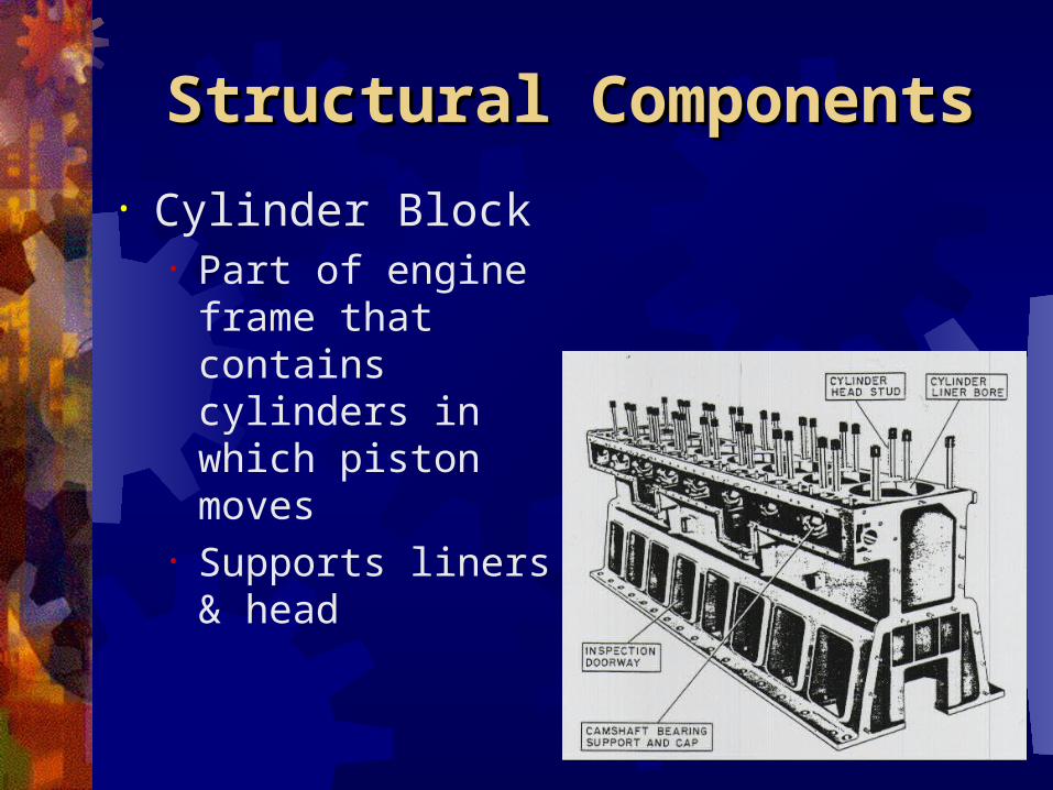
• Cylinder Block• Part of engine
frame that contains cylinders in which piston moves
• Supports liners & head
Structural ComponentsStructural Components
• Cylinder Head/Assembly• Serves to admit, confine, and release
fuel/air• Cover to cylinder block• Supports valve train
• Crankcase• Engine frame section that houses the
crankshaft• Oil sump
• Reservoir for collecting and holding lube oil
Moving ComponentsMoving Components
• Three Groups – according to motion• Reciprocating only (pistons and
valves)• Reciprocation & rotary (connecting
rods)• Rotary only (crankshafts and
camshafts)
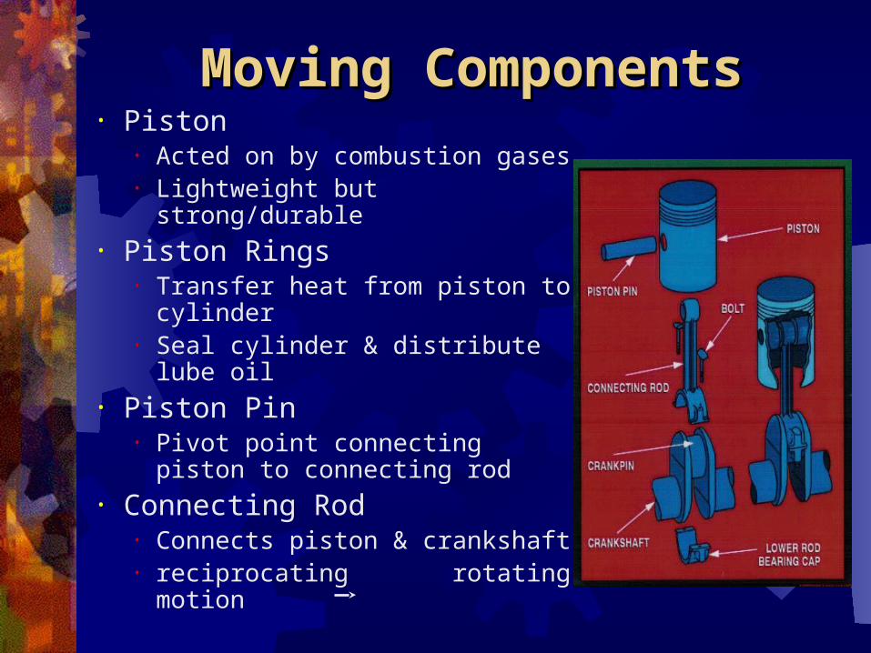
Moving ComponentsMoving Components• Piston
• Acted on by combustion gases• Lightweight but strong/durable
• Piston Rings• Transfer heat from piston to
cylinder• Seal cylinder & distribute lube
oil• Piston Pin
• Pivot point connecting piston to connecting rod
• Connecting Rod• Connects piston & crankshaft• reciprocating rotating
motion
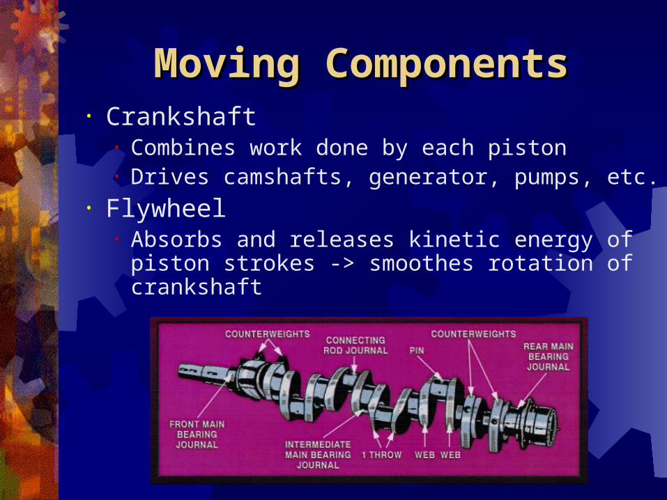
Moving ComponentsMoving Components• Crankshaft
• Combines work done by each piston• Drives camshafts, generator, pumps, etc.
• Flywheel• Absorbs and releases kinetic energy of
piston strokes -> smoothes rotation of crankshaft
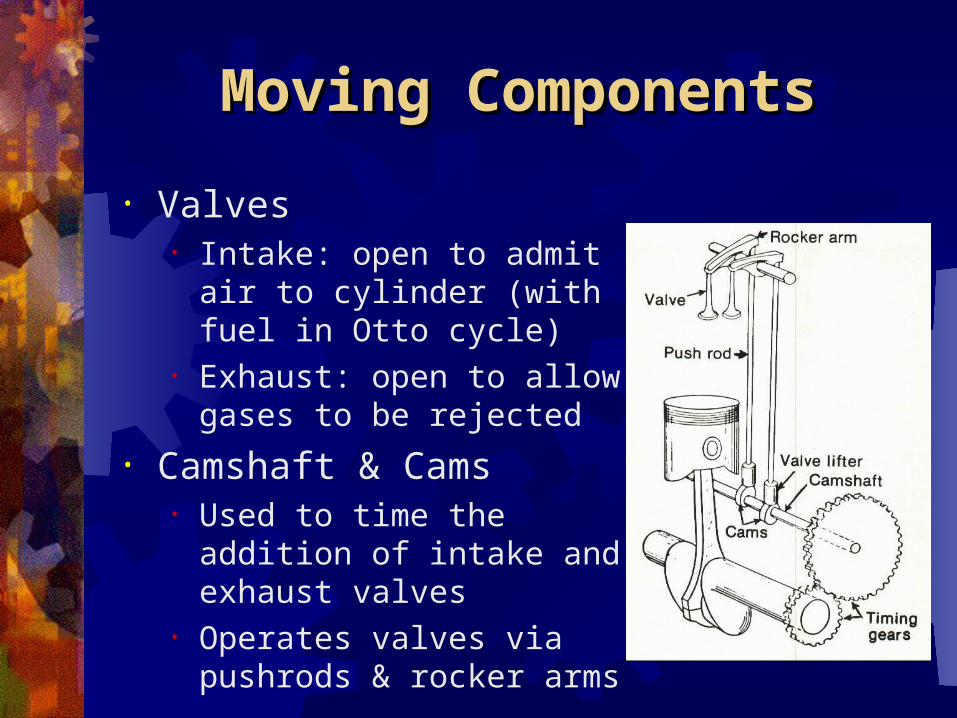
Moving ComponentsMoving Components
• Valves• Intake: open to admit air
to cylinder (with fuel in Otto cycle)
• Exhaust: open to allow gases to be rejected
• Camshaft & Cams• Used to time the addition
of intake and exhaust valves
• Operates valves via pushrods & rocker arms
OperationOperation
• Increased pressure of combustion gases acts on piston -> converted to rotary motion
• Can be 2 or 4 stroke engines• 2-stroke: 1 power stroke per 1
crankshaft rev• 4-stroke: 1 power stroke per 2
crankshaft rev
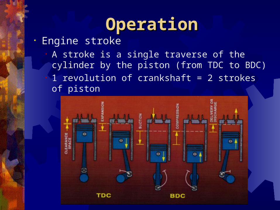
OperationOperation• Engine stroke
• A stroke is a single traverse of the cylinder by the piston (from TDC to BDC)
• 1 revolution of crankshaft = 2 strokes of piston
Four-Stroke Diesel Four-Stroke Diesel EngineEngine
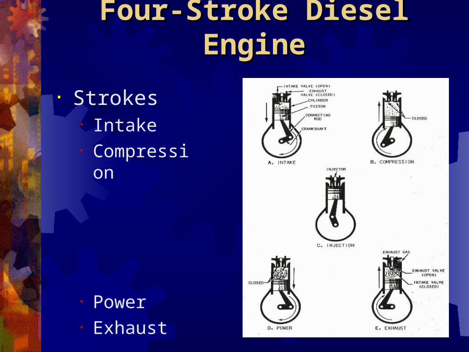
• Intake stroke• Intake valve open, exhaust valve shut• Piston travels from TDC to BDC• Air drawn in
• Compression stroke• Intake and exhaust valves shut• Piston travels from BDC to TDC• Temperature and pressure of air
increase
Four-Stroke Diesel Four-Stroke Diesel EngineEngine
• Power stroke• Intake and exhaust valves shut• Fuel injected into cylinder and ignites• Piston forced from TDC to BDC
• Exhaust stroke• Intake valve shut, exhaust valve open• Piston moves from BDC to TDC• Combustion gases expelled
Four-Stroke Diesel Four-Stroke Diesel EngineEngine
• Strokes• Intake• Compressi
on
• Power• Exhaust
Two-Stroke Diesel Two-Stroke Diesel EngineEngine
• 1 power stroke every crankshaft revolution (vice every two w/ 4-stroke)
• Uses pressurized air to simultaneously supply new air and expel combustion gases
• Scavenging• Exhaust valve open, inlet port exposed• Pressurized air enters, expels combustion
gases• Piston near BDC
Two-Stroke Diesel Two-Stroke Diesel EngineEngine
• Compression• Intake and exhaust valves shut• Piston travels from BDC to TDC• Temperature and pressure of air
increase• Power stroke
• Intake and exhaust valves shut• Fuel injected into cylinder and ignites• Piston forced from TDC to BDC
Two-Stroke Diesel Two-Stroke Diesel EngineEngine
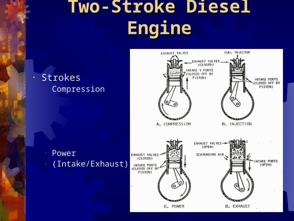
• Strokes• Compression
• Power• (Intake/Exhaust)
Two vs. Four-Stroke Two vs. Four-Stroke EnginesEngines
• Two-stroke advantages• Higher power to weight ratio• Less complicated valve train
• Four-stroke advantages• More efficient burning process• As size increases, power-to-weight
ratio improves
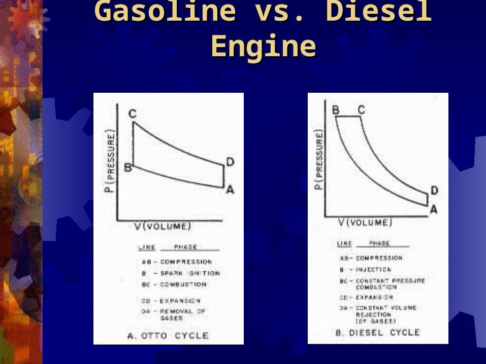
Gasoline vs. Diesel Gasoline vs. Diesel EngineEngine
Supporting SystemsSupporting Systems
• Air system• Supplies & removes air/gases• Air supplied at constant pressure by
blower/compressor• Fuel System
• Carburetor: mixes air & fuel in proper proportion (NOT on diesels)
• Fuel injector: sprays fuel in (more efficient)
Supporting SystemsSupporting Systems
• Ignition system• Diesel has compression ignition• Gasoline has spark plugs
• Cooling system• Uses fresh water and/or salt water to
cool• Lubrication system
• Provide lubrication and cooling• Drive Train – Direct or Indirect
Safety PrecautionsSafety Precautions
• Noise• Fuel Flammability• Maintenance• Water Issues

QuestionQuestions?s?