Embed Size (px)
Citation preview
Internal Charging Characterization: AE9 Model Framework and EMA3D-Internal
Nicole Pothier McGillivray, ScientistBryon Neufeld, Ph.D
Megan Maguire, Scientist5 September 2017
9/5/2017 1
Introduction
• Spacecraft charging is a well-known problem for space vehicles
• Previous evaluation techniques of spacecraft charging threats, particularly for internal charging, require drastic simplifications and assumptions regarding both the environment and the geometry
• We present a new approach for performing a thorough evaluation of spacecraft internal charging risks
9/5/2017 2
EMA3D-Internal
• EMA3D-Internal is a comprehensive tool for evaluation of internal spacecraft charging in a fully three dimensional and time dependent way– Spectrum Integration
– Geometry
– Monte Carlo Particle Transport
– Electrodynamic Electric Field Solution
– Computational Efficiency
9/5/2017 3
Spectrum Integration
• EMA3D-Internal is very flexible in terms of allowing the user to provide the electron spectrum based on actual mission ephemeris
• The environment interface was designed with AE9 in mind
• There is no limit to the number of time steps or energies in the spectrum (apart from computer memory limits)
9/5/2017 4
Spectrum Integration
• Modeling the radiation belt environment
– Tough to dohighly dynamic region; greatly expands and/or contracts depending on many factors
• AE9/AP9 is an environment framework that accurately accounts for space weather dynamics
– Provides models describing population of electrons and ions vs energy at varying confidence levels (75%, 95%, 99%, etc.)
9/5/2017 5
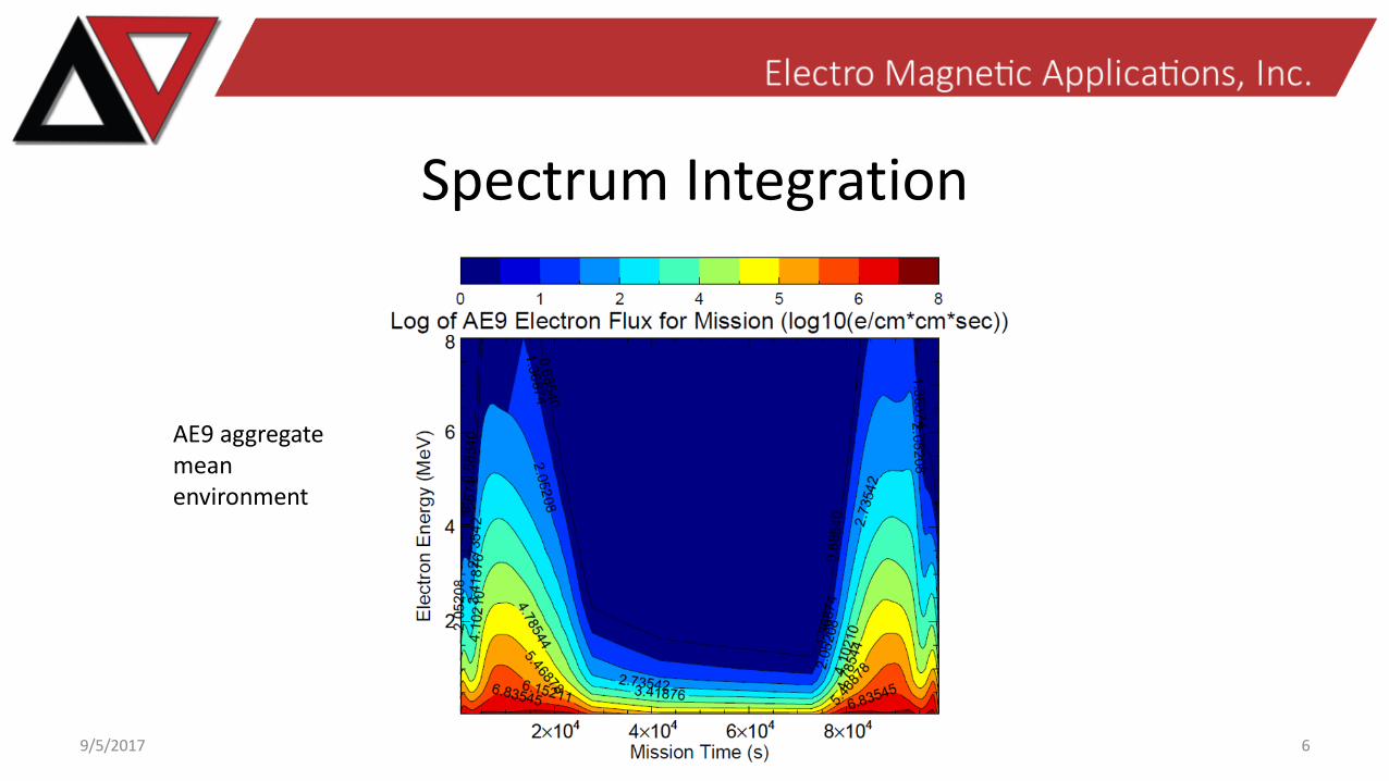
Spectrum Integration
9/5/2017 6
AE9 aggregate mean environment
AE9 Woes
• Data coverage– Very good coverage for electrons from LEO to GEO for 0 to 63 deg
inclinations• Some data exists for higher inclinations, but not with high fidelity
• For such missions, must use much more conservative environments (from data sources with higher fidelity) than ideal
– More coverage (and higher fidelity data) for polar orbits (LEO to GEO) would greatly improve AE9/AP9 statistics• But, publicly available data is very hard to come by!
9/5/2017 7
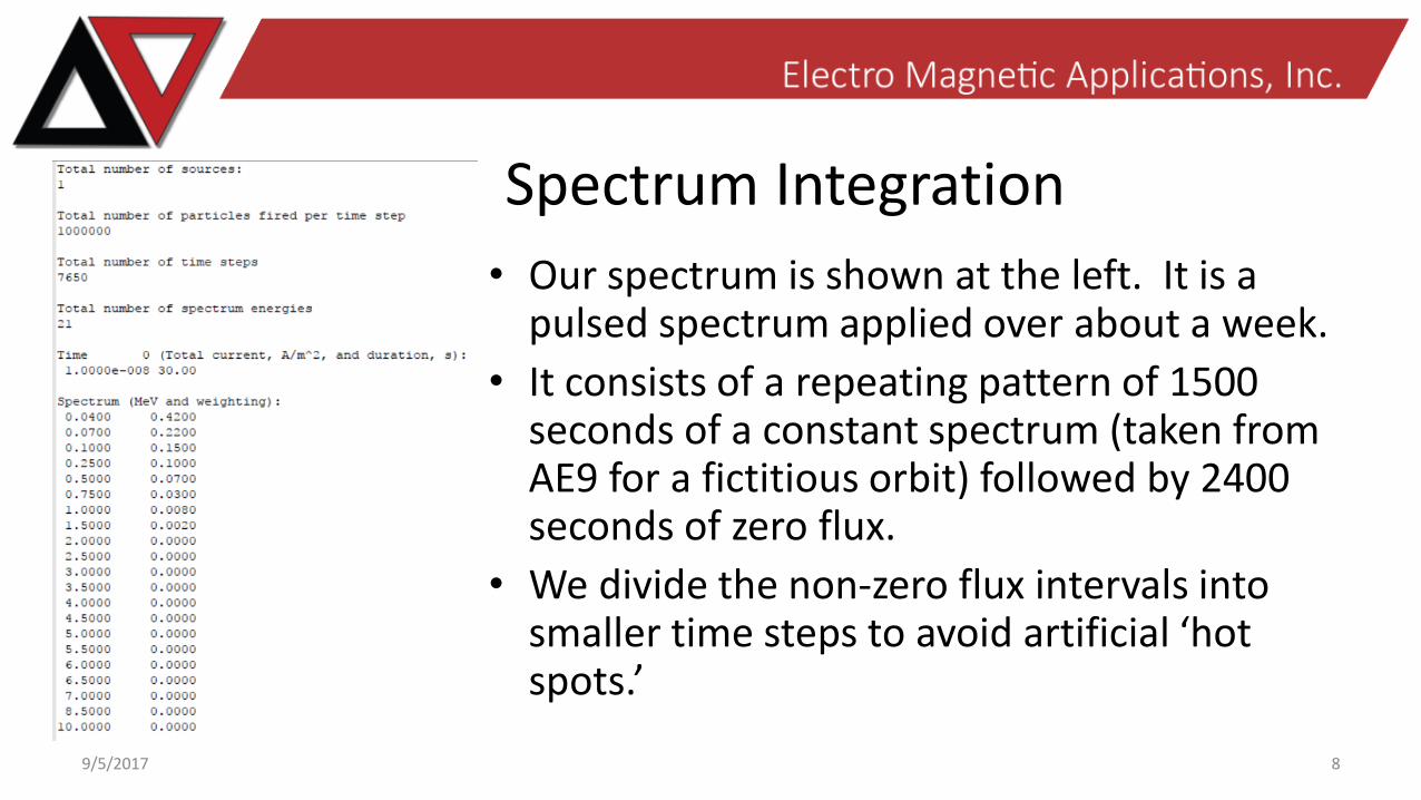
Spectrum Integration
• Our spectrum is shown at the left. It is a pulsed spectrum applied over about a week.
• It consists of a repeating pattern of 1500 seconds of a constant spectrum (taken from AE9 for a fictitious orbit) followed by 2400 seconds of zero flux.
• We divide the non-zero flux intervals into smaller time steps to avoid artificial ‘hot spots.’
9/5/2017 8
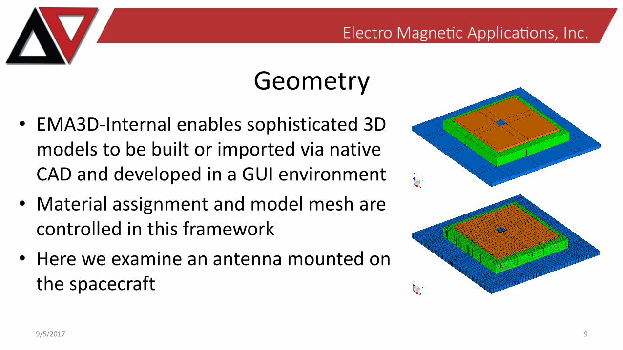
Geometry
• EMA3D-Internal enables sophisticated 3D models to be built or imported via native CAD and developed in a GUI environment
• Material assignment and model mesh are controlled in this framework
• Here we examine an antenna mounted on the spacecraft
9/5/2017 9
Geometry
• The dielectric materials are examined with the following properties:– DIEL1
• Sigma = 1e-10 S/m, RIC = 0
• Density = 2000 kg/m3
– DIEL2• Sigma = 1e-18 S/m, RIC = 0
• Density = 1800 kg/m3
• We run the simulation in a pulsed environment for about 7 days with a planar beam
9/5/2017 10
Metal Patch
Metal Ground
Upper DielectricDIEL2 Lower Dielectric
DIEL1
Monte Carlo Particle Transport
• The user provided spectrum (AE9) serves as the basis for the Monte Carlo particle transport analysis to obtain the source of charge and energy deposition due to electron irradiation
• EMA3D-Internal interfaces with GEANT4 to perform the Monte Carlo particle transport simulation
• Geometry mesh is converted into GDML format
• Spatiotemporal charge and energy deposition profiles are recorded through tracking and stepping utilities
9/5/2017 11
Electrodynamic Electric Field Solution
• The charge and energy deposition is the source for the electrodynamic field solution
• EMA3D-Internal uses a Finite Element approach to solve for the electrodynamic field (Elmer Multiphysics)
• The spatiotemporal charge and energy deposition profiles from the particle transport analysis are directly coupled into the electrodynamic evaluation
9/5/2017 12
Computational Efficiency
• EMA3D-Internal is set up to provide efficient numerical computation for complex problems
• The interface with Elmer Multiphysics implements a hash-table motivated data structure to quickly access the source for electric field generation
• The simulation is performed with parallel computing methods, enabling high powered computation for difficult problems
9/5/2017 13
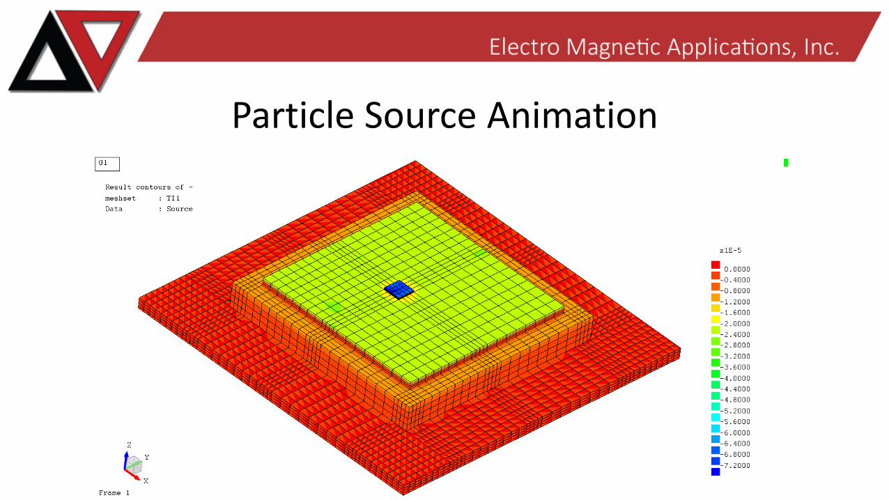
Particle Source Animation
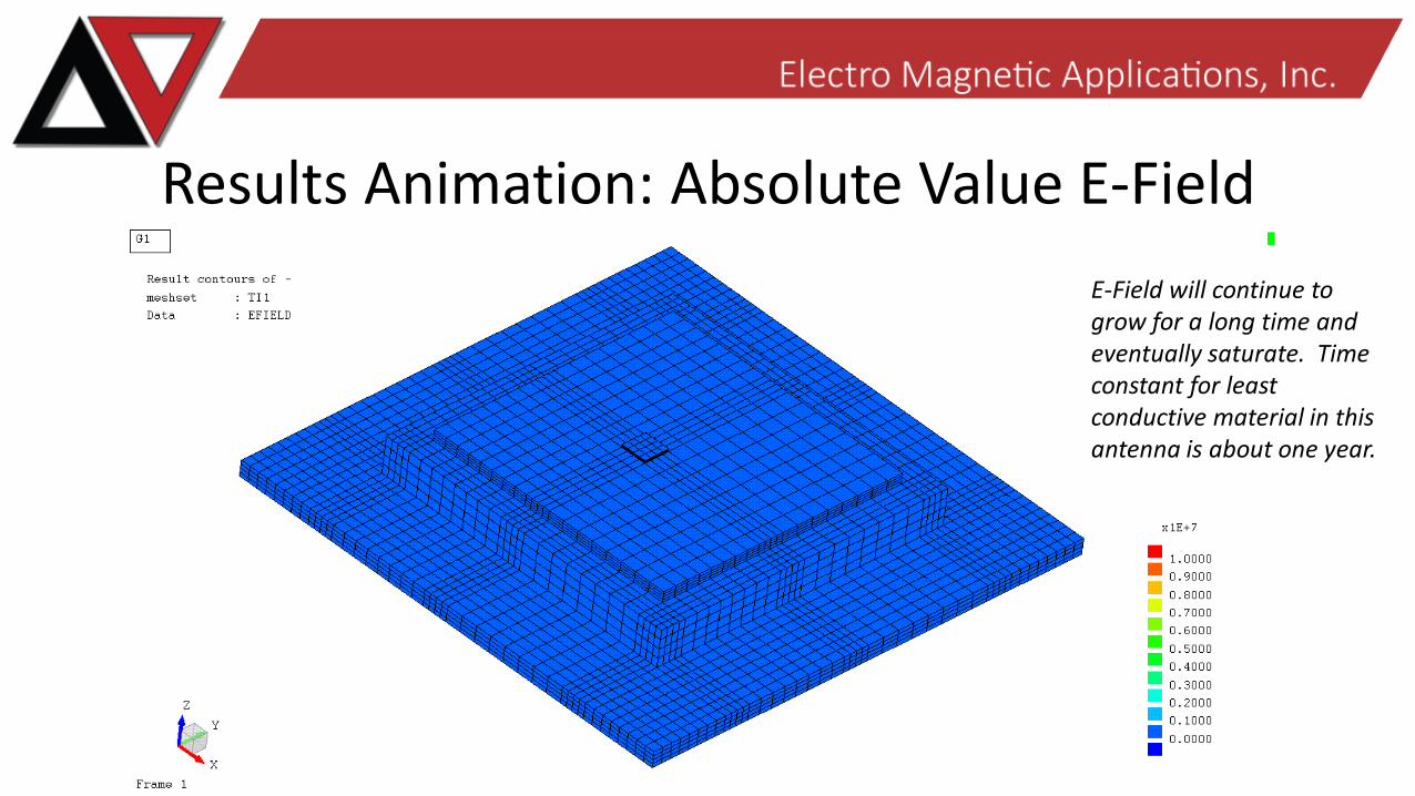
Results Animation: Absolute Value E-Field
E-Field will continue to grow for a long time and eventually saturate. Time constant for least conductive material in this antenna is about one year.
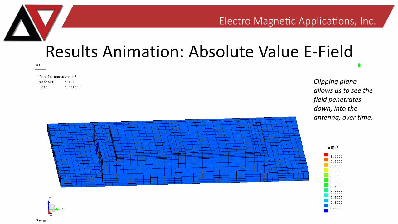
Results Animation: Absolute Value E-Field
Clipping plane allows us to see the field penetrates down, into the antenna, over time.
Conclusions• AE9 environment characterization is the preferred method for environment
input into EMA3D-Internal charging model– Limited data coverage for high inclination orbits requires more environment
conservatism in model than desired
• Combination of AE9 software and EMA3D-Internal present a highly relevant analysis to assist in the mitigation of internal spacecraft charging
• We have introduced the first commercial 3D internal charging software for use in the spacecraft charging community, and examined the susceptibility of a generic antenna in a space radiation environment using EMA3D-Internal
9/5/2017 17