Embed Size (px)
Citation preview
Ministry of Worksand Development
341.2
82IN
INTERMITTENT BIOLOGICAL
SAND FILTERS FOR
WASTEWATER TREATMENT
Civil Division Publication
CDP906/A: 1982
\ \
CONTENTS Page
SCOPE 1
DESCRIPTION OF THE PROCESS 1
2.1 Basic Layout and Method of Treatment 1
2.2 Effluent Characteristics 2
2.3 Process Applications 2
DESIGN CRITERIA 2
3.1 Siting 2
3.2 Loading Rates 4
3.3 Number of Beds 4
DESIGN DETAILS 5
4.1 The Beds 5
4.2 The Underdrains 5
4.3 The Structure 8
4.4 Dosing System 8
OPERATION AND MAINTENANCE 10
'-- 3MI.2. S2JM
SCOPE
This document is an update of the May 1974 publication entitled'Intermittent Sand Filters for Sewage Treatment'. It is intendedto provide guidelines for the design, installation and operationof intermittent biological sand filters for use as 'secondary' or'tertiary' units for the treatment of domestic wastewater.
The design guidelines given do not differ a great deal from thosecontained in the earlier publication, but minor modificationshave been made and more information given on matters of designdetail.
It is emphasised that the design information given relates onlyto intermittent biological sand filters operated as 'secondary1or 'tertiary' treatment units treating domestic wastewater. Itis not relevant either to rapid sand filters used for either thetreatment of water or wastewater, or to slow sand filters used inwater treatment.
2 DESCRIPTION OF THE PROCESS
2.1 Basic Layout and Method of Treatment
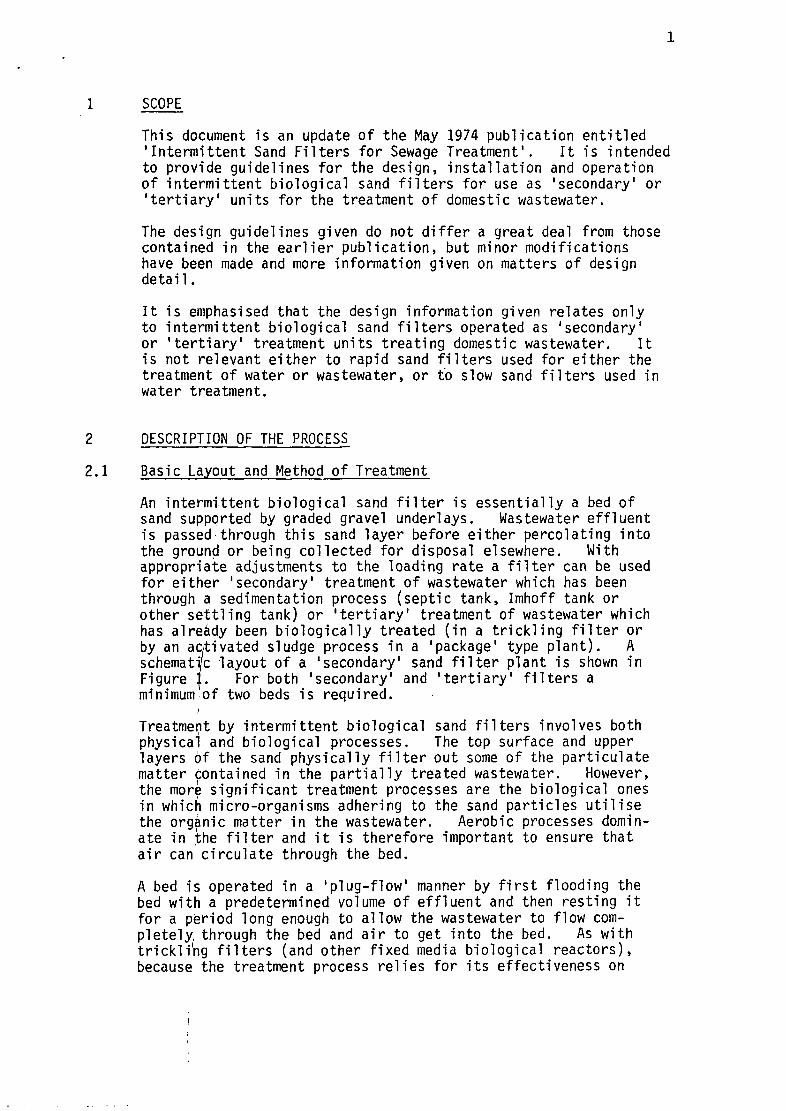
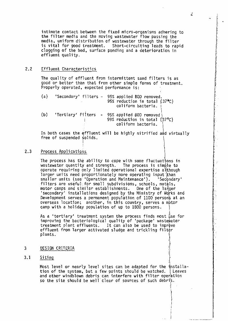
An intermittent biological sand filter is essentially a bed ofsand supported by graded gravel underlays. Wastewater effluentis passed through this sand layer before either percolating intothe ground or being collected for disposal elsewhere. Withappropriate adjustments to the loading rate a filter can be usedfor either 'secondary1 treatment of wastewater which has beenthrough a sedimentation process (septic tank, Imhoff tank orother settling tank) or 'tertiary' treatment of wastewater whichhas already been biologically treated (in a trickling filter orby an activated sludge process in a 'package' type plant). Aschematic layout of a 'secondary' sand filter plant is shown inFigure j. For both 'secondary' and 'tertiary1 filters aminimum of two beds is required.
iTreatment by intermittent biological sand filters involves bothphysical and biological processes. The top surface and upperlayers of the sand physically filter out some of the particulatematter contained in the partially treated wastewater. However,the more significant treatment processes are the biological onesin which micro-organisms adhering to the sand particles utilisethe organic matter in the wastewater. Aerobic processes domin-ate in the filter and it is therefore important to ensure thatair can circulate through the bed.
A bed is operated in a 'plug-flow' manner by first flooding thebed with a predetermined volume of effluent and then resting itfor a period long enough to allow the wastewater to flow com-pletely, through the bed and air to get into the bed. As withtrickling filters (and other fixed media biological reactors),because the treatment process relies for its effectiveness on
intimate contact between the fixed micro-organisms adhering tothe filter media and the moving wastewater flow passing themedia, uniform distribution of wastewater through the filteris vital for good treatment. Short-circuiting leads to rapidclogging of the bed, surface ponding and a deterioration ineffluent quality.
2.2 Effluent Characteristics
The quality of effluent from intermittent sand filters is asgood or better than that from other simple forms of treatment.Properly operated, expected performance is:
3
3.1
(a) 'Secondary' filters -
(b) 'Tertiary1 Filters -
95% applied BOD removed.95% reduction in total ;(379C)
coliform bacteria.
95%99%
applied BOD removed \reduction in total (!37°C)coliform bacteria.
In both cases the effluent will be highly nitrified and virtuallyfree of suspended solids. 1
2.3 Process Applications
The process has the ability to cope with some fluctuations inwastewater quantity and strength. The process is simple tooperate requiring only limited operational expertise althoughlarger units need proportionately more operating input '(thansmaller units (see 'Operation and Maintenance1). 'Secondary'filters are useful for small subdivisions, schools, motels,motor camps and similar establishments. One of the larger'secondary1 installations designed by the Ministry of Works andDevelopment serves a permanent population of 1100 persons at anoverseas location; another, in this country, serves a motorcamp with a holiday population of up to 1800 persons.
As a 'tertiary' treatment system the process finds most ,use forimproving the bacteriological quality of 'package1 wastewatertreatment plant effluents. It can also be used to improveeffluent from larger activated sludge and trickling filterplants.
DESIGN CRITERIA
Siting
Most level or nearly level sites can be adapted for thetion of the system, but a few points should be watched.
nstalla-Leaves
and other windblown debris can interfere with filter operationso the site should be well clear of sources of such debris.
DistributionBox
Septic Tank Dosing Tank(dosing is by eithersiphon or pump )
Intermittent Biological Sand Filters( Dosed on Rotation )
Figure 1: SCHEMATIC LAYOUT OF TREATMENT PLANT INCORPORATINGINTERMITTENT BIOLOGICAL SAND FILTERS AS 'SECONDARY' TREATMENT
Where the intention is that the treated effluent soak intothe subgrade, checks should be made to ensure that the sub-grade is suitable for such a system.
The filters are not visually intrusive, nor, if they areproperly designed, operated and maintained, do they giverise to odours. They can therefore be sited close topublic places, although a minimum clearance of 30 metresfrom dwellings is recommended for small plants. Agreater distance is advisable for larger plants.
To reduce vandalism and in the interest of public healthand safety the site should be fenced.
3.2 Loading Rates
'Secondary' filters should be designed for a total filterarea of between 7 and 10 square metres per cubic metre ofeffluent per day (at flows of 200 litres/person day, thisis equivalent to an area of between 1.4 and 2 squaremetres of bed/person).
Loading rates for 'tertiary' filters can be significantlyhigher due to the more stable nature and lower solids con-tent of the effluent. Total bed area should be between0.67 and 2 square metres per cubic metre of effluent perday, (0.133 and 0.4 square metres/person at 200 litres/person day).
These areas are for the total filter area of the system(e.g the total of both bed areas of a two bed plant).The choice of dosing rate within the ranges given abovedepends upon two main factors. Firstly, the dosingarrangement: if the beds are automatically dosed inrotation (secondary beds each dosed twice daily, tertiarybeds each dosed three or four times daily) the beds workmore efficiently and can be sized on the higher dosingrates. Where the beds are alternated weekly they shouldbe sized on the lower dosing rates. Secondly: wherefilters are put in at holiday resorts or other placeswhich have marked variation in seasonal load, filtersshould be sized for the high season load, but on thehigh bed loading rate.
3.3 Number of Beds
At least two beds must be provided and up to four may beused if topography or total bed area requires this. Allbeds at a given installation should be the same size toensure equal dose rates.
The maximum size of an individual bed is determined by the needto ensure that the bed receives an even dose over its entirearea. As a guide, the largest beds installed by the Ministryof Works and Development each cover an area of approximately630 square metres, although in this case the beds were rectangu-lar and fitted with twin dosing points.
4 DESIGN DETAILS
4.1 The Beds
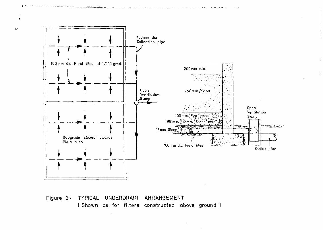
The beds are made up of four distinct layers of material (seefigure 2). The top 750 mm should consist of a fairly uniformmedium sand. Sand with particle sizes between 0.3 amd 0.6 mmand a uniformity coefficient of not greater than 4 has been usedsuccessfully. However, if this is not readily available aslightly coarser sand may be used although for 'secondary'filters it is important not to have the sand so coarse thatsolids in the applied wastewater will be washed deep into thebed. In general a uniform river sand with particle sizesgenerally in the 0.3 to 0.6 mm range will prove suitable.
The sand layer should rest on a 100 mm layer of 3.5 to 6.5 mmparticle size 'pea' gravel beneath which is an 150 mm layer of12 mm stone chip.
The underdrain system should be beneath this layer and beddedin 18 mm stone chip to a minimum cover depth of 40 mm.
Each layer should be levelled as accurately as is practicable.Particular care should be taken to ensure that the top surfaceof the bed is dead level as failure to do this leads to unevendosing. As the bed is designed to act as a filter, the bedmaterial must not be densely compacted. Mechanical compactionequipment should not be used, rather each layer should be light-ly compacted by hand.
4.2 The Underdrains
These serve both to provide for the collection of treatedeffluent and to keep the bed aerobic. It follows thereforethat an underdrain system should be provided even for thosebeds which are designed to have the treated effluent soak intothe subgrade.
The underdrain system should consist of a network of 100 mmfield tile drains at not greater than five metre centres.The drains should be laid on a grade of 1:100 or steeper andshould drain to a main collector pipeline (usually 150 diameterand of conventional pipe rather than field tiles). Thiscollector pipe may be either within the filter bed area oroutside it.
Jt ]"*
100mm dia. Field
i I
*
1
ttiles
|
t
*
tat 1/100 grad.
1
t
1 i *f
SubgradeField tiles
t
t
tslopes
i
t
ttowards
1
t
i
([
•
150mm dia.Collection pipe
OpenVentilation
,Sump
200mm min.
750mm/Sand
100 mm I Pea'gravel '??*.$$
150m m j/.12mm ;"Stone\chip"-v!;;
18mm
100mm dia Field tiles
OpenVentilationSump
Outlet pipe
Figure 2* TYPICAL UNDERDRAIN ARRANGEMENT( Shown as for filters constructed above ground )
-•--!*«
VentilationPipe
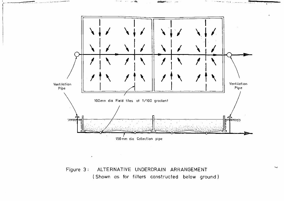
100mm dia Field tiles at 1/100 gradient
150mm dia Collection pipe
Figure 3: ALTERNATIVE UNDERDRAIN ARRANGEMENT( Shown as for filters constructed below ground)
The field tiles should be laid with 10 mm gaps between tiles and,to prevent stones getting into the drain, the top half circumfer-ence of the gap should be covered with a durable membrane(malthoid or similar). The subgrade should be evenly slopedtoward the field tiles. The use of perforated pipe type fielddrains is not recommended as the drain holes are too small andliable to be clogged by the build up of biological slimes.
The underdrain system must be vented to atmosphere to ensure agood airflow. Where filters are constructed above the surround-ing ground level, underdrain ventilation should be provided bymeans of an open sump on the collection pipe outside the filterbed (see figure 2). Where filters are constructed below, orpartly below, ground level, the collection pipe should beextended to each side of the bed and vertical upstand ventilatorpipes should be fitted to each end (see figure 3).
4.3 The Structure
Each filter bed should be confined by a vertical wall a minimumof 200 mm above both the top of the bed and the surroundingground. The wall should be of permanent materials. Reinforcedconcrete and concrete blocks on a concrete footing are commonlyused (see Figure 2).
Filters can be built on any reasonable natural subgrade. Thesubgrade should be graded in accordance with the requirementsof the underdrain system and, if it is intended that some or allof the effluent should soak away through a permeable subgrade,the surface of the subgrade should not be compacted but may belightly scarified.
4.4 Dosing System
The dosing chamber need be no more than a simple concrete tank.Its capacity should be equal to the quantity of effluent requiredfor one complete dose of one bed, (i.e sufficient to completelyflood the bed to a depth of 75 to 100 mm; see 'Operation andMaintenance1).
Dosing of the beds can be either by single or alternating dosingsiphon or by single or alternating pumps. With a single siphonor pump a simple distribution box or pipework valving can be usedto manually change the duty bed. For larger systems automaticrotation of beds is desirable and this can be achieved either byalternating dosing siphons designed such that each siphon's dis-charge primes the next siphon and each siphon controls the dis-charge to one of the beds, or by the use of alternating pumps withautomatic rotation of the duty pump. In either of the automaticcases provision must be made for manual switching to enable anyone of the filters to be taken out of operation for maintenancewithout affecting the operation of the others.
concrete splash pad
2 x D dia concretepipe
Influent pipe dia D
1m
Note -.tangential inlet of influent pipe to inlet well
75mm thickconcrete splash pad
IL
Sand
^ Peg gravel12mrn: stone .chip ..̂ t̂ l̂ -̂ -̂̂ r'18mm -stone chip. •>..•..:•. ;.-.•«.'.••, ;> ,•• .'*£:••. .,-...»•..
- pipe on end. as inlet well
from pump or dosing siphonmass __concreteplinth
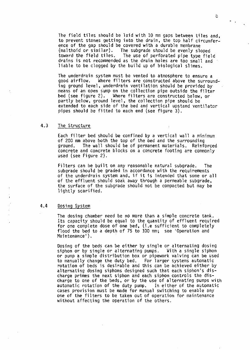
Figure 4: GENERAL ARRANGEMENT OF INLET TO BEDS
10
The Public Health Engineering section of the MWD has availableinformation on the design of single and multiple dosing siphons.
The preferred arrangement for dosing the bed is shown in Figure4, with the pipe coming in from below the top of the filter andtangentially fitted to a larger diameter upflow well. The up-flow well should be approximately twice the diameter of the in-coming pipe. This arrangement avoids effluent splash and theconsequent problems of odour and scouring of the filter surface.To further guard against splash and possible odour problems, thedischarge head should not be higher than necessary. Where ahigh head is unavoidable the depth of the upflow well should beincreased. Pipes which discharge downwards onto the filter bedare not recommended.
OPERATION AND MAINTENANCE
The preferred method of operation is to have each bed dosed inrotation, with beds sized such that filter beds used for'secondary' treatment are dosed twice daily under normal flowand 'tertiary' beds dosed three or four times daily. However,such a regime requires automatic alternating dosing arrangements.Where manual changeover of beds is used, the preferred method ofoperation is to change the duty bed weekly. Dosing of the bedsmust be by flooding them with a volume of effluent equivalent toa uniform depth of 75 or 100 mm over the bed area (75 mm for'secondary' beds, 100 mm for 'tertiary'). Continuous trickledosing is unacceptable as it prevents re-aeration of the bed.
A bed should be regarded as clogged when it takes longer than 30minutes for the applied effluent dose to soak away. Undernormal operation the beds should work for some months withoutclogging, although heavily loaded beds may need more frequentattention. When a bed does clog it should be left to thorough-ly dry out. It should then be swept with a yard broom toremove the surface mat of dry organic material and then rakedwith a rake with 25 mm tines. Under no circumstances shouldthe bed be dug over as this has the effect of pushing the organicmaterial, which is the cause of the clogging, more deeply intothe sand.
Beds should be kept free of weeds by hand weeding. Weedkillersmust not be used as the roots of the dead weeds remain in thefilter blocking it.
Over a period of time the top layer of sand may show signs ofbecoming clogged to the extent that normal sweeping and rakingbecomes ineffective. When this occurs the top 50-100 mm ofbed sand should be removed and replaced with fresh clean sand.Typically, this sand replacement will be necessary about onceevery five years.
11
Proper functioning of intermittent biological sand filters dependson the quality of the influent to the filter. It is thereforevery important that the upstream treatment plant and reticulationis well maintained and operated. Septic tanks must be desludgedas necessary. Also, care should be taken to minimise entry ofstormwater containing clay or similar material as this materialcan clog the filters.