Embed Size (px)
Citation preview

Interleaving IBOC Signals for aDigital HD Radio Multiplex
Philipp SchmidNautel Ltd
Hacketts Cove, NS, [email protected]
Abstract—With increased saturation of the VHF band II usedfor FM, few frequencies are available for new radio stations inmany markets. This paper describes the benefits of using the InBand On Channel (IBOC) signal in an all-digital configuration toboost the number of effective audio services in the FM band. Anew method of creating an all-digital IBOC signal configurationis described. Multiple instances of the dual sideband IBOCsignal are frequency shifted and added to create a multiplex ofindependent IBOC signals. This multiplex can then be broadcastusing a single wide-band IBOC capable broadcast transmitterand antenna system with or without an FM carrier. In orderto maintain a practical amplifier Peak-to-Average Power Ratio(PAPR) the multiplex must be processed by a modified PAPRreduction algorithm that factors in the frequency shift of theindividual IBOC signals. Among other combinations, it is possibleto combine 3 IBOC stations with an occupied bandwidth of 600kHz and receive up to 15 audio services on HD Radio receiversavailable today.
This paper proposes to retain VHF band II for its intendedpurpose of sound broadcasting and consider the possibilities ofan extended FM band including TV channel 5 and 6. A buildout of the FM band maintaining existing FM services, embracinghybrid FM plus IBOC stations and introducing all digital IBOCbroadcasts promises to provide a smooth digital radio transitionwith the end goal of improved spectral efficiency and lowertransmission costs.
Index Terms—FM, IBOC, HD Radio, spectral efficiency, spec-tral planning, OFDM, QPSK, PAPR, crest factor reduction,frequency reuse, HD Multiplex, advanced RF modulation
I. INTRODUCTION
There is much debate in the broadcast industry and regula-tory bodies on the future of the FM band II. It is clear thatglobally this limited resource is becoming increasingly sparseespecially in urban centers with many markets providing aneffective audio offering of no more than 25 to 30 FM stationson the typical radio dial. Listeners today demand a greaterdiversity of audio content as proliferated by today’s on-demandmultimedia culture. Also many national broadcasters wantto benefit from lower energy costs of digital radio. Thisleads many countries to consider alternatives to traditionalFM broadcasting, such as Digital Audio Broadcasting (DAB),Digital Video Broadcasting (DVB), and others in band IIIlocated between 174 MHz and 240 MHz. Norway is leadingthe way with official statements calling for the cessation ofnational FM broadcasting in 2017 [1], other countries, suchas Denmark [1] and the United Kingdom [2] are closely
monitoring digital listening and are prepared to make similarstatements once 50% of listening is on a digital platform.
HD Radio1 is a digital radio standard in use in the UnitedStates, Mexico, Canada, Panama, and the Philippines [3]providing an in band digital radio solution. In its presentdefinition, the digital signal is added on-channel on bothsides of the FM carrier. The signal is hence termed In BandOn Channel (IBOC). At present there are over 2000 stationsbroadcasting this signal with over 1700 added audio services inmulticast side-channels available only on HD Radio receivers[3] typically referenced as HD1 to HD5 on a receiver.
In this paper it is shown that the full potential of IBOCcannot be realized while operating in a hybrid FM+IBOCenvironment. A new all digital signal definition based onand compatible with the presently NRSC [4] defined IBOCstandard is proposed. The new signal frequency shifts and addsmultiple IBOC sidebands such as to make optimal spectrumuse creating what is termed a digital HD multiplex in thispaper.
Parallels can be drawn to the digital multiplex offered byDAB that shifts broadcasting from a single purpose transmis-sion to a shared use channel multiplex. DAB promises lowertransmission costs at 10x better energy efficiency comparedto broadcasting 15 individual FM stations [5] and coveragecan be matched to population centers using Single FrequencyNetworks (SFNs). This paper shows that these benefits canbe made available to IBOC, as well, offering cost savingsand added audio services. A single transmitter and antennasystem is used to transmit HD multiplex with 15 or moreaudio services.
Unlike DAB, the proposed concept uses today’s tri-modereceiver sets for all signal types: FM, FM+IBOC, and HDmultiplex. All of these signals may co-exist across the FMband. It is not expected that legacy FM receivers will beobsoleted for some time. Furthermore, band II is maintainedfor its original purpose of sound broadcasting, which it hasto maintain until FM is abandoned internationally and cross-border frequency allocations no longer have to be considered.
It has already been shown that matching IBOC coveragewith comparable FM coverage is possible using a hybridtransmitter at about 10% IBOC signal power compared to
1HD RadioTM is a proprietary trademark of iBiquity Digital Corporation.The author is not affiliated with and this text is not endorsed by iBiquity.

Fig. 1. IBOC spectral representation showing the location of logical channelsP1, P2, P3, and the Primary IBOC Data Service (PIDS) within the IBOCcarriers. P1’ contains additional forward error correction (FEC) for all digitalmodes. The FM carrier is only present in hybrid operation.
the FM [6]. HD multiplex is also expected to achieve FMcomparable coverage. While DAB requires less field strengthcompared to FM for good reception [7] [8], band III suffersfrom additional signal propagation losses. DAB often has toresort to fielding multiple SFN nodes to achieve comparablecoverage to the FM simulcast on DAB [8].
This poses the question: Can we supplement rather thanreplace band II with an all digital sound broadcasting solution?
The proposed HD Radio multiplex provides a practicalmethod of achieving an all digital transmission with improvedspectral efficiency and lower transmission costs. Much oftoday’s broadcast infrastructure can be maintained with thisapproach. It is based on the hybrid FM HD Radio standardthat can already be received on standard HD Radio receiversdeployed today. Leveraging this installed receiver base and thewide availability of commercial HD Radio receivers promisesto accelerate the digital transition period.
II. IBOC SIGNAL
HD RadioTM uses the IBOC signal specification [4] orig-inally developed by USA Digital Radio that later formediBiquity Digital Corporation. IBOC was initially introducedas a hybrid signal that maintains the traditional FM carrierwhile simulcasting the FM audio content on digital carriersand offering additional multicast audio and data services toHD Radio receivers only. This approach allows for a transitionperiod supporting legacy FM receivers until enough digitalradio receivers have been fielded to warrant all digital IBOCtransmission. Over 25 million HD Radio receivers are inuse today with many available receiver models and over 200automobile models offering HD Radio receivers [3].
The hybrid FM plus IBOC signal places two sidebands ofOrthogonal Frequency Division Multiplex (OFDM) carrierson either side of an FM carrier as shown in figure 1. Eachsideband is organized into a number of frequency partitionseach composed of 18 data bearing carriers and flanked byreference carriers on either side. The system can be config-ured for several possible service modes that enable differentcombinations of frequency partitions and Forward Error Cor-rection (FEC) robustness. In the basic MP1 service mode, 10frequency partitions are enabled per sideband for a total of 382carriers across both sidebands; note the additional referencecarrier on the outside of either sideband.
Service Type Data Rate (kbps) / TotalMode Relative Robustness kbps
P1 P2 P3MP1 hybrid 98.4 2 98.4MP3 hybrid 98.4 2 24.8 4 123.2MP11 hybrid 98.4 2 49.6 4 148.0MP5 digital 24.8 1 73.6 2 24.8 4 123.2MP6 digital 49.6 1 48.8 2 98.4
TABLE I: IBOC Service Mode Data Capacities [9]
The ratio between the total integrated power of all 382 IBOCcarriers to the single FM carrier is termed the IBOC injectionratio. Typically the injection is in the range of -20 dBc or 1%to -10 dBc or 10% of the FM carrier power. A detailed studyconducted by National Public Radio (NPR) labs [6] of 50example stations revealed that at an injection ratio of -10 dBcmobile reception of IBOC exceeds that of FM reception at117% of population served compared to good analog FMreception. Indoor and portable reception of IBOC is slightlyreduced at 83% and 81% of analog FM coverage respectively.This demonstrated the point that a band II digital solution canachieve FM coverage parity.
It is on the basis of these findings that this paper usesthe approximation that the coverage of an all digital IBOCtransmitter at 10% of analog FM power levels roughly equatesto FM coverage. This is an approximation as the coding gainand total power requirements of all digital service modes asdiscussed in section IV-B need to be factored in for a completeanalysis.
Advanced service modes, such as service mode MP3, enable2 additional frequency partitions in toward the FM carrier.When enabling up to 4 additional frequency partitions asper service mode MP11, the IBOC signal occupies a full100 kHz on either side of the FM carrier. This typicallyrequires reducing or carefully controlling FM modulation inorder to avoid the FM spectral content from bleeding intothe IBOC carriers. Table I provides an overview of commonservice modes and their associated data capacities.
The total capacity is broken into logical channels, referredto as P1, P2, and P3. Each logical channel has varying degreesof forward error correction associated with it designated witha relative robustness number, where 1 represents the highestrobustness. The coding gain for some of these service modesis discussed further in section IV-B. The total data capacityis a function of the total number of enabled quadrature phaseshift keyed (QPSK) modulated carriers less the amount usedby forward error correction.
A. Peak-to-Average-Power Ratio Reduction
The FM signal is a single continuous wave carrier systemwith a constant base band envelope. IBOC, on the otherhand, is the summation of a multitude of OFDM carriersthat together create an almost noise like base band envelope.Therefore, in order to maintain a reasonable PAPR suitablefor broadcast transmitters a PAPR reduction algorithm is used

[10]. The essence of this algorithm introduces noise within thefrequency domain IBOC constellation such as to cancel peaksin the time domain. This is possible since the Quadrature PhaseShift Keying (QPSK) nature of IBOC is insensitive to noiseand can tolerate a degree of distortion without affecting signalreception. The basic steps of this algorithm are
1) The signal is clipped in the time domain limiting theabsolute peak while maintaining the base band phase inthe IQ domain.
2) The time domain signal is converted into the frequencydomain using a Fast Fourier Transform (FFT) afterremoving the pulse shaping function.
3) Frequency bins outside of the signal bandwidth arereduced.
4) The in-band constellation points are cleaned to avoidexcessive noise.
5) The result is transferred into the time domain using aninverse FFT process.
6) These steps are repeated until a reasonable PAPR isachieved.
The gains of the time domain clipping are partially undonein the frequency domain correction steps. An iterative ap-proach eventually settles the PAPR from over 12 dB to around6-8 dB (see table II). In a hybrid signal configuration takingthe added FM carrier into account leads to significant saving inthe combined PAPR [10]. When creating an all digital signalconfiguration by interleaving IBOC signals this algorithm mustbe modified as described in section III.
B. All Digital Signal
There are two types of service modes: hybrid and all digitalservice modes as indicated in table I. Hybrid service modesexpect the FM carrier to be present and force an HD Radioreceiver to play the FM audio prior to blending to the digitalsimulcast. Digital service modes, on the other hand, mutethe HD Radio receiver initially to squelch the non-existentFM audio prior to producing the digital audio stream. Sinceall digital service modes have no analog fall back audio,digital service modes generally make a higher robustnesslogical channel available for the main audio transmission (seesection IV-B) and possible other audio streams.
The challenge with the all digital service modes MP5 andMP6 is that once the FM carrier is turned off 200 kHz of band-width are left unoccupied. The IBOC standard [4] provides adefinition of secondary service mode carriers (MS modes) thatfill in the 200 kHz of the FM carrier at a configurable powerlevel below the main outer carriers. This signal configurationpromises enhanced data capacity and more audio streams.While this signal configuration is of interest and can also beapplied to the interleaved IBOC signal configuration, at thetime of writing secondary service modes have not yet beenimplemented on the broadcast side and consequently receiversare lacking support for these modes as well. Hence there isno value proposition for turning off the FM carrier in favor ofsecondary service modes at this time.
Fig. 2. Spectrum of HD multiplex in MP3 mode captured from a single IBOCtransmitter broadcasting three stations A, B and C at 97.9 MHz, 98.0 MHzand 98.1 MHz. Each station may carry up to 5 audio services.
III. INTERLEAVING IBOC SIGNALS
The concept presented in this paper explores how we candefine an all digital IBOC signal standard that makes use ofthe existing base of IBOC receivers in common use today. Wecan fill the 200 kHz void left by the FM carrier with additionalsets of OFDM carriers that are independently modulated.By frequency shifting and interleaving these sets of IBOCcarriers we can create a multiplex of HD radio signals, latersimply termed HD multiplex, of varying occupied bandwidthsand payload capacities. The addition of these signals can bebroadcast from a single transmitter and antenna system makinguse of a larger and more efficient transmitter.
Figure 2 shows an example signal configuration of threesets of IBOC carriers marked as sets A, B and C. In thisexample, service mode MP3 was chosen, as it does not utilizethe entire 100 kHz of bandwidth alloted to each sidebandclearly outlining the IBOC sidebands. A similar configurationcan be created using service mode MP5, which then fills in theremaining frequency gaps in between sidebands. This providesthe signal with additional FEC as seen by the robustnessnumbers in table I. In this way the entire 600 kHz of occupiedbandwidth are used.
The receiver will tune only into the sidebands of interestand ignore the remaining sets of carriers. For example, if themultiplex is centered at 98.0 MHz, a receiver would tune intostation A at 97.9 MHz, station B at 98.0 MHz and station Cat 98.1 MHz. All HD Radio receivers on the market todayare capable of tuning into station A and C. Those receiversequipped with European tuning modes capable at dialing in100 kHz frequency steps will receive the full multiplex. Oncetuned to a station, the receiver can select the HD2 to HD5

sub channels. Please note that this is the most basic signalconfiguration further combinations are also possible as shownin figure 4.
The concept is based on the key observations in the follow-ing sections.
A. Frequency Shifted Peak Reduction
We cannot simply treat the carriers of a shifted station asadded to the original OFDM signal. IBOC symbols are cyclicin nature, while the frequency shift is a continuous wave.Note that the receiver does not see this shift as it directlytunes to the channel frequency. It only needs to be consideredwhen looking at a shifted station at the baseband In-phaseand Quadrature (IQ) signal and bringing the carriers backinto the frequency domain using the FFT this interaction withthe continuous frequency shift causes a phase shift from onesymbol to the next. To the standard PAPR reduction algorithm,this rotation appears incorrectly as noise to be corrected.Therefore, we must alter the standard algorithm to make itaware of which sets of carriers are shifted. First consider thedefinition of the nth IBOC symbol as defined by NRSC-5C[11]:
yn(t) = h(t− nTs)Cmax∑c=Cmin
X̄n[c]ej2π∆fc(t−nTs) (1)
where• n = 0, 1, 2, 3...,∞ and 0 ≤ t <∞• X̄n[k] is the per carrier complex constellation value
matrix defined here as corresponding to the carrier c.• h(t) is the pulse-shaping function as defined in section
13.2 of NRSC-5C [11].• Ts is the symbol duration of 2.9 ms and ∆f is the carrier
spacing of 363.4 HzIn equation 1, the (t − nTs) term effectively resets the
phase of each carrier from one symbol to the next as thecomplex carrier shift always starts at e0 = 1 at the beginningof each symbol. Let’s look at what happens when a continuousfrequency shift is added to equation 1. In order to be able touse a single FFT process for PAPR reduction, the shift mustbe a multiple, m, of ∆f such that the energy of each carrierfalls nicely into a single frequency bin. For a 100 kHz carriershift, m is chosen to be 275 resulting in an effective carriershift of 99.928 kHz. At a carrier frequency of 87.5 MHz thisresults in a 0.82 ppm frequency error that is well within the1 ppm specified limit [12]. Equation 2 applies this frequencyshift to equation 1:
yn(t) = ej2πm∆fth(t− nTs)Cmax∑c=Cmin
X̄n[c]ej2π∆fc(t−nTs)
(2)
yn(t) = h(t− nTs)Cmax∑c=Cmin
X̄n[c]ej2π∆f(m+c)(t− cnTsm+c ) (3)
Fig. 3. Modified PAPR reduction algorithm taking into account the symbol-to-symbol phase rotation in frequency shifted IBOC modulator outputs.
In equation 3 we can see that carrier c is now shifted by afrequency of (m + c). However, the (t− cnTs
m+c ) term now nolonger evaluates to zero at discrete symbol intervals Ts leavinga residual changing phase from symbol to symbol. Evaluatingequation 3 at t = nTs provides:
yn(t = nTs) = h(0)
Cmax∑c=Cmin
X̄n[c]ej2π∆fmnTs (4)
This means that each carrier receives an incremental phaseshift of (2π∆fmTs mod 2π) at the start of each symbolcompared to the previous symbol. We can safely apply themodulus operation, since multiple rotations leave the carrierconstellation at the same phase value. For a 100 kHz shiftat m = 275 and using exact representations for ∆f and Tsevaluates to:
2π1488375
4096275
135
128
4096
1488375mod 2π = 0.245rad = 14.1◦
(5)Recognizing this symbol-to-symbol phase shift, we can
modify the PAPR reduction algorithm described in section II-Aby adding one phase accumulator for each shifted IBOCstation that is incremented on each symbol. For each iterationof the PAPR reduction algorithm, the current value of thephase accumulator is applied prior to constellation correctionand re-applied thereafter as shown in figure 3.
The center column in figure 3 essentially represents thestandard PAPR reduction algorithm while the outer columns
are the new additions. The figure shows an example of 3interleaved IBOC stations, but other combinations are possible,as well. Each shifted station must maintain a complex shiftingfrequency based on m∆f and compute the associated phaseincrement as shown above. At the start of each symbol, thephase accumulator is incremented by this value and the sameaccumulator value is used across all iterations within this sym-bol. Once the signal is converted into the frequency domain,the frequency bins are rotated by the phase accumulator value.The output of the frequency domain corrections are againrotated by the inverse of the phase accumulator in order torestore the original constellation point. Note that the pulseshaping function is not affected by the frequency shift as it isa real multiplication of a cosine function.
Note that a receiver can make use of this phase shiftingprinciple in order to decode a number of simultaneous IBOCtransmission using a single baseband down conversion path.This would allow the receiver to aggregate the payloads ofmultiple IBOC stations. Note that the receiver only needs tohave a single symbol tracking loop, since all stations are insync with one another.
B. Additional OFDM Carriers
The addition of more OFDM carriers does not significantlyalter the effectiveness of the described PAPR reduction algo-rithm. In our lab we practically found no difference in thepower envelope between the basic service mode MP1 andservice mode MP6 with 40% more OFDM carriers. Table IIshows the Complementary Cumulative Distribution Function(CCDF) for MP1 and MP6 evaluated at probabilities of 10-3
to 10-6. The signal is above the stated PAPR for the givenprobabilities which show little variation between MP1 andMP6 confirming this observation. For both cases the sameimplementation of the PAPR reduction algorithm have beenused. To demonstrate that it is possible to achieve a similarPAPR, an example signal composed of 3 interleaved MP5signals similar to the configuration shown in figure 2 witha total of 1512 carriers. However, these numbers were takenwith a better implementation of the PAPR reduction algorithmyielding better results and cannot be compared directly. It doesshow that PAPRs better than single MP5/6 are possible.
PAPR (dB)Probability Carriers 10-3 10-4 10-5 10-6
MP1 382 6.36 6.79 6.98 7.14MP6 508 6.35 6.75 6.99 7.04MP5 Multiplex 1512 5.40 5.52 5.58 5.62Shifted MP5 1512 10.1 10.7 11.0 11.2
TABLE II: CCDF Probabilities
For comparison purposes, table II also includes a columnfor shifted MP5 not using the described method simply addingshifted signals. Since the Root Mean Squared (RMS) powersof the signals add for the average power and peaks are dueto the addition in voltage, the overall PAPR increases to11.7 dB given the MP6 PAPR. A transmitter not using the
described method can expect to produce only 40% TransmitterPower Output (TPO) of a transmitter using this method. Acomparable PAPR to a single IBOC signal is only obtainedusing the method described in section III-A.
C. Signal Orthogonality
The key concept that allows OFDM systems to pack amultitude of independent carriers into a minimum of occupiedsignal bandwidth is that all carriers are on orthogonal basisfunctions that satisfy the property shown in equation 6 [13].∫ T
0
ψ∗i (t)ψk(t)dt = Kiδik (6)
where one function must be complex conjugated and the deltaoperator is defined as
δik =
{1 for i = k
0 otherwise(7)
The receiver can project the signal onto the orthogonalbasis and effectively reject the frequency contribution ofneighboring carriers and can be packed tightly together.
In order for HD Multiplex to pack individual stations closelytogether this property must be satisfied across the output ofmultiple independent IBOC modulators that are then frequencyshifted by m frequency bins. To demonstrate this property asingle carrier, i, from equation 1 and a shifted carrier, k, fromequation 3 are inserted into equation 6. Note that this analysisis done after the pulse shaping function h(t− nTs) has beenaccounted for and the guard interval has been collapsed backon to the front of each symbol. Removing the guard intervalresults in a shortened symbol duration of 128
135Ts.
∫ nTs+ 128135Ts
nTs
X̄n[i]e−j2π∆fi(t−nTs)
∗ X̄n[k]ej2π∆f(m+k)(t− knTsm+k )dt
(8)
Evaluating the integral:
=X̄n[i]X̄n[k]ej2π∆fn(1−k)Ts
j2π∆f(m+ k − i)ej2π∆f(m+k−i)t
∣∣∣nTs+ 128135Ts
nTs
(9a)
=Ki
j2π∆f(m+ k − i)(ej2π∆f(m+k−i) 128
135Ts) − 1) (9b)
Substituting exact values [11]:
4096Ki
1488375
ej2π1488375
4096 (m+k−i) 40961488375 − 1
j2π(m+ k − i)4096Ki
1488375
ej2π(m+k−i) − 1
j2π(m+ k − i)
(10)
We can see from equation 10 that for any integer valueof m + k − i the expressions evaluates to zero satisfying thecondition for i 6= (m+k). To see if the i = m+k case is also

satisfied, we use Euler’s formula to expand the numerator asshown in equation 11. For i = m+ k and m, i, k ∈ Z:
K̄icos(2π(m+ k − i))− 1 + jsin(2π(m+ k − i))
j2π(m+ k − i)
=K̄ijsin(2π(m+ k − i))j2π(m+ k − i)
=K̄isinc(2(m+ k − i)) = K̄i
(11)
Since the sinc(0) function assumes the value of 1, we haveshown that that any arbitrary carrier i of an unshifted IBOCsignal is orthogonal in all cases to any arbitrary carrier k thatis shifted by an arbitrary frequency shift m provided m is aninteger. Any reference to the symbol number is absorbed inthe constant K̄i, which indicates that this property is true forall symbols not just the first. Maintaining orthogonality meansshifted IBOC sidebands can be placed side-by-side with otherIBOC sidebands originated from another modulator with anyarbitrary shift provided the modulators are synchronized toprovide symbols at the same time. This is shown in figure 3by indicating that these modulators are synced to one another.
D. Interleaving IBOC Signals
The interleaving pattern shown in figure 2 is the mostbasic configuration. With an occupied bandwidth of 600 kHz,the resultant signal fits nicely into the lowest possible IBOCmodulator sample rate. This base rate is derived from thehighest carrier number in a single IBOC signal being 546requiring at least 1092 frequency bins in the modulator. Alength of 2048 is the next convenient 2n FFT length andtranslates into 2048 samples in the time domain. A guardinterval of 112 samples (α = 7
128 ) is added to these for atotal of 2160 samples in a symbol. Leading to a base samplerate of fs = 2160
Ts= 744187.5 Hz.
We are effectively utilizing only 508 carriers out of apossible 2048 in this configuration. Adding two IBOC signalsshifted by m = 275 and m = −275 now utilizes carriersfrom -821 to +821 which still fits into our 2048 point FFTlength. This means that the base sample rate can carry theHD multiplex and there is little computational impact to thePAPR reduction algorithm since FFT lengths are maintained.
Figure 4a shows the basic interleaving pattern with 600 kHzof occupied bandwidth that is also shown in figure 2. Pleasenote that the levels of the individual sidebands are somewhatarbitrary and have been chosen in this example such as to helptaper off the sideband shoulders due to possible transmitternon-linearity. To improve clarity, sidebands corresponding tothe same station are marked in the same color and by the sameletter code. A right pointing arrow indicates a lower sidebandand a left pointing arrow indicates an upper sideband. Thecorresponding tuning frequency for the receiver is indicatedin the box below the frequency axis.
It is possible to run the described PAPR reduction algorithmat multiples of the base sample rate. This makes it possible tofurther extend the interleaving patterns with more sidebands.The easiest extension may be to simply duplicate the 600 kHzmode for a 1.2 MHz solution at an FFT length of 4096
points at 1488375 Hz. It may be desirable to spread theavailable tuning frequencies evenly as depicted in figure 4b.In this example sidebands B and G are optional single side-band configurations without a corresponding sideband partnerthat may be enabled in the future. With 5 IBOC stationsalready, turning off these sidebands for now has acceptableimpact to the spectral efficiency of the overall system. Itis conceivable to build wider signal combinations increasingtransmitter linearity requirements over a wider bandwidth.It may be necessary to employ channel filters in order tomaintain spectral compliance and reduce spectral re-growthat the shoulders. Advanced AM-AM correction and memoryeffect compensation are a must for these signal types.
E. Single Sideband Modes
When turning off a sideband, the robustness of the singlesidebands B and G in 4b is significantly compromised. AtIBOC convolution code rates of 2/5 [11] turning off onesideband effectively punctures the overall code rate to 4/5leaving little FEC. A clean signal is required for good re-ception, therefore, figure 4 shows the single sidebands B andG at elevated power levels and the most robust IBOC servicemodes (MP5 and MP6) are recommended for this application.Compared to the other sidebands, single sidebands B and Grequire 3 dB more gain to compensate for the loss of the othersideband plus possibly another 6-8 dB to overcome losses incoding gain and frequency diversity. Finding the required gaincould be an interesting extension of this work.
Single sideband reception has already been demonstratedon existing receivers. HD Radio receivers with improvedsingle sideband reception modes will also benefit from greatersensitivity in standard hybrid signal cases, where one sidebandis impaired by a 1st adjacent interferer. Provided receiversaccount for the loss of a single sideband in symbol tracking,existing service mode definitions already present in receiverstoday could perform reasonably well in the field. Specificservice modes tailored for single sideband transmission maypresent further improvements and are under consideration forthis concept. However, new service modes require receiverupdates to the installed receiver base.
With single sideband configurations, it is also possible tocreate various narrow band modes, such as a 400 kHz modeby turning off the outermost sets of carriers from the basic600 kHz configuration. The 400 kHz mode in figure 4c alsodemonstrates that we can switch sidebands A and C and returnto 200 kHz tuning steps and no longer require European tuningmodes in the receiver. The 400 kHz mode also fits nicely intoexisting channel allocations.
Turning off sidebands B in figure 4c leads to a 200 kHzsolution as sown in 4d. In this case it makes sense to switchthe single sidebands again in order to condense the dialingpositions. The proposed method is highly flexible in occupiedbandwidth particularly when utilizing single sideband modesallowing it to be integrated into existing FM channel alloca-tions with minimal frequency repacking.

Fig. 4. Example interleaved IBOC signals for 200 kHz, 400 kHz, 600 kHz and 1.2 MHz bandwidth. Stations are indicated by color and letter code. Lowerand upper sidebands are indicated via arrows and the corresponding radio tuning frequency is shown.
F. Receiver Considerations
The big benefit of the proposed method is that it buildsupon existing HD Radio receiver products available today andreceivers already in the field. Since this is a new signal config-uration not specifically tested in today’s receiver products, weneed to look at signal compatibility with existing HD Radioreceivers.
The HD Radio receiver picks out only the sidebands ofinterest within the multiplex and rejects all others. The receiverwill ignore the carriers located in the FM space and once itdetects the presence of an all digital service mode mutes thenon existent FM audio transmission. The FM signal possess amore constant power envelope even taking frequency selectivefading into account compared to IBOC. Therefore, HD Radioreceiver manufacturers are advised to implement conservativeAutomated Gain Control (AGC) loops leaving headroom toaccount for signal peaks in the intermediate IBOC carriers inorder to avoid signal clipping. IBOC receivers must be able toreject up to 20 dB (100x) the FM power for standard hybridservice modes today. This means that IBOC receivers mustbe built with sufficient resolution in the front end and downconversion to decode a low level IBOC signal already. As apreliminary guideline the author recommends to not exceedmore than 10 dB signal power for any inner IBOC carriercombination until more receivers are tested with this newsignal configuration.
No matter how wide the broadcast signal’s occupied band-width configuration, the IBOC receiver will only select the
400 kHz of signal bandwidth required for the selected audiochannel. Compared to DAB or DVB with wider occupiedbandwidths, this should lead to lower cost HD Radio receiverimplementations. HD Radio receivers today are already builtto handle high 2nd adjacent channel D/U ratios outside the400 kHz desired bandwidth. In the field, very low secondajacent hybrid IBOC D/U ratios are common, so elevatedcarriers, such as subcarriers B and G in figure 4b shouldhave little impact on the reception of stations C and F in the1.2 MHz multiplex.
All HD Radio receivers are designed to work with thestandard hybrid signal modes and the all digital servicemodes MP5 and MP6. Yet, some receiver implementationsstill exhibit a dependence on the FM carrier for scanningstations. These types of receivers are required to be tunedmanually. Even with HD scan capability many receivers onlystop on the first IBOC station they encounter and the remainingstations still need to be tuned manually. The author questionsthe consumer experience of station scanning as we expandthe total number audio offerings. Perhaps an application levelelectronic program guide and station reference presents abetter alternative to new station discovery.
IV. IMPROVED SPECTRAL EFFICIENCY
The following sub-sections detail the chief factors thatcontribute to the improved spectral efficiency of all digitalIBOC transmission compared to FM: better audio capacityper kilohertz of occupied bandwidth, better protection ratios

Fig. 5. Listener evaluation of HD Codec audio performance [14] over variousbit rates. A mean opinion score of 5 represents the best perceived audio qualityand 1 the worst.
between desired and undesired IBOC transmissions, and betterfrequency packing through multiplexing a number of IBOCsignals that ensure consistent adjacent channel ratios andmaintain carrier orthogonality between adjacent stations.
A. Audio Capacity
Comparing IBOC audio service with FM audio service ishighly subjective due to the difference of audio impairment.FM audio with limited 15 kHz audio bandwidth can be madeto sound good using today’s audio processing technology.Often dynamic audio range is compromised in order to getthe loudest sounding station on the dial. FM also suffers fromsignal propagation related distortion that generally increasewith a drop in signal strength and under multi-path conditions.It is difficult to say what the average FM audio impairments tothe average listener are, but it is clear that much of the listeningis done beyond the protected contours at field strengths as lowas 42dBµV/m [8].
The dynamic range of HD Radio audio is superior sinceits loudness can be controlled via digital scale factors thatare broadcast over the air not requiring aggressive audioprocessing. HD Radio audio also does not degrade with signalquality until close to signal breakdown and intermittent biterrors are mitigated via error concealment often with littleimpact to the underlying audio. Since the HDC codec usedin HD Radio is a perceptual codec, lower audio bit rateswill preserve less of the original audio content. Looking atthe data capacities in table I, we want to formulate roughguidelines comparing audio capacity between FM and HDRadio. Fortunately, listening research was conducted by Dr.Ellyn Sheffield evaluating the effectiveness of the HD codecat varying bit rates [14]. In this report Sheffield states thatmost respondents in the survey could no longer discern theaudio quality difference of audio clips encoded above 48 kbps.Figure 5 reproduces the mean opinion scores she found forclassical music, jazz music, rock music and speech. A meanopinion score of 5 is the best score and a score of 1 isthe lowest or worst sounding audio. These scores should beviewed with respect to the unimpaired CD reference material.Classical and jazz show little degradation down to bit ratesas low as 36 kbps. Rock is starting to show some noticeable,
but likely tolerable, impairment at 36 kbps. Speech is the mostlikely content to produce noticeable impairment and the reportbreaks this category down to male and female speech sampleswith a somewhat greater degradation in female speech.
These test have been conducted with the HDC codec at fullstereo. Fortunately, there are two other audio modes that canbe employed at low bit rates: mono and parametric stereo.Speech impairment can be minimized by choosing a monobroadcast mode, since most spoken content has little stereoseparation. The author asserts that with mono transmissionsthe total bit energy can be dedicated to a single channeleffectively doubling these results. For example, a 24 kbpsmono transmission effectively turns into 48 kHz quality wherespeech still shows little impairment. Parametric stereo downmixes the stereo source material to mono, but maintainsside information for spatial intensity stereo generation andambiance regeneration at the decoder. Typically the sideinformation is coded in an additional 2-3 kbps channel [15].The author assert that we should be able to expect at least50% improvement in bandwidth utilization compared to fullstereo. This turns 24 kbps audio into 36 kbps or better audio.
MP5 MP6channel / mode channel / mode
rate (kbps) rate (kbps)HD-1 P1-24 parametric P1-24 parametricHD-2 P2-32 stereo P1-24 parametricHD-3 P2-24 parametric P2-32 stereoHD-4 P2-17 mono P2-16 monoHD-5 P3-24 parametric
TABLE III: Example Audio Allocations
Table III shows exemplary audio allocations for the alldigital service modes MP5 and MP6 that maximize the numberof audio offerings and is to be taken as an upper limit forthe number of possible audio offerings. Given the increasedaudio capacity described in this paper, it is likely that thevalue proposition favors higher audio quality and most stationwill operate with 3 or 4 audio streams and additional dataservices. Since the combined 200 kHz of IBOC bandwidthequals that allocated to FM, the spectral efficiency of IBOCis roughly 4-5 times that of FM. This increase in spectralefficiency is already leveraged in hybrid IBOC broadcastingtoday with around 1700 multicast stations available in the UStoday [3].
B. All Digital Protection Ratios
Today’s FM allocations typically require a 20 dB protectionratio at a station’s protected contour [16] and for higher fidelityFM audio even better ratios are desired. This limits the abilityof frequency reuse within the FM band. For hybrid operatingmodes, the co-channel D/U ratios are already well understood.Kean [16] has already shown that IBOC only requires a 4 dBco-channel D/U ratio under steady signal conditions regardlessof received signal strength. When subject to a Trimmed UrbanFast Rayleigh fading profile (60 km/hr) it was found that an

Fig. 6. Bit error rates for MP3 vs. MP3 and MP6 vs MP6 interference forsteady signal conditions. The highest robustness channel P1 of MP6 provides2.5 dB coding gain over MP6 P2.
additional 3 dB margin was required for solid IBOC reception.Under Raleigh fading conditions, up to 8 dB additional marginis required as the received signal strength dropped to -60 dBm.In hybrid co-channel interference, the desired IBOC sidebanddirectly interferes with the undesired IBOC sideband so it isnot unlike all digital interference.
For hybrid service modes, the analog FM presents a fallback option once the digital signal breaks down. Becauseof the time and frequency diversity between the IBOC car-riers and the FM carrier, there exists a likelihood that atdigital signal breakdown, the FM carrier is still present andcontributes positively to the overall availability of the mainaudio. Referring to table I we recognize that the all digitalservice modes MP5 and MP6 have channels with the highestrobustness level 1 in order to compensate for the loss of theFM fallback. MP5 and MP6 add parallel transmission of theP1 logical channel with 1/2 rate coding that is shifted in timeto add more time diversity as shown in figure 7. This createsa fall-back channel similar to the FM in hybrid transmission.
Fig. 7. Top: MP3 with analog fall back, bottom: MP5/MP6 Dual coded P1channel [11]
Fig. 8. Short spaced co-channel interference zones - top: 20 dB D/U Ratioused for FM provides 31.6% coverage, bottom: mobile MP6 at 4.5 dB D/U(orange) and steady signal reception at 1.5 dB (red) provides 83.2% to 93.6%coverage
Since the gains of this additional coding is not well under-stood, our lab conducted coded bit error tests on audio streamsplaced on the MP6 P1 and P2 partitions with robustness level 1and 2 respectively. The output of two IBOC transmitters werecoupled in a 3 dB splitter and the combined output was fed intoan iBiquity IBOC test receiver capable of displaying coded biterror rates on all logical channels. The two IBOC modulatorswere configured to produce a deterministic bit pattern forthe receiver to compute the bit error rate on. Relative powerlevels were measured using the integrated power readings of aspectrum analyzer. For the purposes of this test only a singleset of sidebands was tested with both transmitters configuredfor either MP6 or MP3 without an FM carrier.
For comparison to Kean [16] MP3 was tested on its P1and P3 partitions with robustness levels 2 and 4 respectively(please refer to table I for robustness levels). The results areplotted in figure 6. The MP3 P1 results shows few bit errors
above 4 dB D/U even the few remaining bit errors can beconcealed in the underlying audio and are barely noticeable.Listening is possible well below the 4 dB level with increasedfrequency of concealed errors and short dropouts. At the 3 dBlevel audio is impaired about every 10 s and at 2.5 dB thereceiver has trouble acquiring and keeping the channel. TheP3 channel behaves much the same, but requires an additional1.5 dB of D/U. This in part explains why audio placed todayon P3 carriers does not carry as far as the main audio.
The MP6 P2 partition is also marked as robustness level 2with a 2/5 convolution encoder, just like the MP3 P1 partition.The results in figure 6 confirm that both logical channels havethe same performance as expected. The interesting aspect isthe MP6 P1 channel with the highest robustness mode. Theadditional time diverse data stream does in fact provide codinggains up of to 2.5 dB. MP6 P1 can operate very well into a1.5 dB D/U without impairment. The receiver can acquire thesignal with as little as 0.5 dB D/U albeit it takes longer tolock. Once the receiver has locked and is producing audio, wehave been able to increase the undesired transmitter to up to5% above the desired power level. The receiver maintainedlock and produced impaired audio.
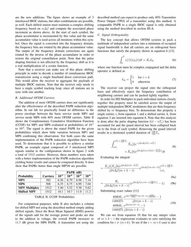
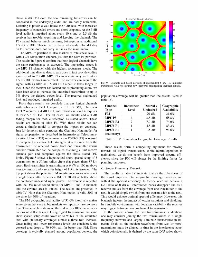
From these results, we conclude that any logical channelswith robustness level 1 require a 1.5 dB D/U, robustnesslevel 2 requires a 4 dB D/U, and robustness level 4 requiresat least 5.5 dB D/U. For all cases, we should add a 3 dBfading margin for mobile reception as stated above. Theseresults are stated in table IV. With these results we cancreate a simple model to compare the impact on coverage.Just for demonstration purposes, the Okumura-Hata model forsignal propagation as described in International Telecommu-nication Union (ITU) recommendation P.529-3 [17] was usedto compute the electric field strengths at a distance from thetransmitter. The received power from one transmitter versusanother transmitter can be computed assuming a unit receiveantenna gain and compared against the above stated D/Ulimits. Figure 8 shows a hypothetical short spaced setup of 3transmitters on a 50 km radius circle that places them 87 kmapart. Each transmitter is transmitting at 6 kW at 100 m aboveaverage terrain and a receiver height of 1.5 m is assumed. Thetop plot shows the potential FM interference zones where nota single transmitter exceeds a D/U of 20 dB or better abovethe combined undesired signal power. The exercise is repeatedwith the D/U ratios found above for MP6 P1 and P2 channelsand the covered area is totaled. The results are presented intable IV. Note that the Okumura-Hata model is valid 50% ofthe time for 50% of locations.
The FM geographic availability of 31.6% intuitively makessense given that even in big markets we typically have no morethan 30 receivable stations on the dial across 100 channel allo-cations of 200 kHz each. Using digital transmission the sameshort spaced setup could cover up to 93.6% of the simulatedarea with stationary coverage; almost a three fold increase.Once fading and lower robustness levels are considered, thecovered area drops to 70-80%, still far better than FM. Sincecoverage is typically planned around population centers, the
Fig. 9. Example cell based network of independent 6 kW HD multiplextransmitters with two distinct SFN networks broadcasting identical content.
population coverage will be greater than the results listed intable IV.
Channel Robustness Desired / GeographicType Level Undesired AvailabilityFM 20 dB 31.6%MP5 P3 4 8.5 dB 68.8%MP5/6 P2 2 7.0 dB 74.0%MP5/6 P1 1 4.5 dB 83.2%MP5/6 P1 1 1.5 dB 93.6%(stationary)
TABLE IV: Simulation Geographic Coverage Results
These results form a compelling argument for movingtowards all digital transmission. While hybrid operation ismaintained, we do not benefit from improved spectral effi-ciency, since the FM will always be the limiting factor forplanning purposes.
C. Single Frequency Networks
The results in table IV indicate that as the robustness ofthe signal improves total geographic coverage increases andwith it the spectral efficiency. In theory, once we achieve aD/U ratio of 0 dB all interference zones disappear and as areceiver moves from the coverage from one transmitter to thenext, it would simply switch from one transmission to the next.This would achieve optimal spectral efficiency. However, thisblatantly ignores the impact of terrain variations and shielding.In a mobile environment with location variability the receivermay toggle between two co-channel transmissions.
If the content across the two transmissions is identical,one may consider joining the two transmissions in a singlefrequency network and largely eliminate interference in be-tween. To do so, the incident wavefronts from two (or more)transmitters must be aligned in time in the interference zone,which coincidentally is defined by the same D/U ratios shown

in table IV. The 3 dB fading margin should be consideredsince both signals will fade independently. Figure 9 indicatesthe potential interference zones between transmitters in orangeand red in a matrix of 6 kW transmitters. Two groups oftransmitters have been joined to show how SFNs can be usedto tailor the intended coverage area. Small on channel boosterscan be used to address localized interference zones.
The IBOC signal provides a 75µs guard interval betweensymbols representing 22.5 km distance over which the timingof the two incident transmissions can be aligned at the receiver.Bit error tests conducted in our lab indicate that once realworld signal degradations are taken into account a moreconservative 40µs should be taken for planning purposes inkey areas. FM SFNs in comparison require 5µs time alignmentwithin the much larger interference zone defined by a D/Uratio of 20 dB.
National or wide area coverage can be achieved using SFNsif the timing propagation is carefully considered. Dependingon the geography, it may be necessary to employ terrainshielding and characteristics along with additional small scaleboosters to accomplish this feat. The most efficient use ofspectrum is to maximize the use of SFNs. In many cases wholematrices of allocated FM frequencies dedicated to translatorsof the same program could be re-claimed and re-purposed.
A complete SFN build out across the entire band maybe spectrally efficient, but would mean terrestrial radio losesone of its main strengths, local content. Considering thatwith robust all digital transmission modes we approach thegeographic availability of SFN, the value of SFNs in termsof spectrum efficiency is diminished. Of course, it is possibleto design a SFN and have individual nodes join and leavethe SFN for local day parts, as long as, all services on thegiven IBOC signal can tolerate the split. Due to the high FMprotection ratios this has not been a real option in FM SFNs.
D. Frequency Reuse Patterns
In all digital transmission, it is possible to control thelocation of co-channel interference by managing the sidebandpower levels of adjacent transmitters. Figure 10 shows the600 kHz HD Multiplex described above and steps sidebandpairs down by a fixed amount, such that when two sidebandsacross neighboring patterns are of equal power and createinterference the third sideband exhibits a large delta. Thisensures reception of at least one IBOC station everywhere.For example, if we assume a 3 dB delta and station B and Cof the first and second frequency reuse pattern are received atthe same power levels, then station A will exhibit a 9 dB deltaand should be received unimpaired.
This technique does not improve spectral efficiency overall,but rather it ensures geographic coverage of at least one IBOCstation. If it is a mandate that everyone be covered with aset of national services and provide regional services, then thenational services could be placed on the dominant carriers andregional services on the lower sidebands.
Fig. 10. Sideband power levels can be managed to control interference zonesto ensure reception of at least one station when other sidebands are interfering.Three frequency reuse patterns can be used on neighboring transmitters.
E. Frequency Packing
Audio capacity, improved protection ratios, and SFN ca-pability are all properties of the IBOC signal standard. WhileIBOC is used in a hybrid signal configuration, all these aspectsare limited by the FM signal properties. The HD multiplexconcept described in this paper provides a practical meansof implementing an all digital IBOC standard. The benefitsof HD multiplex go further than that. Since the multiplex iscombined within a single transmitter and broadcast througha single antenna system, the relative signal levels to othersidebands are also fixed subject only to frequency selectivefading minimizing 1st and 2nd adjacent interference concernsfor stations on the multiplex. Optimal spectrum utilizationis achieved as no frequency guard space is required withinthe HD Multiplex. It is not recommended to interleave IBOCfrom different transmitters, since the relative levels of side-band groups cannot be guaranteed due to differing antennaradiation patterns. It is possible to saturate the receiver withtoo much adjacent sideband power if the desired transmitter isgoing through an antenna null. It is possible to butt adjacenttransmitters together without interleaving signals at the sametransmission site if the exciters are synced and antenna patternsare carefully considered.
V. APPLICATION AREAS
Taking the above points into account, the proposed conceptof transmitting an all digital HD multiplex signal by inter-leaving indvidual stations can find application in the followingareas.
A. Maximizing FM Band Capacity
The spectral efficiency of all digital transmission has beendemonstrated thus far. Table V applies these results to the FMband (88-108 MHz).

max expected maxaudio audio aggregate
services services data capacityTypical FM 30 25 30 kbpsHybrid FM+IBOC 150 75 630 kbpsHD Multiplex 345 207 1.7 MbpsExtended FM Band 206 124 1.0 Mbps
TABLE V: Estimated Band Capacity, FM with 1.2 kbps RDS,expected IBOC 3 good quality audio with 24 kbps data
The first column shows the typical number of FM stationson the dial of a major market today. Not all of these stationsmay be received well and not all stations may even be pickedup by a receiver scan. So the expected maximum numberof radio stations is taken as 25. Assuming each station alsobroadcasts 1.2 kbps of Radio Data System (RDS) data, weachieve an aggregate data capacity of 30 kbps. Using today’shybrid FM+IBOC technology it is possible for each stationto add up to 5 parametric audio streams at bit rates around24 kbps (see table I). This represents somewhat of an absolutemaximum case. As the number of available audio streamsincreases, it is expected that stations may favor higher bit ratesto differentiate themselves and add additional data services.The expected maximum case assumes 3 audio streams at32 kbps each and 24 kbps dedicated to data services that maybe broken down into 5 kbps each for graphical data, such asalbum art, and possibly another 9 kbps for traffic data. Notethat a complete build out of HD Radio on every station couldlead to a 26% reduction [6] in analog coverage. This is notconsidered here and would reduce the total number of stationavailability.
Assuming the FM band could be converted to HD multiplexin its entirety, the absolute maximum number of audio servicesreceivable in a given market could increase ten fold. Thisassumes that a total of 33 HD multiplex 600 kHz wide pseudo-channels could be supported in the band from 88 to 108MHz. Using a conservative 68.8% area coverage for the P3partition from the results in table IV, we could expect anaverage of 23 receivable HD multiplex signals each with up to15 audio services for a total of 345 available audio services.This maximum case is only achievable with optimal frequencyplanning and dedicating all bandwidth to low bit rate audioservices.
More realistically, higher bit rates and data services willbe allocated. This still leaves around 207 audio services at32 kbps operating in stereo or parametric stereo. If each HDmultiplex broadcasts 3x24 kbps we achieve an aggregate datarate of 1.7 Mbps. Note that a receiver would only receive thedata portion that it is tuned to. With many dual tuner systemsavailable specifically in automotive receivers, the second tunercould scan the band just like many traffic receivers are today.With increased data capacity across the band, specific datacan be repeated more frequently making data appear on thereceiver more responsively.
The above numbers may present a long term goal, but it
is not realistic to propose switching the entire band over toHD multiplex at this time. With the flexibility offered byHD multiplex it can be inserted into the existing frequencyallocations. Especially, rural areas can often find sufficientspace for a local HD multiplex offering diverse audio servicesto smaller markets.
It may be reasonable to consider a partitioned FM bandwhere with careful frequency re-packing of existing stationsenough space could be found for a 600 kHz HD multiplexconfiguration. Some countries or jurisdictions can considerreplacing an entire matrix of frequencies allocated to FMtranslators for national broadcasts with a single HD multiplexoperating in an SFN configuration. Possibly this frequencyband can be dedicated in whole or in part to HD multiplexuse. Maintaining hybrid operation in the short term will allowenough receivers to be fielded. Additional services may onlybe available on HD multiplex.
B. Extended FM Band
In cases where the FM band is too congested to be parti-tioned, the extended FM band can be considered where TVchannels 5 and 6 located at 76-88 MHz are joined with therest of the FM band as proposed in Brazil [18]. A vacantspectrum could be planned optimally from the start withoutrequiring frequency re-packing. Table V shows the additionalcapacity the extended FM band could provide. At 124 audioservices and 1 Mbps of data the added spectrum could verywell supplement the FM band. Adapting new receivers toaccommodate the extended FM band is a manageable taskconsidering that some countries, such as Japan are alreadyutilizing the extended FM band. IBOC receiver chipsets, suchas the Silicon Labs Si4622 [19] among others, already supportthe world wide FM band (76-108 MHz). Yet few IBOCreceiver products in the field today have extended FM bandproduct support.
There exists an interesting intersect between TV channel 6and FM receivers. When looking at a cross section of IBOCreceivers a good number support European tuning modesdown to 87.5 MHz. At the time of writing, according to theFederal Communications Commission (FCC) database, only asingle full service FM station (KSFH) and one FM translator(K200AA) are allocated below 88.1 MHz [20]. This provides a600 kHz space for the basic HD multiplex signal configurationallowing receivers to tune in at 87.5 MHz, 87.6 MHz, and87.7 MHz. A U.S. nation wide HD multiplex network ispossible that may also be extended into Canada and Mexico.
Only nine full power TV stations on channel 6 are registeredin the FCC database [20]. If these stations cannot be moved,it is feasible to add two or more single IBOC sidebands tothe upper end of the Advanced Television Systems Committee(ATSC) spectrum as an ancillary audio service to the channel6 TV broadcast much in the same way as the FM carrier in ananalog National Television System Committee (NTSC) signal.
It is an attractive proposition to extend the FM band startingwith the existing receiver base with an eventual build out to124 to 206 audio services across channel 5 and 6.

C. AM Translators
An AM Radio Revitalization Report and Order is on circu-lation at the FCC intending to address and help the state ofAM broadcasting today. A current proposal before the FCCproposes the option to relocate an AM station’s translator onthe FM band by up to 250 miles [21]. For many AM stations,the cost of the FM translator is a serious consideration and isoften out-of-reach for smaller AM stations. With the increasedtranslator radius it may be possible for several AM stationsto operate an HD multiplex transmitter together in a mutuallybeneficial location. Additional channel capacity may be leasedout to finance the operation of the transmitter.
If a widely available frequency allocation is used, such asthe 87.3-87.9 MHz window explained above, then an all digitalHD multiplex network could be built covering a large areawith many transmitters in a cell grid similar to figure 9. Ifmultiple translators are allowed, AM stations can match theirAM coverage area by choosing the appropriate HD multiplextranslators. Some nodes in this network could also operate ina SFN configuration.
The channel 6 space of 87.3-87.9 MHz could be dedicatedto AM translator use today with an eventual build out across allof channel 6 as a permanent home for AM broadcasters. AMtransmission may continue while listener demand is justified.
D. Reduced Transmission Cost
When looking at the transmission cost of today’s hybridHD Radio configuration, many station operators are quick topoint out the increased transmission cost. This encompassestransmitter conversion costs, licensing costs and a reductionin energy efficiency. A state of the art FM transmitter canoperate at power efficiencies of 72% AC-RF, but this efficiencydrops to 52% AC-RF when broadcasting a hybrid FM+IBOCsignal at -10 dBc IBOC injection [22]. Table VI shows atypical 10 kW transmitter operating in FM mode with anannual operating cost of $12,945 based on a energy rate of10.64c/kWh across all sectors [23]. This accounts for a singleaudio transmission only. Scaling to 15 audio streams requiresan annual energy bill of $194,180.
When switching to hybrid FM+MP3 transmission, the trans-mitter operating costs go up, because 1.2 kW additional RMSpower is required with a drop in transmitter efficiency. It isclear that while operating in hybrid, operating costs do go upunless effective use of the additional capacity offered by IBOCis made. Once the station builds out to 4 or 5 audio streams theper stream cost drops to $3,796. When operating in all digitalmode using HD multiplex, the transmitter efficiency dropsfurther to an estimated 45%, but less RMS power is requiredto achieve equivalent FM coverage. In hybrid operation, ithas been found that IBOC at -10 dBc injection providescomparable FM coverage [6]. This means we can drop our600 kHz HD multiplex power to 3 kW since it is composed ofthree stations. However, MP5 has 40% more power comparedto hybrid MP1 bringing the required HD multiplex power to4.2 kW. The overall transmitter operation is cut in half fromhybrid transmission and the audio capacity is increased to 15
audio streams as per table III bringing the per audio streamcost to $580 annually; less than 5% of the FM audio servicecost. MP6 is also shown for comparison purposes. Note thatwith the increased robustness of MP5 and MP6 the assumptionof comparable FM coverage at 10% power is conservative.
Hybrid HD MultiplexFM MP3 MP5 MP6
RMS Power (kW) 10 11.2 4.2 4.2AC-RF Efficiency 72% 55% 45% 45%Total Power (kW) 13.9 20.4 9.3 9.3Operating Cost ($) 12,945 18,980 8,699 8,699Audio Services 1 5 15 12Per Service (kW) 13.9 4.1 0.62 0.78Service Cost ($) 12,945 3,796 580 72515 Services ($) 194,180 56,941 8,699 10,874
TABLE VI: Transmission Energy Savings
Other savings result from reduced transmitter, site andantenna capital and maintenance costs. In many cases existingbroadcast infrastructure such as antennas and transmitters canbe re-used. For example, a modern hybrid FM+IBOC trans-mitter operating at -10 dBc injection can be converted to HDmultiplex operation. Due to comparable FM coverage mosttransmission sites are expected to be used for this application,as well.
Any broadcaster or group of broadcasters with varied con-tent or languages across a number of audio streams standto benefit from the method presented in this paper. Nationalcoverage can be achieved using the SFN approach shownin section IV-C and regional content can be broadcast whenSFN nodes break into independent transmissions using one ofthe frequency reuse patterns shown in section IV-D. Overall,the proposed signal provides one of the most cost effectivemigration solutions to all digital broadcasting.
E. IBOC Channel Combiner
While many of the aspects discussed thus far require regula-tory consideration, there is one aspect of the proposed methodthat may be applicable in todays regulatory environment.Suppose, we take the 1.2 MHz wide signal in figure 4, but weonly enable carrier sets A and F. The combined signal can bebroadcast using a separate antenna as is commonly done whenspace combining FM and IBOC transmissions, but now theIBOC transmission shares the antenna. The 800 kHz separatedFM transmissions would be maintained on their respectiveantennas. This saves the cost and space of an additionalchannel combiner and one larger more efficient transmittercan do the job of two smaller ones. One can consider placingone of the FM carriers within the HD multiplex and broadcastit along with the remaining digital carriers. This setup wouldnot be unlike PAPR reduction of a hybrid FM+IBOC signal[10]. Now this approach only requires two antennas across twohybrid FM+IBOC stations.
If allocation rules allow, carrier set D can also be enabledin an all digital MP5/6 configuration. This also demonstrates

that a 400 kHz channel combiner is possible using this method.Another analog carrier could be placed on a separate antennain between carriers D. Note that only a single FM carriercan be part of the multiplex as two FM carriers would startto beat with one another and degrade the PAPR reductionperformance.
As HD multiplex is developed over ever larger signal band-widths more and more of the FM band can be covered this wayallowing for multiple stations to share a single IBOC transmit-ter. It is conceivable that large portions of the FM band, such asthe Non-Commercial Educational (NCE) band, can be coveredthis way in the future. Transmitter linearity will be a challengefor this type of signal especially under increasing bandwidthconstraints. While a solid block of IBOC carriers needs toconsider spectral re-growth outside its occupied bandwidth,the in-band spectral re-growth is of secondary concern andhas little impact on the broadcast signal. As sidebands areturned off leaving unoccupied spaces spectral re-growth mustbe considered in those areas. In general, transmitter linearitywill be an important aspect for HD multiplex.
VI. CONCLUSION
Transforming today’s FM broadcast environment from asingle purpose transmission system to a shared use all digitalIBOC HD multiplex system described in this paper addressesthese major broadcast challenges: improved spectral efficiencyfor more audio services in congested urban centers and lowertransmission costs for small market and national broadcasters.The per audio service energy cost can be as low as 5% com-pared to an FM broadcast with additional savings in broadcastequipment infrastructure and maintenance. Simulations shownin this paper suggest a ten fold increase in available audioservices can be achieved if the entire FM band is convertedto HD multiplex use.
Through flexible configuration modes HD multiplex can beinserted into existing FM frequency allocations and the sametri-mode HD Radio receiver sets available today can tune toFM, FM+HD, or HD multiplex. Stations close in frequencycan share an HD multiplex as an IBOC channel combinertoday with a hybrid FM+IBOC signal configuration.
Optimal spectrum use is made by partitioning the FM bandwith the possibility of extending the FM band into TV chan-nels 5 and 6 (76-88 MHz) for HD multiplex. A national HDmultiplex network across the U.S. carrying into Canada andMexico is feasible at 87.5-87.7 MHz with many existing HDRadio receivers supporting European tuning modes; a goodapplication for AM translator use. Eventual build out acrosschannel 5 and 6 will enable more than 100 additional audioservices with IBOC receiver chipsets supporting the extendedFM band today. The increased aggregate data capacity willlead to new and innovative data services.
The hybrid FM+HD build out is taking hold in the UnitedStates and internationally with over 25 million receivers andthousands of stations transmitting the signal. Now is the timeto plan for full digitization of the FM band and maintain itsoriginal purpose of sound broadcasting.
ACKNOWLEDGMENT
The author would like to thank Brian Walker for his input,comments and review along with other colleagues for theirinput. I would also like to thank Eric Hamilton for collectingthe lab data on IBOC performance.
REFERENCES
[1] D. Moro, “FM Switch Off Plans Shift from Country to Country,” RadioWorld, July 2015.
[2] “Digital Radio Action Plan,” Department for Culture, Media and Sport,Tech. Rep., January 2014.
[3] “iBiquity Digital Radio Website,” http://www.ibiquity.com, accessed:Aug 12, 2015.
[4] NRSC-5-C In-band/on-channel Digital Radio Broadcasting Standard,National Radio Systems Committee Std., September 2011. [Online].Available: http://www.nrscstandards.org/SG/NRSC-5-C/NRSC-5-C.pdf
[5] J. Warner, “Economics of DAB+: Broadcasting: Use it or lose it,”accessed: Aug 13, 2015. [Online]. Available: http://wp.me/p3cW7t-h3
[6] “Digital Radio Coverage & Interference Analysis (DRCIA) ResearchProject,” National Public Radio, Final Report to the Corporation forPublic Broadcasting, July 2008.
[7] Digital Audio Broadcasting (DAB); Signal strengths and receiver pa-rameters; Targets for typical operation, European TelecommunicationsStandards Institute Std., November 2000.
[8] “DAB Coverage Planning,” Ofcom, Tech. Rep. [On-line]. Available: http://stakeholders.ofcom.org.uk/binaries/broadcast/radio-ops/coverage/DAB Statement.pdf
[9] P. J. Peyla, “The structure and generation of robust waveforms for fmin-band on-channel digital broadacsting,” iBiquity Digital Corporation,Tech. Rep.
[10] P. Schmid, “An Improved Method of Peak-To-Average Power RatioReduction for FM+IBOC Broadcast Transmission,” Masters report,Dalhousie University, 2009.
[11] HD RadioTM
Air Interface Design Description - Layer 1 FM, NationalRadio Systems Committee Std., August 23, 2011, rev. G.
[12] HD RadioTM FM Transmission System Specifications, National RadioSystems Committee Std., August 24, 2011, rev. F.
[13] B. Sklar, Digital Communications: Fundamentals and Application,2nd ed. Prentice Hall, 2001.
[14] E. G. Sheffield, “Perceptual tests of ibiquitys hd coder at multiplebit rates,” Sheffield Audio Consulting, Tech. Rep., 2004, prepared forNational Public Radio.
[15] Wikipedia: Parametric stereo. [Online]. Available: https://en.wikipedia.org/wiki/Parametric Stereo
[16] J. Kean, “An Improved Coverage Prediction Method for HD Radio,”Broadcast Engineering Conference, 2008.
[17] Prediction Methods for the Terrestrial Land Mobile Service in the VHFand UHF Bands, International Telecommunication Union Recommen-dation, ITU-P529-3.
[18] C. E. Behrensdorf, “Brazil Broadcasters Push AM Migration,” RadioWorld, November 2013. [Online]. Available: http://www.radioworld.com/article/brazil-broadcasters-push-am-migration/222179
[19] High-Performance, Single-Chip FM HD-RadioTM/RDS/RBDS Data Re-ceiver, Silicon Labs, March 2015, Si4622-A10.
[20] FCC Database. Accessed: Sept 21, 2015. [Online]. Available:https://www.fcc.gov/data/search-gallery
[21] S. Ashworth, “FCC Staff Considers Translator Re-location Option for AM,” Radio World, Sept2015. [Online]. Available: http://www.radioworld.com/article/fcc-staff-considers-translator-relocation-option-for-am/277054
[22] GV10 FM Transmitter Specification, Nautel Ltd., issue 0.7.[23] Average Price of Electricity to Ultimate Customers by End-Use Sector.
U.S. Energy Information Administration. Accessed: Sept 22, 2015.[Online]. Available: http://www.eia.gov/electricity/monthly/epm tablegrapher.cfm?t=epmt 5 6 a