Embed Size (px)
Citation preview

ENGI 8926
PEDIATRIC HOSPITAL BED MODIFICATION
INTERIM PROGRESS REPORT
Matthew Pilling
200452332
Justin Pinksen
201014602
Ashley Sullivan
200211068
TeAndra Thomas
200915817
Overall Bed Incline Additional Bed Height Equipment Storage Bed Rail Modification

ENGI 7926 Research and Concept Selection Report
06-Feb-15 EN7926-S14-P1-RPRT-00-000-0002 Page i of iii
TABLE OF CONTENTS
Summary ......................................................................................................................... 1
1. Introduction .............................................................................................................. 2
2. Problem Definition .................................................................................................... 2
3. Background .............................................................................................................. 2
4. Literature Review ..................................................................................................... 4
5. Design Objectives and Constraints .......................................................................... 5
5.1 Design Objectives .............................................................................................. 5
5.2 Design Constraints ............................................................................................. 5
6. Early Testing ............................................................................................................ 6
6.1 Test Setup Design .............................................................................................. 6
6.2 Test Setup Deployment ...................................................................................... 7
6.3 Test Setup Construction ..................................................................................... 8
7. Design Concept Generation ..................................................................................... 9
7.1 Overall Height Adjustment ................................................................................. 9
7.2 Overall Bed Incline ............................................................................................. 9
7.3 Bed Rail Modification ....................................................................................... 10
7.4 Storage ............................................................................................................ 11
8. Concept Evaluation and Selection ......................................................................... 11
8.1 Overall Height Adjustment ............................................................................... 12
8.2 Overall Bed Incline ........................................................................................... 13
8.3 Bed Rail Modification ....................................................................................... 14
8.4 Storage ............................................................................................................ 14
8.5 Final Concept ................................................................................................... 15
8.5.1 Overall Height Adjustment ......................................................................... 15
8.5.2 Overall Bed Incline .................................................................................... 16
8.5.3 Bed Rail Modification ................................................................................. 17
8.5.4 Storage ...................................................................................................... 17
8.6 Miscellaneous .................................................................................................. 18
9. Conclusion ............................................................................................................. 18
10. Recommendations .............................................................................................. 18
Appendix A: Project Management Plan ......................................................................... I
Appendix B: Morphogical Charts .................................................................................. V

ENGI 7926 Research and Concept Selection Report
06-Feb-15 EN7926-S14-P1-RPRT-00-000-0002 Page ii of iii
Appendix C: Evaluation & Selection Matrices ............................................................. VII
Appendix D: Invacare 5410IVC Hospital Bed Data Sheet ........................................... XI
ENGI 7926 Research and Concept Selection Report
06-Feb-15 EN7926-S14-P1-RPRT-00-000-0002 Page iii of iii
TABLE OF FIGURES
Figure 1: Previous crib setup the family was using.......................................................... 3
Figure 2: Home hospital bed ontained through client medical inurance. ......................... 4
Figure 3: Trial demo installed on bed for overall bed incline and height adjustment. ...... 8
Figure 5: Illustration of final concept chosen for overall height adjustment. .................. 16
Figure 6: Illustration of final concept chosen for overall bed incline. ............................. 17
Figure 7: Illustration of final concept chosen for bed rail modification. .......................... 17
Figure 8: Illustration of final concept chosen for storage. .............................................. 18

ENGI 8926 Interim Progress Report
06-Feb-15 EN8926-W15-P1-RPRT-00-000-0002 Page 1 of 19
SUMMARY
J-MAT Consulting is tasked to provide a modified home hospital bed to suit the needs of
a four year old boy with cerebral palsy and his caregivers. The client was previously
using an inclined crib that did not fully suit the needs of him or his caregivers. An
existing Invacare 5410IVC home hospital bed was acquired that currently has the
functionality of head / foot incline and limited height adjustability electrically with a
manual override. To make this factory bed suit his needs it requires additional overall
height, an overall adjustable bed incline option, specialized protective bed railings and
storage for medical equipment.
To determine the required dimensions of the height and bed incline angle an early test
setup was designed, fabricated and installed at the clients’ home. It was determined that
the bed requires up to a maximum 6-inches of additional height and a total bed incline
angle adjustability of approximately 10-degrees. Through research, a literature review,
and brainstorming, design options were compiled into morph charts, from which final
designs were chosen from concept selection and scoring matrices. It was determined
that the additional height will be accomplished with an aluminum plug-like adaptor of
identical shape/size as the existing bed legs. To provide an adjustable overall bed
incline to provide up to a 15-degree maximum incline will be accomplished via a slider-
crank mechanism driven by an electrical linear actuator. An auxiliary frame of the
current bed will be created to provide a pivot point to connect the foot of the bed,
allowing the frame to rotate as it is inclined. To provide a clear enclosure that is safer for
the boys exaggerated limb movements an inside enclosure made of clear Lexan
fastened with aluminum pop rivets and nylon washers would be designed. To provide
storage that is easily accessible and visible, a wooden shelving frame underneath the
bed with width adjustable wooden walls along pilasters will be designed.
From this concept selection the detailed designs, purchasing of materials, fabricating
and testing final products will be required prior to final installation and testing for the
client. It is intended to have much of the material and labor costs donated. A project
website has been created that provides weekly progress of the project as it progresses:
http://www.engr.mun.ca/~jmat/project.php

ENGI 8926 Interim Progress Report
06-Feb-15 EN8926-W15-P1-RPRT-00-000-0002 Page 2 of 19
1. INTRODUCTION
J-MAT Consulting was approached by the Tetra Society of North America, St. John’s
Chapter to modify a hospital bed for a client with a disability in our community. The end
client is a family of a four year old boy with cerebral palsy who requires a proper bed /
crib to suit his special medical needs and the needs of his caregivers on a daily basis.
An existing Invacare 5410IVC full electric high-low home hospital bed was acquired
through the familys medical insurance as a starting point of specialized modifications of
this factory bed to tailor it to his specific needs. It was found that to make this factory
home hospital bed better suited for the family it requires additional overall height, an
adjustable overall bed incline option, specialized protective bed railings and storage for
required important medical equipment. Final concepts were determined that are outlined
in this report. A full project management plan with project Gantt chart and budget can be
found in Appendix A. For the most current project status and documents, a project
website has been created that will be updated as the project progresses:
http://www.engr.mun.ca/~jmat/project.php
2. PROBLEM DEFINITION
To modify an existing home hospital bed to better suit the needs of a four year old boy
and his caregivers. The bed must be modified to allow an overall adjustable bed incline
and additional bed height. The bed rails must be modified to ensure the client is safe
within the bed from his exaggerated limb movements that hit against and get stuck in
the currently railing. Storage for pertinent medical equipment and linens is also required
that is easily accessible and visible. All while keeping all functionality of the current bed.
3. BACKGROUND
According to the Mayo Clinic, cerebral palsy is a disorder that affects muscle tone,
movement, posture, and motor skills that causes impaired movement associated with
exaggerated reflexed, floppiness or rigidity of the limbs and trunk, abnormal posture,
involuntary movements, unsteadiness of walking, or a combination of these. This
disorder can affect children in varying degrees, however in the case of the client he is
greatly affected which has led to very little trunk control, exaggerated movements of the
limbs, and mental impairments that have resulted in him being unable to stand or walk
and requires support while sitting or being held and is unable to communicate verbally.

ENGI 8926 Interim Progress Report
06-Feb-15 EN8926-W15-P1-RPRT-00-000-0002 Page 3 of 19
Due to these complications he suffers from extreme reflux, difficulty swallowing, and is
currently fed through a feeding tube in his stomach. [1]
Previously the family is using a crib that they had modified with wood to give a slight
overall elevation. However, this setup was not suitable due to the boy sliding down the
bed from his movements and being constricted in a bent position at the end of the bed,
requiring caregivers to constantly move him back up the mattress. During various
hospital admissions that the boy has endured his family discovered that the beds used
in the hospital better suit their needs. However, the specific beds in the hospital are not
commercially available for individuals to purchase since the manufacturer deals directly
with health authorities. These particular beds are also not an option for the client due to
their extreme costs.
Figure 1: Previous crib setup the family was using.
What is required for the client and his caregivers is a bed with height and angle
adjustability (head, foot, and overall bed incline), special railing that would be safe for
the boys sporadic limb movement, and space to store equipment such as oxygen tanks,
saturation monitor, nebulizers, suction machine, etc that are medically important to be
easily monitored/controlled. A regular hospital bed would meet some of these needs
but would require modification to suit his needs.
A regular home hospital bed, an Invacare 5410IVC full-electric low-high hospital bed
with wood style bed ends, was acquired through the clients’ family insurance which can
be seen below. It is fully electric with a manual crank to use in the case of an electrical
failure. A specifications data sheet can be found in Appendix D which shows
specifications such as bed dimensions, head/foot incline capabilities, and current height

ENGI 8926 Interim Progress Report
06-Feb-15 EN8926-W15-P1-RPRT-00-000-0002 Page 4 of 19
adjustment provided for the Invacare 5410IVC full electric high-low home hospital bed.
From this commercially purchased home hospital bed modifications will be made to
enhance this existing bed to better suit the needs of the boy and his caregivers.
Figure 2: Home hospital bed ontained through client medical inurance.
4. LITERATURE REVIEW
A review of the hospital beds produced by a number of manufacturers indicates that
many of these beds incorporate Trendelenburg features where by the entire bed is
made to incline such that the foot is above the head. Some beds also incorporate
reverse-Trendelenburg features that allow the bed to incline to a position where the foot
is below the head. Most hospital beds also provide height adjustment. While the trend
appears to be towards electrical actuation, lower-end models are actuated manually via
a hand crank [1]. Some hospital beds also provide height adjustment and head and foot
angle adjustment via pneumatics [2]. Virtually all hospital beds considered have either
polyethylene or metal hand rails. However, they provide very little space for storage of
equipment and other patient care items [1] [2]. Various trolleys are available to
supplement hospital beds, but these take up considerable amounts of valuable floor
space [3] [4]. Some literature review was performed by the client’s caregivers when
selecting a bed. However, there is very little literature available regarding modifying
existing hospital beds to add additional functionality. A review was conducted of
previous projects undertaken by The Tetra Society regarding modifying beds. Available
literature that has proved to be useful are the data sheet [5], user manual [6], and part
catalog [7] for the existing bed.

ENGI 8926 Interim Progress Report
06-Feb-15 EN8926-W15-P1-RPRT-00-000-0002 Page 5 of 19
5. DESIGN OBJECTIVES AND CONSTRAINTS
The following sections detail the objectives that the design should achieve, and the
constraints that the project and the design will be subject to.
5.1 DESIGN OBJECTIVES
The objective of this project is to make specialized modifications to an adjustable
hospital bed. The objectives to be met by the selected design are to:
1. Increase height of bed to make it easier for caregivers to access the boy;
2. Keep the current features (both head and feet incline, limited height
adjustability) of the bed;
3. Adjustable bed angle (incline) of entire bed;
4. Provide space to store required medical equipment (oxygen tanks, saturation
monitor, nebulizer, suction machine, etc.) that must be visible and readily
available;
5. Provide a backup power supply in case of a power failure;
6. Provide transparent rails that are easily movable, or modify existing rails to
make them safer for the boys exaggerated limb movement.
5.2 DESIGN CONSTRAINTS
The specialized modifications of the hospital bed will have restrictions and limitations
that constraints include, but are not limited to:
1. Cost of the project is limited to $1500 which consists of $250 of supplied
material from faculty, donated materials and labour from MUN technical
services and the remaining costs covered by the Tetra Society;
2. Bed modification to be designed and fabricated in a three-month time frame;
3. Designs must allow the bed to grow with the client and provide enough space
for the client's mother to lie with him;
4. Bed modifications designed and operated such that no physical harm is done
to anyone;
ENGI 8926 Interim Progress Report
06-Feb-15 EN8926-W15-P1-RPRT-00-000-0002 Page 6 of 19
5. Overall angle of the bed must be adjustable, up to a maximum incline angle of
15 degrees;
6. Adjustment mechanism should be motorized but incorporate a manual
override option in the case of power failure;
7. Equipment in removable storage should be readily accessible and visible;
8. Bed rails must be durable to withstand force from the client, but must also
ensure that the client is not hurt when striking the rails and can see through
material for maximum communication;
9. Designs must be simple to construct and fabricate in the time allowed;
10. Current features (both head and feet incline, height adjustability) of the bed
must be maintained.
6. EARLY TESTING
6.1 TEST SETUP DESIGN
In order to determine specifications for the overall incline angle and overall height of
the bed, a temporary test setup was designed. The entire bed was to be raised to
determine how much additional height was required. Furthermore, the head of the
bed was to be further raised to determine the required incline angle. The setup was
to be easy to install and uninstall in place such that both operations could be
completed in one to two hours, and without removing the bed from the home.
Based on initial conversations with the client’s primary caregivers, it was determined
that the test setup should allow the bed to be raised by approximately 12 inches.
Based on the incline provided by a previous mattress inclination setup employed, it
was determined that the test setup should incline the bed by approximately 10
degrees. The inclination would be achieved by raising the head of the bed above the
level of the feet.
A two-part wooden jacking setup was designed on which the head of the bed would
rest. The setup incorporated a side-wind trailer jack to raise and lower the head of
the bed. The two parts of the setup consisted of a base section and a top section.
The base section provides a landing area on which to bolt the base of the trailer jack

ENGI 8926 Interim Progress Report
06-Feb-15 EN8926-W15-P1-RPRT-00-000-0002 Page 7 of 19
to and guides for the top section. The top section is used for raising and lowering the
head of the bed and is secured to the travelling portion of the trailer jack with a steel
pin. Landing areas are provided for the wheels on the head of the bed. Collapsible
support legs on hinges are provided on the top section; the free ends of the legs are
angled. As the top section is raised, these support legs fall into place and mate with
corresponding angled supports on the base section. Wedge-shaped blocks may
then be placed in front of the mated support legs in order to secure them. At this
point, the weight of the bed is no longer being taken by the trailer jack. However, it
should be noted that the collapsible support legs only mate with their corresponding
support blocks when the top section has reached the height of its travel. The total
travel of the top section is estimated at 15”. The landing area for the feet of the head
of the bed is approximately 12.5” above the floor. The majority of the base and top
sections were specified to be constructed from 2x6 lumber and 1/2" plywood.
The feet of the bed only needed to be raised to a static height; they did not need to
be raised and lowered. For the sake of simplicity, milk crates were used to raise the
feet of the bed such that one milk crate was placed under each side of the foot of the
bed. The open end of each crate was placed such that it was facing downward
(towards the floor) and rested on a sheet of anti-slip material. Plywood, 1/2" thick
was then placed on top of the closed end of each milk crate, with anti-slip material to
prevent the plywood from sliding. Anti-slip material was then placed on top of the
plywood to prevent the wheels on the foot of the bed from sliding. The top of the
plywood on each milk crate is approximately 11.5” above the floor. The overall angle
on the bed when the jacking setup is not raised is approximately 1 degree.
6.2 TEST SETUP DEPLOYMENT
The wooden jacking setup and footboard supports were deployed at the client’s
home on 28 January 2015. The setup was function tested to ensure that it worked as
expected. The amount of time taken to install and test the setup was approximately
3 hours. It was determined that that the addition of 11.5 inches in overall height was
too high. It was also noted that the provided overall incline angle of approximately 10
degrees was sufficient. Based on the results of this early test, it has been
determined that the overall height of the bed is to be increased by 6 inches, and the
overall incline angle of the bed is to be variable between 0 and 15 degrees.

ENGI 8926 Interim Progress Report
06-Feb-15 EN8926-W15-P1-RPRT-00-000-0002 Page 8 of 19
The testing setup was left installed at the client’s home, with the permission of his
caregivers. It was agreed that the caregivers would provide feedback regarding
functionality that could inform the final product design. The test setup will be
removed from the client’s home at any time at the request of his caregivers. Barring
that, it will be removed when the final product is installed on the bed.
6.3 TEST SETUP CONSTRUCTION
The construction of the test setup had four phases. The first phase was cutting
individual pieces and organizing each into the proper section. The pieces were all
cut on a table saw except for a few angle pieces that were cut with the skill saw. The
two main sections were the Base Assembly and the Top Frame Assembly. The
second phase was to construct the base assembly that would hold the entire
mechanism in place. The base piece of plywood was laid on the ground to begin.
This involved cutting pieces to specified dimensions and assembling and securing
pieces as per developed drawings. The third phase is to construct the Top Frame
Assembly. Similar to phase two, this involved cutting the required pieces to specified
dimensions and assembling and securing them per drawings. The fourth and final
construction phase involved assembling the entire assembly, installing and securing
the trailer jack, and installing other outfitting components. It is worth noting that some
minor deviations from the original plans were made during the construction phases;
these were primarily due to availability of materials and were all approved. A set of
as-built drawings will be developed.
Figure 3: Trial demo installed on bed for overall bed incline and height adjustment.

ENGI 8926 Interim Progress Report
06-Feb-15 EN8926-W15-P1-RPRT-00-000-0002 Page 9 of 19
7. DESIGN CONCEPT GENERATION
Potential design concepts were generated primarily by using a morphological chart. This
involved generating concept ideas for each section with various categories. These
sections included: incline mechanism, height adjustment, equipment storage and rail
enclosure. The morphological charts may be found in Appendix B. This generated a
very large number of possible design concepts.
7.1 OVERALL HEIGHT ADJUSTMENT
A morphological chart was developed after brainstorming exercises to develop
conceptual designs for raising the entire bed six inches. There were three different
criteria: material, mounting structure and location to the existing leg. Four different
materials were considered when deciding what to use for extending the legs of the
bed, these four choices were steel, aluminum, polymer, and composite material. The
options for the mounting location for the extension include mounting to the exterior
or exterior of the leg, or both. The structures chosen to permanently hold the
extension in place are a clamp, screws or pins. The full morph chart can be seen in
Appendix B.
7.2 OVERALL BED INCLINE
A morphological chart was developed and used in conjunction with brainstorming
exercises to develop conceptual designs. The morphological chart may be found in
Appendix B. Various parts of this morphological chart are presented and discussed
below.
Five mechanisms were developed for the overall angle adjustment of the bed. The
first mechanism uses a four-bar linkage whereby the follower link is pinned to the
bed frame and rocks back and forth. In this case the crank link could be attached to
either an electric motor (via gear reducer), or to a linear actuator. The next two
mechanisms make use of a slider-crank mechanism. In one case a power screw is
used as the slider, pushing/pulling a connecting rod that in turn raises/lowers the
bed. In the second case, a linear actuator is used as the slider, pushing/pulling the
connecting rod. The fourth mechanism uses a scissor lift mechanism to raise the
head of the bedframe; here the lift would be actuated by a power screw linked to an

ENGI 8926 Interim Progress Report
06-Feb-15 EN8926-W15-P1-RPRT-00-000-0002 Page 10 of 19
electric motor. The fifth and final mechanism uses a linear actuator serving as an
extendable link between the bedframe and the base.
Three different power types were considered for providing the actuation motive force
for each mechanism. These power types were electric, hydraulic, and pneumatic.
Electric power would be applied via electric motors either directly to a power screw,
or to an electric linear actuator. It should be noted that both the hydraulic and
pneumatic power sources must make use of electric motors to run a hydraulic power
unit and/or an air compressor.
An auxiliary bedframe will be provided with which to support the existing bedframe.
The existing bedframe will be removed from the headboard and footboard and will
be stiffened by custom designed stiffening beams. The auxiliary frame will then be
attached to the existing headboard and footboard. This auxiliary bedframe will allow
the existing stiffened frame to rest in the horizontal position, and will provide a pivot
point about which to rotate the existing stiffened frame in order to achieve the
desired incline angle. Any existing actuators mounted to the headboard and
footboard will be removed and will be re-mounted to the auxiliary frame in the same
locations; any existing drive shafts will be lengthened using shaft couplings. These
modifications are intended to preclude altering the existing structure; the auxiliary
frame and components will be designed such that they can be removed and the
existing frame reassembled into the original bed.
Four types of materials were considered with which to manufacture the components
of the mechanism and the auxiliary bed frame: steel, aluminum, composites, and
polymers. For the sake of simplicity the mechanism links and auxiliary frame will be
constructed from the same material.
7.3 BED RAIL MODIFICATION
A morphological chart was developed after brainstorming exercises to develop
conceptual designs for creating a safe enclosure to incorporate for the bed rails. The
initial thought process for the rail enclosure was to use some form of clear, durable
plastic. Plexiglas glass was a viable option but is not as resistant to breaking as
Lexan. When considering various concept options, based on the problem definition

ENGI 8926 Interim Progress Report
06-Feb-15 EN8926-W15-P1-RPRT-00-000-0002 Page 11 of 19
and design constraints a criterion was developed. The enclosure materials must be
durable, light weight, thin, easy to machine and transparent.
7.4 STORAGE
Various options for how to incorporate storage for medical equipment and linens
such as blankets and clothes were thought of through brainstorming sessions. The
main criteria for this section of the project involves the location at which the storage
would be placed/installed, material it would be made of, whether it would have
shelving dividers, the overall shape of the frame, and power source option.
The options for location were to incorporate the storage above the bed, under the
bed at the head or foot of the bed and under the bed along the full length. The
materials considered were aluminum, steel, plastic and wood. The shelving options
are to have the whole storage space an open concept with no shelf dividers, to have
permanently attached shelf dividers at pre-set widths along the length of the base, to
have an open concept with fabric storage bins, or adjustable width dividers that can
be adjusted to any drawer width. The frame shapes considered were combinations
of partial and full lengths and depths. The type of power source was also
considered, including the use of a regular power bar internal to the storage frame, no
power supply internal to the storage frame, power supply with surge protection
internal to the storage frame, and an uninterrupted power supply internal to the
storage frame.
8. CONCEPT EVALUATION AND SELECTION
Concept evaluation was used to screen concepts prior to selection. Concept selection
provided a scoring and ranking system in order to objectively select one of the concepts
that passed the screening process. Concepts were evaluated using a simple screening
system. A reference concept was chosen, and all other concepts rated against the
reference. All concepts were given ratings of plus (“+”), minus (“-“), or zero (“0”) in
comparison with the reference concept. The total of plus, minus, and zero ratings for
each concept were tallied, and the total number of minus ratings are subtracted from the
total number of plus ratings. Any concept with a score greater than or equal to zero was
then considered for selection.

ENGI 8926 Interim Progress Report
06-Feb-15 EN8926-W15-P1-RPRT-00-000-0002 Page 12 of 19
A concept scoring matrix was developed to quantitatively identify the concept that would
be chosen to be fully developed and that would proceed to detail design. Appendix C
consist of the concept screening and/or scoring matrix for all sections. Here, each
selection criterion was given a weight as a percentage. Each concept was then rated on
a scale of 1 to 5 with reference to each selection criterion. Multiplying the weight by the
rating gives a score for each selection criterion. Adding the scores for all of the selection
criteria gives a total score for each concept. The concept with the highest score was
selected.
8.1 OVERALL HEIGHT ADJUSTMENT
From the morphological chart three concepts were developed that were put through
a screening matrix to see which concept was best. The type of material to use
underwent a separate screening matrix after the concept selection matrix was
completed.
The first concept, our reference concept, was to clamp six inches of identical tubing
to the existing legs. The second concept was to insert a smaller tube into the
existing legs and have another piece of identical to the leg tubing going over the
smaller piece of tubing and pinned in place on top and bottom. The third concept is
to just put a smaller piece of tubing inside of the existing leg and pin the two pieces
together. The concept that came out on top was the second concept, the inner tube
inside the existing leg and another leg extension the same size as the existing leg
and pinned together.
The material to use for the leg extensions was evaluated while taking into account
the strength of the material, the machinability, the durability, corrosion resistance,
cost, and compatibility with the existing material. The four different materials to be
put through the screening matrix are aluminum, steel, composite, and polymer. As
you can see from the screening matrix in Appendix C aluminum came out on top as
the best material to use. It is the same metal uses in the structure of the bed-frame
therefore there will be no corrosion caused by metal-to-metal contact. It is easily
machinable, it’s durable, and it is more than strong enough to withstand the weight
of the bed and the patient. The only concern we have is the cost. Aluminum is not
the cheapest material although, because of all of the other pros, it may save money
in the long run because of potential corrosion with other materials.

ENGI 8926 Interim Progress Report
06-Feb-15 EN8926-W15-P1-RPRT-00-000-0002 Page 13 of 19
8.2 OVERALL BED INCLINE
Three concept scoring matrices were used in the selection process: one for the
adjustment mechanism, one for the material, and one for the motive power source.
These scoring matrices are presented in Appendix C.
An electric motive power source was selected, largely due to its lower cost and
increased safety; hydraulics and pneumatics both make use of fluids under high
pressures and potentially high temperatures. Hydraulics are also susceptible to
leaks and perforation of hydraulic hoses under pressure can result in catastrophic
damage. Pneumatics requires the use of an air compressor that is potentially quite
loud and an air receiver that would require a considerable amount of storage space.
Furthermore, hydraulic and pneumatic systems are notoriously non-linear, making
design and analysis quite difficult.
Aluminum was selected as the mechanism link and auxiliary frame construction
material. While aluminum is more expensive than steel, it is considerably more
resistant to corrosion and is likely more compatible with the existing material. Even
though its strength and elastic modulus are lower than those of steel, it is roughly as
durable. However, these consideration were deemed to be of lesser importance than
corrosion resistance and material compatibility. Composites offer relatively high
strength and durability have elastic moduli comparable to that of steel, but they are
anisotropic materials and are considerably more expensive than either steel or
aluminum. Polymers are highly corrosion resistant and will likely be compatible with
the existing bedframe materials; however, they are relatively expensive and offer
only modest strength, durability, and elastic moduli at best. However, the use of
polymers such as polytetrafluoroethylene (PTFE) may still be considered for use in
conjunction with aluminum for sliding surfaces.
The slider-crank adjustment mechanism making use of an electric linear actuator
was chosen as the adjustment mechanism. An actuator connected directly between
a base and the existing bedframe produces the simplest adjustment mechanism that
is easily maintained and operated, that does not make use of sliding motion.
However, it does not easily allow for manual operation in the event of a power-
outage; this criterion was deemed to be of very high importance to the client. The
four-bar slider mechanism is the most complicated concept to design and analyze.

ENGI 8926 Interim Progress Report
06-Feb-15 EN8926-W15-P1-RPRT-00-000-0002 Page 14 of 19
While it does allow for manual operation, it also has the most pin connections and
requires sliding motion. As a result, future maintenance could be difficult and the
potential for wear of sliding components is high. The use of a power screw to actuate
the mechanism was rejected as it would require a considerable amount of
mechanical and electrical engineering that has already be conducted for pre-
assembled linear actuators. Electric linear actuators may also be purchased with
motor controllers and hand controls and are easily operated by hand. Furthermore,
this is the actuator type used in to actuate the existing bed.
Due to the relatively low linkage speeds expected in the bed, hydrodynamic and
magnetic bearing have been ruled out. The decision to use ball or roller bearing will
be made once the forces on the bearings have been determined. Rolling bearings
may also be rejected in favour of oil-impregnated PTFE or brass sleeve bearings. A
removable installation type that makes use of clamping was selected in order to
ensure that the existing bed components are preserved such that the bed can be
reassembled into its original configuration. The selection of control and sensing
functions were made indirectly be selecting an electric linear actuator, purchased
with a motor controller.
8.3 BED RAIL MODIFICATION
The final concept that was selected entails enclosing the rail on the inside only,
preventing the client hands from getting trap and injured in rail openings but also
allowing the care givers to firmly grip rails on the outside without any interference to
adjust if needed. The material selected Lexan fitted the criteria the best; it is a
polycarbonate that is light weight, transparent, easy to handle and manufacture. It is
strong and virtually unbreakable due to impact resistance. Lexan has all
the advantages of glass without the dangers.
8.4 STORAGE
The options for the location of storage for medical equipment were further evaluated.
The location of above the bed was determined to not be suitable due to the difficulty
to reach the space and the logistics of how to mount such shelving in the space
available. It would be difficult to incorporate into the bed frame itself, especially for
maneuverability of the bed, and it is not desirable to make permanent changes to the

ENGI 8926 Interim Progress Report
06-Feb-15 EN8926-W15-P1-RPRT-00-000-0002 Page 15 of 19
home. Therefore, the option of installing the storage above the bed was not chosen
and it is desired to incorporate under the bed frame itself. Due to the smaller length
available at the head or foot of the bed and the lack of space available in the living
space the bed is used in, the under the bed head and foot storage option was also
not desirable.
The materials were considered in terms of their weight, costs, easily cleaned,
esthetics, availability, and ease of manufacture. Due to higher costs, extra weight,
and less esthetically appealing, the aluminum and steel options are less desirable
options. Wood was chosen due to being more lightweight, more locally available and
less costly since a lower grade plywood sheet can be stained to be more esthetically
appealing and it can be machined easily. The type of shelving options were
evaluated. To provide the most adjustability it was desired to incorporate an overall
base board with detachable wooden dividers that can adjust the width of the
shelves. It is also desired to provide the final storage layout to provide space for
each piece of medical equipment in front and have fabric storage baskets providing
space for linens behind each shelf section. It is also desired to make the underneath
storage easily moveable for cleaning and adjustment, six wheels are incorporated
into the design frame.
The medical equipment being used and stored is of vital importance to the health of
the client and therefore needs to be easily seen and accessible at all times.
Therefore a door or covering over the front of the shelving unit was not desirable.
Due to the importance of the equipment it is desirable to incorporate an
uninterrupted power supply to keep medical equipment functioning properly for a
certain amount of time in the case of a power failure to give the family time to
engage a generator for their home.
8.5 FINAL CONCEPT
From these separate mini-project designs concept evaluation and selection matrices
provided final concept designs that are outlined below.
8.5.1 Overall Height Adjustment
ENGI 8926 Interim Progress Report
06-Feb-15 EN8926-W15-P1-RPRT-00-000-0002 Page 16 of 19
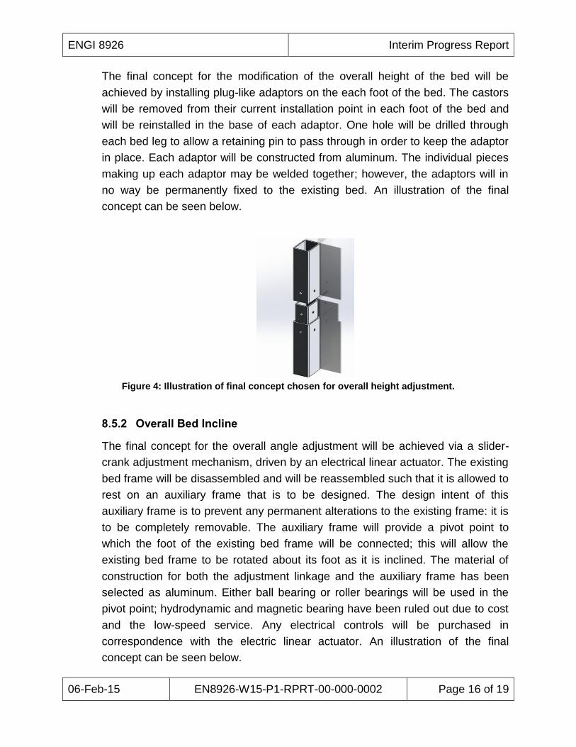
The final concept for the modification of the overall height of the bed will be
achieved by installing plug-like adaptors on the each foot of the bed. The castors
will be removed from their current installation point in each foot of the bed and
will be reinstalled in the base of each adaptor. One hole will be drilled through
each bed leg to allow a retaining pin to pass through in order to keep the adaptor
in place. Each adaptor will be constructed from aluminum. The individual pieces
making up each adaptor may be welded together; however, the adaptors will in
no way be permanently fixed to the existing bed. An illustration of the final
concept can be seen below.
Figure 4: Illustration of final concept chosen for overall height adjustment.
8.5.2 Overall Bed Incline
The final concept for the overall angle adjustment will be achieved via a slider-
crank adjustment mechanism, driven by an electrical linear actuator. The existing
bed frame will be disassembled and will be reassembled such that it is allowed to
rest on an auxiliary frame that is to be designed. The design intent of this
auxiliary frame is to prevent any permanent alterations to the existing frame: it is
to be completely removable. The auxiliary frame will provide a pivot point to
which the foot of the existing bed frame will be connected; this will allow the
existing bed frame to be rotated about its foot as it is inclined. The material of
construction for both the adjustment linkage and the auxiliary frame has been
selected as aluminum. Either ball bearing or roller bearings will be used in the
pivot point; hydrodynamic and magnetic bearing have been ruled out due to cost
and the low-speed service. Any electrical controls will be purchased in
correspondence with the electric linear actuator. An illustration of the final
concept can be seen below.

ENGI 8926 Interim Progress Report
06-Feb-15 EN8926-W15-P1-RPRT-00-000-0002 Page 17 of 19
Figure 5: Illustration of final concept chosen for overall bed incline.
8.5.3 Bed Rail Modification
The final concept selected for the rail modification is an inside rail enclosure
using clear Lexan sheets that are fastened with aluminum pop rivets and nylon
washers. An illustration of the final concept can be seen below.
Figure 6: Illustration of final concept chosen for bed rail modification.
8.5.4 Storage
The final design for the storage of medical equipment incorporates a wooden
shelving frame along the side length of the bed with wooden shelving walls that
can be moved along pilasters running perpendicular to the base allowing various
shelving widths to accommodate different size equipment needs. The shelving
walls will not go all the way to the back to allow room for cords and wires, six
wheels are included and aluminum angles are incorporated along the left, right
and back sides to stabilize the side panels and to keep things from falling out of
the back section of the base frame. Fabric organization bins will be incorporated
to be stored behind any equipment or in front of the empty shelving sections for
storage of linens or blankets. An illustration of the final concept can be seen
below.

ENGI 8926 Interim Progress Report
06-Feb-15 EN8926-W15-P1-RPRT-00-000-0002 Page 18 of 19
Figure 7: Illustration of final concept chosen for storage.
8.6 MISCELLANEOUS
Additional to the four main design changes it has been requested to incorporate a
detachable IV pole and it is desirable to incorporate a drop-down table to the head of
the bed and wire clips at various locations around/under the bed to keep wires tidy
and the end of the suction line clean.
9. CONCLUSION
A home hospital bed is to be modified to better suit the family of a 4 year old boy with
cerebral palsy. The required modifications involve additional overall bed height of 6-
inches, an adjustable overall bed incline option of up to 15-degrees, specialized
protective bed railings made from clear Lexan and storage for required important
medical equipment under the bed with an uninterrupted power supply. Final concepts
were determined that will lead to detailed design, fabrication and will be ultimately
installed for the existing hospital bed.
10. RECOMMENDATIONS
The next steps for this project involve fully defining detailed designs, purchasing
materials, fabricating designs and testing the final product prior to installation for the
client. It is desired to keep the permanent alterations to the existing bed to a minimum

ENGI 8926 Interim Progress Report
06-Feb-15 EN8926-W15-P1-RPRT-00-000-0002 Page 19 of 19
REFERENCES
[1] Virtual Expo, "Medical Expo - Hospital Beds," Virtual Expo , 1 February 2015. [Online]. Available: http://www.medicalexpo.com/medical-manufacturer/hospital-bed-13.html. [Accessed 1 February 2015].
[2] Virtual Expo, "Medical Expo - Hydraulic Hospital Beds," Virtual Expo, 1 February 2015. [Online]. Available: http://www.medicalexpo.com/medical-manufacturer/hydraulic-hospital-bed-540.html. [Accessed 1 February 2015].
[3] Truelife, "Hospital Equipment," Truelife, Dublin, 2015.
[4] Paragon Care, "Materials Handling," WebMagnet, 2 February 2015. [Online]. Available: http://www.paragoncare.com.au/medical-equipment/acute-care/materials-handling. [Accessed 2 February 2015].
[5] Invacare Canada, "Invacare Canada Home Care Beds and Bed-Related Accessories," Invacare Canada, Mississauga, 2007.
[6] Invacare Canada, "Owner's Operator and Maintenance Manual: IVC Bed Series: Full Electric Beds," Invacare Canada, Mississauga, 2007.
[7] Invacare Corporation, "Parts Catalog: Homecare Beds (Manual, Semi-Electric, Full Electric)," Invacare Corporation, Elyria, 2014.
[8] M. C. Staff, "Definition," 16 April 2013. [Online]. Available: http://www.mayoclinic.org/diseases-conditions/cerebral-palsy/basics/definition/con-20030502. [Accessed 5 Febuary 2015].
ENGI 8926 Interim Progress Report
06-Feb-15 EN7926-S14-P1-RPRT-00-000-0002 Page I of XVI
APPENDIX A: PROJECT MANAGEMENT PLAN
SCOPE OF WORK
The scope of work of J-MAT Consulting for this project is the design and fabrication of
specialized modifications to a pediatric hospital bed. This includes the lifting
mechanism, inclining mechanism, rail enclosure and equipment storage. Design of the
existing home hospital bed including original rails, actuation systems, and remote
controller are excluded from the scope of work. Fabrication will be provided by MUN
Technical Services who will volunteer their time and part of the materials. The
modifications are to be designed and fabricated under this scope of work to include the
above mentioned components.

ENGI 8926 Interim Progress Report
06-Feb-15 EN7926-S14-P1-RPRT-00-000-0002 Page II of XVI
TIME MANAGEMENT

ENGI 8926 Interim Progress Report
06-Feb-15 EN7926-S14-P1-RPRT-00-000-0002 Page III of XVI

ENGI 8926 Interim Progress Report
06-Feb-15 EN7926-S14-P1-RPRT-00-000-0002 Page IV of XVI
BUDGET MANAGEMENT
JMAT Consulting
PEDIATRIC HOSPITAL BED MODIFICATION
Feb-15
Project Manager - Ashley Sullivan
Income and Funding Income or Funding Source Amount
Faculty of Engineering $250
Tetra Society
Total Funding for Project $250
Expense Type of Expense Cost
Labor donated
Materials and Supplies $2,692
Misc. / 10% Contingency $269.15
Detailed Expense Type of Expense Cost
Test Setup Trial Building supplies, trailer jack, ancillary supplies $186
Total Bed Incline: Electric actuator & controls $600
Electric control box & hand controls $350
Aluminum rectangle tube $350
Aluminum rectangle bar $60
Bearings (including housing) $150
Shaft Couplings $200
Clevis Pins $15
Height Adjustment: Aluminum tubing (4') $30
Bed Rails: Lexan sheet (x2) $80
Aluminum pop rivets (x12) $2.50
Nylon washers (x12) $3
Storage: Wood (base x1 + shelves/ends x5 ) $200
Pilasters (x3) & Clips (x10) donated
Fabric organization bins (x4-5) $100
Uninterrupted Power Supply (UPS) $100
Aluminum angles (sides x2 & back x1) $60
Wheels (x6) $60
Miscellaneous: Wire Clips $20
IV Pole $75
Head board fold-down table (wood platform & hinges) $50
Total Project Expense $2,692
Total Project Budget $2,961
Note: This budget is current high level estimates of future costs, it is intended to acquire most building materials and all labor costs donated by local supply dealers and MUN Technical Services.

ENGI 8926 Interim Progress Report
06-Feb-15 EN7926-S14-P1-RPRT-00-000-0002 Page V of XVI
APPENDIX B: MORPHOGICAL CHARTS
OVERALL HEIGHT ADJUSTMENT
Table 1: Overall Height Adjustment Morph Chart.
Option 1 Option 2 Option 3 Option 4
Material Steel Aluminum Polymer Composite
Mount Location (leg)
Exterior Interior Both exterior &
interior
Mounting Mechanism
Clamp Screws Pins
OVERALL BED INCLINE
Table 2: Overall Bed Incline Morph Chart.
Option 1 Option 2 Option 3 Option 4 Option 5
Mechanism 4-Bar Slider Slider Crank w/ Power Screw
Slider Crank w/ Linear Actuator
Direct-Connected Linear Actuator
Headboard Scissor Lift
Material Steel Aluminum Composite (CF or fiber glass)
Polymer (HDPE, PTFE, etc.)
Motive Source Electric Hydraulic Pneumatic
Bearing Type Hydrodynamic Ball Roller Magnetic
Installation Removable Permanent
Installation Method
Bolt to existing Weld to existing
Clamp to existing
Angle Controller
Handheld, wired
Handheld, wireless
Bed-mounted
Angular Speed Control
Micro Controller
Personal Computer
Mechanical None
Angular Position Sensing
Optical Encoder
Limit Switches LVDT None
Torque/Force Limiting
Torque Switches
Limit Switches Shaft keys Frangible Shafts Press Fits
BED RAILS MODIFICATION

ENGI 8926 Interim Progress Report
06-Feb-15 EN7926-S14-P1-RPRT-00-000-0002 Page VI of XVI
Table 3: Bed Rail Modification Morph Chart.
Option 1 Option 2 Option 3 Option 4
Rail Enclosure
Cover inside of rail opening only
Cover inside and outside of rail opening
and rail handles
Cover outside of rail opening only
Cover inside and outside of rail
opening
Material Lexan
(Polycarbonate) Lexan (Polycarbonate)
& Rubber Acrylate Sheets
Clear Vinyl Sheets
STORAGE
Table 4: Storage Morph Chart.
Option 1 Option 2 Option 3 Option 4
Location of storage
Above bed Under foot Under head Along side
Material Aluminum Stainless Steel Plastic Wood
Shelving dividers
All open space – no dividers
Permanently spaced dividers
Open space with fabric storage bins
Adjustable width dividers
Shape of frame
Partial length & depth
Full length & partial depth
Partial length & full depth
Full length & depth
Power source Regular power
bar No internal power
supply Power supply with surge protection
UPS

ENGI 8926 Interim Progress Report
06-Feb-15 EN7926-S14-P1-RPRT-00-000-0002 Page VII of XVI
APPENDIX C: EVALUATION & SELECTION MATRICES
OVERALL HEIGHT ADJUSTMENT
Table 5: Material Selection Matrix for Overall Height Adjustment.
Aluminum Steel (REF) Composite Polymer
Weight Rate Score Rate Score Rate Score Rate Score
Strength 20.00% 2.5 0.5 2.5 0.5 1.5 0.3 1 0.2
Machinability 10.00% 2.5 0.25 2.5 0.25 2 0.2 2 0.2
Durability 10.00% 3 0.3 2.5 0.25 2.5 0.25 1.5 0.15
Corrosion Resistance 15.00% 2.5 0.375 2.5 0.375 5 0.75 5 0.75
Cost 20.00% 2 0.4 2.5 0.5 1 0.2 1.5 0.3
Compatibility with existing material 25.00% 4.5 1.125 2.5 0.625 4 1 5 1.25
Total Score TOTAL SCORE: 2.95 2.5 2.7 2.85
Table 6: Concept Selection Matrix for Overall Height Adjustment.
Concept 1 (REF) Concept 2 Concept 3
Weight Rate Score Rate Score Rate Score
Strength 20.00% 2.5 0.5 4 0.8 2 0.4
Machinability 10.00% 2.5 0.25 2 0.2 3 0.3
Durability 10.00% 2.5 0.3 3 0.3 2 0.2
Corrosion Resistance 15.00% 2.5 0.375 3 0.45 5 0.75
Cost 20.00% 2.5 0.4 1.5 0.3 2.5 0.5
Compatibility with existing material 25.00% 2.5 1.125 5 1.25 4 1
Total Score 2.95 3.3 3.15

ENGI 8926 Interim Progress Report
06-Feb-15 EN7926-S14-P1-RPRT-00-000-0002 Page VIII of XVI
OVERALL BED INCLINE
Table 7: Material Selection Matrix for Overall Bed Incline.
Selection Criteria
Weight
Steel (Reference)
Aluminum Composite Polymer
Score
Weighted Score
Score
Weighted Score
Score
Weighted Score
Score
Weighted Score
Strength 20% 2.5 0.5 2 0.4 1.5 0.3 1 0.2
Machinability 10% 2.5 0.25 2.5 0.25 1 0.1 2 0.2
Durability 10% 2.5 0.25 2.5 0.25 2.5 0.25 0.5 0.05
Corrosion Resistance
10% 2.5 0.25 4 0.4 5 0.5 5 0.5
Cost 20% 2.5 0.5 1.5 0.3 0.5 0.1 1 0.2
Compact. w/ Existing Material
20% 2.5 0.5 4 0.8 5 1 5 1
Availability of Manufacturing Resources
10% 2.5 0.25 2.5 0.25 0 0 0 0
Total Score 2.5 2.65 2.25 2.15
Table 8: Material Selection Matrix for Overall Bed Incline.
Selection Criteria
Weight
4-Bar Slider (Reference)
Slider-Crank Headboard Scissor Lift
Direct-Connected Actuator
Score
Weighted Score
Score
Weighted Score
Score
Weighted Score
Score
Weighted Score
Mechanical Simplicity
10% 2.5 0.25 4 0.4 4 0.4 5 0.5
Ease of Analysis
5% 2.5 0.125 4 0.2 4 0.2 5 0.25
Ease of Operation
10% 2.5 0.25 4 0.4 2.5 0.25 4 0.4
Ease of Maintenance
10% 2.5 0.25 3.5 0.35 2 0.2 5 0.5
Amount of Sliding Wear
20% 2.5 0.5 5 1 4 0.8 5 1
Compatibility with Hand Crank
25% 2.5 0.625 3 0.75 2.5 0.625 1 0.25
Actuator Cost
15% 2.5 0.375 1.5 0.225 2.5 0.375 1.5 0.225
Material Cost
5% 2.5 0.125 5 0.25 2.5 0.125 5 0.25
Total Score 2.5 3.575 2.975 3.375

ENGI 8926 Interim Progress Report
06-Feb-15 EN7926-S14-P1-RPRT-00-000-0002 Page IX of XVI
Table 9: Mechanism Selection Matrix for Overall Bed Incline.
Selection Criteria Weight
Electric (Reference) Hydraulic Pneumatic
Score Weighted
Score Score
Weighted Score
Score Weighted
Score
Total Cost 20% 2.5 0.5 1 0.2 1 0.2
Safety 50% 2.5 1.25 1 0.5 1.5 0.75
Ease of Design & Analysis
15% 2.5 0.375 2 0.3 1 0.15
Availability of Space 15% 2.5 0.375 2.5 0.375 1 0.15
Total Score 2.5 1.375 1.25
BED RAILS MODIFICATION
Table 10: Concept Screening Matrix for Bed Rail Modification.
Selection Criteria
Concepts
C1 C2
(Reference) C3 C4
Weight + 0 - -
Ease of Manufacture 0 0 - 0
Size + 0 0 -
Complexity 0 0 0 -
Durability - 0 - -
Transparency 0 0 0 0
Cost + 0 + +
Sum of “+” [A] 3 0 1 1
Sum of “0“ [B] 3 8 3 2
Sum of “-” [C] 1 0 3 4
Total [A-C] 2 0 -2 -3
Rank 1 1 2 3
Selection Yes Yes No No
Table 11: Concept Scoring and Selection Matrices for Bed Rail Modifications.
Selection Criteria
Concepts
Weight C1 C2
Rate Score Rate Score
Weight 10% 4 0.40 3 0.30
Size (Thinness) 10% 4 0.40 3 0.30
Manufacturability 10% 5 0.50 4 0.40
Simplicity 20% 3 0.60 3 0.60
Durability 25% 4 1.00 4 1.00
Transparency 15% 5 0.75 5 0.75
Cost 10% 4 0.40 3 0.40
Total Score 4.05 3.75
Rank 1 2
Selection Yes No

ENGI 8926 Interim Progress Report
06-Feb-15 EN7926-S14-P1-RPRT-00-000-0002 Page X of XVI
STORAGE
Table 12: Concept Screening Matrix for Storage.
Selection Criteria
Concepts
C1
C2 (Reference)
C3 C4
Weight + 0 + -
Ease of Manufacture
- 0 0 +
Size + 0 + -
Complexity - 0 0 0
Durability 0 0 0 0
Maintenance / Operation
- 0 + 0
Maneuverability - 0 - +
Cost - 0 0 0
Sum of “+” [A] 2 0 3 2
Sum of “0“ [B] 1 8 4 4
Sum of “-” [C] 5 0 1 2
Total [A-C] -3 0 2 0
Rank 3 2 1 2
Selection No No Yes Yes
Table 13: Concept Scoring and Selection Matrix for Storage.
Selection Criteria
Concepts
Weight C3 C4
Rate Score Rate Score
Weight 5% 5 0.25 5 0.25
Size 20% 4 0.8 5 1.0
Manufacturability 20% 5 1.0 5 1.0
Complexity 10% 4 0.4 3 0.3
Durability 10% 4 0.4 4 0.4
Maintenance / Operation
10% 2 0.2 5 0.5
Maneuverability 20% 1 0.2 4 0.8
Cost 5% 4 0.02 3 0.15
Total Score 3.37 4.4
Rank 2 1
Selection No Yes

ENGI 8926 Interim Progress Report
06-Feb-15 EN7926-S14-P1-RPRT-00-000-0002 Page XI of XVI
APPENDIX D: INVACARE 5410IVC HOSPITAL BED DATA SHEET

ENGI 8926 Interim Progress Report
06-Feb-15 EN7926-S14-P1-RPRT-00-000-0002 Page XII of XVI

ENGI 8926 Interim Progress Report
06-Feb-15 EN7926-S14-P1-RPRT-00-000-0002 Page XIII of XVI

ENGI 8926 Interim Progress Report
06-Feb-15 EN7926-S14-P1-RPRT-00-000-0002 Page XIV of XVI

ENGI 8926 Interim Progress Report
06-Feb-15 EN7926-S14-P1-RPRT-00-000-0002 Page XV of XVI

ENGI 8926 Interim Progress Report
06-Feb-15 EN7926-S14-P1-RPRT-00-000-0002 Page XVI of XVI