Embed Size (px)
Citation preview
R- 8298
LIQTJD ROCKET PERFORMANCE COMmpTER MODEL
W I T H DISTRIBUTED ENERGY RELEASE
INTERIM FINAL REPORT
C onkrac t NAS7- 746
E, P, combs W, De Chadwick De T, Campbell
https://ntrs.nasa.gov/search.jsp?R=19710000538 2020-05-08T11:54:49+00:00Z
R-8298
&I@JID ROCKET PERFORMANCE COMWTER MODEL
WITR DISTRIBU'I'ED ENERGY RELEASE
INTEJ3IM F m L REPORT
Le P, Combs W, D, Chadwick D. T. Campbell
prepared f o r
NATIONAL AEELONAUTICS AND SPACE ADMINISTRATION
11 September 1970
Contract NAS7-746
Technical Management Je t Pr opu 1s ion Lab or a t ory
Pasadena, California
Roc Ire t d yne i v i s i o n of North American R o c b e l l Corporation ,6633 Canoga Avenue, Canoga Park, California
i
T h i s r e p o r t w a s prepared by Rocketdyne, a Divis ion of North American
Rockwell Corporat ion, i n accordance wi th A r t i c l e 11, Paragraph D of
Contract No, US7-746 w i t h t h e Nat ional Aeronaut ics and Space Adminis-
t r a t i o n .
t h e r epor t .
15 Augus t 1970. The con t rac t was administered f o r NASA by t h e J e t
Propuls ion Laboratory, Pasadena, C a l i f o r n i a , whose Technical Manager
w a s Dr, Raymond Kushida.
Clapp and D r . David Campbell funct ioned as t h e Rocketdyne P ro jec t
Manager,
s u l t a n t s wi th r e spec t t o t h e t r anson ic and supersonic flow aspec t s of
t h e program.
A NASA con t rac to r r epor t (CR) number w a s not assigned t o
The con t r ac t per iod of performance w a s 15 August 1969 t o
The Rocketdyne Program Manager was Mr. Spencer
Mre J, C, Hyde and Mr. W, H, Moberly served a s va luable con-
ii

ABSTRACT
An a n a l y t i c a l computer program f o r performing l i q u i d rocke t engine per-
formance ana lyses w a s developed by modifying and combining e x i s t i n g
spray formation and subsonic combustion computer programs with r e fe rence
JANNAF ( I C R E ) computer programs f o r t r anson ic and supersonic nozzle
f l a w .
accounts a n a l y t i c a l l y f o r t h e combustion energy r e l e a s e l o s s e s r e s u l t i n g
from imperfect p rope l l an t spray mixing and incomplete spray g a s i f i c a t i o n
upstream of t h e nozzle t h r o a t ,
t r i b u t i o n s f r o m ind iv idua l i n j e c t i o n elements of given t y p e , des ign and
p o s i t i o n , t h e f i r s t program block c a l c u l a t e s b i p r o p e l l a n t spray d i s t r i -
b u t i o n , drop s i z e s and v e l o c i t i e s a t p o i n t s i n a co l l ec t ion -p lane , which
i s a l s o an i n i t i a l - p l a n e f o r spray combustion ana lys i s . The second
program block analyzes t h e spray burning and combustion product f low
from t h a t plane through t h e nozzle t h r o a t , us ing a mul t ip le axisymmetric
stream tube concept, In t h e nozz le , a s p a t i a l p re s su re d i s t r i b u t i o n is
imposed on t h e flow as ca l cu la t ed by a suppor t ing t r anson ic f low program
block. The f i n a l program block c a l c u l a t e s two-dimensional, axisymmetric
k i n e t i c expansion i n t h e nozzle d ivergent s e c t i o n of s t ream tube com-
b u s t i o n gases , wi thout f u r t h e r spray burning. Residual spray e n t e r i n g
t h i s s e c t i o n w a s simply t r e a t e d as mass t h a t i s l o s t and degrades bo th
c* and I e f f i c i e n c i e s ,
The new "Dis t r ibu ted Energy Release" (DEZ) computer program
Based on summing p rope l l an t spray con-
S
Program v e r i f i c a t i o n w a s sought by comparing p red ic t ed performance wi th
a v a i l a b l e experimental data, A f t e r some manipulation of spray c o l l e c t i o n
plane loca t ion drop s i z e formulas and method of i n i t i a l i z i n g s t ream
t u b e s , good agreement of c*-ef f ic ienc ies f o r FLOX/ p r o p e l l a n t s w a s
obtained, Parameters va r i ed were l ike-double t -pa i r i n j e c t i o n element
design d e t a i l s , chamber length and con t rac t ion r a t i o , chamber p re s su re
and mixture r a t i o , J u s t one of t h e s e cases w a s c a r r i e d through t o
complete c a l c u l a t i o n of Is; t h e ca l cu la t ed va lue w a s about 2$ h ighe r
than expected, Poss ib l e causes of t h i s discrepancy a r e d iscussed ,
iii
ii
iii
1
3 5 9
26
29
29
32
37 37 37 49
51 53 57
i v
INTRODUCTION
Combustion i n e f f i c i e n c i e s i n l i q u i d rocke t engines which r e s u l t from
incomplete spray evapora t ion , imperfect mixing between p rope l l an t sp rays
and t h e i r r e a c t i n g vapors and incomplete chemical r e a c t i o n of t h e com-
bus t ion products w i t h i n t h e combustion chamber have been termed "energy
r e l e a s e losses" . Such l o s s e s normally c o n s t i t u t e a major po r t ion of t h e
i n e f f i c i e n c y i n opera t ion of such rocke t engines, The cu r ren t JANNAF
r e fe rence method f o r performance a n a l y s i s (Ref a 1) accounts f o r energy
r e l e a s e l o s s e s i n an approximate, empir ica l manner by an a r b i t r a r y
reduct ion i n va lue of t h e i n i t i a l p rope l l an t enthalpy, Thus, a c t u a l
ho t f i r i n g t e s t da t ahave been r equ i r ed t o e s t a b l i s h apparent va lues
f o r t h e energy r e l e a s e lo s s .
This r e p o r t desc r ibes t h e development of an improved, phys ica l ly-base
a n a l y t i c a l approach wherein t h e s e l o s s e s a r e accounted f o r by incor -
po ra t ion of computer programs f o r b i p r o p e l l a n t spray combustion a n a l y s i s
i n t o t h e performance a n a l y s i s methodology. Because t h e spray burning
is d i s t r i b u t e d throughout t h e combustion chamber, t h e improved method
i s sa id t o have ( s p a t i a l l y ) d i s t r i b u t e d energy r e l e a s e ,
Q u a l i t a t i v e l y , energy r e l e a s e l o s s e s a s soc ia t ed wi th t h e phys ica l
p rocesses of a tomiza t ion , spray d i s p e r s i o n and mixing may be t r a c e d
back through t h e combustor and a t t r i b u t e d d i r e c t l y t o i n j e c t o r des ign
c h a r a c t e r i s t i c s . A major ob jec t ive of t h i s program w a s es tab l i shment
of q u a n t i t a t i v e , c a l c u l a b l e l i n k s between i n j e c t o r des ign d e t a i l s and
r e s u l t a n t performance lo s ses , Meeting t h i s ob jec t ive depends upon
c a p a b i l i t i e s f o r desc r ib ing and analyzing i n d e t a i l t h e na tu re and
behavior of i n j e c t e d s p r a y s 9 t h e i r subsequent vapor i za t ion and burning
and t h e gas dynamics of t h e multicomponent, mul t iphase , r e a c t i n g com-
b u s t i o n f i e l d ,
a p p l i c a t i o n t o a n a l y s i s of injector/chamber w a l l compa t ib i l i t y (Ref e 2)
as a s e r i e s of i n t e r - r e l a t e d computer programs, s o t h e approach taken in-
volved, t o a large degree , adapt ion of some of t hose computer programs
t o t h e performance a n a l y s i s problem. Cer t a in f e a t u r e s of t hose programs
Those c a p a b i l i t i e s hac% r e c e n t l y been developed f o r
1

were r e f ined and they were in t eg ra t ed wi th (1) an e x i s t i n g t r anson ic
a n a l y s i s program and (2) t h e JAMNAF r e fe rence method's two-dimensional
k i n e t i c program, which provided f o r a n a l y s i s of t h e supersonic nozzle
expansion processes ,
r e l e a s e performance model (Dm) and i t s i n i t i a l checkout and v e r i f i -
c a t i o n a r e descr ibed i n t h i s i n t e r i m f i n a l r epor t .
Formulation of t h e o v e r a l l d i s t r i b u t e d energy
The DER computer program has been de l ive red t o t h e J e t Propuls ion
Laboratory, t oge the r wi th suppor t ing documentation t o guide i t s usage
(Ref. 3) That documentation inc ludes p e r t i n e n t program d e s c r i p t i o n s
and l i s t i n g s , input da t a requirements , opera t ing i n s t r u c t i o n s and a
complete sample ca l cu la t ion .
2

I n formulat ing an a n a l y t i c a l d e s c r i p t i o n of l i q u i d rocke t engine com-
b u s t i o n and flow processes , it i s convenient t o subdivide t h e combustor
i n t o a series of d i s c r e t e zones, as shown i n Fig. 1 f o r a t y p i c a l
conf igura t ion , C e r t a i n l y , t r a n s i t i o n from one zone t o t h e next cannot
I-RAPlD r S T R E A N TUBE CONBUSTION COH~USTION
'INJECTION/ I ZONE / ZONE /BTRANSONIC FLOW ZONE
ATOMIZATION ZONE I I
I SUPERSONIC EXPANSION ZONE
I
\ SONIC FLOW LINE
CHAHBER CONBUSTION 4 REG I ON
Figure 1. Subdivis ion o f Combustion Chamber i n t o Zones' f o r Analysis
be sha rp ly de f ined , b u t i s gradual . The p o s i t i o n s and abruptness of
t h e s e t r a n s i t i o n s are inf luenced by des ign v a r i a b l e s , p rope l l an t
combination and opera t ing condi t ions , A few comments about each of
t h e s e zones are p e r t i n e n t before proceeding wi th d e s c r i p t i o n of t h e
computer model,
Immediately ad jacent t o t h e p rope l l an t i n j e c t o r t h e " in j ec t i o n zone" is l e a s t amenable t o a n a l y t i c a l d e s c r i p t i o n ,
i n j e c t i o n concentrated a t d i s c r e t e s i t e s , l a r g e g rad ien t s e x i s t i n a l l
dimensions wi th r e s p e c t t o p rope l l an t mass f l u x e s and concen t r a t ion ,
degree of a tomiza t ion and spray d i s p e r s i o n , and p r o p e r t i e s of t h e gaseous
medium,
burning rates a r e l o w , Gases i n t h i s zone a r e p r imar i ly e i t h e r gaseous-
i n j e c t a n t s o r r e c i r c u l a t e d combustion gases from t h e next zone downstream,
With l i q u i d
Spray d r o p l e t s here a r e usua l ly co ld s o t h e vapor i za t ion and
3

Completion of primary atomizat ion and convect ive hea t ing of sp ray drop-
l e t s enhance vapor i za t ion r a t e s , l ead ing t o comparatively high chemical
r e a c t i o n r a t e s i n t h e "rapid combustion zone". Upon burn ing , t h e volume
of a l i q u i d p rope l l an t element is increased 100-fold o r more, This
expansion f o r c e s t r a n s v e r s e flows from high-burning-rate sites t o low-
burn ing- ra te s i tes as w e l l as producing an axial a c c e l e r a t i o n ,
provides some mixing b u t t h e sprays fo l low t h e gases only s lugg i sh ly ,
s o spray mass f l u x g r a d i e n t s a r e p r i m a r i l y degraded by injector-imposed
geometric d i spe r s ion and i n t e r s p r a y mixing1- L a t e r a l gas f lows w i l l be
generated as long as apprec iab le spray f l u x g r a d i e n t s p e r s i s t , b u t
even tua l ly they become small compared wi th axial flow v e l o c i t i e s and
t h e combustion f i e l d t akea on a stream tube flow appearance.
This
I n t h e "stream tube combustion zone", t h e f l o w ' l a e k s t h e forced t r a n s -
ve r se convect ive components t h a t are dominant i n t h e e a r l i e r zones,
Continued mixing depends upon t u r b u l e n t exchange between neighboring,
pa ra l l e l - f l awing s t r i a t i o n s , b u t f low v e l o c i t i e s he re are h igh , resi-
dence times are s h o r t , and t u r b u l e n t mixing is no t very e f f e c t i v e , To
a good approximation, mixing can be e n t i r e l y neglec ted and t h e two-
phase f low t r e a t e d formal ly as stream tubes.
A s sprays a r e acce le ra t ed and dep le t ed , combustion ra te pe r u n i t chamber
length decays wi th inc reas ing d i s t ance , Chemical r e a c t i o n ra tes , on
t h e o the r hand, remain high w e l l i n t o t h e exhaust nozzleo Then as t h e
combustion products expand through t h e nozz le , diminishing p res su res
and temperatures lower t h e gas-phase chemical r e a c t i o n rates,
dimensional f low e f f e c t s a r e a l s o important i n t h e " t ransonic" and "super-
sonic flow'' zonesc For most high cornbustion e f f i c i e n c y r o c k e t s , spray
combustion e f f e c t s are n e g l i g i b l e compared wi th gas dynamic e f f e c t s
i n t h e s e downstream zones,
Two-
t ance of the. r a p jectian ~ . ~ e ~ e n t
4

Development of an a n a l y t i c a l model f o r t he o v e r a l l combustion process
i s made f e a s i b l e only by emphasizing t h e predominent mechanisms i n
each of t h e zones desc r ibed , a l lowing processes of secondary importance
t o be descr ibed approximately. For i n s t a n c e , spray vapor i za t ion is
most important i n t h e subsonic f law reg ions , where mult i -dimensional i ty
and chemical k i n e t i c e f f e c t s may be s impl i f i ed o r even neglec ted ,
Combustion models f o r much of t h e s e reg ions may be s t r u c t u r e d quasi-
one-dimensionally and emphasize t h e coupled spray-gas i n t e r a c t i o n s ,
A s another example, burning of r e s i d u a l sprays i n t h e nozzle d ive rgen t
s e c t i o n may o f t en be neg lec t ed , pe rmi t t i ng emphasis t o be placed on
two-dimensional gas dynamics wi th k i n e t i c a l l y - l i m i t e d r e a c t i o n r a t e s ,
These examples w i l l be recognized i n t h e s t r u c t u r e of t h e computer
program d e s c r i b ed be 1 ow.
COMPUTER MODE% STRUCTURE
A v e r b a l d e s c r i p t i o n i s given of t h e o v e r a l l computer program s t r u c t u r e
be fo re d e t a i l i n g t h e formulat ions for t h e va r ious combustor zones, Two
e x i s t i n g computer programs (both of which were presented and d iscussed
i n Ref. 2 and 4) have been modified and i n t e r f a c e d wi th J A W r e fe rence
computer programs, which have a l s o been modified somewhat. The system
of programs has then been l inked toge the r t o form a s i n g l e in t eg ra t ed
computer program, which is r e f e r r e d t o as DER (Di s t r ibu ted Energy
Release) I)
The DER computer program s t r u c t u r e is i l l u s t r a t e d i n Fig. 2, Analys is
begins wi th LISP (Liquid I n j e c t o r Spray P a t t e r n ) computer program
c a l c u l a t i o n s of spray mass f l u x e s , v e l o c i t y v e c t o r s and d r o p l e t d iameters
a t a l a r g e number of r,€I-mesh p o i n t s i n an " i n i t i a l - p l a n e " some s h o r t
d i s t a n c e downstream of t h e i n j e c t o r f a c e e These c a l c u l a t i o n s a r e
based on i n j e c t o r design d a t a (number and type of i n j e c t i o n elements ,
element l o c a t i o n s and o r i e n t a t i o n ) and empir ica l parameters which
5

v) I- - 0 CI
W Lr. v)
3 3 I-
W 0
e n
0

c o r r e l a t e a s i n g l e i n j e c t i o n e lement ' s spray mass f l u x d i s t r i b u t i o n and
mean d r o p l e t s i z e wi th i t s design and opera t ing parameters,
mations are a l s o made of p r o p e l l a n t vapor i za t ion (burning) which occurs
upstream of t h e i n i t i a l plane.
Approxi-
The output from LISP provides t h e necessary d e s c r i p t i o n of t h e two-
phase flow f i e l d f o r i n i t i a l i z i n g t h e s t ream tube combustion program
The assemblage of mesh po in t f low parameters i n t o s t ream tubes w a s
done recognizing t h e eventua l n e c e s s i t y of mating wi th e x i s t i n g ICRPG
r e fe rence nozz le a n a l y s i s programs. These ICRPG r e fe rence programs
desc r ibe axisymmetric, two-dimensional f l a w , i o e e , parameters do not
vary i n t h e 8 - d i r e c t i o n of an r , 8 , z - c y l i n d r i c a l coord ina te system,
Therefore , t h e LISP mesh po in t flows a r e conibined/averaged i n t h e
i n i t i a l plane t o i n i t i a l i z e t h e flaws i n t o a number of axisymmetric
stream tubes , Typica l ly , t h e r e a r e an order of magnitude fewer stream
tubes than mesh po in t s . To avoid excess ive degradat ion of t r a n s v e r s e
mixture r a t i o d i f f e r e n c e s , t h e annular stream tube flows a r e obtained
by a complicated breakdown i n t o a s e l e c t e d number of geometric zones,
w i t h i n each of which t h e mesh p o i n t flaws are c o l l e c t e d i n t o s t r e a m
tubes of l i k e mixture r a t i o .
1
Spray combustion downstream of t h e i n i t i a l p lane i s analyzed by a
s t ream tube combustion (STC) computer program,
sp rays and gases) which e n t e r 8 given s t ream tube a r e t h e r e a f t e r
P rope l l an t flows (both
This approach bypasses a n a l y s i s of t h e rap id combustion zone, For i n j e c t o r s w i th l a r g e t h r u s t e lements , r e l a t i v e l y few elements and/or ve ry non-unif orm spray mass d i s t r i b u t i o n s , t h i s omission may be s e r i o u s l y de t r imen ta l , computer program (3D-C$Ml3TJST), designed for analyz ing t h i s zone, has been developed (Ref, 2),
program, i t s omission is d iscussed b r i e f l y on page go
1
A three-dimensional combustion
Or ig ina l ly p ro jec t ed t o be u t i l i z e d
7

cons t ra ined t o flow i n t h a t t u b e , without exchanges of mass, momentum
o r energy among neighboring s t ream tubese The f law and combustion i n
each stream tube a r e analyzed by a one-dimensional formula t ion , wi th
l o c a l s t ream pa th as t h e independent v a r i a b l e , Stream path v a r i a t i o n s
wi th r-and z-coordinates are accounted for i n t h e nozzle , Solu t ion is
obtained by numerical i n t e g r a t i o n , marching i n t h e z -d i r ec t ion from
t h e i n i t i a l plane through t h e nozzle t h r o a t , The ind iv idua l stream
t u b e s ' s o l u t i o n s i n a plane are coupled through c o n s t r a i n t s on "area
c o n t i n u i t y f f and t h e r a d i a l p re s su re p r o f i l e .
cons tan t ac ross each z-plane u n t i l , a t some po in t i n t h e nozzle con-
vergent s e c t i o n , curva ture due t o t r a n s o n i c f low e f f e c t s i s taken i n t o
account.
s a t i s f i e s area c o n t i n u i t y , abso lu t e p re s su res are imposed upon t h e
so lu t ion .
computer program f o r a nea r ly equiva len t cons tan t f low r a t e , f rozen ,
homogeneous flow.
from t h e t r u e geometr ic flow area. The f r a c t i o n a l dev ia t ion of t h e
minimum value of t h a t sum from t h e nozzle t h r o a t area then i s used t o
a d j u s t t h e chamber p re s su re level f o r r e i t e r a t i o n through a l l or a
por t ion of t h e preceding combustion a n a l y s i s u n t i l t h e t h r o a t boundary
cond i t ion is s a t i s f i e d .
Pressure i s assumed t o be
Therea f t e r , r a t h e r t han cont inuing t o so lve for a p res su re which
These p re s su res a r e c a l c u l a t e d by a t r anson ic f low (TRANS)
The sum of t h e computed f low a r e a s may then d e v i a t e
A supersonic , i s o b a r i c s tar t l i n e f o r t h e ICRPG Two-Dimensional K ine t i c
(TDK) computer program (Ref, 5 ) i s then i n i t i a l i z e d from STC computed
d a t a i n t h e neighborhood of t h e nozz le t h r o a t . STC a n a l y s i s does no t
provide gas spec ie s concent ra t ion d a t a , s o t h e equi l ibr ium s e c t i o n of
K is used t o so lve f o r each stream t u b e ' s gas phase composition a t
t h e TDK star t l i n e , The "long-form opt ion" of is used t o cont inue
t h e m u l t i p l e axisymmetric stream tube a n a l y s i s through t h e supersonic
expansion processs
modified from t h a t given i n Ref, 5 * t h e i n i t i a l l i n e i s not analyzed f u r t h e r , b u t i s considered t o be flow
r a t e t h a t ' s l o s t t t h e gaseous expansion ana lys i s . It i s included
i n t h e c a l c u l a t i o n of s p e c i f i c impulse,
The subsequent TDK s o l u t i o n i s only s l i g h t l y
Residual unevaporated spray a t
8

Two d e s i r a b l e op t iona l o r a l t e r n a t e pa ths a r e ind ica t ed i n F i g o 2 f o r
f u t u r e i n c l u s i o n i n t h e DER computer program.
of f u l l i n j e c t o r cold-flow d a t a , would be u s e f u l f o r ana lyz ing s i tua-
t i o n s i n which s i n g l e element c o r r e l a t i o n s do no t e x i s t b u t f u l l i n j e c t o r
cold-flow d a t a do, The second, p rov i s ion of three-dimensional combustion
(3D-CQMsvST) a n a l y s i s of t h e e a r l y , r ap id spray combustion, is expected
t o be important for analyzing engines wi th moderately low performance,
p a r t i c u l a r l y when t h e r e a r e r e l a t i v e l y few i n j e c t i o n elements.
CQMEIUST w a s o r i g i n a l l y p ro jec t ed t o be u t i l i z e d i n DER. It w a s omitted
from t h e combined system of computer programs, however, because it had
not yet reached a developed, ope ra t iona l s t a t u s whereby i t s r e s u l t s
could be appl ied au tomat ica l ly t o STC and TDK c a l c u l a t i o n s wi thout
p r i o r eva lua t ion of those r e su l t s by an experienced ana lys t . Continued 1 improvement and usage of 3D-CQMBUST, e.g, , Rocketdyne c o n t r a c t u a l work
underway a t t h e t i m e of t h i s w r i t i n g , should b r i n g t h e program c l o s e r
t o such a s t a t u s .
The f i r s t , d i r e c t input
3D-
The LISP, STC and TDK computer program blocks have been r e t a i n e d as
s e p a r a t e , i d e n t i f i a b l e e n t i t i e s . Each h a s been modified somewhat t o
genera te d a t a needed by t h e fo l lowing program block and/or t o r e c e i v e
d a t a provided by i t s predecessw.
tapes .
ca rds by t h a t program block,
has no t been s o c l e a r l y r e t a ined . What l i t t l e input d a t a it needs a r e
read- in by STC and l a b e l common b locks a r e used t o t r a n s f e r d a t a between
These d a t a a r e t r a n s f e r r e d via s c r a t c h
Other d a t a r equ i r ed by a program block are read-in via punched
The i d e n t i t y of t h e TRANS program block
I n i t i a l i z a t i o n : LISP Computer Program
The LISP computer program i s descr ibed f u l l y i n Ref. 2 ,
summarization, condensed from Ref, 4 , i s given he re , The modi f ica t ions
'Contract No, F04611-70-C-0056, "Extension of I n j e c t o r Chamber Compat-
o r a t o r y , Edwards, C a l i f o r n i a , June 1970 i b i l i t y Analys is , between Rocketdyne and t h e A i r Force Rocket
9

requi red t o fit it i n t o t h e EEt computer program a r e a l s o
ind ica t ed
computer program c a l c u l a t e s spray mass f l u x e s a t mesh p o i n t s
(r, 8 , z o ) by t h e s t r a igh t fo rward summation of t h e mass f l u x e s from a l l
i nd iv idua l i n j e c t o r elements
which w a s f i r s t appl ied by Rupe (Ref. 6). (1) t h e ind iv idua l i n j e c t o r elements have p r e d i c t a b l e spray f l u x
p a t t e r n s which can be measured and c o r r e l a t e d ; (2) t h e ind iv idua l sp ray
p a t t e r n s of t h e va r ious elements a r e not des t royed , between t h e element
impingement p o i n t s and t h e plane z o 9 by c o l l i s i o n s between neighboring
f a n s ; and (3) vapor i za t ion of i p j e c t e d spray mass between t h e element
impingement p o i n t s and plane zo can be est imated.
The method can be used if:
The necessary c o r r e l a t i o n f o r wi ( r , e , z ) f o r use i n Eq, 1 i s based
upon t h e shape of s i n g l e element spray f l u x d i s t r i b u t i o n s determined
from cold-flow spray measurements. Flux p a t t e r n s were f i t t e d t o t h e
genera l ized expression:
0
which i s appl ied s e p a r a t e l y t o each p rope l l an t from an element.
(x ,y , z ) coord ina te system i n Eq, 2 i s re ferenced t o t h e element 's impinge-
men4 po in t f romwhieh i ts sp ray is presumed t o emanateo
c o e f f i c i e n t s a , b , ~ , , ~ ~ end C1 t h rou
as element type (duub
d iameter , impinging s t ream momenta, orifice l eng th , and manffold e f f e c t s e
The c o e f f i c i e n t s are obtained by c o r r e l a t i n g data from i n j e c t o r
s imula t ion t e s t s , i n which immiscible p r o p e l l a n t s imulants a r e c o l l e c t e d i n
a plane beneath t h e i n j e c t o r and measured,
The
The empir ica l
(2 &re func t ions of such parameters 6 e. ) i ~ i n g @ m @ n t ang le s o r i f i c e
The form of Eqe
10

w a s chosen because it s a t i s f i e s c o n t i n u i t y , p r e d i c t s t h e observed inve r se
square r e l a t i o n s h i p between mass f l u x and d i s t a n c e from t h e impingement
p o i n t , and because closed form i n t e g r a l s of Eq. 2 and i t s x and y moments
over t h e x , y p lane allow s t ra ight forward eva lua t ion of t h e empi r i ca l
c o e f f i c i e n t s , us ing experimental cold-flaw da ta ,
The LISP computer program t ransforms t h e x, y , z coord ina te systems of
t h e ind iv idua l elements t o t h e r , 8, z coord ina te system of t h e t h r u s t
chamber and then sums t h e spray mass f l u x e s from t h e ind iv idua l i n j e c t o r
elements t o each po in t i n a uniform mat r ix of mesh po in t s i n p lane z
Droplet v e l o c i t y v e c t o r s are c a l c u l a t e d using assumptions t h a t drops
t r a v e l as s t r a i g h t l i n e s between t h e impingement po in t and t h e mesh
p o i n t s i n z and t h a t t h e p r o p e l l a n t s ' i n j e c t i o n v e l o c i t i e s are con-
served by t h e drops.
0
0
Calcu la t ion of mean p rope l l an t d r o p l e t diameters u t i l i z e s empir ica l
equat ions r e l a t i n g them t o i n j e c t i o n element ho le s i z e s and i n j e c t i o n
v e l o c i t i e s .
w i th molten wax j e t s (Ref. 7 ), c o r r e c t i o n s account ing f o r d i f f e r e n c e s
i n l i q u i d and gas p r o p e r t i e s between those experiments and t h e combustor
are a l s o appl ied.
Since t h e equat ions were der ived from cold-flow s t u d i e s
Par t ia l p rope l l an t evaporat ion upstream of z
f i e d , i n t e g r a t e d evaporat ion express ion
i s ca l cu la t ed by a s impli- 0
where w ' is t h e l i q u i d spray f l u x a c t u a l l y a r r i v i n g a t t h e p o i n t
(r , 0 , z0). The c o e f f i c i e n t C k l i s r e l a t e d t o t h e evaporat ion coef-
f i c i e n t k ' used i n t h e subsequent sp ray combustion a n a l y s i s , However,
because t h e l i q u i d sprays a r e not f u l l y atomized over t h e e n t i r e A Z
d i s t a n c e , values of C inc luding a convect ive Nussel t number, a r e
usua l ly assumed t o be only about 115 t o 114 of t h e s t a g an t values of
kIr
summed over a l l mesh p o i n t s t o y i e l d a s i n g l e o v e r a l l vapor flow ra te
k' '
The p r o p e l l a n t vapors s a i d t o be generated by t h i s c a l c u l a t i o n a r e
f o r each p rope l l an t , Use of such a s impl i f i ed evaporat ion express ion i s ,
t o some e x t e n t , j u s t i f i e d by t h e re la t ively small percentage of evapora-
t i o n i n t h e spray formation zone. 1

Input t o t h e LISP computer program c o n s i s t s of t h e number, l o c a t i o n or ien-
t a t i o n , s i z e , geometry, and type of i n j e c t o r e lements , t oge the r wi th t h e
geometry of combustion zone mesh network and genera l d a t a concerning t h e
p rope l l an t d e n s i t i e s and i n j e c t o r p re s su re drops. Up t o 50 i n j e c t o r
elements can be considered toge the r w i th a s many as 400 combustion zone
mesh po in t s ,
For DER u t i l i z a t i o n t h e LISP main computer program w a s converted t o a
subrout ine which gene ra t e s a s c r a t c h t a p e record of each mesh p o i n t ' s
l o c a t i o n , reduced spray f l u x e s , spray d r o p l e t diameters and spray v e l o c i t y
vec to r s and, f o r t h e e n t i r e chamber segment cons idered , t o t a l and g a s i f i e d
p rope l l an t f low r a t e s .
program as a po r t ion of i t s input da t a .
The sc ra t ch t a p e i s subsequent ly read by t h e STC
Other modi f ica t ions were made t o s e v e r a l subrout ines i n LISP. P r imar i ly ,
t hese d e a l t wi th incorpora t ion of more cu r ren t mean p rope l l an t drop s i z e
equat ions f o r l ike-double t and l ike-double t -pa i r i n j e c t i o n elements and
wi th spray f l u x d i s t r i b u t i o n c o e f f i c i e n t s f o r l ike-double t -pa i r elements.
These are t h e i n j e c t o r types t e s t e d i n h o t - f i r i n g experiments whose r e s u l t s
were used f o r comparative v e r i f i c a t i o n ana lyses , as discussed l a t e r .
Axia l Marching: STC Computer Program
The STC computer program f o r multiple-stream-tube b i p r o p e l l a n t spray
combustion i s an ex tens ion t o axisymmetric flow and t r anson ic nozz le flow
of t h e STRMTB computer program descr ibed i n Ref. 2 and 4. These exten-
s i o n s complement each o ther : t h e assumption t h a t s t ream tubes a r e ax i -
symmetric annular c y l i n d e r s provides p o s i t i o n a l information which, i n
t u r n , makes it p o s s i b l e t o impose r e a l i s t i c two-dimensional t r a n s o n i c
pressure p r o f i l e s on t h e s t r e a m t u b e s .
s a t i s f y q u i t e c l o s e l y t h e nozzle boundary condi t ion of gas f l u x maximi-
z a t i o n a t t h e t h r o a t plane. Add i t iona l ly , s t ream tube pa th length
v a r i a t i o n s can r e a d i l y be taken i n t o account.
A s a r e s u l t , STC s o l u t i o n s can
A n a l y t i c a l model s o l u t i o n s a r e obtained numerical ly f o r s e v e r a l systems (one f o r each s t ream tube) of simultaneous ord inary d i f f e r e n t i a l
and a lgeb ra i c equat ions by s t a r t i n g wi th known condi t ions a t t h e
ISP i n i t i a l - p l a n e and marching downstream i n small a x i a l s t e p s e
12

The degree of s a t i s f a c t i o n of t h r o a t boundary condi t ion depends upon
t h e cons is tency of t h e i n i t i a l da t a ,
program w a s p rov i s ion f o r adjustment of i n i t i a l - p l a n e p res su re and
r e i t e r a t i o n through a l l or p a r t of t h e a n a l y s i s t o improve t h e matching
of t h a t boundary condi t ion ,
A f u r t h e r ex tens ion f o r t h e STC
t h The system of equat ions f o r t h e i- stream tube is:
Gas Phase
Con t inu i ty :
- u.A ) = As ($n)i i n , j d s 1 si
Momentum :
Adiabat ic Energy Equation: n
- 1 = T .f.- Y i Ti oi
where
=ri Ru T o i M a o i w i
(4)
(7)
The l o c a l stream tube gas mixture r a t i o is obtained simply by i n t e g r a t i n g
t h e evaporat ion r a t e s t o g e t g a s i f i e d f lowra tes :
'These combustion gas p r o p e r t i e s are obtained from sepa ra t e c a l c u l a t i o n of equi l ibr ium chamber cond i t ions f o r s e v e r a l mixture r a t i o s and t h e nominal chamber p re s su re f o r a p a r t i c u l a r case be ing analyzed,
neglec ted ,
They are a l s o ly weak func t ions of chamber p re s su re , b u t t h i s dependence is
i x t u r e Rat io :
S t a t e :
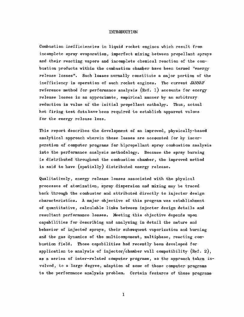
S w a y Phase
Mass Continui ty:
(nth d r o p l e t s i z e group of jth p r o p e l l a n t )
Drop Number Continui ty:
o r , equ iva len t ly ,
)i = (N .n)i (u. .n)i = cons tan t dJ dJ i
('dj
Momentum:
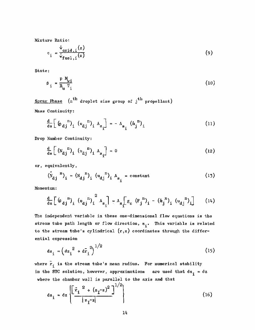
The independent v a r i a b l e i n t h e s e one-dimensimal flow equat ions is t h e
s t ream tube pa th length o r f low d i r e c t i o n , si"
t o t h e stream tube s c y l i n d r i c a l (r , a ) coord ina tes through t h e d i f f e r -
e n t i a l express ion
This v a r i a b l e is r e l a t e d
where E. i n t h e STC s o l u t i o n , however, approximations
where t h e chamber w a l l i s p a r a l l e l t o t h e axis an
i s t h e s t ream t u b e ' s mean rad ius . For numerical s t a b i l i t y i are used t h a t dsi = dz
14

i n t h e nozzle,
Fig. 9. e basis f o r E q , 16 may be seen by examinin
I n t h i s formula t ion , A appears as a dependent v a r i a b l e f o r which a
s o l u t i o n i s t o be found, The gas phase equat ions a r e cons t r a ined , however,
i n terms of z-plane a rea :
'i
Therefore , t h e foregoing equat ions were modified f o r t h e computer
program t o permit d i r e c t soludiion f o r A by s u b s t i t u t i n g : zi
A = A Z z dz
i i S
n
and n e g l e c t i n g t h e s t ream pa th curva ture by saying: - d'z - - 0, ds2
The sets of gas and l i q u i d phase equat ions a r e coupled through mass
and momentum exchange between phases. For d r o p l e t g a s i f i c a t i o n , t h e
simple evaporat ion c o e f f i c i e n t model i s u t i l i z e d :
where t h e evaporat ion c o e f f i c i e n t is
k
Td AH, +JT c dT d T --
n
Td 'v k'S
and n j
Nu = 2 + 0.53 Re j
Drag f o r c e s on spray d r o p l e t s are expressed by
15
Nozzle Wall
E
Figure 3. Schematic Illustration of Variables Denoting Local Conical Convergence of Stream Tubes

with t h e drag c o e f f i c i e n t s p e c i f i e d as
\
n -Oe84 = 24 (Re.n) ; Re 5 80 n
3 j .i cD -
n ; Re > 80 0,217
j = 0,271 (Re .”)
J
Input t o the STC computer program c o n s i s t s of chamber w a l l p r o f i l e , pro-
p e l l a n t p r o p e r t i e s , combustion gas p r o p e r t i e s and e i t h e r (1) i n i t i a l -
plane gaseous f lowra te and mixture r a t i o and spray f lowra te s , v e l o c i t i e s ,
and d r o p l e t diameters f o r a l l spray size-groups en te r ing each s t ream tube
o r (2) d a t a from LISP from which t h e s e v a r i a b l e s can be ca l cu la t ed ,
t o 40 stream tubes can be i n i t i a l i z e d wi th as many as 12 spray s i z e -
groups ( fue l and ox id ize r combined),
Up
Stream Tube I n i t i a l i z a t i o n , Data t r a n s f e r r e d t o STC from LISP a r e spray
mass f l u x e s , v e l o c i t i e s and mean d r o p l e t diameters a t each (r,e) mesh
po in t and f u e l and ox id ize r c o n t r i b u t i o n s t o t o t a l i n i t i a l - p l a n e gaseous
f l a w r a t e e I n a pre l iminary ve r s ion of t h e program, axisymmetric stream
tubes were formed by a s t ra ight forward combining of spray f lows f o r a l l
mesh p o i n t s a long each r = cons tan t c i r c l e of mesh p o i n t s i n t o a s i n g l e
s t ream tube, The i n i t i a l gas f l u x w a s assumed t o be uniform and homo-
geneous, This i n i t i a l i z a t i o n method w a s found t o introduce a substan-
t i a l amount of mixture r a t i o averaging around each annulus when appl ied
t o i n j e c t o r s which produce angular g r a d i e n t s i n l o c a l spray mixture
r a t i o b
combustion e f f i c i e n c i e s of 93 t o 95 percent were overpredicted by as
much as two percent . Thus, more complicated ways were inves t iga t ed f o r
i n i t i a l i z i n g an order of magnitude fewer s t ream tubes than i n i t i a l -
p lane mesh p o i n t s without causing excess ive mixing.
For some cond i t ions evaluatetd dur ing program development,
The method which w a s ult imately se l ec t ed provides a non-uniform d i s t r i -
bu t ion of gases as w e l l as of sprays , Gas mass f l u x e s a r e i n i t i a l l y
approximated as be ing uniform a t a l l mesh p o i n t s and then are ad jus ted
t o s a t i s f y s p e c i e s c o n t i n u i t y requirements.
s u b s c r i p t s i and j correspond t o LISP mesh p o i n t i nd ices , Uniform
gas mass f l u x is given by:
t h e f ollawing equat ions

Then t h e gas mixture r a t i o a t each mesh po in t i s s a i d t o be equal t o
t h e spray mixture r a t i o the re :
'oi ,.i wF
- C - i j
i j (23)
I n gene ra l , however, t h e s e two assumptions w i l l no t be compatible wi th
conserva t ion of p rope l l an t spec ie s flow r a t e s , eOg.:
(24 )
Therefore , t h e f u e l and ox id ize r con t r ibu t ions t o each mesh p o i n t ' s
gas f low a r e sca l ed s e p a r a t e l y t o preserve spec ie s con t inu i ty :
These d e f i n i t i o n s complete t h e s p e c i f i c a t i o n of p rope l l an t flows a t
each mesh poin t .
Mesh p o i n t f lows a r e combined i n t o s t ream tubes on bases of bo th posi-
t i o n and l o c a l mesh p o i n t mixture r a t i o .
boundary s t ream tube i s formed by comhining t h e chamber w a l l mesh
p o i n t s and perhaps one or more c i r c l e s of mesh p o i n t s ad jacent t o t h e
w a l l on a s t r i c t l y geometric b a s i s , I f t h e sum of t h e w a l l mesh p o i n t
f lows does not exceed 8 percent of t h e t o t a l p rope l l an t i n j e c t i o n r a t e ,
t h e next inward c i r c l e of mesh p o i n t s i s incorpora ted i n t o t h e w a l l
F i r s t , a chamber w a l l
18

boundary s t ream tube , e t c . This method p rese rves t h e angular averaging
objected t o be fo re , b u t it is accepted f o r a f r a c t i o n of t h e flow i n
order t o g e t a w a l l s t ream tube t h a t ' s c h a r a c t e r i s t i c of t h e mean w a l l
mixture r a t i o .
The remaining c i r c l e s of mesh p o i n t s a r e then subdivided i n t o a few
(perhaps 3 t o 5 ) r a d i a l zones having roughly equal p rope l l an t f low
r a t e s B Within each of t hese zones, t h e mesh po in t f lows a r e accumulated
according t o mixture r a t i o ( r a t h e r than p o s i t i o n ) i n t o s e v e r a l (perhaps
5 t o 7) st ream tubes wi th roughly equal f low r a t e s , These s t ream tubes
a r e then a r b i t r a r i l y ass igned r a d i a l p o s i t i o n s w i t h i n t h e conf ines of
t h e i r r e s p e c t i v e zones, V e r i f i c a t i o n t e s t ca ses d iscussed l a t e r were
analyzed us ing 19 s t ream tubes (one a t t h e w a l l p lus s i x per zone i n
t h r e e r a d i a l zones),
Method of Solu t ion , The numerical i n t e g r a t i o n scheme used t o so lve
each s t ream t u b e ' s s y s t e of equat ions is t h e s imples t f i r s t - o r d e r
Runge-Kutta (o r Eu le r ) method,
data s to rage requirements , l o w execut ion t imes and numerical s t a b i l i t y ,
t h i s method's accuracy i s str ngly dependent upon us ing s u f f i c i e n t l y
small s t e p s i z e s , This l i m i t a t i o n is reduced i n importance by using
backwards d i f f e r e n c i n g i n w r i t i n g f i n i t e - d i f f e r e n c e equat ions and by
so lv ing t h e equat ions tw ice , us ing p red ic t ed va lues from t h e f i r s t ,
o r p r e d i c t o r , s o l u t i o n a s input d a t a f o r a second, c o r r e c t o r , s o l u t i o n ,
Se lec ted f o r i t s s i m p l i c i t y , minimal
The STC program is f i r s t run i n a s i n g l e s t ream tube mode, i e e a a one-
dimensional subsonic combustion a n a l y s i s i s made f o r t h e e n t i r e chamber
us ing appropr i a t e sums and averages of i n i t i a l s t ream tube v a r i a b l e s ,
This i s done f o r t w o reasons: (1) t o v e r i f y cons is tency of i npu t d a t a
( i n i t i a l - p l a n e p res su re i s ad jus ted u n t i l t h e one-dimensional t h r o a t
v e l o c i t y i s w i t h i n a s m a l l t o l e r a n c e of t h e c a l c u l a t e d t h r o a t sound
speed) , and (2) t o provide a mean a d i a b a t i c expansion c o e f f i c i e n t , y o
f o r combustion gas f low i n t h e convergent p a r t of t h e exhaust nozz les
-
19
The l a t t e r c o e f f i c i e n t i s given by:
where t h e s u b s c r i p t 1 r e f e r s t o t h e beginning of nozzle convergence,
t h e v a r i a b l e s p* and p* a r e a t son ic flow cond i t ions and t h e over-bars
r e f e r t o t h e one-dimensional f low ana lys i s . It is used by t h e TRAm
computer program (descr ibed i n t h e next subsec t ion) t o c a l c u l a t e t h e
coord ina tes of cons tan t pressure su r faces ( i soba r s ) f o r t r a n s -
sonic f l aw i n t h e nozzle ,
t o STC i n non-dimensional terms, s o t h e i r use i n STC r e q u i r e s knowledge
of t h e nozzle t h r o a t r a d i u s , I$, (an input parameter) , and sonic flow
p res su re , p*, Discussion of t h e eva lua t ion of p* i s included i n t h e
fo l lowing o u t l i n e of STC's mul t ip l e s t ream tube so lu t ion ,
TRANS i s o b a r s a r e generated and t r a n s f e r r e d
Following STC averaged s i n g l e s t ream tube a n a l y s i s and TRANS a n a l y s i s ,
t h e i n i t i a l plane i s r e i n i t i a l i z e d wi th i t s o r i g i n a l input and t h e STC
program i s run i n a mul t ip l e s t ream tube modes Sequent ia l ly :
1, The main i t e r a t i o n loop performs t h e z d i r e c t i o n marching.
begins wi th e s t ima tes t h a t t h e changes i n chamber p re s su re , stream
tube gas v e l o c i t i e s and d e n s i t i e s ac ross t h e next Az increment are
equal t o t h e i r g rad ien t s i n t h e preceding s i n g l e s t ream tube
a n a l y s i s e
It
2, These es t imated p r o p e r t i e s are used t o c a l c u l a t e p red ic t ed va lues
f o r a l l spray behavior parameters. Drag, evaporat ion and o the r
sp ray d r o p l e t s i z e group parameters are computed wi th c o n t r o l s t o :
(1) l i m i t evaporat ion i f it is found t o exceed t h e amount of spray
a v a i l a b l e , and (2) avoid having t h e s i g n of [us - (uiijn)s] change i n a non-physical way due t o overes t imat ion
of drag f o r c e s , i o e o , d r o p l e t s cannot a c c e l e r a t e o r d e c e l e r a t e
p a s t t h e gas v e l o c i t y w i t h i n a given B z ,
20

30
4.9
5.
6 ,
7.
Evaporated sprays a r e added t o t h e previous g a s i f i e d p rope l l an t
sums and t h e gas phase mixture r a t i o s a r e computed, Combustion gas
p r o p e r t i e s corresponding t o t h e s e mixture r a t i o s are obtained by
l i n e a r i n t e r p o l a t i o n i n t h e p r o p e r t i e s t a b l e ,
a r e then made of gas temperatures , d e n s i t i e s , and stream tube a r e a s e
Spray g a s i f i c a t i o n and drag terms a r e next t r e a t e d as known con-
s t a n t s i n an i m p l i c i t - e x p l i c i t two-step s o l u t i o n f o r t h e gas phase
p r o p e r t i e s , s t ream tube f l aw areas and chamber p re s su re i n plane z2"
In t h e first s t e p , a pressure l e v e l i n plane z
t o c a l c u l a t e a p red ic t ed d i s t r i b u t i o n of stream tube a r e a s i n t h a t
plane.
t o be v a l i d , making poss ib l e an e x p l i c i t s o l u t i o n f o r t h e gas
tempera tures , d e n s i t i e s and p res su re a t z2"
The foregoing paragraphs 2, 3, and 4 desc r ibe a p r e d i c t o r c y c l e p
Thei r c a l c u l a t i o n s a r e repea ted i n a c o r r e c t o r cyc le , u s ing t h e
p r e d i c t o r c y c l e ' s c a l c u l a t e d z2-plane r e su l t s i n s t e a d of t h e
es t imated p r o p e r t i e s (paragraph 1).
group i s c a l c u l a t e d i n t h e c o r r e c t o r cyc le t o exceed t h e t o t a l mass
of t h a t group, t h e group i s said t o be completely g a s i f i e d ,
improved accuracy, a use r may e l e c t t o perform a d d i t i o n a l c o r r e c t o r
c y c l e s a )
A t t h i s p o i n t , normal program flow is p r i n t o u t of computed d a t a a t
plane z2$ r e i n i t i a l i z a t i o n of plane z1 a t p lane z2 f o r a new Az
and progress ing aga in through t h e paragraph 1 through paragraph 5 computations. Th i s procedure would cont inue a l l t h e way t o t h e
nozz le t h r o a t f o r non-axisymmetric s t ream tubes,
axisymmetric annular stream tubes , however, t h e procedure i s changed
a t t h e p o s i t i o n i n t h e nozzle where curva ture of t h e i s o b a r i c
s u r f a c e s i s introduced,
An approximate value of p* is es t imated from t h e nozzle t h r o a t
p lane p res su re of t h e preceding averaged, s i n g l e stream tube
Corrected e s t ima tes
i s assumed i n order 2
I n t h e second s t e p , t h a t d i s t r i b u t i o n of a r e a s i s assumed
I f evaporat ion of a sp ray
(For
With
= i* p(zQ)/&o),
TC i n i t i a l i z a t i o n plane, By mul t ip ly ing t h e reduced
21
pres su res , p/p*, of t h e TRANS i s o b a r s by t h i s va lue of p*cp abso lu te
p re s su res a r e ca l cu la t ed f o r t h e t r anson ic flow f i e l d , These are
imposed upon t h e mul t ip l e s t ream tube nozzle flow.
The f u r t h e s t upstream T a N S i soba r may be p l ana r or curved,
depending upon t h e n o z z l e ' s r a d i u s r a t i o and shape of i t s conver-
gent s e c t i o n o If it i s curved, i t i s d e s i r a b l e t o in t roduce a
gradual t r a n s i t i o n from p lana r i s o b a r s t o t h a t f i r s t curved i soba r
t h a t t h e s o l u t i o n encounters. Also , a gradual t r a n s i t i o n i s
d e s i r a b l e t o smooth out any d i s c o n t i n u i t y i n p re s su re l e v e l s
between those solved f o r upstream and imposed downstream of t h e
t r a n s i t i o n . The gradual t r a n s i t i o n i s provided by s topping t h e
s o l u t i o n f o r p re s su re l e v e l a t a p o s i t i o n t h a t i s upstream of t h e
nozzle t h r o a t by 1.3 t i m e s t h e a x i a l d i s t a n c e t h a t t h e f u r t h e s t -
upstream TRANS i soba r i n t e r s e c t s t h e nozzle w a l l , and us ing l i n e a r
i n t e r p o l a t i o n t o impose abso lu te p re s su res over t h e t r a n s i t i o n i n t e r v a l .
I n t h e t r a n s o n i c r eg ion , imposi t ion of abso lu t e p re s su res makes
t h e paragraph 4 s o l u t i o n f o r p re s su re l e v e l redundant , s o t h a t t h e
gas phase c a l c u l a t i o n is reduced t o a one-step, e x p l i c i t y s o l u t i o n
f o r s t ream tube areas. Because abso lu te p re s su res have been imposed,
t h e s o l u t i o n now provides abso lu te va lues of s t ream tube a r e a s
and t h e s e may o r may not sum t o t h e l o c a l nozzle flow a r e a ( i e e e ,
s a t i s f y a r e a con t inu i ty ) , By t h i s method, a r e a c o n t i n u i t y can be
s a t i s f i e d only by f i n d i n g t h e appropr i a t e va lue of p* t o d e f i n e
t h e proper nozzle p re s su re l e v e l .
8. A s t h e s o l u t i o n marches through t h e t r a n s o n i c flow regime, t h e
minimum value of t h e sum of t h e c a l c u l a t e d s t ream tube a r e a s a t
any preceding z-plane i s s tored . L a t e r , a f t e r t h e s o l u t i o n has
reached a z-plane t h a t ' s wholly downstream of the TRANS i soba r
which i n t e r s e c t s t h e nozzle w a l l a t t h e t h r o a t (TDK s t a r t - l i n e ) ,
t h i s minimum a r e a sum i s compared wi th t h e input geometric a r e a
of t h e nozzle t h r o a t .
a o n s t i t u t e s s aCi s fac f i en of t h e nozz le t h r o a t boundary
cond i t ion , )
i npu t t o l e r a n c e , e~~~ t h e
(It i s t h e match of t h e s e a r e a s t h a t
f t h e f r a c t i o n a l dev ia t ion i s l e s s t han some
M s t a r t - l i n e is i n i t i a l i z e d ,

t h e dev ia t ion l ies between one and t h r e e t imes EA^, i s ad jus ted and t h e s o l u t i o n i s r eca l cu la t ed from t h e po in t i n t h e
nozzle where abso lu te p re s su res were imposed. For dev ia t ions exceeding
3 G A ~ , mu l t ip l e s t ream tube s o l u t i o n i s r e c a l c u l a t e d ,
t h e va lue of p*
t h e STC i n i t i a l - p l a n e p res su re i s ad jus ted and t h e e n t i r e
Transonic Nozzle Flow: TRANS Computer Program
The re ference TDK computer program (Ref, 5 ) has a t r anson ic f l aw
a n a l y s i s s e c t i o n which, among o ther c a l c u l a t i o n s , p rovides , r , z -coor-
d i n a t e s of an i s o b a r i c s t a r t - l i n e f o r t h e supersonic expansion. This
s e c t i o n w a s i n i t i a l l y removed from t h e TDK program and modified s o t h a t
it generated a fami ly of as many as twenty i s o b a r i c l i n e s throughout
t h e t r anson ic flow regime. The necessary inpu t data were suppl ied from
t h e averaged, s i n g l e stream tube s o l u t i o n of STC, s o t h i s i n i t i a l TRANS
program gave a homogeneous f law so lu t ion . Its a p p l i c a t i o n w a s l imi ted
j u s t as it w a s i n TDK, t o nozzles whose r a t i o s of th roa t - rad ius-of -
curva ture t o throat-opening r a d i u s a r e not smaller than two .
The r e s t r i c t i o n on nozzle r a d i u s r a t i o subsequent ly has been re laxed
(Ref, 8) by r ep lac ing t h e foregoing t r anson ic f l a w a n a l y s i s s e c t i o n of
TDK wi th a new s e c t i o n based on a s o l u t i o n method (Ref. 9) which g ives
s t a b l e s o l u t i o n s f o r homogeneous f laws wi th r a d i u s r a t i o s as small as
5/8, second ve r s ion of TRANS f o r DER program usage. This second ve r s ion i s
h e r e a f t e r r e f e r r e d t o as the TRANS computer program.
That improved replacement s e c t i o n of TDKwas modified t o obta in a
A s input d a t a , TRANS needs values only of t h e nozzle t h r o a t r a d i u s ,
and a mean expansion c o e f f i c i e n t , y e I soba r i c coord ina tes a r e calcu-
l a t e d i n terms of a x i a l d i s t a n c e , X , from t h e t h r o a t plane and r ad ia l
d i s t a n c e , R, from t h e nozzle a x i s ; both dimensions are normalized t o t h e
t h r o a t r a d i u s l t i p l e i soba r s a r e genera ted , one a t a t ime, by start-
ing downstream of t h e t h r o a t and marching upstream wi th equal i n t e r v a l s ,
-

&CY,, i n t h e angle between t h e nozzle a x i s and a l i n e tangent t o t h e
nozzle w a l l a t t h e isobar/wal l i n t e r s e c t i o n p o i n t ,
tu red such t h a t t h a t i n t e r s e c t i o n poin t f o r t h e f i f t h i soba r i s a t t h e
t h r o a t ; t h i s i soba r l a t e r becomes t h e TDK s t a r t - l i n e ,
i n t e r s e c t i o n p o i n t s l i e downstream of t h e t h r o a t b>O) and t h e remainder
l i e upstream of t h e t h r o a t
i s given by:
The program is s t r u c -
Four isobar/wal l
O ) , The angular i n t e r v a l between i s o b a r s
28
Generation of isobars cont inues until e i t h e r (1) t h e r e are twenty of
them or (2) an i soba r e x h i b i t s s ign i f i cank r e v e r s e , or upstream curva-
t u r e o I n t h e l a t t e r c a s e , t h a t las t upstream-curving i soba r i s
rep laced wi th a p l ana r s u r f a c e r
Two computer-plotted examples from TRANS analyses a r e shown i n F ig . 4, where: t h e nozzle a x i s is a t t h e bottom (R/RT = 0); flow d i r e c t i o n is
from l e f t t o r i g h t ; a po r t ion of t h e nozzle w a l l , def ined by - 30" 41 w a l l
angle S + 8", is shown as t h e upper curve; i s o b a r s a r e generated from
r i g h t t o l e f t a t nozzle w a l l angle i n t e r v a l s of 2,OO" (Eqe
used i n t h e s e runs) .
p re s su re s u r f a c e s i s apparent , as i s i ts accentua t ion by lowering t h e
nozzle r a d i u s r a t i o . Included on t h e f i g u r e a r e t a b l e s which l i s t t h e
pressure r a t i o , p/p*, and Mach number f o r each i sobar .
w a s not
The monotonic downstream curva ture of t h e cons tan t
Ca lcu la t ion of a nozzle d ischarge c o e f f i c i e n t
program us ing t h e 3rd order equat ion given i n
+
Before proceeding t o mul t ip l e s t ream tube STC
was added t o t h e
Ref4 9:
(29 1 program a n a l y s i s t h e
STC i n i t i a l - p l a n e p res su re which s a t i s f i e d one-dimensional sonic t h r o a t
f low i s d iv ided by C t o ob ta in an improved e s t ima te of i n i t i a l plane
pressure and expedi te convergence on t h e nozzle t h r o a t boundary condi t ion .
24
0 0
rl
It
n e
0 0
a
II

SUPERSONIC NOZZLE: EXPANSION: TDK COMPUTER PROGRAM
The TDK computer program block of t h e DER computer program i s a shortened
and somewhat modified ve r s ion of t h e r e fe rence TDK program (Ref, 5). The b a s i c approach was t o i n i t i a l i z e t h e TDK s t a r t - l i n e via da t a calcu-
l a t e d by t h e STG program, supplementing those da t a wi-th TDK computations
as r e q u i r e d , and t o r e t a i n t h e mul t ip l e axisymmetric s t ream tube n a t u r e
of t h e s o l u t i o n by u t i l i z i n g TDK's long-form opt ion, To t h e ex ten t
p o s s i b l e , modi f ica t ion of t h e r e fe rence program w a s held t o a minimum.
I n i t i a l i z a t i o n from STC Data
Coordinates and flow d i r e c t i o n a t 40 p o i n t s a long t h e i s o b a r i c TDK
i n i t i a l - l i n e , computed by TRANS, a r e t r a n s f e r r e d t o TDK. In t h e STC
a n a l y s i s , t h e i n t e r s e c t i o n s of d iv id ing-s t ream-l ines (between neigh-
bor ing s t r eam t u b e s ) w i th t h e TDK i n i t i a l - l i n e a r e found and t h e i r
coord ina te s a r e t r a n s f e r r e d t o TDK. Also t r a n s f e r r e d t o TDK a r e t h e
gas mixture r a t i o and v e l o c i t y a t each s t ream t u b e ' s i n t e r s e c t i o n wi th
t h e i n i t i a l - l i n e . The i n i t i a l - l i n e p re s su re and a mean vapor i za t ion
e f f i c i e n c y complete t h e s p e c i f i c a t i o n of d a t a from STC.
The composition of each s t ream t u b e ' s combustion gases must be s p e c i f i e d
a t t h e i n i t i a l l i n e . The s impl i f i ed t a b u l a r s p e c i f i c a t i o n of s t ag -
na t ion combustion product p r o p e r t i e s as func t ions of mixture r a t i o ,
whic i s used i n STC, e s s e n t i a l l y provides l o c a l i s e n t r o p i c f rozen
expansion, Spec ies concen t r a t ions a r e not included i n t h a t spec i f i-
c a t i o n because t h e y a r e not needed f o r STC computations. Therefore , t h e
equ i l ib r ium a n a l y s i s s e c t i o n of TDK i s used t o ob ta in equ i l ib r ium
i n i t i a l l i n e cond i t ions f o r each s t ream t u b e , based on t h e s p e c i f i e d
mixture r a t i o , f low v e l o c i t y and pressure . I n a d d i t i o n t o gas compo-
s i t i o n , t h e molecular weight , temperature and d e n s i t y a r e der ived from
t h e equ i l ib r ium s o l u t i o n ; t h u s , t h e s e f low parameters may be discon-
t i nuous a t t h e i n i t i a l l i n e because of t h e abrupt change from essen-
t i a l l y f rozen t o equ i l ib r ium flow.
26

TDK Program Hodif i c a t i o n s
A l a r g e p a r t of t h e r e fe rence TDK program is i d e n t i c a l t o t h e r e fe rence
ODK (one-dimensional k i n e t i c ) computer program.
has been modified f o r
That s e c t i o n of TDK
E8 program usage by:
1, Solving f o r equi l ibr ium condi t ions only a t t h e i n i t i a l - l i n e po in t
i n t h e f low, r a t h e r than a t chamber s t a g n a t i o n , t h r o a t p o s i t i o n
and an expansion po in t (avoids genera t ion of unneeded da ta ) ,
2, Performing t h a t i n i t i a l l i n e equi l ibr ium s o l u t i o n r e p e t i t i v e l y ,
once f o r each s t ream tube,
3. Bypassing t h e one-dimensional k i n e t i c nozz le flow ana lys i s .
The t r anson ic f law a n a l y s i s s e c t i o n of t h e r e fe rence TDK program has
been rep laced completely,
t h e func t ions now performed by t h i s s e c t i o n a r e d i s t r i b u t i o n of 49
d i s c r e t e i n i t i a l l i n e p o i n t s among t h e stream tubes and assignment of
appropr i a t e flow p r o p e r t i e s t o those po in t s .
i d e n t i c a l coord ina te s b u t d i f f e r e n t p r o p e r t i e s , are requi red t o d e f i n e
a d iv id ing s t ream l i n e between stream tubes.
number of stream tubes which can be i n i t i a l i z e d .
s t ream tubes , t h e r e a r e 49-2 n
i n t e r i o r p o i n t s of t h e wides t s t ream tubes.
f law p r o p e r t i e s f o r each s t ream tube a r e then ass igned t o a l l i n i t i a l
l i n e p o i n t s a s soc ia t ed wi th it,
Transonic f law i s no longer analyzed h e r e ;
Two p o i n t s , having
This l i m i t s t o 24 t h e
If t h e r e a r e nt
e x t r a p o i n t s which a r e ass igned as t The foregoing equ i l ib r ium
The s e c t i o n of TDKwhich c a l c u l a t e s t h e supersonic , k i n e t i c expansion
i n t h e nozzle downstream of t h e i n i t i a l - l i n e h a s been modified t o
account f o r t h e r educ t ion i n s p e c i f i c impulse due t o incomplete com-
b u s t i o n , i c e s , unevaporated p r o p e l l a n t s pass ing through t h e nozzle
t h e r e fe rence program, s p e c i f i c impulse is c a l c u l a t e d a t
any given po in t i n t h e s o l u t i o n by d i v i d i n g a l o c a l i n t e g r a t e d va lue
of t h r u s t by t h e t o t a l gaseous f lowra te , obtained by i n t e g r a t i n g pu over t h e i n i t i a l - l i n e , I n t h e modified ve r s ion , t h a t t o t a l gaseous
f lowra te has been rep laced by a t o t a l p rope l l an t f l owra te r
27

No account i s taken of continued evaporat ion o r a c c e l e r a t i o n t h a t
unevaporated p rope l l an t sprays might undergo i n t h e supersonic nozzle
expansion sec t ion ,
l i n e impulse; t h i s omission w a s made consc ious ly , i n t h e b e l i e f t h a t it responded t o a JANNAF subcommittee d i scuss ion concerning t h e l i ke l ihood
t h a t t h e ca l cu la t ed gas-phase momentum would be t o o high because t h e
r e s i d u a l s p r a y ' s k i n e t i c energy had not been deducted from t h e t o t a l
combustion gas energy. A subsequent order of magnitude a n a l y s i s has
ind ica ted t h a t t h e k i n e t i c energy e f f e c t is s m a l l compared t o t h e
neglected momentum e f f e c t and, t h e r e f o r e , t h a t t h i s omission i s i n v a l i d
and should be co r rec t edo
Nei ther is t h e i r momentum added t o t h e i n i t i a l
I f condensed spec ie s a r e found t o e x i s t a t any po in t a long t h e TDK
i n i t i a l - l i n e , t h e r e fe rence TDK computer program t e rmina te s t h e a n a l y s i s
and does not perform t h e supersonic expansion ca l cu la t ions . Because
one o r more s t ream tubes may be a t mixture r a t i o s which produce some
condensed combustion products , t h e DER ve r s ion of TDK w a s modified t o
bypass t h i s te rmina t ion cont ro l . The mass of t h e condensed spec ie s i s
neglected and t h e mass f r a c t i o n s of t h e a t t endan t gaseous spec ie s a r e
normalized s o t h a t t h e i r sum is uni ty ,
28

COMPUTER PROGRAM OPERATION
The DER computer program w a s developed f o r opera t ion on Rocketdyne's
I B M System 760, Mod 50/65 computer which i s designed t o run programs
w r i t t e n i n For t r an H. So t h a t t h i s program would be compatible wi th
o the r computers, however, it w a s w r i t t e n i n For t r an N (which i s a
subse t of Fo r t r an H). may no t be operable on o ther than t h e Rocketdyne computer; f o r most
o ther computers, t h e s e a r e probably r e s t r i c t e d t o t h e d a t a - p l o t t i n g
func t ions and can be replaced by dummy subrout ines without de t r iment
t o t h e r e s t of t h e program funct ions , In order t o run t h e program on
any computer, a u se r must supply program c o n t r o l ca rds t h a t a r e com-
p a t i b l e wi th h i s compiler, l i n k e d i t o r , e t c .
s i v e use of over lay i n order t o reduce computer s to rage requirements;
approximately 50,000 words a r e needed.
There a r e , of course , some sub-programs which
The program makes exten-
Operation of t h e DER computer program a l s o depends upon a user-suppl ied
d a t a deck, through which he s p e c i f i e s d e t a i l s for t h e p a r t i c u l a r com-
bus to r and p r o p e l l a n t s he desires t o analyze. D e t a i l s concerning t h e
assemblage of a d a t a deck and a complete sample c a l c u l a t i o n are given
i n Ref, 3. Brief summarizations of t h e c a l c u l a t i o n procedure and
program output are given i n t h e fo l lowing paragraphs.
CALCULATION PROCEDURE
n i t i a l l y , t h e c a l c u l a t i o n procedure f o r t h e DER computer program
involves expendi ture of a s u b s t a n t i a l e f f o r t t o assemble a data deck.
There a r e sepa ra t e s e c t i o n s of t h e d a t a deck f o r each of t h e major
program blocks except TRANS; t hey a r e assembled i n t h e order i n which
t h e program c a l c u l a t i o n s proceed (Fig. 2).
DER main c o n t r o l program input c o n s i s t s only of a s e t of comment c a r d s
desc r ib ing t h e case and a se t of f o u r flow c o n t r o l i n t e g e r s , whose va lues
determine whether ISP, STC, TRANS and TDK program blocks a r e u t i l i z e d ,
29

The LISP computer program block may r e q u i r e a f a i r l y l a r g e inpu t d a t a deck, depending upon t h e complexity of t h e i n j e c t o r design and upon
whether t h e i n j e c t i o n element types used a r e represented i n t h e LISP
l i b r a r y of d i s t r i b u t i o n c o r r e l a t i o n s . A use r m u s t s tudy h i s i n j e c t o r
design t o determine what , i f any, pie-shaped s e c t o r of t h e i n j e c t o r /
combustor i s t r u l y r e p r e s e n t a t i v e of t h e e n t i r e combustor. An appro-
p r i a t e mesh s i z e is denoted by spec i fy ing Ar and A0. He must then
decide how many i n j e c t i o n elements supply spray t o t h a t s e c t o r , whether
o r not it i s d e s i r a b l e t o analyze only elements t h a t l i e w i th in t h e
s e c t o r and, i f s o , what kind of spray f l u x symmetry e x i s t s a t l i n e s of
symmetry bounding t h e sec to r . He must make c e r t a i n t h a t t h e s e c t o r
g e t s j u s t i t s p ropor t iona te share of t h e t o t a l i n j ec t ed flows, Each
i n j e c t i o n element 's t y p e , l o c a t i o n ) o r i e n t a t i o n ) s c a l e (hole d i ame te r s ) ,
d i scharge c o e f f i c i e n t and p rope l l an t spec ie s m u s t be given. Add i t iona l
input of mean drop s i z e s and mass d i s t r i b u t i o n c o e f f i c i e n t s are requi red
f o r element types not represented i n t h e LISP l i b r a r y .
Key ad jus t ab le parameters a r e t h e evaporat ion c o e f f i c i e n t s , which
c o n t r o l t h e approximation of spray combustion upstream of t h e LISP
co l l ec t ion -p lane ) and t h e l o c a t i o n of t h e co l l ec t ion -p lane ) z The
va lue of z o usua l ly has a s i g n i f i c a n t in f luence on t h e degree of propel-
l a n t mixing achieved by ISP and, t h e r e f o r e , has a d i r e c t e f f e c t on
ca l cu la t ed e f f i c i ency . User experience concerning atomizat ion d i s t a n c e s ,
spray spreading r a t e s , e t c . can be inva luable i n s e l e c t i n g an appro-
p r i a t e z
p e r i p h e r a l in format ion , e.g., cold-flbw c h a r a c t e r i z a t i o n of i n j e c t o r
f lows and t h e degree of success of previous ana lyses of r e l a t e d
i n j e c t o r des igns ,
0
bu t he should a l s o g ive s t r o n g cons idera t ion t o a v a i l a b l e 0
The LISP co l l ec t ion -p lane i s t h e STC i n i t i a l i z a t i o n plane, The com-
b in ing of LISP mesh po in t f lows i n t o s t ream tube flows i s con t ro l l ed
by spec i fy ing t h e number of geometric zones t o be considered and t h e
number of s t ream tubes i n each zonee The use r e x e r c i s e s no f u r t h e r
c o n t r o l over t h i s process , He can s p e c i f y t h a t t h e r e a r e only two
30

prope l l an t spray s i z e groups, one each f o r t h e ox id ize r and f u e l ;
o therwise , t h e program w i l l s e l e c t a t o t a l of twelve s i z e groups, s i x
f o r each p rope l l an t e
STC computer program block data deck input are concerned p r i n c i p a l l y
wi th t h e combustor geometry, combustion gas p r o p e r t i e s t a b l e s , propel-
l a n t p r o p e r t i e s and thermodynamic p r o p e r t i e s used f o r c a l c u l a t i n g
sp ray evaporat ion c o e f f i c i e n t s , It is important t h a t a reasonable
e f f o r t be devoted t o obta in ing b e s t a v a i l a b l e va lues o r
e s t ima tes
The STC-marching i n t e r v a l , Az , i s spec i f i ed i m p l i c i t l y by s t a t i n g t h e
number of Az's between z and t h e nozzle t h r o a t . Too s m a l l a va lue of
Az w i l l r e s u l t i n excess ive computer t imes and t o o l a r g e a va lue w i l l
degrade t h e accuracy of t he so lu t ion . Values of 0.033 g Az s 0.10-inch
have been used i n DEB checkout analyses . Other u s e r opt ions t h a t may
inf luence both accuracy and computer time a r e t h e number of c o r r e c t o r
cyc le s made i n each A Z s t e p , and t h e t o l e r a n c e s placed on convergence
upon t h e t h r o a t boundary condi t ion.
an excess ive number of i t e r a t i o n s through t h e STC a n a l y s i s , r e s u l t i n g
i n excess ive execut ion t imes. Input v a r i a b l e s s p e c i f y t h e maximum
number of i t e r a t i o n s allowed f o r bo th t h e s i n g l e and mul t ip l e s t ream
tube analyses.,
0
Too t i g h t a t o l e r a n c e may r e q u i r e
There a r e no u s e r op t ions concerning t h e opera t ion of t h e TRANS com-
p u t e r program block o r t h e t r a n s f e r of data from STC t o TDK,
por t ion of t h e d a t a deck is q u i t e s m a l l compared t o those po r t ions f o r
LISP and STC, c o n s i s t i n g p r i n c i p a l l y of some p r o p e l l a n t thermochemical
da ta , nozz le t h r o a t and d ivergent s e c t i o n geometric da t a . The use r
can inpu t data t o over r ide a number of d e f a u l t op t ions , such as numbers
of i t e r a t i o n s , i n t e g r a t i o n s t e p s i z e , convergence t o l e r a n c e s , e t c .
Some of t h e s e may inf luence t h e performance p r e d i c t i o n s bu t t hey have
not been explored wi th r e spec t t o IER program usage.
The TDK
31

COPIPUTER PROGUM OUTPUT
Each of t h e major program blocks of t h e DER computer program has i t s
own d i s t i n c t output. P r i n t o u t i s t h e p r i n c i p a l output f o r each s e c t i o n ,
and t h e r e i s some g r a p h i c a l output. Punched card output i s a l s o provided
t o make it p o s s i b l e t o reperform STC o r DK ana lyses f o r a case t h a t ' s
a l ready been run without having t o r e r u n t h e program blocks preceding
t h e one(s) which are be ing r e runc (For example, t h e same LISP output
might be u s e d f o r several STC and TDK runs wi th d i f f e r e n t chamber and
nozzle l e n g t h s , o r TDK might be r u r u n w i t h d i f f e r e n t nozzle contours
o r expansion r a t i o s us ing a s i n g l e STC output , )
DER program g r a p h i c a l output i s i l l u s t r a t e d i n Fig. 4 through 7. From
t h e LISP program, two of f o u r t y p e s of da ta p l o t s are reproduced i n
F i g o 5@ f u l l , c i r c u l a r chamber c ross -sec t ion ; f o r contour p l o t s (Fig. 5b) and
corresponding shade p l o t s (not i l l u s t r a t e d ) , t h e d a t a are expanded t o
permit p l o t t i n g t h e f u l l chamber c r o s s sec t ion . Also no t i l l u s t r a t e d ,
LISP genera tes graphs of f u e l and oxid izer mass f l u x around s e l e c t e d
r = cons tan t su r f aces . The TRANS program g r a p h i c a l p l o t of nozzle
i s o b a r s (Fig. 4) h a s been discussed e a r l i e r .
a x i a l c ross -sec t ion of a t y p i c a l c y l i n d r i c a l chamber appears i n F i g , 6, Dividing s t reaml ines between s t ream t u b e s are p l o t t e d , beginning a t
t h e STC i n i t i a l - p l a n e and cont inuing through t h e nozzle t h r o a t . To
i l l u s t r a t e t h e phys ica l n a t u r e of TDK ou tpu t , Fige 7 is included h e r e ,
even though it i s no t a computer-generated da t a p l o t , The reader
i n t e r e s t e d i n f u r t h e r output d e t a i l s i s r e f e r r e d t o Ref, 3.
LISP a n a l y s i s cons iders a s p e c i f i e d s e c t o r (Fig. 5a) of t h e
From STC a n a l y s i s , an
32

!A H A E 0 k
4-I
m -P m Q TC1 w -P -P 0
G
!3
k w -P I
0 V +I 0
IR w rl
A
33

Q, c td
Fi
a, u (d Frr k 0 -P 0 Q,
' r3 c H
I
W E 0 0
k Q , W
W
Q,
b.0
kl
5
34

I 0
* 5- -1.7
k s E-c E 0 k ccc Q, V F:
-1.7 m .I4 n m rn 8 rl F: 0 ‘rl m 0 8 e
3
35/36
NAL CHECKOUT CASE
The DER computer program w a s developed and checked out us ing a s i n g l e
s e t of input d a t a corresponding t o a p a r t i c u l a r a v a i l a b l e s e t of des ign
and opera t ing cond i t ions of an engine which previous ly has been hot-
e t a i l s fo l low f o r t h i s nominal checkout case , which w a s s e l e c t e d
from s e v e r a l descr ibed i n Ref, 10 f o r F (Iuc (80% F2-20$ 02)
45% C2H6). long c y l i n d r i c a l s e c t i o n preceding nozzle convergence, which began
abrupt ly . A s h o r t con ica l convergent s e c t i o n , w i th 30-degree-half - ang le , w a s t angent t o a c i r c u l a r a r c t h r o a t s e c t i o n wi th a r a d i u s r a t i o
of 2,OO; t h e 5.7O-in diameter t h r o a t w a s 15.7-in f r o m t h e i n j e c t o r .
An 8,06-in d iameter , 30-in L* combustion chamber had a 1212-in
ownstream of t h e t h r o a t , t h e t h r o a t c i r c u l a r arc w a s tangent t o a 15- degree-half-angle expansion conee The chamber con t r ac t ion r a t i o and
nozzle expansion r a t i o were 2 ,OO and 1.85, r e spec t ive ly . The nominal
i n j e c t o r , designated 1u)-2, w a s f l a t - f aced and had 112 l ike-doublet
i n j e c t i o n elements f o r each p rope l l an t .
geometr ica l ly t o l i n k each f u e l double t wi th an ox id ize r double t t o
form a l ike-double t -pa i r , Among s e v e r a l l ike-double t -pa i r i n j e c t o r s
descr ibed i n Ref, 10, only t h e s e l e c t e d IJ)-2 i n j e c t o r d i d no t produce
al igned f u e l and ox id ize r spray fans . A s a r e s u l t , p r o p e l l a n t mixing
e f f i c i e n c y - determined by cold-flow experiments - was s u b s t a n t i a l l y
lower f o r t h e -2 i n j e c t o r t han f o r t h e o the r s ; t h i s w a s t h e reason
f o r i t s s e l e c t i o n as f o r t h e nominal checkout case. Nominal ope ra t ing
cond i t ions were 100 p s i a chamber p re s su re and 5,2 mixture r a t i o ,
The elements were pos i t i oned
Also d e t a i l e d i n Ref, 10 a r e a large number of design and opera t ing
cond i t ion v a r i a t i o n s from t h e foregoing nominal checkout case, The
v a l i d i t y of DEB computer program performance p r e d i c t i o n s w a s eva lua ted
37

by comparing ca l cu la t ed e f f i c i e n c i e s wi th t h e experimental r e s u l t s f o r
s e v e r a l s e l e c t e d combinations of v a r i a b l e s , Var i a t ions t e s t e d included
i n j e c t o r des ign (aligned and non-aligned spray f a n s , enlarged o r i f i c e s )
chamber L* and con t r ac t ion r a t i o , chamber p re s su re l e v e l and i n j e c t i o n
mixture r a t i o .
I n t e g r a t i o n of t h e TDK computer program i n t o Dm w a s accomplished very
near t h e end of t h e con t r ac t per iod. A s a r e s u l t , most of t h e v e r i f i -
c a t i o n a n a l y s i s w a s performed wi th a ve r s ion of DER which terminated
wi th STC genera t ion of t h e TDK s t a r t - l i n e . Most performance comparisons
were l i m i t e d , t h e r e f o r e , t o c*-eff ic iency; t h e s e a r e discussed n e x t ,
s e p a r a t e l y from s p e c i f i c impulse.
c* Ef f i c i encv Evaluat ions
Before proceeding wi th v a r i a t i o n of design and opera t ing cond i t ions ,
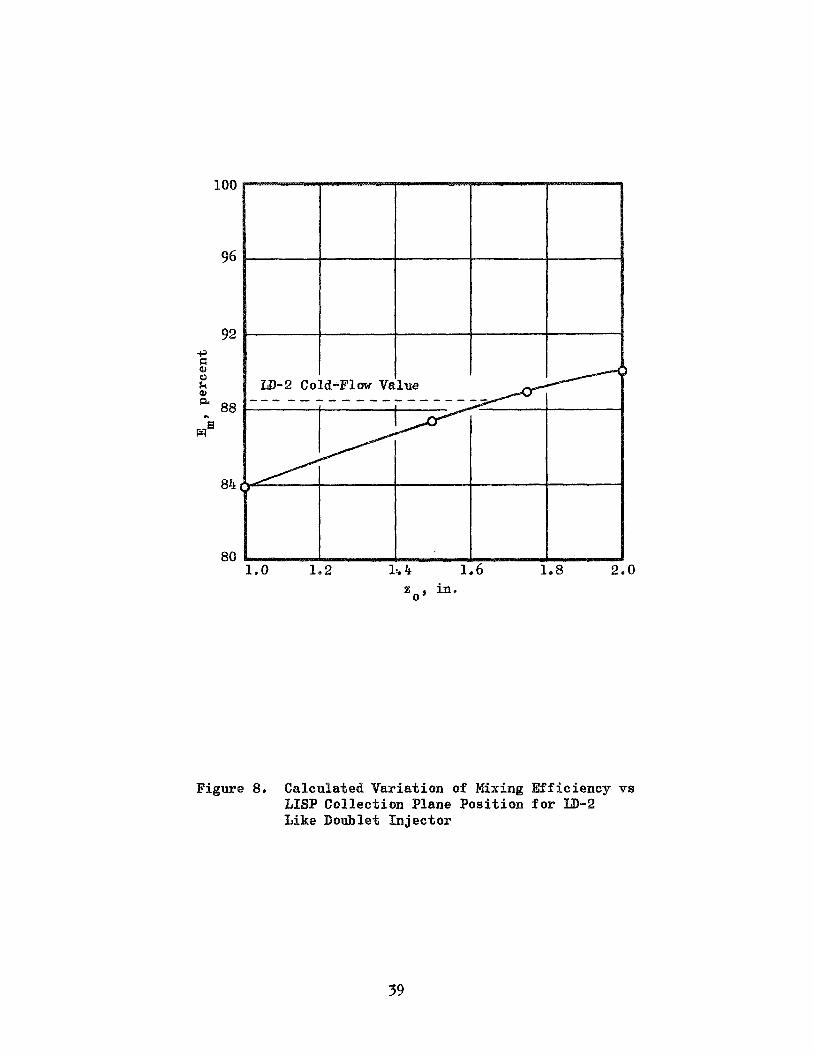
t w o empir ica l adjustments were made t o f o r c e t h e DER p red ic t ion of 7 f o r t h e nominal checkout case t o agree wi th i t s experimental value.
The f i r s t of t hese w a s t o p o s i t i o n t h e STC i n i t i a l - p l a n e such t h a t t h e
va lue of E Rupe’s mixing e f f i c i e n c y f a c t o r , ca l cu la t ed by LISP matched
t h e cold-flaw experimental va lue repor ted i n Ref. 10. Computed varia-
t i o n of Em wi th zo i s shown i n Fig. 8; from which z
se lec ted .
C*
m’
= l.7O-in w a s 0
The second empir ica l adjustment concerned t h e LISP p r e d i c t i o n of mean
p rope l l an t drop s i z e s a t t h e STC i n i t i a l - p l a n e . For l ike-doublet and
l ike-double t -pa i r e lements , experimental c*-ef f ic ienc ies were cor-
r e l a t e d a n a l y t i c a l l y i n Ref. 10 by
where is a predic ted c*-eff ic iency based on cold-flow measure-
ment of spray mass and mixture r a t i o d i s t r i b u t i o n , assuming complete
evaporat ion and no f u r t h e r mixing,
evaporat ion e f f i c i e n c y , der ived from a one-dimensional combustion model
which assumes complete mixing,
c*, mix
i s a ca l cu la t ed spray and “evap
depends s t r o n g l y upon i n i t i a l - 7 evap
100
96
92 -P a a 0
2 a 88
wB
84
80
z in. 0 )
Figure 8. Calculated Variation of Mixing Efficiency vs LISP Collection Plane Position f o r
oublet Injector
39

plane drop s i z e s ,
f u e l drop diameters given by
Cor re l a t ion w a s achieved i n Ref, 10 by us ing mean
assuming t h a t t h e ox id ize r (which i s more v o l a t i l e than t h e f u e l ) has
t h e same mean drop s i z e as t h e f u e l , and empi r i ca l ly s e l e c t i n g a va lue
f o r V
wi th i t s corresponding experimental value.
f o r c C = 2 ) w a s t h e r e a f t e r assumed t o be a func t ion ( inverse v a r i a t i o n )
only of con t r ac t ion r a t i o ,
such t h a t pred ic ted vc* f o r a p a r t i c u l a r ca se w a s forced t o agree
(320 f t / s e c g
That va lue of V g
Equation 31 was used f o r both p r o p e l l a n t s , wi th t h e appropr ia te bcr/p) r a t i o , i n t h e DER ve r s ion of t h e LISP computer program. A s might be
expected, t h e mean ox id ize r d r o p l e t diameters were not ca l cu la t ed t o be
i d e n t i c a l t o t h e f u e l d r o p l e t s i z e s , a s assumed i n Ref. 10, b u t f o r most
cond i t ions were s i g n i f i c a e t l y smaller . DER predic ted e f f i c i e n c i e s us ing
V = 320 f t / s e c were t h u s s u b s t a n t i a l l y h igher than t h e experimental
values , Therefore , V was aga in empi r i ca l ly ad jus t ed f o r t h e checkout
case u n t i l agreement wi th the experimental ‘Q w a s achieved. The
der ived va lue (190 f t / s e c f o r c c = 2) w a s then used t o p r e d i c t ‘l)
f o r a s e r i e s of o ther cases .
g
g C*
C*
Resu l t s of t h e s e c a l c u l a t i o n s a r e given i n Table 1 and shown g r a p h i c a l l y
i n Fig. 9. Design da t a f o r t h e t h r e e l ike-double t p a i r i n j e c t o r s con-
s idered a r e l i s t e d i n Table 2, The predic ted va lues of c*-eff ic iency
were seen t o agree q u i t e w e l l wi th t h e corresponding experimental va lues
except f o r t h e one case i n which t h e chamber con t r ac t ion r a t i o w a s
doubled, In t h a t c a s e , t o o coarse ox id ize r a tomiza t ion , r e s u l t i n g from
a small va lue of I V -V.\ i n Eq. 31, produced u n r e a l i s t i c a l l y low
ox id ize r evaporat ion e f f i c i ency . g J
The combustion a n a l y s i s of Ref. 10 w a s reviewed and compared wi th STC
a n a l y s i s t o determine whether some d i f f e r e n c e o the r t han t h e t rea tment
40

% F a
41
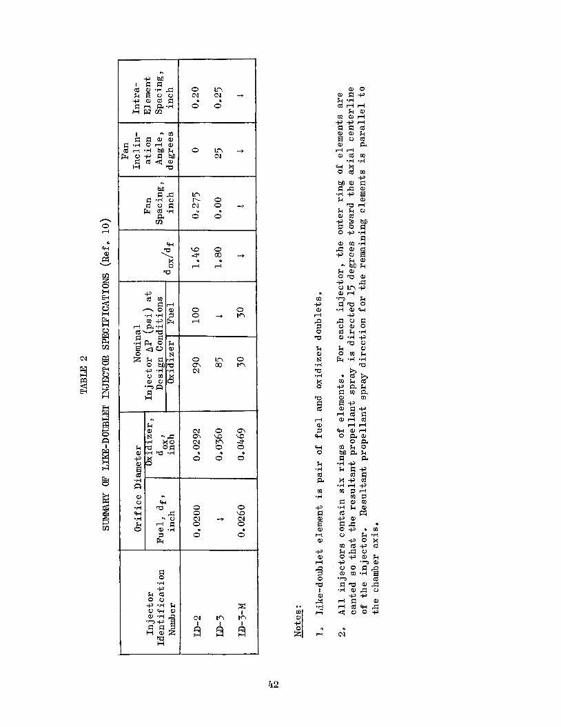
N
Y 3 E-c
cn
5 0 Tu
n
k Y N " 0
wo 2 ,..a 9
a 0 '4
o m
0 0 2 2 -
o n 4 N
m b o N O - ,
c 0 0
c o o . ; P O I ) - ,
d r l . 0
0 0 O + M rl
o n 0 m m n N
m o m m c o c o a n a 0 0 0
e 4 c)
0 0 0
0 0 0 a N 4 m 0 0
0 0 .
22 I m m m
. m -P a d s 0 5
k a N .d 5 *d x 0
'CI
zi rl a 3 w cn 0
k -4 cd a rn
*A
-P
3 !!? rl a,
-P a rl s 0 5 I a 3
rl
42
0 a m .d

100
95
+ 0 a c)
a 5 a + 0 .rl a
$ 9 n
4 - 85 5 F
80
0
90 95 100
Tc*, Actual percent
Figure 9. Comparison of Predicted and Actual C* E f f i c i e n c i e s f o r Ver i f i ca t ion Test Cases of Table 1

of o x i d i z e r mean drops ize might account f o r t h e l a r g e d i s p a r i t y i n
der ived v a l u e s of V e It was concluded t h a t t h e r e may be minor compu-
t a t i o n a l d i f f e r e n c e s , bo th i n t h e v a l u e s of evaporat ion c o e f f i c i e n t s
and i n t h e t rea tment of d r o p l e t d r a g and evaporat ion, b u t t h a t t h e major
d i f f e r e n c e was i n t h e methods used f o r d i s t r i b u t i n g a p r o p e l l a n t ' s f low
r a t e i n t o a number of d r o p l e t s i z e groups. I n Ref. 10, t e n s i z e groups
with equal flow r a t e were formed and group diameters d i s t r i b u t e d
according t o empir ica l d a t a from "cold-flow" l ike-doublet i n j e c t i o n of
molten wax (Ref. 7).
had been d i s t r i b u t e d according t o t h e Nukiyama-Tanasawa d i s t r i b u t i o n
func t ion among s i x , equally-spaced d r o p l e t s i z e groups.
g
I n t h e foregoing DE% a n a l y s i s , spray flow ra tes
Applying t h e former spray mass d i s t r i b u t i o n t o DEEI's s i x spray s i z e
groups permit ted a h igher va lue of V t o be used than b e f o r e , b u t a
va lue of V
s u b s t a n t i a l l y below t h e 320 f t / s e c level.
r e l a t i n g e C = 4 d a t a was expected, t h e r e f o r e .
s e v e r a l of t h e c a s e s i n Table 1, however, expected e f f i c i e n c i e s were
estimated by comparing predic ted case d r o p l e t s i z e s wi th those s i z e s
which gave t h e Table 1 r e s u l t s . This approach s t rengthened confidence
i n t h e a b i l i t y of STC t o p r e d i c t c = 2 r e s u l t s , b u t ind ica ted t h a t
performance of t h e c C = 4 case would s t i l l be underpredicted by about
4 o r 5 percent .
g = 240 f t / s e c der ived by analyzing two G g C
= 2 cases w a s s t i l l
Continued d i f f i c u l t y i n cor-
Rather than r e c a l c u l a t i n g
C
The DER c*-efficiency p r e d i c t i o n f o r t h e c c = 4 case w a s f i n a l l y forced
t o match t h e experimental va lue by a l t e r i n g Eq. 31 f o r drop s i z e pre-
d i c t i o n , s o t h a t it i s c o n t r a c t i o n r a t i o dependent. Simultaneously, t h e
mean diameter c a l c u l a t e d w a s changed from D t o t h e mass median
diameter 6 , which is t h e mean s i z e used i n t h e empir ica l mass d i s t r i b u - 30
t i o n expression.
from t h e wax cold-flaw r e s u l t s . Denoting [$Jo/P) p r o p / ~ g ] 'I4 as C
The r e l a t i o n s h i p 5 = 1.524 D w a s adopted d i r e c t l y
P r
30
240 i s r ea l ly 480/cc f o r c C = 2 g ives :
-1 480
112
C C +
44

where an empi r i ca l func t ion f ( e ) has been a r b i t r a r i l y placed i n t h e
second term on t h e r i g h t ,
requi red :
C
To f i t t h e e c = 4 case and t o have f (2) = 1
The e C = 4 case w a s run wi th Eq. 32 and 33 programmed i n LISP; t h e
p red ic t ed TC+ = 92*53$ compared favorably wi th t h e experimental
qc* = 9 3 4 .
S p e c i f i c Impulse
model c a l c u l a t i o n s were made f o r only one of t h e cases
l i s t e d i n Table 1, The condi t ions f o r t h i s s e l e c t e d case were t h e
i n j e c t o r a t 100 p s i a chamber p re s su re and 5019 mixture r a t i o i n a 15-in L*, 2,0 con t rac t ion r a t i o chamber,
The coord ina tes of d iv id ing s t r eaml ines and s e l e c t e d le f t - running-
c h a r a c t e r i s t i c s ca l cu la t ed by TDK a r e p l o t t e d i n Fig. 10.
This case had been processes through LISP and STC wi th an equiva len t V g
of 250 f t / s e c ( r a t h e r than t h e p re fe r r ed 240 f t / s e c ) ; as a r e s u l t , d rop
s i z e s were s l i g h t l y small and t h e STC calculated ?lC* w a s 90,71 percen t ,
about 0,9 percent h ighe r than t h e experimental va lue of 89.8 percent .
program block g ives pr inted-out s o l u t i o n s f o r c*, I
p r e d i c t i o n of c* e f f i c i e n c y w a s 2.2 percent h igher t han t h e
and CFe S
experimental value, The p red ic t ion of vacuum s p e c i f i c impulse w a s
Is = 276.04 lbf-sec/ lbm compared wi th an experimental va lue , co r rec t ed
t o vacuum condi t ions of 269,5 lbf-sec/lbm; t h i s d i f f e r e n c e is 2.4
percent of t h e experimental value,
In eva lua t ing t h e s e r e s u l t s , it must be recognized t h a t it i s d i f f i c u l t
t o draw genera l conclusions from one t e s t ,
t h e r e f o r e , must be r e rded as t e n t a t i v e and somewhat specu la t ive ,
The fo l lowing d i s c u s s i o n ,
45

&
rl
0
rl
co 0
W 0
& hl
0 0 9
0
0 rl
46

This would be equa l ly t r u e even i f t h e pred ic ted performance f i g u r e s
had matched t h e experimental va lues p r e c i s e l y ,
The vacuum t h r u s t va lues i n Ref, 10 had been co r rec t ed by 1.0 percent
f o r combustor and nozzle hea t t r a n s f e r losses .
cu l a t ed boundary layer l o s s e s f o r o the r combustors and cond i t ions , it was i n f e r r e d t h a t t h e l o s s f o r t h i s case should be about one percent ,
The impl i ca t ion i s t h a t both t h e p red ic t ed and experimental s p e c i f i c
impulses should be lowered by about t h e same amount i n account ing f o r
boundary layer l o s s e s , i . e e , e s s e n t i a l l y none of t h e 2,4 percent
dev ia t ion can be a t t r i b u t e d t o boundary l a y e r losses .
By examination of c a l -
Poss ib ly a s t rong c o n t r i b u t o r t o t h e dev ia t ions i n both c* and Is i s
t h e d i s c o n t i n u i t y a t t h e TDK i n i t i a l - l i n e which is a r e s u l t of changing
t h e r e from STC's f r o z e n , i s e n t r o p i c l o c a l expansion (from t h e e q u i l i -
brium s t agna t ion temperature corresponding t o t h e l o c a l gas mixture
r a t i o ) t o a t r u e equi l ibr ium solu- t ion a t t h e i n i t i a l l i n e , For t h e
cu r ren t v e r i f i c a t i o n case , t h e magnitude of t h e d i s c o n t i n u i t y w a s q u i t e
s i g n i f i c a n t : t h e equ i l ib r ium s t a t i c temperatures and molecular weights
a t t h e i n i t i a l l i n e were about 11 percent and 3 percent h ighe r ,
r e s p e c t i v e l y , than t h e corresponding STC computed values. With t h e
i n i t i a l l i n e va lues of pressure and s t ream tube a r e a s and gas v e l o c i t i e s
assumed t o be i n v a r i a n t ac ross t h e i n i t i a l l i n e , t h e s e combine t o
produce d iscont inuous drops of about 8 percent i n s t ream tube gas
d e n s i t i e s and gas f l awra te s , This i s s u b s t a n t i a l l y l a r g e r t han t h e
modest d i s c o n t i n u i t i e s t h a t were a n t i c i p a t e d and were expected t o have
only s l i g h t e f f e c t s on p red ic t ion accuracy. Considering t h e equ i l ib r ium
values t o be t h e c o r r e c t ones, t h e imp l i ca t ion is t h a t t h e p re s su re
l e v e l f o r t h e e n t i r e STC a n a l y s i s , inc luding t h e i n i t i a l - l i n e , i s
t o o low. This w i l l n o t only a f f e c t t h e va lues of t h e i n i t i a l l i n e
i n t e g r a l s upon which T K ' s computation of c* and t h r u s t a r e based b u t
may change t h e spray vapor i za t ion e f f i c i e n c y as we l l , I n t e r e s t i n g l y ,
t h e s e e f f e c t s should cause t h e c* and
comparable magnitudes, as w a s observedD
p r e d i c t i o n s t o d e v i a t e by
47

(Correct ion of t h e TDK i n i t i a l - l i n e d i s c o n t i n u i t y i d e a l l y would involve
us ing l o c a l equi l ibr ium s o l u t i o n s throughout t h e STC program analys is .
That would r e q u i r e a moderate amount of reprogramming and checkout b u t ,
more impor tan t ly , STC computation t imes would be d ra s t i ca l ly increased,
Before going t o t h a t extreme, some a l t e r n a t i v e approaches should be
examined. One such a l t e r n a t i v e i s simply r e p l a c i n g t h e f rozen v a l u e s
of y(c i ) i n t h e combustion gas p r o p e r t i e s t ab le wi th t h e s h i f t i n g
values . A cursory examination of t h e c u r r e n t ca se suggests t h a t t h e
temperature d i s c o n t i n u i t y might be reduced t o 2 t o 3 percent by t h i s
approach. )
48
CoNCLUSIoNS
1, A s e r i e s of e x i s t i n g computer programs has been s u c c e s s f u l l y
modified and combined i n t o a s i n g l e operable computer program t h a t
i s capable of p r e d i c t i n g l i q u i d rocke t engine performance,
The developed performance model w a s found t o be capable of p r e d i c t i n g
engine c*-ef f ic ienc ies w i t h i n approximately k 1 percent as v e r i f i e d
by comparison wi th a l imi t ed amount of l ike-double t -pa i r i n j e c t e d
BLOX/LPG p r o p e l l a n t hot-f i r i n g data.
f o r o the r p r o p e l l a n t s or i n j e c t o r s may depend upon adjustment of
empi r i ca l parameters t o f o r c e agreement wi th one or more experi-
mental d a t a po in t s .
The v a l i d i t y of t h e model 's p r e d i c t i o n s of s p e c i f i c impulse w a s
n o t as w e l l v e r i f i e d as were i ts c*-eff ic iency p red ic t ions . Some
f u r t h e r model re f inements w i l l be requi red t o achieve -I 1 percent
accuracy on Is.
depended s t r o n g l y upon v a l i d cold-flaw spray mass d i s t r i b u t i o n
and drop s i z e c o r r e l a t i o n s f o r t h e p a r t i c u l a r type of i n j e c t i o n
element under study.
2,
Achieving comparable accuracy
3,
4. Operation of t h e model, and t h e v a l i d i t y of i t s p r e d i c t i o n s ,
49/50

REC TI QNS
The fo l lowing work is recommended t o extend t h e v e r i f i e d a p p l i c a b i l i t y
of t h e developed performance a n a l y s i s model t o wider ranges of des igns ,
p r o p e l l a n t s and opera t ing condi t ions :
1.
2,
3.
4,
5.
6,
7.
8.
9. 10 e
11,
Perform a d d i t i o n a l v e r i f i c a t i o n a n a l y s i s of t h e model's c a p a b i l i t y
f o r p r e d i c t i n g s p e c i f i c impulse,
Reduce o r e l imina te t h e gas-phase p r o p e r t i e s d i s c o n t i n u i t y a t t h e
STC-TDK i n t e r f a c e .
a,
b. Use f u l l s h i f t i n g equi l ibr ium throughout STC,
Refine t h e planar- to-curved-isobar t r a n s i t i o n , r e t a i n i n g p r e c i s e
area c o n t i n u i t y t o t h e immediate neighborhood of t h e t h r o a t .
Supplement t h e t r a n s o n i c flow pressure d i s t r i b u t i o n near t h e t h r o a t
wi th a subsonic model f o r c o n i c a l o r tapered combustion chambers.
Improve t h e t rea tment of spray d rop le t vapor i za t ion , account ing f o r
d r o p l e t hea t ing and combustion a t s u p e r c r i t i c a l pressures .
Extend t h e program's c a p a b i l i t i e s t o gas / l iqu id p rope l l an t s ,
Ca lcu la t e and punch out d a t a needed f o r subsequent a n a l y s i s wi th
t h e TBL (Turbulent Boundary Layer) computer program.
Include 3D-COMBUST a n a l y s i s of t h e r a p i d combustion zone.
S impl i fy computer program input .
Improve computational e f f i c i e n c y t o reduce execut ion times.
Assemble a l ibrary of a v a i l a b l e i n j e c t o r des ign c o r r e l a t i o n s ,
Evaluate use of s h i f t i n g y i n STC computations and/or
51/52

c a - area
l o c a l sound speed
empir ica l sp ray c o e f f i c i e n t s , Eq, 2 drag c o e f f i c i e n t
approximate evaporat ion c o e f f i c i e n t
nozzle d ischarge c o e f f i c i e n t
c o e f f i c i e n t involv ing propel lan t p r o p e r t i e s , Eqe 32 mixture r a t i o
c h a r a c t e r i s t i c exhaust v e l o c i t y
t h r u s t Coef f i c i en t
s p e c i f i c heak a t cons tan t p re s su re
d r o p l e t o r l i q u i d j e t diameter
mass median d r o p l e t diameter
volume-number mean d r o p l e t diameter
Rupe mixing e f f i c i e n c y f a c t o r (Ref, 6 ) drag f o r c e
func t ion of con t r ac t ion r a t i o , Eq. 32 and 33 g r a v i t a t i o n a l c o e f f i c i e n t
s p e c i f i c impulse
h e a t of vapor i za t ion
thermal conduct iv i ty
d r o p l e t evaporat ion c o e f f i c i e n t
molecular weight
d r o p l e t mass o r spray s i z e group mass
r a t e of change of mass
drop 1 e t c onc e n t ra t i on (n o/vo 1 ume ) N = number f lowra te of d r o p l e t s
= number of i n j e c t i o n elements NEL
nt
N U = Nusse l t number
= number of s t ream tubes
P = pres su re
53

P* Re
R U
RR RT r
S
v g w
W
wool cy w
Z
Z 0
GREEK LETTERS
P
pres su re corresponding t o sonic flow
Reynolds number
un ive r sa l gas cons tan t
nozzle t h r o a t r a d i u s r a t i o (curvature/opening)
nozzle t h r o a t r a d i u s
r a d i a l coord ina te
s t ream tube path length
t emp e r a t ur e
ve 1 oc i t y
empir ica l parameter i n a tomiza t ion equat ion , Eq. 31 prope l l an t mass f l u x a t a s p a t i a l mesh po in t
p rope l l an t mass f l u x c o n t r i b u t i o n from an i n j e c t i o n element t o a mesh poin t
w ( x , y , z ) f o r x=y = 0 , z=1
t o t a l and l o c a l ( o r s t ream tube ) f lowra te s
r ec t angu la r coord ina tes ( referenced t o an i n j e c t i o n e lement ) a x i a l coord ina te
i n i t i a l plane f o r beginning spray combustion a n a l y s i s
=
=
nozzle w a l l angle (from chamber a x i s )
r a t i o of s p e c i f i c h e a t s o r a d i a b a t i c expansion c o e f f i c i e n t
= chamber con t r ac t ion r a t i o
= nozzle expansion r a t i o
= decimal t o l e r a n c e , convergence on t h r o a t a r e a
= e f f i c i e n c y f a c t o r
= angular coord ina te
= v i s c o s i t y
= d e n s i t y
= su r face t e n s i o n
54
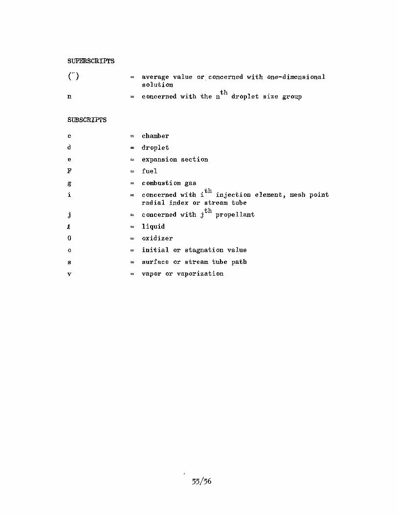
SUPERSCRIPTS
n
SUBSCRIPTS
j a 0
O
S
V
= average va lue o r concerned wi th one-dimensional s o l u t ion
concerned wi th t h e nth d r o p l e t s i z e group =
chamber
d r o p l e t
expansion s e c t i o n
f u e l
combustion gas
concerned wi th ith i n j e c t i o n element, mesh po in t r a d i a l index o r stream tube
concerned wi th jth p rope l l an t
l i q u i d
ox i d i z e r
i n i t i a l o r s t agna t ion va lue
su r face or s t ream tube pa th
vapos o r vapor iza t ion
55/56

REFERENCES
1.
e
30
4.
5,
G.
8.
90
10,
P ieper , J, L, , "ICRPG Liquid P rope l l an t Thrust Chamber Performance Evaluat ion Manual CPIA Publ, No, 178, Chemical Propuls ion Inf or- mation Agency, S i l v e r Spr ing , Md., September 1968.
Hines, W, S, , Combs, L, P a , Ford, We M., and VanWyk, R, , "Develop- ment of I n j e c t o r Chamber Compat ib i l i ty Ana lys i s , " F i n a l Report AFRPL-TR-70-12, Rocketdyne, a Div is ion of North American Rockwell Corp,, Canoga Park, C a l i f . , March 1970.
Combs, L, P, and Chadwick, W, D e , "Liquid Rocket Performance Computer Model w i th D i s t r i b u t e d Energy Release , Computer Program Documentation , I 1 Rocketdyne a Div is ion of North American Rockwell Corporat ion, Canoga Park, Ca l i f e , September 1970.
Su t ton , R, D o , Hines , Wa S., and Combs, L. P,, "Comprehensive Analys is of Liquid Rocket Combustion,'' AIAA Paper No. 70-622, June 1970.
K l i e g e l , J, R e , e t al , "ICRPG Two-Dimensional K ine t i c Reference Program," Dynamic Science, a Div is ion of Marshal l I n d u s t r i e s , I m i n e , Ca l i f . , J u l y 1968.
Rupe, J, H, and J a i v i n , Go H,, "The E f f e c t s of I n j e c t i o n Mass Flux D i s t r i b u t i o n s and Resonant Combustion on Local Heat Transfer i n a Liquid P rope l l an t Rocket Engine,'f B o g , Rpt. 32-648, J e t Propuls ion Laboratory, Pasadena, Cal i f * , October 1964,
Dickerson, R, A , , Ta t e , K. and B a r s i c , N e , "Corre la t ion of Spray I n j e c t o r Parameters wi th Rocket Engine Performance , I 1 F i n a l Repor t , AFRPL-TR-68-147, Rocketdyne , a Div is ion of North American Rockwell Corporat ion, Canoga Park , Calif . , June 1968
Nickerson, G, R e , " I n s t r u c t i o n s f o r Replacing t h e Transonic Analys is of t h e TDK Computer Program," Dynamic Science L e t t e r Repor t , received A p r i l 1970.
K l i e g e l , J, Re and Levine, J, N e , "Transonic Flaw i n Small Throat Radius of Curvature Nozzles," AIAA Journa l , Vo l , 7 , No. 7 , July 1969.
F a l k , A, Ye, Clapp, S, D, and Nagai, C, K,, "Space S to rab le Propel- l a n t Performance Study," F i n a l Report , NASA CR-72487, Rocketdyne, a Div i s ion of North American Rockwell Corpora t ion , Canoga Park, Ca l i f . , November 1968,
57/58

A MA
D i s t r i b u t i o n L i s t f o r F i n a l Report NASA CR- "Liquid Rocket Performance Computer Model
NAS7-746 Rocketdyne Div i s ion
North American Rockwell Corporat ion
i s t r i b u t e d Energy Release"
Nat ional Aeronau.tics and Space Adminis t ra t ion Washington, D, C, 20546 At ten t ion : Cont rac t ing Of f i ce r
Pa ten t Off i c e
Nat ional Aeronaut ics and Space Adminis t ra t ion Lewis Research Center 21000 Brookpark Road Cleveland, Ohio 44135 At ten t ion : Off i c e of Technical Information
D r , R, J, Priem Larry Gordon E, W, Conrad Sanford Gordon
Nat ional Aeronaut ics and Space Adminis t ra t ion Manned Spacecraf t Center Houston, Texas 77001 At t en t ion : Off ice of Technical Information
J, G, Thibodaw, Jr, Ronald C. Kahl
Nat iona l Aeronaut ics and ace Adminis t ra t ion Marshall Space F l i g h t Center Hun t sv i l l e Alabama 35812 At t en t ion : Technical Library
Dale Burrows, §&E - ASTN - PJ, Bldg, 4666
COPIES
1 1
1 1 1
1 1
Nat iona l Aeronaut ics and Space Adminis t ra t ion Ames Research Center Moffatt F i e l d , C a l i f o r n i a 94035 At t en t ion : Cont rac t ing Offic Cont rac ts Sec t ion (ASCR) 1
Mission Analys is 1 Albe r t a Alksne N-203-9 1
A- 1

COPIES
J e t Pr opul s i on Lab o r a t ory 4800 O a k Grove Drive Pasadena, C a l i f o r n i a 91103 At t en t ion : Jack H. Rupe
Henry Burlage, J re , Propuls ion Div. 38 Walter Be Powell
Nat ional Aeronaut ics and Space Adminis t ra t ion Washington, D e C a 20546 At t en t ion : Chief , Liquid Propuls ion Technology RPL
Off ice of Advanced Research and Technology Di rec to r Technology U t i l i z a t i o n Div is ion
Off ice of Technology U t i l i z a t i o n D i r e c t o r , Launch Vehic les and Propuls ion, SV
Office of Space Science and Appl ica t ions D i r e c t o r , advanced Manned Missions, MT
Off ice of Manned Space F l i g h t
Nat ional Aeronaut ics and Space Adminis t ra t ion
College Park , Maryland 20740 At t en t ion : S c i e n t i f i c and Technical Information F a c i l i t y
P-0, BOX 33
Langley Research Center Langley S t a t i o n Hampton, V i r g i n i a 23365 At t en t ion : Ed Cortwright , D i r e c t o r
Lewis Research Center 21000 Brookpark Road Cleveland, Ohio 44135 At t en t ion : D r , Abe S i l v e r s t e i n , D i rec to r
Nat iona l Aeronaut ics and Space Adminis t ra t ion John F. Kennedy Space Center Cocoa Beach, F l o r i d a 32931 At t en t ion : D r . K u r t H. Debus
Aeronaut ica l Systems Divis ion A i r Force Systems Command Wright-Pat terson A i r Force Base Dayton, Ohio 45433 At t en t ion : D, L, Schmidt, Code ASRCNC-2
Arnold Engineering Development Center Arnold A i r Force S t a t i o n Tullahoma, Tennessee 37388 At t en t ion : D r , H, K, Doetsch
2 2 1
25
2
2
2
A-2

Bureau of Naval Weapons epartment of t h e Navy ash ington , D, 6, 20546
At t en t ion : J, Kay, RTm-41
Defense Documentation Center Headquarters Cameron S t a t i o n , Bui ld ing 5 5010 Duke S t r e e t Alexandria , V i r g i n i a 22314 At ten t ion : TISIA
1
1
Pica t inny Arsenal Dover, New Jersey 07801 At t en t ion : I, F o r s t e n , Chief Liquid Propu.lsion Laboratory 1
A i r Force Rocket Propuls ion Laboratory Research and Technology Divis ion A i r Force Systems Command Edwards, C a l i f o r n i a 93523 At t en t ion : RmcpD/Mr. H. Main
W R R C / W ~ ~ ~ ~ C, R i t a Thomas J, F a n c i u l l o
U, $3, Army Miss i l e Command Redstone Arsena l , Alabama 35809 At t en t ion : Mr, Walter Wharton
U, 5, Bureau of Mines 4800 Forbes Avenue P i t t sbu rgh Pennsylvania 15213 At ten t ion : Mr, Henry Pe r l ee
U, S, Naval Ordnance Test S t a t i o n China Lake, C a l i f o r n i a 93557 A t t e n t i on : s Cou.Ch
A i r Force Q f f i c e of S c i e n t i f i c Research
Ar l ing ton V i r g i n i a 22209 At t en t ion : B, T, Wolfson
i 1 s on B ou.1 evar d
Chemical Propuls ion Information Agency s i c s Laboratory
At t en t ion : Tom Reedy
1 1 1
1
1
1
A-3
C QPIES
Aeroje t Liqui’d Rocket Company Sacramento, C a l i f o r n i a At t en t ion : Jack I t o
D, Le Kors
Aero j e t - Genera 1 C orp o r a t i on P,O, Box 296 Azusa, C a l i f o r n i a 91703 At ten t ion : W, L, Rogers
Space Div is ion Aerojet-General Corporation 9200 East F l a i r Drive E l Monte, C a l i f o r n i a 91734 At ten t ion : S, Machlawski
Aerospace Corporation 2400 East E l Segund o Boulevard P,O. Box 95085 Los Angeles, C a l i f o r n i a 90045 At ten t ion : 0. W, Dykema
W, B. Roessler
A t l a n t i c Research Corporation Edsa l l Road and S h i r l e y Highway Alexandria , V i rg in i a 22314 At t en t ion : Libra r i an
B e l l Aerosystems Company P,Q, Box 1 Buffa lo , New York 14240 At ten t ion : W, M. Smith
Boeing Company P.0, Box 3707 S e a t t l e , Washington 98124 At t en t ion : J. De Alexander
Wright Aeronaut ical Divis ion C u r t i ss-Wr i g h t Corporation Woodridge, New Je r sey 07075 At t en t ion : G, Kel ley
Dynamic Science Div is ion Mars ha1 1 Indu s t r i e s I r v i n e , C a l i f o r n i a At ten t ion : G, Nickerson
T, Kosvic
1 1
1
1
1 1
I
1
1
1 1
A- 4
C
Research Center F a i r c h i l d H i l l e r Corporat ion Germant own Maryland At t en t ion : Ralph H a l l
Missile and Space Systems Center General E l e c t r i c Company 'Valley Forge Space Technology Center
Ph i l ade lph ia , Pennsylvania At t en t ion : F, Mezger
F, E, Schul tz
PeQ, Box 8555
Gurmman A i r c r a f t Engineering Corporat ion Bethpage, Long I s l and New York 11714 At t en t ion : Joseph Gavin
Honeywell, Inc. Aerospace Div is ion 2600 Ridgeway Road Minneapolis, Minnesota At t en t ion : Mr, Gordon Harms
Hughes A i r c r a f t Company Aerospace Group C e n t i n e l l a and Teale S t r e e t s Culver City, C a l i f o r n i a 90230 At t en t ion : E, H, Meier, V,P, and Divi ion Man ger 9
Research and Development Div i s ion
Ar thur D, L i t t l e , Inc, 20 Acorn Park Cambridge, Massachusetts 02140 A t t e n t i on :
Loc kheed Br opu 1s i on C ompany P,Q, Box 111 Redlands, C a l i f o r n i a 92774 At t en t ion : He k, Thackwell
The h r q u a r d t Corporat ion 16555 Sa t i coy S t r e e t Van Nuys, C a l i f o r n i a 91409 At t en t ion : Howard
1
1 1
1
1
1
1
1
1

COPIES
Denver Div is ion Martin Marietta Corporation P,O, Box 179 Denver, Colorado 80201 A t t e n t i on : D r e Morgan t h a l e r
A, J. Kul las W i l l i a m S c o t t
Astropower Laboratory Newport Beach , C a l i f o r n i a 92663 At ten t ion : Dr . George Moc
M i s s i l e and Space Systems Divis ion McDonnell-Douglas Ai rcraf t Company 3000 Ocean Park Boulevard Santa Monica, C a l i f o r n i a 90406 A t t e n t i o n : Mr. R, W. H a l l e t , Chief Engineer
Advanced Space Technology
Space and Information Systems Divis ion North American Rockwell Corporation 12214 Lakewood Boulevard Downey, C a l i f o r n i a 90241 A t t e n t i o n : Library
Northrop Space Labora tor ies 3401 West Broadway Hawthorne, C a l i f o r n i a 90250 At ten t ion : Dr , W i l l i a m Howard
F l o r i d a Research and Development Center Pratt and Whitney A i r c r a f t Corporat ion West Palm Beach , F l o r i d a At ten t ion : Robert C a r r o l l
B. D, Powell
Stanford Research I n s t i t u t e
Menlo Park, C a l i f o r n i a 94025 At ten t ion : D r , Gerald Marxman
TRW Systems Group TRS? Incorporated One Space Park Red ondo Beach, C a l i f o r n i a 90278 A t t e n t i o n : S, S, Cherry
1 1 1
1
1
1
1
1 1
1
1
A- 6
Denv i l l e , Ne At t en t ion : i g h t S, Smith
Research Labora tor ies 400 Main S t r e e t East Har t fo rd , Connecticut 06108 At ten t ion : & l e Martin
United Technology Center 587 Methilda Avenue P,O, Box 358 Sunnyvale, C a l i f o r n i a 94088 At ten t ion : D r , David Altman
Unive r s i ty of Michigan Aerospace Engineering Ann Arbor, Michigan 48104 At t en t ion : J, A, Nichol l s
Univers i ty of C a l i f o r n i a Department of Chemical Engineering 6161 Etcheverry H a l l Berkeley, C a l i f o r n i a 94720 At t en t ion : A, K, Oppenhiem
R, Sawyer
Purdue Univers i ty School of Mechanical Engineering La faye t t e , Indiana 47907 At t en t ion : J, Ea, Osborn
Sacramento, S t a t e College
60000 J, S t r e e t Sacramento, C a l i f o r n i a 95819 At t en t ion : E, He Reardon
I l l i n o i s I n s t i t u t e of Technology
At t en t ion : T, P, Torda
1
1
1
1
1 1
1
1
a
A-7

COPIES
Polytechnic I n s t i t u t e of B r o o k l y n Graduate Center Route 110 Farmingdale , New Y o r k A t t en t ion : V, D, Agusta
Georgia I n s t i t u t e of Technology A t l a n t a , Georgia 30332 At t en t ion : B, T, Zinn
Univers i ty of Denver Re search I n s t i t u t e Denver, Colorado At ten t ion : W, H, McLain
New Y o r k Univers i ty Department of Chemical Engineering Univers i ty Heights New Y o r k 53, New York At t en t ion : Leonard Dauerman
The Johns Hopkins Un ive r s i ty Applied physics Laboratory 8621 Georgia Avenue S i l v e r Spr ings , Maryland 20910 At t en t ion : W, G, B e r l
Pr ince ton Univers i ty F o r r e s t a l Campus Guggenheim Labora tor ies Pr ince ton , New J e r s e y 08540 At t en t ion : I. Glassman
The Univers i ty of Shef f i e l d Department of Fuel Technology St . George's Square S h e f f i e l d 1, Yorks, England At ten t ion : M r , J, Swithenbank
Mot orear Enst i t u s u Professor Zubeyir Demirgue Di rec to r of Engine I n s t i t u t e I s t anbu l - Gumussuyu
I n s t i t u t o Nacional De Tecnica Aerospacial Carlos Sanchez-Tarifa Serrano 43 Madrid, Spain
1
1
1
1
1
1
1
1
A - 8