Embed Size (px)
Citation preview
Interference
See Chapter 9 of Hecht
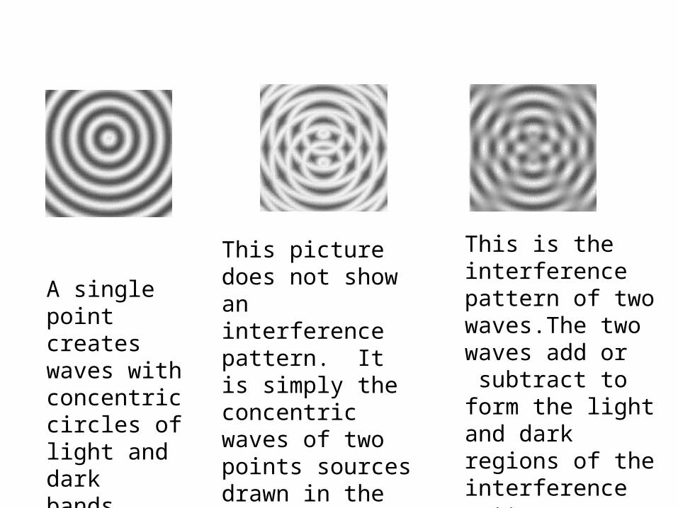
A single point createswaves with concentriccircles of light and dark bands.
This picture does not show an interference pattern. It is simply the concentric waves of two points sources drawn in the same plane. Contrastthis with the image to the right
This is the interference pattern of two waves.The two waves add or subtract to form the light and dark regions of the interference pattern
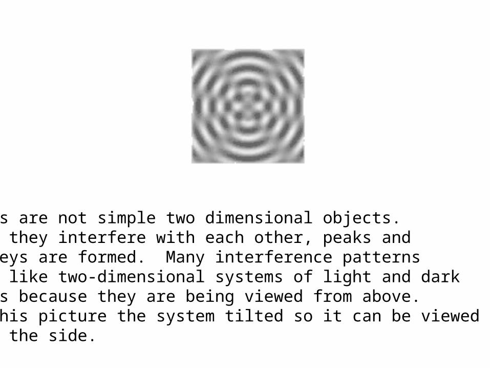
Waves are not simple two dimensional objects. When they interfere with each other, peaks andvalleys are formed. Many interference patternslook like two-dimensional systems of light and darkbands because they are being viewed from above. In this picture the system tilted so it can be viewedfrom the side.
E1
E2
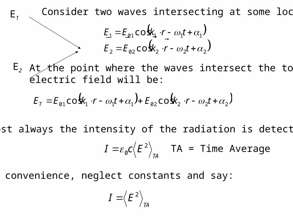
Consider two waves intersecting at some location
222022
111011
cos
cos
trkEE
trkEE
At the point where the waves intersect the totalelectric field will be:
2220211101 coscos trkEtrkEET
Almost always the intensity of the radiation is detected
TAEcI 2
0
TA = Time Average
For convenience, neglect constants and say:
TAEI 2
1221
212
22
12 2
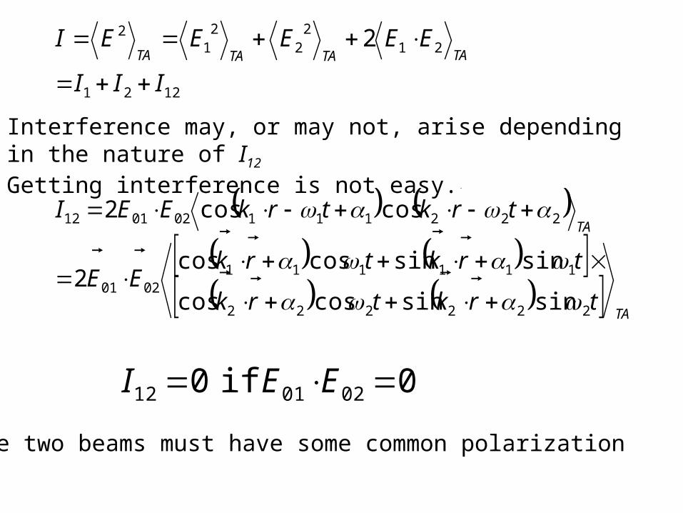
III
EEEEEITATATATA
Interference may, or may not, arise depending in the nature of I12 Getting interference is not easy.
TA
TA
trktrk
trktrkEE
trktrkEEI
222222
1111110201
222111020112
sinsincoscos
sinsincoscos2
coscos2
0 if 0 020112 EEI
The two beams must have some common polarization
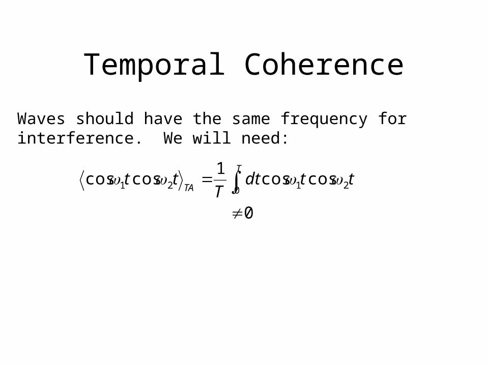
Temporal Coherence
Waves should have the same frequency for interference. We will need:
0
coscos1
coscos0 2121
T
TAttdt
Ttt
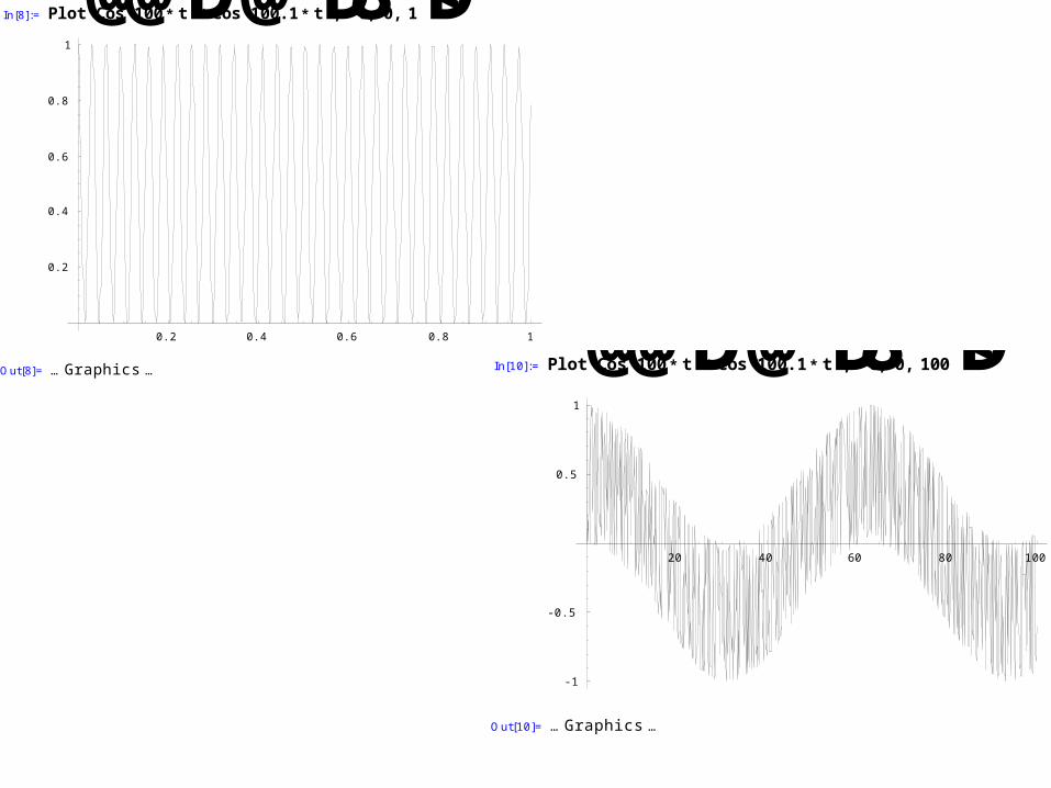
In[8]:= Plot@Cos@100* tD* [email protected]* tD,8t, 0, 1<D
0.2 0.4 0.6 0.8 1
0.2
0.4
0.6
0.8
1
Out[8]= … Graphics … In[10]:= Plot@Cos@100* tD* [email protected]* tD,8t, 0, 100<D
20 40 60 80 100
-1
-0.5
0.5
1
Out[10]= … Graphics …
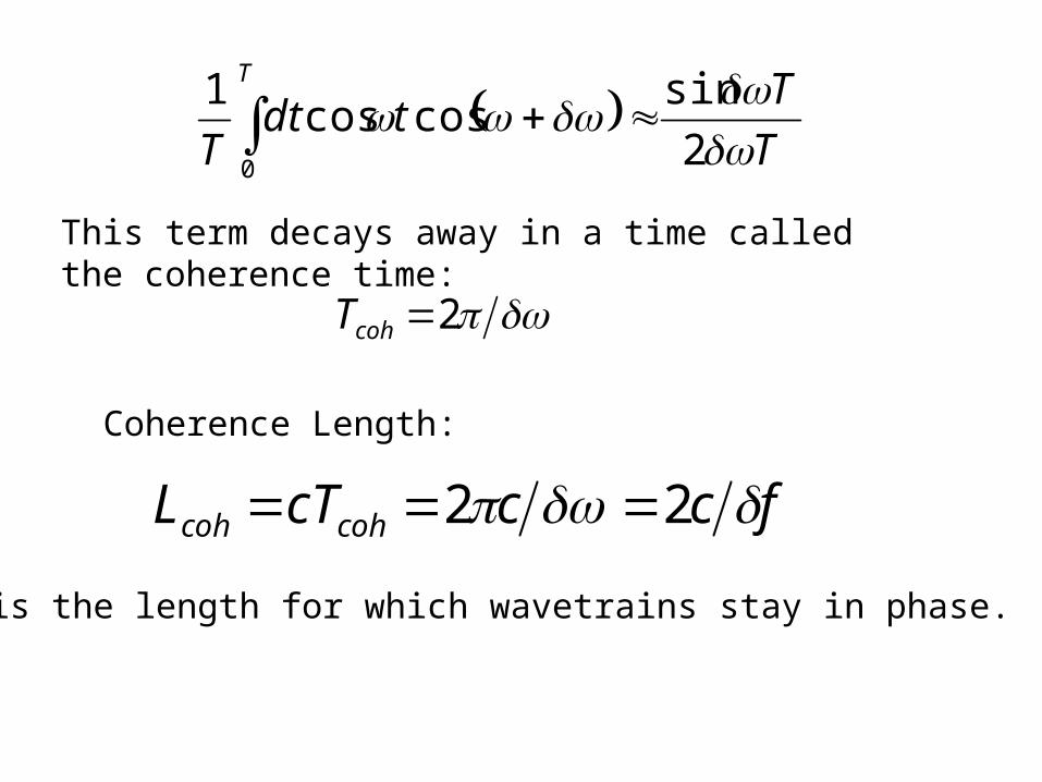
T
Ttdt
T
T
2
sincoscos
1
0
This term decays away in a time called the coherence time:
2cohT
Coherence Length:
fcccTL cohcoh 22
This is the length for which wavetrains stay in phase.
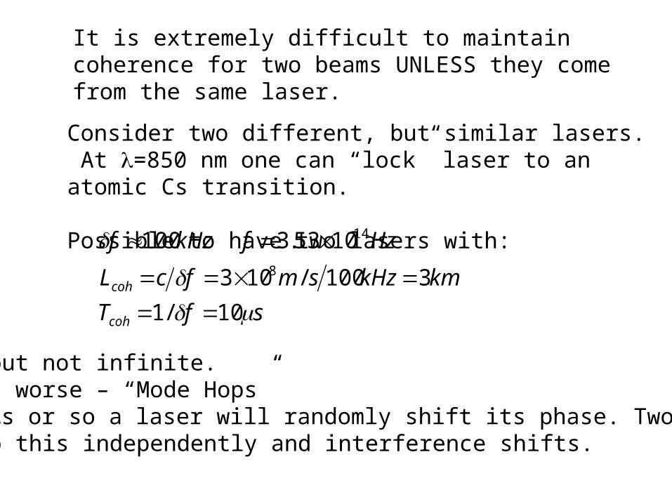
It is extremely difficult to maintain coherence for two beams UNLESS they come from the same laser.
Consider two different, but similar lasers. At =850 nm one can “lock” laser to an atomic Cs transition.
Possible to have two lasers with:
sfT
kmkHzsmfcL
HzfkHzf
coh
coh
10/1
3100/103
1053.31008
14
Long, but not infinite. What is worse – “Mode Hops”Every s or so a laser will randomly shift its phase. Two laserswill do this independently and interference shifts.
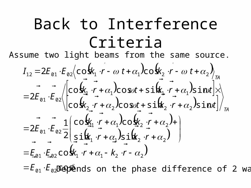
Back to Interference CriteriaAssume two light beams from the same source.
cos
cos
sinsin
coscos
2
12
sinsincoscos
sinsincoscos2
coscos2
0201
22110201
2211
22110201
2222
11110201
2211020112
EE
rkrkEE
rkrk
rkrkEE
trktrk
trktrkEE
trktrkEEI
TA
TA
Depends on the phase difference of 2 waves
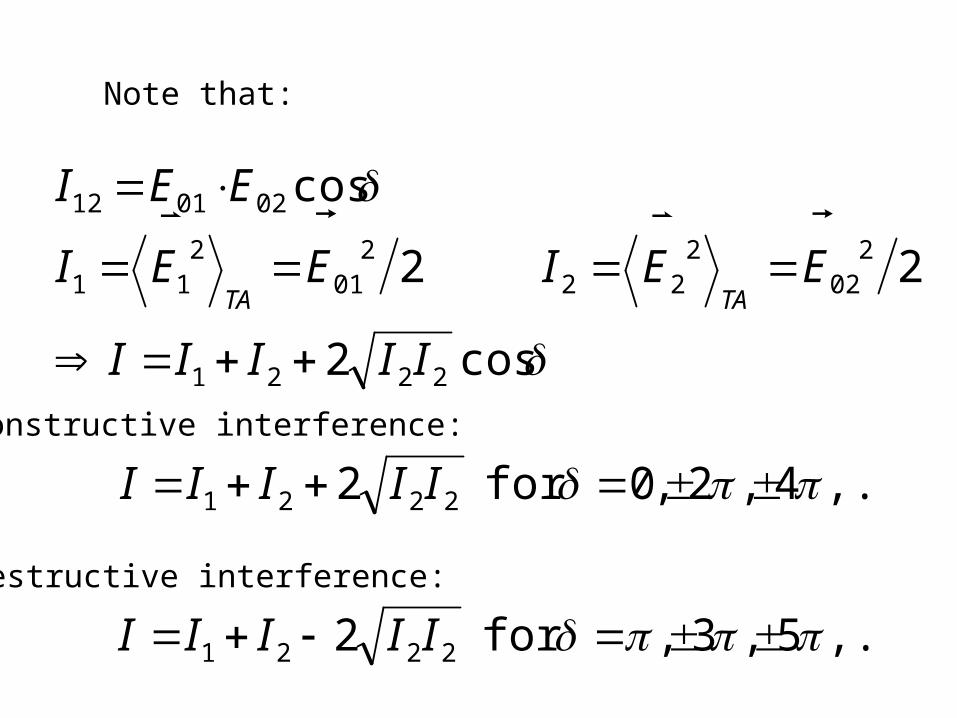
Note that:
cos2
22
cos
2221
202
222
201
211
020112
IIIII
EEIEEI
EEI
TATA
Constructive interference:
,...4,2,0for 2 2221 IIIII
Destructive interference:
,...5,3,for 2 2221 IIIII
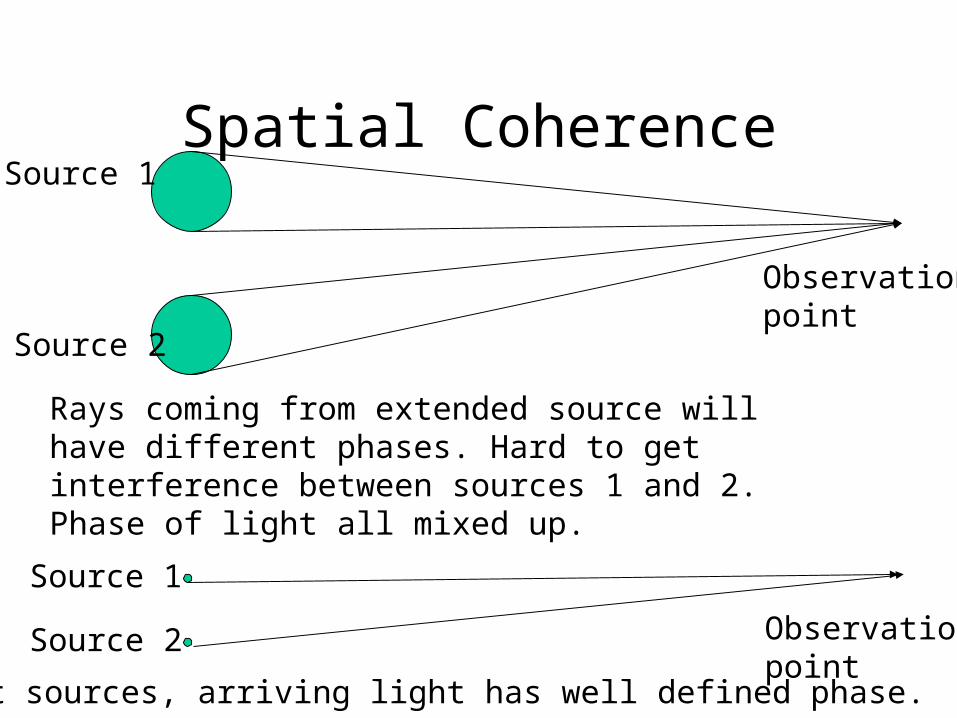
Spatial CoherenceSource 1
Source 2
Observationpoint
Rays coming from extended source will have different phases. Hard to get interference between sources 1 and 2. Phase of light all mixed up.
Source 1
Source 2 Observationpoint
For point sources, arriving light has well defined phase.
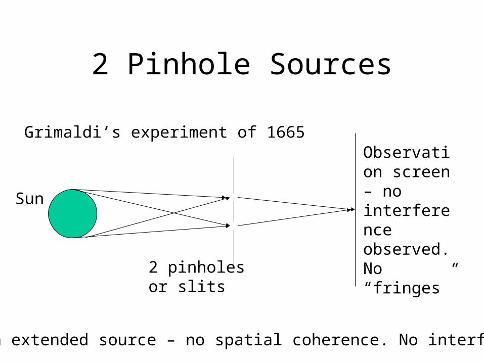
2 Pinhole Sources
Grimaldi’s experiment of 1665Observation screen – no interference observed. No “fringes”
Sun
Sun is an extended source – no spatial coherence. No interference
2 pinholes or slits
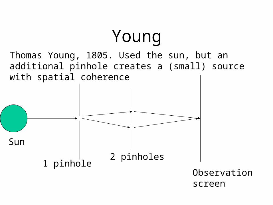
YoungThomas Young, 1805. Used the sun, but an additional pinhole creates a (small) source with spatial coherence
Sun
1 pinhole2 pinholes
Observationscreen
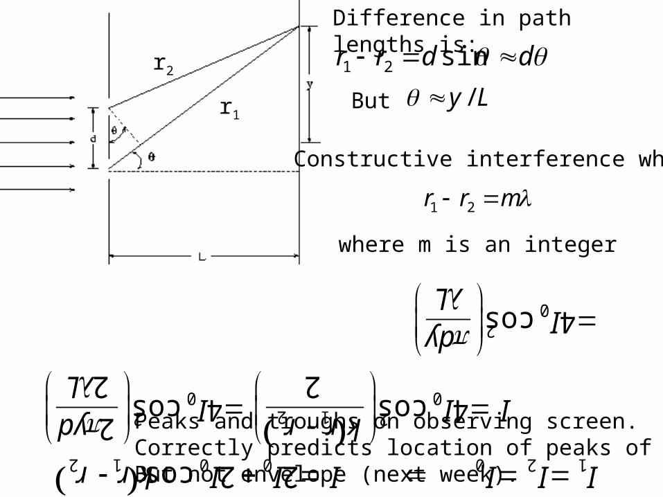
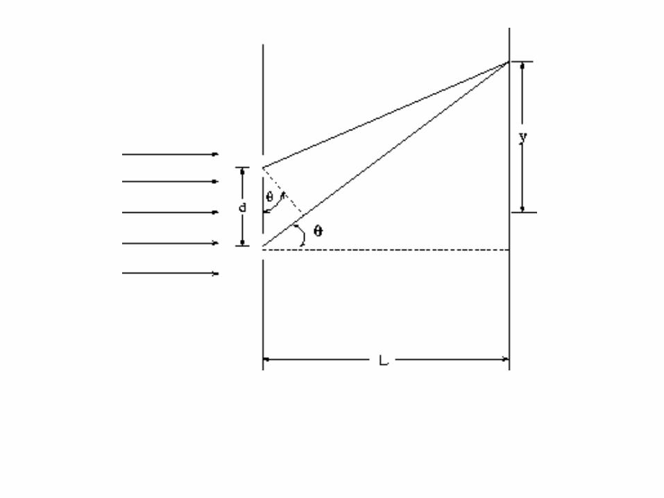
Difference in path lengths is:
r1
r2 ddrr sin21
But Ly /
Constructive interference when
mrr 21
where m is an integer
L
dyI
L
ydI
r r kI I
r r k I I I I I I
20
20
2 1 20
2 1 0 0 0 2 1
cos 4
2
2cos 4
2cos 4
cos 2 2
Peaks and troughs on observing screen. Correctly predicts location of peaks of troughs,But not envelope (next week).
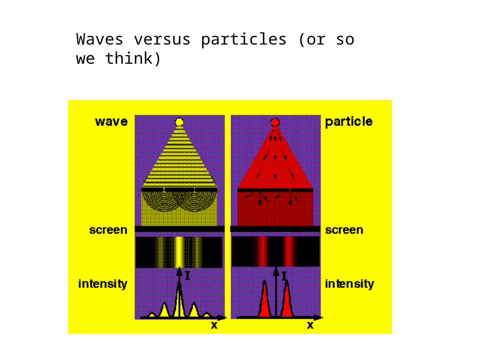
Waves versus particles (or so we think)
http://micro.magnet.fsu.edu/primer/java/doubleslit/
You can change wavelength of laser and the distancebetween the two slits.
Cool demonstration of double slit on the web. See:
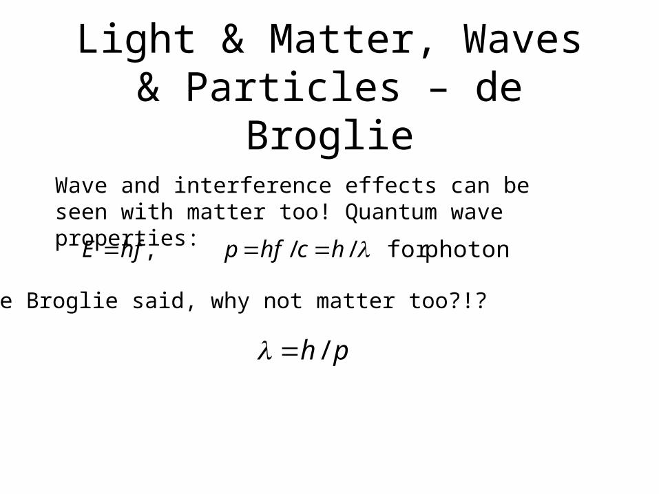
Light & Matter, Waves & Particles – de Broglie
Wave and interference effects can be seen with matter too! Quantum wave properties:
photonsfor //, hchfphfE
De Broglie said, why not matter too?!?
ph /
Interference properties seen with electrons, neutrons, atoms, and now even molecules like C60 and C70!
Interferometers or the Double Slit: Interference seen even when only one particle is in system. Particle (be it electron, photon, atom, etc) goes through both slits at once.
Observed interference of C60 and C70
See results of Prof. Anton Zeilinger and his group
http://www.quantum.univie.ac.at/research/
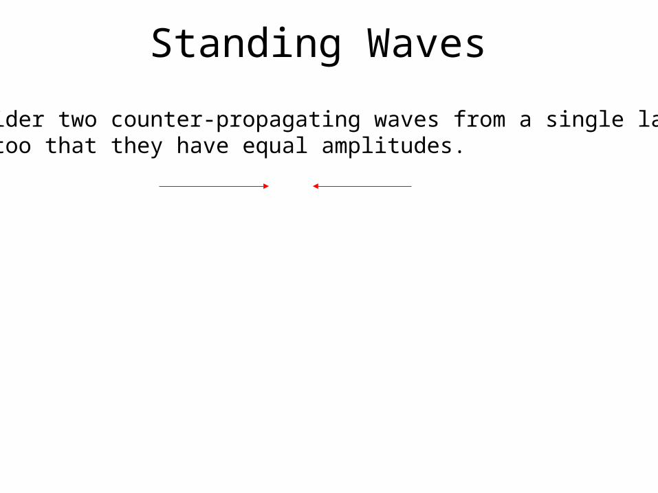
Standing Waves
Consider two counter-propagating waves from a single laser.Say too that they have equal amplitudes.

Standing Waves
Consider two counter-propagating waves from a single laser.Say too that they have equal amplitudes.
tkzEtkzEEtotal coscos 00
2/cos42cos22
2cos22
000
2221
kzIkzII
kzIIIII
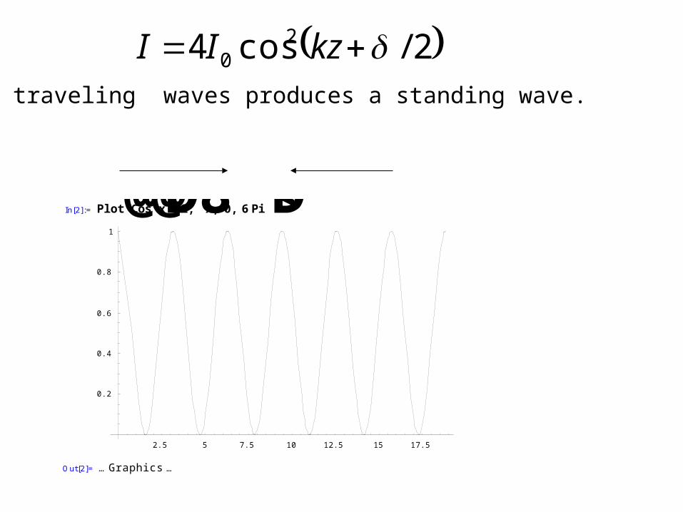
2/cos4 20 kzII
Two traveling waves produces a standing wave.
In[2]:= Plot@Cos@xD̂2,8x, 0, 6Pi<D
2.5 5 7.5 10 12.5 15 17.5
0.2
0.4
0.6
0.8
1
Out[2]= … Graphics …
Microwave OvensStanding microwaves
Peaks and troughs => Hot spots and cold spots => Nodes and anti-nodes
Spinning dish hopefully brings all parts of food into contact with nodes
Demo with marshmallows and a microwave
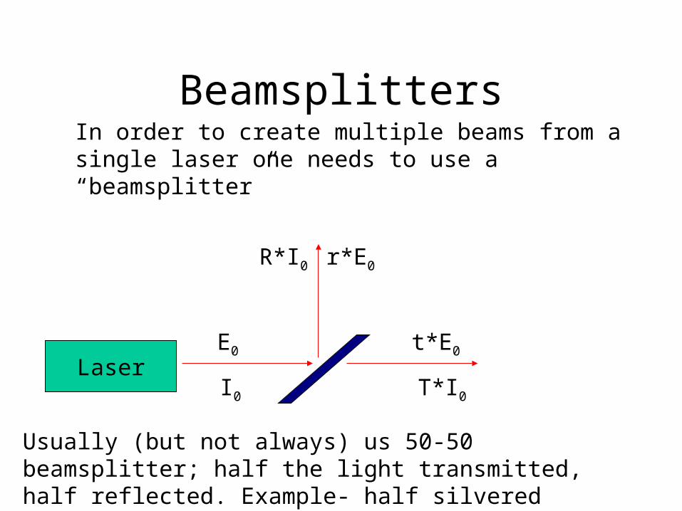
BeamsplittersIn order to create multiple beams from a single laser one needs to use a “beamsplitter”
LaserE0
r*E0
t*E0
I0
R*I0
T*I0
Usually (but not always) us 50-50 beamsplitter; half the light transmitted, half reflected. Example- half silvered mirror.
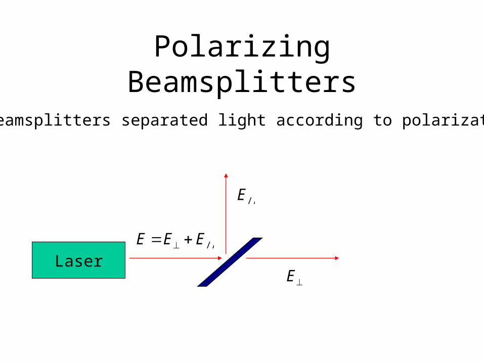
Polarizing Beamsplitters
Some beamsplitters separated light according to polarization
Laser//EEE
//E
E
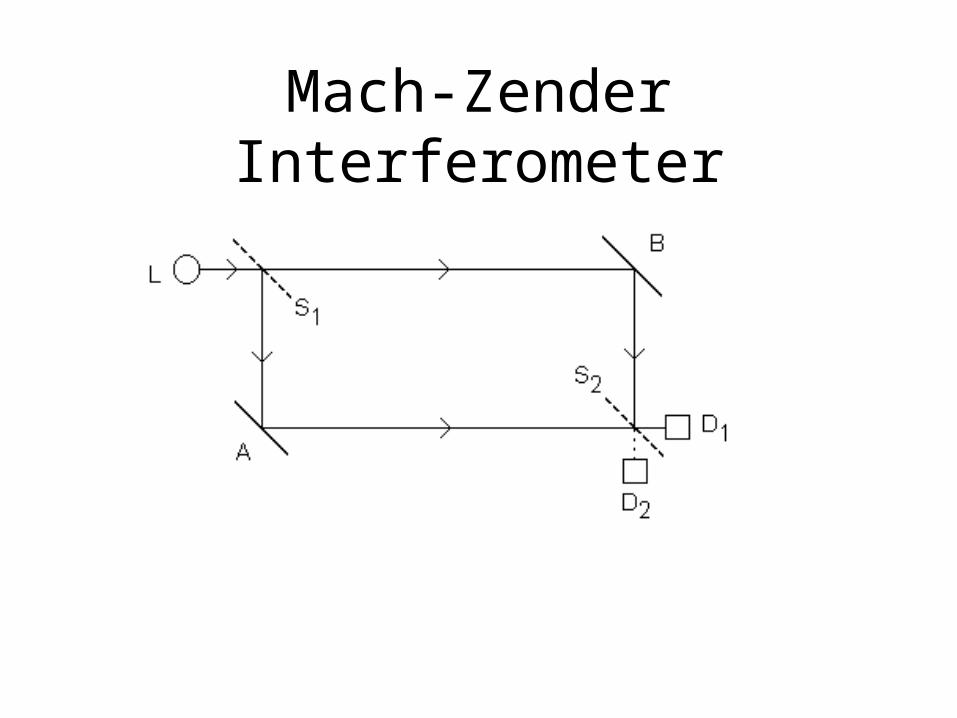
Mach-Zender Interferometer
Mach-Zender Interferometer
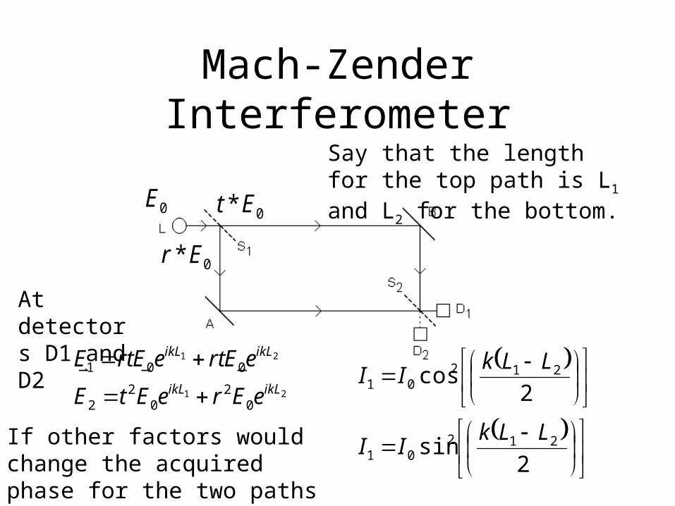
0E
0* Et
0* Er
Say that the length for the top path is L1 and L2 for the bottom.
21
21
02
02
2
001
ikLikL
ikLikL
eEreEtE
eErteErtE
At detectors D1 and D2
2sin
2cos
21201
21201
LLkII
LLkII
If other factors would change the acquired phase for the two paths it would affect counts at D1 and D2.
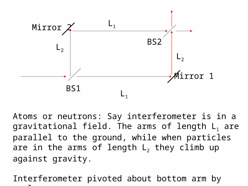
BS1
Mirror 1
Mirror 2
BS2L2
L2
L1
L1
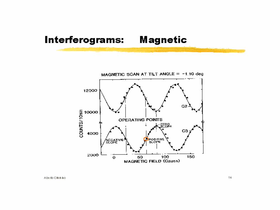
Atoms or neutrons: Say interferometer is in a gravitational field. The arms of length L1 are parallel to the ground, while when particles are in the arms of length L2 they climb up against gravity.
Interferometer pivoted about bottom arm by angle .
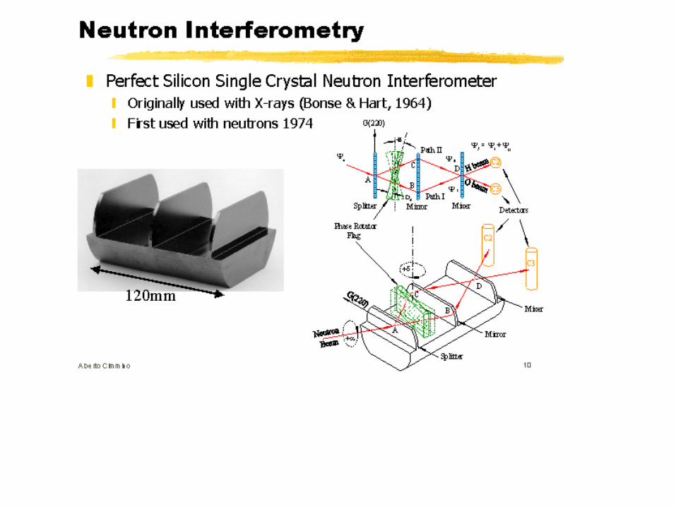
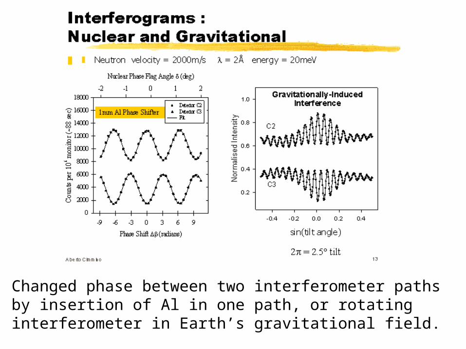
Changed phase between two interferometer paths by insertion of Al in one path, or rotating interferometer in Earth’s gravitational field.
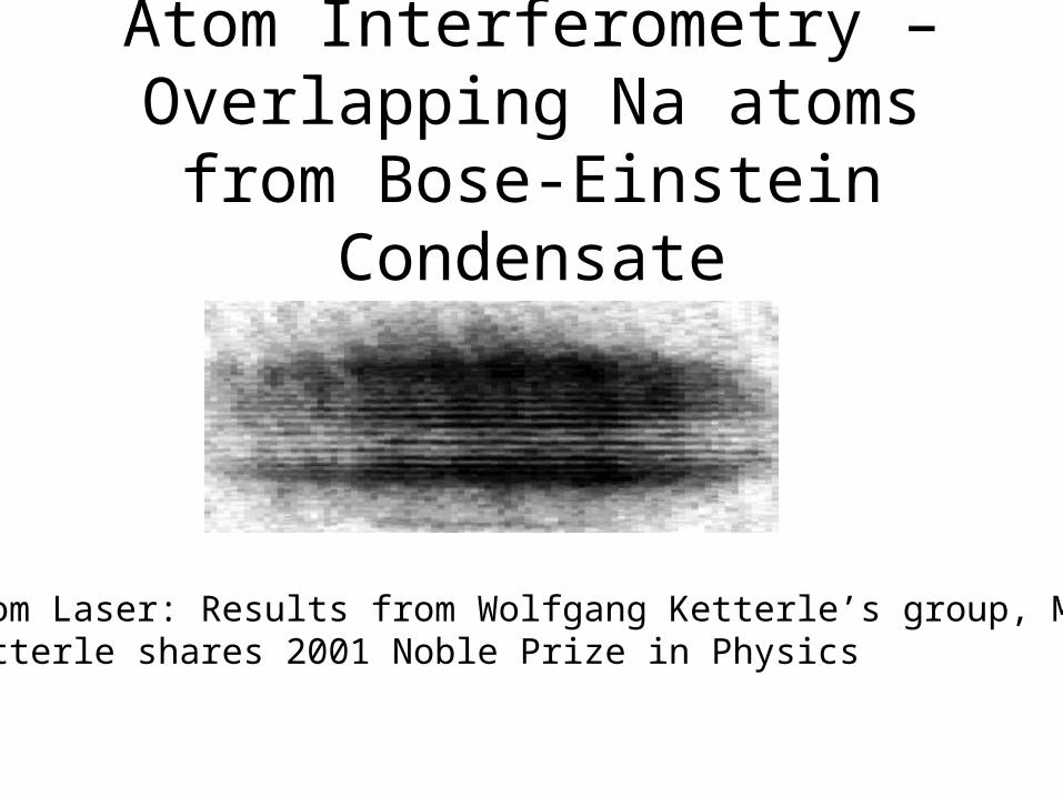
Atom Interferometry – Overlapping Na atoms from Bose-Einstein Condensate
Atom Laser: Results from Wolfgang Ketterle’s group, MIT.Ketterle shares 2001 Noble Prize in Physics
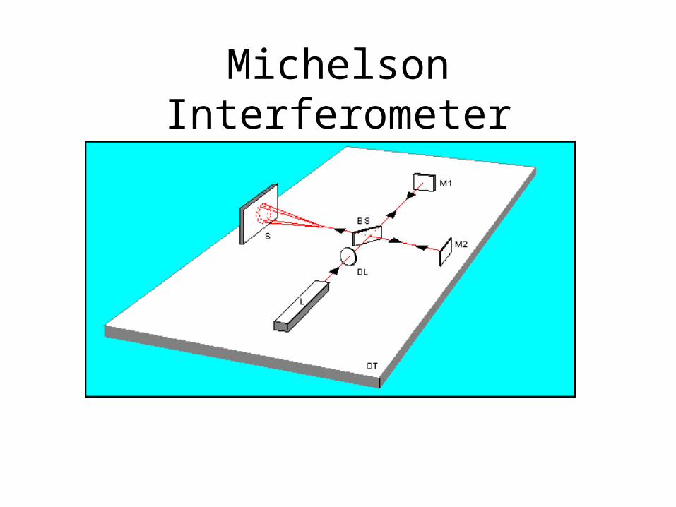
Michelson Interferometer
0E
L1
L2
I0
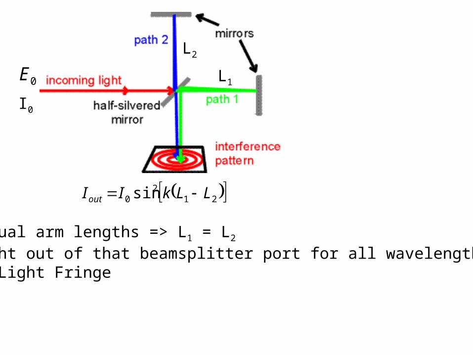
212
0 sin LLkIIout
For equal arm lengths => L1 = L2
No light out of that beamsplitter port for all wavelengths – White Light Fringe
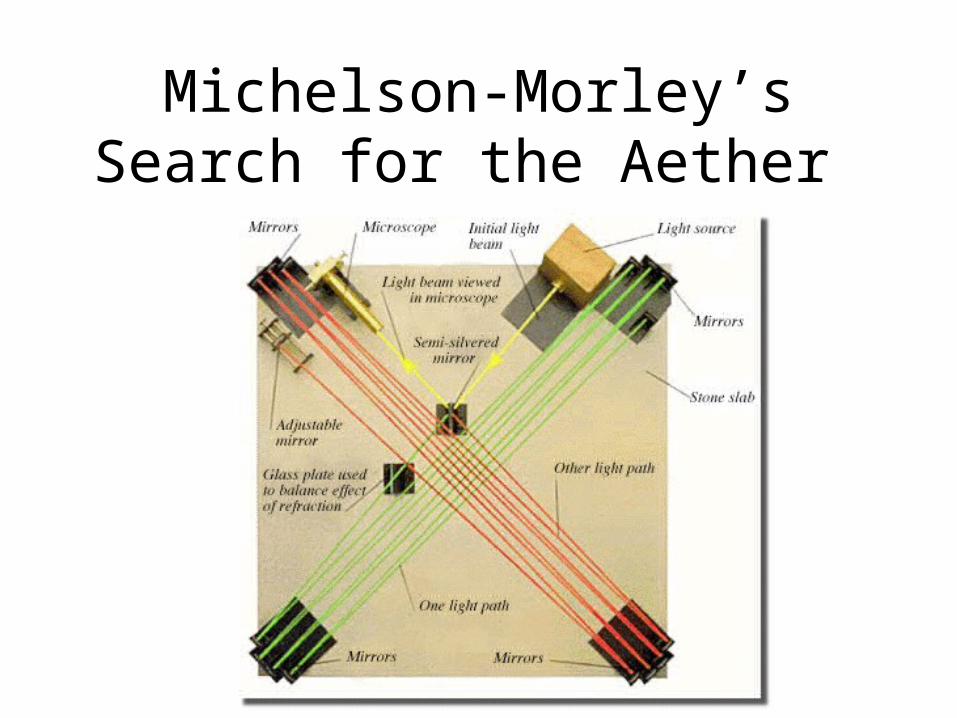
Michelson-Morley’s Search for the Aether
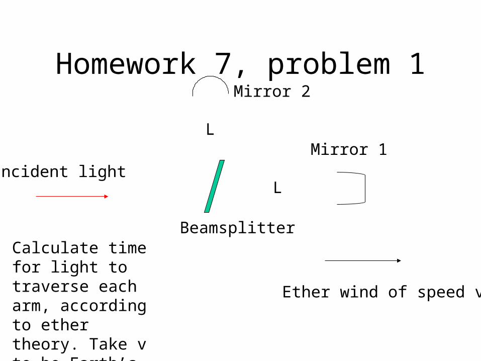
Homework 7, problem 1Mirror 2
Mirror 1
Beamsplitter
Incident light
L
L
Ether wind of speed v
Calculate time for light to traverse each arm, according to ether theory. Take v to be Earth’s orbital velocity.
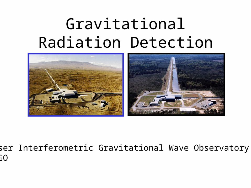
Gravitational Radiation Detection
Laser Interferometric Gravitational Wave ObservatoryLIGO
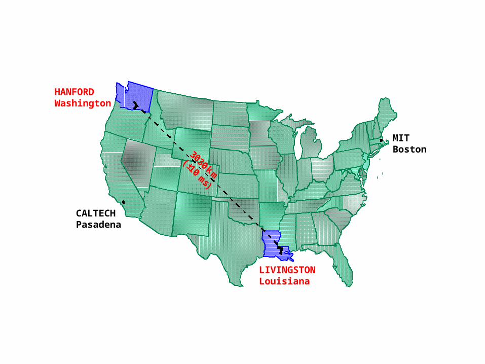
3030 km(±10 ms)
CALTECHPasadena
MITBoston
HANFORDWashington
LIVINGSTONLouisiana
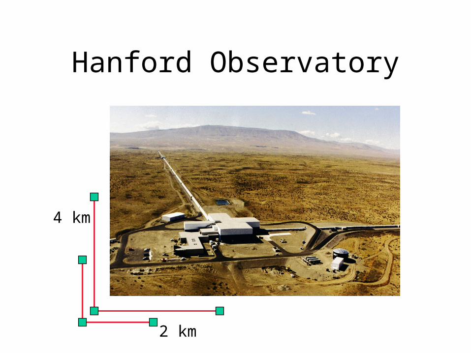
Hanford Observatory
4 km
2 km
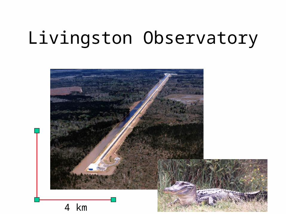
Livingston Observatory
4 km
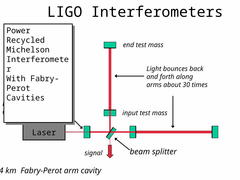
LIGO Interferometers
Laser
end test mass
Light bounces back and forth along arms about 30 times
input test massLight is “recycled” about 50 times
signal
Power RecycledMichelsonInterferometer With Fabry-Perot Cavities
Power RecycledMichelsonInterferometer With Fabry-Perot Cavities
4 km Fabry-Perot arm cavity
beam splitter
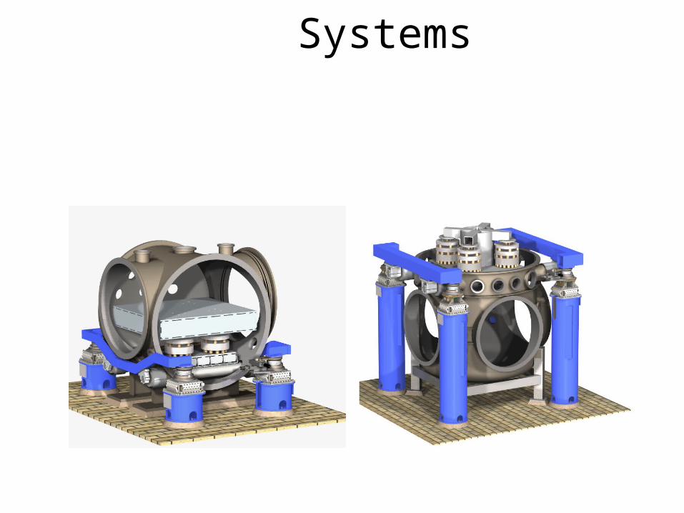
Vibration Isolation Systems
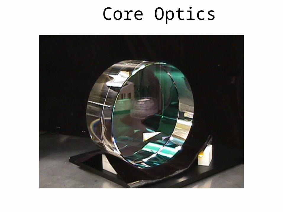
Core Optics
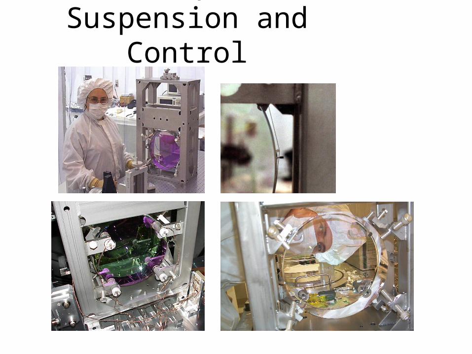
Core Optics Suspension and Control
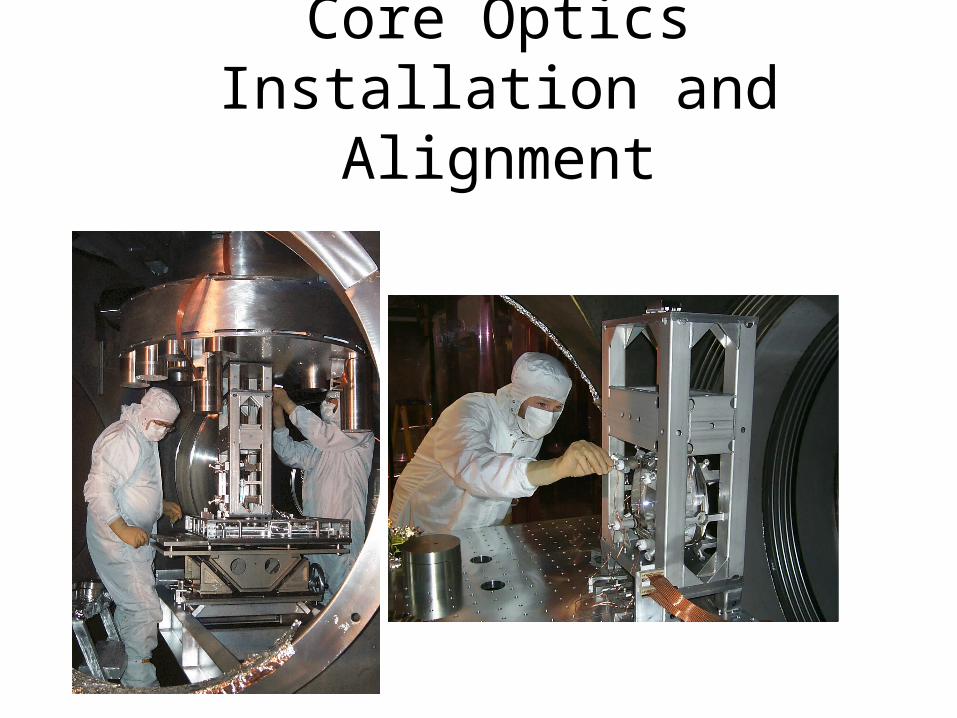
Core Optics Installation and Alignment
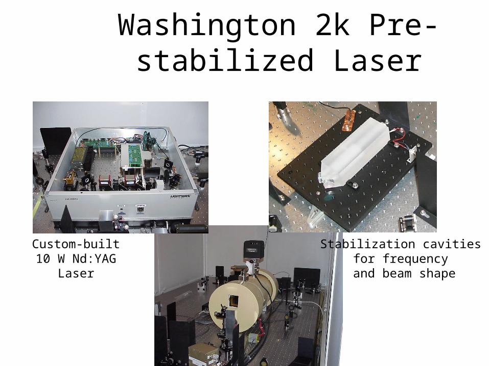
Washington 2k Pre-stabilized Laser
Custom-built10 W Nd:YAG
Laser
Stabilization cavities for frequency
and beam shape
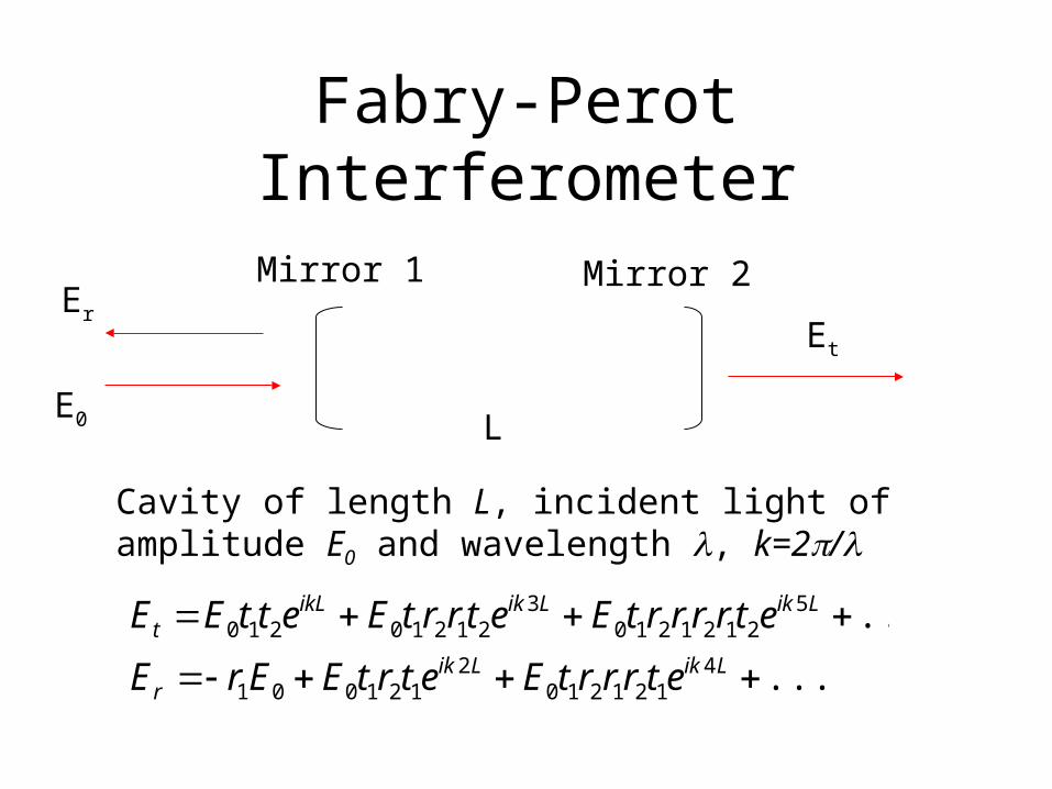
Fabry-Perot Interferometer
Mirror 1 Mirror 2
LE0
ErEt
...
...4
1212102
121001
52121210
321210210
LikLik
r
LikLikikLt
etrrrtEetrtEErE
etrrrrtEetrrtEettEE
Cavity of length L, incident light of amplitude E0 and wavelength , k=2/
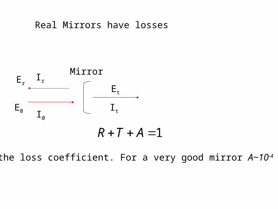
Mirror
E0
ErEt
Real Mirrors have losses
I0
Ir
It
1 ATR
A is the loss coefficient. For a very good mirror A~10-4 to 10-3
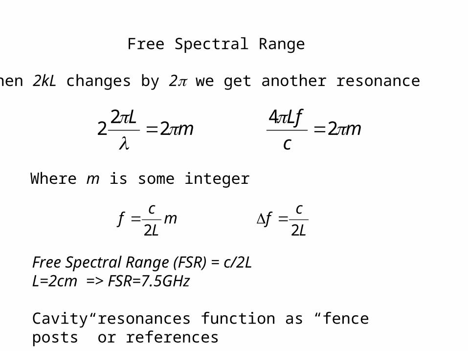
Free Spectral Range
When 2kL changes by 2 we get another resonance
mc
Lfm
L
24
22
2
Where m is some integer
L
cfm
L
cf
22
Free Spectral Range (FSR) = c/2LL=2cm => FSR=7.5GHz
Cavity resonances function as “fence posts” or references
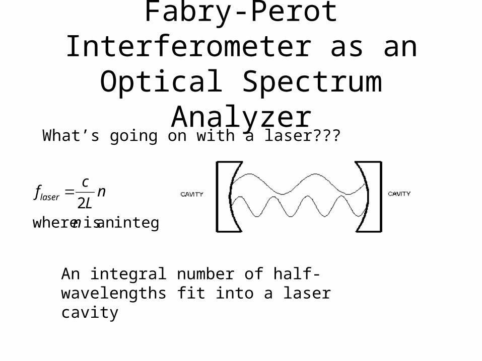
Fabry-Perot Interferometer as an Optical Spectrum Analyzer
What’s going on with a laser???
An integral number of half-wavelengths fit into a laser cavity
integeran is where2
n
nL
cflaser
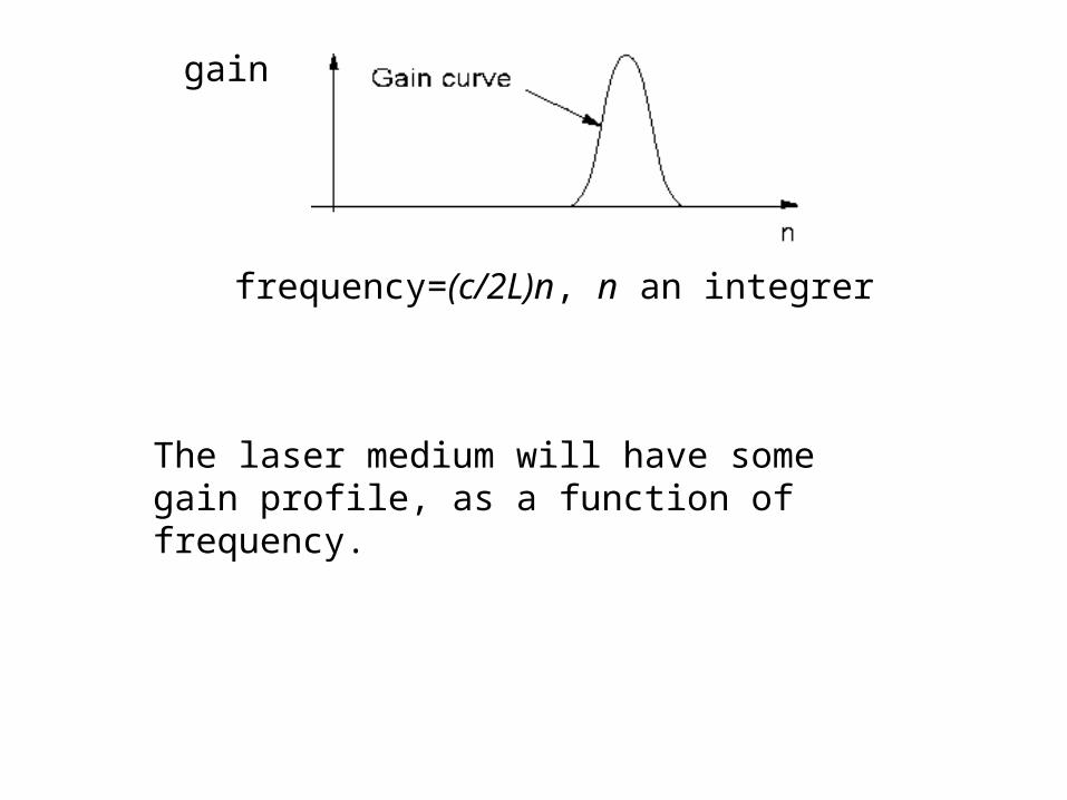
The laser medium will have some gain profile, as a function of frequency.
gain
frequency=(c/2L)n, n an integrer
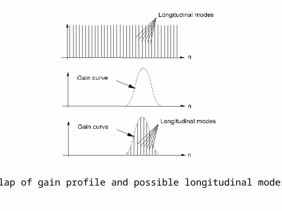
Overlap of gain profile and possible longitudinal modes
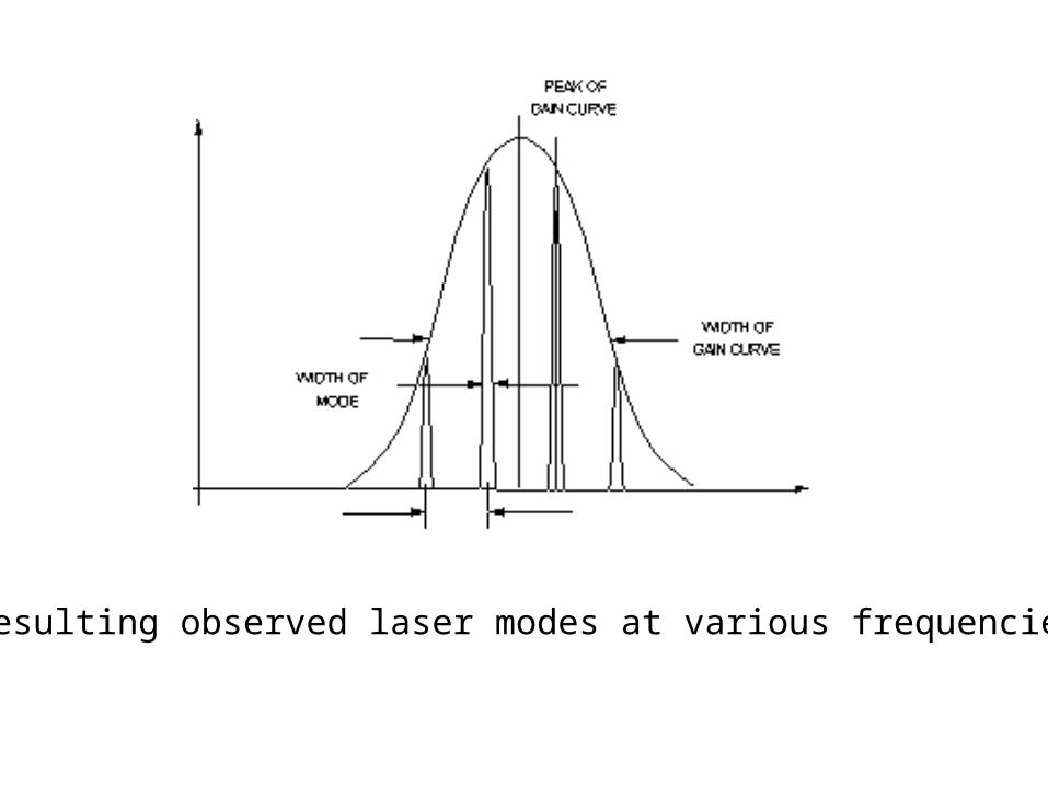
Resulting observed laser modes at various frequencies.
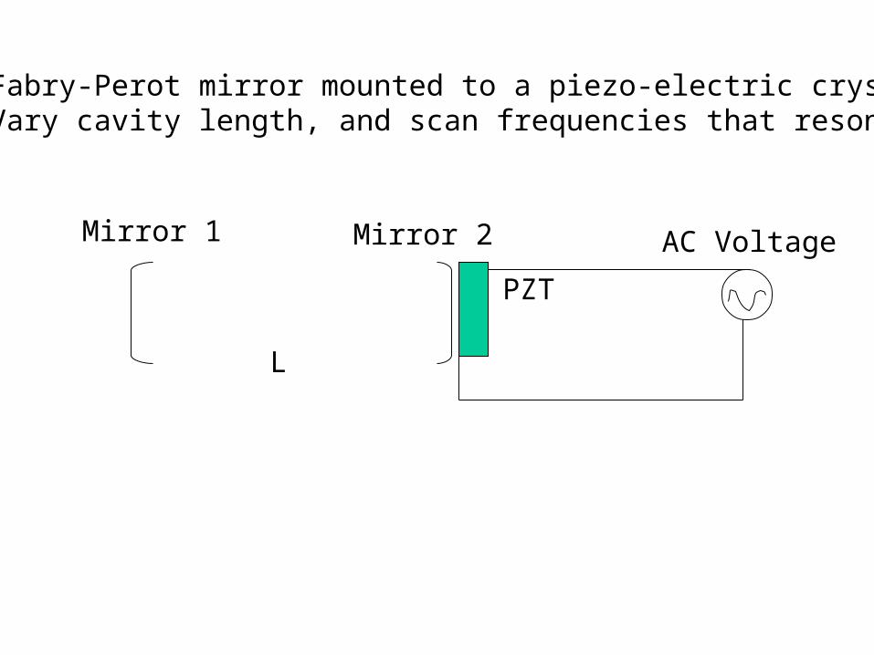
Mirror 1 Mirror 2
L
PZT
Fabry-Perot mirror mounted to a piezo-electric crystalVary cavity length, and scan frequencies that resonate
AC Voltage
The Speckle Effect


![Interference [Hecht Ch. 9] - Michigan State University [Hecht Ch. 9] Note: Read Ch. 3 & 7 E&M Waves and Superposition of Waves and Meet with TAs and/or Dr. Lai if necessary.](https://img.pdfslide.us/doc/110x75/5afeaa057f8b9a8b4d8f459b/interference-hecht-ch-9-michigan-state-university-hecht-ch-9-note-read.jpg)
![Interference [Hecht Ch. 9] - Michigan State University · 2010. 11. 2. · 18 Measurement of tempora l coherence ... the interference envelope, which gives the degree of coherence](https://img.pdfslide.us/doc/110x75/60bf93c4f1310212c7751678/interference-hecht-ch-9-michigan-state-university-2010-11-2-18-measurement.jpg)