Embed Size (px)
Citation preview
Interference Fringe Scale for AbsoluteOcular Fundus Measurement
Stephen J. Kennedy, Bernard Schwartz, Takenori Takamoto, and James K. T. Eu
Measurements of the human ocular fundus in the three spatial dimensions have not been absolutebecause measuring techniques have used the optical system of the eye as part of the total ophthal-moscopic system. The ophthalmoscopic magnification due to the total dioptric power of an individualeye can vary substantially from that of the average eye. A new method has been developed to forminterference fringes on the fundus so that the fringe spacing can be calculated within a small errorby using measured values. The photographed fringes then act as a scale at the fundus with the fringespacings serving as the graduations, thus allowing accurate absolute measurements of the fundusthrough the interfering ocular media. Invest Ophthalmol Vis Sci 24:169-174, 1983
Whenever the ocular fundus is being viewed orphotographed, the optics of the eye become part ofthe viewing or photographic system. Because the op-tical characteristics of individual eyes can vary sub-stantially, the absolute size of any fundus structurecannot be known for certain. Even a knowledge ofrefractive correction is not enough to calculate awaythis difficulty. Emmetropic eyes of varying sizes,which need no correction, can vary substantially intotal dioptric power.'
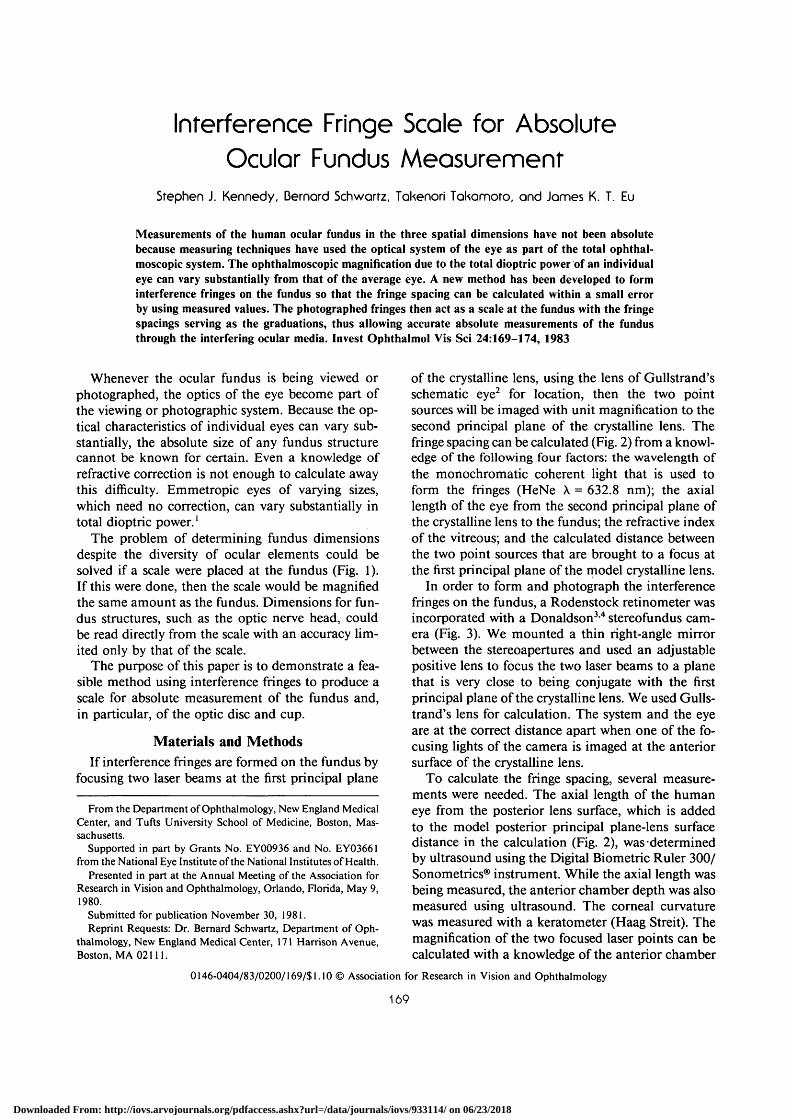
The problem of determining fundus dimensionsdespite the diversity of ocular elements could besolved if a scale were placed at the fundus (Fig. 1).If this were done, then the scale would be magnifiedthe same amount as the fundus. Dimensions for fun-dus structures, such as the optic nerve head, couldbe read directly from the scale with an accuracy lim-ited only by that of the scale.
The purpose of this paper is to demonstrate a fea-sible method using interference fringes to produce ascale for absolute measurement of the fundus and,in particular, of the optic disc and cup.
Materials and MethodsIf interference fringes are formed on the fundus by
focusing two laser beams at the first principal plane
From the Department of Ophthalmology, New England MedicalCenter, and Tufts University School of Medicine, Boston, Mas-sachusetts.
Supported in part by Grants No. EY00936 and No. EY03661from the National Eye Institute of the National Institutes of Health.
Presented in part at the Annual Meeting of the Association forResearch in Vision and Ophthalmology, Orlando, Florida, May 9,1980.
Submitted for publication November 30, 1981.Reprint Requests: Dr. Bernard Schwartz, Department of Oph-
thalmology, New England Medical Center, 171 Harrison Avenue,Boston, MA 02111.
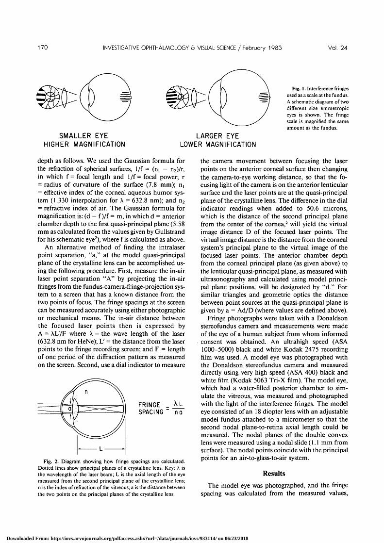
of the crystalline lens, using the lens of Gullstrand'sschematic eye2 for location, then the two pointsources will be imaged with unit magnification to thesecond principal plane of the crystalline lens. Thefringe spacing can be calculated (Fig. 2) from a knowl-edge of the following four factors: the wavelength ofthe monochromatic coherent light that is used toform the fringes (HeNe X = 632.8 nm); the axiallength of the eye from the second principal plane ofthe crystalline lens to the fundus; the refractive indexof the vitreous; and the calculated distance betweenthe two point sources that are brought to a focus atthe first principal plane of the model crystalline lens.
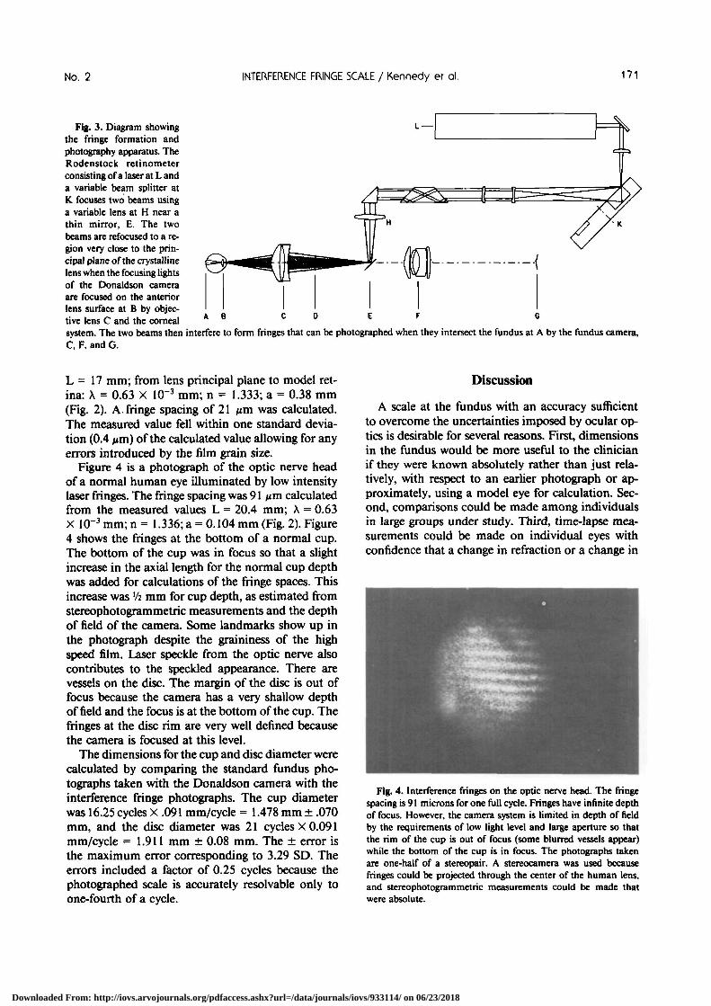
In order to form and photograph the interferencefringes on the fundus, a Rodenstock retinometer wasincorporated with a Donaldson34 stereofundus cam-era (Fig. 3). We mounted a thin right-angle mirrorbetween the stereoapertures and used an adjustablepositive lens to focus the two laser beams to a planethat is very close to being conjugate with the firstprincipal plane of the crystalline lens. We used Gulls-trand's lens for calculation. The system and the eyeare at the correct distance apart when one of the fo-cusing lights of the camera is imaged at the anteriorsurface of the crystalline lens.
To calculate the fringe spacing, several measure-ments were needed. The axial length of the humaneye from the posterior lens surface, which is addedto the model posterior principal plane-lens surfacedistance in the calculation (Fig. 2), was determinedby ultrasound using the Digital Biometric Ruler 300/Sonometrics® instrument. While the axial length wasbeing measured, the anterior chamber depth was alsomeasured using ultrasound. The corneal curvaturewas measured with a keratometer (Haag Streit). Themagnification of the two focused laser points can becalculated with a knowledge of the anterior chamber
0146-0404/83/0200/169/$ 1.10 © Association for Research in Vision and Ophthalmology
169
Downloaded From: http://iovs.arvojournals.org/pdfaccess.ashx?url=/data/journals/iovs/933114/ on 06/23/2018
170 INVESTIGATIVE OPHTHALMOLOGY b VISUAL SCIENCE / February 1983 Vol. 24
SMALLER EYEHIGHER MAGNIFICATION
LARGER EYELOWER MAGNIFICATION
Fig. 1. Interference fringesused as a scale at the fundus.A schematic diagram of twodifferent size emmetropiceyes is shown. The fringescale is magnified the sameamount as the fundus.
depth as follows. We used the Gaussian formula forthe refraction of spherical surfaces, 1/f = (n, - n2)/r,in which f = focal length and 1/f = focal power; r= radius of curvature of the surface (7.8 mm); n,= effective index of the corneal aqueous humor sys-tem (1.330 interpolation for X = 632.8 nm); and n2
= refractive index of air. The Gaussian formula formagnification is: (d - f )/f = m, in which d = anteriorchamber depth to the first quasi-principal plane (5.58mm as calculated from the values given by Gullstrandfor his schematic eye2), where f is calculated as above.
An alternative method of finding the intralaserpoint separation, "a," at the model quasi-principalplane of the crystalline lens can be accomplished us-ing the following procedure. First, measure the in-airlaser point separation "A" by projecting the in-airfringes from the fundus-camera-fringe-projection sys-tem to a screen that has a known distance from thetwo points of focus. The fringe spacings at the screencan be measured accurately using either photographicor mechanical means. The in-air distance betweenthe focused laser points then is expressed byA = XL'/F where X = the wave length of the laser(632.8 nm for HeNe); L' = the distance from the laserpoints to the fringe recording screen; and F = lengthof one period of the diffraction pattern as measuredon the screen. Second, use a dial indicator to measure
FRINGE _SPACING " na
Fig. 2. Diagram showing how fringe spacings are calculated.Dotted lines show principal planes of a crystalline lens. Key: A isthe wavelength of the laser beam; L is the axial length of the eyemeasured from the second principal plane of the crystalline lens;n is the index of refraction of the vitreous; a is the distance betweenthe two points on the principal planes of the crystalline lens.
the camera movement between focusing the laserpoints on the anterior corneal surface then changingthe camera-to-eye working distance, so that the fo-cusing light of the camera is on the anterior lenticularsurface and the laser points are at the quasi-principalplane of the crystalline lens. The difference in the dialindicator readings when added to 50.6 microns,which is the distance of the second principal planefrom the center of the cornea,5 will yield the virtualimage distance D of the focused laser points. Thevirtual image distance is the distance from the cornealsystem's principal plane to the virtual image of thefocused laser points. The anterior chamber depthfrom the corneal principal plane (as given above) tothe lenticular quasi-principal plane, as measured withultrasonography and calculated using model princi-pal plane positions, will be designated by "d." Forsimilar triangles and geometric optics the distancebetween point sources at the quasi-principal plane isgiven by a = Ad/D (where values are defined above).
Fringe photographs were taken with a Donaldsonstereofundus camera and measurements were madeof the eye of a human subject from whom informedconsent was obtained. An ultrahigh speed (ASA1000-5000) black and white Kodak 2475 recordingfilm was used. A model eye was photographed withthe Donaldson stereofundus camera and measureddirectly using very high speed (ASA 400) black andwhite film (Kodak 5063 Tri-X film). The model eye,which had a water-filled posterior chamber to sim-ulate the vitreous, was measured and photographedwith the light of the interference fringes. The modeleye consisted of an 18 diopter lens with an adjustablemodel fundus attached to a micrometer so that thesecond nodal plane-to-retina axial length could bemeasured. The nodal planes of the double convexlens were measured using a nodal slide (1.1 mm fromsurface). The nodal points coincide with the principalpoints for an air-to-glass-to-air system.
Results
The model eye was photographed, and the fringespacing was calculated from the measured values,
Downloaded From: http://iovs.arvojournals.org/pdfaccess.ashx?url=/data/journals/iovs/933114/ on 06/23/2018
No. 2 INTERFERENCE FRINGE SCALE / Kennedy er ol. 171
Fig. 3. Diagram showingthe fringe formation andphotography apparatus. TheRodenstock retinometerconsisting of a laser at L anda variable beam splitter atK focuses two beams usinga variable lens at H near athin mirror, E. The twobeams are refocused to a re-gion very close to the prin-cipal plane of the crystallinelens when the focusing lightsof the Donaldson cameraare focused on the anteriorlens surface at B by objec-tive lens C and the cornea!system. The two beams then interfere to form fringes that can be photographed when they intersect the fundus at A by the fundus camera,C, F, and G.
L = 17 mm; from lens principal plane to model ret-ina: X = 0.63 X 1(T3 mm; n = 1.333; a = 0.38 mm(Fig. 2). A fringe spacing of 21 nm was calculated.The measured value fell within one standard devia-tion (0.4 nm) of the calculated value allowing for anyerrors introduced by the film grain size.
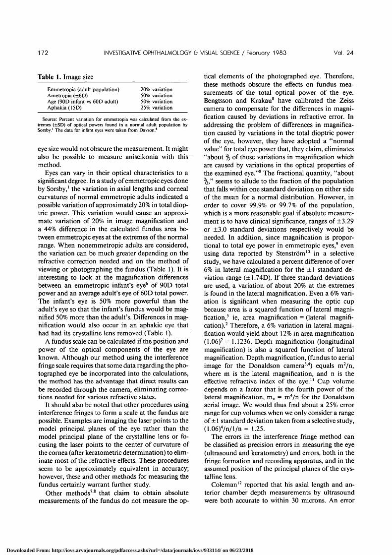
Figure 4 is a photograph of the optic nerve headof a normal human eye illuminated by low intensitylaser fringes. The fringe spacing was 91 fim calculatedfrom the measured values L = 20.4 mm; X = 0.63X 10~3 mm; n = 1.336; a = 0.104 mm (Fig. 2). Figure4 shows the fringes at the bottom of a normal cup.The bottom of the cup was in focus so that a slightincrease in the axial length for the normal cup depthwas added for calculations of the fringe spaces. Thisincrease was Vi mm for cup depth, as estimated fromstereophotogrammetric measurements and the depthof field of the camera. Some landmarks show up inthe photograph despite the graininess of the highspeed film. Laser speckle from the optic nerve alsocontributes to the speckled appearance. There arevessels on the disc. The margin of the disc is out offocus because the camera has a very shallow depthof field and the focus is at the bottom of the cup. Thefringes at the disc rim are very well defined becausethe camera is focused at this level.
The dimensions for the cup and disc diameter werecalculated by comparing the standard fundus pho-tographs taken with the Donaldson camera with theinterference fringe photographs. The cup diameterwas 16.25 cycles X .091 mm/cycle = 1.478 mm ± .070mm, and the disc diameter was 21 cycles X 0.091mm/cycle = 1.911 mm ± 0.08 mm. The ± error isthe maximum error corresponding to 3.29 SD. Theerrors included a factor of 0.25 cycles because thephotographed scale is accurately resolvable only toone-fourth of a cycle.
Discussion
A scale at the fundus with an accuracy sufficientto overcome the uncertainties imposed by ocular op-tics is desirable for several reasons. First, dimensionsin the fundus would be more useful to the clinicianif they were known absolutely rather than just rela-tively, with respect to an earlier photograph or ap-proximately, using a model eye for calculation. Sec-ond, comparisons could be made among individualsin large groups under study. Third, time-lapse mea-surements could be made on individual eyes withconfidence that a change in refraction or a change in
Fig. 4. Interference fringes on the optic nerve head. The fringespacing is 91 microns for one full cycle. Fringes have infinite depthof focus. However, the camera system is limited in depth of fieldby the requirements of low light level and large aperture so thatthe rim of the cup is out of focus (some blurred vessels appear)while the bottom of the cup is in focus. The photographs takenare one-half of a stereopair. A stereocamera was used becausefringes could be projected through the center of the human lens,and stereophotogrammetric measurements could be made thatwere absolute.
Downloaded From: http://iovs.arvojournals.org/pdfaccess.ashx?url=/data/journals/iovs/933114/ on 06/23/2018
172 INVESTIGATIVE OPHTHALMOLOGY & VISUAL SCIENCE / February 1983 Vol. 24
Table 1. Image size
Emmetropia (adult population)Ametropia (±6D)Age (90D infant vs 60D adult)Aphakia(15D)
20% variation50% variation50% variation25% variation
Source: Percent variation for emmetropia was calculated from the ex-tremes (±SD) of optical powers found in a normal adult population bySorsby.1 The data for infant eyes were taken from Davson.6
eye size would not obscure the measurement. It mightalso be possible to measure aniseikonia with thismethod.
Eyes can vary in their optical characteristics to asignificant degree. In a study of emmetropic eyes doneby Sorsby,1 the variation in axial lengths and cornealcurvatures of normal emmetropic adults indicated apossible variation of approximately 20% in total diop-tric power. This variation would cause an approxi-mate variation of 20% in image magnification anda 44% difference in the calculated fundus area be-tween emmetropic eyes at the extremes of the normalrange. When nonemmetropic adults are considered,the variation can be much greater depending on therefractive correction needed and on the method ofviewing or photographing the fundus (Table 1). It isinteresting to look at the magnification differencesbetween an emmetropic infant's eye6 of 90D totalpower and an average adult's eye of 60D total power.The infant's eye is 50% more powerful than theadult's eye so that the infant's fundus would be mag-nified 50% more than the adult's. Differences in mag-nification would also occur in an aphakic eye thathad had its crystalline lens removed (Table 1).
A fundus scale can be calculated if the position andpower of the optical components of the eye areknown. Although our method using the interferencefringe scale requires that some data regarding the pho-tographed eye be incorporated into the calculations,the method has the advantage that direct results canbe recorded through the camera, eliminating correc-tions needed for various refractive states.
It should also be noted that other procedures usinginterference fringes to form a scale at the fundus arepossible. Examples are imaging the laser points to themodel principal planes of the eye rather than themodel principal plane of the crystalline lens or fo-cusing the laser points to the center of curvature ofthe cornea (after keratometric determination) to elim-inate most of the refractive effects. These proceduresseem to be approximately equivalent in accuracy;however, these and other methods for measuring thefundus certainly warrant further study.
Other methods7-8 that claim to obtain absolutemeasurements of the fundus do not measure the op-
tical elements of the photographed eye. Therefore,these methods obscure the effects on fundus mea-surements of the total optical power of the eye.Bengtsson and Krakau8 have calibrated the Zeisscamera to compensate for the differences in magni-fication caused by deviations in refractive error. Inaddressing the problem of differences in magnifica-tion caused by variations in the total dioptric powerof the eye, however, they have adopted a "normalvalue" for total eye power that, they claim, eliminates"about 2/3 of those variations in magnification whichare caused by variations in the optical properties ofthe examined eye."8 The fractional quantity, "about%," seems to allude to the fraction of the populationthat falls within one standard deviation on either sideof the mean for a normal distribution. However, inorder to cover 99.9% or 99.7% of the population,which is a more reasonable goal if absolute measure-ment is to have clinical significance, ranges of ±3.29or ±3.0 standard deviations respectively would beneeded. In addition, since magnification is propor-tional to total eye power in emmetropic eyes,9 evenusing data reported by Stenstrom10 in a selectivestudy, we have calculated a percent difference of over6% in lateral magnification for the ± 1 standard de-viation range (±1.74D). If three standard deviationsare used, a variation of about 20% at the extremesis found in the lateral magnification. Even a 6% vari-ation is significant when measuring the optic cupbecause area is a squared function of lateral magni-fication,5 ie, area magnification = (lateral magnifi-cation).2 Therefore, a 6% variation in lateral magni-fication would yield about 12% in area magnification(1.06)2= 1.1236. Depth magnification (longitudinalmagnification) is also a squared function of lateralmagnification. Depth magnification, (fundus to aerialimage for the Donaldson camera34) equals m2/n,where m is the lateral magnification, and n is theeffective refractive index of the eye.'' Cup volumedepends on a factor that is the fourth power of thelateral magnification, mv = m4/n for the Donaldsonaerial image. We would thus find about a 25% errorrange for cup volumes when we only consider a rangeof ± 1 standard deviation taken from a selective study,(1.06)4/n/l/n = 1.25.
The errors in the interference fringe method canbe classified as precision errors in measuring the eye(ultrasound and keratometry) and errors, both in thefringe formation and recording apparatus, and in theassumed position of the principal planes of the crys-talline lens.
Coleman12 reported that his axial length and an-terior chamber depth measurements by ultrasoundwere both accurate to within 30 microns. An error
Downloaded From: http://iovs.arvojournals.org/pdfaccess.ashx?url=/data/journals/iovs/933114/ on 06/23/2018
No. 2 INTERFERENCE FRINGE SCALE / Kennedy er ol. 173
of this magnitude will yield two errors: one in fringespacing of 0.6% because of the limitations of the axiallength measurement and the other of 0.15% becauseof anterior chamber tolerance.
In our study keratometric measurement was lim-ited by the precision of the scale, so that it was ac-curate to 'AD. The power of the corneal-anteriorchamber system (43.08D) divided by ViD equals ap-proximately 0.6%, which would also be the error inthe fringe spacings.
If optimal precision is achieved, errors attributableto the limitations of ultrasound and the keratometerare on the order of 1.5%.
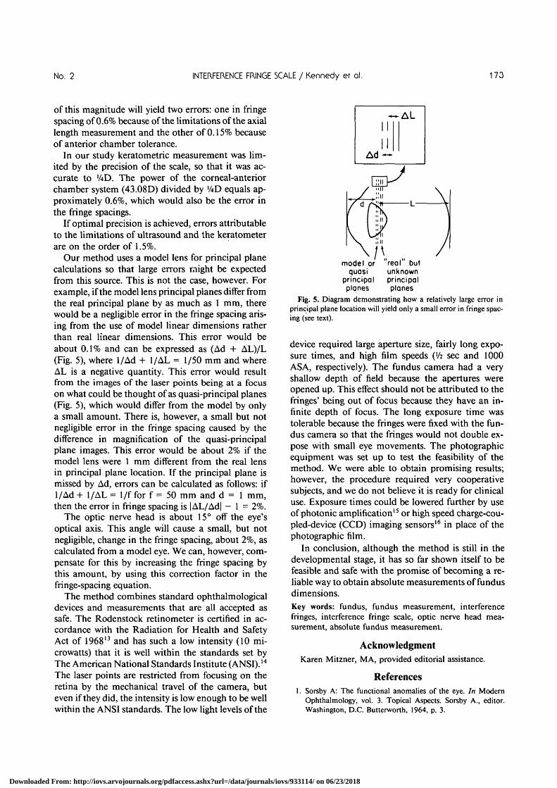
Our method uses a model lens for principal planecalculations so that large errors might be expectedfrom this source. This is not the case, however. Forexample, if the model lens principal planes differ fromthe real principal plane by as much as 1 mm, therewould be a negligible error in the fringe spacing aris-ing from the use of model linear dimensions ratherthan real linear dimensions. This error would beabout 0.1% and can be expressed as (Ad + AL)/L(Fig. 5), where 1/Ad + 1/AL = 1/50 mm and whereAL is a negative quantity. This error would resultfrom the images of the laser points being at a focuson what could be thought of as quasi-principal planes(Fig. 5), which would differ from the model by onlya small amount. There is, however, a small but notnegligible error in the fringe spacing caused by thedifference in magnification of the quasi-principalplane images. This error would be about 2% if themodel lens were 1 mm different from the real lensin principal plane location. If the principal plane ismissed by Ad, errors can be calculated as follows: if1/Ad + 1/AL = 1/f for f = 50 mm and d = 1 mm,then the error in fringe spacing is |AL/Ad| - 1 = 2%.
The optic nerve head is about 15° off the eye'soptical axis. This angle will cause a small, but notnegligible, change in the fringe spacing, about 2%, ascalculated from a model eye. We can, however, com-pensate for this by increasing the fringe spacing bythis amount, by using this correction factor in thefringe-spacing equation.
The method combines standard ophthalmologicaldevices and measurements that are all accepted assafe. The Rodenstock retinometer is certified in ac-cordance with the Radiation for Health and SafetyAct of 196813 and has such a low intensity (10 mi-crowatts) that it is well within the standards set byThe American National Standards Institute (ANSI).14
The laser points are restricted from focusing on theretina by the mechanical travel of the camera, buteven if they did, the intensity is low enough to be wellwithin the ANSI standards. The low light levels of the
•*-II
Ad —
AL
model or "real butquasi unknown
principal principalplanes planes
Fig. 5. Diagram demonstrating how a relatively large error inprincipal plane location will yield only a small error in fringe spac-ing (see text).
device required large aperture size, fairly long expo-sure times, and high film speeds (xh sec and 1000ASA, respectively). The fundus camera had a veryshallow depth of field because the apertures wereopened up. This effect should not be attributed to thefringes' being out of focus because they have an in-finite depth of focus. The long exposure time wastolerable because the fringes were fixed with the fun-dus camera so that the fringes would not double ex-pose with small eye movements. The photographicequipment was set up to test the feasibility of themethod. We were able to obtain promising results;however, the procedure required very cooperativesubjects, and we do not believe it is ready for clinicaluse. Exposure times could be lowered further by useof photonic amplification15 or high speed charge-cou-pled-device (CCD) imaging sensors16 in place of thephotographic film.
In conclusion, although the method is still in thedevelopmental stage, it has so far shown itself to befeasible and safe with the promise of becoming a re-liable way to obtain absolute measurements of fundusdimensions.Key words: fundus, fundus measurement, interferencefringes, interference fringe scale, optic nerve head mea-surement, absolute fundus measurement.
AcknowledgmentKaren Mitzner, MA, provided editorial assistance.
References1. Sorsby A: The functional anomalies of the eye. In Modern
Ophthalmology, vol. 3. Topical Aspects. Sorsby A., editor.Washington, D.C. Butterworth, 1964, p. 3.
Downloaded From: http://iovs.arvojournals.org/pdfaccess.ashx?url=/data/journals/iovs/933114/ on 06/23/2018
174 INVESTIGATIVE OPHTHALMOLOGY & VISUAL SCIENCE / Februory 1983 Vol. 24
2. Von Helmholtz HLF: Handbuch Der physiologischen Optik.2nd ed. Hamburg, Leopold Voss, 1896, vol. 1, pp. 351 and391.
3. Donaldson DD: Stereophotographic systems. Int OphthalmolClin 16(2): 109, 1976.
4. Donaldson DD, Prescott R, and Kennedy S: Simultaneousstereoscopic fundus camera incorporating a single optical axis.Invest Ophthalmol Vis Sci 19:289, 1980.
5. Duke-Elder S, ed: System of Ophthalmology, Vol. 5:Ophthalmic Optics and Refraction. St. Louis, CV Mosby,1970, p. 118.
6. Bennett AG and Francis JL: Ametropia and its correction. InThe Eye. Vol. 4. Visual Optics and the Optical Space Sense.Davson, H, editor. New York, Academic Press, 1962, p. 144.
7. Bengtsson B: The variation and covariation of cup and discdiameters. Acta Ophthalmol 54:804, 1976.
8. Bengtsson B and Krakau CET: Some essential optical featuresof the Zeiss fundus camera. Acta Ophthalmol 55:123, 1977.
9. Duke-Elder S, ed: System of Ophthalmology, Vol. 5.
Ophthalmic Optics and Refraction. St. Louis, CV Mosby,1970, p. 847.
10. Stenstrom S: Investigation of the variation and the correlationof the optical elements of human eyes. Am J Optom 25:218,1948.
11. Kavanagh AJ: Stereoscopic imagery in a type of stereoscopicmicroscope. Appl Optics 8:913, 1969.
12. Coleman DJ: Ultrasonic measurement of eye dimensions. IntOphthalmol Clin 19(4):225, 1979.
13. Mallow R and Chabot L: Laser Safety Handbook. New York,Van Nostrand Reinhold, 1978, p. 326.
14. American National Standards for the Safe Use of Lasers, 1-1976. New York, American National Standards Institute,1979, p. Z136.
15. Czwakiel RP and Scott EC: Concurrent photon amplification(CPA) applied to small format camera systems. Proc Soc PhotoOptic Instr Eng 58:192, 1975.
16. Laurin TC: The Optical Industry and Systems Directory, vol.2. Pittsfield, Optical Publishing Co, 1979, p. El53.
Downloaded From: http://iovs.arvojournals.org/pdfaccess.ashx?url=/data/journals/iovs/933114/ on 06/23/2018