Embed Size (px)
Citation preview
Performance Evaluation 64 (2007) 994–1008www.elsevier.com/locate/peva
Interface split routing for finer-grained traffic engineering
Saqib Razaa,∗, Chen-Nee Chuahb
a Department of Computer Science, University of California, Davis, United Statesb Department of Computer and Electrical Engineering, University of California, Davis, United States
Available online 27 June 2007
Abstract
Legacy IP routing restricts the efficacy of traffic engineering solutions. This restriction stems from the constraint that trafficat a node must be uniformly split across all next-hop nodes corresponding to equal cost shortest path to a destination. Proposalsthat alleviate this constraint either completely overhaul legacy IP routing, or introduce complex control and/or forwarding planecomponents. This additional complexity departs from the elegant simplicity of legacy routing protocols where statically optimizedlink weights embed all traffic engineering semantics.
We present Interface Split Routing (ISR), which retains the basic forwarding and control mechanism of legacy IP routing.Furthermore, a set of link weights embed all traffic engineering semantics in ISR. However, ISR makes possible finer-grainedtraffic engineering by configuring independent sets of next-hops to a destination at each incoming interface. This lends itself wellto modern router architectures where each incoming interface has its own forwarding table. Consequently, at the aggregated nodelevel, traffic to a particular destination may be non-uniformly distributed across next-hop nodes. Hence, ISR allows additionalflexibility in routing traffic as compared to default IP routing while retaining its simplicity. We conduct simulation studies onrepresentative ISP topologies to compare ISR with traditional link-weight-optimized routing. ISR reduces the difference betweenoptimal routing and weight-optimized routing by 50%.c© 2007 Elsevier B.V. All rights reserved.
Keywords: Intra-domain routing; Traffic engineering; Autonomous system; Link-state routing protocol; OSPF; IS–IS
1. Introduction
Traffic engineering constitutes an indispensable function in large autonomous systems, maximizing the operationalefficiency of such networks [1]. Traffic engineering mechanisms are instrumental in achieving performance objectiveswith a given set of resources and deferring cost-intensive deployment of additional resources. The optimal solutionto the traffic engineering problem yields an explicit set of paths across which the given set of demands need to berouted [2]. We refer to routing across this optimal set of explicit routes as optimal routing. The extent to which trafficcan actually flow across such a designated set of routes is a function of the underlying routing protocol and the preciseforwarding mechanism.
∗ Corresponding author.E-mail addresses: [email protected] (S. Raza), [email protected] (C.-N. Chuah).
0166-5316/$ - see front matter c© 2007 Elsevier B.V. All rights reserved.doi:10.1016/j.peva.2007.06.017
S. Raza, C.-N. Chuah / Performance Evaluation 64 (2007) 994–1008 995
The destination-based routing paradigm of legacy IP routing does not support routing across explicit routes. Legacyintra-domain routing protocols like OSPF [3] and IS–IS [4] involve assigning and disseminating integer link weightsfor each directed link in the network. Data forwarding in the context of legacy IP routing must obey the following pairof stipulations:
• At any given node x , traffic destined to a destination node d can be forwarded to a node y, if and only if there existsa path ρ such that ρ is a shortest path from x to d with respect to the assigned link weights, and y immediatelyfollows x in ρ. We refer to y as a next-hop from x to d, and label this constraint the Shortest-Path (SP) constraint.
• In case there exist more than one next-hops from x to d, all traffic at x destined to d must be distributed uniformlyacross the next-hops. This constraint is referred to as the Equal Cost Multi Path (ECMP) constraint.
Legacy IP routing draws upon ECMP as a heuristic to load balance traffic across multiple next-hops. Thechallenge is to ascertain the degree to which traffic can be engineered while adhering to the legacy SP and ECMPimplementations. A retinue of solutions [1,5–9] have been proposed that are geared towards finding link weightassignments that achieve or approach the performance of optimal routing. These solutions work in conjunction withECMP and assume knowledge of the traffic matrix. However, the difference between optimal routing and link-weight-optimized routing using legacy routing protocols may be significant [9]. Other solutions necessitate deployment ofnew technology [10–13], or introduce additional control and/or forwarding plane components and extra managementcomplexity [14–16].
We present Interface Split Routing (ISR), that leverages the fact that modern router architectures maintain separateforwarding tables for each incoming interface [17]. However, these forwarding tables are interface-independent,i.e. forwarding tables at different incoming interfaces of a router still yield the same set of next-hops for a particulardestination. ISR uses multiple weights per link to configure interface-specific routing tables that yield different sets ofnext-hops to the same destination. This serves to relax the ECMP constraint, allowing greater flexibility in engineeringtraffic.
In this paper, we demonstrate how interface-specific forwarding tables can be configured while retaining the basicforwarding and control mechanism of legacy IP routing. Specifically, we show how statically assigned link weightscan embed all traffic engineering semantics required for ISR. An important contribution of this work is that it sets upthe weight assignment problem such that any algorithm for computing optimal link weights for legacy IP routing canbe adapted to compute multiple link weights for ISR. We prove that our scheme results in judicious configuration ofinterface-specific forwarding tables, and present simulation results that showcase the performance of ISR.
The rest of this paper is organized as follows: Section 2 formalizes the optimal routing problem and discussessolutions proposed in previous literature. Section 3 introduces the ISR scheme in the context of optimal routing andpresents the general framework for ISR. Sections 4 and 5 demonstrate how multiple link weights per link are calculatedand used to compute interface-specific forwarding tables. Section 6 gives the results of our simulation experimentsand we put forth our conclusions in Section 7.
2. Background and related work
2.1. The optimal routing problem
Traffic engineering involves routing a given set of traffic demands on a network to optimize user performance andnetwork resources. Traffic demands are provided in the form of a traffic matrix that represents traffic intensity at thegranularity of ingress–egress pairs. We let G(V, E) represent the given network. Furthermore, let Ωuv(u,v)∈V ×Vbe the given traffic matrix. We define ci j to be the capacity of link (i, j) ∈ E , and Xuv
i j to be the fraction of trafficbetween ingress–egress pair (u, v) ∈ V × V that traverses (i, j) ∈ E . The utilization of a link (i, j) is given byµi j = ci j
−1×
∑(u,v)∈V ×V (Xuv
i j × Ωuv). Routing must obey the flow conservation constraints:
∑i :(i, j)∈E
Xuvi j −
∑k:( j,k)∈E
Xuvjk =
0 if j 6= u and j 6= v
−1 if j = u1 if j = v
∀(u, v) ∈ V × V (1)
0 ≤ Xuvi j ≤ 1 ∀(i, j) ∈ E, ∀(u, v) ∈ V × V . (2)
996 S. Raza, C.-N. Chuah / Performance Evaluation 64 (2007) 994–1008
The more universal traffic engineering objective is to route all the demands while optimizing some measure of linkutilization. One such objective is minimizing the utilization of the most congested link, referred to as the min–max-utilization objective. The optimal routing problem with the min–max-utilization objective can be formulated as anLP [15]. Fortz et al. propose an alternative linear programming formulation that seeks to minimize a piece-wiseincreasing linear convex envelope of a non-linear link cost function. The reader can refer to [9] for details of the Fortz& Thorup metric.
The LPs solve for Xuvi j (i, j)∈E,(u,v)∈V ×V . In order to realize such a traffic distribution through legacy IP routing,
link weights should be assigned that achieve the distribution in the presence of the SP and ECMP constraints. The SPconstraint does not restrict us due to an important result [2] from LP Duality theory which states that given a set ofexplicit paths, there exists a link weight assignment, such that either the explicit paths are equivalent to shortest-pathrouting with respect to the weights, or there exists another set of paths which are shortest paths with respect to theassigned weights, and routing along this set of paths results in link utilization for each link being less than or equalto the values corresponding to the original paths. On the other hand, ECMP is a restrictive constraint and implies thatexplicit routing may not be achievable by shortest-path routing with statically assigned link weights. We will providean illustrative example in Section 3.1.
2.2. Existing solutions
One of the general class of solutions put forth in previous literature is optimized link weight assignment [1,5–9].These solutions are geared towards intelligently computing link weights for which shortest-path routing with ECMPyields the best traffic engineering performance. They assume knowledge of the traffic matrix. One of the most citedworks in this domain is [9]. The authors of [9] demonstrate that statically assigning link weights using a local searchheuristic performs close to optimal routing for topologies that are representative of actual networks. However, theyalso prove that for certain networks, the difference between optimal routing and any link-weight-optimized routingusing legacy routing protocols may be significant. This difference is attributable to the simplifying ECMP heuristicfor load balancing [2]. Optimal routing can be realized if it were possible to configure arbitrary distribution of trafficacross the set of next-hop nodes [2]. A number of proposals have been presented with the aim of achieving, or moreclosely approximating, optimal routing. Some of these proposals necessitate deployment of new technology such asMPLS, ATM, or Frame Relay PVCs [10–13]. For instance, MPLS with its characteristic segregation between thecontrol and forwarding plane, affords the ability to establish virtual connections between two points on an IP network,maintaining the flexibility and simplicity of an IP network while exploiting the ATM-like advantage of a connection-oriented network. Ingress routers of an MPLS network can classify packets into forwarding equivalence classes andencapsulate them with labels before forwarding them along pre-computed paths. These label switched paths can beset up to realize a desired set of explicit routes.
Other solutions [14–16] have been proposed to leverage the widespread deployment of legacy IP routing protocolsand avoid an overhaul of the underlying technology. They, however, introduce additional control and/or forwardingplane components and extra management complexity. For instance, [15] performs centralized flow optimization andrequires traffic split information to be disseminated across the network at regular intervals. [14] assumes knowledgeof traffic intensity information at the granularity of destination prefixes and involves separately configuring the set ofnext-hops on a per-prefix basis at each node. [16] requires dynamic link load information to be disseminated acrossthe network and changes to the forwarding mechanisms in the router’s data path. These proposals do achieve relativelyfine-grained routing of traffic. However, their additional complexity represents a significant departure from the simpleelegance of legacy routing protocols with optimized link weights, wherein statically assigned link weights embedtraffic engineering semantics.
3. Interface split routing
3.1. Motivation for ISR
We now discuss the general idea and motivation behind ISR. Most IP networks use link-state protocols such asOSPF [3] and IS–IS [4] for intra-domain routing. In such networks, every link is assigned a weight (or cost) andtraffic between nodes is routed along minimum cost paths. These networks are characterized by the destination-based
S. Raza, C.-N. Chuah / Performance Evaluation 64 (2007) 994–1008 997
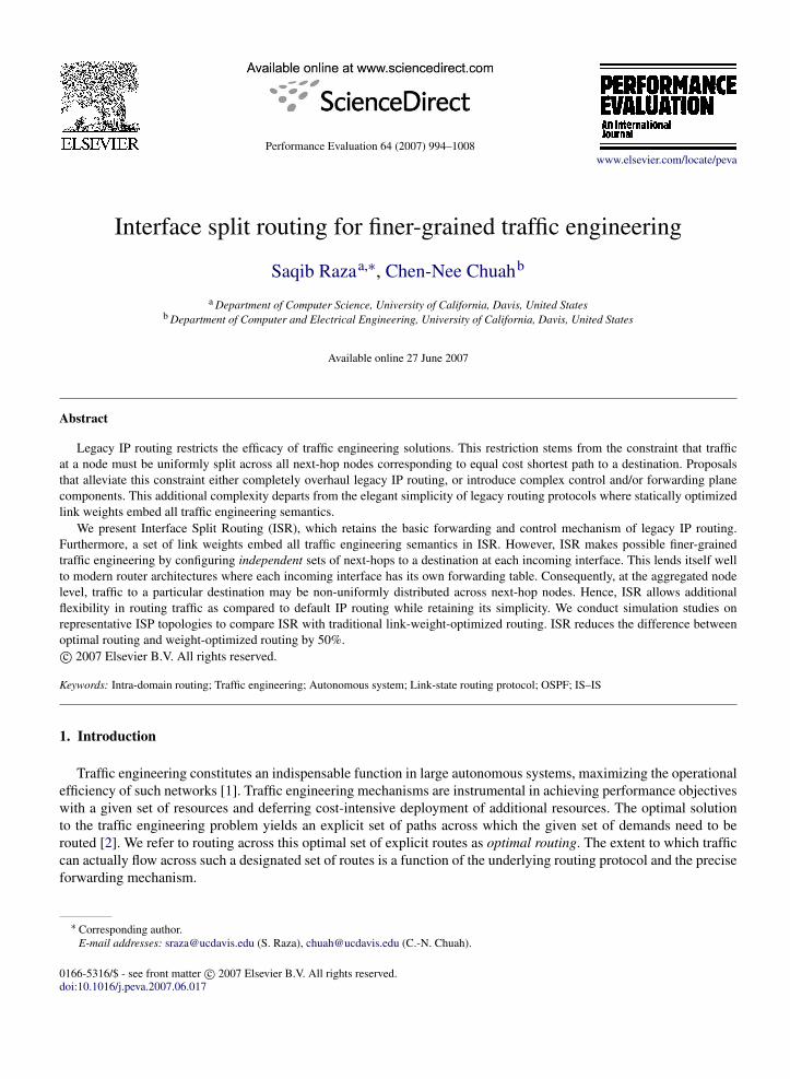
Fig. 1. ECMP constraint.
forwarding paradigm. A routing lookup comprises a longest-prefix match on a destination IP address to determine theset of nodes to which a packet may be forwarded. Since a prefix corresponds to a unique egress node in the network,this set comprises nodes that are next-hops from the node performing the lookup to the egress node.
Formally, let Λxd be the set of next-hops from x to d with respect to the assigned link weights. Each destinationprefix ρ has an egress node denoted by eρ
∈ V . Let λρx be the set of next-hops configured for prefix ρ at node x .
Shortest-path routing necessitates that λρx ⊆ Λxeρ . In reality, ECMP only implies that all traffic with prefix ρ at node
x gets uniformly distributed across the set of next-hops λρx . However, legacy IP routing sets λ
ρx = Λxeρ . It follows that
all traffic from x to d gets uniformly distributed across the set of next-hops Λxd .We stated in Section 2, that ECMP restricts us such that optimal routing may not be achievable by shortest-path
routing with statically assigned link weights. We now present an example to illustrate this claim. Fig. 1 shows ourexample network where the arc labels represent link capacities. We have to route 10 units of traffic from n1 to n6, anda further 15 units of traffic from n2 to n6. All traffic must aggregate at n3. The figure shows that there only exist twopaths from n3 to n6, denoted by p1 and p2. Let their costs be c1 and c2 respectively. Any link weight assignment willresult in one of the following: c1 = c2, c1 < c2, or c1 > c2. These translate into Λn3n6 = n4, n5, Λn3n6 = n4, orΛn3n6 = n5 respectively. The corresponding values for the maximum link utilization are 1/2, 1, and 1/4 respectively.Therefore, we cannot achieve maximum link utilization less than 1/4 with legacy IP routing. If it were possible toarbitrarily split traffic across next-hops, we could achieve a maximum link utilization of 1/5 in our example. Thiswould be the case if we route one-fifth of the traffic at n3 along p1 and the rest along p2.
The idea presented in [14] leverages the observation that λρx must only be a subset of Λxeρ . For instance, consider
three destination prefixes ρ1, ρ2, and ρ3 such that eρ1 = eρ2 = eρ3 = t . Further suppose that Λxt = a, b, c, d. Let thetraffic corresponding to ρ1, ρ2, and ρ3 that arrive at x be 4, 6, and 10 respectively. We wish to forward 2 units of trafficto next-hop b, 4 to d , and 7 each to a and c. Default IP routing only allows us to route 5 units of traffic across each ofthe four next-hops. However, we can configure λ
ρ1x = b, d, λ
ρ2x = a, c, d, and λ
ρ3x = a, c to achieve the desired
distribution. Hence, judiciously configuring the set of next-hops for each prefix gives a greater degree of freedom inengineering traffic.
Our solution, Interface-Specific Routing (ISR) follows in the same spirit as [14]. However, we judiciously configurethe set of next-hops at a per incoming interface rather than per-prefix granularity. We again refer to our earlierexample (Fig. 1) to illustrate the motivation to do so. Let λi
xd denote the set of next-hops for traffic destined to dthat arrives at x through the incoming interface1 (i, x). If it were possible to configure per-interface next-hops, we canset λ
n1n3n6 = n4, n5, and λ
n2n3n6 = n5. This causes 5 units of traffic to be routed across p1 and 20 units to be routed
across p2, for a maximum link utilization of only 1/5.The example illustrates how ISR affords greater flexibility in engineering traffic than default IP routing. The degree
of freedom of configuring next-hops per interface is less than the per-prefix case. However, the solution in [14]assumes knowledge of per-prefix traffic intensity information for every prefix whose next-hop is to be configured. Inaddition [14] requires additional control mechanisms to explicitly configure the next-hops. This contrasts sharply with
1 Without loss of generality, we assume that an interface corresponds to a single incoming link. ISR can easily be extended to multiple links perinterface.
998 S. Raza, C.-N. Chuah / Performance Evaluation 64 (2007) 994–1008
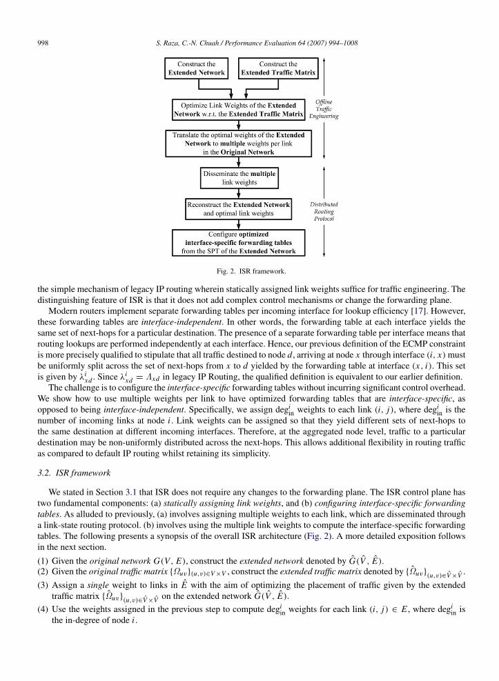
Fig. 2. ISR framework.
the simple mechanism of legacy IP routing wherein statically assigned link weights suffice for traffic engineering. Thedistinguishing feature of ISR is that it does not add complex control mechanisms or change the forwarding plane.
Modern routers implement separate forwarding tables per incoming interface for lookup efficiency [17]. However,these forwarding tables are interface-independent. In other words, the forwarding table at each interface yields thesame set of next-hops for a particular destination. The presence of a separate forwarding table per interface means thatrouting lookups are performed independently at each interface. Hence, our previous definition of the ECMP constraintis more precisely qualified to stipulate that all traffic destined to node d, arriving at node x through interface (i, x) mustbe uniformly split across the set of next-hops from x to d yielded by the forwarding table at interface (x, i). This setis given by λi
xd . Since λixd = Λxd in legacy IP Routing, the qualified definition is equivalent to our earlier definition.
The challenge is to configure the interface-specific forwarding tables without incurring significant control overhead.We show how to use multiple weights per link to have optimized forwarding tables that are interface-specific, asopposed to being interface-independent. Specifically, we assign degi
in weights to each link (i, j), where degiin is the
number of incoming links at node i . Link weights can be assigned so that they yield different sets of next-hops tothe same destination at different incoming interfaces. Therefore, at the aggregated node level, traffic to a particulardestination may be non-uniformly distributed across the next-hops. This allows additional flexibility in routing trafficas compared to default IP routing whilst retaining its simplicity.
3.2. ISR framework
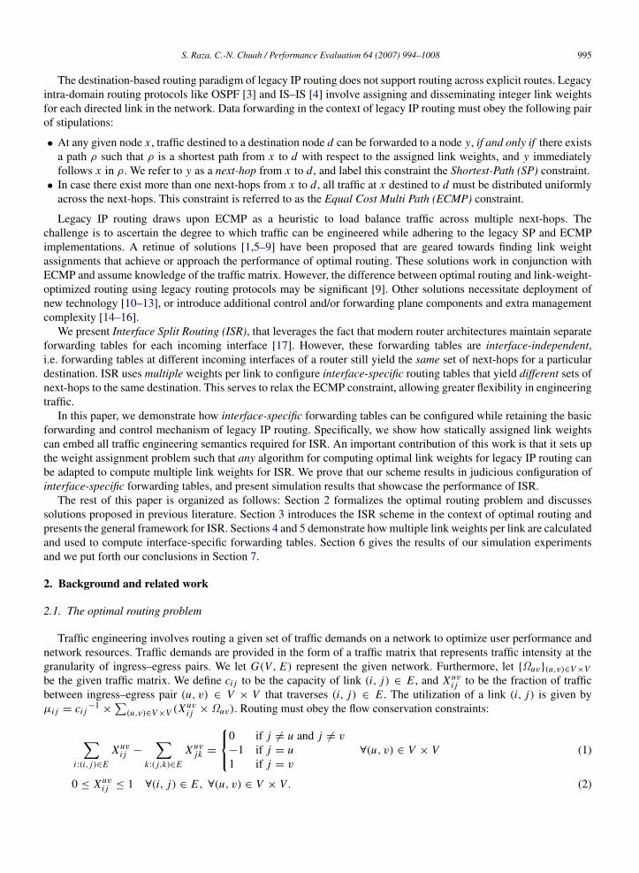
We stated in Section 3.1 that ISR does not require any changes to the forwarding plane. The ISR control plane hastwo fundamental components: (a) statically assigning link weights, and (b) configuring interface-specific forwardingtables. As alluded to previously, (a) involves assigning multiple weights to each link, which are disseminated througha link-state routing protocol. (b) involves using the multiple link weights to compute the interface-specific forwardingtables. The following presents a synopsis of the overall ISR architecture (Fig. 2). A more detailed exposition followsin the next section.
(1) Given the original network G(V, E), construct the extended network denoted by G(V , E).(2) Given the original traffic matrix Ωuv(u,v)∈V ×V , construct the extended traffic matrix denoted by Ωuv(u,v)∈V ×V .(3) Assign a single weight to links in E with the aim of optimizing the placement of traffic given by the extended
traffic matrix Ωuv(u,v)∈V ×V on the extended network G(V , E).(4) Use the weights assigned in the previous step to compute degi
in weights for each link (i, j) ∈ E , where degiin is
the in-degree of node i .
S. Raza, C.-N. Chuah / Performance Evaluation 64 (2007) 994–1008 999
(5) Disseminate the multiple link weights across the network using a link-state routing protocol. As a result, distributednodes can populate their extended link-state database.
(6) At each node, locally reconstruct the extended network G(V , E) and weights assigned to links in E from theextended link-state database.
(7) Run Dijkstra locally to compute the set of next-hop nodes for node-destination pairs with respect to G(V , E).(8) Translate the set of next-hops into interface-specific forwarding tables at each interface and subsequently populate
the forwarding table at each incoming interface.
Steps (1)–(5) outline the computation and assignment of multiple link weights. The weights are computed torepresent the optimal choice of interface-specific next-hops for each node in the network. This is explained inSection 4. Steps (6)–(8) delineate how interface-specific forwarding tables are computed from the multiple linkweights. The details of this computation follow in Section 5.
4. Multiple link weight assignment
In default IP routing, we use knowledge of the traffic matrix Ωuv(u,v)∈V ×V to optimize the weights for linksin the network G(V, E). These weights are then assigned to links and propagated across the network via link-staterouting protocols. Nodes can then run a shortest-path algorithm. Interface-independent forwarding tables are simplyconfigured by setting next-hop nodes for a prefix to be nodes that are immediately downstream of the shortest pathfrom the node to the egress node for the prefix. In ISR we must optimize the weights in a way that leverages the abilityto have interface-specific forwarding tables. Secondly, we must distribute enough information that allows each nodeto configure the desired interface-specific forwarding tables.
We will show how this can be accomplished by statically assigning and thereafter disseminating degiin weights for
each link (i, j) ∈ E , where degiin is the in-degree of node i . The following discussion shows how this is done.
4.1. Construct the extended network
We first construct an extended network G(V , E) from our original network G(V, E). We construct a source nodesi for every node i ∈ V . Let S =
⋃i∈V si be the set of all source nodes. We construct a destination node t i for
every node i ∈ V . Let T =⋃
i∈V t i be the set of all destination nodes. For every link (i, j) ∈ E , we construct twonodes ini j and outi j which we call the link ingress node and link egress node respectively. Let I =
⋃(i, j)∈E ini j and
O =⋃
(i, j)∈E outi j . The set of nodes in our extended network are given by V = S ∪ T ∪ I ∪ O .We now discuss the set of links E in our extended network. We define an originating link (si , ini j ) for all
(i, j) ∈ E . Similarly, we define a terminating link (outi j , t j ) for all (i, j) ∈ E . Let S′=
⋃(i, j)∈E (si , ini j )
and T ′=
⋃(i, j)∈E (outi j , t j ). We define a capacity bottleneck link (ini j , outi j ) for all (i, j) ∈ E and let C ′
=⋃
(i, j)∈E (ini j , outi j ). Finally, we define transit links (outi j , in jk) for every (i, j), ( j, k)|(i, j), ( j, k) ∈ E and i 6=
k. Let X ′ be the set of all transit links. The set of links in our extended network are given by E = S′∪ T ′
∪ C ′∪ X ′.
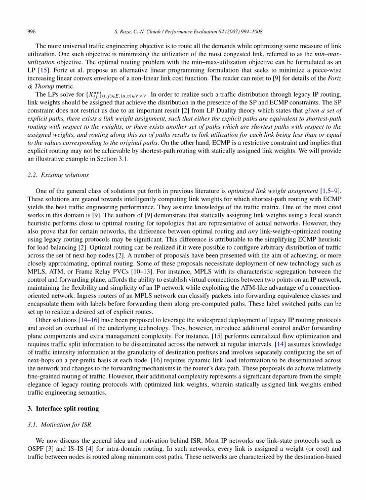
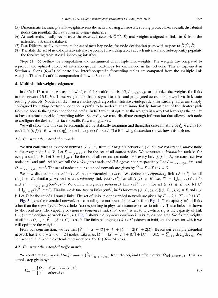
Fig. 3 gives the extended network corresponding to our example network from Fig. 1. The capacity of all linksother than the capacity bottleneck links (corresponding to physical resources) is set to infinity. These links are shownby the solid arcs. The capacity of capacity bottleneck link (ini j , outi j ) is set to ci j , where ci j is the capacity of link(i, j) in the original network G(V, E). Fig. 3 shows the capacity bottleneck links by dashed arcs. We fix the weightsof all links (i, j) ∈ E − (S′
∪ X ′) to be 0. The links belonging to S′∪ X ′ (shown in bold) are the ones for which we
will optimize the weights.From our construction, we see that |V | = |S| + |T | + |I | + |O| = 2|V | + 2|E |. Hence our example extended
network has 2 × 6 + 2 × 6 = 24 nodes. Likewise, |E | = |S′| + |T ′
| + |C ′| + |X ′
| = 3|E | +∑
i∈V degiin degi
out. Wecan see that our example extended network has 3 × 6 + 6 = 24 links.
4.2. Construct the extended traffic matrix
We construct the extended traffic matrix Ωuv(u,v)∈V ×V from the original traffic matrix Ωuv(u,v)∈V ×V . This is asimple step given by:
Ωuv =
Ωi j if (u, v) = (si , t j )
0 otherwise.(3)
1000 S. Raza, C.-N. Chuah / Performance Evaluation 64 (2007) 994–1008
Fig. 3. Extended network.
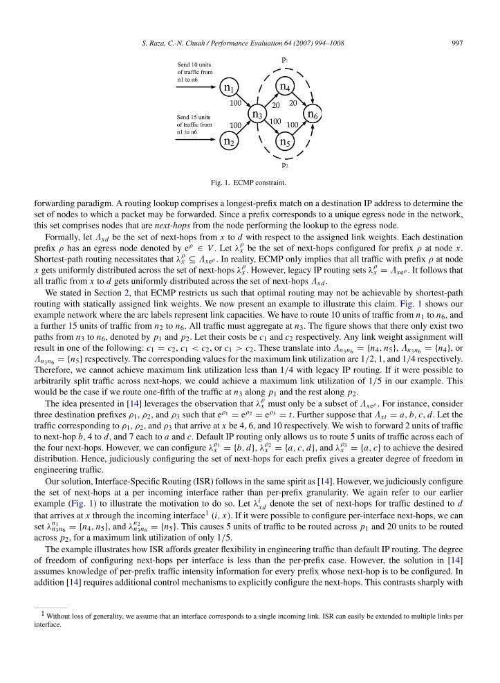
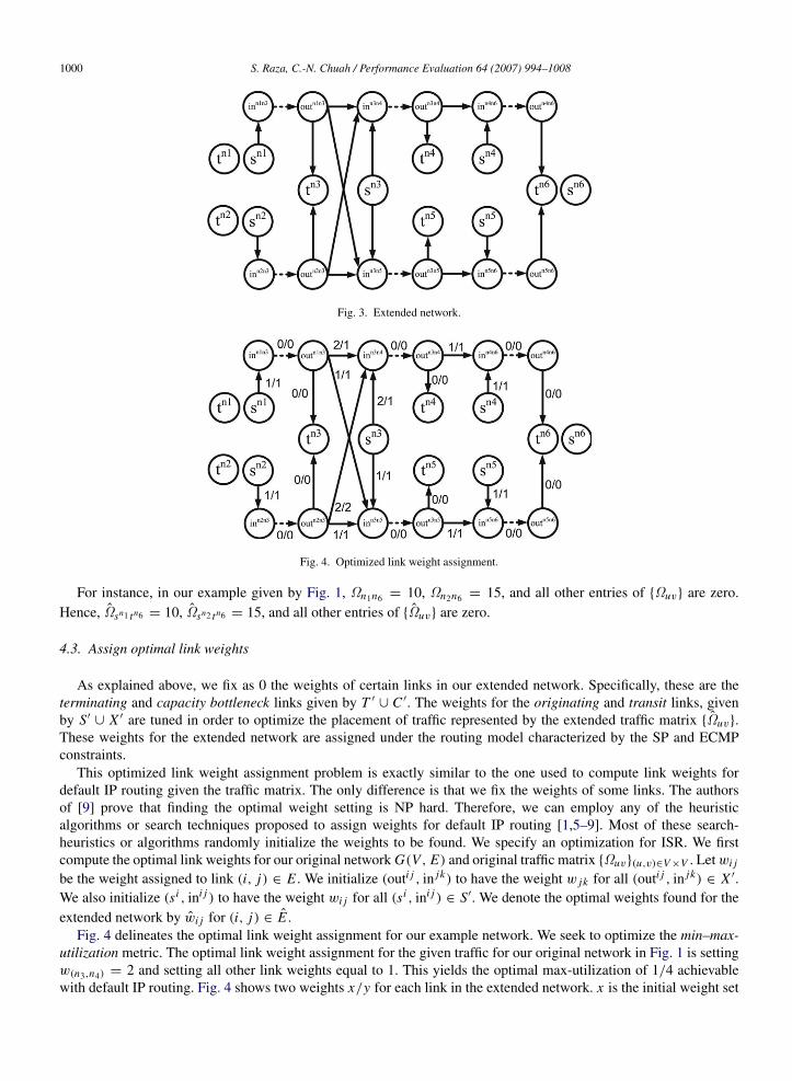
Fig. 4. Optimized link weight assignment.
For instance, in our example given by Fig. 1, Ωn1n6 = 10, Ωn2n6 = 15, and all other entries of Ωuv are zero.Hence, Ωsn1 tn6 = 10, Ωsn2 tn6 = 15, and all other entries of Ωuv are zero.
4.3. Assign optimal link weights
As explained above, we fix as 0 the weights of certain links in our extended network. Specifically, these are theterminating and capacity bottleneck links given by T ′
∪ C ′. The weights for the originating and transit links, givenby S′
∪ X ′ are tuned in order to optimize the placement of traffic represented by the extended traffic matrix Ωuv.These weights for the extended network are assigned under the routing model characterized by the SP and ECMPconstraints.
This optimized link weight assignment problem is exactly similar to the one used to compute link weights fordefault IP routing given the traffic matrix. The only difference is that we fix the weights of some links. The authorsof [9] prove that finding the optimal weight setting is NP hard. Therefore, we can employ any of the heuristicalgorithms or search techniques proposed to assign weights for default IP routing [1,5–9]. Most of these search-heuristics or algorithms randomly initialize the weights to be found. We specify an optimization for ISR. We firstcompute the optimal link weights for our original network G(V, E) and original traffic matrix Ωuv(u,v)∈V ×V . Let wi j
be the weight assigned to link (i, j) ∈ E . We initialize (outi j , in jk) to have the weight w jk for all (outi j , in jk) ∈ X ′.We also initialize (si , ini j ) to have the weight wi j for all (si , ini j ) ∈ S′. We denote the optimal weights found for theextended network by wi j for (i, j) ∈ E .
Fig. 4 delineates the optimal link weight assignment for our example network. We seek to optimize the min–max-utilization metric. The optimal link weight assignment for the given traffic for our original network in Fig. 1 is settingw(n3,n4) = 2 and setting all other link weights equal to 1. This yields the optimal max-utilization of 1/4 achievablewith default IP routing. Fig. 4 shows two weights x/y for each link in the extended network. x is the initial weight set
S. Raza, C.-N. Chuah / Performance Evaluation 64 (2007) 994–1008 1001
for a link derived from the solution for the original network and original traffic matrix. y is the optimized link weightwith respect to the extended traffic matrix. Observe that the optimized link weights with respect to the extendednetwork and extended traffic matrix yield a max-utilization of 1/5 in our example.
4.4. Assign multiple weights to links
The optimized link weights with respect to the extended network and extended traffic matrix constitute theinformation we require to configure interface-specific next-hop at network nodes. However, we want this informationto be made available to distributed network nodes by using existing link-state routing protocols. This is easilyaccomplished by modifying Link State Advertisements (LSAs) so that instead of having one weight for link (i, j) ∈ E ,we now have degi
in weights for (i, j) ∈ E . Therefore, every link has the following set of weights: Wi j = whi j |(h, i) ∈
E or h = j. The value of whi j is set as:
whi j =
wouthi ini j if (h, i) ∈ E and h 6= jwsi ini j if h = j (4)
whi j and wh
ik for h 6= j 6= k can be interpreted as signifying the relative preference of link (i, j) and (i, k) for trafficarriving at node i through node h. Also, wh
i j and wgi j for h 6= g 6= j can be interpreted as signifying the relative
preferability of link (i, j) by traffic arriving at node i through nodes h and g, respectively. Notice that we would neverwant to forward traffic arriving at node i through node j back to node j . We abuse the notation w
ji j to signify the
preferability of link (i, j) for traffic originating at node i .
5. Interface-specific forwarding tables
So far we have shown how, given the original network G(V, E) and the original traffic matrix Ωuv(u,v)∈V ×V ,we can compute a set of weights Wi j = wh
i j |(h, i) ∈ E or h = j for a link (i, j) ∈ E . We further claimed thatWi j (i, j)∈E holds all the information required to optimally configure the interface-specific forwarding tables at eachnode. This section explores how to do that.
A link-state routing protocol ensures that the link-state databases of a network node gets populated withWi j (i, j)∈E . The routing protocol also ensures that each node learns about the original topology G(V, E). Usingthe deterministic construction defined in Section 4.1, each node can reconstruct the extended network G(V , E).
Furthermore, we can also reconstruct the link weights that define our optimal solution for the extended networkand traffic matrix as follows:
wuv =
0 if (u, v) ∈ T ′
∪ C ′
whi j if (u, v) = (outhi , ini j )
wji j if (u, v) = (si , ini j ).
(5)
We now wish to compute the optimal interface-specific forwarding tables. We revert to our earlier definition fromSection 3.1 wherein λi
jd denotes the set of next-hops for traffic destined to d that arrives at j through the incominginterface (i, j). Note that i , j , and d are nodes in the original network and (i, j) is a link in the original network. LetΛ jd be the set of next-hops from j ∈ V to d ∈ V with respect to wuv(u,v)inE , in the extended network. The interfacespecific forwarding tables are configured as follows:
λijd =
k|in jk
∈ Λsi td i = jk|in jk
∈ Λouti j td otherwise.(6)
We use our example network to elucidate how interface-specific forwarding tables are configured. Consider noden3 in the original network. It has two incoming interfaces (n1, n3) and (n2, n3). In the extended network with optimalweights shown in Fig. 4, Λoutn1n3 tn6 = inn3n4 , inn3n5, and Λoutn2n3 tn6 = inn3n5. Therefore, λ
n1n3n6 = n4, n5, and
λn2n3n6 = n5. In other words, the set of next-hops at n3 to n6 for traffic arriving through n1 is n4, n5, and for traffic
arriving through n2 is n5. Looking at Fig. 1, this results in traffic arriving at n3 from n1 to be equally split acrossp1 and p2. Similarly, all the traffic arriving at n3 from n2 gets routed along p2. We, therefore, achieve a maximum
1002 S. Raza, C.-N. Chuah / Performance Evaluation 64 (2007) 994–1008
link utilization of 1/5, which is superior to that which could have been achieved through default IP routing. Sincewe initialize the link weights to correspond to the optimal weight setting for default IP routing, ISR is guaranteed toachieve performance that is equal to or better than default IP routing.
We defined Λ jd as the set of next-hops from j ∈ V to d ∈ V with respect to wuv(u,v)inE , in the extended network.
Λ jd is determined by computing Shortest-Path Trees (SPT) with respect to the extended network. Since the extendednetwork is larger than the original network, computing SPTs consumes greater CPU time. This can potentially meanthat nodes could take a longer time to converge to a consistent forwarding state upon failure. However, solutions existthat ensure prompt computation of SPTs from the structure of previous SPTs [18,19]. Such dynamic SPT computationlowers both the asymptotic complexities and the practical running times of the shortest-path computation. For instance,SPT computation only takes O(100 ms) for a network of more than 600 nodes [20]. Furthermore, since updating theforwarding engines constitutes the major bottleneck in convergence time [21], the extra computational overhead ofSPT is an acceptable cost.
Proof of Correctness
Correctness of our ISR implementation will demonstrate that optimizing the min–max-utilization and Fortz &Thorup metrics for G(V , E) with respect to Ωuv, results in optimizing the metrics for G(V, E) with respect toΩuv. Let χ be the set of i → j paths in G(V, E) and Υ be the set of si
→ t j paths in G(V , E), where i, j ∈ V . Wedefine a function R : Υ → χ , that maps each path in Υ to a corresponding path in χ . This function is represented bythe following:
R((s1, in12, out12, in23, out23, . . . , in(k−1)k, out(k−1)k, tk)) = (1, 2, 3, . . . , k − 1, k). (7)
As an example, consider the path ρ14 = (sn1 , inn1n3 , outn1n3 , inn3n4 , outn3n4 , tn4) in the extended network in Fig. 3.Then, R(ρ14) is given by the path (1, 3, 4). We further claim that R defines a 1:1 correspondence. This can be provedby observing that there are only four types of links in a si
→ t j path in G(V , E), where i, j ∈ V . These areoriginating links of the form (si , ini j ), terminating links of the form (outi j , t j ), capacity bottleneck links of the form(ini j , outi j ), and transit links of the form (outi j , in jk). From our construction of the extended network in 4.1, thefollowing is true:
(i, j) ∈ E ⇔ (si , ini j ) ∈ E (8)
(i, j) ∈ E ⇔ (outi j , t j ) ∈ E (9)
(i, j) ∈ E ⇔ (ini j , outi j ) ∈ E (10)
(i, j), ( j, k) ∈ E ⇔ (outi j , in jk) ∈ E . (11)
Therefore, there exists a unique path R(ρ) ∈ χ , ∀ρ ∈ Υ . Similarly, there exists a unique path R−1(ρ) ∈ Υ ,∀ρ ∈ χ .
Let ρ ∈ Υ be a path from si to td , and R(ρ) be given by ρ = (n1 = i, n2, n3, . . . ., nt = d). Consider only thetraffic between si to td on G(V , E), and between i to d on G(V, E). We claim that the amount of this traffic that arrivesat node n j through interface n j−1 is equal to the amount of traffic at outn j−1n j , for 1 < j ≤ t . We prove our claimby induction. We assume that the amount of traffic that arrives at n j through interface n j−1 is equal to the amount oftraffic at outn j−1n j . From Eq. (6) we know that inn j n j+1 ∈ Λoutn j−1n j nt
implies that n j+1 ∈ λn j−1n j nt . Also from Eq. (6),
we know that |Λoutn j−1n j nt| = |λ
n j−1n j nt |. ECMP implies that amount of traffic forwarded along (outn j−1n j , inn j n j+1)
is equal to the traffic forwarded along (n j , n j+1) that arrived at n j through n j−1. Since (inn j n j+1 , outn j n j+1) is theonly outgoing link from inn j n j+1, the amount of traffic that arrives at n j+1 through interface n j must be equal to theamount of traffic at outn j n j+1 . The basis is proved for j = 2, by noting that the traffic at sn1=i and n1 = i is thesame. This follows from Eq. (3) wherein Ωsi ,td = Ωid . Again from Eq. (6), we know inn1n2 ∈ Λsn1 nt implies thatn2 ∈ λ
n1n1nt . Also from Eq. (6), we know that |Λsn1 nt | = |λ
n1n1nt |. Hence, the same amount of traffic gets forwarded
along (sn1 , inn1n2) and (n1, n2). Since inn1n2 has only one outgoing link, it follows that the amount of traffic thatarrives at n2 through interface n1 must be equal to the amount of traffic at outn1n2 .
S. Raza, C.-N. Chuah / Performance Evaluation 64 (2007) 994–1008 1003
Fig. 5. Simulation network: ISP A.
Fig. 6. Simulation network: ISP B.
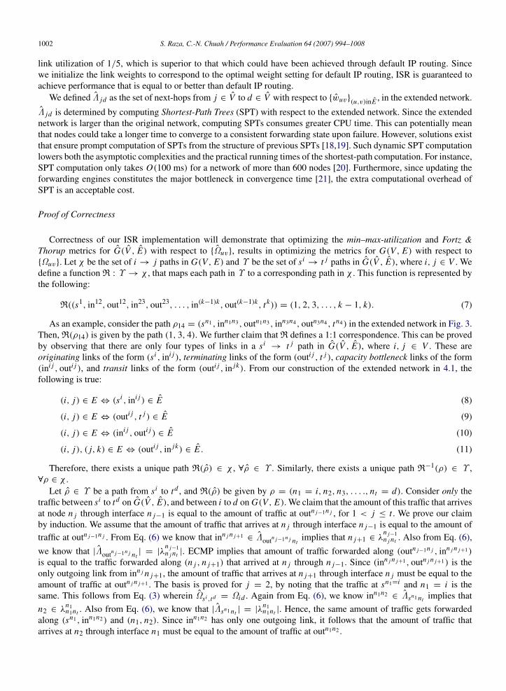
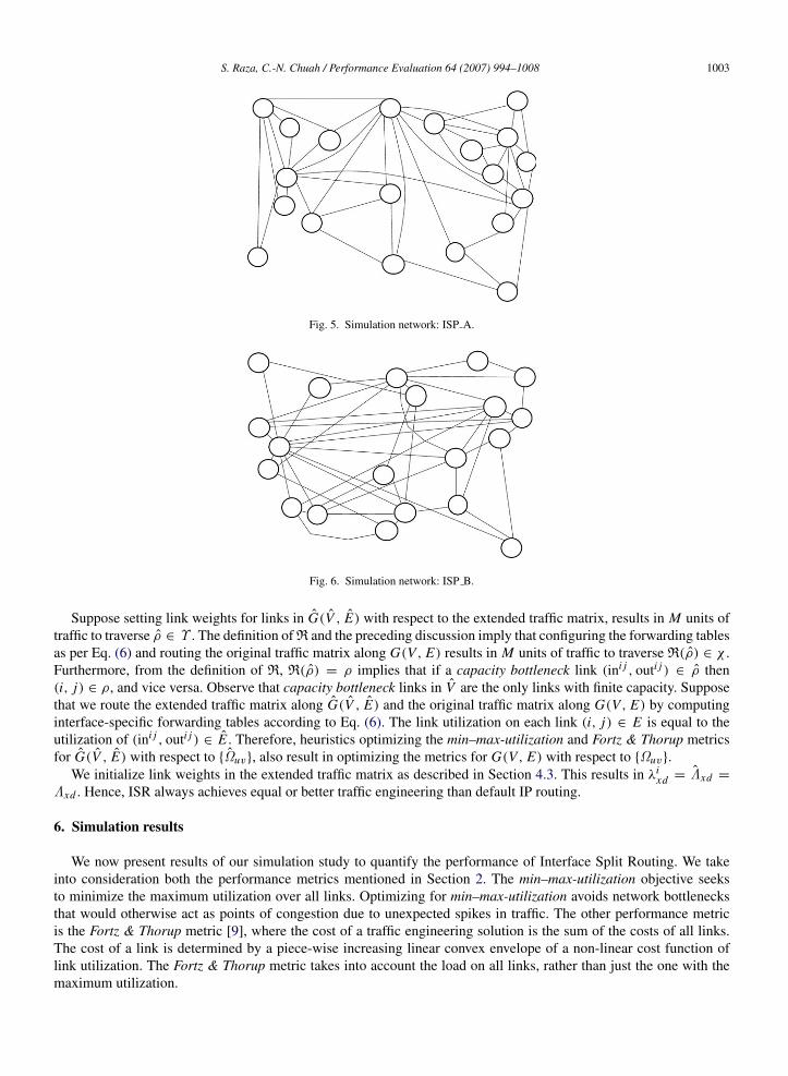
Suppose setting link weights for links in G(V , E) with respect to the extended traffic matrix, results in M units oftraffic to traverse ρ ∈ Υ . The definition of R and the preceding discussion imply that configuring the forwarding tablesas per Eq. (6) and routing the original traffic matrix along G(V, E) results in M units of traffic to traverse R(ρ) ∈ χ .Furthermore, from the definition of R, R(ρ) = ρ implies that if a capacity bottleneck link (ini j , outi j ) ∈ ρ then(i, j) ∈ ρ, and vice versa. Observe that capacity bottleneck links in V are the only links with finite capacity. Supposethat we route the extended traffic matrix along G(V , E) and the original traffic matrix along G(V, E) by computinginterface-specific forwarding tables according to Eq. (6). The link utilization on each link (i, j) ∈ E is equal to theutilization of (ini j , outi j ) ∈ E . Therefore, heuristics optimizing the min–max-utilization and Fortz & Thorup metricsfor G(V , E) with respect to Ωuv, also result in optimizing the metrics for G(V, E) with respect to Ωuv.
We initialize link weights in the extended traffic matrix as described in Section 4.3. This results in λixd = Λxd =
Λxd . Hence, ISR always achieves equal or better traffic engineering than default IP routing.
6. Simulation results
We now present results of our simulation study to quantify the performance of Interface Split Routing. We takeinto consideration both the performance metrics mentioned in Section 2. The min–max-utilization objective seeksto minimize the maximum utilization over all links. Optimizing for min–max-utilization avoids network bottlenecksthat would otherwise act as points of congestion due to unexpected spikes in traffic. The other performance metricis the Fortz & Thorup metric [9], where the cost of a traffic engineering solution is the sum of the costs of all links.The cost of a link is determined by a piece-wise increasing linear convex envelope of a non-linear cost function oflink utilization. The Fortz & Thorup metric takes into account the load on all links, rather than just the one with themaximum utilization.
1004 S. Raza, C.-N. Chuah / Performance Evaluation 64 (2007) 994–1008
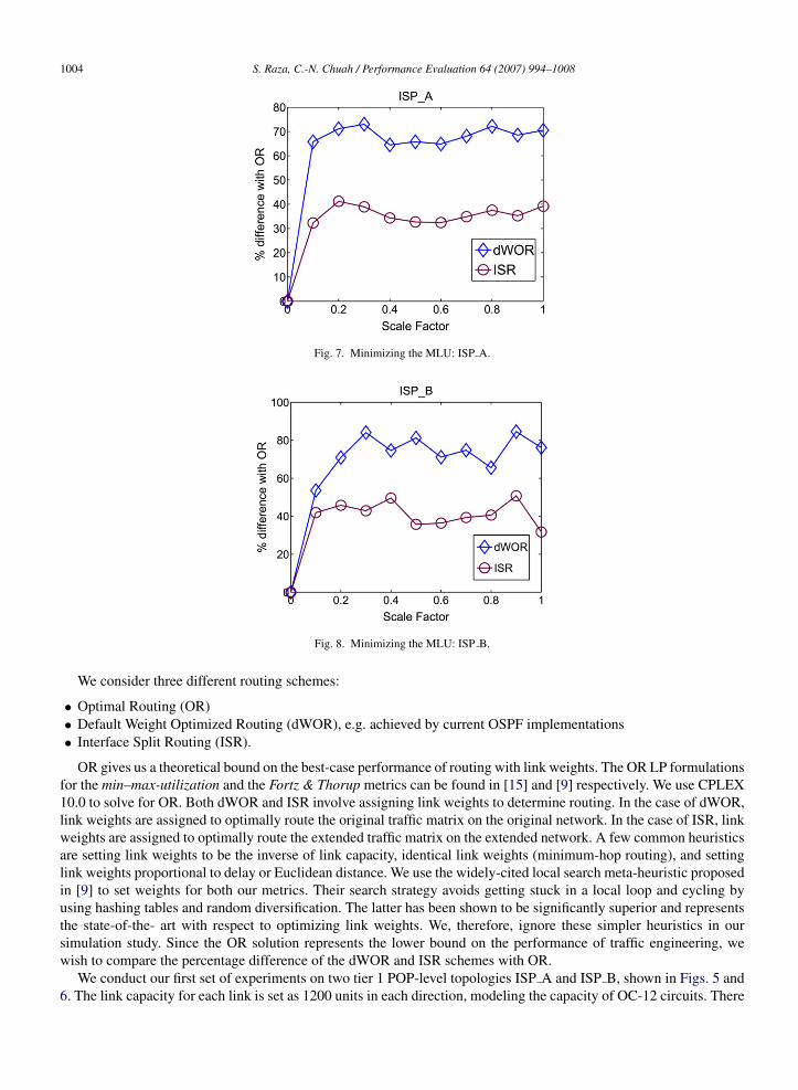
Fig. 7. Minimizing the MLU: ISP A.
Fig. 8. Minimizing the MLU: ISP B.
We consider three different routing schemes:
• Optimal Routing (OR)• Default Weight Optimized Routing (dWOR), e.g. achieved by current OSPF implementations• Interface Split Routing (ISR).
OR gives us a theoretical bound on the best-case performance of routing with link weights. The OR LP formulationsfor the min–max-utilization and the Fortz & Thorup metrics can be found in [15] and [9] respectively. We use CPLEX10.0 to solve for OR. Both dWOR and ISR involve assigning link weights to determine routing. In the case of dWOR,link weights are assigned to optimally route the original traffic matrix on the original network. In the case of ISR, linkweights are assigned to optimally route the extended traffic matrix on the extended network. A few common heuristicsare setting link weights to be the inverse of link capacity, identical link weights (minimum-hop routing), and settinglink weights proportional to delay or Euclidean distance. We use the widely-cited local search meta-heuristic proposedin [9] to set weights for both our metrics. Their search strategy avoids getting stuck in a local loop and cycling byusing hashing tables and random diversification. The latter has been shown to be significantly superior and representsthe state-of-the- art with respect to optimizing link weights. We, therefore, ignore these simpler heuristics in oursimulation study. Since the OR solution represents the lower bound on the performance of traffic engineering, wewish to compare the percentage difference of the dWOR and ISR schemes with OR.
We conduct our first set of experiments on two tier 1 POP-level topologies ISP A and ISP B, shown in Figs. 5 and6. The link capacity for each link is set as 1200 units in each direction, modeling the capacity of OC-12 circuits. There
S. Raza, C.-N. Chuah / Performance Evaluation 64 (2007) 994–1008 1005
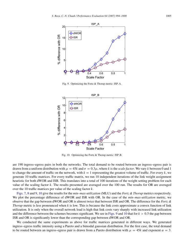
Fig. 9. Optimizing the Fortz & Thorup metric: ISP A.
Fig. 10. Optimizing the Fortz & Thorup metric: ISP B.
are 190 ingress–egress pairs in both the networks. The total demand to be routed between an ingress–egress pair isdrawn from a uniform distribution with µ = 45k and σ = 0.3µ, where k is the scale factor. We vary k between 0 and 1to change the amount of traffic on the network, with k = 1 representing the greatest volume of traffic. For every k, wegenerate 10 traffic matrices. For every traffic matrix, we run 10 independent iterations of the link weight assignmentheuristic for both dWOR and ISR. This translates into a total of 100 iterations of the weight setting problem for eachvalue of the scaling factor k. The results presented are averaged over the 100 run. The results for OR are averagedover the 10 traffic matrices per value of the scaling factor k.
Figs. 7, 8 and 9, 10 give the results for the min–max-utilization (MLU) and the Fortz & Thorup metrics respectively.We plot the percentage difference of dWOR and ISR with OR. In the case of the min–max-utilization metric, weobserve that the gap between dWOR and OR is almost twice that between ISR and OR. The difference for the Fortz &Thorup metric is less pronounced when k is low. This is because the link costs approximate a convex function of linkutilization. It is only when the overall network load is high that link costs vary sharply with increased link utilizationand the difference between the schemes becomes significant. We see in Figs. 9 and 10 that for k > 0.5 the gap betweenISR and OR is significantly lower than the corresponding gap between dWOR and OR.
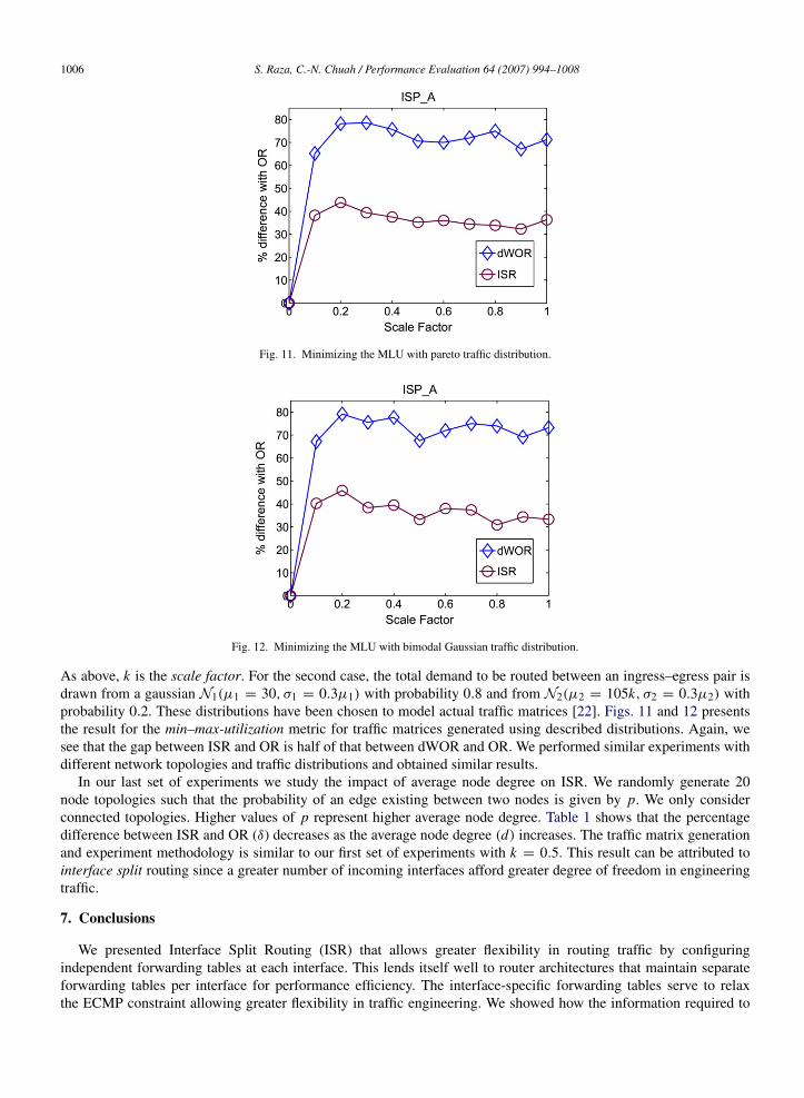
We conducted the same experiments as above for traffic matrices generated in different ways. We generatedingress–egress traffic intensity using a Pareto and a bimodal gaussian distribution. For the first case, the total demandto be routed between an ingress–egress pair is drawn from a Pareto distribution with µ = 45k and exponent α = 3.
1006 S. Raza, C.-N. Chuah / Performance Evaluation 64 (2007) 994–1008
Fig. 11. Minimizing the MLU with pareto traffic distribution.
Fig. 12. Minimizing the MLU with bimodal Gaussian traffic distribution.
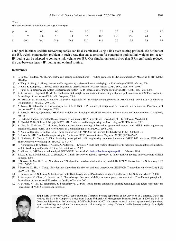
As above, k is the scale factor. For the second case, the total demand to be routed between an ingress–egress pair isdrawn from a gaussian N1(µ1 = 30, σ1 = 0.3µ1) with probability 0.8 and from N2(µ2 = 105k, σ2 = 0.3µ2) withprobability 0.2. These distributions have been chosen to model actual traffic matrices [22]. Figs. 11 and 12 presentsthe result for the min–max-utilization metric for traffic matrices generated using described distributions. Again, wesee that the gap between ISR and OR is half of that between dWOR and OR. We performed similar experiments withdifferent network topologies and traffic distributions and obtained similar results.
In our last set of experiments we study the impact of average node degree on ISR. We randomly generate 20node topologies such that the probability of an edge existing between two nodes is given by p. We only considerconnected topologies. Higher values of p represent higher average node degree. Table 1 shows that the percentagedifference between ISR and OR (δ) decreases as the average node degree (d) increases. The traffic matrix generationand experiment methodology is similar to our first set of experiments with k = 0.5. This result can be attributed tointerface split routing since a greater number of incoming interfaces afford greater degree of freedom in engineeringtraffic.
7. Conclusions
We presented Interface Split Routing (ISR) that allows greater flexibility in routing traffic by configuringindependent forwarding tables at each interface. This lends itself well to router architectures that maintain separateforwarding tables per interface for performance efficiency. The interface-specific forwarding tables serve to relaxthe ECMP constraint allowing greater flexibility in traffic engineering. We showed how the information required to
S. Raza, C.-N. Chuah / Performance Evaluation 64 (2007) 994–1008 1007
Table 1ISR performance as a function of average node degree
p 0.1 0.2 0.3 0.4 0.5 0.6 0.7 0.8 0.9 1.0
d 1.9 3.8 5.7 7.6 9.5 11.4 13.3 15.2 17.1 19
δ 30.2 29.5 28.9 26.9 21.2 14.9 5.7 2.7 2.8 2.5
configure interface-specific forwarding tables can be disseminated using a link-state routing protocol. We further setthe ISR weight computation problem in such a way that any algorithm for computing optimal link weights for legacyIP routing can be adapted to compute link weights for ISR. Our simulation results show that ISR significantly reducesthe gap between legacy IP routing and optimal routing.
References
[1] B. Fortz, J. Rexford, M. Thorup, Traffic engineering with traditional IP routing protocols, IEEE Communications Magazine 40 (10) (2002)118–124.
[2] Y. Wang, Z. Wang, L. Zhang, Internet traffic engineering without full mesh overlaying, in: Proceedings of IEEE Infocom, 2001.[3] D. Katz, K. Kompella, D. Yeung, Traffic engineering (TE) extensions to OSPF Version 2, RFC 3630, Tech. Rep., 2003.[4] H. Smit, T. Li, Intermediate system to intermediate system (IS–IS) extensions for traffic engineering, RFC 3784, Tech. Rep., 2004.[5] S. Srivastava, G. Agrawal, D. Medhi, Dual-based link weight determination towards single shortest path solutions for OSPF networks, in:
Proceedings of International Teletraffic Congress, 2005.[6] M. Ericsson, M. Resende, P. Pardalos, A genetic algorithm for the weight setting problem in OSPF routing, Journal of Combinatorial
Optimization 6 (3) (2002) 299–333.[7] A. Nucci, B. Schroeder, S. Bhattacharyya, N. Taft, C. Diot, IGP link weight assignment for transient link failures, in: Proceedings of
International Teletraffic Congress, 2003.[8] B. Fortz, M. Thorup, Optimizing OSPF/IS–IS weights in a changing world, IEEE Journal on Selected Areas in Communications 20 (4) (2002)
756–767.[9] B. Fortz, M. Thorup, Internet traffic engineering by optimizing OSPF weights, in: Proceedings of IEEE Infocom, March 2000.
[10] A. Elwalid, C. Jin, S. Low, I. Widjaja, MATE: MPLS adaptive traffic engineering, in: Proceedings of IEEE Infocom, 2001.[11] K. Kar, M. Kodialam, T. Lakshman, Minimum interference routing of bandwidth guaranteed tunnels with MPLS traffic engineering
applications, IEEE Journal on Selected Areas in Communication 18 (12) (2000) 2566–2579.[12] X. Xiao, A. Hannan, B. Bailey, L. Ni, Traffic engineering with MPLS in the Internet, IEEE Network 14 (2) (2000) 28–33.[13] D. Awduche, MPLS and traffic engineering in IP networks, IEEE Communications Magazine 37 (12) (1999) 42–47.[14] A. Sridharan, R. Guerin, C. Diot, Achieving near-optimal traffic engineering solutions for current OSPF/IS–IS networks, IEEE/ACM
Transactions on Networking 13 (2) (2005) 234–247.[15] H. Abrahamsson, B. Ahlgren, J. Alonso, A. Andersson, P. Kreuger, A multi path routing algorithm for IP networks based on flow optimisation,
in: Intl. Workshop on Quality of Future Internet Services, 2002.[16] C. Villamizar, OSPF optimized multipath OSPF-OMP. Internet-draft: draft-villamizar-ospf-omp-01.txt, February 1999.[17] S. Lee, Y. Yu, S. Nelakuditi, Z.-L. Zhang, C.-N. Chuah, Proactive vs reactive approaches to failure resilient routing, in: Proceedings of IEEE
Infocom, 2004.[18] P. Narvaez, K. Siu, H. Tzeng, New dynamic SPT algorithm based on a ball-and-string model, IEEE/ACM Transactions on Networking 9 (6)
(2001) 706–718.[19] P. Narvaez, K. Siu, H. Tzeng, New dynamic algorithms for shortest path tree computation, IEEE/ACM Transactions on Networking 8 (6)
(2000) 734–746.[20] G. Iannaccone, C.-N. Chuah, S. Bhattacharyya, C. Diot, Feasibility of IP restoration in a tier-1 backbone, IEEE Network (March) (2004).[21] R. Keralapura, C. Chuah, G. Iannaccone, S. Bhattacharyya, Service availability: A new approach to characterize IP backbone topologies, in:
Proceedings of International Workshop on Quality of Service, 2004.[22] A. Medina, N. Taft, K. Salamatian, S. Bhattacharyya, C. Diot, Traffic matrix estimation: Existing techniques and future directions, in:
Proceedings of ACM Sigcomm, August 2002.
Saqib Raza is currently a Ph.D. candidate in the Computer Science department at the University of California, Davis. Hereceived his B.Sc. in Computer Science from Lahore University of Management Sciences, Pakistan in 2004 and M.S. inComputer Science from the University of California, Davis in 2007. His current research interests span network algorithms,traffic engineering, network measurement, optimization, and graph theory. He has a specific interest in design & analysisof fault tolerant network systems.

1008 S. Raza, C.-N. Chuah / Performance Evaluation 64 (2007) 994–1008
Chen-Nee Chuah is currently an Associate Professor in the Electrical and Computer Engineering Department at theUniversity of California, Davis. She received her B.S. in Electrical Engineering from Rutgers University in 1995, andher M.S. and Ph.D. in Electrical Engineering and Computer Sciences from the University of California, Berkeley in1997 and 2001, respectively. Before joining UC Davis, she spent 9 months as a visiting researcher at Sprint AdvancedTechnology Laboratories. Her research interests lie in the area of computer networking and distributed systems, rangingfrom Internet measurements, overlay/peer-to-peer systems, network security, wireless/mobile networking, to opportunisticcommunications. She has published more than 70 research papers and received various awards and grants, including a NSFCAREER Award, an ACM Recognition of Service Award, and the UC Davis College of Engineering Outstanding JuniorFaculty Award.