Embed Size (px)
Citation preview
EMU Professional Modbus RTU/ACSII Specification
EMU Elektronik AG, Jöchlerweg 4 CH-6340 Baar File: EMU_Prof_ModBusRTU_ASCII_Specification_V00_e.doc
Date: 17.07.2012 Originator: Daniel KollerDocument type: Specification
Page 1 of 12
Interface specification
EMU Professional Modbus RTU/ASCII
Version Date of release Editor Description V0.0 17. Juli 2012 Daniel Koller First release
EMU Professional Modbus RTU/ACSII Specification
EMU Elektronik AG, Jöchlerweg 4 CH-6340 Baar File: EMU_Prof_ModBusRTU_ASCII_Specification_V00_e.doc
Date: 17.07.2012 Originator: Daniel KollerDocument type: Specification
Page 2 of 12
Contents
1 PURPOSE ......................................................................................................3
2 RESOURCEN ..................................................................................................3
3 MODBUS BASICS .............................................................................................3
4 MODBUS RTU ................................................................................................4
5 MODBUS ASCII ...............................................................................................4
6 MODBUS INTERFACE........................................................................................5
6.1 IMPLEMENTED FUNCTIONS ................................................................................... 5 6.2 READ HOLDING REGISTERS................................................................................... 6 6.3 REGISTER ADDRESSING ....................................................................................... 7 6.4 SYSTEM PARAMETER REGISTERS............................................................................... 7 6.5 DATA REGISTERS ............................................................................................ 8 6.6 DATA TYPES............................................................................................... 11 6.7 ERROR CODES............................................................................................. 11 6.8 EXAMPLE READOUT OF ACTIVE-ENERGY TARIFF 1 IMPORT ................................................... 12
EMU Professional Modbus RTU/ACSII Specification
EMU Elektronik AG, Jöchlerweg 4 CH-6340 Baar File: EMU_Prof_ModBusRTU_ASCII_Specification_V00_e.doc
Date: 17.07.2012 Originator: Daniel KollerDocument type: Specification
Page 3 of 12
1 Purpose Specification of the communication with the EMU Professional energy meter as a Modbus-Slave (server) over the Modbus RTU / ASCII Serial Line protocol.
2 Resourcen - Modbus over Serial Line Implemention Guide V1.02: http://www.modbus.org - Modbus Application Protocol Specification V1.1b: http://www.modbus.org
3 Modbus Basics The MODBUS Serial Line protocol is a Master-Slaves protocol. Only one master (at the same time) is connected to the bus, and one or several slaves nodes are also connected to the same serial bus. A MODBUS communication is always initiated by the master. The slave nodes will never transmit data without receiving a request from the master node. The slave nodes will never communicate with each other. The master node initiates only one MODBUS transaction at the same time.
The master node issues a MODBUS request to the slave nodes in two modes :
- In unicast mode, the master addresses an individual slave. After receiving and processing the request, the slave returns a message (a 'reply') to the master . In that mode, a MODBUS transaction consists of 2 messages : a request from the master, and a reply from the slave. Each slave must have an unique address (from 1 to 247) so that it can be addressed independently from other nodes.
- In broadcast mode, the master can send a request to all slaves. No response is returned to broadcast requests sent by the master. The broadcast requests are necessarily writing commands. All devices must accept the broadcast for writing function. The address 0 is reserved to identify a broadcast exchange.
Modbus Serial Line Frame :
Field 1
Address Field 2
Functi on-Code Field 3
Data Field 4
CRC / LRC
- Address : Slave address 1..247 or 0 for a broadcast - Function-Code : The function code indicates to the slave what kind of action to perform. - Data : Master: register address; Slave: the register contents - CRC / LRC : The redundancy check
The Function codes and the data is defined in the “Modbus Application Protocol Specification”.
Two different serial transmission modes are defined : The RTU mode and the ASCII mode. The transmission mode (and serial port parameters) must be the same for all devices on a MODBUS Serial Line.
EMU Professional Modbus RTU/ACSII Specification
EMU Elektronik AG, Jöchlerweg 4 CH-6340 Baar File: EMU_Prof_ModBusRTU_ASCII_Specification_V00_e.doc
Date: 17.07.2012 Originator: Daniel KollerDocument type: Specification
Page 4 of 12
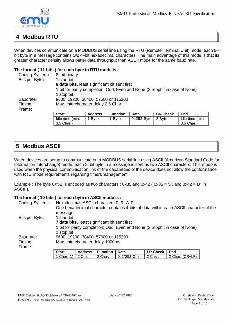
4 Modbus RTU
When devices communicate on a MODBUS serial line using the RTU (Remote Terminal Unit) mode, each 8–bit byte in a message contains two 4–bit hexadecimal characters. The main advantage of this mode is that its greater character density allows better data throughput than ASCII mode for the same baud rate.
The format ( 11 bits ) for each byte in RTU mode is :
Coding System: 8–bit binary Bits per Byte: 1 start bit
8 data bits, least significant bit sent first 1 bit for parity completion; Odd, Even and None (2.Stopbit in case of None) 1 stop bit
Baudrate: 9600, 19200, 38400, 57600 or 115200 Timing: Max. intercharacter delay 2,5 Char. Frame:
Start Address Function Data CR-Check End Idle time (min. 3.5 Char.)
1 Byte 1 Byte 0..252 Byte 2 Byte Idle time (min. 3.5 Char.)
5 Modbus ASCII
When devices are setup to communicate on a MODBUS serial line using ASCII (American Standard Code for Information Interchange) mode, each 8–bit byte in a message is sent as two ASCII characters. This mode is used when the physical communication link or the capabilities of the device does not allow the conformance with RTU mode requirements regarding timers management. Example : The byte 0X5B is encoded as two characters : 0x35 and 0x42 ( 0x35 ="5", and 0x42 ="B" in ASCII ).
The format ( 10 bits ) for each byte in ASCII mode is :
Coding System: Hexadecimal, ASCII characters 0–9, A–F One hexadecimal character contains 4-bits of data within each ASCII character of the message
Bits per Byte: 1 start bit 7 data bits, least significant bit sent first 1 bit for parity completion; Odd, Even and None (2.Stopbit in case of None) 1 stop bit
Baudrate: 9600, 19200, 38400, 57600 or 115200 Timing: Max. intercharacter delay 1000ms Frame:
Start Address Function Data LR-Check End 1 Char. (:) 2 Char. 2 Char. 0..2*252 Char. 2 Char. 2 Char. (CR+LF)
EMU Professional Modbus RTU/ACSII Specification
EMU Elektronik AG, Jöchlerweg 4 CH-6340 Baar File: EMU_Prof_ModBusRTU_ASCII_Specification_V00_e.doc
Date: 17.07.2012 Originator: Daniel KollerDocument type: Specification
Page 5 of 12
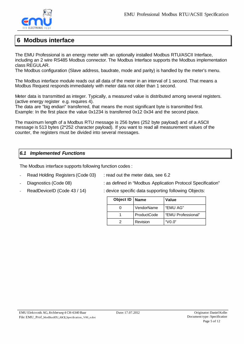
6 Modbus interface
The EMU Professional is an energy meter with an optionally installed Modbus RTU/ASCII Interface, including an 2 wire RS485 Modbus connector. The Modbus Interface supports the Modbus implementation class REGULAR. The Modbus configuration (Slave address, baudrate, mode and parity) is handled by the meter’s menu. The Modbus interface module reads out all data of the meter in an interval of 1 second. That means a Modbus Request responds immediately with meter data not older than 1 second. Meter data is transmitted as integer. Typically, a measured value is distributed among several registers. (active energy register e.g. requires 4). The data are "big endian" transferred, that means the most significant byte is transmitted first. Example: In the first place the value 0x1234 is transferred 0x12 0x34 and the second place. The maximum length of a Modbus RTU message is 256 bytes (252 byte payload) and of a ASCII message is 513 bytes (2*252 character payload). If you want to read all measurement values of the counter, the registers must be divided into several messages.
6.1 Implemented Functions
The Modbus interface supports following function codes :
- Read Holding Registers (Code 03) : read out the meter data, see 6.2
- Diagnostics (Code 08) : as defined in “Modbus Application Protocol Specification”
- ReadDeviceID (Code 43 / 14) : device specific data supporting following Objects:
Object ID Name Value
0 VendorName “EMU AG”
1 ProductCode “EMU Professional”
2 Revision “V0.0”
EMU Professional Modbus RTU/ACSII Specification
EMU Elektronik AG, Jöchlerweg 4 CH-6340 Baar File: EMU_Prof_ModBusRTU_ASCII_Specification_V00_e.doc
Date: 17.07.2012 Originator: Daniel KollerDocument type: Specification
Page 6 of 12
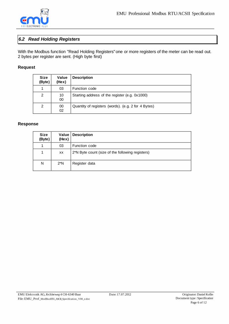
6.2 Read Holding Registers
With the Modbus function "Read Holding Registers" one or more registers of the meter can be read out. 2 bytes per register are sent. (High byte first)
Request
Size (Byte)
Value (Hex)
Description
1 03 Function code 2 10
00 Starting address of the register (e.g. 0x1000)
2 00 02
Quantity of registers (words). (e.g. 2 for 4 Bytes)
Response
Size (Byte)
Value (Hex)
Description
1 03 Function code 1 xx 2*N Byte count (size of the following registers)
N 2*N Register data
EMU Professional Modbus RTU/ACSII Specification
EMU Elektronik AG, Jöchlerweg 4 CH-6340 Baar File: EMU_Prof_ModBusRTU_ASCII_Specification_V00_e.doc
Date: 17.07.2012 Originator: Daniel KollerDocument type: Specification
Page 7 of 12
6.3 Register addressing
The register starting address in the Modbus protocol defines the meters first register to address. For historical reasons, the starting address of the register starts at 1, but the start address in Modbus starts with 0. This means that in the telegram as a starting Modbus register address is the address minus 1.
Example:
Momentary system time (4200) will be send as Modbus start address 4199.
6.4 System parameter registers
System Parameter Modbus RTU/ASCII Interface
Register (Hex)
Name Size (Byte)
Description
4108 Software Version 2 Software Version of the Modbus interface firmware
System Parameter Meter
Register (Hex)
Name Size (Byte)
Description
4109 Meter Serial number 4 Serial number of the meter 4111 Software Version and
Checksum 4 Software Version and Checksum of the meters
firmware
EMU Professional Modbus RTU/ACSII Specification
EMU Elektronik AG, Jöchlerweg 4 CH-6340 Baar File: EMU_Prof_ModBusRTU_ASCII_Specification_V00_e.doc
Date: 17.07.2012 Originator: Daniel KollerDocument type: Specification
Page 8 of 12
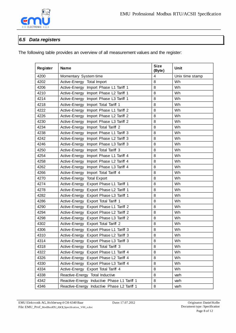
6.5 Data registers
The following table provides an overview of all measurement values and the register:
Register
Name Size
(Byte) Unit
4200 Momentary System time 4 Unix time stamp 4202 Active-Energy Total Import 8 Wh 4206 Active-Energy Import Phase L1 Tariff 1 8 Wh 4210 Active-Energy Import Phase L2 Tariff 1 8 Wh 4214 Active-Energy Import Phase L3 Tariff 1 8 Wh 4218 Active-Energy Import Total Tariff 1 8 Wh 4222 Active-Energy Import Phase L1 Tariff 2 8 Wh 4226 Active-Energy Import Phase L2 Tariff 2 8 Wh 4230 Active-Energy Import Phase L3 Tariff 2 8 Wh 4234 Active-Energy Import Total Tariff 2 8 Wh 4238 Active-Energy Import Phase L1 Tariff 3 8 Wh 4242 Active-Energy Import Phase L2 Tariff 3 8 Wh 4246 Active-Energy Import Phase L3 Tariff 3 8 Wh 4250 Active-Energy Import Total Tariff 3 8 Wh 4254 Active-Energy Import Phase L1 Tariff 4 8 Wh 4258 Active-Energy Import Phase L2 Tariff 4 8 Wh 4262 Active-Energy Import Phase L3 Tariff 4 8 Wh 4266 Active-Energy Import Total Tariff 4 8 Wh 4270 Active-Energy Total Export 8 Wh 4274 Active-Energy Export Phase L1 Tariff 1 8 Wh 4278 Active-Energy Export Phase L2 Tariff 1 8 Wh 4282 Active-Energy Export Phase L3 Tariff 1 8 Wh 4286 Active-Energy Export Total Tariff 1 8 Wh 4290 Active-Energy Export Phase L1 Tariff 2 8 Wh 4294 Active-Energy Export Phase L2 Tariff 2 8 Wh 4298 Active-Energy Export Phase L3 Tariff 2 8 Wh 4302 Active-Energy Export Total Tariff 2 8 Wh 4306 Active-Energy Export Phase L1 Tariff 3 8 Wh 4310 Active-Energy Export Phase L2 Tariff 3 8 Wh 4314 Active-Energy Export Phase L3 Tariff 3 8 Wh 4318 Active-Energy Export Total Tariff 3 8 Wh 4322 Active-Energy Export Phase L1 Tariff 4 8 Wh 4326 Active-Energy Export Phase L2 Tariff 4 8 Wh 4330 Active-Energy Export Phase L3 Tariff 4 8 Wh 4334 Active-Energy Export Total Tariff 4 8 Wh 4338 Reactive-Energy Total Inductive 8 varh 4342 Reactive-Energy Inductive Phase L1 Tariff 1 8 varh 4346 Reactive-Energy Inductive Phase L2 Tariff 1 8 varh
EMU Professional Modbus RTU/ACSII Specification
EMU Elektronik AG, Jöchlerweg 4 CH-6340 Baar File: EMU_Prof_ModBusRTU_ASCII_Specification_V00_e.doc
Date: 17.07.2012 Originator: Daniel KollerDocument type: Specification
Page 9 of 12
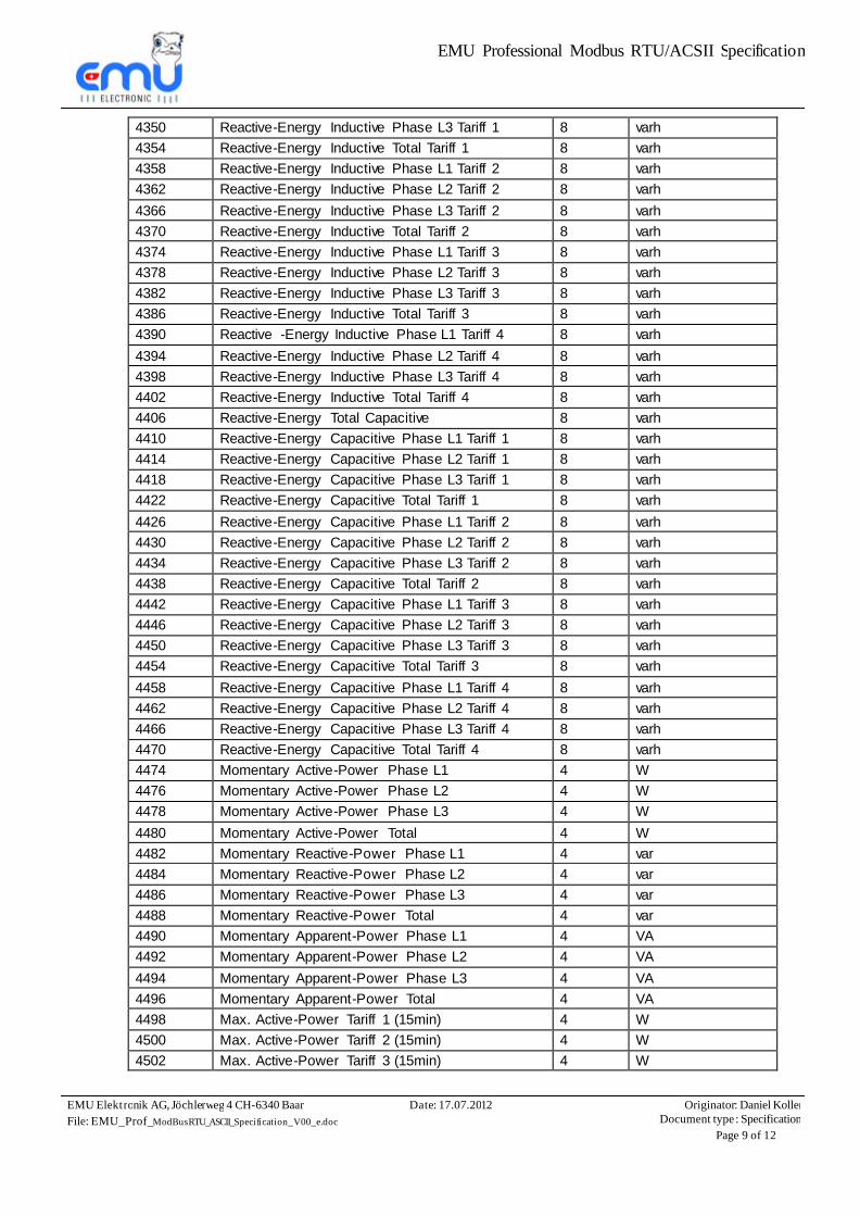
4350 Reactive-Energy Inductive Phase L3 Tariff 1 8 varh 4354 Reactive-Energy Inductive Total Tariff 1 8 varh 4358 Reactive-Energy Inductive Phase L1 Tariff 2 8 varh 4362 Reactive-Energy Inductive Phase L2 Tariff 2 8 varh 4366 Reactive-Energy Inductive Phase L3 Tariff 2 8 varh 4370 Reactive-Energy Inductive Total Tariff 2 8 varh 4374 Reactive-Energy Inductive Phase L1 Tariff 3 8 varh 4378 Reactive-Energy Inductive Phase L2 Tariff 3 8 varh 4382 Reactive-Energy Inductive Phase L3 Tariff 3 8 varh 4386 Reactive-Energy Inductive Total Tariff 3 8 varh 4390 Reactive -Energy Inductive Phase L1 Tariff 4 8 varh 4394 Reactive-Energy Inductive Phase L2 Tariff 4 8 varh 4398 Reactive-Energy Inductive Phase L3 Tariff 4 8 varh 4402 Reactive-Energy Inductive Total Tariff 4 8 varh 4406 Reactive-Energy Total Capacitive 8 varh 4410 Reactive-Energy Capacitive Phase L1 Tariff 1 8 varh 4414 Reactive-Energy Capacitive Phase L2 Tariff 1 8 varh 4418 Reactive-Energy Capacitive Phase L3 Tariff 1 8 varh 4422 Reactive-Energy Capacitive Total Tariff 1 8 varh 4426 Reactive-Energy Capacitive Phase L1 Tariff 2 8 varh 4430 Reactive-Energy Capacitive Phase L2 Tariff 2 8 varh 4434 Reactive-Energy Capacitive Phase L3 Tariff 2 8 varh 4438 Reactive-Energy Capacitive Total Tariff 2 8 varh 4442 Reactive-Energy Capacitive Phase L1 Tariff 3 8 varh 4446 Reactive-Energy Capacitive Phase L2 Tariff 3 8 varh 4450 Reactive-Energy Capacitive Phase L3 Tariff 3 8 varh 4454 Reactive-Energy Capacitive Total Tariff 3 8 varh 4458 Reactive-Energy Capacitive Phase L1 Tariff 4 8 varh 4462 Reactive-Energy Capacitive Phase L2 Tariff 4 8 varh 4466 Reactive-Energy Capacitive Phase L3 Tariff 4 8 varh 4470 Reactive-Energy Capacitive Total Tariff 4 8 varh 4474 Momentary Active-Power Phase L1 4 W 4476 Momentary Active-Power Phase L2 4 W 4478 Momentary Active-Power Phase L3 4 W 4480 Momentary Active-Power Total 4 W 4482 Momentary Reactive-Power Phase L1 4 var 4484 Momentary Reactive-Power Phase L2 4 var 4486 Momentary Reactive-Power Phase L3 4 var 4488 Momentary Reactive-Power Total 4 var 4490 Momentary Apparent-Power Phase L1 4 VA 4492 Momentary Apparent-Power Phase L2 4 VA 4494 Momentary Apparent-Power Phase L3 4 VA 4496 Momentary Apparent-Power Total 4 VA 4498 Max. Active-Power Tariff 1 (15min) 4 W 4500 Max. Active-Power Tariff 2 (15min) 4 W 4502 Max. Active-Power Tariff 3 (15min) 4 W
EMU Professional Modbus RTU/ACSII Specification
EMU Elektronik AG, Jöchlerweg 4 CH-6340 Baar File: EMU_Prof_ModBusRTU_ASCII_Specification_V00_e.doc
Date: 17.07.2012 Originator: Daniel KollerDocument type: Specification
Page 10 of 12
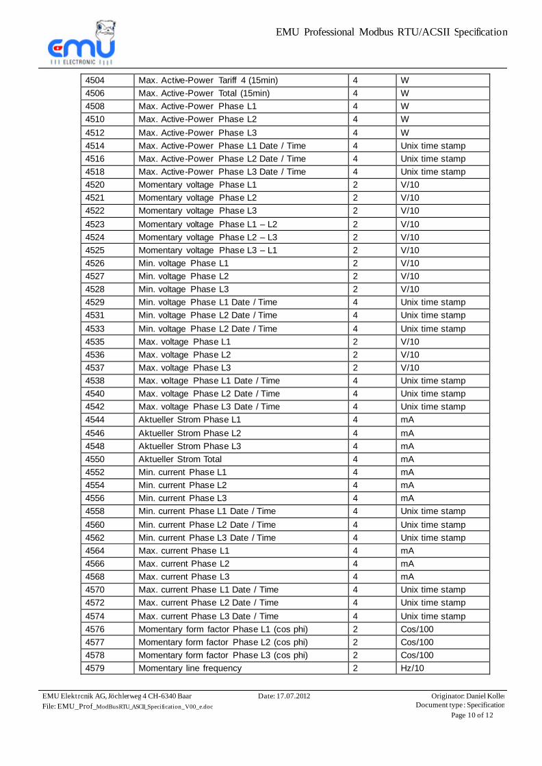
4504 Max. Active-Power Tariff 4 (15min) 4 W 4506 Max. Active-Power Total (15min) 4 W 4508 Max. Active-Power Phase L1 4 W 4510 Max. Active-Power Phase L2 4 W 4512 Max. Active-Power Phase L3 4 W 4514 Max. Active-Power Phase L1 Date / Time 4 Unix time stamp 4516 Max. Active-Power Phase L2 Date / Time 4 Unix time stamp 4518 Max. Active-Power Phase L3 Date / Time 4 Unix time stamp 4520 Momentary voltage Phase L1 2 V/10 4521 Momentary voltage Phase L2 2 V/10 4522 Momentary voltage Phase L3 2 V/10 4523 Momentary voltage Phase L1 – L2 2 V/10 4524 Momentary voltage Phase L2 – L3 2 V/10 4525 Momentary voltage Phase L3 – L1 2 V/10 4526 Min. voltage Phase L1 2 V/10 4527 Min. voltage Phase L2 2 V/10 4528 Min. voltage Phase L3 2 V/10 4529 Min. voltage Phase L1 Date / Time 4 Unix time stamp 4531 Min. voltage Phase L2 Date / Time 4 Unix time stamp 4533 Min. voltage Phase L2 Date / Time 4 Unix time stamp 4535 Max. voltage Phase L1 2 V/10 4536 Max. voltage Phase L2 2 V/10 4537 Max. voltage Phase L3 2 V/10 4538 Max. voltage Phase L1 Date / Time 4 Unix time stamp 4540 Max. voltage Phase L2 Date / Time 4 Unix time stamp 4542 Max. voltage Phase L3 Date / Time 4 Unix time stamp 4544 Aktueller Strom Phase L1 4 mA 4546 Aktueller Strom Phase L2 4 mA 4548 Aktueller Strom Phase L3 4 mA 4550 Aktueller Strom Total 4 mA 4552 Min. current Phase L1 4 mA 4554 Min. current Phase L2 4 mA 4556 Min. current Phase L3 4 mA 4558 Min. current Phase L1 Date / Time 4 Unix time stamp 4560 Min. current Phase L2 Date / Time 4 Unix time stamp 4562 Min. current Phase L3 Date / Time 4 Unix time stamp 4564 Max. current Phase L1 4 mA 4566 Max. current Phase L2 4 mA 4568 Max. current Phase L3 4 mA 4570 Max. current Phase L1 Date / Time 4 Unix time stamp 4572 Max. current Phase L2 Date / Time 4 Unix time stamp 4574 Max. current Phase L3 Date / Time 4 Unix time stamp 4576 Momentary form factor Phase L1 (cos phi) 2 Cos/100 4577 Momentary form factor Phase L2 (cos phi) 2 Cos/100 4578 Momentary form factor Phase L3 (cos phi) 2 Cos/100 4579 Momentary line frequency 2 Hz/10
EMU Professional Modbus RTU/ACSII Specification
EMU Elektronik AG, Jöchlerweg 4 CH-6340 Baar File: EMU_Prof_ModBusRTU_ASCII_Specification_V00_e.doc
Date: 17.07.2012 Originator: Daniel KollerDocument type: Specification
Page 11 of 12
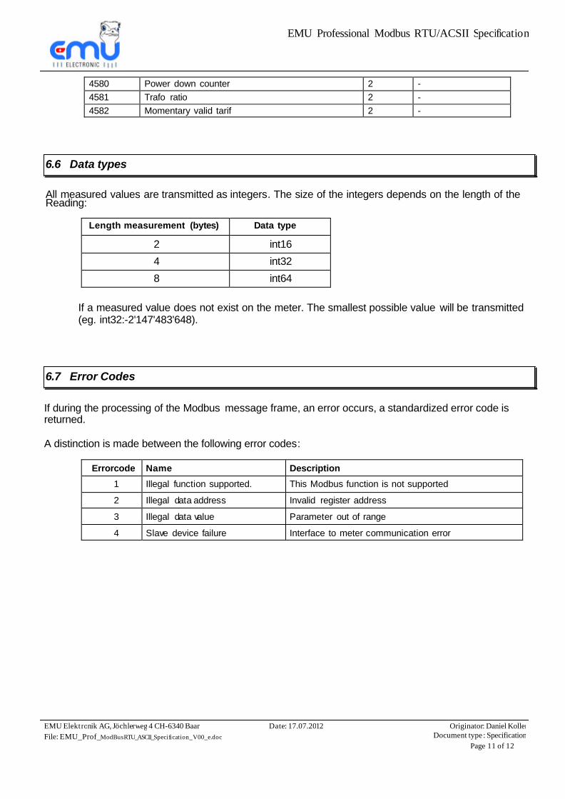
4580 Power down counter 2 - 4581 Trafo ratio 2 - 4582 Momentary valid tarif 2 -
6.6 Data types
All measured values are transmitted as integers. The size of the integers depends on the length of the Reading:
Length measurement (bytes) Data type
2 int16 4 int32 8 int64
If a measured value does not exist on the meter. The smallest possible value will be transmitted (eg. int32:-2'147'483'648).
6.7 Error Codes
If during the processing of the Modbus message frame, an error occurs, a standardized error code is returned. A distinction is made between the following error codes:
Errorcode Name Description
1 Illegal function supported. This Modbus function is not supported 2 Illegal data address Invalid register address 3 Illegal data value Parameter out of range 4 Slave device failure Interface to meter communication error
EMU Professional Modbus RTU/ACSII Specification
EMU Elektronik AG, Jöchlerweg 4 CH-6340 Baar File: EMU_Prof_ModBusRTU_ASCII_Specification_V00_e.doc
Date: 17.07.2012 Originator: Daniel KollerDocument type: Specification
Page 12 of 12
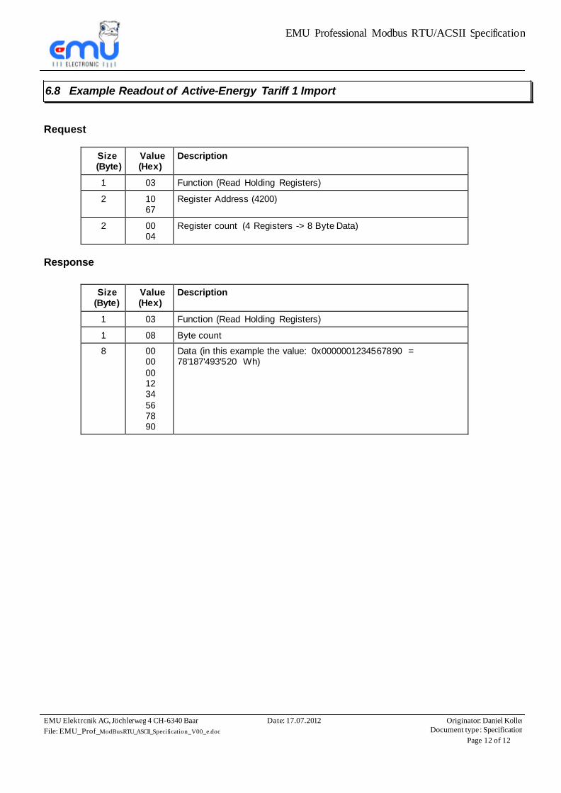
6.8 Example Readout of Active-Energy Tariff 1 Import
Request
Size (Byte)
Value (Hex)
Description
1 03 Function (Read Holding Registers) 2 10
67 Register Address (4200)
2 00 04
Register count (4 Registers -> 8 Byte Data)
Response
Size (Byte)
Value (Hex)
Description
1 03 Function (Read Holding Registers) 1 08 Byte count 8 00
00 00 12 34 56 78 90
Data (in this example the value: 0x0000001234567890 = 78'187'493'520 Wh)


![êÞ^ÞçéÖ] m`jÖ]íuæ† æäèçfé‰ ﻮﺑﻭﺮﺗ …ˇ ˆ˙ êÞ^ÞçéÖ] m`jÖ]íuæ† _æäèçfé‰ "ﻮﺑﻭﺮﺗ ﺭﺍﺮﻴﺟ "ﺪﻨﻋ ﻲﺑﺮﻌﻟﺍ](https://img.pdfslide.us/doc/110x75/5e47d1a842268c23f4598e25/-mjua-fa-iiiii-.jpg)