Embed Size (px)
Citation preview

1
Interface card deVIcenet fOr thyrO-P and thyrO-P Mc
July 2014 de/en - V3
2
1. Introduction 7
1.1 General 7
1.2 Specific characteristics 7
1.3 type designation 8
1.4 Warranty 8
2. Safety 9
2.1 Identification in the operating instructions 9
2.2 General danger information 10
2.3 Operator requirements 11
2.4 Personnel requirements 11
2.5 Intended purpose 11
2.6 Use of the device 12
2.6.1 Operation 12
2.6.2 Prior to installation / start-up 12
2.6.3 Maintenance, service, faults 12
2.6.4 transport 13
3. Installation & Setup 14
3.1 Installation 14
3.2 Setup the address 14
3.3 Setup the communication speed 14
3.4 connection 14
3.5 controller setup 15
4. Object specifications 16
4.1 0x01 Identity Object 16
4.2 0x02 Message router Object 17
4.3 0x03 devicenet Object 17
4.4 0x04 assembly Object 18
4.5 0x05 connection Object 19
4.6 0x0f Parameter Object 21
4.7 0x64-0x66 Vendor Specific Object 22
table Of cOntentS

3
5. Status leds 24
6. digital Inputs 26
7. local operation of the Setpoint Motorpoti 28
8. assembly 31
8.1 assembly 101: Setpoint (Output for Poll) 31
8.2 assembly 102: Setpoint, State… (Input for Poll) 32
8.3 assembly 103: actual value thyro-P 1P 33
8.4 assembly 104: actual value thyro-P 2P 34
8.5 assembly 105: actual value thyro-P 3P 34
8.6 assembly 106: Other actual value 35
9. attributes 36
9.1 attributes of class 0x64 36
9.2 attributes of class 0x65 39
9.3 attributes of class 0x66 41
10. technical specifications 46

4
fig. 1.1 devicenet interface card 7fig. 3.1 Wiring connection 15fig. 6.2 example of connecting inputs 27fig. 7.1 relative changing of the motorpoti setpoint over the time 28fig. 7.2 local operation of the setpoint motorpoti 29fig. 7.3 State diagram 30
tab. 4.1 Identity Object class attributes 16tab. 4.2 Identity Object Instance attributes 16tab. 4.3 Identity Object Services 17tab. 4.4 devicenet Object class attributes 17tab. 4.5 devicenet Object Instance attributes 17tab. 4.6 devicenet Object Services 18tab. 4.7 assembly Object class attributes 18tab. 4.8 assembly Object Instance attributes 18tab. 4.9 assembly Object Services 19tab. 4.10 connection class Instances 19tab. 4.11 connection class attributes 19tab. 4.12 connection class Instance attributes 20tab. 4.13 connection class Services 21tab. 4.14 Parameter class attributes 21tab. 4.15 Parameter class Services 22tab. 4.16 thyro-P attributes 22tab. 4.17 Vendor specific Objects class attributes 23tab. 4.18 Vendor specific Object Services 23tab. 5.1 Module Status led 24tab. 5.2 network Status led 25tab. 6.1 connection assignment X21 26tab. 8.1 Output assembly 101 31tab. 8.2 description of the configuration byte 31tab. 8.3 Input assembly 102 32tab. 8.4 led & relays state 32tab. 8.5 digital Input 32tab. 8.6 thyro-P state 33tab. 8.7 Setpoint active 33tab. 8.8 Input assembly 103 33tab. 8.9 Input assembly 104 34
lISt Of IllUStratIOnS and tableS

5
tab. 8.10 Input assembly 105 34tab. 8.11 Input assembly 106 35tab. 9.1 Setpoints 36tab. 9.2 actual values 37tab. 9.3 functions 37tab. 9.4 hardware 38tab. 9.5 Operating mode 39tab. 9.6 times 39tab. 9.7 controls 40tab. 9.8 limit 40tab. 9.9 control characteristic 41tab. 9.10 temperature 41tab. 9.11 analog outputs 42tab. 9.12 Monitoring 43tab. 9.13 led & relays 44tab. 9.14 Miscellaneous 45

6
cOntact
technIcal qUerIeSdo you have any technical queries regarding the subjects dealt with inthese operating instructions?If so, please get in touch with our team for power controllers:Phone +49 (0) 2902 763-520
cOMMercIal qUerIeSdo you have any commercial queries on power controllers?If so, please get in touch with our team for power controllers.Phone +49 (0) 2902 763-558
SerVIceadvanced energy Industries Gmbhbranch Office Warstein-beleckeemil-Siepmann-Straße 32d-59581 WarsteinPhone +49 (0) 2902 763-0http://www.advanced-energy.com
cOPyrIGhtno part of these operating instructions may be transmitted, reproduced and/or copied by any electronic or mechanical means without the express prior written permission of advanced energy.© copyright advanced energy Industries Gmbh 2014.all rights reserved.
fUrther InfOrMatIOn On cOPyrIGhtthyro-™, thyro-P™ are registered trademark of advanced energy Industries Gmbh. all other company and product names are (registered) trademarks of the respective owners.

7
1. IntrOdUctIOn
1.1 Generalthis communications card adds the devicenet communications interface to the thyro-P (thyristor power controller). It can be used for integrating the thyro-P into complex systems using the fieldbus. In addition, there are 4 digital electrically isolated inputs on the card (see section 6). these can be accessed via terminal X21.
1.2 SPecIfIc characterIStIcSthe scope of delivery includes:- a devicenet interface card- a cover for installing in the thyro-P- a diskette containing the files needed for project planning- these instructionsthe devicenet connection uses a 5-pin Open connector (X20). It provides the standard connection for devicenet. the devicenet card needs 80 ma from the 24V supply.
fIG. 1.1 deVIcenet Interface card
X20
leds
X21
X24

8
1.3 tyPe deSIGnatIOndevicenet interface card Order no. 2000 000 394corresponding GSd file 03f9000c00010200
1.4 WarrantyIn the event of any claims in connection with the devicenet interface card, please contact us immediately quoting:- type designation- Works number / Serial number- reason for the complaint- environmental conditions of the device- Operating mode- Period of useGoods and services are subject to the general conditions of supply forproducts of the electrical industry, and our general sales conditions.claims in connection with supplied goods must be submitted within one week of receipt, along with the delivery note. advanced energy will rescind all obligations such as warranty agreements, service contracts, etc. entered into by advanced energy or its representatives without prior notice if mainte-nance and repair work is carried out using anything other than original ad-vanced energy spare parts or spare parts purchased from advanced energy.

9
2. Safety
2.1 IdentIfcatIOn In the OPeratInG InStrUctIOnSIn these operating instructions, there are warnings before dangerousactions. these warnings are divided into the following danger categories:
danGerdangers that can lead to serious injuries or fatal injuries.
WarnInGdangers that can lead to serious injuries or considerabledamage to property.
caUtIOndangers that can lead to injuries and damage to property.
caUtIOndangers that can lead to minor damage to property.the warnings can also be supplemented with a special danger symbol(e.g. „electric current“ or „hot parts“), e.g.
risk of electric current or
risk of burns.
10
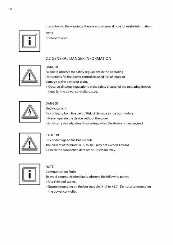
In addition to the warnings, there is also a general note for useful information.
nOtecontent of note
2.2 General danGer InfOrMatIOn
danGerfailure to observe the safety regulations in the operatinginstructions for the power controllers used risk of injury ordamage to the device or plant.> Observe all safety regulations in the safety chapter of the operating instruc-
tions for the power controllers used.
danGerelectric currentrisk of injury from live parts / risk of damage to the bus module> never operate the device without the cover.> Only carry out adjustments or wiring when the device is deenergised.
caUtIOn risk of damage to the bus modulethe current at terminals X1.5 to X8.5 may not exceed 120 ma.> check the connection data of the upstream relay.
nOtecommunication faultsto avoid communication faults, observe the following points:> Use shielded cables.> ensure grounding on the bus module (X1.7 to X8.7). do not also ground on
the power controller.
11
2.3 OPeratOr reqUIreMentSthe operator must ensure the following:· that the safety regulations of the operating instructions are observed.· that the accident prevention regulations valid in the respective country of use and the general safety regulations are observed.
· that all safety devices (covers, warning signs etc.) are present, in perfect condition and are used correctly.
· that national and regional safety regulations are observed.· that the personnel has access to the operating instructions and safety regu-lations at all times.
· that operating conditions and restrictions resulting from the technical data are observed.
· that, should abnormal voltages, noises, increased temperatures, vibration or similar occur, the device is immediately put out of operation and the mainte-nance personnel is informed.
2.4 PerSOnnel reqUIreMentSOnly qualified electro-technical personnel who are familiar with thepertinent safety and installation regulations may perform the following:- transport- Installation- connection- Start-up- Maintenance- testing- Operation.
these operating instructions must be read carefully by all personsworking with or on the equipment prior to installation and initial start-up.
2.5 Intended PUrPOSethe device may only be used for the pupose for which it was intended,as persons may otherwise be exposed to dangers (e.g. electric shock,burns) and plants also (e.g. overload). the user must therefore observethe following points:- It is not permitted to make any unauthorised modifications to the unit or to
use any spare parts or replacement parts not approved by advanced energy, or to use the unit for any other purpose.
- the warranty obligations of the manufacturer are only applicable if these operating instructions are observed and complied with.

12
- the device is a component that cannot function alone.- Project planning must account for the proper use of the device.
2.6 USe Of the deVIce
2.6.1 OPeratIOn- Only switch on the mains voltage at the machine when there is no danger to
persons, system or load.- Protect the device against dust and damp.- ensure that the ventilation openings are not blocked.
2.6.2 PrIOr tO InStallatIOn / Start-UP- If stored in a cold environment: ensure that the device is absolutely dry. (al-
low the device a period of at least two hours to acclimatise before start-up.)- ensure sufficient ventilation of the cubicle if mounted in a cubicle.- Observe minimum spacing.- ensure that the device cannot be heated up by heat sources below it.- Ground the device in accordance with local regulations.- connect the device in accordance with the connection diagram.
2.6.3 MaIntenance, SerVIce, faUltSIn order to avoid injuries and damage, the user must observe thefollowing:- before all work:> disconnect the device from all external voltage sources.> Secure the device against accidentally being switched back on.> Use suitable measuring instruments and check that there is no voltage
present. > Ground and short-circuit the device.> Provide protection by covers or barriers for any neighbouring live parts.- the device may only be serviced and repaired by trained electrotechnical
personnel.
2.6.4 tranSPOrt- Only transport the device in the original packaging.- Protect the device against damage, caused, for instance, by jolts, knocks and
contamination.
13
3. InStallatIOn & SetUP
3.1 InStallatIOnMake sure that the control section is switched off. Plug the devicenet inter-face card into the extension slot and install the cover plate.
3.2 SetUP the addreSSfor communication the devicenet interface card needs an address (0-63). for this the same address is used, which is also used for communi-cation via lWl (fibre optics) and rS232. this can be adjusted with the lba-2, the thyro-tool family and of course via devicenet. for devicenet the address range goes from 0 to 63. all addresses greater than 63 will be interpreted as 63. after change of address a save is produced. that means all actual settings are also saved.
attentIOnthe power controller must be switched off after a modification of the address via lba-2 or thyro-tool family, in order to activate the new address.
3.3 SetUP the cOMMUnIcatIOn SPeedthis device detects the communication speed of the devicenet. So noadjustment has to be made. the communication speed 125, 250 and 500 kbaud are supported.
3.4 cOnnectIOncable selection, cable routing, shielding, bus connector, bus termination and transmission times are all described in the “devicenet specification, volumes I, II“, published by OdVa.for connection to the devicenet we deliver with the card a standardopen-style connector. figure 3.1 shows how to connect the card to thedevicenet.

14
3.5 cOntrOller SetUPa controller needs an edS file (electronic data sheet) for configuring each devicenet node. therefore register the edS-file, which is de-livered with the devicenet interface card, with the configuration tool. after installing the edS file scan the network for any attached nodes. next step is to configure the scanner. therefore all nodes have to be added to the scanner’s scan list.then for every node the IO-Parameters have to be set. after downloading the configuration to the scanner, the thyro-P is ready for communication.
fIG. 3.1 WIrInG cOnnectIOn

15
4. ObJect SPecIfIcatIOnS
4.1 0X01 IdentIty ObJectthis object provides identification of and general information about thedevice.
attr. Id
acceSS rUle
naMe data tyPe
deScrIPtIOn Of attrIbUte
SeMantIcS Of ValUeS defaUlt
1 Get revision UInt revision of this object.
If updates that require an increase in this value are made, then the value of this attribute increases by 1.
1
2 Get Max Instance
UInt Max. instance number of an object currently created in this class level of the device.
the largest instance number of a created object at this class hierarchy level.
1
tab. 4.1 IdentIty ObJect claSS attrIbUteS
attr. Id
acceSS rUle
naMe data tyPe
deScrIPtIOn Of attrIbUte defaUlt
1 Get Vendor Id UInt Identification of vendor by number. 1017
2 Get device type UInt Indication of general type of product. this device is a commu-nications adapter.
12
3 Get Product code
UInt Identification of a particular product of an individual vendor. 1
4 Get revision StrUct of: revision of the item the Identitiy Object represents.
Major revision
USInt 1
Minor revision
USInt 1
5 Get Status WOrd Summary status of device. 1
6 Get Serial number
dInt Serial number of device. 1
7 Get name Product StrIn
ShOrt_ human-readable identification. thyro-PdevicenetInterface
8 Get State USInt Present state of the device
10 Get/Set heartbeat Intervall
USInt the nominal interval between heartbeat messages in seconds 0
tab. 4.2 IdentIty ObJect InStance attrIbUteS

16
4.2 0X02 MeSSaGe rOUter ObJectthe Message router is implemented as an Object that has no externally visible attributes or Services. It only implements a behavior.
4.3 0X03 deVIcenet ObJect
attr. Id
acceSS rUle
naMe data tyPe
deScrIPtIOn Of attrIbUte
SeMantIcS Of ValUeS defaUlt
1 Get revision UInt revision of the devicenet Object class definition upon which the implementation is based.
If updates that require an increase in this value are made, then the value of this attribute increases by 1.
2
tab. 4.4 devicenet ObJect claSS attrIbUteS
attr. Id
acceSS rUle
naMe data tyPe
deScrIPtIOn Of attrIbUte defaUlt
1 Get/Set Mac Id USInt node address. 63
2 Get/Set baud rate USInt baud rate. auto (2)
3 Get/Set bOI bOOl bus-Off interrupt. 1
4 Get/Set bus-Off counter
USInt number of times devicenet went to the bus-Off state. 0
5 Get allocation Information
StrUct of:
allocation choice byte
byte refer to devicenet Specification. 0
Master´s Mac Id
USInt Mac Id of Master (from allocate) 0xff
tab. 4.5 devicenet ObJect InStance attrIbUteS
SerVIce cOde
SUPPOrted SerVIce naMe deScrIPtIOn Of SerVIce
claSS InStance
0x0e yes yes Get_attribute_Single returns the content of the specified attribute.
0x10 n/a yes Set_attribute_Single Modifies a devicenet Object attribute value.
0x05 n/a yes reset Invokes the reset service for the device.
tab. 4.3 IdentIty ObJect SerVIceS

17
SerVIce cOde
SUPPOrted SerVIce naMe deScrIPtIOn Of SerVIce
claSS InStance
0x0e yes yes Get_attribute_Single returns the content of the specified attribute.
0x10 n/a yes Set_attribute_Single Modifies a devicenet Object attribute value.
0x4b n/a yes allocate_Master/ Slave_connection_Set
requests the use of the Predefined Master/Slave connection Set.
0x4c n/a yes release_Group_2_ Identifier_Set
Indicates that the specified connections within the Predefined Master/Slave connection Set are no longer desired. these connections are to be released (deleted).
tab. 4.6 devicenet ObJect SerVIceS
4.4 0X04 aSSeMbly ObJectthe assembly Object binds attributes of multiple objects, which allowsdata to or from each object to be sent or received over a single connection.
attr. Id
acceSS rUle
naMe data tyPe
deScrIPtIOn Of attrIbUte
SeMantIcS Of ValUeS defaUlt
1 Get revision UInt revision of this object.
If updates that require an increase in this value are made, value of this attribute increases by 1.
2
2 Get number of Instances
UInt number of object instances currently created at this class level of the device.
the number of object instances at this class hierarchy level.
6
tab. 4.7 aSSeMbly ObJect claSS attrIbUteS
attr. Id
acceSS rUle
naMe data tyPe
deScrIPtIOn Of attrIbUte defaUlt
3 Get data array the data contained in the assembly object (see assembly).
tab. 4.8 aSSeMbly ObJect InStance attrIbUteS

18
SerVIce cOde
SUPPOrted SerVIce naMe deScrIPtIOn Of SerVIce
claSS InStance
0x0e yes yes Get_attribute_Single returns the content of the specified attribute.
tab. 4.9 aSSeMbly ObJect SerVIceS
4.5 0X05 cOnnectIOn ObJect
cOnnectIOn InStance Id cOnnectIOn
1 explicit connection
2 Polled I/O connection
3-7 dynamic explicit connections
tab. 4.10 cOnnectIOn claSS InStanceS
attr. Id
acceSS rUle
naMe data tyPe
deScrIPtIOn Of attrIbUte
SeMantIcS Of ValUeS defaUlt
1 Get revision UInt revision of this object.
If updates that require an increase in this value are made, then the value of this attribute increases by 1.
1
tab. 4.11 cOnnectIOn claSS attrIbUteS
19
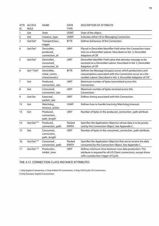
attr. Id
acceSS rUle
naMe data tyPe
deScrIPtIOn Of attrIbUte
1 Get State USInt State of the object.
2 Get Instance_type USInt Indicates either I/0 or Messaging connection
3 Get/Set4 transportclass_ trigger
byte defines behaviour of the connection.
4 Get/Set4 devicenet_ produced_ connection_id
UInt Placed in devicenet Identifier field when the connection trans-mits on a devicenet subnet. described on Vol. 3, devicenet adaption of cIP.
5 Get/Set4 devicenet_ consumed_ connection_id
UInt devicenet Identifier field value that denotes message to be received on a devicenet subnet. described in Vol. 3, devicenet adaption of cIP.
6 Get1/4/Set4 devicenet_ initial_comm_ characteristics
byte defines the Message Group(s) across which productions and consumptions associated with this connection occur on a de-vicenet subnet. described in Vol. 3, devicenet adaption of cIP.
7 Get Produced_ connection_size
UInt Maximum number of bytes transmitted across this connection.
8 Get consumed_ connection_size
UInt Maximum number of bytes received across this connection.
9 Get/Set expected_ packet_rate
UInt defines timing associated with this connection.
12 Get Watchdog_ timeout_action
USInt defines how to handle Inactivity/Watchdog timeouts
13 Get Produced_ connection_ path_length
UInt number of bytes in the produced_connection_path attribute
14 Get/Set2/3/4 Produced_ connection_path
Packed ePath
Specifies the application Object(s) whose data is to be produ-ced by this connection Object. See appendix c.
15 Get consumed_ connection_ path_length
UInt number of bytes in the consumed_connection_path attribute.
16 Get/Set2/3/4 consumed_ connection_path
Packed ePath
Specifies the application Object(s) that are to receive the data consumed by this connection Object. See appendix c.
17 Get/Set2/3/4 Production_ inhibit_time
UInt defines minimum time between new data production. this attribute is required for all I/O client connections, except those with a production trigger of cyclic.
tab. 4.12 cOnnectIOn claSS InStance attrIbUteS
1 Only explicit connection, 2 Only Polled I/O connection, 3 Only cOS/cyclic I/O connection,4 Only dynamic explicit connections
20
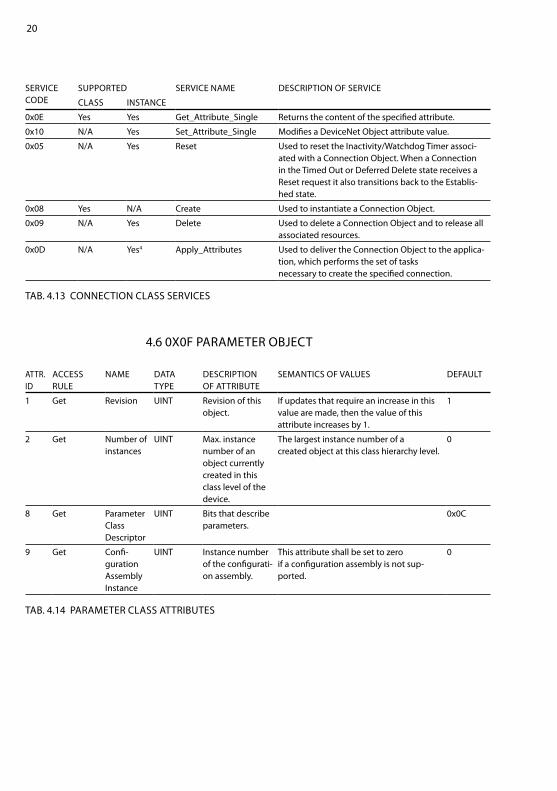
SerVIce cOde
SUPPOrted SerVIce naMe deScrIPtIOn Of SerVIce
claSS InStance
0x0e yes yes Get_attribute_Single returns the content of the specified attribute.
0x10 n/a yes Set_attribute_Single Modifies a devicenet Object attribute value.
0x05 n/a yes reset Used to reset the Inactivity/Watchdog timer associ-ated with a connection Object. When a connection in the timed Out or deferred delete state receives a reset request it also transitions back to the establis-hed state.
0x08 yes n/a create Used to instantiate a connection Object.
0x09 n/a yes delete Used to delete a connection Object and to release all associated resources.
0x0d n/a yes4 apply_attributes Used to deliver the connection Object to the applica-tion, which performs the set of tasks necessary to create the specified connection.
tab. 4.13 cOnnectIOn claSS SerVIceS
4.6 0X0f ParaMeter ObJect
attr. Id
acceSS rUle
naMe data tyPe
deScrIPtIOn Of attrIbUte
SeMantIcS Of ValUeS defaUlt
1 Get revision UInt revision of this object.
If updates that require an increase in this value are made, then the value of this attribute increases by 1.
1
2 Get number of instances
UInt Max. instance number of an object currently created in this class level of the device.
the largest instance number of a created object at this class hierarchy level.
0
8 Get Parameter class descriptor
UInt bits that describe parameters.
0x0c
9 Get confi-guration assembly Instance
UInt Instance number of the configurati-on assembly.
this attribute shall be set to zero if a configuration assembly is not sup-ported.
0
tab. 4.14 ParaMeter claSS attrIbUteS

21
SerVIce cOde
SUPPOrted SerVIce naMe deScrIPtIOn Of SerVIce
claSS InStance
0x0e yes n/a Get_attribute_Single returns the content of the specified attribute.
0x15 yes n/a restore restores all parameter values from non-volatile storage.
0x16 yes n/a Save Saves all parameter values to non-volatile storage.
tab. 4.15 ParaMeter claSS SerVIceS
claSS Id GrOUPS Of attrIbUteS deScrIPtIOn
0x64
Setpoints the setpoints controls the output power of the thyro-P.
actual this values showing the actual state of the thyro-P.
functions Via these output values certain functions in the thyro-P can be executed.
hardware detail description of the thyro-P hardware.
0x65 Operating Mode configuration of the operation modes.
times Specified time depending on operation mode.
controls configuration of the regulation.
limit limit configuration for voltage, current I and power.
control characteristic control of the setpoint characteristics.
0x66 temperature control of the heat sink monitoring.
analog outputs configuration of the analog outputs.
Monitoring Monitoring of mains voltage and load.
led & relays configuration of the leds and relays.
Miscellaneous Some other configurations.
tab. 4.16 thyro-P attrIbUteS
4.7 0X64-0X66 VendOr SPecIfIc ObJectthese three classes are for control of the thyro-P. each class has just one instance. table 4.16 shows an overview of all attributes. for more details refer to chapter 9.
22
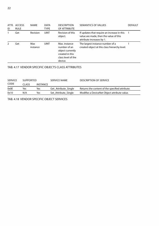
SerVIce cOde
SUPPOrted SerVIce naMe deScrIPtIOn Of SerVIce
claSS InStance
0x0e yes yes Get_attribute_Single returns the content of the specified attribute.
0x10 n/a yes Set_attribute_Single Modifies a devicenet Object attribute value.
tab. 4.18 VendOr SPecIfIc ObJect SerVIceS
attr. Id
acceSS rUle
naMe data tyPe
deScrIPtIOn Of attrIbUte
SeMantIcS Of ValUeS defaUlt
1 Get revision UInt revision of this object.
If updates that require an increase in this value are made, then the value of this attribute increases by 1.
1
2 Get Max instance
UInt Max. instance number of an object currently created in this class level of the device.
the largest instance number of a created object at this class hierarchy level.
1
tab. 4.17 VendOr SPecIfIc ObJectS claSS attrIbUteS
23
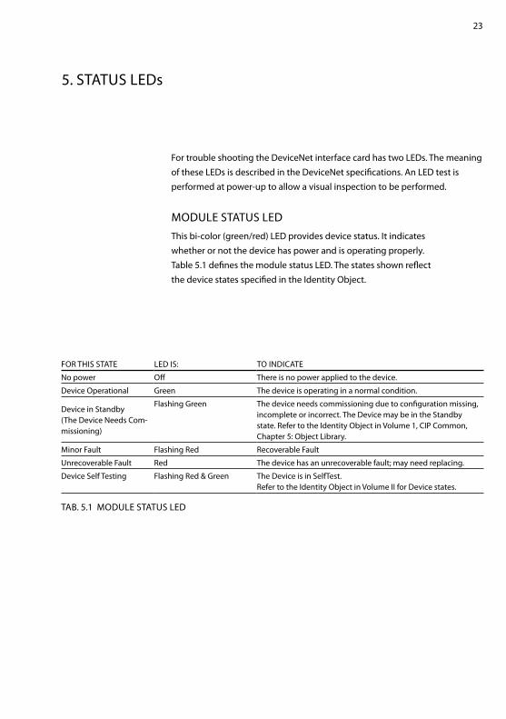
5. StatUS leds
for trouble shooting the devicenet interface card has two leds. the meaning of these leds is described in the devicenet specifications. an led test is performed at power-up to allow a visual inspection to be performed.
MOdUle StatUS ledthis bi-color (green/red) led provides device status. It indicates whether or not the device has power and is operating properly. table 5.1 defines the module status led. the states shown reflect the device states specified in the Identity Object.
fOr thIS State led IS: tO IndIcate
no power Off there is no power applied to the device.
device Operational Green the device is operating in a normal condition.
device in Standby (the device needs com-missioning)
flashing Green the device needs commissioning due to configuration missing, incomplete or incorrect. the device may be in the Standby state. refer to the Identity Object in Volume 1, cIP common, chapter 5: Object library.
Minor fault flashing red recoverable fault
Unrecoverable fault red the device has an unrecoverable fault; may need replacing.
device Self testing flashing red & Green the device is in Selftest. refer to the Identity Object in Volume II for device states.
tab. 5.1 MOdUle StatUS led

24
netWOrk StatUS ledthis bi-color (green/red) led indicates the status of the communicationlink. table 5.2 defines the network status led. the states shown reflect the network access state machine.
fOr thIS State: led IS: tO IndIcate
not Powered not On-line
Off device is not on-line. - the device has not completed the dup_Mac_Id test yet.
- the device may not be powered, look at Module Status led.
On-line, not connected
flashing Green device is on–line but has no connections in the established state.- the device has passed the dup_Mac_Id test, is on–line, but
has no established connections to other nodes.- for a UcMM capable device it means that the device has no
established connections.
link Ok On-line, connected
Green the device is on–line and has connections in the established state.- for a Group 2 Only device it means that the device is allocated
to a Master. - for a UcMM capable device it means that the device has one
or more established connections.
connection time-Out flashing red One or more I/O connections are in the timed–Out state.
critical link failure red failed communication device.
the device has detected an error that has rendered it incapable of communicating on the network (duplicate Mac Id, or bus–off).
communication faulted and received an Identify comm. fault request - long Protocol
flashing red & Green
the device has detected a network access error and is in the communication faulted state. the device has subsequently received and accepted an Identify communication faulted request - long Protocol message.
tab. 5.2 netWOrk StatUS led
25
6. dIGItal InPUtS
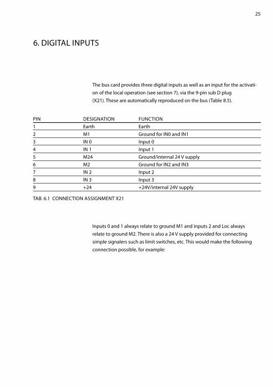
the bus card provides three digital inputs as well as an input for the activati-on of the local operation (see section 7), via the 9-pin sub d plug(X21). these are automatically reproduced on the bus (table 8.5).
Inputs 0 and 1 always relate to ground M1 and inputs 2 and loc alwaysrelate to ground M2. there is also a 24 V supply provided for connecting simple signalers such as limit switches, etc. this would make the following connection possible, for example:
PIn deSIGnatIOn fUnctIOn1 earth earth2 M1 Ground for In0 and In13 In 0 Input 04 In 1 Input 15 M24 Ground/internal 24 V supply6 M2 Ground for In2 and In37 In 2 Input 28 In 3 Input 39 +24 +24V/internal 24V supply
tab. 6.1 cOnnectIOn aSSIGnMent X21

26
fIG. 6.2 eXaMPle Of cOnnectInG InPUtS

27
7. lOcal OPeratIOn Of the SetPOInt MOtOrPOtI
In certain situations, e.g. failure of the bus, is it sometimes necessary tochange the desired value quickly. this can take place over the lba-2. It ishowever pedantic for certain applications too. In order to remove thisdeficiency, the possibility of the local operation of the Setpoint Motorpoti was created via switches.the local operation of the setpoint Motorpoti can be activated via theloc input (pin 8). It is then possible to switch the value SW_actIVbetween remote (open) and local (closed) via the input In0 (pin 3).In the local operation mode the setpoint motorpoti value can be changed over the inputs In1 and In2, whereby the setpoint value with pressed key changes according to figure 7.1. for example the setpoint goes up 30% if the UP key is pressed for 10s. With simultaneous operation of the Up and down keys the desired value is reduced.
fIG. 7.1 relatIVe chanGInG Of the MOtOrPOtI SetPOInt OVer the tIMe
28
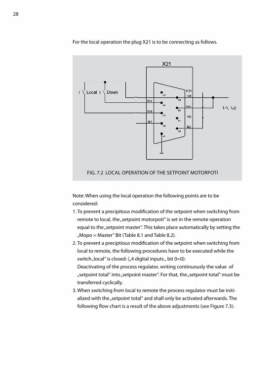
for the local operation the plug X21 is to be connecting as follows.
note: When using the local operation the following points are to beconsidered:1. to prevent a precipitous modification of the setpoint when switching from
remote to local, the „setpoint motorpoti“ is set in the remote operation equal to the „setpoint master“. this takes place automatically by setting the „Mopo = Master“ bit (table 8.1 and table 8.2).
2. to prevent a preciptious modification of the setpoint when switching from local to remote, the following procedures have to be executed while the switch „local“ is closed: („4 digital inputs „ bit 0=0): deactivating of the process regulator, writing continuously the value of „setpoint total“ into „setpoint master“. for that, the „setpoint total“ must be transferred cyclically.
3. When switching from local to remote the process regulator must be initi-alized with the „setpoint total“ and shall only be activated afterwards. the following flow chart is a result of the above adjustments (see figure 7.3).
fIG. 7.2 lOcal OPeratIOn Of the SetPOInt MOtOrPOtI

29
abb. 7.3 State dIaGraM

30
8. aSSeMbly
8.1 aSSeMbly 101: SetPOInt(OUtPUt fOr POll)
byte P.Id tyPe ValUe0 38 byte configuration (table 8.2)1-2 1 UInt Setpoint Master (16383 == 100 [%])3-4 2 UInt Setpoint Master error (16383 == 100 [%])
tab. 8.1 OUtPUt aSSeMbly 101
nOtefor power control the „Setpoint master“ is used in normal operation. If the poll connection is interrupted, or the poll telegram length is zero, then the „Setpoint master error“ is used.
bIt ValUe deScrIPtIOn
0Mopo = Master activate the write of the „Setpoint master“ on the „Setpoint motorpoti“, if
the power controller is in „remote“ operation and the device is on-line and has connections in the established state.
1
all values are local here can be determined, which values can be adjusted in the „local mode“ locally.0 Only the setpoints are locally given.1 no value is given by the master.
2-3
actual values average here the averaging of the actual values can be activated. In the operating mode „takt“ is measured once per t0, with „Var“ once per 0,2s.00 averaging is off01 averaging over 5 Values10 averaging over 10 Values11 averaging over 20 Values
4regulator suppressor through this bit the regulator suppressor can be controlled.
0 regulator suppressor off1 regulator suppressor on
5 Use setpoint new setpoints only taken over if this bit is set.0 Ignore new setpoints1 Use new setpoints
tab. 8.2 deScrIPtIOn Of the cOnfIGUratIOn byte
31
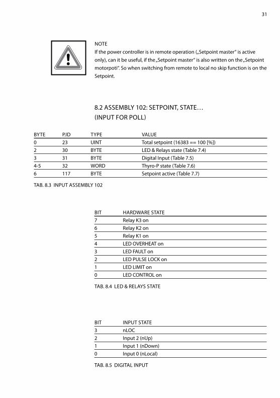
nOteIf the power controller is in remote operation („Setpoint master“ is active only), can it be useful, if the „Setpoint master“ is also written on the „Setpoint motorpoti“. So when switching from remote to local no skip function is on the Setpoint.
8.2 aSSeMbly 102: SetPOInt, State…(InPUt fOr POll)
byte P.Id tyPe ValUe0 23 UInt total setpoint (16383 == 100 [%])2 30 byte led & relays state (table 7.4)3 31 byte digital Input (table 7.5)4-5 32 WOrd thyro-P state (table 7.6)6 117 byte Setpoint active (table 7.7)
tab. 8.3 InPUt aSSeMbly 102
bIt hardWare State7 relay k3 on6 relay k2 on5 relay k1 on4 led OVerheat on3 led faUlt on2 led PUlSe lOck on1 led lIMIt on0 led cOntrOl on
tab. 8.4 led & relayS State
bIt InPUt State3 nlOc2 Input 2 (nUp)1 Input 1 (ndown)0 Input 0 (nlocal)
tab. 8.5 dIGItal InPUt
32
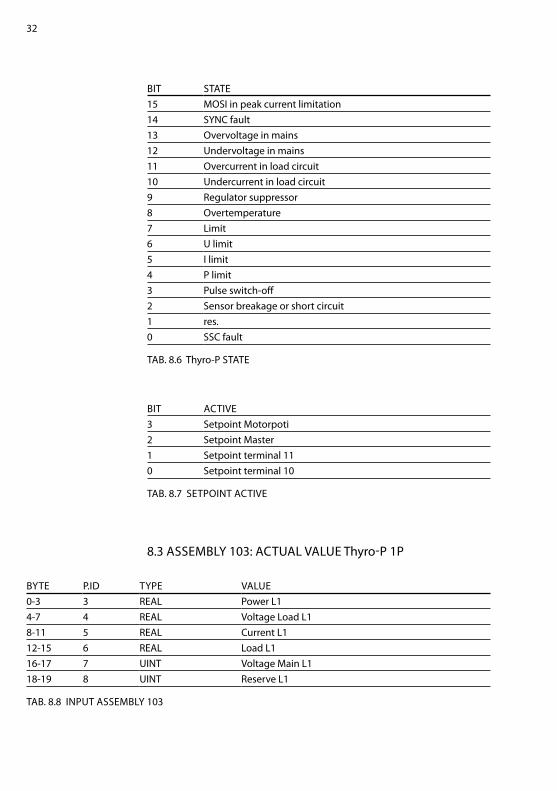
bIt State15 MOSI in peak current limitation14 Sync fault13 Overvoltage in mains12 Undervoltage in mains11 Overcurrent in load circuit10 Undercurrent in load circuit9 regulator suppressor8 Overtemperature7 limit6 U limit5 I limit4 P limit3 Pulse switch-off2 Sensor breakage or short circuit1 res.0 SSc fault
tab. 8.6 thyro-P State
bIt actIVe3 Setpoint Motorpoti2 Setpoint Master1 Setpoint terminal 110 Setpoint terminal 10
tab. 8.7 SetPOInt actIVe
8.3 aSSeMbly 103: actUal ValUe thyro-P 1P
byte P.Id tyPe ValUe0-3 3 real Power l14-7 4 real Voltage load l18-11 5 real current l112-15 6 real load l116-17 7 UInt Voltage Main l118-19 8 UInt reserve l1
tab. 8.8 InPUt aSSeMbly 103

33
8.4 aSSeMbly 104: actUal ValUe thyro-P 2P
byte P.Id tyPe ValUe0-3 3 real Power l14-7 4 real Voltage load l18-11 5 real current l112-15 6 real load l116-17 7 UInt Voltage Main l118-19 8 UInt reserve l120-23 15 real Power l324-27 16 real Voltage load l328-31 17 real current l332-35 18 real load l336-37 19 UInt Voltage Main l338-39 20 UInt reserve l3
tab. 8.9 InPUt aSSeMbly 104
8.5 aSSeMbly 105: actUal ValUe thyro-P 3P
byte P.Id tyPe ValUe0-3 3 real Power l14-7 4 real Voltage load l18-11 5 real current l112-15 6 real load l116-17 7 UInt Voltage Main l118-19 8 UInt reserve l120-23 9 real Power l224-27 10 real Voltage load l228-31 11 real current l232-35 12 real load l236-37 13 UInt Voltage Main l238-39 14 UInt reserve l240-43 15 real Power l344-47 16 real Voltage load l348-51 17 real current l352-55 18 real load l356-57 19 UInt Voltage Main l358-59 20 UInt reserve l3
tab. 8.10 InPUt aSSeMbly 105

34
8.6 aSSeMbly 106: Other actUal ValUe
byte P.Id tyPe ValUe0-3 21 real total power4-5 22 Int temperature6-7 24 UInt Setpoint Motorpoti (16383 == 100 [%])8-9 25 UInt Setpoint terminal 1010-11 26 UInt Setpoint terminal 1112-13 27 UInt On-angle alpha14-15 28 UInt On-time value16-17 29 UInt Period time [ms]
tab. 8.11 InPUt aSSeMbly 106

35
9. attrIbUteS
all attributes are listed in the following tables. the attributes are split into 3 ob-jects (100-102). the Instance is always 1. the epath to a parameter is „20 class.Id 24 01 30 attr.Id“ for example the epath to the „Setpoint Master“ is 20 64 24 01 30 64 (all values hex).
9.1 attrIbUteS Of claSS 0X64
P.Id attr Id SetPOInt tyPe UnIt r/W
1 100 Setpoint Master UInt 16383 == 100[%] r / w
2 101 Setpoint Master error UInt 16383 == 100[%] r / w
tab. 9.1 SetPOIntS
P.Id attr Id SetPOInt tyPe UnIt r / W3 110 Power l1 real [W] r4 111 Voltage load l1 real [V] r5 112 current l1 real [a] r6 113 load l1 real [S] r7 114 Voltage Main l1 UInt [V] r8 115 reserve l1 UInt r
9 120 Power l2 real [W] r10 121 Voltage load l2 real [V] r11 122 current l2 real [a] r12 123 load l2 real [S] r13 124 Voltage Main l2 UInt [V] r14 125 reserve l2 UInt r
15 130 Power l3 real [W] r16 131 Voltage load l3 real [V] r17 132 current l3 real [a] r18 133 load l3 real [S] r19 134 Voltage Main l3 UInt [V] r20 135 reserve l3 UInt r
21 140 total power real [W] r22 141 temperature Int [°c] r

36
23 142 total setpoint UInt 16383 == 100[%] r24 143 Setpoint Motorpoti UInt 16383 == 100[%] r25 144 Setpoint terminal 10 UInt 16383 == 100[%] r26 145 Setpoint terminal 11 UInt 16383 == 100[%] r27 146 On-angle alpha UInt 18000 == 180°el r28 147 On-time value UInt [period] r29 148 Period time UInt [μs] r30 149 led & relays state byte -- r31 150 digital Input byte 4 bit r32 151 thyro-P state WOrd (table 7.6) r33 152 State USInt -- r
tab. 9.2 actUal ValUeS
P.Id attr Id ValUe tyPe ValUe ranGe cOMbO-OPt UnIt r/W defaUlt
34 160 acknowledge bOOl 0...1 Off, qUIt r / w Off
35 161 reset bOOl 0...1 Off, reSet r / w Off
37 163 ext. error message bOOl 0...1 Off, On r / w Off
38 164 configuration byte bit 0 Mopo = Masterbit 1 local valuesbit 2-3 actual values averagebit 4 regular supressorbit 5 Use setpoint
Off, OnSetpoint, allOff, 5, 10, 20 valuesOff, Onno, yes
r / w OffSetpointOff
Offno
39 165 reserve 1 byte r / w 0
40 166 reserve 2 byte r / w 0
tab. 9.3 fUnctIOnS

37
P.Id attr Id ValUe tyPe ValUe ranGe cOMbO-OPt UnIt r/W defaUlt
41 170 Power controller rated current
UInt 0...65535a a r 110
42 171 rated current in lSb UInt 0...65535 r 0
43 172 current converter ratio UInt 0...65535 r 100
44 173 load resistor current UInt 0...653 Ohm 0,01 Ohm r 91
45 174 Scaling factor current UInt 0...65535 r 845
46 175 current value threshold UInt 0...65535 ??? r 65535
47 176 Power controller connection voltage
UInt 0...1000V V r 400
48 177 rated voltage in lSb UInt 0...65535 r 0
49 178 Mains voltage user UInt 0...1000V V r 400
50 179 Voltage converter ratio UInt 0...1000 r 16
51 180 Voltage range changeover
USInt 0...2 230 V, 400 V, 690 V
r 1
52 181 load resistor voltage UInt 0...65535Ohm Ohm r 2000
53 182 load resistor voltage range 1 UInt 0...65535Ohm Ohm r 1111
54 183 load resistor voltage range 2 UInt 0...65535Ohm Ohm r 667
55 184 Scaling factor 230V UInt 0...65535 r 1279
56 185 Scaling factor 400V UInt 0...65535 r 1324
57 186 Scaling factor 500-690V
UInt 0...65535 r 1344
58 187 Min. frequency UInt 14286...25000, 1/X * 10^6
r 22222
59 188 Max. frequency UInt 14286...25000, 1/X * 10^6
r 15151
60 189 frequency tolerance USInt 0...100 % r 10
61 190 Power controller rated power UdInt 0... W r 44000
62 191 rated power hi in lSb UdInt 0... r 0
63 192 Potentiometer regulator parameter ti
UInt 0...65535 r 0
64 193 Potentiometer regulator parameter kp
UInt 0...65535 r 0
65 194 Voltage divider resitor UInt 0...65535 Ohm r 32400
66 195 Meter circuit USInt 0...5 aron 1/2 aron 1, 1/2 aron 2, 1/2 aron 3, asymmetrical load, Symmetrical, load
r 0
tab. 9.4 hardWare
38
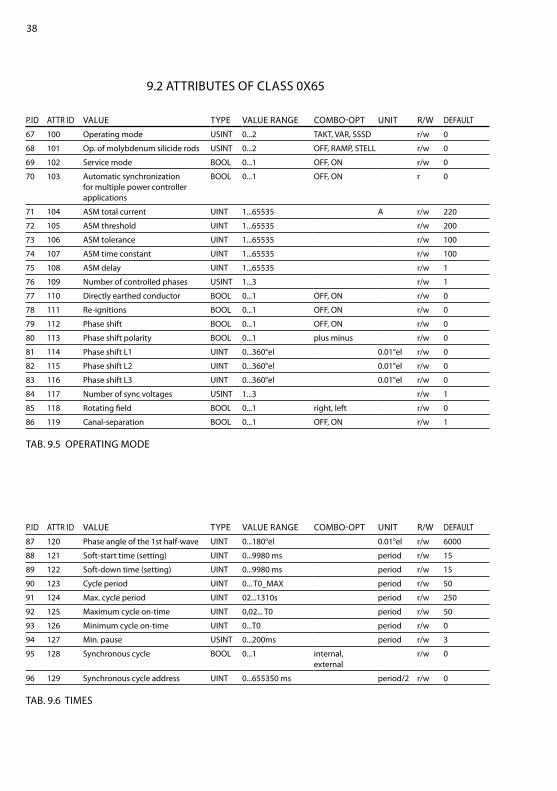
9.2 attrIbUteS Of claSS 0X65
P.Id attr Id ValUe tyPe ValUe ranGe cOMbO-OPt UnIt r/W defaUlt
67 100 Operating mode USInt 0...2 takt, Var, SSSd r/w 0
68 101 Op. of molybdenum silicide rods USInt 0...2 Off, raMP, Stell r/w 0
69 102 Service mode bOOl 0...1 Off, On r/w 0
70 103 automatic synchronization for multiple power controller applications
bOOl 0...1 Off, On r 0
71 104 aSM total current UInt 1...65535 a r/w 220
72 105 aSM threshold UInt 1...65535 r/w 200
73 106 aSM tolerance UInt 1...65535 r/w 100
74 107 aSM time constant UInt 1...65535 r/w 100
75 108 aSM delay UInt 1...65535 r/w 1
76 109 number of controlled phases USInt 1...3 r/w 1
77 110 directly earthed conductor bOOl 0...1 Off, On r/w 0
78 111 re-ignitions bOOl 0...1 Off, On r/w 0
79 112 Phase shift bOOl 0...1 Off, On r/w 0
80 113 Phase shift polarity bOOl 0...1 plus minus r/w 0
81 114 Phase shift l1 UInt 0...360°el 0.01°el r/w 0
82 115 Phase shift l2 UInt 0...360°el 0.01°el r/w 0
83 116 Phase shift l3 UInt 0...360°el 0.01°el r/w 0
84 117 number of sync voltages USInt 1...3 r/w 1
85 118 rotating field bOOl 0...1 right, left r/w 0
86 119 canal-separation bOOl 0...1 Off, On r/w 1
tab. 9.5 OPeratInG MOde
P.Id attr Id ValUe tyPe ValUe ranGe cOMbO-OPt UnIt r/W defaUlt
87 120 Phase angle of the 1st half-wave UInt 0...180°el 0.01°el r/w 6000
88 121 Soft-start time (setting) UInt 0...9980 ms period r/w 15
89 122 Soft-down time (setting) UInt 0...9980 ms period r/w 15
90 123 cycle period UInt 0... t0_MaX period r/w 50
91 124 Max. cycle period UInt 02...1310s period r/w 250
92 125 Maximum cycle on-time UInt 0,02... t0 period r/w 50
93 126 Minimum cycle on-time UInt 0...t0 period r/w 0
94 127 Min. pause USInt 0...200ms period r/w 3
95 128 Synchronous cycle bOOl 0...1 internal, external
r/w 0
96 129 Synchronous cycle address UInt 0...655350 ms period/2 r/w 0
tab. 9.6 tIMeS

39
P.Id attr Id ValUe tyPe ValUe ranGe cOMbO-OPt UnIt r/W defaUlt
97 130 regulation USInt 0...8 Uload^2, Uload eff, Iload^2, Iload eff, real power, res, res, res, without regulation
r/w 0
98 131 Standard regulator bOOl 0...1 Off, On r/w 1
99 132 PId-regulator, I-part UInt 0 = off 0...65535 r/w 800
100 133 PId-regulator, P-part UInt 0 = off 0...65535 r/w 160
101 134 PId-regulator, counter P-part UInt 0...65535 r/w 1
102 135 PId-regulator, d-part UInt 0 = off 0...65535 r/w 0
103 136 PId-regulator, I-part, default value
UInt 0 = off 0...65535 r 800
104 137 PId-regulator, P-part, default value
UInt 0 = off 0...65535 r 160
105 138 PId-regulator, counter P-part, default value
UInt 0...65535 r 1
106 139 PId-regulator, d-part, default value
UInt 0 = off 0...65535 r 0
107 140 rate of angular displacement 1 UInt 0...65535 r/w 1100
108 141 rate of angular displacement 2 UInt 0...65535 r/w 50
tab. 9.7 cOntrOlS
P.Id attr Id ValUe tyPe ValUe ranGe cOMbO-OPt UnIt r/W defaUlt
109 142 Min. r.m.s. voltage setpoint UInt 0...65535 V V r/w 0
110 143 Max. r.m.s. voltage setpoint UInt 0...65535 V V r/w 440
111 144 Min. r.m.s. current setpoint UInt 0...65535 a a r/w 0
112 145 Max. r.m.s. current setpoint UInt 0...65535 a a r/w 110
113 146 Min. power setpoint hi UdInt 0... W r/w 0
114 147 Max. power setpoint hi UdInt 0... W r/w 48400
115 148 front pulse limit position UInt 0...180°el 0.01°el r/w 18000
116 149 back pulse limit position UInt 0...180°el 0.01°el r/w 0
tab. 9.8 lIMIt
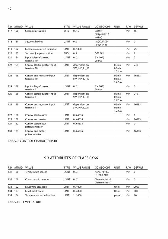
40
P.Id attr Id ValUe tyPe ValUe ranGe cOMbO-OPt UnIt r/W defaUlt
117 150 Setpoint activation byte 0...15 bit 0 = 1 (Setpoint t10 active) ...
r/w 15
118 151 Setpoint linking USInt 0...3 _add, Iadd, _PrO, IPrO
r/w 0
119 152 factor peak current limitation UInt 0...1000 r/w 25
120 153 Setpoint jump correction bOOl 0..1 Off, On r/w 1
121 154 Input voltage/current terminal 10
USInt 0...2 5 V, 10 V, 20 ma
r/w 2
122 155 control start regulator input terminal 10
UInt dependent on SW_InP_IU_10
0.3mV 0.6mV 1.22ua
r/w 240
123 156 control end regulator input terminal 10
UInt dependent on SW_InP_IU_10
0.3mV 0.6mV 1.22ua
r/w 16383
124 157 Input voltage/current terminal 11
USInt 0...2 5 V, 10 V, 20 ma
r/w 0
125 158 control start regulator input terminal 11
UInt dependent on SW_InP_IU_11
0.3mV 0.6mV 1.22ua
r/w 240
126 159 control end regulator input terminal 11
UInt dependent on SW_InP_IU_11
0.3mV 0.6mV 1.22ua
r/w 16383
127 160 control start master UInt 0...65535 r/w 0
128 161 control end master UInt 0...65535 r/w 16383
129 162 control start motor potentiomenter
UInt 0...65535 r/w 0
130 163 control end motor potentiometer
UInt 0...65535 r/w 16383
tab. 9.9 cOntrOl characterIStIc
P.Id attr Id ValUe tyPe ValUe ranGe cOMbO-OPt UnIt r/W defaUlt
131 100 temperature sensor USInt 0...3 none, Pt100, Pt1000, ntc
r/w 0
132 101 characteristic number USInt 0...7 characteristc 0... characteristic 7
r/w 0
133 102 level wire breakage UInt 0...4000 Ohm r/w 2000
134 103 level short circuit UInt 0...4000 Ohm r/w 800
135 104 temperature error duration UInt 1...1000 period r/w 10
tab. 9.10 teMPeratUre
9.3 attrIbUteS Of claSS 0X66
41
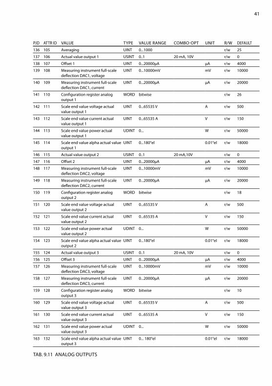
P.Id attr Id ValUe tyPe ValUe ranGe cOMbO-OPt UnIt r/W defaUlt
136 105 averaging UInt 0...1000 r/w 25
137 106 actual value output 1 USInt 0..1 20 ma, 10V r/w 0
138 107 Offset 1 UInt 0...20000µa µa r/w 4000
139 108 Measuring instrument full-scale deflection dac1, voltage
UInt 0...10000mV mV r/w 10000
140 109 Measuring instrument full-scale deflection dac1, current
UInt 0...20000µa µa r/w 20000
141 110 configuration register analog output 1
WOrd bitwise r/w 26
142 111 Scale end value voltage actual value output 1
UInt 0...65535 V a r/w 500
143 112 Scale end value current actual value output 1
UInt 0...65535 a V r/w 150
144 113 Scale end value power actual value output 1
UdInt 0... W r/w 50000
145 114 Scale end value alpha actual value output 1
UInt 0...180°el 0.01°el r/w 18000
146 115 actual value output 2 USInt 0..1 20 ma,10V r/w 0
147 116 Offset 2 UInt 0...20000µa µa r/w 4000
148 117 Measuring instrument full-scale deflection dac2, voltage
UInt 0...10000mV mV r/w 10000
149 118 Measuring instrument full-scale deflection dac2, current
UInt 0...20000µa µa r/w 20000
150 119 configuration register analog output 2
WOrd bitwise r/w 18
151 120 Scale end value voltage actual value output 2
UInt 0...65535 V a r/w 500
152 121 Scale end value current actual value output 2
UInt 0...65535 a V r/w 150
153 122 Scale end value power actual value output 2
UdInt 0... W r/w 50000
154 123 Scale end value alpha actual value output 2
UInt 0...180°el 0.01°el r/w 18000
155 124 actual value output 3 USInt 0..1 20 ma, 10V r/w 0
156 125 Offset 3 UInt 0...20000µa µa r/w 4000
157 126 Measuring instrument full-scale deflection dac3, voltage
UInt 0...10000mV mV r/w 10000
158 127 Measuring instrument full-scale deflection dac3, current
UInt 0...20000µa µa r/w 20000
159 128 configuration register analog output 3
WOrd bitwise r/w 10
160 129 Scale end value voltage actual value output 3
UInt 0...65535 V a r/w 500
161 130 Scale end value current actual value output 3
UInt 0...65535 a V r/w 150
162 131 Scale end value power actual value output 3
UdInt 0... W r/w 50000
163 132 Scale end value alpha actual value output 3
UInt 0... 180°el 0.01°el r/w 18000
tab. 9.11 analOG OUtPUtS

42
P.Id attr Id ValUe tyPe ValUe ranGe cOMbO-OPt UnIt r/W defaUlt
164 133 Mains voltage monitoring minimum
UInt 0...1000 V V r/w 320
165 134 Mains voltage monitoring maximum
UInt 0...1000 V V r/w 480
166 135 Undercurrent monitoring bOOl 0...1 Off, On r/w 0
167 136 Overcurrent monitoring bOOl 0...1 Off, On r/w 0
168 137 load break bOOl 0...1 rel_, abS r/w 0
169 138 Undercurrent monitoring value UInt 0...99 % % r/w 0
170 139 Overcurrent monitoring value UInt 0...255 % % r/w 0
171 140 Undercurrent monitoring value UInt 0...65535 r/w 0
172 141 Overcurrent monitoring value UInt 0...65535 r/w 0
173 142 Monitoring l2 enable bOOl 0...1 Off, On r/w 0
174 143 Monitoring l3 enable bOOl 0...1 Off, On r/w 0
tab. 9.12 MOnItOrInG

43
P.Id attr Id ValUe tyPe ValUe ranGe cOMbO-OPt UnIt r/W defaUlt
175 144 led & relays work princ,iple byte 0...256, bitewise Open-circuit principle, closed-circuit, principle
r/w 224
176 145 led cOntrOl mode WOrd 0...65535 r/w 4096
177 146 led lIMIt mode WOrd 0...65535 r/w 0
178 147 led PUlSe lOck mode WOrd 0...65535 r/w 0
179 148 led faUlt mode WOrd 0...65535 r/w 1792
180 149 led OVerheat mode WOrd 0...65535 r/w 0
181 150 relay k1 mode WOrd 0...65535 r/w 1792
182 151 relay k2 mode WOrd 0...65535 r/w 768
183 152 relay k3 mode WOrd 0...65535 r/w 59392
184 153 led cOntrOl config 0 WOrd 0...65535 r/w 0
185 154 led lIMIt config 0 WOrd 0...65535 r/w 2048
186 155 led PUlSe lOck config 0 WOrd 0...65535 r/w 256
187 156 led faUlt config 0 WOrd 0...65535 r/w 0
188 157 led OVerheat config 0 WOrd 0...65535 r/w 0
189 158 relay k1 config 0 WOrd 0...65535 r/w 0
190 159 relay k2 config 0 WOrd 0...65535 r/w 2048
191 160 relay k3 config 0 WOrd 0...65535 r/w 1
192 161 led control config 1 WOrd 0...65535 r/w 0
193 162 led lIMIt config 1 WOrd 0...65535 r/w 0
194 163 led PUlSe lOck config 1 WOrd 0...65535 r/w 0
195 164 led faUlt config 1 WOrd 0...65535 r/w 256
196 165 led OVerheat config 1 WOrd 0...65535 r/w 0
197 166 relay k1 config 1 WOrd 0...65535 r/w 256
198 167 relay k2 config 1 WOrd 0...65535 r/w 0
199 168 relay k3 config 1 WOrd 0...65535 r/w 0
tab. 9.13 led & relayS
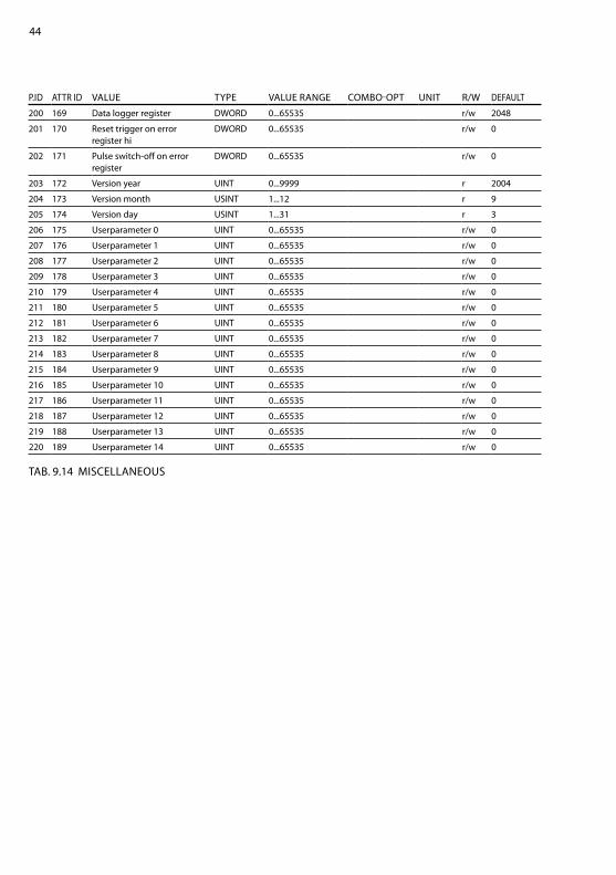
44
P.Id attr Id ValUe tyPe ValUe ranGe cOMbO-OPt UnIt r/W defaUlt
200 169 data logger register dWOrd 0...65535 r/w 2048
201 170 reset trigger on error register hi
dWOrd 0...65535 r/w 0
202 171 Pulse switch-off on error register
dWOrd 0...65535 r/w 0
203 172 Version year UInt 0...9999 r 2004
204 173 Version month USInt 1...12 r 9
205 174 Version day USInt 1...31 r 3
206 175 Userparameter 0 UInt 0...65535 r/w 0
207 176 Userparameter 1 UInt 0...65535 r/w 0
208 177 Userparameter 2 UInt 0...65535 r/w 0
209 178 Userparameter 3 UInt 0...65535 r/w 0
210 179 Userparameter 4 UInt 0...65535 r/w 0
211 180 Userparameter 5 UInt 0...65535 r/w 0
212 181 Userparameter 6 UInt 0...65535 r/w 0
213 182 Userparameter 7 UInt 0...65535 r/w 0
214 183 Userparameter 8 UInt 0...65535 r/w 0
215 184 Userparameter 9 UInt 0...65535 r/w 0
216 185 Userparameter 10 UInt 0...65535 r/w 0
217 186 Userparameter 11 UInt 0...65535 r/w 0
218 187 Userparameter 12 UInt 0...65535 r/w 0
219 188 Userparameter 13 UInt 0...65535 r/w 0
220 189 Userparameter 14 UInt 0...65535 r/w 0
tab. 9.14 MIScellaneOUS

45
10. technIcal SPecIfIcatIOnS
deVIcenetaddress range 0 - 63 ( 64 - 999 => 63 )communication speed 125, 250 and 500 kbaudconnector Open-style connector
deVIcenet SUPPlyVoltage range 11 - 25 VInrush current (25V) 4 a for 10msOperation current 80 ma max.
featUreSauto baud detectionModule Status lednetwork Status ledcomplete control of all thyro-P attributes

46
World headquarters
1625 Sharp Point drive
fort collins, cO 80525 USa
970.221.4670 Main
970.221.5583 fax
www.advanced-energy.com
Specifications are subject to change without notice.
© 2014 advanced energy Industries, Inc. all rights reserved. advanced energy® and thyro-P™ are trademarks of advanced energy Industries, Inc.

47