Embed Size (px)
Citation preview

CiA Draft Standard 405
CANopen
Interface and Device Profile for
IEC 61131-3 Programmable Devices
Version 2.0 Date: 21.05.2002
© CAN in Automation e. V.


CiA DS 405 Interface and Device Profile for IEC 61131-3 Programmable Devices CiA e.V.
© CiA 2008 - All rights reserved i
HISTORY
Date Changes
March 1998 Document Version 1.0 released
December 2000 Document Version 2.0 released • editorial changes • adaptation to Version 4.01 of CiA DS-301 • adaptation to Version 3.0 of CiA DSP-302 • function blocks for SDO with arbitrary length • Tool Integration redefined • clarifications
May 2002 Document as Draft Standard Version 2.0 released
General information on licensing and patents
CAN in AUTOMATION (CiA) calls attention to the possibility that some of the elements of this CiA specification may be subject of patent rights. CiA shall not be responsible for identifying any or all such patent rights. Because this specification is licensed free of charge, there is no warranty for this specifica-tion, to the extent permitted by applicable law. Except when otherwise stated in writing the copyright holder and/or other parties provide this specification “as is” without warranty of any kind, either expressed or implied, including, but not limited to, the implied warranties of merchantability and fitness for a particular purpose. The entire risk as to the correctness and completeness of the specification is with you. Should this specification prove failures, you assume the cost of all necessary servicing, repair or correction.
© CiA 2008
All rights reserved. Unless otherwise specified, no part of this publication may be reproduced or utilized in any form or by any means, electronic or mechanical, including photocopying and micro-film, without permission in writing from CiA at the address below. CAN in Automation e. V. Kontumazgarten 3 DE - 90429 Nuremberg, Germany Tel.: +49-911-928819-0 Fax: +49-911-928819-79 Url: www.can-cia.org Email: [email protected]

CiA DS 405 Interface and Device Profile for IEC 61131-3 Programmable Devices CiA e.V.
ii © CiA 2008 - All rights reserved
TABLE OF CONTENTS
1 SCOPE 1
2 REFERENCES 2
3 TERMS AND DEFINITIONS 2
3.1 DATA TYPES 2 3.2 VARIABLES 3 3.3 PROGRAM ORGANIZATION UNITS (POU) 3 3.4 CONFIGURATION ELEMENTS 4 3.5 ACCESS TO NETWORK VARIABLES DEFINITION 4 3.6 CANOPEN PROFILE-SPECIFIC DEFINITIONS 4
4 DATA TYPES 5
4.1 DATA TYPE CONVERSION FUNCTIONS 6 4.2 DATA TYPE REPRESENTATION ISSUES 7
5 ACCESSING CANOPEN FROM WITHIN IEC 61131-3 8
5.1 VARIABLE BASED ACCESS 8 5.1.1 Definition of the data direction 8 5.1.2 Object dictionary entries for IEC 61131-3 variables 9 5.1.3 Variable names 10
5.2 FUNCTION BLOCK BASED ACCESS 11 5.2.1 General function block design issues 12 5.2.2 Data types 12 5.2.3 SDO access 14 5.2.4 Other function blocks 17
6 TOOL INTEGRATION 20
6.1 BASIC CONCEPT 20 6.2 NODE LIST 20 6.3 ACCESS HANDLER 21
7 UTILITY FUNCTIONS 22
7.1 REMOTE FUNCTIONS BETWEEN RESOURCES 22 7.1.1 Down-/Upload 22
7.2 OBJECT DICTIONARY ENTRIES 22 7.2.1 Project name 22 7.2.2 Configuration 23 7.2.3 Resources 24 7.2.4 Task 25 7.2.5 Start/Stop (Program/Task) 27 7.2.6 Debugging/Monitoring 27
8 APPENDIX (INFORMATIVE) 28
8.1 DETAILED DESCRIPTION OF NETWORK VARIABLE SEGMENTS 28 8.2 IEC 61131-3 OBJECT DICTIONARY OVERVIEW 29 8.3 EXAMPLE DCF FILE 31 8.4 APPLICATION NOTES 31
8.4.1 Network variables 31 8.4.2 Data type representation issues 32 8.4.3 EDS 33 8.4.4 Tool integration 33
8.5 IEC 61131-3 SAMPLE CODE 35 8.6 IMPLEMENTATION MODELS FOR IEC 61131-3 DATA TYPE SUPPORT 35
8.6.1 Native support 35 8.6.2 Padding to next best match 35 8.6.3 Using arrays or struct 36

CiA DS 405 Interface and Device Profile for IEC 61131-3 Programmable Devices CiA e.V.
© CiA 2008 - All rights reserved iii
FIGURES Figure 1: Interfaces ................................................................................................................................1 Figure 2: IEC 61131-3 software organisation.......................................................................................3 Figure 3: Direction of Network Variables ..............................................................................................8 Figure 4: Type CIA405_DEVICE.........................................................................................................12 Figure 5: Type CIA405_SDO_ERROR...............................................................................................12 Figure 6: Type CIA405_EMCY_ERROR ............................................................................................12 Figure 7: Type CIA405_STATE ..........................................................................................................13 Figure 8: Type CIA405_TRANSITION_STATE .................................................................................13 Figure 9: Type CIA405_CANOPEN_KERNEL_ERROR...................................................................13 Figure 10: Function block CIA405_SDO_WRITE4 ............................................................................14 Figure 11: CIA405_SDO_WRITE4 typical timing diagram................................................................14 Figure 12: Function block CIA405_SDO_WRITE ..............................................................................15 Figure 13: Function block CIA405_SDO_READ4..............................................................................16 Figure 14: CIA405_SDO_READ4 typical timing diagram .................................................................16 Figure 15: Function block CIA405_SDO_READ................................................................................17 Figure 16: Function block CIA405_ GET_LOCAL_NODE_ID ..........................................................17 Figure 17: Function block CIA405_ GET_STATE .............................................................................18 Figure 18: Function block CIA405_ GET_CANOPEN_KERNEL_STATE .......................................18 Figure 19: Function block CIA405_ NMT ...........................................................................................18 Figure 20: Function block CIA405_RECV_EMCY_DEV ...................................................................19 Figure 21: Function block CIA405_RECV_EMCY.............................................................................19 Figure 22: Correlation between programming and network configuration .......................................20 Figure 23: Project structure .................................................................................................................22 Figure 24: Data representation with PDO on CANopen non-compliant PLCs.................................32 Figure 25: Data representation with SDO on CANopen non-compliant and compliant PLCs ........32 Figure 26: Information exchange via DCF..........................................................................................33 Figure 27: Data exchange using converter module ...........................................................................33 Figure 28: Compatibility for NVX format .............................................................................................34
TABLES Table 1: Data types ................................................................................................................................5 Table 2: Data types not transferable via PDO......................................................................................6 Table 3: Data type conversion functions ..............................................................................................6 Table 4: Input network variables ...........................................................................................................9 Table 5: Output network variables ......................................................................................................10 Table 6: New data types ......................................................................................................................11 Table 7: Function blocks......................................................................................................................11 Table 8: Error codes for type CIA405_CANOPEN_KERNEL_ERROR ...........................................14 Table 9: Entries in Nodelist file............................................................................................................21 Table 10: List of object dictionary entries ...........................................................................................30


CiA DS 405 Interface and Device Profile for IEC 61131-3 Programmable Devices CiA e.V.
© CiA 2008 - All rights reserved 1
1 Scope This document represents the standardised CANopen Interface and Device Profile for IEC 61131-3 programmable devices like PLCs.
All the above devices use communication techniques which conform to those described in the CiA Draft Standard DS-301 (Application Layer and Communication Profile) and Draft Standard Pro-posal DSP-302. These documents should be consulted in parallel to this profile.
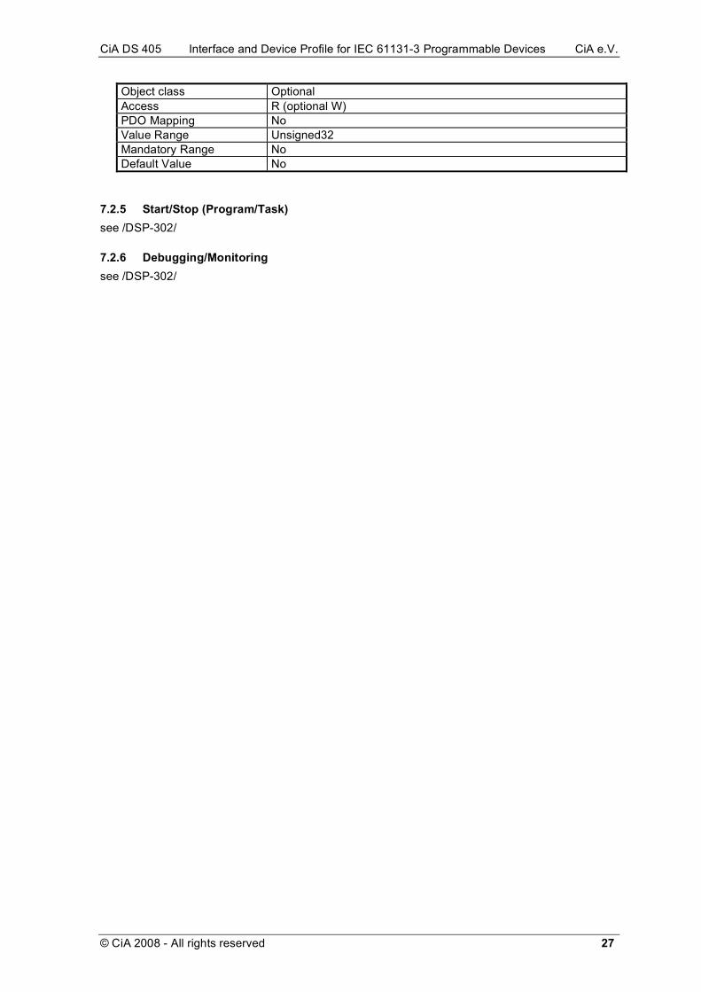
In general, generating an application implements the handling of up to five interfaces see the fig-ure.
Figure 1: Interfaces
This paper covers the following interfaces
A) the access to a CANopen communication system from within an IEC 61131-3 program a) based on variables, i.e. access to elementary IEC 61131-3 variable objects, b) based on calls to function block
B) utility functions for debugging, monitoring and network management C) interface between CANopen tools and IEC 61131-3 programming environment All other interfaces are manufacturer specific (D) or uses CANopen services (E).
Note Figure 1 describes not necessarily the use of different tool for programming and configuration. One tool may handle both functionality and hide the interfaces.
IEC 61131-3 PLC
IEC 61131-3 Programming environment
CANopen tools (e.g. Network configuration
tools)
CANopen Network
Application (IEC 61131-3 Program)
C
D
E B
A
CiA DS 405 Interface and Device Profile for IEC 61131-3 Programmable Devices CiA e.V.
2 © CiA 2008 - All rights reserved
2 References /IEC 61131/ IEC 61131 First edition 1993-03
Programmable controllers - Part 1: general information - Part 3: programming languages - Part 5: messaging services
/DS-301/ Application Layer and Communication Profile CiA Draft Standard 301 Version 4.01, 2000-06
/DSP-302/ Framework for programmable CANopen devices CiA Draft Standard Proposal 302 Version 3.0, 2000-06
/DSP-305/ Layer Setting Services and Protocols CiA Draft Standard Proposal 305 Version 1.1, 2002-02
/DSP-306/ Electronic Data Sheet Specification for CANopen CiA Draft Standard Proposal 306 Version 1.1, 2001-06
3 Terms and definitions
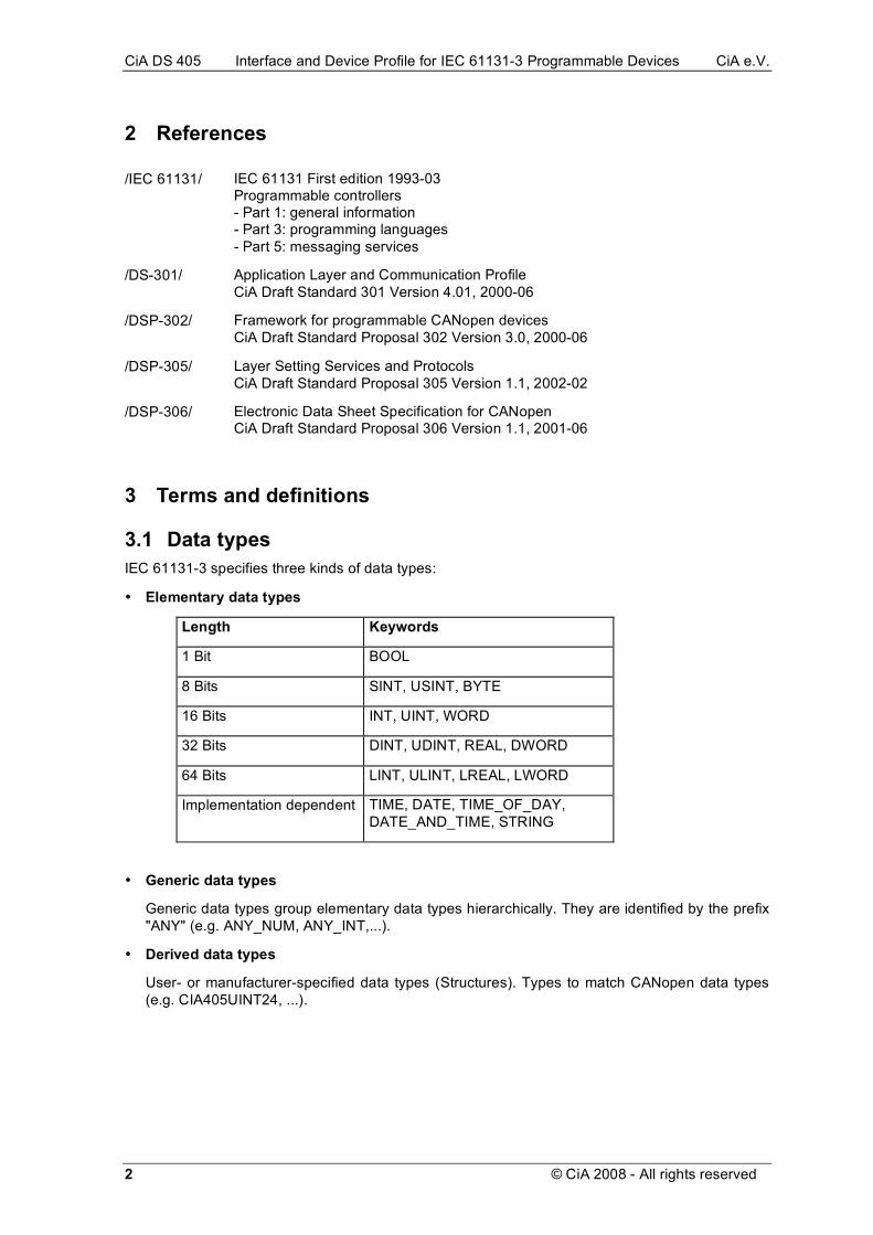
3.1 Data types IEC 61131-3 specifies three kinds of data types:
• Elementary data types
Length Keywords
1 Bit BOOL
8 Bits SINT, USINT, BYTE
16 Bits INT, UINT, WORD
32 Bits DINT, UDINT, REAL, DWORD
64 Bits LINT, ULINT, LREAL, LWORD
Implementation dependent TIME, DATE, TIME_OF_DAY, DATE_AND_TIME, STRING
• Generic data types
Generic data types group elementary data types hierarchically. They are identified by the prefix "ANY" (e.g. ANY_NUM, ANY_INT,...).
• Derived data types
User- or manufacturer-specified data types (Structures). Types to match CANopen data types (e.g. CIA405UINT24, ...).
CiA DS 405 Interface and Device Profile for IEC 61131-3 Programmable Devices CiA e.V.
© CiA 2008 - All rights reserved 3
3.2 Variables IEC-Variables can be represented symbolically or directly (%IX..., %QW ..). IEC 61131-3 knows two kinds of variables:
• Single-element variable
Variable consists of one element.
• Multi-element variable
Arrays and structures.
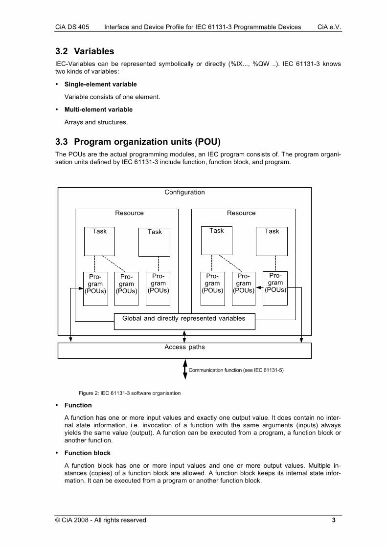
3.3 Program organization units (POU) The POUs are the actual programming modules, an IEC program consists of. The program organi-sation units defined by IEC 61131-3 include function, function block, and program.
Configuration
Resource Resource
Task Task
Pro-gram
(POUs)
Pro-gram
(POUs)
Pro-gram
(POUs)
Global and directly represented variables
Access paths
Task Task
Pro-gram
(POUs)
Pro-gram
(POUs)
Pro-gram
(POUs)
Communication function (see IEC 61131-5)
Figure 2: IEC 61131-3 software organisation
• Function
A function has one or more input values and exactly one output value. lt does contain no inter-nal state information, i.e. invocation of a function with the same arguments (inputs) always yields the same value (output). A function can be executed from a program, a function block or another function.
• Function block
A function block has one or more input values and one or more output values. Multiple in-stances (copies) of a function block are allowed. A function block keeps its internal state infor-mation. It can be executed from a program or another function block.

CiA DS 405 Interface and Device Profile for IEC 61131-3 Programmable Devices CiA e.V.
4 © CiA 2008 - All rights reserved
• Program
This POU type represents the "main program". Instances of programs can only be created within resources (by a task).
3.4 Configuration elements The configuration corresponds to a programmable controller system as defined in IEC 61131-3-1. A configuration contains one or more resources, each of which contains one or more programs executed under the control of zero or more tasks.
• Global variable
A variable whose scope is global (Scope of a declaration applying to all POUs within a resource or configuration).
• Resource
"Signal processing function" and its "man-machine interface" and "sensor and actuator interface functions ", as defined in IEC 61131-3-1. Normally a resource means one PLC’s central proc-essing unit.
• Task
A task is defined as an execution control element which is capable of invoking, either on a peri-odic basis or upon the occurence of the rising edge of a specific Boolean variable, the execution of a set of program organization units, which can include programs and function blocks.
• Access path
The association of a symbolic name with a variable for the purpose of open communication.
3.5 Access to network variables definition In a network programmable nodes can be characterized as a process having input variables and output variables. The set of variables will be arguments of the program and hence will be only known in a final state when the program has been written. The arguments must be handled as variables located in the object dictionary.
This profile uses the terms and definitions of /DSP-302/ "Framework for programmable CANopen Devices". It defines the usage of network variables in a way independent of the type of the pro-grammable device. Here, some restrictions are made for IEC 61131-3 programmable devices.
3.6 CANopen profile-specific definitions CANopen provides the ability to identify the profile of a node. Therefore the CANopen Communica-tion Profile /DS-301/ specifies an object 1000h ("Device Type"). The object 1000h is a 32 Bit word, subdivided into two 16 Bit words. The LSB contains the profile number, the MSB contains addi-tional information. For a device, following these specification the profile number is set to 405. The additional information (MSB) is set to 0 and is reserved for further use by CiA. The profile does not define a default mapping.

CiA DS 405 Interface and Device Profile for IEC 61131-3 Programmable Devices CiA e.V.
© CiA 2008 - All rights reserved 5
4 Data types IEC 61131-3 and CANopen define different data types. The following table defines the assignment of types that are equivalent and that are usable as network variables. For a handling of these data types in a file format it is useful to assign numbers to the data type. The table starts with the data types that are defined in CANopen and uses the same coding. Additional data types of IEC 61131-3 start with A0H.
IEC 61131-3 CANopen Data width (bit) Encoding (Hex)
BOOL Boolean 1 01
SINT Integer8 8 02
INT Integer16 16 03
CIA405INT24 Integer24 24 10
DINT Integer32 32 04
CIA405INT40 Integer40 40 12
CIA405INT48 Integer48 48 13
CIA405INT56 Integer56 56 14
LINT Integer64 64 15
USINT Unsigned8 8 05
UINT Unsigned16 16 06
CIA405UINT24 Unsigned24 24 16
UDINT Unsigned32 32 07
CIA405UINT40 Unsigned40 40 18
CIA405UINT48 Unsigned48 48 19
CIA405UINT56 Unsigned56 56 1A
ULINT Unsigned64 64 1B
REAL Float 32 08
BYTE Unsigned8 8 A4
WORD Unsigned16 16 A5
DWORD Unsigned32 32 A6
LWORD Unsigned64 64 A7
Table 1: Data types

CiA DS 405 Interface and Device Profile for IEC 61131-3 Programmable Devices CiA e.V.
6 © CiA 2008 - All rights reserved
The following data types are equivalent, but cannot be transferred via PDOs:
IEC 61131-3 CANopen Encoding (Hex)
TIME Time_Difference 0D
DATE Time_Of_Day 0C
TIME_OF_DAY Time_Of_Day 0C
STRING Visible String 09
Table 2: Data types not transferable via PDO
The following IEC 61131-3 data types do have no equivalent in CANopen: LREAL, DATE_AND_TIME,. The following CANopen data types do have no equivalent in IEC 61131-3: Octet String, Domain.
4.1 Data type conversion functions Type conversion functions shall be defined as in IEC 61131-3 (i.e. <from>_TO_<to>, e.g. CIA405uint24_TO_DINT) in both directions for the following combinations:
Type1 Type2
CIA405INT24 DINT
CIA405INT40 LINT
CIA405INT48 LINT
CIA405INT56 LINT
CIA405UINT24 UDINT
CIA405UINT40 ULINT
CIA405UINT48 ULINT
CIA405UINT56 ULINT
CIA405UINT24 DWORD
CIA405UINT40 LWORD
CIA405UINT48 LWORD
CIA405UINT56 LWORD
Table 3: Data type conversion functions

CiA DS 405 Interface and Device Profile for IEC 61131-3 Programmable Devices CiA e.V.
© CiA 2008 - All rights reserved 7
4.2 Data type representation issues CANopen defines a certain representation for data types, while IEC 61131-3 does not. If the IEC 61131-3 system can use the same representation as defined in CANopen, there will be no prob-lem. The strategy of this standard is as follows:
a) Data of the network (typically PDOs) made available to the IEC 61131-3 as network variables through entries in the range A000-AFFF, typically mapped into the process image of the IEC 61131-3 system shall be presented to the IEC 61131-3 in the IEC 61131-3 system's native (plat-form dependent, potentially CANopen non-compliant) data representation. The CANopen data type of these data items is known to the CANopen kernel, all necessary conversions will have to be done before putting the value into the process image resp. after retrieving it from the process image.
b) All other data, for which the data type is potentially unknown to the CANopen kernel and/or the IEC 61131-3 application (e.g. SDO data) shall be presented to the IEC 61131-3 system in stan-dard CANopen data format as a stream of raw bytes. Conversion functions shall be supplied to convert this data representation to native IEC 61131-3 format, but the knowledge about the data type has to be available at run-time.
Refer Chapter 8.4.2 for application notes.

CiA DS 405 Interface and Device Profile for IEC 61131-3 Programmable Devices CiA e.V.
8 © CiA 2008 - All rights reserved
5 Accessing CANopen from within IEC 61131-3 As mentioned in the introduction, this paper covers two methods of accessing the CANopen net-work:
1. Variable-based access, accessing individual variables from within the IEC 61131-3 program according to the Network Variables of /DSP-302/.
2. Function block based access, calling function blocks to write and/or read data. This is imple-mented with SDO access.
3. Additional management functions for processing Emergency, LSS and Network state informa-tion.
5.1 Variable based access All objects located in the range A000h - AFFFh of the object dictionary of a node shall be visible as variables to an application on that node programmed within IEC 61131-3. Which kind of variables are being used, e.g.
• directly represented variables
• external variables
• parameters (of programs or function blocks)
shall be left to the IEC 61131-3 implementation.
5.1.1 Definition of the data direction The terms input and output are defined in the Framework for Programmable Devices /DSP-302/. An input has the CANopen data direction ro, an output has the CANopen data direction wo (rww respectively) as with every other device type, too.
Hint:
This definition comes from the network point of view. This shall be explained in Figure 3 by an ex-ample for transferring a physical input:
CAN
IO Devicephysical input 6000H,1
TxPDO
RxPDO
DPRAM
write to
DPRAM
write to
application
PLCA4C0H
Figure 3: Direction of Network Variables
The object A4C0H is defined as an output, since another device can write values to it, which is (from the CANopen point of view) the same as writing a value to a digital output. If the device has a

CiA DS 405 Interface and Device Profile for IEC 61131-3 Programmable Devices CiA e.V.
© CiA 2008 - All rights reserved 9
physical output or a software, that deals with these values - is in principle no difference. So one can use the terminology of “writing values to the PLC application”.
From the PLC programmers point of view, the application will read the value – this is the same as if it would read the digital input lines directly without having a bus between.
5.1.2 Object dictionary entries for IEC 61131-3 variables The Framework for Programmable Devices /DSP-302/ defines the usage of so-called segments. It leaves the concrete placement of the segments open. To ease implementations and for a much easier usage of software from different manufacturers, the usage of the segments is specified for IEC 61131-3 programmed devices: The segments are placed in the index range A000h -AFFFh. This allows any device of another profile (e.g. I/O device or drive unit) to use the standard object dictionary entries of that profile and additionally use the Network Variables.
Inputs:
Start-Index Data Type Direction
A000H Integer8 ro
A040H Unsigned8 ro
A080H Boolean ro
A0C0H Integer16 ro
A100H Unsigned16 ro
A140H Integer24 ro
A180H Unsigned24 ro
A1C0H Integer32 ro
A200H Unsigned32 ro
A240H Float (32) ro
A280H Unsigned40 ro
A2C0H Integer40 ro
A300H Unsigned48 ro
A340H Integer48 ro
A380H Unsigned56 ro
A3C0H Integer56 ro
A400H Integer64 ro
A440H Unsigned64 ro
Table 4: Input network variables

CiA DS 405 Interface and Device Profile for IEC 61131-3 Programmable Devices CiA e.V.
10 © CiA 2008 - All rights reserved
Outputs: Start-Index Data Type Direction
A480H Integer8 rww
A4C0H Unsigned8 rww
A500H Boolean rww
A540H Integer16 rww
A580H Unsigned16 rww
A5C0H Integer24 rww
A600H Unsigned24 rww
A640H Integer32 rww
A680H Unsigned32 rww
A6C0H Float (32) rww
A700H Unsigned40 rww
A740H Integer40 rww
A780H Unsigned48 rww
A7C0H Integer48 rww
A800H Unsigned56 rww
A840H Integer56 rww
A880H Integer64 rww
A8C0H Unsigned64 rww
Table 5: Output network variables
This distribution described according to the /DSP-302/ description rules is given in the Appendix.
The entries MaxCnt, missing in the list above, depend on the available memory of the device. For a further simplification, the EDS files for devices following DS-405 are allowed to omit this descrip-tion. This is marked by setting additionally the second bit of the entry DynamicChannelsSupported of section DeviceInfo:
[DeviceInfo] .... DynamicChannelsSupported=3
5.1.3 Variable names Object dictionary entries which have names that are no legal variable names for IEC 61131-3 shall not be usable to the IEC 61131-3 system. No automatic renaming is defined by this paper.

CiA DS 405 Interface and Device Profile for IEC 61131-3 Programmable Devices CiA e.V.
© CiA 2008 - All rights reserved 11
5.2 Function block based access IEC 61131-3 Function blocks
This chapter describes standard function blocks to access CANopen from IEC 61131-3. All function blocks and data types defined in this chapter are optional in the sense of CANopen standardisa-tion.
The following table can be used by IEC 61131-3 compliant systems to state the features covered:
Nr. Data type
1 CIA405_DEVICE
2 CIA405_SDO_ERROR
3 CIA405_EMCY_ERROR
4 CIA405_STATE
5 CIA405_TRANSITION_STATE
6 CIA405_CANOPEN_KERNEL_ERROR
Table 6: New data types
Nr. Function block
1 CIA405_RECV_EMCY_DEV
2 CIA405_RECV_EMCY
3 CIA405_SDO_WRITE4
4 CIA405_SDO_WRITE7
5 CIA405_SDO_WRITE14
6 CIA405_SDO_WRITE21
7 CIA405_SDO_READ4
8 CIA405_SDO_READ7
9 CIA405_SDO_READ14
10 CIA405_SDO_READ21
11 CIA405_GET_LOCAL_NODE_ID
12 CIA405_GET_STATE
13 CIA405_GET_CANOPEN_KERNEL_STATE
14 CIA405_NMT
15 CIA405_SDO_WRITE
16 CIA405_SDO_READ
Table 7: Function blocks

CiA DS 405 Interface and Device Profile for IEC 61131-3 Programmable Devices CiA e.V.
12 © CiA 2008 - All rights reserved
5.2.1 General function block design issues
5.2.1.1 Naming conventions A specific prefix shall be given to all function block and data type names defined herein. Currently ‘CIA405’ is used as that prefix.
5.2.1.2 Data types vs. data length It is possible to represent transmission of data of arbitrary length within IEC 61131-3. However, the interfaces to functions blocks allowing for that may be quite more difficult to use and understand. Therefore different functions blocks are defined herein, for the transmission of a fixed (maximum) amount of data each as well as blocks for arbitrary length.
5.2.1.3 User defined data types User defined data types are used to represent items of CANopen in IEC 61131-3.
5.2.1.4 Time out The interface is designed such that it is possible to wrap the calls with a timer block to implement time-outs. Additionally, it is allowed that lower level CANopen software implement their own time-outs and report such as errors to the caller.
5.2.1.5 Additional parameters Some systems may support or require additional information in the function blocks. For example a PLC may have several CAN channels. In that case the function blocks will require the channel number of the service. It is allowed to add these parameters to the function blocks.
Applications depending on that will always have to be adapted, if the environment is changed. So the freedom of additional parameters will not lead to really new compatibility/portability problems.
5.2.2 Data types The following data types shall be used with the standard function blocks:
Type CIA405_DEVICE shall represent the Node ID of a device:
TYPE CIA405_DEVICE: USINT (0..127); END_TYPE
Figure 4: Type CIA405_DEVICE
Type CIA405_SDO_ERROR shall represent error information as defined in /DS-301/:
TYPE CIA405_SDO_ERROR: UDINT; END_TYPE
Figure 5: Type CIA405_SDO_ERROR
Type CIA405_EMCY_ERROR contains emergency error information, as specified in /DS-301/:
TYPE CIA405_EMCY_ERROR : STRUCT EMCY_ERROR_CODE : WORD;
ERROR_REGISTER : BYTE; ERROR_FIELD : ARRAY [1..5] of BYTE; END_STRUCT; END_TYPE
Figure 6: Type CIA405_EMCY_ERROR

CiA DS 405 Interface and Device Profile for IEC 61131-3 Programmable Devices CiA e.V.
© CiA 2008 - All rights reserved 13
Type CIA405_STATE describes the state of the CANopen network layer, as defined in /DS-301/. The states INIT, RESET_COMM, RESET_APP, PRE_OPERATIONAL, STOPPED, OPERATIONAL correspond to the same states in /DS-301/. The State UNKNOWN shall be used, if the actual state of the device is not known (in example, if no guarding of the device is performed). The state NOT_AVAIL shall be used, if it is known, that the device is not available (in example, if guarding is performed and the device does not answer).
TYPE CIA405_STATE : ( INIT, RESET_COMM, RESET_APP, PRE_OPERATIONAL, STOPPED, OPERATIONAL, UNKNOWN, NOT_AVAIL );
END_TYPE
Figure 7: Type CIA405_STATE
Type CIA405_TRANSITION_STATE describes the state transitions of the CANopen network layer, as defined in /DS-301/:
TYPE CIA405_TRANSITION_STATE : ( START_REMOTE_NODE, STOP_REMOTE_NODE, ENTER_PRE_OPERATIONAL, RESET_NODE, RESET_COMMUNICATION );
END_TYPE
Figure 8: Type CIA405_TRANSITION_STATE
Type CIA405_CANOPEN_KERNEL_ERROR contains error information about the CANopen Ker-nel.
TYPE CIA405_CANOPEN_KERNEL_ERROR : WORD;
END_TYPE
Figure 9: Type CIA405_CANOPEN_KERNEL_ERROR
Description of the CIA405_CANOPEN_KERNEL_ERROR value range:
Value Description
0000h no error
0001h Other error (see further error registers)
0002h Data overflow
0003h Time out
0004h - 000Fh Reserved for further SDO errors
0010h CAN Bus off
0011h CAN Error Passive
0012h - 001Fh Reserved for further internal Kernel errors

CiA DS 405 Interface and Device Profile for IEC 61131-3 Programmable Devices CiA e.V.
14 © CiA 2008 - All rights reserved
0021h - 00FFh Manufacturer specific
0100h - FFFFh Reserved by CiA
Table 8: Error codes for type CIA405_CANOPEN_KERNEL_ERROR
5.2.3 SDO access
5.2.3.1 SDO write FUNCTION_BLOCK CIA405_SDO_WRITE4
VAR_INPUT DEVICE : CIA405_DEVICE; INDEX : WORD; SUBINDEX : BYTE; ENABLE : BOOL;
DATA : ARRAY [1..4] of BYTE; DATALENGTH : USINT; END_VAR VAR_OUTPUT CONFIRM : BOOL := FALSE; ERROR : CIA405_CANOPEN_KERNEL_ERROR; ERRORINFO : CIA405_SDO_ERROR; END_VAR END_FUNCTION_BLOCK
Figure 10: Function block CIA405_SDO_WRITE4
Enable
Confirm
Figure 11: CIA405_SDO_WRITE4 typical timing diagram
Figure 11 shows a typical timing diagram for CIA405_SDO_WRITE4. After all data is provided to the inputs, ENABLE is set to TRUE . The SDO will be sent, and when the CANopen software reports success to the function block, output CONFIRM will be changed to TRUE . The caller will see this and change ENABLE to FALSE , which in turn will cause output CONFIRM to change to FALSE .
The specification is as follows:
1. With a rising edge on input ENABLE, the function block will sample the inputs and initiate the transmission of the SDO specified in DATA and DATALENGTH to the recipient specified with DEVICE, INDEX and SUBINDEX. The value of DEVICE is limited to a range of 1 to 127. For access to the local object dictionary it is allowed to use the value 0 for DEVICE.
2. With TRUE on input ENABLE, the function block is allowed to continue execution. If a result is reported on the call by lower level CANopen software, outputs CONFIRM, ERROR and ERRORINFO are set accordingly.
3. With a falling edge on input ENABLE the function block will terminate. If the transmission did not finish yet, it will be aborted if possible. Outputs CONFIRM and ERROR will both be set to FALSE respectively "no error".
4. With a FALSE on input ENABLE, the function block will return immediately and not take any action.
The result of a writing operation is reported (immediately after the writing call or afterwards) in out-puts CONFIRM, ERROR and ERRORINFO with a rising edge on either CONFIRM or ERROR. In case of ERROR is equal to 1 (other error), ERRORINFO will give more specified information on the

CiA DS 405 Interface and Device Profile for IEC 61131-3 Programmable Devices CiA e.V.
© CiA 2008 - All rights reserved 15
cause. This is especially true for the occurrence of an SDO Abort. Then ERRORINFO contains the Abort code.
It cannot be assumed in general that this function can synchronously complete; rather, it should be possible to have this function continue to be executed while the call to CIA405_SDO_WRITE4 re-turns and the PLC program is continued. Therefore, the result of a call may be available only sev-eral cycles after a rising edge has been applied to ENABLE.
5.2.3.2 SDO write for different data lengths In addition to CIA405_SDO_WRITE4 , function blocks
• CIA405_SDO_WRITE7,
• CIA405_SDO_WRITE14,
• CIA405_SDO_WRITE21,
• etc.
may be implemented with the same interface as CIA405_SDO_WRITE4, except that the upper limit of the array on input DATA shall be changed to 7, 14, or 21 respectively. The first element of the array represents the first data byte of the data stream transmitted with an CIA405_SDO_WRITEx function block.
5.2.3.3 SDO write for arbitrary length This function block can be used as alternative to the CIA_SDO_WRITEx functions blocks. It sup-ports the arbitrary length of data.
FUNCTION_BLOCK CIA405_SDO_WRITE VAR_INPUT
DEVICE : CIA405_DEVICE; INDEX : WORD; SUBINDEX : BYTE; ENABLE : BOOL; DATA : ANY DATALENGTH : USINT; END_VAR VAR_OUTPUT CONFIRM : BOOL := FALSE; ERROR : CIA405_CANOPEN_KERNEL_ERROR; ERRORINFO : CIA405_SDO_ERROR; END_VAR END_FUNCTION_BLOCK
Figure 12: Function block CIA405_SDO_WRITE
The behaviour and timing is the same as with CIA405_SDO_WRITE4.

CiA DS 405 Interface and Device Profile for IEC 61131-3 Programmable Devices CiA e.V.
16 © CiA 2008 - All rights reserved
5.2.3.4 SDO read
FUNCTION_BLOCK CIA405_SDO_READ4 VAR_INPUT
DEVICE : CIA405_DEVICE; INDEX : WORD; SUBINDEX : BYTE; ENABLE : BOOL; END_VAR VAR_OUTPUT DATA : ARRAY [1..4] of BYTE; DATALENGTH : USINT; CONFIRM : BOOL; ERROR : CIA405_CANOPEN_KERNEL_ERROR; ERRORINFO : CIA405_SDO_ERROR; END_VAR END_FUNCTION_BLOCK
Figure 13: Function block CIA405_SDO_READ4
Enable
Confirm
Figure 14: CIA405_SDO_READ4 typical timing diagram
Figure 14 shows a typical timing diagram for CIA405_SDO_READ4. After all data is provided to the inputs, ENABLE is set to TRUE . The SDO will be received, and when the CANopen software reports success to the function block, output CONFIRM will be changed to TRUE . The caller will see this and change ENABLE to FALSE , which in turn will cause output CONFIRM to change to FALSE .
The specification is as follows:
1. With a rising edge on input ENABLE, the function block will sample the inputs and initiate the transmission of the SDO specified with DEVICE, INDEX and SUBINDEX. The value of DEVICE is limited to a range of 1 to 127. For access to the local object dictionary it is allowed to use the value 0 for DEVICE.
2. With TRUE on input ENABLE, the function block is allowed to continue execution. If a result is reported on the call by lower level CANopen software, outputs CONFIRM, DATA and DATALENGTH (in case of success) or ERROR and ERRORINFO (in case of failure) are set ac-cordingly.
3. With a falling edge on input ENABLE the function block will terminate. If the transmission did not finish yet, it will be aborted if possible. Outputs CONFIRM and ERROR will both be set to FALSE respectively "no error".
4. With a FALSE on input ENABLE, the function block will return immediately and not take any action.
Like with CIA405_SDO_WRITE4, it cannot be assumed that this function can be completed before the call to CIA405_SDO_READ4 returns. Therefore, the result may be available several cycles after the receiving call.

CiA DS 405 Interface and Device Profile for IEC 61131-3 Programmable Devices CiA e.V.
© CiA 2008 - All rights reserved 17
5.2.3.5 SDO read for different data lengths In addition to CIA405_SDO_READ4, function blocks
• CIA405_SDO_READ7,
• CIA405_SDO_READ14,
• CIA405_SDO_READ21,
• etc.
may be implemented with the same interface as CIA405_SDO_READ4, except that the upper limit of the array on output DATA shall be changed to 7, 14, or 21 respectively. The first element of the array represents the first data byte of the data stream transmitted with an CIA405_SDO_READx function block.
If a function block receives more data than specified, the ERROR output signals this with the error code 0002h ("data overflow"). It is application dependent to use this fragment of data or not.
5.2.3.6 SDO read for arbitrary length This function block can be used as alternative to the CIA_SDO_READx functions blocks. It sup-ports the arbitrary length of data.
FUNCTION_BLOCK CIA405_SDO_READ VAR_INPUT
DEVICE : CIA405_DEVICE; INDEX : WORD; SUBINDEX : BYTE; ENABLE : BOOL; END_VAR VAR_OUTPUT DATA : ANY; DATALENGTH : USINT; CONFIRM : BOOL; ERROR : CIA405_CANOPEN_KERNEL_ERROR; ERRORINFO : CIA405_SDO_ERROR; END_VAR END_FUNCTION_BLOCK
Figure 15: Function block CIA405_SDO_READ
The behaviour and timing is the same as with CIA405_SDO_READ4.
5.2.4 Other function blocks
5.2.4.1 Own node id Function block CIA405_GET_LOCAL_NODE_ID returns the own node ID.
FUNCTION_BLOCK CIA405_GET_LOCAL_NODE_ID VAR_INPUT
ENABLE : BOOL; END_VAR VAR_OUTPUT CONFIRM : BOOL; DEVICE : CIA405_DEVICE;
END_VAR END_FUNCTION_BLOCK
Figure 16: Function block CIA405_ GET_LOCAL_NODE_ID

CiA DS 405 Interface and Device Profile for IEC 61131-3 Programmable Devices CiA e.V.
18 © CiA 2008 - All rights reserved
5.2.4.2 Query state Function block CIA405_GET_STATE returns the current state of a CANopen network device:
FUNCTION_BLOCK CIA405_GET_STATE VAR_INPUT DEVICE : CIA405_DEVICE; ENABLE : BOOL; END_VAR VAR_OUTPUT CONFIRM : BOOL; STATE : CIA405_STATE; END_VAR
END_FUNCTION_BLOCK
Figure 17: Function block CIA405_ GET_STATE
The usage and behaviour of ENABLE and CONFIRM is the same like with CIA405_SDO_WRITE4. Refer to Figure 11. If the state is not known, the function block returns with the state UNKNOWN. This will occur, if the device is not guarded and Heartbeat is not running. If Guarding is performed and the device does not answer or it is known for other reasons, that the device is not available, the functions returns the state NOT_AVAIL. The value of DEVICE is limited to a range of 1 to 127. If DEVICE is 0 or equal to the own Node-ID, the function block returns the state of the local com-munication process.
Function block CIA405_GET_CANOPEN_KERNEL_STATE returns the current state of the CANopen Kernel:
FUNCTION_BLOCK CIA405_GET_CANOPEN_KERNEL_STATE VAR_INPUT ENABLE : BOOL; END_VAR VAR_OUTPUT CONFIRM : BOOL; STATE : CIA405_CANOPEN_KERNEL_ERROR; END_VAR
END_FUNCTION_BLOCK
Figure 18: Function block CIA405_ GET_CANOPEN_KERNEL_STATE
The usage and behaviour of ENABLE and CONFIRM is the same like with CIA405_GET_STATE.
5.2.4.3 Network management Function block CIA405_NMT controls network management functions of one or all CANopen nodes.
FUNCTION_BLOCK CIA405_NMT VAR_INPUT
DEVICE : CIA405_DEVICE; STATE : CIA405_TRANSITION_STATE; ENABLE : BOOL; END_VAR VAR_OUTPUT CONFIRM : BOOL ERROR : CIA405_CANOPEN_KERNEL_ERROR; END_VAR
END_FUNCTION_BLOCK
Figure 19: Function block CIA405_ NMT
Within this function block it is allowed to assign DEVICE the value 0. This means that all nodes of the network will enter the selected state.

CiA DS 405 Interface and Device Profile for IEC 61131-3 Programmable Devices CiA e.V.
© CiA 2008 - All rights reserved 19
5.2.4.4 Receive emergency object from a specific device
FUNCTION_BLOCK CIA405_RECV_EMCY_DEV VAR_INPUT
DEVICE : CIA405_DEVICE; ENABLE : BOOL; END_VAR
VAR_OUTPUT CONFIRM : BOOL; ERROR : CIA405_CANOPEN_KERNEL_ERROR; ERRORINFO : CIA405_EMCY_ERROR; END_VAR END_FUNCTION_BLOCK
Figure 20: Function block CIA405_RECV_EMCY_DEV
CIA405_RECV_EMCY_DEV will check if an emergency object (/DS-301/) has been received from DEVICE. If so, and no error occurred, output CONFIRM is changed to TRUE and ERROR to 0. If an error occurred (either during reception of this emergency object or without such an emergency object arriving), CONFIRM is set to FALSE and ERROR is set to the responding error value and the cause is specified in ERRORINFO. One emergency object shall be reported only once. The value of DEVICE is limited to a range of 1 to 127.
5.2.4.5 Emergency object from any device FUNCTION_BLOCK CIA405_RECV_EMCY
VAR_INPUT ENABLE : BOOL;
END_VAR VAR_OUTPUT CONFIRM : BOOL; DEVICE : CIA405_DEVICE; ERROR : CIA405_CANOPEN_KERNEL_ERROR; ERRORINFO : CIA405_EMCY_ERROR; END_VAR END_FUNCTION_BLOCK
Figure 21: Function block CIA405_RECV_EMCY
CIA405_RECV_EMCY will check if an emergency object (/DS-301/) has been received from any device. If so, and no error occurred, output CONFIRM is changed to TRUE and ERROR to 0 and DEVICE is set to the ID of the device sending the emergency object. If an error occurred (either during reception of this emergency object or without such an emergency object arriving), CONFIRM is set to FALSE and ERROR is set to the responding error and the cause is specified in ERRORINFO. One emergency object shall be reported only once.

CiA DS 405 Interface and Device Profile for IEC 61131-3 Programmable Devices CiA e.V.
20 © CiA 2008 - All rights reserved
6 Tool integration This chapter defines the information exchange between software packages concerning the network variables. Typical software packages in this context are the IEC 61131-3 programming system and network configuration / network project planning system. Both systems may be integrated in one software. In that case, the information exchange can be handled internally. In the other case there exist two separate software packages, that have the task to exchange some required information in a standardized way:
IEC61131CANopenNetwork
Configuration
Figure 22: Correlation between programming and network configuration
6.1 Basic concept The described mechanism is based on the assumption that at one time only one tool is active. This means that only one tool has the right to write the information to the files. On a multitasking operat-ing system for example all tools can run at the same time but only one tool is allowed to modify the project data by writing to the project files at the same time.
Further it is assumed that all necessary configuration information of a CANopen network is stored in DCF files (file based operating system). These files and formats are already defined within /DS-301/ specification. All used tools must be able to have read and write access to these EDS and DCF files. It is necessary that each tool works with the same files at one location. The way the ac-cess is handled depends on the used operating system.
In order to specify all nodes appearing in a network a special file called „Nodelist“ shall be created. The format of this file is the same as the format of an EDS/DCF file (Windows ini file). To manage the read/write access to the DCF files one more file called „Access Handler“ shall be created.
Whenever a tool wants to modify the files „Nodelist“, „Access Handler“ and DCF it shall check for existence first.
Refer chapter 8.4.4 for application notes.
6.2 Node list This file contains all nodes within a network. The way this file is accessed by the tools depends on the used operating system. For a file based system this means to show the tools the path and the filename. This location must be the same where all DCF files are stored.
With the minimum information of the „Nodelist“ a tool is able to ask the user for each node’s DCF, EDS and how to establish a read or write access. Further entries are for support of more than one network.
To allow tools an automatic access to the „Nodelist“ the following filename is specified:
„nodelist.cpj“

CiA DS 405 Interface and Device Profile for IEC 61131-3 Programmable Devices CiA e.V.
© CiA 2008 - All rights reserved 21
The following entries are specified:
[Sections] and entries Description
[Topology] Optional, if this section is missing the tools can assume that there is at least one network with the number 1.
NetName = Optional name for a net. This is helpful for a tool to give the user assistance by identifying the net.
Nodes = 0x02 Mandatory, number of nodes within the net. The range of the number is from 1 to 127. The number is to be read as a hexa-decimal number with leading 0x.
NodeXPresent = 0x01 Mandatory for each existing node. X specifies the CANopen Node number within the network. X is coded decimal with no leading zeros (e.g. Node1Present, Node10Present, Node127Present). A value of 0x01 means the node X is pre-sent. A value of 0x00 or missing entry means the node is not present. All other values are reserved.
NodeXName = Node1 Optional node name. This is for tools to help the user to iden-tify the node. X is coded decimal with no leading zeros (e.g. Node1Name, Node10Name, Node127Name).
NodeXDCFName = Node1.dcf Optional DCF filename for this node. The filename should be written without path information. This entry is helpful for tools based on a file system. X is coded decimal with no leading zeros (e.g. Node1DCFName, Node10DCFName, Node127DCFName).
EDSBaseName = path Optional path to the EDS files. This entry is helpful for tools based on a file system.
Table 9: Entries in Nodelist file
Further sections and entries may exist. It is the responsibility of the tool manufacturers to avoid collisions in the naming of sections and entries. For the syntax definition of section, entry and the entry values refer /DSP-306/.
6.3 Access handler The file „Access Handler“ handles the read and write access to the DCF files. The „Access Han-dler“ is a simple file without sections and entries. The only information is the name of the locking tool. If a tool wants to get the write access it can open the file exclusively. After writing to the DCF files the tool has to release the file. If a tool was blocked by another it can inform the user with de-tailed information about the locking tool.
The filename of this „Access Handler“ is „lock“.
Content Description
„Name of the tool“ Optional, name of the tool that has the read/write access.

CiA DS 405 Interface and Device Profile for IEC 61131-3 Programmable Devices CiA e.V.
22 © CiA 2008 - All rights reserved
7 Utility functions
7.1 Remote functions between resources
7.1.1 Down-/Upload The program download mechanism is defined in /DSP-302/.
7.2 Object dictionary entries Modern programming systems provide users with project management, device configuration, test and debug units. For testing and debugging the following entries are defined, which can be evalu-ated by tools (e.g. configuration, SCADA systems ). The following approach is a combination of the CANopen project and the IEC 61131 configuration hierarchy. A CANopen project consists of at least one or more PLCs in one network.
Figure 23: Project structure
Objects defined in this chapter, that have the data type visible string use strings with the fixed length of 32 characters. The character representation is used from the IEC 61131-3 chapter 2.1.
For version numbers the data type unsigned32 is used. The higher word includes the major num-ber and the lower word the minor number, both are BCD coded.
The following object entries have to support the read access, the write access is optional.
To avoid consistence conflicts with CANopen tools during network configuration (download) the following objects should support the „ObjFlags“ entry in the EDS/DCF with the „Refuse write on download“ bit (bit 0) set. Imagine a CANopen tool writes a configuration over the CAN bus to a node. For the tool it is not possible to suppress explicit writing on the following entries. But this objects are handled generally by the IEC 61131 programming tool. So it is not guaranteed that the information in the DCF matches these configuration. Note the solution with the „ObjFlags“ entry specified in /DSP-306/.
7.2.1 Project name Typical network projects consist of at least one configuration. The assignment between configura-tions and projects could be done by the project name.
CANopen IEC 61131-3
Project
Configuration
Resource Resource
Program Task Program Task
Layer 2
Layer 1
Configuration (*)
(*) optional
Layer 3
Layer 4
CiA DS 405 Interface and Device Profile for IEC 61131-3 Programmable Devices CiA e.V.
© CiA 2008 - All rights reserved 23
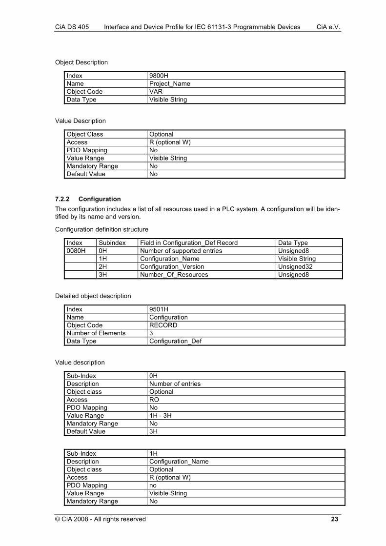
Object Description
Index 9800H Name Project_Name Object Code VAR Data Type Visible String
Value Description
Object Class Optional Access R (optional W) PDO Mapping No Value Range Visible String Mandatory Range No Default Value No
7.2.2 Configuration The configuration includes a list of all resources used in a PLC system. A configuration will be iden-tified by its name and version.
Configuration definition structure
Index Subindex Field in Configuration_Def Record Data Type 0080H 0H Number of supported entries Unsigned8 1H Configuration_Name Visible String 2H Configuration_Version Unsigned32 3H Number_Of_Resources Unsigned8
Detailed object description
Index 9501H Name Configuration Object Code RECORD Number of Elements 3 Data Type Configuration_Def
Value description
Sub-Index 0H Description Number of entries Object class Optional Access RO PDO Mapping No Value Range 1H - 3H Mandatory Range No Default Value 3H
Sub-Index 1H Description Configuration_Name Object class Optional Access R (optional W) PDO Mapping no Value Range Visible String Mandatory Range No

CiA DS 405 Interface and Device Profile for IEC 61131-3 Programmable Devices CiA e.V.
24 © CiA 2008 - All rights reserved
Default Value No
Sub-Index 2H Description Configuration_Version Object class Optional Access R (optional W) PDO Mapping no Value Range Unsigned32 Mandatory Range no Default Value no
Sub-Index 3H Description Number_Of_Resources Object class optional Access R (optional W) PDO Mapping no Value Range Unsigned8 Mandatory Range no Default Value no
7.2.3 Resources The declaration of resources provides a mechanism to allocate tasks and programs to a resource (e.g. PLC CPU). A resource will be identified by its name and version. The task handle is a refer-ence to the first task on a resource.
Resource definition structure
Index Subindex Field in Resource_Def Record Data Type 0081H 0H Number of supported entries Unsigned8 1H Resource_Name Visible String 2H Resource_Version Unsigned32 3H Number_Of_Tasks Unsigned8 4H Task_Handle Unsigned32
Detailed object description
Index 9600H - 96FFH Name Resource Object Code RECORD Number of Elements 4 Data Type Resource_Def
Value description
Sub-Index 0H Description Number of supported entries Object class Optional Access RO PDO Mapping No Value Range Unsigned8 Mandatory Range 4 Default Value No
Sub-Index 1H
CiA DS 405 Interface and Device Profile for IEC 61131-3 Programmable Devices CiA e.V.
© CiA 2008 - All rights reserved 25
Description Resource_Name Object class Optional Access R (optional W) PDO Mapping No Value Range Visible String Mandatory Range No Default Value No
Sub-Index 2H Description Resource_Version Object class Optional Access R (optional W) PDO Mapping No Value Range Unsigned32 Mandatory Range No Default Value No
Sub-Index 3H Description Number_Of_Tasks Object class Optional Access R (optional W) PDO Mapping No Value Range Unsigned8 Mandatory Range No Default Value No
Sub-Index 4H Description Task_Handle Object class Optional Access R (optional W) PDO Mapping No Value Range Unsigned32 Mandatory Range No Default Value No
7.2.4 Task A task will be identified by its name or identifier. The task types cyclic, event and timertask are supported.
Representation of the Values: cyclic = 0x0, event = 0x1, timertask = 0x2
Task definition structure
Index Subindex Field in Task_Def Record Data Type 0082H 0H Number of supported entries Unsigned8 1H Task_Name Visible String 2H Task_Identifier Unsigned32 3H Task_Types Unsigned32 4H Task_Priority Unsigned32 5H Time_Intervall Unsigned32
Detailed object description
Index 9700H - 97FFH Name Task

CiA DS 405 Interface and Device Profile for IEC 61131-3 Programmable Devices CiA e.V.
26 © CiA 2008 - All rights reserved
Object Code RECORD Number of Elements 5 Data Type Task_Def
Value description
Sub-Index 0H Description Number of supported entries Object class Optional Access RO PDO Mapping No Value Range Unsigned8 Mandatory Range No Default Value No
Sub-Index 1H Description Task_Name Object class Optional Access R (optional W) PDO Mapping No Value Range Visible String Mandatory Range No Default Value No
Sub-Index 2H Description Task_Identifier Object class Optional Access R (optional W) PDO Mapping No Value Range Unsigned32 Mandatory Range No Default Value No
Sub-Index 3H Description Task_Type Object class Optional Access R (optional W) PDO Mapping No Value Range Unsigned32 Mandatory Range No Default Value No
Sub-Index 4H Description Task_Priority Object class Optional Access R (optional W) PDO Mapping No Value Range Unsigned32 Mandatory Range No Default Value No
Sub-Index 5H Description Time_Interval
CiA DS 405 Interface and Device Profile for IEC 61131-3 Programmable Devices CiA e.V.
© CiA 2008 - All rights reserved 27
Object class Optional Access R (optional W) PDO Mapping No Value Range Unsigned32 Mandatory Range No Default Value No
7.2.5 Start/Stop (Program/Task) see /DSP-302/
7.2.6 Debugging/Monitoring see /DSP-302/

CiA DS 405 Interface and Device Profile for IEC 61131-3 Programmable Devices CiA e.V.
28 © CiA 2008 - All rights reserved
8 Appendix (informative)
8.1 Detailed description of network variable segments [DynamicChannels] NrOfSeg=36 ; --------Boolean --------- Type1=1 Dir1=ro Range1=0xA080-0xA0BF PPOffset1=0, 1 ; -------- Integer8--------- Type2=2 Dir2=ro Range2=0xA000-0xA03F PPOffset2=0 ; ------- Usigned8 -------- Type3=5 Dir3=ro Range3=0xA040-0xA07F PPOffset3=0 ; ------- Integer16 -------- Type4=3 Dir4=ro Range4=0xA0C0-0xA0FF PPOffset4=0 ; ------ Unsigned16 ------ Type5=6 Dir5=ro Range5=0xA100-0xA13F PPOffset5=0 ; ------- Integer24 -------- Type6=0x10 Dir6=ro Range6=0xA140-0xA17F PPOffset6=0 ; ------ Unsigned24 ------ Type7=0x16 Dir7=ro Range7=0xA180-0xA1BF PPOffset7=0 ; ------- Integer32 -------- Type8=4 Dir8=ro Range8=0xA1C0-0xA1FF PPOffset8=0 ; ------ Unsigned32 ------ Type9=7 Dir9=ro Range9=0xA200-0xA23F PPOffset9=0 ; ------- Integer40 -------- Type10=0x12 Dir10=ro Range10=0xA2C0-0xA2FF PPOffset10=0 ; ------ Unsigned40 ------ Type11=0x18 Dir11=ro Range11=0xA280-0xA2BF PPOffset11=0 ; ------- Integer48 -------- Type12=0x13 Dir12=ro Range12=0xA340-0xA37F PPOffset12=0
; ------ Unsigned48 ------ Type13=0x19 Dir13=ro Range13=0xA300-0xA33F PPOffset13=0 ; -------- Integer56 -------- Type14=0x14 Dir14=ro Range14=0xA3C0-0xA3FF PPOffset14=0 ; ------ Unsigned56 ------ Type15=0x1A Dir15=ro Range15=0xA380-0xA3BF PPOffset15=0 ; -------- Integer64 -------- Type16=0x15 Dir16=ro Range16=0xA400-0xA43F PPOffset16=0 ; ------ Unsigned64 ------ Type17=0x1B Dir17=ro Range17=0xA440-0xA47F PPOffset17=0 ; ----------- Float ----------- Type18=8 Dir18=ro Range18=0xA240-0xA27F PPOffset18=0 ; -------- Boolean: -------- Type19=1 Dir19=rww Range19=0xA500-0xA53F PPOffset19=0, 1 ; --------- Integer8 --------- Type20=2 Dir20=rww Range20=0xA480-0xA4BF PPOffset20=0 ; ------- Unsigned8 ------ Type21=5 Dir21=rww Range21=0xA4C0-0xA4FF PPOffset21=0 ; -------- Integer16 -------- Type22=3 Dir22=rww Range22=0xA540-0xA57F PPOffset22=0 ; ------ Unsigned16 ------ Type23=6 Dir23=rww Range23=0xA580-0xA5BF PPOffset23=0 ; -------- Integer24 -------- Type24=0x0x10 Dir24=rww Range24=0xA5C0-0xA5FF PPOffset24=0
; ------ Unsigned24 ------ Type25=0x16 Dir25=rww Range25=0xA600-0xA63F PPOffset25=0 ; -------- Integer32 -------- Type26=4 Dir26=rww Range26=0xA640-0xA67F PPOffset26=0 ; ------ Unsigned32 ------ Type27=7 Dir27=rww Range27=0xA680-0xA6BF PPOffset27=0 ; -------- Integer40 -------- Type28=0x12 Dir28=rww Range28=0xA740-0xA77F PPOffset28=0 ; ------ Unsigned40 ------ Type29=0x18 Dir29=rww Range29=0xA700-0xA73F PPOffset29=0 ; -------- Integer48 -------- Type30=0x13 Dir30=rww Range30=0xA7C0-0xA7FF PPOffset30=0 ; ------ Unsigned48 ------ Type31=0x19 Dir31=rww Range31=0xA780-0xA7BF PPOffset31=0 ; -------- Integer56 -------- Type32=0x14 Dir32=rww Range32=0xA840-0xA87F PPOffset32=0 ; ------ Unsigned56 ------ Type33=0x1A Dir33=rww Range33=0xA800xA83F PPOffset33=0 ; -------- Integer64 -------- Type34=0x15 Dir34=rww Range34=0xA880-0xA8BF PPOffset34=0 ; ------ Unsigned64------- Type35=0x1B Dir35=rww Range35=0xA8C0-0xA8FF PPOffset35=0 ; ----------- Float ----------- Type36=8 Dir36=rww Range36=0xA6C0-0xA6FF PPOffset36=0

CiA DS 405 Interface and Device Profile for IEC 61131-3 Programmable Devices CiA e.V.
© CiA 2008 - All rights reserved 29
8.2 IEC 61131-3 object dictionary overview The following table shows all objects, affected by these specification.
Index (hex)
Object Name Type Acc. M/O
0080H DEFSTRUCT Configuration_Name
0081H DEFSTRUCT Resource_Def
0082H DEFSTRUCT Task_Def
1000H VAR Device type Unsigned32 RO M
9501H RECORD Configuration Configuration_Def RW O
9600H RECORD 1st Resource Resource_Def RW O
9601H RECORD 2nd Resource Resource_Def RW O
:
96FFH RECORD 255th Resource Resource_Def RW O
9700H RECORD 1st Task Task_Def RW O
9701H RECORD 2nd Task Task_Def RW O
:
97FFH RECORD 255th Task Task_Def RW O
9800H VAR Project_Name Visible String RW O
A000H ARRAY 1st Dynamic Integer8 Integer8 RO O
:
A03FH ARRAY 64th Dynamic Integer8 Integer8 RO O
A040H ARRAY 1st dynamic Unsigned8 Unsigned8 RO O
:
A07FH ARRAY 64th Dynamic Unsigned8 Unsigned8 RO O
A080H ARRAY 1st Dynamic Boolean Boolean RO O
:
A0BFH ARRAY 64th Dynamic Boolean Boolean RO O
A0C0H ARRAY 1st Dynamic Integer16 Integer16 RO O
:
A0FF0H ARRAY 64th Dynamic Integer16 Integer16 RO O
A100H ARRAY 1st Dynamic Unsigned16 Unsigned16 RO O

CiA DS 405 Interface and Device Profile for IEC 61131-3 Programmable Devices CiA e.V.
30 © CiA 2008 - All rights reserved
:
A13FH ARRAY 64th Dynamic Unsigned16 Unsigned16 RO O
:
:
A440H ARRAY 1st Dynamic Unsigned64 Unsigned64 RO O
:
A47FH ARRAY 64th Dynamic Unsigned64 Unsigned64 RO O
A480H ARRAY 1st Dynamic Integer8 Integer8 RWW O
:
A4BFH ARRAY 64th Dynamic Integer8 Integer8 RWW O
:
:
A8C0H ARRAY 1st Dynamic Unsigned64 Unsigned64 RWW O
:
A8FFH ARRAY 64th Dynamic Unsigned64 Unsigned64 RWW O
Table 10: List of object dictionary entries

CiA DS 405 Interface and Device Profile for IEC 61131-3 Programmable Devices CiA e.V.
© CiA 2008 - All rights reserved 31
8.3 Example DCF file This is not a complete DCF. Only several specific entries for the DS405 are listed.
[DeviceInfo] ... DynamicChannelsSupported=3 ... [DynamicChannels] ; optional since DynamicChannelsSupported=3 NrOfSeg=36 ; see application notes Type1=1 Dir1=ro Range1=0xA080-0xA0BF PPOffset1=0,1 ... Type36=8 Dir36=rww Range36=0xA6C0-0xA6FF PPOffset36=0 ... [OptionalObjects] 1=0xA000 ... [A000] ; Integer8 RO SubNumber=3 ParameterName=Integer8_RO_Variables ObjectType=8 [A000Sub0] ParameterName=NrOfSupportedObjects ObjectType=0x7 DataType=0x0005 AccessType=ro DefaultValue=2 PDOMapping=0 [A000Sub1] ParameterName=<NameOfProcessVariable1> ObjectType=0x7 DataType=0x0002 AccessType=ro DefaultValue= PDOMapping=1 [A000Sub2] ParameterName=<NameOfProcessVariable2> ObjectType=0x7 DataType=0x0002 AccessType=ro DefaultValue= PDOMapping=1 ...
8.4 Application notes 8.4.1 Network variables The usage of the dynamic index assignment of the network variables implies, that the object dic-tionary area contains arrays with gaps. For example an array may have two sub-objects 1 and 5.

CiA DS 405 Interface and Device Profile for IEC 61131-3 Programmable Devices CiA e.V.
32 © CiA 2008 - All rights reserved
8.4.2 Data type representation issues In chapter 4.2 the internal data type representation is specified to be partially CANopen non-compliant. If this happens, there may be different data representation of the same data values.
Example:
A PLC may have a byte ordering opposite to CANopen. When transferring a network variable of data type Unsigned16 with value 1 via a PDO according to 4.2 the process picture will contain the following value:
ID byte 0 byte 1
abc 1 0
byte 0 byte 1
0 1
PDO
Protocol stack
Process image
0001 h = 1dApplication value
0001 h = 1dInterpretation by other
devices according to
CANopen encoding rules
Figure 24: Data representation with PDO on CANopen non-compliant PLCs
When transferring the same value via SDO, there is another situation:
ID protocol byte 0 byte 1
xyz xyz 0 1
byte 0 byte 1
0 1
SDO
Protocol stack
Process image
0001 h = 1dApplication value
0100 h = 256dInterpretation by other
devices according to
CANopen encoding rules
Figure 25: Data representation with SDO on CANopen non-compliant and compliant PLCs
It is the responsibility of the application / user to consider this. The manufacturer of a PLC may decide to make the byte-re-ordering as an own task upon the protocol stack. This will avoid the problem, but will need much more system resources.

CiA DS 405 Interface and Device Profile for IEC 61131-3 Programmable Devices CiA e.V.
© CiA 2008 - All rights reserved 33
8.4.3 EDS The usage of "DynamicChannelsSupported=3" implies not to support all possible CANopen data types with a device. If the device supports only some of these data types (e.g. BOOL, 1-, 2- and 4 Byte wide types), this can be coded by using the section "DynamicChannels".
It is not allowed to redefine the section "DynamicChannels" of a 405 Profile. Tools are allowed to presuppose the objects as defined in these specification and it is recommended that tools, support the 405 Profile, do not interpret data types other than specified. A reason to enter the section "Dy-namicChannels" in a EDS/DCF is to support tools without knowledge of the 405 Profile (e.g. DSP-302 Tools) or to give information, what data types are supported or to supply the information of the implemented size of the segments.
For these reasons it is strongly recommended to include the section “DynamicChannels” in the EDS.
8.4.4 Tool integration This mechanism allows all kind of tools to use the Project files. Users can work with programming environments, debugging tools and project planing tools or only simple node specific configuration tools. Each tool has full access to all information. Further there is no consistency problem between different files.
The locking mechanism is available on every disk operating system used in practice.
Definition of variables may be done in the Programming System. In that case the Network Configu-ration has to be informed about the name, type and address of these variables, since the Network Configuration is responsible for setting-up the appropriate communication channels for transferring the data contents. The other possibility is the generation of variables in the Network Planning Sys-tem. This is useful on setting-up a network with distributed intelligence, where the interface be-tween the separate processes has to be defined. In that case a possibility is required to transfer information about the generated variables to the Programming System of each programmable de-vice of that network.
Chapter 6 specifies the data exchange via DCF according to Figure 26.
IEC 61131CANopenNetwork
ConfigurationDCF
Figure 26: Information exchange via DCF
Some programming systems may not support DCF file formats. In practice it even may be not pos-sible to extend them. But normally they will provide a possibility of data exchange in any other file format. For example this may be something like an include file written in IEC 61131-3 syntax itself (such as DTY). For fulfilling the specification in chapter 6 it is possible to use a converter module as shown in Figure 27.
ConverterIEC 61131CANopen
Network
ConfigurationDCFxyz
Figure 27: Data exchange using converter module

CiA DS 405 Interface and Device Profile for IEC 61131-3 Programmable Devices CiA e.V.
34 © CiA 2008 - All rights reserved
Version 1.0 of DSP-405 defined mechanisms for data exchange via DCF and a file format called NVX. For compatibilty reasons the usage of NVX can be interpreted in a way, that the converter is part of the programming system as well as of the Network Configuration System. This is illustrated in Figure 28.
IEC 61131
DCFxyz
IEC 61131CANopen
Network
ConfigurationDCF
Conv.
Part
CANopen
Network
Configuration
Figure 28: Compatibility for NVX format
To allow the denotation of a device specific tool already by the device manufacturer the EDS may contain a description, which tools are to be used. On creating a DCF from that EDS, this tool de-scription will be copied.
The description start with a section [Tools] containing the entry Items with the number of tools supported. Each tool is described in a section [Toolx] with x as decimal counter (1..Items). These sections contain the entries Name and Command giving the symbolic name and the concrete command. Further entries may exist. Manufacturers are responsible to avoid naming collisions. Command line parameters are not specified here. They depend on the converters.
The example shows a converter
[Tools] Items=1 [Tool1] Name=Convert DCF to DTY Command=DCF2DTY $DCF $NAME.DTY

CiA DS 405 Interface and Device Profile for IEC 61131-3 Programmable Devices CiA e.V.
© CiA 2008 - All rights reserved 35
8.5 IEC 61131-3 sample code To give a better impression of how the IEC 61131-3 defined items will be used in a typical applica-tion, here is one (non-normative) sample program:
PROGRAM HeatControl VAR_EXTERN (* How to map variables between process image and CANopen will *) (* be very system dependent, this is just one possible way *) Temperature: CIA405INT24; VentilatorSpeed: CIA405UINT48; END_VAR VAR_GLOBAL MaxTemperature: DINT := 21; Slow : ULINT := 300; (* whatever unit *) Fast : ULINT := 800; (* same unit *) END_VAR LD Temperature CIA405INT24_TO_DINT GT MaxTemperature JMPC cooler (* seems not to hot, so run ventilator slow *) LD Slow ULINT_TO_CIA405UINT48 ST VentilatorSpeed JMP go_on cooler: (* seems to be hot, run ventilator faster *) LD Fast ULINT_TO_CIA405UINT48 ST VentilatorSpeed go_on: (* rest of program *) END_PROGRAM
8.6 Implementation models for IEC 61131-3 data type support Data types CIA405INT24 etc. as mentioned before are not standard with IEC 61131-3. How these are made available to the user is left to implementation, the following chapter describes several possible options. All these models are non-normative, serving only for a better understanding
8.6.1 Native support One possible implementation is to integrate support for these data types defined above into the IEC 61131-3 programming system. No conversions should be necessary then, the new data types can be integrated into the IEC 61131-3 hierarchy of data types, allowing all built-in instructions and many overloaded system functions to be used for these data types (ADD, EQ, MAX, ...).
Problem: Some effort to implement.
8.6.2 Padding to next best match The new data types may be defined by using the closest matching IEC 61131-3 native type, e.g. TYPE CIA405INT48: LINT; END_TYPE;
Problem: Memory space is wasted. Value of IEC 61131-3 may exceed limits of CANopen represen-tation. Which instance shall handle this and how? Necessary padding bytes might impose prob-lems on IEC 61131-3 memory mapping (e.g. process image).

CiA DS 405 Interface and Device Profile for IEC 61131-3 Programmable Devices CiA e.V.
36 © CiA 2008 - All rights reserved
8.6.3 Using arrays or struct The new types may be defined using a array (or structure) of individual bytes:
TYPE CIA405INT48: array[1..6] of BYTE; END_TYPE;
or
TYPE CIA405INT48: STRUCT b1,b2,b3,b4,b5,b6: BYTE; END_TYPE;
Applications using only data types and conversion functions as defined in chapters before can be truly portable to different systems, no matter which of these three implementation models be used. Applications using details depending on any of these implementations (applying an ADD to one of these types, accessing individual elements of this array or relying on out-of-range behaviour) might not be portable.


![Autdev Interface [Autorship + Webdevelopment + Interface]](https://img.pdfslide.us/doc/110x75/568bd8ee1a28ab2034a52641/autdev-interface-autorship-webdevelopment-interface.jpg)