Embed Size (px)
Citation preview
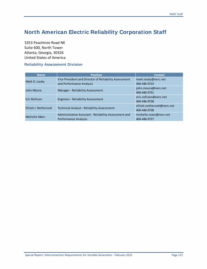
3353 Peachtree Road NE Suite 600 North Tower
Atlanta GA 30326 404-446-2560 | wwwnerccom
2012 Special Assessment Interconnection Requirements for Variable Generation
September 2012
ii Interconnection Requirements for Variable Generation - September 2012
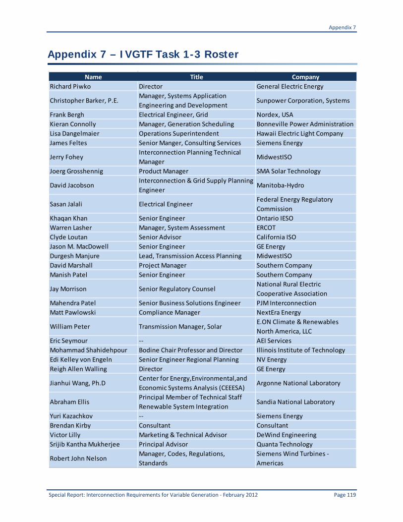
Report Contributors IVGTF Task Force 1-3 Chair Richard Piwko Lead Authors for Report Chapters Abraham Ellis Reigh Walling Bob Zavadil David Jacobson Richard Piwko Contributing Authors Mahendra Patel Daniel Brooks Bob Nelson Jason MacDowell Chris Barker Edi von Engeln Eric Seymour Leo Casey Eric John William Peter Warren Lasher Clyde Loutan Lisa Dangelmaier Eric Seymour Mike Behnke Reviewers This report was reviewed and revised per comments received from the IVGTF Task 1-3 members the IVGTF Leadership Team and the NERC Planning Committee See Appendix C for a complete list of Task Force members and affiliations
Interconnection Requirements for Variable Generation - September 2012 ii
Table of Contents
Executive Summary 1
1 Introduction 12
2 Reactive Power and Voltage 19
3 Performance During and After Disturbances 39
4 Active Power Control Capabilities 62
5 Harmonics and Subsynchronous Interaction 80
6 Models for Facility Interconnection Studies 85
7 Communications between Variable Generation Plants and Grid Operators 90
Appendix 1 ndash Disturbance Performance Requirements from International Standards and Grid Codes 98
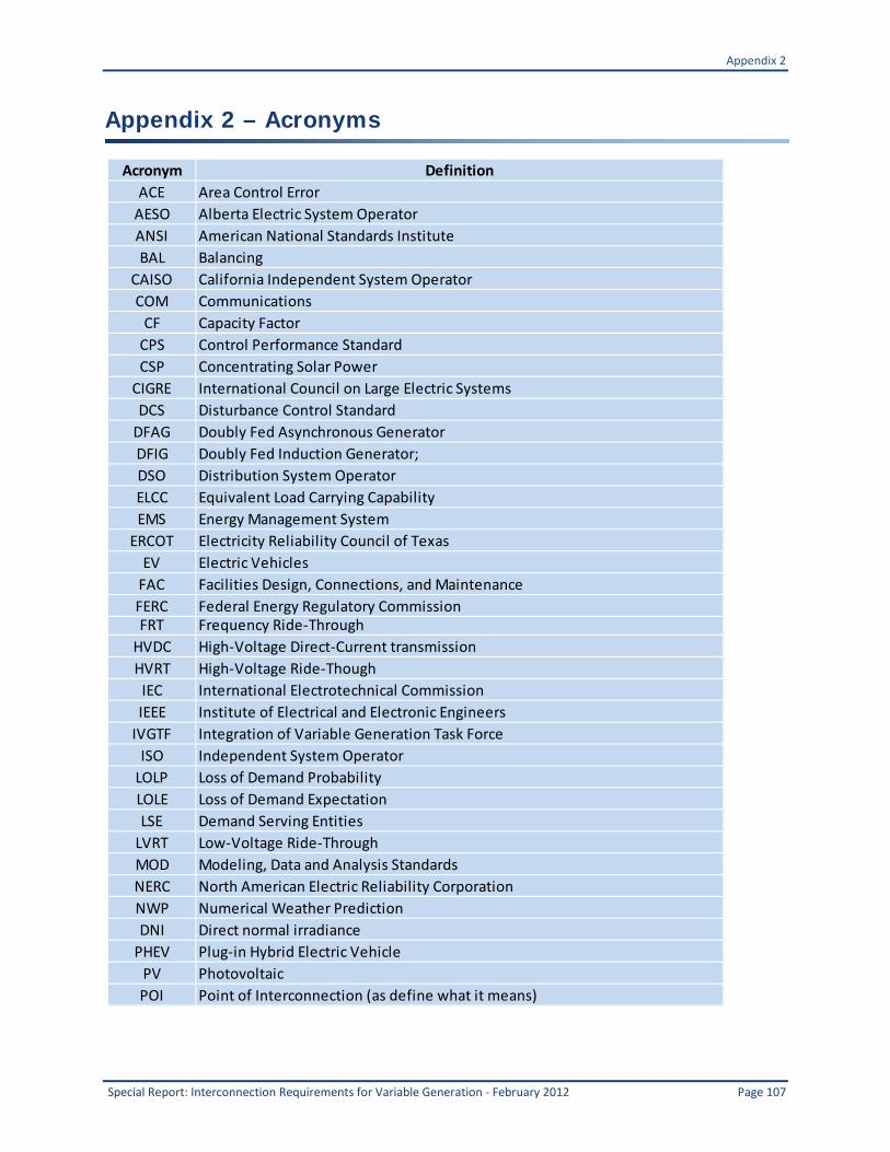
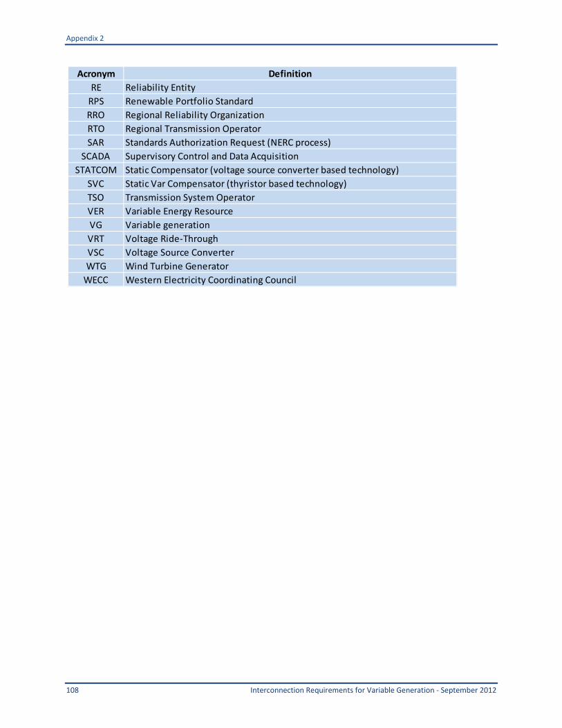
Appendix 2 ndash Acronyms 107
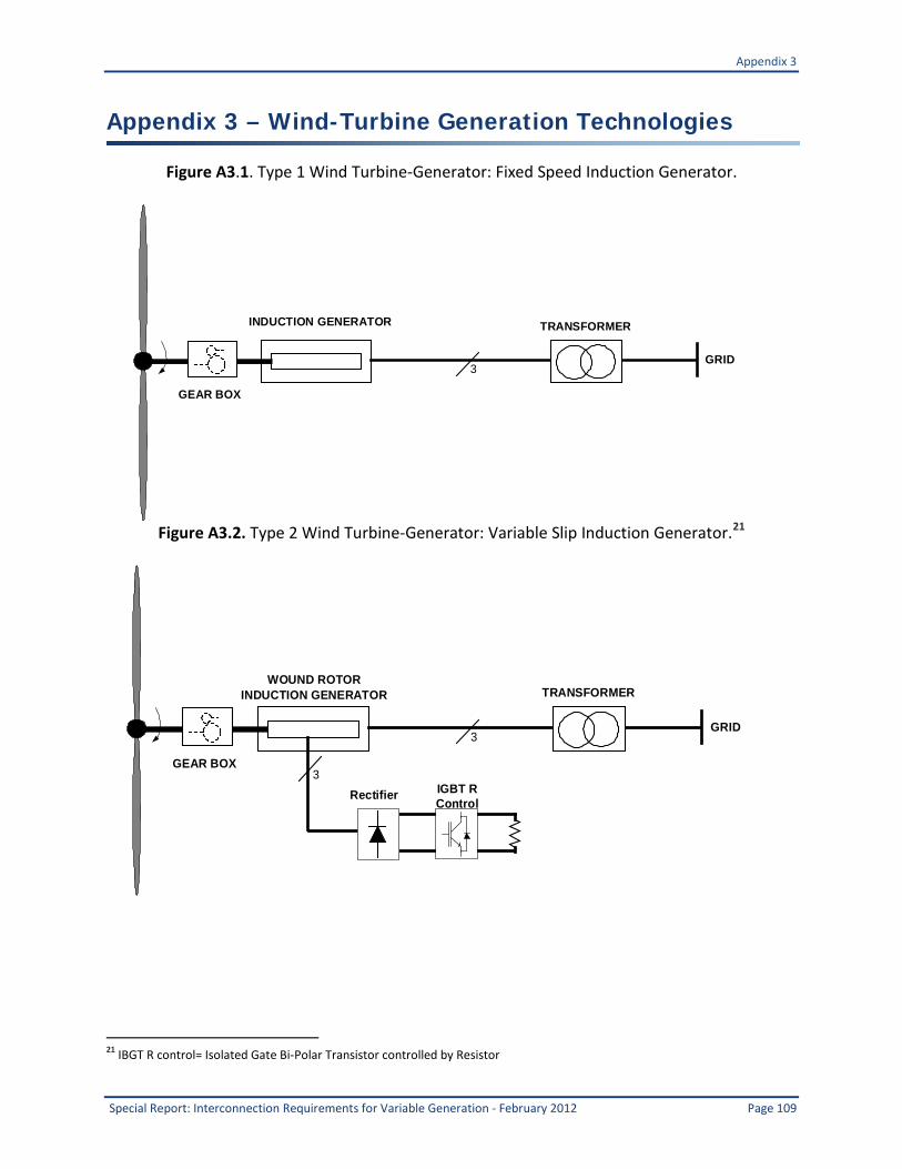
Appendix 3 ndash Wind-Turbine Generation Technologies 109
Appendix 4 ndash Further Reading 111
Appendix 5 ndash Review of Utility Facility Connection Requirements or Grid Codes 112
Appendix 6 ndash Summary of Existing Reactive Power Standards 117
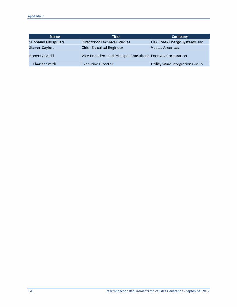
Appendix 7 ndash IVGTF Task 1-3 Roster 119
North American Electric Reliability Corporation Staff 121
Executive Summary
1 Interconnection Requirements for Variable Generation - September 2012
Executive Summary Many of NERCrsquos existing interconnection standards and procedures have been based on technical characteristics and physical capabilities of traditional power generation resources that employ synchronous generators With the global trend toward renewable energy the penetration of wind and solar generation is rapidly increasing in many power grids under NERCrsquos jurisdiction Variable generation comprises any power generating facility in which the source of the energy is not dispatchable Wind and solar generation are the most common types of variable generation although ongoing research may lead to increased utilization of tidal wave ocean thermal and other new energy sources Some common characteristics of wind plants and solar photovoltaic (PV) plants include1
bull The energy source is variable influenced by atmospheric conditions and predicted by day-ahead and short-term forecasting
bull Variable generation plants are often comprised of multiple individual ldquogeneratorsrdquo connected together and operated in a coordinated manner
bull To a large extent the power sources (such as wind turbines or solar panels) are connected to the electrical network via power electronics rather than synchronous machines
bull Responses to system disturbances are primarily determined by control functions not the inherent electromechanical dynamics of synchronous machines
Summary of Recommendations This task force was asked to make recommendations for how NERC Interconnection procedures and standards should be enhanced to address voltage and frequency ride-through reactive and real power control and frequencyinertial response criteria in light of the evolving range of technical characteristics and physical capabilities of variable generation equipment This report documents the results of that project Although many readers may prefer a simple one- or two-page summary that explains everything about what rules and procedures need to be modified and how to do it the task force found that the issues are very complex and do not lend themselves to brief unqualified bullet points Instead each recommendation must be considered in light of the technical reasoning behind it
1 Small-scale solar projects connected to the distribution system such as roof-top solar PV on homes or solar panels on
distribution circuits (and connected to distribution secondary circuits) are not included with solar PV as discussed in this report
Executive Summary
Interconnection Requirements for Variable Generation - September 2012 2
The remainder of this executive summary gives an overview of the recommendations in each of the following technical subject areas Subsequent chapters of the report provide background context and reasoning behind the recommendations
bull Reactive Power and Voltage Control Chapter 2
bull Performance During and After Disturbances Chapter 3
bull Active Power Control Chapter 4
bull Harmonics and Subsynchronous Interactions Chapter 5
bull Models for Facility Interconnection Studies Chapter 6
bull Communications Between Plants and Operators Chapter 7
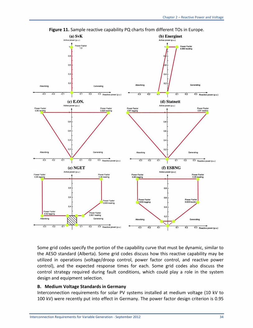
Reactive Power and Voltage Control Recommendations for Modification of Existing NERC Standards NERC should consider revisions to FAC and VAR standards to ensure that reactive power requirements for all generators are addressed in a technically clear and technology-neutral manner Where technically justified Regional differences of these requirements may be necessary to maintain reliability As with all new or changing requirements appropriate consideration should be given to the applicability of existing generators Suggested updates are as follows
bull Consider adding an Appendix to FAC-001 to clarify that interconnection standards for reactive power must cover specifications for minimum static and dynamic reactive power requirements at full power and at partial power and how terminal voltage should affect the power factor or reactive range requirement (see Section 0 below for technical guidelines)
bull Consider modifying VAR-001 to include the term ldquoplant-level voltvar controllerrdquo (in addition to ldquoAVRrdquo) which is more appropriate for variable generation Specific recommended changes are underlined below ldquoVAR-001 R4 Each Transmission Operator shall specify a voltage or Reactive Power schedule at the interconnection between the generator facility and the Transmission Ownerrsquos facilities to be maintained by each generator The Transmission Operator shall provide the voltage or Reactive Power schedule to the associated Generator Operator and direct the Generator Operator to comply with the schedule in automatic voltage control mode (AVR or plant-level voltvar regulator in service and controlling voltage)rdquo
A large amount of variable generation including most of the solar PV deployment will be relatively small plants with capacity below the threshold specified in the existing NERC Registry Criteria and connected at voltages below 100 kV2
2 The above are general criteria only The Regional Entity considering registration of an organization not meeting (eg smaller
in size than) the criteria may propose registration of that organization if the Regional Entity believes and can reasonably demonstrate that the organization is a bulk power system owner or operates or uses bulk power system assets and is
This includes residential and commercial
Executive Summary
3 Interconnection Requirements for Variable Generation - September 2012
systems as well as larger plants connected to the distribution or sub-transmission system Accordingly addressing many of these issues would be beyond NERCrsquos current scope To the extent that these systems in aggregate can affect the reliability of the bulk grid it is recommended that NERC work with the affected entities in different regionsmdashincluding state agencies RTOs and vertically integrated utilitiesmdashto develop appropriate guidelines practices and requirements to address issues impacting the reliability of the bulk electric system Any prospective guideline practice or requirement addressing reactive requirements for smaller plants should recognize that distribution-connected variable generation plants have traditionally been operated in power factor control mode General Recommendations for Standards Development and Reconciliation For the most part existing NERC and FERC Interconnection standards were developed with a class of equipment in mind (synchronous generators) and do not fully define performance requirements for reactive power support This has resulted in unclear inconsistent and sometimes inappropriate interconnection reactive power requirements for generators especially variable generation Specific recommendations are as follows
bull NERC should promote greater uniformity and clarity of reactive power requirements contained in connection requirements that Transmission Owners have issued pursuant to FAC-001 NERC FERC and other applicable Regional standards should be reconciled
bull NERC should consider initiating a Standards Authorization Request (SAR) to establish minimum reactive power capability standards for interconnection of all generators and provide clear definitions of acceptable control performance (see Section 283 for technical guidelines)
Technical Guidelines for Specification of Reactive Power Requirements Variable generation technologies are technically capable of providing steady-state and dynamic reactive power support to the grid Based on a review of best practices and operating experience we offer the following technical guidelines for specification of reactive power capability and control requirements for interconnection of generating plants to the transmission system (these guidelines are discussed in greater detail in Section 283)
bull Applicability Generator interconnection requirement for reactive power should be clearly established for all generator technologies NERC should consider giving transmission planners some discretion to establish variance based on the characteristics of their transmission system and the size of the generator
bull Specification of Reactive Range The reactive range requirement should be defined over the full output range and it should be applicable at the point of connection
material to the reliability of the bulk power system Similarly the Regional Entity may exclude an organization that meets the criteria described above as a candidate for registration if it believes and can reasonably demonstrate to NERC that the bulk power system owner operator or user does not have a material impact on the reliability of the bulk power system The reasonableness of any such demonstration will be subject to review and remand by NERC itself or by any agency having regulatory or statutory oversight of NERC as the ERO (eg FERC or appropriate Canadian authorities)
Executive Summary
Interconnection Requirements for Variable Generation - September 2012 4
bull Impact of System Voltage on Reactive Power Capability It should be recognized that system voltage level affects a generating plantrsquos ability to deliver reactive power to the grid and the power systemrsquos requirement for reactive support
bull Specification of Dynamic Reactive Capability The standard should clearly define what is meant by ldquoDynamicrdquo Reactive Capability by specifying the portion of the reactive power capability that is expected to be dynamic A prospective standard should specify the minimum performance characteristic of the response in terms of response time granularity (maximum step size) and repeatability (close-open-close cycling capability)
bull Definition of Control Performance Expected voltvar control performance should be specified including minimum control response time for voltage control power factor control and reactive power control An interim period for the application of precisely defined control capabilities should be considered
bull Effect of Generator Synchronization on System Voltage Synchronization of generators to the grid should not cause excessive dynamic or steady-state voltage change at the point of connection A 2 percent limit may be considered as a baseline
bull Special Considerations NERC should investigate whether transmission operators can under some conditions allow variable generating plants to operate normally or temporarily at an active power level where dynamic reactive capability is limited or zero
bull Technical Alternatives for Meeting Reactive Power Capability The reactive power requirements should be applicable at the point of interconnection
bull Commissioning Tests Commissioning tests which are part of the interconnection process often include a test to demonstrate plant compliance with reactive power capability requirements
Performance During and After Disturbances Applicable Plants The scope of PRC-024-1 should be broadened to cover smaller plant sizes The current proposal of 75 MVA will miss many variable generator facilities that could impact the Bulk Electric System It is suggested that the scope be broadened to cover all projects under a Large Generator Interconnection Agreement (LGIA) or all projects greater than 20 MW Another option is to extend the scope to any project greater than 10 MW in order to provide coverage for plants not included under IEEE 1547 This IVGTF task team could not come to a consensus on the exact plant threshold (10 vs 20 MW or MVA) It is recommended that industry decide the appropriate threshold as Regional differences may be justified3
See Section 14 for further discussion on this topic
3 On June 21 2012 FERC proposed to approve NERCrsquos Revised Definition for Bulk Electric System which included thresholds of
20 MW for individual facilities and 75 MW for aggregate facilities FERC dockets RM12-6-00 and RM12-7-000 and FERC Order 743 and 743-A cover generator thresholds in greater detail
Executive Summary
5 Interconnection Requirements for Variable Generation - September 2012
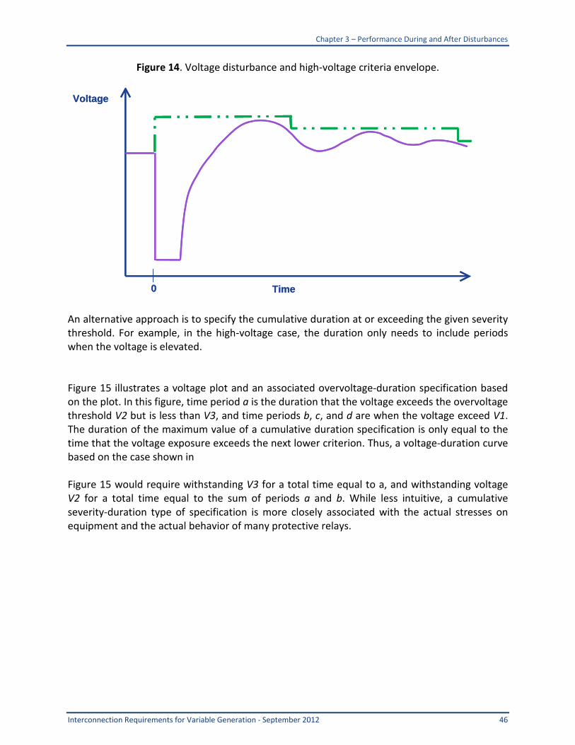
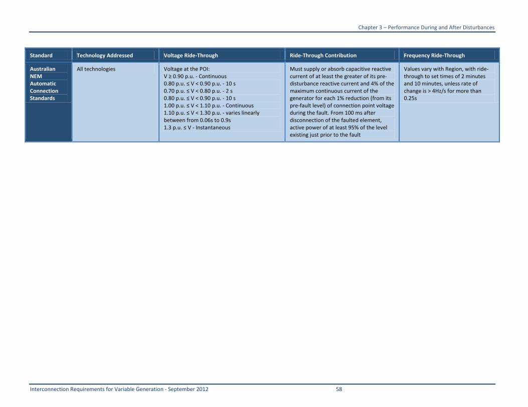
Applicability should depend on total plant rating and should not be based on individual unit size Disturbance Ride Through Fault ride-through and frequency ride-through capability of generators will be covered by the NERC standards under development TPL-001-2 will cover the planning assessment for new and existing generators to ensure that grid performance reliability standards are met PRC-024-1 will provide additional clarity to the generator industry in terms of uniform requirements No additional requirements are needed for FAC-001-0 It is suggested that ride-through plots be provided that specify both high- and low-voltage ride-through requirements It is recommended that the zero voltage ride-through should be equal to the three-phase fault clearing time on the network The zero voltage ride-through is up to 9 cycles but may be less depending on the clearing time This should be made explicit in any requirement PRC-024 should clearly define performance requirements for unbalanced and balanced faults The specification of voltage magnitude should define what voltage metric is applicable Voltage disturbance performance requirements particularly high-voltage ride-through should use the severity-cumulative duration form of specification to avoid unnecessary increase of VER plant costs to meet voltage disturbance durations that will never occur in practice It is not suggested that a NERC-wide requirement be mandated for riding through a rate of frequency change If a standard is desired by individual operators a rate-of-change ride-through requirement of 25 Hzs appears adequate (This rate of frequency change is stipulated in the current draft of PRC-024) There may be some Regional differences where at least 40 Hzs is required PRC-024 should define the performance required during and after disturbances and should make clear and unambiguous statements as to what remaining ldquoconnectedrdquo entails It is not recommended that active power be required during a voltage disturbance unless there is a reliability concern The sourcing of reactive power during a severe fault should instead be given priority over real power delivery and the magnitude of reactive power should be consistent with pre-fault reactive power capability The capability to supply reactive current during a fault varies with technology and product offerings and so a market to incentivize but not require the increased sourcing of reactive current during a voltage dip is recommended Disturbance performance requirements including PRC-024 should indicate the maximum level of transmission contingency (eg N-1-1) for which a plant should be required to ride through Disturbance performance requirements such as PRC-024 should clearly define any requirement for repeated disturbances Transmission-interconnected VER should not have any active anti-islanding functions enabled unless these functions are properly coordinated with all applicable stakeholders so that these functions do not detract from bulk transmission system transient or dynamic stability
Executive Summary
Interconnection Requirements for Variable Generation - September 2012 6
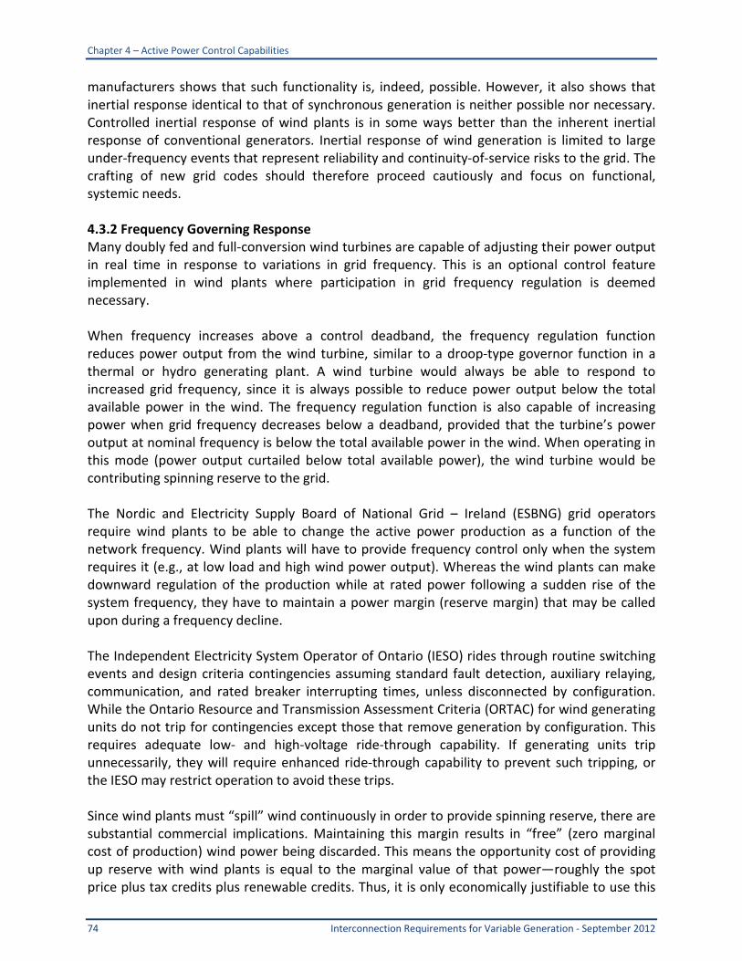
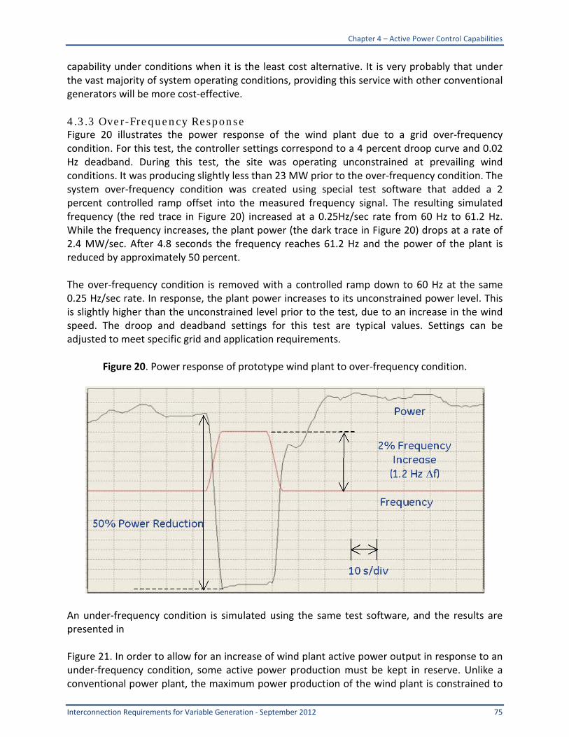
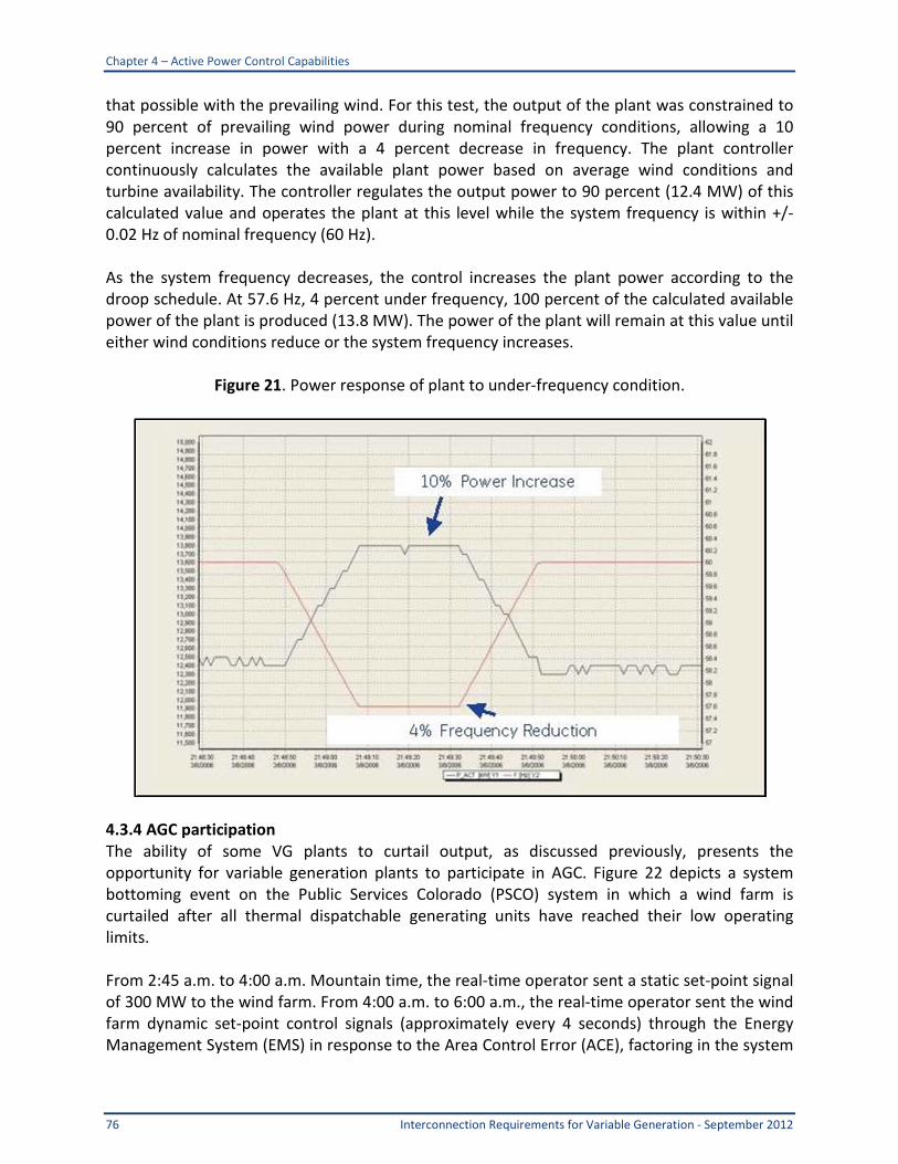
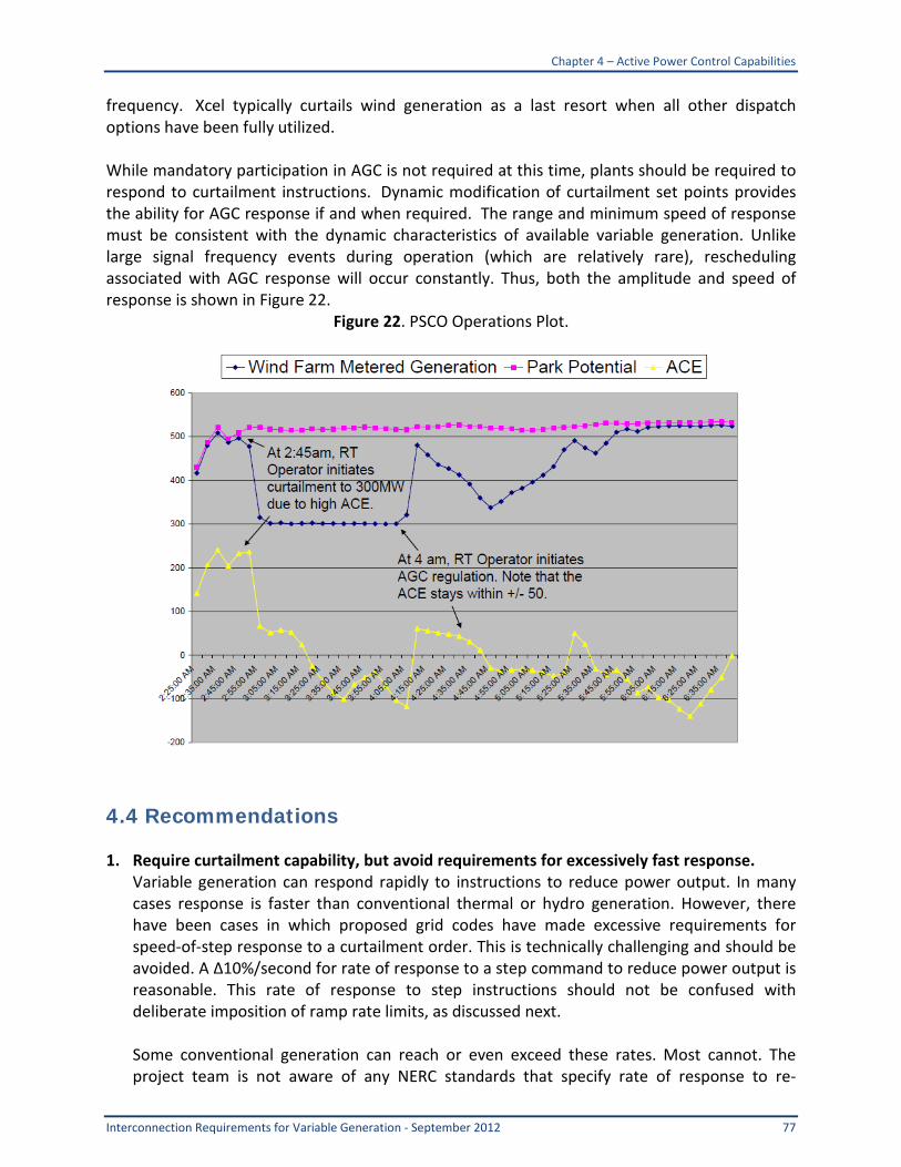
Power Recovery It is not necessary to specify in a standard a detailed power recovery characteristic for variable generators Detailed accurate models provided by the Generator Owner will be sufficient for interconnection studies If performance criteria are not met then the Transmission OwnerPlanner will work with the Generator Owner to develop a mitigation plan Recovery After Blackout It is reasonable to clarify the restart expectations of a generator facility following a disturbance In some cases the Transmission Operator provides a signal to the facility that prohibits automatic restarting after a severe grid event FAC-001 could be modified to include a facility connection requirement to address generator facility restarting Standards for manufactured equipment Current solar PV inverters designed to comply with IEEE 1547 are required to provide anti-islanding capability and disconnection requirements that are not compatible with the fault ride through requirements recommended here Although individual inverters may have capacities on the order of 500kW utility scale PV plants may have hundreds of these units and hence have a plant capacity of upwards of 100 MW Furthermore the inverters are listed to UL-1741 which is based on the requirements of IEEE 1547 This report recommends that new standards are proposed for utility scale PV plants in order to drive the industry toward the adoption of new inverter specifications testing and certification Active Power Control Capabilities Require curtailment capability but avoid requirements for excessively fast response Variable generation can respond rapidly to instructions to reduce power output In many cases response is faster than conventional thermal or hydro generation However there have been cases where proposed grid codes have made excessive requirements for speed of step response to a curtailment order This is technically challenging and should be avoided A change (Δ) 10 percent ()s for rate of response to a step command to reduce power output is reasonable This rate of response to step instructions should not be confused with deliberate imposition of ramp rate limits as discussed next Active power considerations are not driving reliability requirements at this time Some conventional generation can reach or even exceed these rates Most cannot The project team is not aware of any NERC standards that specify rate of response to re-dispatch commands (of which curtailment is a subset) in this time frame Typically plants must respond to economic re-dispatch within minutes Mechanisms such as markets or other incentives to encourage rapid rate of response from all generating resources should be considered Require capability to limit rate of increase of power output Variable generation plants should be required to have the capability to limit the rate of power increase This type of up ramp rate control capability has been required in some other systems This function should include the ability to be enabled and disabled by instruction from Transmission Operator Balancing Authority or Reliability Coordinator Plants must be able to
Executive Summary
7 Interconnection Requirements for Variable Generation - September 2012
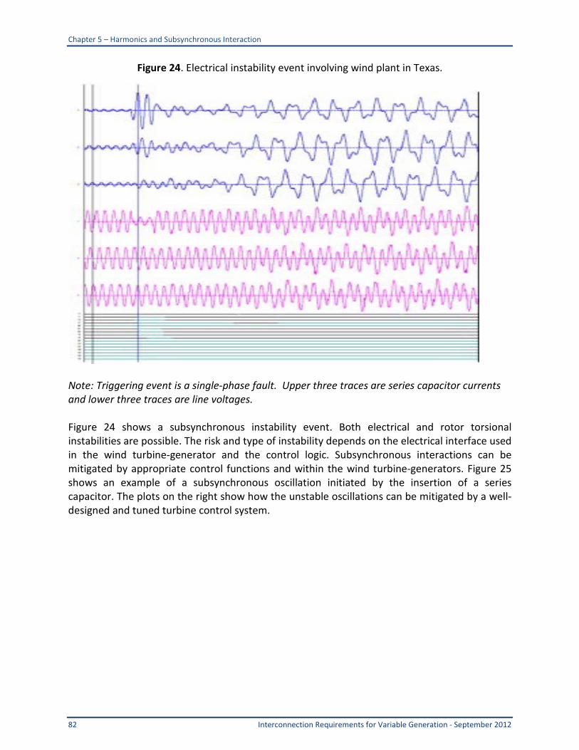
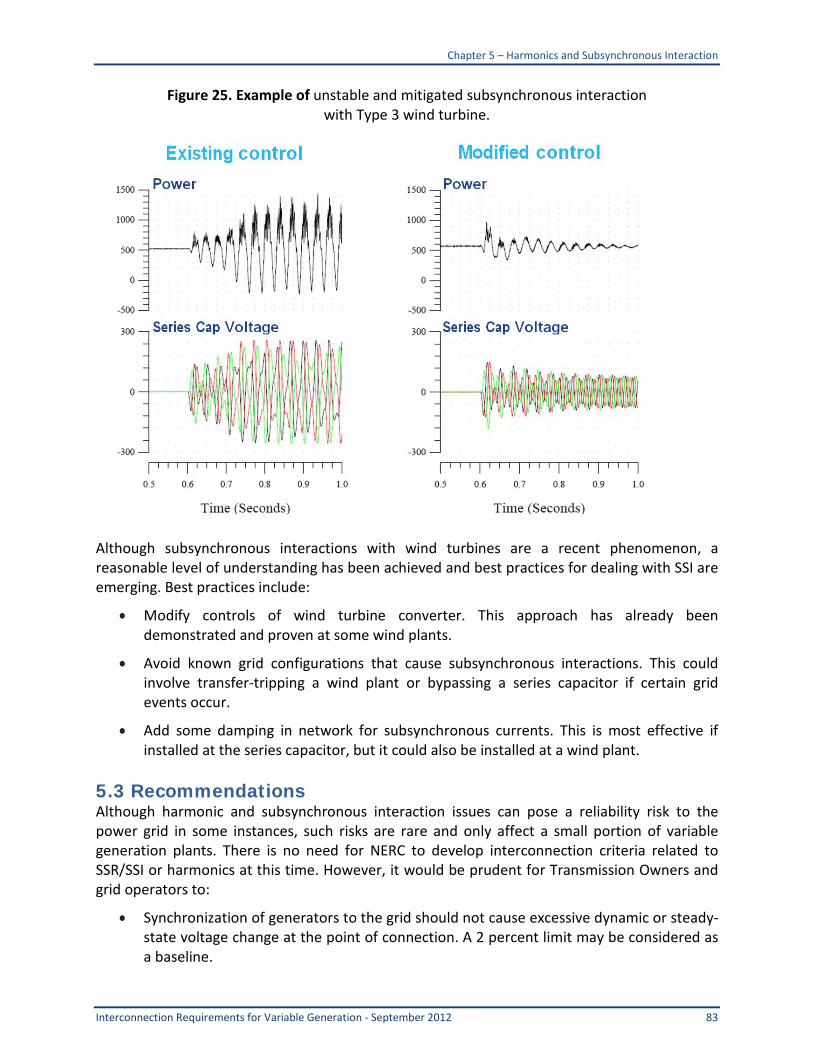
accept commands to enable pre-selected ramp rate limits Plants should be designed with recognition that ramp rate limits should not be required under all operating conditions It should not be required that variable generation plants limit power decreases due to declines in wind speed or solar irradiation (ie down ramp rate limits) However limits on decrease in power output due to other reasons including curtailment commands shut-down sequences and responses to market conditions can be reasonably required Encourage or mandate reduction of active power in response to high frequencies Variable generation plants should be encouraged to provide over-frequency droop response of similar character to that of other synchronous machine governors Consider requiring the capability to provide increase of active power for low frequencies This is the other side of frequency control Variable generation plants should not be required to provide governor-like frequency response for low frequency under normal operating conditions This is consistent with any conventional power plant operating at full throttle output (ie valves wide open) However encouraging VGs to have the capability to provide this response and then establish rules and possibly compensation for when such controls would be enabled could be considered This presumably would be a rare occurrence as the economic penalty associated with enabling these controls is high Consider requiring inertial response in near future Some OEMs are now offering inertial response for wind turbines This is distinctive from the previous two items on frequency response in that inertial response is faster and strictly transient in nature Consequently there is not a significant economic penalty associated with the use of this new feature Synchronous generators have inherent inertial response It is not a design requirement It is simply a consequence of the physical characteristics of the rotating masses connected to a synchronous generator which is in turn connected to an ac transmission network With the exception of Hydro-Queacutebec inertia response characteristics have not been specified in grid codes or interconnection requirements for wind plants Furthermore language describing this functionality in technology-neutral terms and subject to the physical reality of variable generation facilities is not presently available Requiring this function in the future as the technology matures and as grid operators and reliability organizations learn more about the need for inertial response characteristics from wind plants should be evaluated further However incremental costs should be carefully weighed against alternatives on both the supply and demand side for providing this important reliability service Harmonics and Subsynchronous Interaction Although harmonic and subsynchronous interaction issues can pose a reliability risk to the power grid in some instances such risks are rare and only affect a small portion of variable generation plants There is no need for NERC to develop interconnection criteria related to
Executive Summary
Interconnection Requirements for Variable Generation - September 2012 8
SSRSSI or harmonics at this time However it would be prudent for transmission owners and grid operators to
bull consider design study reports that assess the harmonic performance of all wind and solar plants and
bull until better understanding of the control interactions issue is gained consider design study reports that assess the risk and if necessary mitigation of wind and solar plants located near series compensated transmission lines or HVDC terminals
Models for Facility Interconnection Studies Discussion of Generator UnitFacility Size Applicability Accurate models are required for all generator facilities that are connected to or are planning to connect to the Bulk Electric System (100 kV and higher) regardless of size However NERCrsquos current Statement of Registry Criteria is the governing document that defines applicability of entities to NERC standards Ongoing model revalidation is currently covered by
bull MOD-024-1 Verification of Generator Gross and Net Real Power Capability
bull MOD-025-1 Verification of Generator Gross and Net Reactive Power Capability
bull MOD-026-1 Verification of Models and Data for Generator Excitation System Functions
bull MOD-027-1 Verification of Models and Data for TurbineGovernor and Load Control
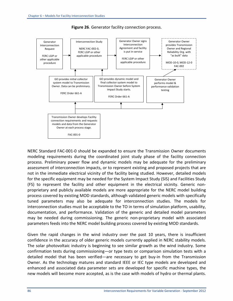
These standards were reviewed and reported in the NERC Special Report ldquoStandard Models for Variable Generationrdquo The ongoing detailed model validation may evolve to cover generator units or generator facilities 75 MVA or larger This breakpoint covers at least 80 percent of the currently installed generation in North America and matches the NERC Statement of Compliance Registry Criteria which is approved by FERC Generator facilities smaller than the 75 MVA thresholdmdashespecially variable generation facilitiesmdashmay experience rapid changes in control performance over their lifetimes due to equipment upgrades and replacements These changes should be captured in updated models However substantial modifications on facilities less than 75 MVA may not be captured by the FAC-001 standard or MOD standards It is recommended to modify FAC-001-0 to
ldquoR2 The Transmission Ownerrsquos facility connection requirements shall address but are not limited to the following items
Executive Summary
9 Interconnection Requirements for Variable Generation - September 2012
R211 Procedures for coordinated joint studies of new or substantially modified facilities4
and their impacts on the interconnected transmission systemsrdquo
NERC Standard FAC-001-0 Modifications Currently submittal of generator model data is covered via the following requirement in FAC-001-0
ldquoR2 The Transmission Ownerrsquos facility connection requirements shall address but are not limited to the following items R211 Procedures for coordinated joint studies of new facilities and their impacts on the interconnected transmission systemsrdquo
Transmission Owners make reference to the interconnection procedures in their respective Open Access Interconnection Tariff such as the FERC Large Generator Interconnection Procedures NERC Standard FAC-001-1 Facility Connection Requirements approved by the NERC Board of Trustees February 2012 addresses a number of issues related to FAC-001-0 including applying FAC-001-1 to Generator Owners as well as Transmission Owners as determined by NERCrsquos Registry Criteria
R3117 Generation facility modeling data including appropriate power flow short circuit and dynamic models and verification requirementsrdquo
Modeling needs for the interconnection process are different than modeling needs for evaluation of regional grid performance To clarify this point we recommend that the following statement be added to the FAC-001-0 standard as an appendix for clarifying R3117
ldquoPreliminary or approximate power flow and dynamic models may be adequate for the preliminary assessment of interconnection impacts or to represent existing and proposed projects that are not in the immediate electrical vicinity of the facility being studied However detailed dynamic (and possibly transient) models for the specific equipment may be needed for the System Impact Study and Facilities Study to represent the facility and other equipment in the electrical vicinity Generic non-proprietary publicly available models are more appropriate for the NERC model building process covered by existing MOD standards although validated generic models with specifically tuned parameters may be adequate for interconnection studies The models for interconnection studies must be acceptable to the Transmission Owner in terms of simulation platform usability documentation and performancerdquo
4 A generator modification is considered substantial if it results in a change in the net real power output by more than 10 of the original nameplate rating or more than 20 MW whichever is less or includes any of the following generator rewind rotor replacement new or refurbished excitation system or turbine replacement Replacement of failed equipment with identical spare units is not a substantial modification A substantially modified generator is a generator that receives Planning Coordinator agreement to make the generator modification after the effective date of this standard
Executive Summary
Interconnection Requirements for Variable Generation - September 2012 10
The above recommended sub-requirement R2117 as with all of the sub-requirements in FAC-001-0 leave it up to the Transmission Owner to ldquofill in the blanksrdquo or develop specific requirements that will be applied to facilities intending to interconnect to their network This can lead to inconsistencies across North America In order to avoid inconsistencies several Facility Interconnection requirement documents or grid codes were reviewed to try to develop a recommended best practice to aid Transmission Owners A review of grid codes as of 2011 can be found in Appendix 5 As mentioned previously the codes are in a constant state of evolution Summary of Facility Connection Model Grid Code Requirements After reviewing the interconnection procedures and standards of several grid codes with respect to models and model validation several key features could be recommended for adoption by Transmission Owners
bull Preliminary model data may be used for the initial feasibility study of a variable generator interconnection project
bull The best model available shall be used for the final System Impact Study or Facilities Study These models can be user-written and require nondisclosure agreements
bull The detailed dynamic model must be accurate over the frequency range of 01 to 5 Hz Time constants in the model should not be less than 5 ms
bull The detailed dynamics model must have been validated against a physical or type test
bull Verification of detailed model performance should be confirmed during commissioning to the extent possible The following tests shall be performed
primarysecondary voltage control
low-voltage and high-voltage ride-through
power factorreactive power capability
power ramping and power curtailment
bull Verification of the non-proprietary model accuracy may be performed by simulation tests compared with the detailed model performance
bull At the end of the commissioning tests the Generator Owner shall provide a verified detailed model and a non-proprietary model ideally in IEEE IEC or other approved format for ongoing Regional studies such as TPL-001
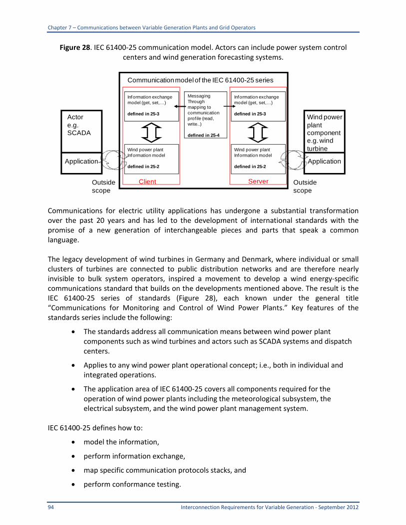
Communications between Variable Generation Plants and Grid Operators The project team recommends that the basic requirements for communications and control between grid operators and variable generation plants be based on existing policy for conventional generators
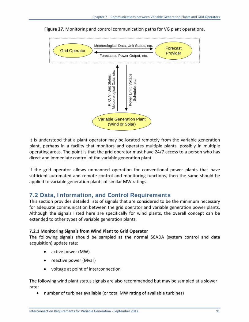
bull Variable generation plants should send a minimum set of monitoring data to the grid operation via the gridrsquos SCADA network (see Section 721)
Executive Summary
11 Interconnection Requirements for Variable Generation - September 2012
bull Variable generation plants should receive and execute command signals (power limit voltage schedule ramp rate limit etc) sent from the grid operator via the SCADA network (see Section 722)
bull Variable generation plants should have trained on-call plant operators that can receive calls from the grid operator 247 and immediately execute verbal commands The plant operators would not need to be located at the plant provided they have secure remote control capability for the plant
Chapter 1 ndash Introduction
Interconnection Requirements for Variable Generation - September 2012 12
1 Introduction 11 Background Existing state provincial and federal energy policies such as renewable portfolio standards (RPS) and production tax credits have driven development of wind plants in the United States and Canada that presently comprise in excess of 35 GW of installed capacity This trend is expected to continue with the addition of many other forms of renewable technologies such as photovoltaics (PV) Furthermore other technologies such as plug-in hybrid electric vehicles (PHEV) are also on the horizon Unlike traditional non-renewable resources the output of wind solar ocean and some hydro generation resources varies according to the availability of the primary fuel (wind sunlight and moving water) that cannot be reasonably stored Therefore these resources are considered variable following the availability of their primary fuel source There are two overarching attributes of a Variable Energy Resource (VER) that can impact the reliability of the bulk power system if not properly addressed
bull Variability The output of a VER changes according to the availability of the primary fuel resulting in fluctuations in the plant output on all time scales
bull Uncertainty The magnitude and timing of VER output is less predictable than for conventional generation
NERC is responsible for ensuring the reliability of the bulk power system in North America Anticipating the growth of VERs in December 2007 the NERC Planning and Operating Committees (PC and OC) created the Integration of Variable Generation Task Force (IVGTF) charging it with preparing a report [1] to identify the following
bull Technical considerations for integrating variable resources into the bulk power system and
bull Specific actions practices and requirements including enhancements to existing or development of new reliability standards
One of the identified follow-up tasks from Accommodating High Levels of Variable Generation was enhancement of generation plant interconnection requirements so they can be applied consistently to both conventional and variable generation resources For the purpose of completeness of this document the proposed action item Task 1-3 from is repeated below
Chapter 1 ndash Introduction
13 Interconnection Requirements for Variable Generation - September 2012
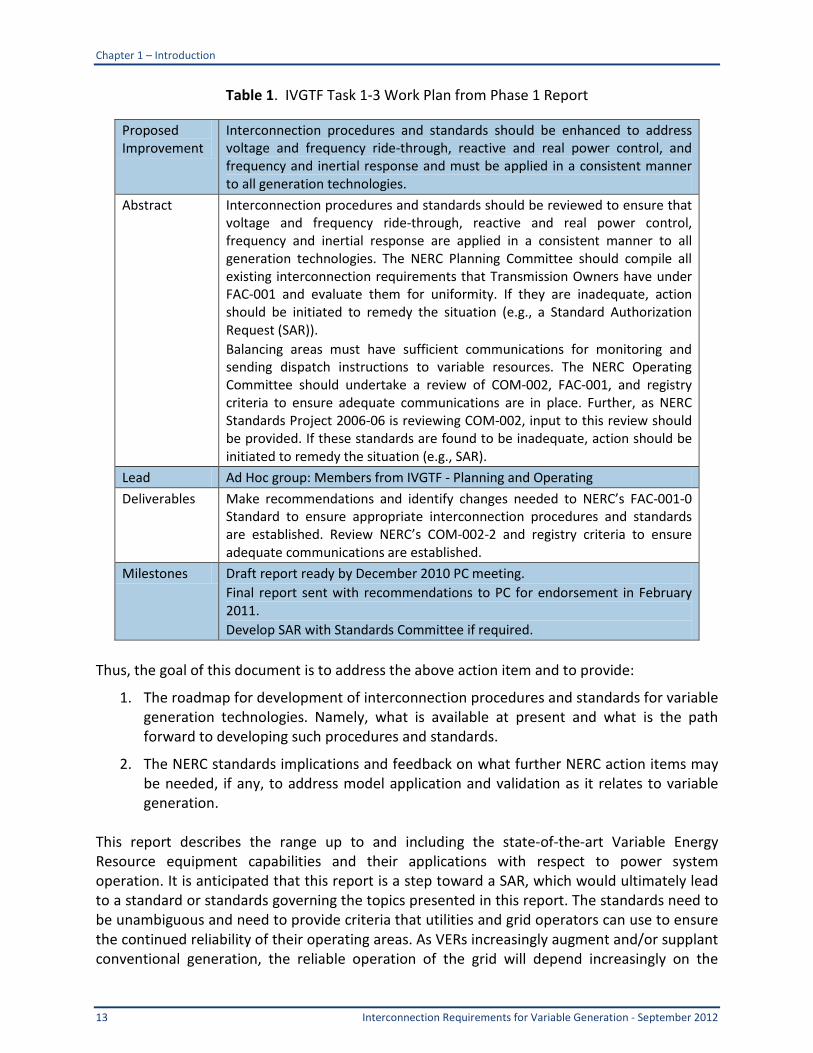
Table 1 IVGTF Task 1-3 Work Plan from Phase 1 Report
Proposed Improvement
Interconnection procedures and standards should be enhanced to address voltage and frequency ride-through reactive and real power control and frequency and inertial response and must be applied in a consistent manner to all generation technologies
Abstract Interconnection procedures and standards should be reviewed to ensure that voltage and frequency ride-through reactive and real power control frequency and inertial response are applied in a consistent manner to all generation technologies The NERC Planning Committee should compile all existing interconnection requirements that Transmission Owners have under FAC-001 and evaluate them for uniformity If they are inadequate action should be initiated to remedy the situation (eg a Standard Authorization Request (SAR)) Balancing areas must have sufficient communications for monitoring and sending dispatch instructions to variable resources The NERC Operating Committee should undertake a review of COM-002 FAC-001 and registry criteria to ensure adequate communications are in place Further as NERC Standards Project 2006-06 is reviewing COM-002 input to this review should be provided If these standards are found to be inadequate action should be initiated to remedy the situation (eg SAR)
Lead Ad Hoc group Members from IVGTF - Planning and Operating
Deliverables Make recommendations and identify changes needed to NERCrsquos FAC-001-0 Standard to ensure appropriate interconnection procedures and standards are established Review NERCrsquos COM-002-2 and registry criteria to ensure adequate communications are established
Milestones Draft report ready by December 2010 PC meeting Final report sent with recommendations to PC for endorsement in February 2011 Develop SAR with Standards Committee if required
Thus the goal of this document is to address the above action item and to provide
1 The roadmap for development of interconnection procedures and standards for variable generation technologies Namely what is available at present and what is the path forward to developing such procedures and standards
2 The NERC standards implications and feedback on what further NERC action items may be needed if any to address model application and validation as it relates to variable generation
This report describes the range up to and including the state-of-the-art Variable Energy Resource equipment capabilities and their applications with respect to power system operation It is anticipated that this report is a step toward a SAR which would ultimately lead to a standard or standards governing the topics presented in this report The standards need to be unambiguous and need to provide criteria that utilities and grid operators can use to ensure the continued reliability of their operating areas As VERs increasingly augment andor supplant conventional generation the reliable operation of the grid will depend increasingly on the
Chapter 1 ndash Introduction
Interconnection Requirements for Variable Generation - September 2012 14
reactive power control active power control and other contributions from VERs The new reliability standards should require that VERs adequately mimic or replace the capabilities that are lost when VERS supplant conventional generation 12 NERCrsquos Mission NERCrsquos mission is to ensure the reliability of the North American bulk power system NERC develops and enforces reliability standards assesses adequacy annually via a 10-year forecast and winter and summer forecasts monitors the bulk power system and educates trains and certifies industry personnel NERC is a self-regulatory organization subject to oversight by the US Federal Energy Regulatory Commission (FERC) and governmental authorities in Canada5
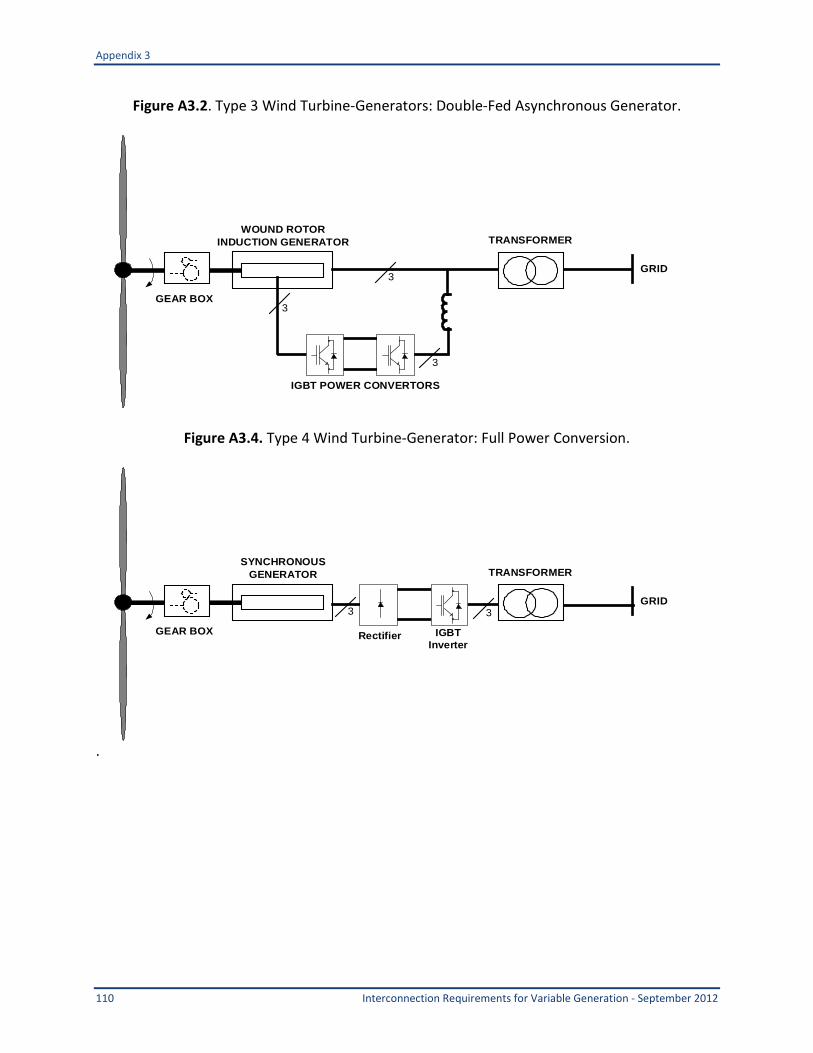
NERC assesses and reports on the reliability and adequacy of the North American bulk power system divided into the eight Regional Areas6 Figure 1 as shown in The users owners and operators of the bulk power system within these areas account for virtually all the electricity supplied in the United States Canada and a portion of Baja California Norte Mexico 13 Wind and Solar Generation Technologies Significant work has been published that defines the characteristics of variable generation Chapter 2 of the NERC Special Report ldquoAccommodating High Levels of Variable Generationrdquo summarized the characteristics of wind generation and solar generation including both solar thermal and solar photovoltaic and hydrokinetic generation Currently four main types of wind turbine technology have evolved These include fixed speed induction generators variable slip induction generators double-fed asynchronous generators and full power conversion generators (see Appendix D of this report) Solar generation falls into two major categories concentrating solar plants (CSP) and photovoltaic (PV) In a PV facility energy from photovoltaic panels is interconnected to the power grid through power electronic dc to ac converters CSP facilities capture solar energy as heat which generates steam to feed into a conventional steam turbine-generator Each type of wind or solar generation has varying capabilities in terms of the following
bull voltagevar controlregulation
bull voltage ride-through
bull power curtailment and ramping
bull primary frequency regulation
bull inertial response
5 As of June 18 2007 the US Federal Energy Regulatory Commission (FERC) granted NERC the legal authority to enforce reliability standards with all US users owners and operators of the bulk power system and made compliance with those standards mandatory and enforceable Reliability Standards are also mandatory and enforceable in Ontario and New Brunswick and NERC is seeking to achieve comparable results in the other Canadian provinces NERC will seek recognition in Mexico once necessary legislation is adopted 6 Note ERCOT and SPP are tasked with performing reliability self-assessments as they are Regional planning and operating organizations SPP-RE (SPP ndash Regional Entity) and TRE (Texas Regional Entity) are functional entities to whom NERC delegates certain compliance monitoring and enforcement authorities
Chapter 1 ndash Introduction
15 Interconnection Requirements for Variable Generation - September 2012
This report focuses primarily on wind generation and solar PV generation These forms of variable generation are being deployed at significant penetrations and are therefore creating reliability impacts on the BES Other forms of variable generation (eg hydrokinetic wave tidal) are still under development and are not expected to reach significant penetration levels in the near future Since CSP uses a steam turbine-generator as its interface to the power grid CSP facilities can use the same interconnection criteria as other conventional generation facilities with synchronous machines Hence CSP is not addressed in this report The present status of modeling variable generation is covered in chapter 3 of the NERC Special Report ldquoStandard Models for Variable Generationrdquo WECC IEEE and IEC are working toward the development of standard dynamic simulation models for wind turbine-generators WECC will also begin to develop generic models of solar PV arrays Many textbooks are now available in the subject area such as Wind Power in Power Systems by T Ackerman [2] and Integration of Alternative Sources of Energy by F Farret and M Godoy Simotildees [3] 14 Distribution Connected Variable Generation Given the growing penetration of distribution-connected variable generation there is an imminent potential for such generation resources to have a significant impact on the reliability of the bulk power system However these types of resources fall outside the jurisdiction of NERCrsquos Reliability Criteria and therefore no reliability-based interconnection requirements exist The reliability risks due to distribution-connected variable resources are being evaluated by IVGTF Task Force 1-8 (Potential Reliability Impacts of Distributed Resources) and Task Force 1-7 (Reconciling Existing LVRT and IEEE Requirements) Task Force 1-8 Potential Bulk System Reliability Impacts of Distributed Resources The goals of the Task Force 1-8 were to identify the potential adverse bulk system reliability impacts that are associated with high penetrations of emerging distributed resources and review the existing NERC Registry Criteria to ensure continued reliability in systems with large amounts of distributed energy resources The amount of distributed energy resources (DER) present in the electrical grid is forecast to grow in the next decade The IVGTF 1-8 report considers all types of DER including generation storage and demand response but many of the potential reliability impacts are driven by variable uncontrollable generation resources such as solar photovoltaic generation (PV) It is also recognized that many types of DER (demand response and storage for example) may improve bulk system reliability if managed properly In the past the distribution system was based mainly on distributing power from the transmission network and therefore its impact on bulk system reliability was relatively small As smart grid developments increase (resulting in more bi-directional flow of energy and provision of ancillary services from the distribution system) the impact on bulk system reliability needs to be understood and managed This report
Chapter 1 ndash Introduction
Interconnection Requirements for Variable Generation - September 2012 16
identifies the potential impacts these resources may have identifies potential mitigating strategies reviews the existing NERC Registry Criteria specific to DER applications and proposes potential future approaches to ensure continued reliability in systems with large amounts of DER These approaches include
bull Non-dispatchable rampingvariability of certain DER
bull Response to faults lack of low-voltage ride-through lack of frequency ride-through and coordination with the IEEE 1547 interconnection standards for distributed generation
bull Potential system protection considerations
bull Under-Frequency Load Shedding (UFLS) and Under-Voltage Load Shedding (UVLS) disconnecting generation and further reducing frequency and voltage support
bull Visibilitycontrollability of DER
bull Coordination of system restoration
bull Schedulingforecasting impacts on base loadcycling generation mix
bull Reactive power and voltage control
bull Impacts on forecast of apparent load seen by the transmission system
These issues may impact the bulk system at different levels of penetration depending on the characteristics of the particular area to which the distributed energy resources are connected Some factors will need to be managed by technical requirements (grid codes) for the distributed energy resources while others need the bulk system operator to adapt new planning or operational methods In North America the conflict between the transmission need for low-voltage ride-through and the IEEE 1547 standard (which mandates disconnection of distributed energy resources to allow distribution protection systems to operate and to prevent islanding) must be addressed The issue is separately considered in the Task Force 1ndash7 activities A fundamental component to mitigation will be the development or adjustment of standards While specific recommendations for guidelines or standards were not provided the following general recommendations were made by Task Force 1ndash8
bull NERC state regulators and industry should develop an analytical basis for understanding the potential magnitude of adverse reliability impacts and how that magnitude changes with penetration of DER and system configurationcomposition
bull Based in part on the analytical results from Accommodating High Levels of Variable Generation and the broad experience of generation transmission and distribution owners and operators specific recommendations for changes to operating and planning practices state programs and pertinent NERC Reliability Standards should be developed
bull As many DER issues may be beyond the scope of NERCrsquos authority and since it may be feasible to address these issues through non-NERC avenues (such as through market rules vertically integrated operations or state programs) it is recommended that NERC
Chapter 1 ndash Introduction
17 Interconnection Requirements for Variable Generation - September 2012
work with the affected entities in the different Regions including state agencies with jurisdiction over DER RTOs and vertically integrated utilities to develop appropriate guidelines practices and requirements to address issues impacting the reliability of the BES resulting from DER
The conclusions of these analyses will hopefully lead to new interconnection requirements for distribution-connected variable generators that would be consistent with the interconnection requirements for other high-penetration resources that have significant impact on overall grid reliability Task Force 1-7 Performance of Variable Resources During and After System Disturbances IVGTF Task Force 1-7 addressed Low-Voltage Ride-Through (LVRT) requirements for VERs interconnected on the electrical power system at BES and distribution facilities The task force prepared a report summarizing potential reliability impacts if the VERs did not remain interconnected stable and functional during and after normally expected system disturbances The report also addresses inconsistent and conflicting existing requirements for BES-connected and distribution system-connected VERs and provides recommendations for changes needed in the LVRT requirements to preserve the expected levels of power system reliability IVGTF task 1-7 report also discusses requirements for VERs to be able to remain interconnected stable and functioning during and after frequency disturbances similar to those resulting from sudden loss of generation or load One of the challenges for the LVRT requirements is that the BES-connected VERs are under FERC jurisdiction and FERC and NERC standards are applicable that address their performance requirements eg FERC Order 661-A for LVRT requirements for wind generation and NERC standards TPL-002 and PRC-019 On the other hand distribution system-connected VERs in most cases are under state utility commission jurisdictions and in most cases their performance requirements are dictated by IEEE Standard 1547 IVGTF Task Force 1-7 did not address reactive requirements of VERs for voltage control or voltage regulation though task force members strongly feel they are essential and can have significant contribution in normal operation as well as reliability of the system IVGTF Task 1-7 also did not address reactive injections during system faults (This report completed by IVGTF Task 1-3 group addresses voltage control and reactive power requirements)
Chapter 1 ndash Introduction
Interconnection Requirements for Variable Generation - September 2012 18
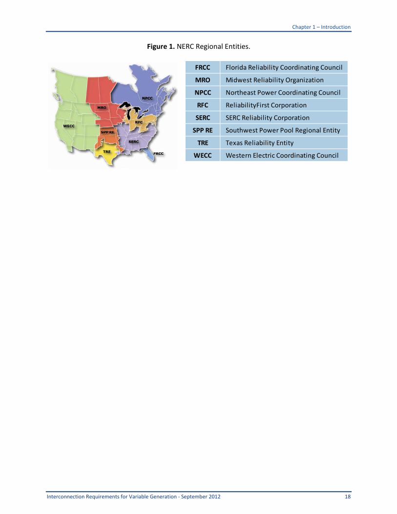
Figure 1 NERC Regional Entities
FRCC Florida Reliability Coordinating Council
MRO Midwest Reliability Organization
NPCC Northeast Power Coordinating Council
RFC ReliabilityFirst Corporation
SERC SERC Reliability Corporation
SPP RE Southwest Power Pool Regional Entity
TRE Texas Reliability Entity
WECC Western Electric Coordinating Council
Chapter 2 ndash Reactive Power and Voltage
19 Interconnection Requirements for Variable Generation - September 2012
2 Reactive Power and Voltage 21 Background Voltage on the North American bulk system is normally regulated by Generator Operators which typically are provided with voltage schedules by Transmission Operators In the past variable generation plants were considered very small relative to conventional generating units and were characteristically either induction generator (wind) or line-commutated inverters (PV) that had no inherent voltage regulation capability Bulk system voltage regulation was provided almost exclusively by synchronous generators However the growing level of penetration of non-traditional renewable generationmdashespecially wind and solarmdashhas led to the need for renewable generation to contribute more significantly to power system voltage and reactive regulation For the most part new wind plants use doubly fed asynchronous generators or full-conversion machines with self-commutated electronic interfaces that have considerable dynamic reactive and voltage regulation capability If needed to meet interconnection requirements the reactive power capability of solar and wind plants can be further enhanced by adding SVC STATCOMS and other reactive support equipment at the plant level It should be noted that converters need to be sized larger to provide reactive power capability at full output Currently inverter-based reactive capability is more costly compared to the same capability supplied by synchronous machines Partly for this reason FERC stipulated in Order 661-A (applicable to wind generators) that a site-specific study must be conducted by the transmission operator to justify the reactive capability requirement up to 095 lag to lead at the point of interconnection For solar PV it is expected that similar interconnection requirements for power factor range and low-voltage ride-through will be formulated in the near future Inverters used for solar PV and wind plants can provide reactive capability at partial output but any inverter-based reactive capability at full power implies that the converter needs to be sized larger to handle full active and reactive current Nonetheless variable generation resources such as wind and solar PV are often located in remote locations with weak transmission connections It is not uncommon for wind plants and solar PV sites to have short circuit ratios (ie ratios of three-phase short circuit MVA divided by nominal MVA rating of the plant) of 5 or less Voltage support in systems like this is a vital ancillary service to prevent voltage instability and ensure good power transfer Voltage regulation in distribution systems is normally performed at the distribution substation level and distribution voltage regulation by distributed resources is not allowed by IEEE 1547 Normally distributed resources operate with fixed power factor with respect to the local system 22 Reactive Capability of Synchronous Generators Customarily when reactive capability of variable generation resources is specified for transmission interconnections it is done at the Point of Interconnection (POI) which is the point at which power is delivered to the transmission system This is often (but not always) at
Chapter 2 ndash Reactive Power and Voltage
Interconnection Requirements for Variable Generation - September 2012 20
the high side of the main facility transformer A typical requirement would be 095 lag to lead power factor7
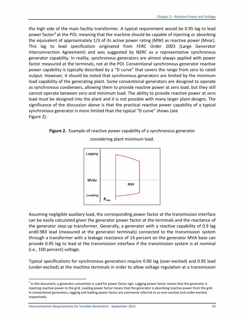
at the POI meaning that the machine should be capable of injecting or absorbing the equivalent of approximately 13 of its active power rating (MW) as reactive power (Mvar) This lag to lead specification originated from FERC Order 2003 (Large Generator Interconnection Agreement) and was suggested by NERC as a representative synchronous generator capability In reality synchronous generators are almost always applied with power factor measured at the terminals not at the POI Conventional synchronous generator reactive power capability is typically described by a ldquoD curverdquo that covers the range from zero to rated output However it should be noted that synchronous generators are limited by the minimum load capability of the generating plant Some conventional generators are designed to operate as synchronous condensers allowing them to provide reactive power at zero load but they still cannot operate between zero and minimum load The ability to provide reactive power at zero load must be designed into the plant and it is not possible with many larger plant designs The significance of the discussion above is that the practical reactive power capability of a typical synchronous generator is more limited than the typical ldquoD curverdquo shows (see Figure 2)
Figure 2 Example of reactive power capability of a synchronous generator
considering plant minimum load
Assuming negligible auxiliary load the corresponding power factor at the transmission interface can be easily calculated given the generator power factor at the terminals and the reactance of the generator step-up transformer Generally a generator with a reactive capability of 09 lag and0983 lead (measured at the generator terminals) connected to the transmission system through a transformer with a leakage reactance of 14 percent on the generator MVA base can provide 095 lag to lead at the transmission interface if the transmission system is at nominal (ie 100 percent) voltage Typical specifications for synchronous generators require 090 lag (over-excited) and 095 lead (under-excited) at the machine terminals in order to allow voltage regulation at a transmission
7 In this document a generator convention is used for power factor sign Lagging power factor means that the generator is injecting reactive power to the grid Leading power factor means that the generator is absorbing reactive power from the grid In conventional generators lagging and leading power factor are commonly referred to as over-excited and under-excited respectively
Pmin
Chapter 2 ndash Reactive Power and Voltage
21 Interconnection Requirements for Variable Generation - September 2012
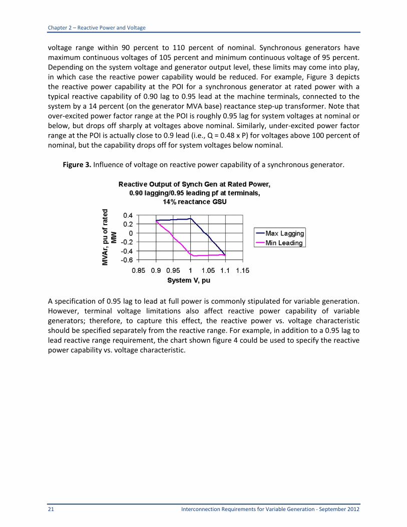
voltage range within 90 percent to 110 percent of nominal Synchronous generators have maximum continuous voltages of 105 percent and minimum continuous voltage of 95 percent Depending on the system voltage and generator output level these limits may come into play in which case the reactive power capability would be reduced For example Figure 3 depicts the reactive power capability at the POI for a synchronous generator at rated power with a typical reactive capability of 090 lag to 095 lead at the machine terminals connected to the system by a 14 percent (on the generator MVA base) reactance step-up transformer Note that over-excited power factor range at the POI is roughly 095 lag for system voltages at nominal or below but drops off sharply at voltages above nominal Similarly under-excited power factor range at the POI is actually close to 09 lead (ie Q = 048 x P) for voltages above 100 percent of nominal but the capability drops off for system voltages below nominal
Figure 3 Influence of voltage on reactive power capability of a synchronous generator
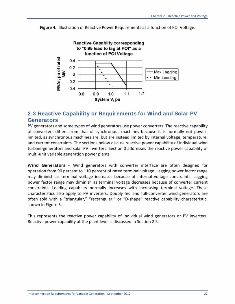
A specification of 095 lag to lead at full power is commonly stipulated for variable generation However terminal voltage limitations also affect reactive power capability of variable generators therefore to capture this effect the reactive power vs voltage characteristic should be specified separately from the reactive range For example in addition to a 095 lag to lead reactive range requirement the chart shown figure 4 could be used to specify the reactive power capability vs voltage characteristic
Chapter 2 ndash Reactive Power and Voltage
Interconnection Requirements for Variable Generation - September 2012 22
Figure 4 Illustration of Reactive Power Requirements as a function of POI Voltage
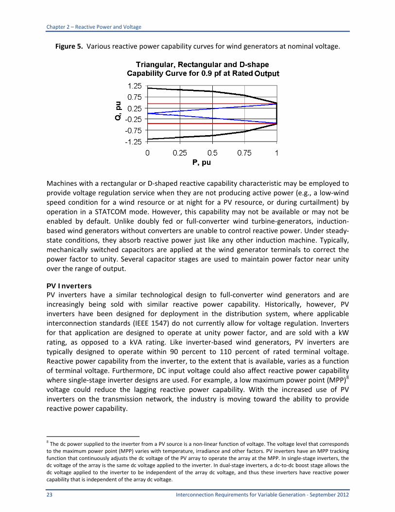
23 Reactive Capability or Requirements for Wind and Solar PV Generators PV generators and some types of wind generators use power converters The reactive capability of converters differs from that of synchronous machines because it is normally not power-limited as synchronous machines are but are instead limited by internal voltage temperature and current constraints The sections below discuss reactive power capability of individual wind turbine-generators and solar PV inverters Section 0 addresses the reactive power capability of multi-unit variable generation power plants Wind Generators - Wind generators with converter interface are often designed for operation from 90 percent to 110 percent of rated terminal voltage Lagging power factor range may diminish as terminal voltage increases because of internal voltage constraints Lagging power factor range may diminish as terminal voltage decreases because of converter current constraints Leading capability normally increases with increasing terminal voltage These characteristics also apply to PV inverters Doubly fed and full-converter wind generators are often sold with a ldquotriangularrdquo ldquorectangularrdquo or ldquoD-shaperdquo reactive capability characteristic shown in Figure 5 This represents the reactive power capability of individual wind generators or PV inverters Reactive power capability at the plant level is discussed in Section 25
Chapter 2 ndash Reactive Power and Voltage
23 Interconnection Requirements for Variable Generation - September 2012
Figure 5 Various reactive power capability curves for wind generators at nominal voltage
Machines with a rectangular or D-shaped reactive capability characteristic may be employed to provide voltage regulation service when they are not producing active power (eg a low-wind speed condition for a wind resource or at night for a PV resource or during curtailment) by operation in a STATCOM mode However this capability may not be available or may not be enabled by default Unlike doubly fed or full-converter wind turbine-generators induction-based wind generators without converters are unable to control reactive power Under steady-state conditions they absorb reactive power just like any other induction machine Typically mechanically switched capacitors are applied at the wind generator terminals to correct the power factor to unity Several capacitor stages are used to maintain power factor near unity over the range of output PV Inverters PV inverters have a similar technological design to full-converter wind generators and are increasingly being sold with similar reactive power capability Historically however PV inverters have been designed for deployment in the distribution system where applicable interconnection standards (IEEE 1547) do not currently allow for voltage regulation Inverters for that application are designed to operate at unity power factor and are sold with a kW rating as opposed to a kVA rating Like inverter-based wind generators PV inverters are typically designed to operate within 90 percent to 110 percent of rated terminal voltage Reactive power capability from the inverter to the extent that is available varies as a function of terminal voltage Furthermore DC input voltage could also affect reactive power capability where single-stage inverter designs are used For example a low maximum power point (MPP)8
voltage could reduce the lagging reactive power capability With the increased use of PV inverters on the transmission network the industry is moving toward the ability to provide reactive power capability
8 The dc power supplied to the inverter from a PV source is a non-linear function of voltage The voltage level that corresponds to the maximum power point (MPP) varies with temperature irradiance and other factors PV inverters have an MPP tracking function that continuously adjusts the dc voltage of the PV array to operate the array at the MPP In single-stage inverters the dc voltage of the array is the same dc voltage applied to the inverter In dual-stage inverters a dc-to-dc boost stage allows the dc voltage applied to the inverter to be independent of the array dc voltage and thus these inverters have reactive power capability that is independent of the array dc voltage
Chapter 2 ndash Reactive Power and Voltage
Interconnection Requirements for Variable Generation - September 2012 24
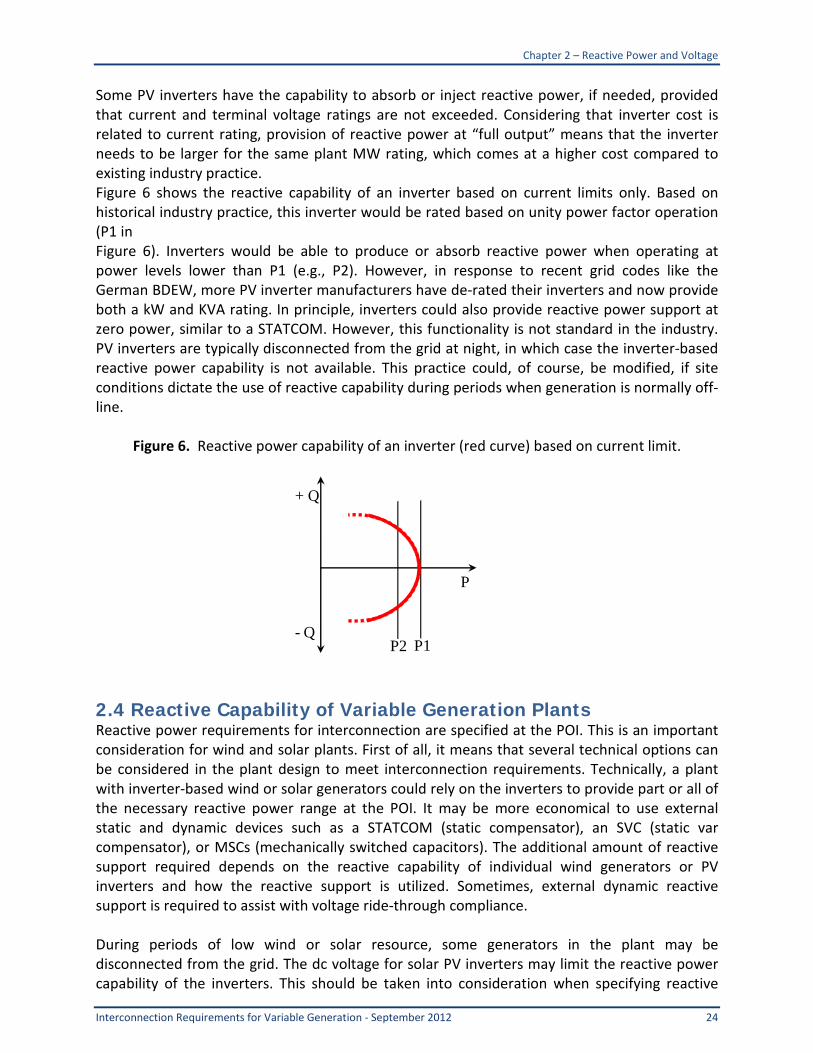
Some PV inverters have the capability to absorb or inject reactive power if needed provided that current and terminal voltage ratings are not exceeded Considering that inverter cost is related to current rating provision of reactive power at ldquofull outputrdquo means that the inverter needs to be larger for the same plant MW rating which comes at a higher cost compared to existing industry practice Figure 6 shows the reactive capability of an inverter based on current limits only Based on historical industry practice this inverter would be rated based on unity power factor operation (P1 in Figure 6) Inverters would be able to produce or absorb reactive power when operating at power levels lower than P1 (eg P2) However in response to recent grid codes like the German BDEW more PV inverter manufacturers have de-rated their inverters and now provide both a kW and KVA rating In principle inverters could also provide reactive power support at zero power similar to a STATCOM However this functionality is not standard in the industry PV inverters are typically disconnected from the grid at night in which case the inverter-based reactive power capability is not available This practice could of course be modified if site conditions dictate the use of reactive capability during periods when generation is normally off-line
Figure 6 Reactive power capability of an inverter (red curve) based on current limit
24 Reactive Capability of Variable Generation Plants Reactive power requirements for interconnection are specified at the POI This is an important consideration for wind and solar plants First of all it means that several technical options can be considered in the plant design to meet interconnection requirements Technically a plant with inverter-based wind or solar generators could rely on the inverters to provide part or all of the necessary reactive power range at the POI It may be more economical to use external static and dynamic devices such as a STATCOM (static compensator) an SVC (static var compensator) or MSCs (mechanically switched capacitors) The additional amount of reactive support required depends on the reactive capability of individual wind generators or PV inverters and how the reactive support is utilized Sometimes external dynamic reactive support is required to assist with voltage ride-through compliance During periods of low wind or solar resource some generators in the plant may be disconnected from the grid The dc voltage for solar PV inverters may limit the reactive power capability of the inverters This should be taken into consideration when specifying reactive
+ Q
P
- Q P1 P2
Chapter 2 ndash Reactive Power and Voltage
25 Interconnection Requirements for Variable Generation - September 2012
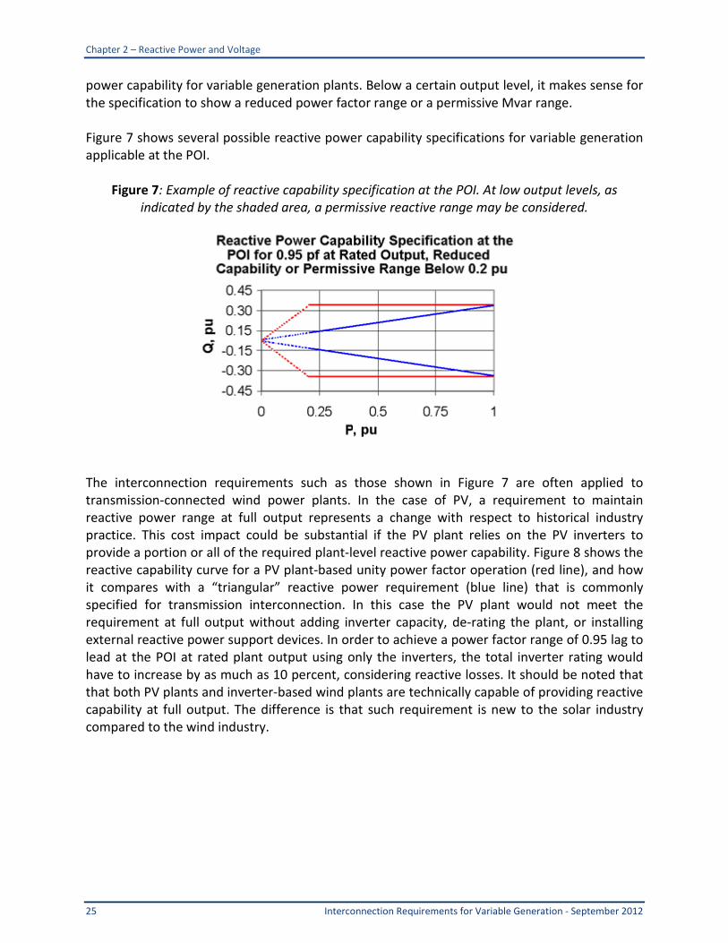
power capability for variable generation plants Below a certain output level it makes sense for the specification to show a reduced power factor range or a permissive Mvar range Figure 7 shows several possible reactive power capability specifications for variable generation applicable at the POI
Figure 7 Example of reactive capability specification at the POI At low output levels as indicated by the shaded area a permissive reactive range may be considered
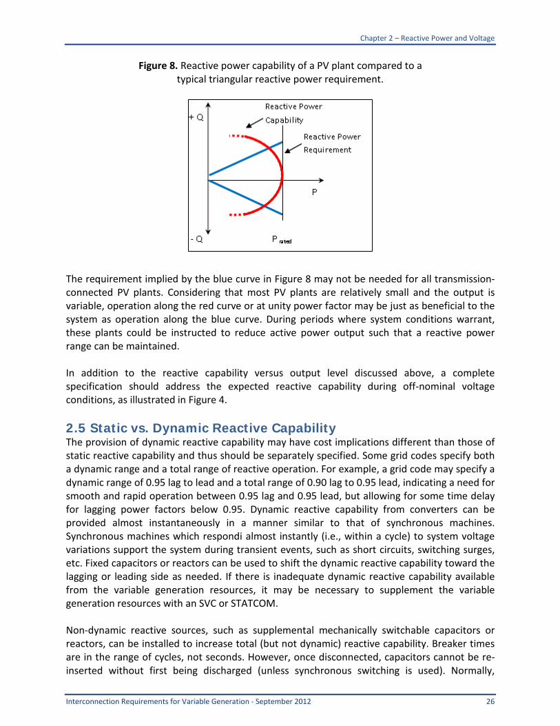
The interconnection requirements such as those shown in Figure 7 are often applied to transmission-connected wind power plants In the case of PV a requirement to maintain reactive power range at full output represents a change with respect to historical industry practice This cost impact could be substantial if the PV plant relies on the PV inverters to provide a portion or all of the required plant-level reactive power capability Figure 8 shows the reactive capability curve for a PV plant-based unity power factor operation (red line) and how it compares with a ldquotriangularrdquo reactive power requirement (blue line) that is commonly specified for transmission interconnection In this case the PV plant would not meet the requirement at full output without adding inverter capacity de-rating the plant or installing external reactive power support devices In order to achieve a power factor range of 095 lag to lead at the POI at rated plant output using only the inverters the total inverter rating would have to increase by as much as 10 percent considering reactive losses It should be noted that that both PV plants and inverter-based wind plants are technically capable of providing reactive capability at full output The difference is that such requirement is new to the solar industry compared to the wind industry
Chapter 2 ndash Reactive Power and Voltage
Interconnection Requirements for Variable Generation - September 2012 26
Figure 8 Reactive power capability of a PV plant compared to a typical triangular reactive power requirement
The requirement implied by the blue curve in Figure 8 may not be needed for all transmission-connected PV plants Considering that most PV plants are relatively small and the output is variable operation along the red curve or at unity power factor may be just as beneficial to the system as operation along the blue curve During periods where system conditions warrant these plants could be instructed to reduce active power output such that a reactive power range can be maintained In addition to the reactive capability versus output level discussed above a complete specification should address the expected reactive capability during off-nominal voltage conditions as illustrated in Figure 4
25 Static vs Dynamic Reactive Capability The provision of dynamic reactive capability may have cost implications different than those of static reactive capability and thus should be separately specified Some grid codes specify both a dynamic range and a total range of reactive operation For example a grid code may specify a dynamic range of 095 lag to lead and a total range of 090 lag to 095 lead indicating a need for smooth and rapid operation between 095 lag and 095 lead but allowing for some time delay for lagging power factors below 095 Dynamic reactive capability from converters can be provided almost instantaneously in a manner similar to that of synchronous machines Synchronous machines which respondi almost instantly (ie within a cycle) to system voltage variations support the system during transient events such as short circuits switching surges etc Fixed capacitors or reactors can be used to shift the dynamic reactive capability toward the lagging or leading side as needed If there is inadequate dynamic reactive capability available from the variable generation resources it may be necessary to supplement the variable generation resources with an SVC or STATCOM Non-dynamic reactive sources such as supplemental mechanically switchable capacitors or reactors can be installed to increase total (but not dynamic) reactive capability Breaker times are in the range of cycles not seconds However once disconnected capacitors cannot be re-inserted without first being discharged (unless synchronous switching is used) Normally
Chapter 2 ndash Reactive Power and Voltage
27 Interconnection Requirements for Variable Generation - September 2012
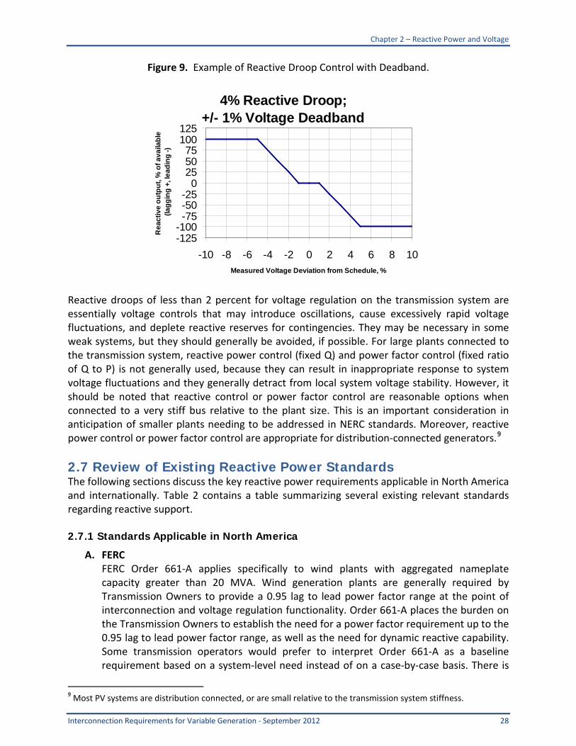
discharge takes five minutes Rapid discharge transformers can be applied to execute discharge in a few seconds Good engineering practice requires that consideration be given to operation of switched reactive resources For example it is sometimes required that lagging reactive capability be placed in service as a function of variable generation output irrespective of system voltage conditions A Transmission Operator may require for example that capacitors be placed in service to compensate for transmission reactive losses whenever the output of a wind plant exceeds 90 percent of rated capability If the system voltage is high and the turbines are already operating at the leading power factor limit placing capacitors in service may cause a high transient and steady-state overvoltage that can result in turbine tripping and other operational difficulties It may be necessary to adjust transformer taps to bias turbine voltages in a safe direction if such operation is necessary Operational Considerations Reactive capability on transmission systems is typically deployed in voltage regulation mode The transmission operator provides a voltage schedule and the generator (conventional or variable generation) is expected to adjust reactive output to keep the voltage close to the set point level Normally this is done by regulating the resourcersquos terminal voltage on the low side of the resourcersquos main transformer Another emerging practice is to adjust reactive output based on a ldquoreactive drooprdquo characteristic using the transmission voltage Reactive droop in the range of 2 percent to 10 percent is typically employed A typical drop of 4 percent simply means that the resource will adjust reactive output linearly with deviation from scheduled voltage so that full reactive capability is deployed when the measured voltage deviates from the scheduled voltage by more than 4 percent A 1 percent deviation results in 25 percent of available reactive capability being deployed A voltage deviation less than the deadband limit would not require the resource to change reactive power output Figure 9 shows an example of a reactive droop control with deadband The specifications of the reactive droop requirement (eg the deadband of the droop response together with the response time to voltage changes) may lead to requirements for dynamic reactive power support as well as potentially fast-acting plant controller behavior Reactive droop capability is an emerging capability for solar PV plants although there are no technical impediments to the implementation of such control schemes Individual wind generators and solar PV inverters typically follow a power factor or reactive power set point The power factor set point can be adjusted by a plant-level voltvar regulator thus allowing the generators to participate in voltage control In some cases the relatively slow communication interface (on the order of several seconds) of inverters limits the reactive power response time
Chapter 2 ndash Reactive Power and Voltage
Interconnection Requirements for Variable Generation - September 2012 28
Figure 9 Example of Reactive Droop Control with Deadband
Reactive droops of less than 2 percent for voltage regulation on the transmission system are essentially voltage controls that may introduce oscillations cause excessively rapid voltage fluctuations and deplete reactive reserves for contingencies They may be necessary in some weak systems but they should generally be avoided if possible For large plants connected to the transmission system reactive power control (fixed Q) and power factor control (fixed ratio of Q to P) is not generally used because they can result in inappropriate response to system voltage fluctuations and they generally detract from local system voltage stability However it should be noted that reactive control or power factor control are reasonable options when connected to a very stiff bus relative to the plant size This is an important consideration in anticipation of smaller plants needing to be addressed in NERC standards Moreover reactive power control or power factor control are appropriate for distribution-connected generators9
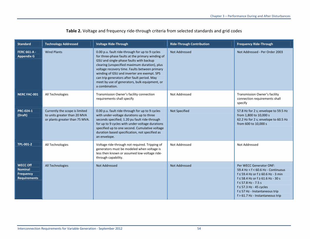
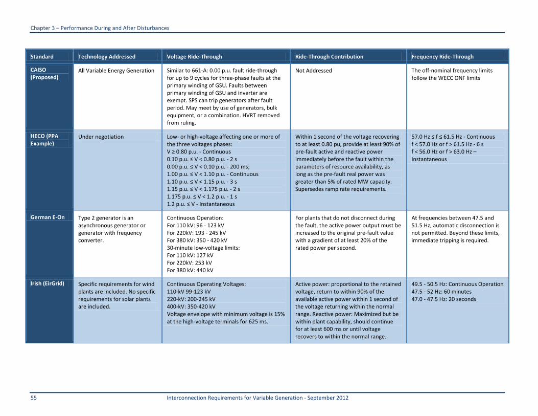
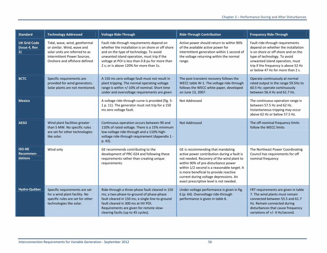
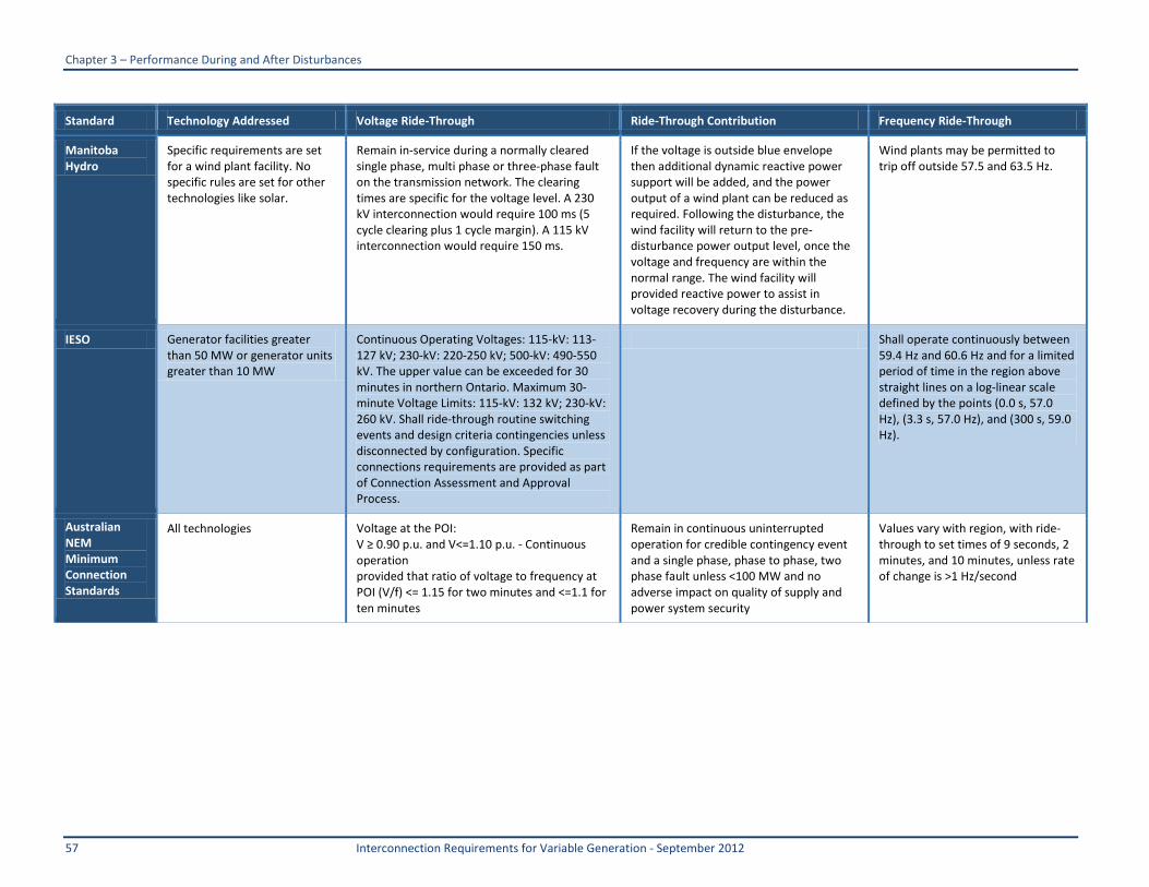
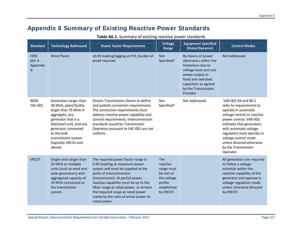
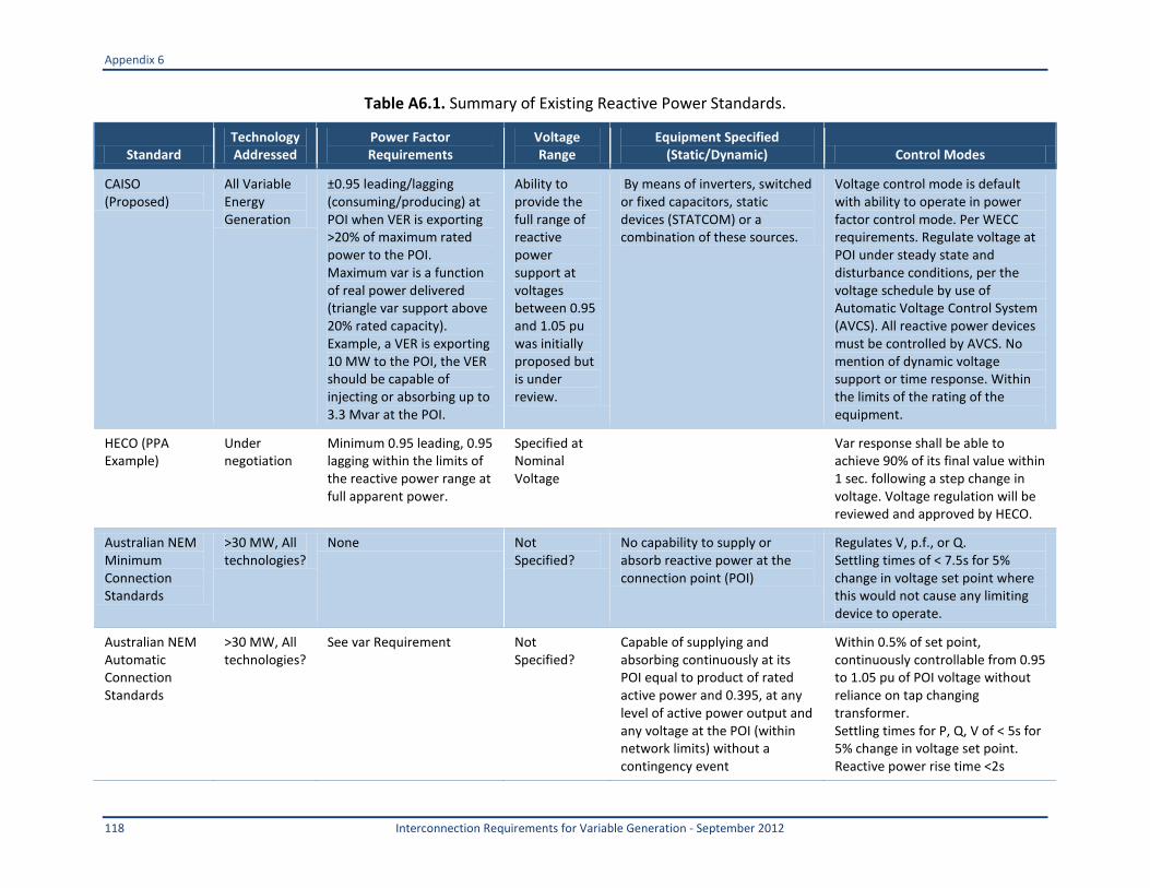
27 Review of Existing Reactive Power Standards The following sections discuss the key reactive power requirements applicable in North America and internationally Table 2 contains a table summarizing several existing relevant standards regarding reactive support 271 Standards Applicable in North America
A FERC FERC Order 661-A applies specifically to wind plants with aggregated nameplate capacity greater than 20 MVA Wind generation plants are generally required by Transmission Owners to provide a 095 lag to lead power factor range at the point of interconnection and voltage regulation functionality Order 661-A places the burden on the Transmission Owners to establish the need for a power factor requirement up to the 095 lag to lead power factor range as well as the need for dynamic reactive capability Some transmission operators would prefer to interpret Order 661-A as a baseline requirement based on a system-level need instead of on a case-by-case basis There is
9 Most PV systems are distribution connected or are small relative to the transmission system stiffness
4 Reactive Droop +- 1 Voltage Deadband
-125-100-75-50-25
0255075
100125
-10 -8 -6 -4 -2 0 2 4 6 8 10Measured Voltage Deviation from Schedule
Rea
ctiv
e ou
tput
o
f ava
ilabl
e (l
aggi
ng +
lea
ding
-)
Chapter 2 ndash Reactive Power and Voltage
29 Interconnection Requirements for Variable Generation - September 2012
still a great deal of uncertainty regarding this issue for all types of variable generation Furthermore there are different interpretations and a lack of clarity regarding the amount of dynamic versus static reactive power that is required with Order 661-A requiring that wind plants provide sufficient dynamic voltage support in lieu of PSS and AVR FERCrsquos interconnection requirements currently do not contain language that applies to solar generation However generation interconnection procedures in California were recently revised to incorporate provisions similar to FERC Order 661-A but applicable to all asynchronous generatorsmdashsee discussion in Section D below
B NERC Applicability of NERC standards to generators is defined in the current NERC Statement of Compliance Registry Criteria Generators larger than 20 MVA plantfacility larger than 75 MVA in aggregate and any generator that is a blackstart unit is subject to NERC standards Regional standards and other requirements supplement the NERC standards An important consideration is that NERC standards unlike some Regional grid codes strive to be technology neutral A good example of this philosophy is the PRC-024 standard on voltage and frequency tolerance which is currently being drafted
FAC-001 directs the Transmission Owner to define and publish connection requirements for facilities including generators The connection requirements must address reactive power capability and control requirements (R313 and R319) As stated in the previous section the manner in which reactive power capability may be used affects interconnection requirements In that regard NERC VAR standards address operating requirements with respect to reactive power control although the language used is more pertinent to synchronous generation and could be modified to better address variable generation VAR-001 R3 states ldquoThe Transmission Operator shall specify criteria that exempt generators from compliance with the requirements defined in Requirement 4 and Requirement 61rdquo VAR-001 R4 and R61 refer to requirements to operate in automatic voltage control or reactive power control VAR-002 indicates that generators with automatic voltage regulators must operate in voltage control mode unless directed otherwise by the Transmission Operator
Interconnection standards issued by Transmission Operators pursuant to FAC-001 are not uniform Some Transmission Operators address the reactive power requirements explicitly and some just refer back to the FERC pro-forma LGIASGIA For example the Idaho Power document states in Section R219 ldquoIPCrsquos voltage reactive power and power factor control requirements for generators are described in its generator interconnection agreements The requirements for generators larger than 20 MW are listed in section 96 of IPCrsquos Standard Large Generator Interconnection Agreement (LGIA) For generators smaller than 20 MW Section 18 of IPCrsquos Small Generator Interconnection Agreement (SGIA) describes the requirementsrdquo
In contrast the PGampE Generation Interconnection Handbook states in Section G3122 ldquoWind generating facilities must provide unity power factor at the point of interconnection (POI) unless PGampE studies specify a range PGampE may further require the provision of reactive support equivalent to that provided by operating a synchronous generator anywhere within the range from 95 percent leading power factor (absorbing vars) to 90 percent lagging power factor (producing vars) within an
Chapter 2 ndash Reactive Power and Voltage
Interconnection Requirements for Variable Generation - September 2012 30
operating range of plusmn5 percent of rated generator terminal voltage and full load (This is typical if the induction project is greater than 1000 kW)rdquo
Further in G313 the PGampE document states ldquoInverter-based generating facilities need to provide reactive power (vars) to control voltage It shall be measured at the facility side (generally the low-voltage side) of the step-up transformer that connects to PGampE The facility reactive capability shall be at least capable of providing 43 percent of facility watt rating into the system and capable of accepting 31 percent of facility watt rating from the systemrdquo Other standards related to reactive power capability are reviewed below
C ERCOT ERCOT Generator Interconnection or Change Request Procedures10
D California ISO
apply to single units larger than 20 MVA or multiple units (such as wind and solar generators) with aggregated capacity of 20 MVA connected to the transmission system The required power factor range is 095 lag to lead at maximum power output and must be supplied at the point of interconnection (transmission) At partial power reactive capability must be up to the Mvar range at rated power or at least the required range at rated power scaled by the ratio of active power to rated power The reactive range must be met at the voltage profile established by ERCOT All generators are required to follow a voltage schedule within the reactive capability of the generator and operate in voltage regulation mode unless otherwise directed by ERCOT at power output levels equal to or greater than 10 percent of rated output
The California ISO recently proposed more detailed power factor requirements that apply to all forms of ldquoasynchronous generationrdquo (including wind and solar) The proposed requirement was a 095 lag to lead power factor baseline requirement at the POI A parallelogram similar to the one in Figure 3 was used to specify reactive power capability versus voltage The proposed standard also would have allowed a permissive reactive range when the generating facility output is below 20 percent of rated active power output It also stated that the reactive power must be met at full real power output and clarified that the reactive power capabilities could be met with external static or dynamic reactive power support equipment Specific requirement for automatic voltage regulation included definitions for voltage deadband and response time FERC rejected the CAISO proposal on the grounds that baseline reactive power requirements should be justified by a specific interconnection study
E HECO The Hawaiian Electric Company (HECO) currently is determining the power factor requirements through the interconnection agreement and PPA process including for sites below 20 MW The requirements are similar to those proposed by other bodies with indications that a var requirement (that corresponds to 095 power factor at rated power) would be satisfactory in place of a power factor requirement
10 httpwwwercotcomgridinfogenerationERCOTGenIntChngRequestProcedure09122007doc
Chapter 2 ndash Reactive Power and Voltage
31 Interconnection Requirements for Variable Generation - September 2012
F AESO The Alberta Electric System Operator (AESO) specifies reactive power requirements for wind generators as shown in Figure 7 The basic requirement is that sustained reactive power capability shall meet or exceed 09 lag to 095 lead power factor based on the aggregated plant MW level A portion of the reactive capability 095 lag to 0985 lead must be dynamic Short-term reactive power capability that can be sustained for one second or longer counts toward the required dynamic reactive power capability Subject to review and approval of the AESO several wind plants connected to a common transmission substation may consider aggregating voltage regulation and reactive power from a single source to meet the overall reactive power requirement The intent of voltage regulation requirements is to achieve reasonable response to disturbances as well as a steady-state regulation of +- 05 percent of the controlled voltage The standard identifies a minimum requirement for dynamic reactive power and permits some controlled reactive devices such as capacitor banks to satisfy total reactive power requirements The reactive power performance (as shown in Figure 10) and voltage regulation is assessed at the low-voltage side of the transmission step-up transformers and at rated collector system voltage
Chapter 2 ndash Reactive Power and Voltage
Interconnection Requirements for Variable Generation - September 2012 32
Figure 10 Reactive Power Capability Requirement for AESO
G Reactive Power Requirements Applicable to Distribution Interconnection In North America distribution interconnections generally conform to IEEE 1547 standards as codified in FERCrsquos Standard Generator Procedures (SGIP) (although interconnections at distribution are generally not FERC jurisdictional) and state and provincial-level interconnection procedures With respect to reactive power IEEE 15471 states that output power factor must be 085 lag to lead or higher however distribution-connected PV and wind systems are typically designed to operate at unity or leading power factor under power factor control and can provide little or no reactive capability at full output Operating in voltage control often required for transmission-connected generation is not permitted under IEEE 1547
Chapter 2 ndash Reactive Power and Voltage
33 Interconnection Requirements for Variable Generation - September 2012
272 International Standards There are several good examples of interconnection standards that apply to interconnection of variable generation in Europe and elsewhere Some examples are provided below
A Wind Generation ldquoGrid Codesrdquo in Europe In Europe interconnection standards for wind generationmdashknown as ldquogrid codesrdquomdashare relatively mature compared to standards in North America Standards vary across transmission operator jurisdictions and there are efforts underway to harmonize the format of the standards Power factor design requirements are expressed as a Q vs P capability curve Some examples are provided in Figure 11 These charts specify reactive power requirements across the full operating range of active powermdashnot only at full output As a point of reference power factor design requirements at full output vary between unity and 09 underover excited at the point of connection Most codes recognize that reactive power capability depends on voltage conditions and contain specifications to that effect
Chapter 2 ndash Reactive Power and Voltage
Interconnection Requirements for Variable Generation - September 2012 34
Figure 11 Sample reactive capability PQ charts from different TOs in Europe
Some grid codes specify the portion of the capability curve that must be dynamic similar to the AESO standard (Alberta) Some grid codes discuss how this reactive capability may be utilized in operations (voltagedroop control power factor control and reactive power control) and the expected response times for each Some grid codes also discuss the control strategy required during fault conditions which could play a role in the system design and equipment selection
B Medium Voltage Standards in Germany Interconnection requirements for solar PV systems installed at medium voltage (10 kV to 100 kV) were recently put into effect in Germany The power factor design criterion is 095
Chapter 2 ndash Reactive Power and Voltage
35 Interconnection Requirements for Variable Generation - September 2012
lag to lead at full output which requires inverters to be oversized or de-rated This standard also requires dynamic reactive power support during voltage excursions
28 Specific Recommendations to Improve Interconnection Standards 281 Recommendations for Modification of Existing NERC Standards NERC should consider revisions to FAC and VAR standards to ensure that reactive power requirements for all generators are addressed in a technically clear and technology-neutral manner Regional differences of these requirements may be necessary where technically justified to maintain reliability Suggested updates are as follows
bull Consider adding clarification or an appendix to FAC-001 expanding R213 and stating that interconnection standards for reactive power must cover specifications for minimum static and dynamic reactive power requirements at full power and at partial power and how terminal voltage should affect the power factor or reactive range requirement (see Section 0 below for technical guidelines)
bull Consider modifying VAR-001 to include the term ldquoplant-level voltvar controllerrdquo (in addition to ldquoAVRrdquo) which is more appropriate for variable generation Specific recommended changes are outlined in this report
bull ldquoVAR-001 R4 Each Transmission Operator shall specify a voltage or Reactive Power schedule at the interconnection between the generator facility and the Transmission Ownerrsquos facilities to be maintained by each generator The Transmission Operator shall provide the voltage or Reactive Power schedule to the associated Generator Operator and direct the Generator Operator to comply with the schedule in automatic voltage control mode (AVR or plant-level voltvar regulator in service and controlling voltage)rdquo
A large amount of variable generation including most of the solar PV deployment will be relatively small plants with capacity below the threshold specified in the existing NERC Registry Criteria and connected at voltages below 100 kV11
11 The above are general criteria only The Regional Entity considering registration of an organization not meeting (eg smaller
in size than) the criteria may propose registration of that organization if the Regional Entity believes and can reasonably demonstrate that the organization is a bulk power system owner or operates or uses bulk power system assets and is material to the reliability of the bulk power system Similarly the Regional Entity may exclude an organization that meets the criteria described above as a candidate for registration if it believes and can reasonably demonstrate to NERC that the bulk power system owner operator or user does not have a material impact on the reliability of the bulk power system The reasonableness of any such demonstration will be subject to review and remand by NERC itself or by any agency having regulatory or statutory oversight of NERC as the ERO (eg FERC or appropriate Canadian authorities)
This includes residential and commercial systems as well as larger plants connected to the distribution or sub-transmission system Accordingly addressing many of these issues would be beyond NERCrsquos current scope To the extent that these systems in aggregate can affect the reliability of the bulk grid it is recommended that NERC work with the affected entities in the different Regions including state agencies RTOs and vertically integrated utilities to develop appropriate guidelines practices and requirements to address such issues impacting the reliability of the bulk electric system Any such prospective guideline practice or requirement addressing reactive
Chapter 2 ndash Reactive Power and Voltage
Interconnection Requirements for Variable Generation - September 2012 36
requirements for smaller plants should recognize that distribution-connected variable generation plants have traditionally been operated in power factor control mode 282 General Recommendations for Standards Development and Reconciliation For the most part existing NERC and FERC interconnection standards were developed with a class of equipment (synchronous generators) in mind and do not fully define performance requirements for reactive power support This has resulted in unclear inconsistent and sometimes inappropriate interconnection reactive power requirements for generators especially variable generation Specific recommendations are as follows
bull NERC should promote greater uniformity and clarity of reactive power requirements contained in connection requirements that Transmission Owners have issued pursuant to FAC-001 NERC FERC and other applicable regional standards should be reconciled
bull NERC should consider initiating a Standards Authorization Request (SAR) to establish minimum reactive power capability standards for interconnection of all generators and providing clear definitions of acceptable control performance (see Section 0 below for technical guidelines)
283 Technical Guidelines for Specification of Reactive Power Requirements Variable generation technologies are technically capable of providing steady-state and dynamic reactive power support to the grid Based on a review of best practices and operating experience we offer the following technical guidelines for specification of reactive power capability and control requirements for interconnection of generating plants to the transmission system
bull Applicability Generator interconnection requirement for reactive power should be clearly established for all generator technologies NERC adheres to the notion of technology neutrality when it comes to reliability standards however certain unique characteristics of variable generation may justify different applicability criteria or appropriate variances Technology differences were considered in nearly all international interconnection standards for wind generation A key consideration is whether reactive power capability should be a base-line requirement for all variable generation plants or if it should evaluated on a case-by-case basis The latter approach was adopted in FERC Order 661-A A thorough analysis to establish the need for reactive power support necessitates the establishment and application of clear and consistent criteria for reactive planning that takes into account system needs such as steady-state voltage regulation voltage stability and local line compensation requirements under normal and contingency conditions Without consistent application of a set of planning criteria establishing the ldquoneedrdquo for reactive power can become a complicated process considering that multiple transmission expansion plans and generator interconnection requests may be under evaluation Application of a baseline requirement for reactive power to all generators would address this concern to a large extent However in some situations additional reactive power from variable generation plants may not contribute appreciably to system reliability NERC should consider giving transmission planners some discretion to establish variance based on the characteristics of their transmission system and the size of the generator
Chapter 2 ndash Reactive Power and Voltage
37 Interconnection Requirements for Variable Generation - September 2012
bull Specification of Reactive Range The reactive range requirement should be defined over the full output range and it should be applicable at the point of connection A Q vs P chart should be used for clarity A baseline capability of 095 lag to lead at full output and nominal voltage should be considered This design criterion is consistent with several grid codes and is becoming common industry practice Unlike most conventional generators variable generation plants routinely operate at low output levels where it is difficult and unnecessary to operate within a power factor envelope All or a portion of the generators in a wind or solar plant may be disconnected during periods of low wind or solar resource which means that reactive power capability may be considerably reduced For these reasons it makes technical sense to allow variable generation to operate within a permissive reactive power range (as opposed to a power factor envelope) when the active power level is below a reasonable threshold such as 20 percent of plant rating
bull Impact of System Voltage on Reactive Power Capability It should be recognized that system voltage level affects a generating plantrsquos ability to deliver reactive power to the grid and the power systemrsquos requirement for reactive support A Q vs V chart could be used to describe the relationship between system voltage and reactive power A reduced requirement to inject vars into the power system when the POI voltage is significantly above nominal and a reduced requirement to absorb vars when the POI voltage is significantly below nominal should be considered
bull Specification of Dynamic Reactive Capability The standard should clearly define what is meant by ldquoDynamicrdquo Reactive Capability The standard could specify the portion of the reactive power capability that is expected to be dynamic For example the baseline requirement could be that at least 50 percent of the reactive power range be dynamic This design criterion is consistent with several grid codes Alternatively the definition of control performance (eg time response) can be used to specify the desired behavior The characteristic of the dynamic response should be specified in terms of minimum response time and the type of control allowed A prospective NERC standard should specify the minimum performance characteristic of the response in terms of response time granularity (maximum step size) and repeatability (close-open-close cycling capability)
bull Definition of Control Performance Expected voltvar control performance should be specified and should include minimum control response time for voltage control power factor control and reactive power control For example a reasonable minimum response time constant for voltage power factor or reactive power control may be 10 seconds or comparable to a synchronous generator under similar grid conditions Consistent with the existing VAR-002 voltage control should be expected for transmission-connected plants however as discussed in Section 0 power factor control is a technically reasonable alternative for plants that are relatively small An interim period for the application of precisely defined control capabilities should be considered
bull Effect of Generator Synchronization on System Voltage Synchronization of generators to the grid should not cause excessive dynamic or steady-state voltage change at the point of connection A two-percent limit may be considered as a baseline
Chapter 2 ndash Reactive Power and Voltage
Interconnection Requirements for Variable Generation - September 2012 38
bull Special Considerations NERC should investigate whether Transmission Operators can under some conditions allow variable generating plants to operate normally or temporarily at an active power level where dynamic reactive capability is limited or zero If needed for reliability and upon command from the system operator these plants could temporarily reduce active power output to maintain a reactive range Such an approach could make sense depending on the size of the plant (more appropriate for smaller plants) and the location on the system The possibility of operating in this manner could be considered as part of the interconnection study
bull Technical Alternatives for Meeting Reactive Power Capability The reactive power requirements should be applicable at the point of interconnection Technical options to meet the interconnection requirements should not be restricted For example reactive power support at the point of interconnection need not be provided by inverters themselves they could be provided by other plant-level reactive support equipment
bull Commissioning Tests Commissioning tests which are part of the interconnection process often include a test to demonstrate plant compliance with reactive power capability requirements Commissioning tests often include verification of reactive power capability at rated power as a condition to allow operation at that level of output An alternative approach should be used for variable generation plants considering that the output cannot be controlled For example PV plants may be designed such that maximum output is reached only during certain months of the year and it may not be possible to conduct a commissioning test at rated power output for several months
29 References bull NERC Reliability Standards httpwwwnerccompagephpcid=2|20
bull T Degner et al ldquoUtility-Scale PV systems Grid Connection Requirements Test procedures and European harmonizationrdquo httpderlabeumediapdfpressPVI4-08_3pdf
bull A Ellis ldquoInterconnection Standards for PV Systemsrdquo UWIG Fall Meeting Cedar Rapids IA 2009 wwwuwigorgpvwork4-Ellis-InterconnectionStandardspdf
bull FERC Large Generator Interconnection Agreement httpwwwfercgovindustrieselectricindus-actgistnd-gen2003-C-LGIAdoc
bull FERC Large Generator Interconnection procedures httpwwwfercgovindustrieselectricindus-actgiwindappendix-G-lgiadoc
bull European Wind Energy Association ldquoGeneric Grid Code Format for Wind Power Plantsrdquo November 2009 httpwwweweaorgfileadminewea_documentsdocumentspublications091127_GGCF_Final_Draftpdf
bull Alberta Electric System Operator ldquoWind Power Facility Technical Requirementsrdquo November 2004 httpwwwaesocafilesWind_Power_Facility_Technical_Requirements_Revision0_signatures_JRFpdf
Chapter 3 ndash Performance During and After Disturbances
39 Interconnection Requirements for Variable Generation - September 2012
3 Performance During and After Disturbances 31 Introduction NERC Standard FAC-001 was developed to ensure Transmission Owners publish facility interconnection requirements to avoid adverse impacts on reliability In the Phase 1 NERC IVGTF report12
Interconnection procedures and standards should be reviewed to ensure that voltage and frequency ride-through reactive and real power control frequency and inertial response are applied in a consistent manner to all generation technologies The NERC Planning Committee should compile all interconnection requirements that Transmission Owners have under FAC-001 and evaluate them for uniformity If they are inadequate action should be initiated to remedy the situation
it was identified that several aspects related to variable generation were missing from FAC-001 and Task Force 1-3 was formed to address these issues The specific NERC action recommended in the IVGTF report was
This section of the report focuses on the required performance of a generator during and after a disturbance Several of the main interconnection procedures and standards or grid codes in current use in North America and worldwide were reviewed specifically to determine how the following were being treated
bull fault ride-through
bull frequency ride-through
bull power recovery characteristics
bull islanded operating conditions
bull restart after disturbances 32 General Objectives of System Disturbance Performance Requirements Reliability of the interconnected power system is greatly affected by the adequacy of generation and transmission systems to meet load demand at all times (in steady state) as well as its dynamic performance during and immediately after system disturbances until the next acceptable steady state is achieved Most of the high-probability system disturbances are symmetrical or asymmetrical faults on transmission system elements and switching associated with clearing the faulted elements switching of system elements and switching on or off significant amounts of generation or load During such disturbances performance of all the unaffected elements of the transmission and interconnected generation systems should be such that transition to the new acceptable steady state is stable and well damped Generation resources and their associated control and protection systems play a key role in providing acceptable system dynamic performance
12 NERC Special Report Accommodating High Levels of Variable generation April 2009 httpwwwnerccomfilesIVGTF_Report_041609pdf
Chapter 3 ndash Performance During and After Disturbances
Interconnection Requirements for Variable Generation - September 2012 40
321 Continuity of Generation Resource During normal system operation the amount of generation available on the system is equal to the sum of load system losses and required spinning and regulating reserve Spinning reserve and generation resources providing regulation are supposed to meet the needs of instantaneously balancing generation and demand of load plus losses during normal operations as well as during expected (according to system operating criteria) system disturbances However during such system disturbances if additional generation resources not directly associated with the disturbance are inadvertently lost (or their output significantly altered) as a result of the disturbance and associated voltage and frequency transients it can have a detrimental effect on system reliability Therefore all generation resources not directly involved in the disturbance should continue supplying real power immediately after the disturbance close to pre-disturbance output (plus the share of regulating requirements to mitigate the effects of the disturbance) Their governing systems should also participate in primary frequency controlmdashlimited to over-frequency response in the case of VERmdashunless the VER is in a pre-curtailed state Under-frequency response should not require an increase in power output greater than the instantaneous amount obtained by removing all curtailment (ie if the VER is pre-curtailed but the primary energy resource such as wind speed or solar irradiance decreases while an under-frequency event evolves the VER should not be required to deliver more power than that which is available from its un-curtailed primary resource) 322 System Support During and After Disturbance In addition to providing real power to meet the system demand (load and losses) generators on the interconnected systems also play an important role in providing voltage and frequency control This role of generating resources is not only required for its own stable operation but is also essential for system reliability During and immediately after faults most synchronous generators in the areas affected by faults provide needed reactive power to maintain their own synchronization as well as to restore system voltage to acceptable levels Their governing systems also participate in primary frequency control As significant amounts of traditional synchronous generators are replaced by variable generators during any operating periods it would be desirable to have positive contribution to system voltage and frequency controls by the variable generation At the least the performance of the variable generation should not aggravate voltage and frequency transients Many wind turbine designs are configured to provide reactive power support during faults and other low-voltage conditions Some designs inject reactive power in direct proportion to the voltage decrease as mandated by certain grid codes and other designs provide a fast-responding closed-loop voltage regulation function that achieves similar results 33 Attributes of a System Disturbance Performance Requirement The function of a grid disturbance performance requirement is to enforce minimum capabilities of VERs to contribute to grid security immediately followingmdashand possibly duringmdashsystem disturbances A properly defined requirement must clearly and unambiguously define the characteristics of the grid event or conditions for which the VER must provide the required performance as well as the specifics of the VER performance that must be provided
Chapter 3 ndash Performance During and After Disturbances
41 Interconnection Requirements for Variable Generation - September 2012
Disturbance performance requirements that are unclear or ambiguous can result in different interpretations by different parties resulting in contention 331 Disturbance Event Specification The disturbance performance requirement must specify the system location for which the described grid conditions are applicable (eg at the point of interconnection at the generator terminals etc) There are two basic approaches used for this The first is to define certain grid events at certain locations The second is to define the critical disturbance by a measure of a grid parameter such as voltage at a particular location Specification of a critical event has been traditionally used in transmission planning as the basis for determining if synchronous generators remain in synchronism with the system For example it is common to consider normally cleared three-phase faults and single-phase faults with backup clearing as the critical cases for assessing system stability This is essentially the only voltage disturbance ride-through behavior presently required of conventional synchronous generators These faultsmdashand subsequent loss of associated transmission elementsmdashcan be located anywhere in the transmission system and do not need to be located at or adjacent to the affected generators This manner of specification has also been applied by FERC in Order 661-A which dictates that wind plants must ride through normally cleared three-phase faults (of no more than 9 cycle duration) and single-phase faults with delayed clearing and any resulting voltage recovery behavior While Order 661-A implies the faults are at the Point of Interconnection it is ambiguous what would constitute the ldquonormalrdquo and ldquodelayedrdquo clearing time if there are different clearing times for various transmission elements in proximity to the POI The other approach to disturbance specification is to provide a voltage vs time or frequency vs time characteristic applicable at some point in the system This location can be the point of interconnection of the VER plant with the transmission system or it is also sometimes specified as the HV side of the VER plantrsquos substation transformer Generally the point of interconnection is at the HV side of a VER plantrsquos substation transformer However where there is a dedicated radial transmission line connecting the VER plant the point of interconnection may be remote from the plant It should be emphasized that a voltage vs time or frequency vs time specification cannot fully describe the environment in which the generation plant must operate A critical factor defining the ability of generating plants to continue operation is the post-disturbance system strength which is not all-implicit in the voltage or frequency characteristics If a contingency results in too great a decrease in system strength then it is not possible for the generation to remain fully operable In the case of conventional synchronous generators excessive system weakness can lead to steady-state transient or dynamic instability (loss of synchronism) Likewise most VER have minimum system strength requirements and a system weaker than these thresholds can result in such phenomena as control instability Therefore a voltage or frequency specification must be accompanied by some limitation of applicability related to the post-disturbance system strength The present draft of NERC Standard PRC-024 excludes ride-through requirements for events that result in loss of synchronism or control instability A different approach is to limit applicability to a certain class of contingency severity
Chapter 3 ndash Performance During and After Disturbances
Interconnection Requirements for Variable Generation - September 2012 42
332 Specification of Disturbance Severity 3321 Event-Described Criteria For an event-described voltage performance requirement the severity is defined by the type of fault (eg three-phase single-phase etc) and by the duration of the fault Also a fault usually is cleared by the removal of some system element and an event-based criterion might indicate what elements might be removed For example any fault requiring tripping of a radial VER plant interconnection line is typically excluded for obvious reasons Some event-described criteria specifically FERC Order 661-A also require the VER to withstand whatever dynamic voltage recovery behavior that occurs in the grid as a consequence of the fault event This rather open-ended voltage recovery requirement presents difficulty in VER plant design because of the following
bull The post-fault voltage recovery envelope is highly dependent on system conditions outside the VER plantrsquos control
bull The recovery envelope is location and situation (eg load level season of year etc) dependent and there is no uniform value for design and potentially no upper limit for what is required
bull The prediction of dynamic voltage recoveries are dependent on models (particularly load models) which are highly speculative and have little calibration The impact of load model accuracy will be partially addressed in the future as TPL-001-2 R243 requires sensitivity studies to be performed with changes in dynamic load model assumptions
Frequency disturbance performance could potentially be based on the system response to a defined event such as loss of the largest generating station etc Event-defined frequency performance criteria are not normally used 3322 Specification of Magnitude and Duration An alternative to an event-defined disturbance performance criterion is a criterion based on a defined voltage or frequency versus time While this appears to be a simple and straightforward approach there are many potential pitfalls if care is not taken to avoid ambiguity The specification of the relevant system parameter must be clearly specified In the case of frequency there is no ambiguity However for voltage there are a number of different measures of three-phase sinusoidal voltage magnitude each having their own relevance A partial list of voltage magnitude metrics includes
bull Positive sequence fundamental-frequency voltage ndash This is the metric of most familiarity to transmission planners However for different types of faults the severity of an event to VER plant equipment can vary widely for the same value of this metric This metric is poor when unbalanced disturbances are to be considered
bull Least-phase rms voltage (or least-phase fundamental-frequency component of voltage) ndash These metrics are most relevant to the impacts of low voltage on many types of VER equipment however they cannot be directly associated with the results of typical transmission planning studies
Chapter 3 ndash Performance During and After Disturbances
43 Interconnection Requirements for Variable Generation - September 2012
bull Maximum phase rms voltage (or maximum-phase fundamental-frequency component of voltage) ndash These metrics are relevant to some of the impacts of high voltage on VER equipment however they cannot be directly associated with the results of typical transmission planning studies
bull Maximum crest phase voltage ndash This metric is most relevant to the impacts of high voltage on VER equipment and includes both fundamental-frequency and non-fundamental frequency components (harmonics plus transients) However the prediction of this voltage metric requires simulations in electromagnetic transients software which is not routinely used in transmission planning
bull Negative sequence voltage fundamental-frequency voltage ndash This is a measure of voltage unbalance during faults Various types of generation have their own particular sensitivity to this measure
Specification of the duration metric is also more complex than it may appear There are two approaches taken for specifying the duration of voltage disturbances for which VER plant performance must be achieved The more commonly used is the envelope type of specification The other is specification of a severity versus cumulative duration curve An envelope specification is a plot of disturbance severity versus time The beginning point of the plot is the initiation of the disturbance such as the application of a fault The envelope approach is illustrated in Figure 12 and Figure 13 In each figure the low-voltage envelope criterion is shown by the bold dashed line The voltage recovery plot in Figure 12 does not cross the envelope and the VER would be required to achieve the specified performance for this event In Figure 13 the voltage plot crosses the envelope and the VER would not be required to meet the associated performance requirement The adverse consequence of an envelope specification is that the VER equipment needs to be designed to operate according to the performance requirements assuming that the voltage trajectory follows the envelope This inherently causes the equipment to be designed with far more voltage withstand capability than is actually necessary This is particularly important for a high-voltage performance requirement where the envelope begins when the fault is applied As shown in
Chapter 3 ndash Performance During and After Disturbances
Interconnection Requirements for Variable Generation - September 2012 44
Figure 14 the voltage does not typically reach a high value until the angular backswing that occurs well after fault clearing Thus an envelope specification must have an extended period of the highest voltage level in order to accommodate the period between fault application and the actual occurrence of high voltage Lower voltage threshold levels also have to be extended to accommodate multiple system angular oscillations It is particularly onerous to design equipment to withstand extended periods of elevated voltage and this may be unnecessary when the envelope does not reflect the real duration of exposure
Chapter 3 ndash Performance During and After Disturbances
45 Interconnection Requirements for Variable Generation - September 2012
Figure 12 Voltage disturbance that is completely above the low-voltage criterion envelope
Figure 13 Voltage disturbance that crosses the low-voltage criterion envelope
Voltage
Time0
Voltage
Time0
Voltage
Time0
Voltage
Time0 Time0
Chapter 3 ndash Performance During and After Disturbances
Interconnection Requirements for Variable Generation - September 2012 46
Figure 14 Voltage disturbance and high-voltage criteria envelope
An alternative approach is to specify the cumulative duration at or exceeding the given severity threshold For example in the high-voltage case the duration only needs to include periods when the voltage is elevated Figure 15 illustrates a voltage plot and an associated overvoltage-duration specification based on the plot In this figure time period a is the duration that the voltage exceeds the overvoltage threshold V2 but is less than V3 and time periods b c and d are when the voltage exceed V1 The duration of the maximum value of a cumulative duration specification is only equal to the time that the voltage exposure exceeds the next lower criterion Thus a voltage-duration curve based on the case shown in Figure 15 would require withstanding V3 for a total time equal to a and withstanding voltage V2 for a total time equal to the sum of periods a and b While less intuitive a cumulative severity-duration type of specification is more closely associated with the actual stresses on equipment and the actual behavior of many protective relays
Voltage
Time0
Voltage
Time0
Chapter 3 ndash Performance During and After Disturbances
47 Interconnection Requirements for Variable Generation - September 2012
Figure 15 Alternative approach for defining a high-voltage criterion
Another disturbance attribute that should be defined is quick repetition of faults such as repeats of faults within a 30-second interval Generally such repetition is the result of unsuccessful line reclosing It is normal practice to avoid high-speed transmission line reclosing in the vicinity of generating plants Thus it would be equally inadvisable to mandate VER plants to withstand repetitive fault events as a general requirement 333 Behavior During Disturbance With conventional synchronous generators the definition of ldquoride-throughrdquo is unambiguous Unless these generators are physically disconnected from the system using breakers or other switchgear (ie tripped) as a result of a disturbance they can be defined as riding through Reconnection of these generators cannot be performed rapidly as resynchronization must be performed With VER generation the definition of ride-through is less well-defined An inverter for example can cease to gate its transistors or thyristors This disconnects the generation from the standpoint of the ability to inject current into the transmission system Very fast reconnection after a fault may be possible It is ambiguous whether a VER that stops electrical current injection by electronic meansmdashbut remains physically connectedmdashldquorides throughrdquo The key issue is whether there is a necessity for the VER to perform some function for the system during the actual fault If there is no such need and the VER returns to function in sufficient time to perform necessary system support after the fault is cleared then it may be reasonable to consider such behavior as an acceptable form of ride-through Some potentially necessary function of a VER during a fault might be to inject current such that there is sufficient current to operate protective relays or to inject reactive power to help support system voltage Such requirements should not be made without thorough investigation
Chapter 3 ndash Performance During and After Disturbances
Interconnection Requirements for Variable Generation - September 2012 48
of the need There are alternative ldquoweak infeedrdquo relay schemes that diminish the need for VER plants to be a reliable source of current-to-drive relays The increase in the voltage during faults from the limited dynamic reactive power that a VER plant can inject may be rather marginal Prompt application of reactive support during the post-fault period may be much more effective in achieving system voltage recovery than reactive power injected during the fault itself VER plants may be required to provide a ground source to the transmission system This is achieved using the proper choice of transformer winding configuration and is not relevant to a VER generator ride-through requirement Frequency disturbance performance requirements may include a maximum rate of frequency change specification Such a specification should not be made arbitrarily but should be based on thorough studies For isolated systems greater frequency change rates can be justified For large interconnected systems the maximum rate of frequency change is quite small However extreme events can result in a large interconnection being broken into isolated subsystems It is essential that frequency change specifications be coordinated with under-frequency load shedding (UFLS) program design 334 Post-Disturbance Behavior ndash Power Recovery Characteristics As discussed above it may or may not be necessary for a VER to perform a generating function during faults However in either case it is generally necessary for the VER to return to function immediately after fault clearing Disturbance performance requirements should indicate the maximum allowable time delay for return to function after fault clearing (or other severity criterion) During the immediate post-fault period voltage will dynamically recover from the fault value The degraded voltage magnitude until the voltage fully recovers will typically limit the real and reactive power capability of a VER The required real and reactive power performance should be specified as a function of voltage magnitude and time after fault clearing Alternatively real and reactive current performance could be specified in lieu of power requirements when voltages are outside of the normal range 335 Islanding and Anti-Islanding Requirements Many types of VER are designed to only operate in a system where a synchronous source is connected This provides an effective grid voltage source of sufficient strength as seen from the VER generator terminals The necessary strength for proper VER operation is usually specified as a short-circuit ratio (SCR) which is the ratio of the transmission systemrsquos three-phase short-circuit MVA divided by the rated MW of the VER plant Undesirable behavior can result if a VER plant is isolated from the bulk grid such that the SCR is less than the value required for the VER equipment The concerns regarding operation or misoperation in an islanded subsystem with degraded short-circuit capacity are increased when the island contains utility customers Transmission-connected VER is usually interconnected with a networked transmission system The VER may have a radial transmission interconnection dedicated to the VER plant but loss of
Chapter 3 ndash Performance During and After Disturbances
49 Interconnection Requirements for Variable Generation - September 2012
this tie leaves no utility load islanded with VER Only in more severe contingencies such as a line trip while another line is out of service is there a risk of islanding VER along with utility customers In some transmission VER interconnections there may be a radial topology such that a simple line outage may result in islanding a VER plant with utility customer loads Where there is a risk of VER plant islanding either by simple or complex contingencies and the VER plant is not capable of acceptable operation in the islanded situation appropriate measures need to be taken during interconnection design and system operations This may include requirements for transfer trip schemes or restricting VER plant operation when transmission circuit outages are planned The risk of sustained islanded operation and the consequences of even short-term islanding (such as overvoltages) are substantially diminished when the connected load far exceeds the rated output of the VER Load demand exceeding 300ndash400 percent of VER rating is generally sufficient to eliminate significant risk assuming that the load does not trip prior to the VER The time correlation of VER output capability with load demand should be considered For solar generation (without energy storage capability) system load only during daylight hours need be considered Some types of VER generator units are designed for distribution interconnection applications To comply with IEEE Standard 1547 as well as various local and stateprovincial distribution interconnection codes such units may have disturbance response (tripping on voltage or frequency deviation) and active anti-islanding (power system destabilization) features These distribution-oriented features are generally inappropriate for transmission interconnections and are contrary to bulk grid security needs Such functionality should be disabled for transmission-connected VER applications Many PV inverters are listed to UL-1741 and the disabling of such functionality may void this listing and require expensive modifications to the equipment It may therefore be advisable to instead allow for the use of PV inverters that are not listed to UL-1741 where ride-through behavior is preferred such as transmission and sub-transmission interconnections 34 Survey of Existing Interconnection Requirements and Standards 341 FERC Order 661-A FERC Order 661-A imposes low-voltage ride-through requirements as well as other requirements exclusively on wind plants The order requires that wind plants remain connected for three phase faults with normal clearing (which it states to be within the range of 4ndash9 cycles) as well as any resulting post-fault dynamic voltage recovery behavior The order does not specify or limit the duration magnitude or voltage recovery ramp rate characteristics Wind plants must also remain connected for single-phase faults with backup clearing as well as the consequent post-fault voltage recovery There is no specification in the order establishing a maximum duration for this delayed fault clearing nor any limitations to the voltage recovery characteristics Language similar to FERC Order 661-A has been adopted for all asynchronous generators including solar PV in some recent LGIAs and Regional interconnection requirements
Chapter 3 ndash Performance During and After Disturbances
Interconnection Requirements for Variable Generation - September 2012 50
It is not clear if the fault ride-through requirements of FERC Order 661-A pertain only to faults at the point of wind plant interconnection or to faults anywhere in the transmission system that result in voltage depression at the point of interconnection Faults at a given location in the transmission system will result in a corresponding voltage depression at the wind plant point of interconnection Each fault location has associated normal and backup clearing times as well as an associated voltage impact at the wind plant Certain locations may have a longer than typical clearing time but also may be electrically remote from the wind plant and thus have a less severe voltage impact (eg fault at a lower transmission or sub-transmission voltage level) Thus it appears that the required low-voltage ride through duration should not be based on only the specific clearing practices at the location where the wind plant is connected but also locations elsewhere in the transmission grid However the order contains the sentence ldquoThe clearing time requirement for a three-phase fault will be specific to the wind generating plant substation location as determined by and documented by the transmission providerrdquo Thus there is a significant degree of ambiguity here FERC Order 661-A sets requirements that are locationally dependent which makes it difficult for wind turbine manufacturers to build compliance into product design 342 NERC Standard FAC-001 The existing NERC Standard FAC-001-0 covers fault ride-through and frequency ride-through in a very general way ldquoR2 The Transmission Ownerrsquos facility connection requirements shall address but are not limited to the following items
R2114 Operational Issues (abnormal frequency and voltages)rdquo
The above sub-requirement as with all of the sub-requirements in FAC-001 leaves it up to the Transmission Owner to ldquofill in the blanksrdquo or develop specific requirements that will be applied to facilities wishing to interconnect to their network This can lead to inconsistencies across North America 343 Draft NERC Standard PRC-024 The purpose of PRC-024-1 is to ensure generating units remain connected during frequency and voltage excursions This standard is part of NERC Project 2007-09 A SAR was approved on July 12 2007 Draft 1 of the standard was posted on Feb 17 2009 for a 45-day comment period The initial draft was intended as a relay setting standard applicable only to relays that directly sense voltage or frequency There were no ride-through performance requirementsmdashonly requirements that relays not be set where they would preclude ride-through during disturbances of defined severity and duration At the request of FERC staff Draft 2 of the standard was redirected to be a generation plant performance standard (for new plants) as well as a relay setting standard applicable to all plants Draft 2 failed to gain acceptance when balloted in July 2011 Modifications were made by the standards drafting team and Draft 3 was submitted for ballot on March 19 2012 This draft too did not achieve sufficient affirmation and a revision is presently underway
Chapter 3 ndash Performance During and After Disturbances
51 Interconnection Requirements for Variable Generation - September 2012
Currently the scope is limited to units greater than 20 MVA or plants greater than 75 MVA The standard includes frequency and voltage ride-through curves as Attachments 1 and 2 In general these curves are consistent with the grid codes that were reviewed with the exception that the severity-cumulative duration approach to ride-through performance specification is used There are a number of issues in PRC-024 Draft 2 that are of particular note in addition to the exclusion of plants less than 75 MVA
bull The draft states that a generating plant will not trip for the defined range of disturbance severity However as stated previously rdquonot trippingrdquo is poorly defined in the case of VER with power electronic interface The standard does not indicate the performance required during or after a disturbance
bull Specification of voltage deviation severity at the point of interconnection does not alone adequately specify the limits of the system disturbance for which ride-through must be performed For example if the post-disturbance system is severely weakened continued operation may not be possible The draft does not specify the extent of transmission system degradation accompanying a voltage deviation that must be endured
344 NERC Standard TPL-001-2 The purpose of TPL-001-2 is to establish planning performance requirements to ensure that the Bulk Electric System is planned to operate reliably This standard was approved by the NERC Board of Trustees on August 4 2011 The standard requires the Planning Coordinator and Transmission Planner to establish the acceptable post-contingency voltage response (eg maximum length of time the transient voltage may remain below a particular level) There is some potential for a coordination issue with PRC-024-1 The planning assessment is required to simulate removal of all elements that the protection system and other automatic controls are expected to disconnect for each contingency without operator intervention (Requirement R4 Clause 431) However the performance of the remaining network must meet the relevant criteria given in table 1 of TPL-001-1 345 Draft NERC Standard PRC-019 The purpose of PRC-019-1 is to improve the reliability of the Bulk Electric System by preventing tripping of generating unitsfacilities due to mis-coordination of generating unitfacility voltage regulating controls and limit functions with generator capabilities and protection system settings This standard is part of NERC Generator Verification Standards Drafting Team (GVSDT) Project 2007-09 A SAR was approved and a standard drafting team was formed August 18 2007 Draft 1 of the standard was posted on June 15 2011 for ballot and Draft 2 was posted April 6 2012
Chapter 3 ndash Performance During and After Disturbances
Interconnection Requirements for Variable Generation - September 2012 52
PRC-019-1 is applicable to all Generator Owners regardless of unit or plant rating The latest draft has been modified to include language pertaining to coordination of ldquogenerating unitfacilityrdquo voltage regulators and protection and equipment capability which includes variable energy plants The main requirement of PRC-019-1 is that each Generator Owner shall coordinate generating unitfacility voltage regulating system controls including limiters and protective functions with the generating unitfacility capabilities and protective relays through an evaluation of
bull the in-service voltage regulating system control limiting and protection functions
bull the in-service generator protection system settings
bull the generating equipment capabilities
bull the steady state stability limit (if applicable) This coordination is to ensure that the limiters will operate before the protection and the protection will operate before conditions exceed equipment capabilities (including the steady state stability limit) when operating within the normal AVR control loop and under steady state operating conditions The measures for this requirement are that the Generator Owner shall have evidence the generating unitfacility voltage regulating system limiters and protection are coordinated in accordance with the requirements The evidence demonstrates
bull that the limiters will operate before the protection
bull that the protection will operate before conditions exceed equipment capabilities including the steady state stability limit
This evidence includes documentation such as tables or plots defining the Equipment Capabilities and Operating Region for the Limiters and Protection Elements which may include some of the following
bull Generator Reactive Capability Curve Plots and or R-X diagram plots containing some or all of the following equipment limits limiters and associated protection functions such as
o under-excitation limiters over-excitation limiters inverter current limits and associated protection functions
o steady state stability limits
o loss of field protection curves
bull Inverse Time LimitProtection Characteristic Plots containing some or all of the following equipment limits limiters and associated protection functions such as
o field over-excitation limiters volts per hertz limiters and associated protection functions
o stator over-voltage protection
Chapter 3 ndash Performance During and After Disturbances
53 Interconnection Requirements for Variable Generation - September 2012
o generator and transformer volts per hertz capability
bull Short-Term Thermal Capabilities Plots showing limiter and protection curves containing some or all of the following equipment limits limiters and associated protection functions such as
o time vs field current or time vs stator current
o converter over-temperature limiter and associated protection system NOTE The standard does not require the installation or activation of any of the above limiters or protective functions Since PRC-019-1 applies to all Generator Owners regardless of plant rating and appropriately includes language that applies to variable energy resources (eg plant facility inverter current limits converter over-temperature limiter etc) this draft standard adequately addresses variable energy (wind and solar) plants 346 Requirements Imposed by Transmission Operators Several facility interconnection requirement documents or grid codes were reviewed to identify typical disturbance performance requirements applied by transmission operators in North America and elsewhere To the extent appropriate performance requirements recommended in this report are modeled on these existing practices in order to minimize inconsistencies Details of this review are documented in Appendix 1 for the following criteria
bull low-voltage ride through
bull high-voltage ride through
bull frequency excursion ride through
bull power recovery performance
bull islanded operation
bull restart following disturbances
Chapter 3 ndash Performance During and After Disturbances
Interconnection Requirements for Variable Generation - September 2012 54
Table 2 Voltage and frequency ride-through criteria from selected standards and grid codes
Standard Technology Addressed Voltage Ride-Through Ride-Through Contribution Frequency Ride-Through
FERC 661-A - Appendix G
Wind Plants 000 pu fault ride-through for up to 9 cycles for three-phase faults at the primary winding of GSU and single-phase faults with backup clearing (unspecified maximum duration) plus voltage recovery time Faults between primary winding of GSU and inverter are exempt SPS can trip generators after fault period May meet by use of generators bulk equipment or a combination
Not Addressed Not Addressed - Per Order 2003
NERC FAC-001 All Technologies Transmission Ownerrsquos facility connection requirements shall specify
Not Addressed Transmission Ownerrsquos facility connection requirements shall specify
PRC-024-1 (Draft)
Currently the scope is limited to units greater than 20 MVA or plants greater than 75 MVA
000 pu fault ride-through for up to 9 cycles with under-voltage durations up to three seconds specified 120 pu fault ride-through for up to 9 cycles with under-voltage durations specified up to one second Cumulative voltage duration based specification not specified as an envelope
Not Specified 578 Hz for 2 s envelope to 595 Hz from 1800 to 10000 s 622 Hz for 2 s envelope to 605 Hz from 600 to 10000 s
TPL-001-2 All Technologies Voltage ride-through not required Tripping of generators must be modeled when voltage is less then known or assumed low-voltage ride-through capability
Not Addressed Not Addressed
WECC Off Nominal Frequency Requirements
All Technologies Not Addressed Not Addressed Per WECC Generator ONF 594 Hz lt f lt 606 Hz - Continuous f le 594 Hz or f ge 606 Hz - 3 min f le 584 Hz or f ge 616 Hz - 30 s f le 578 Hz - 75 s f le 573 Hz - 45 cycles f le 57 Hz - Instantaneous trip f gt 617 Hz - Instantaneous trip
Chapter 3 ndash Performance During and After Disturbances
55 Interconnection Requirements for Variable Generation - September 2012
Standard Technology Addressed Voltage Ride-Through Ride-Through Contribution Frequency Ride-Through
CAISO (Proposed)
All Variable Energy Generation Similar to 661-A 000 pu fault ride-through for up to 9 cycles for three-phase faults at the primary winding of GSU Faults between primary winding of GSU and inverter are exempt SPS can trip generators after fault period May meet by use of generators bulk equipment or a combination HVRT removed from ruling
Not Addressed The off-nominal frequency limits follow the WECC ONF limits
HECO (PPA Example)
Under negotiation Low- or high-voltage affecting one or more of the three voltages phases V ge 080 pu - Continuous 010 pu le V lt 080 pu - 2 s 000 pu le V lt 010 pu - 200 ms 100 pu le V lt 110 pu - Continuous 110 pu le V lt 115 pu - 3 s 115 pu le V lt 1175 pu - 2 s 1175 pu le V lt 12 pu - 1 s 12 pu le V - Instantaneous
Within 1 second of the voltage recovering to at least 080 pu provide at least 90 of pre-fault active and reactive power immediately before the fault within the parameters of resource availability as long as the pre-fault real power was greater than 5 of rated MW capacity Supersedes ramp rate requirements
570 Hz le f le 615 Hz - Continuous f lt 570 Hz or f gt 615 Hz - 6 s f lt 560 Hz or f gt 630 Hz ndash Instantaneous
German E-On Type 2 generator is an asynchronous generator or generator with frequency converter
Continuous Operation For 110 kV 96 - 123 kV For 220kV 193 - 245 kV For 380 kV 350 - 420 kV 30-minute low-voltage limits For 110 kV 127 kV For 220kV 253 kV For 380 kV 440 kV
For plants that do not disconnect during the fault the active power output must be increased to the original pre-fault value with a gradient of at least 20 of the rated power per second
At frequencies between 475 and 515 Hz automatic disconnection is not permitted Beyond these limits immediate tripping is required
Irish (EirGrid) Specific requirements for wind plants are included No specific requirements for solar plants are included
Continuous Operating Voltages 110-kV 99-123 kV 220-kV 200-245 kV 400-kV 350-420 kV Voltage envelope with minimum voltage is 15 at the high-voltage terminals for 625 ms
Active power proportional to the retained voltage return to within 90 of the available active power within 1 second of the voltage returning within the normal range Reactive power Maximized but be within plant capability should continue for at least 600 ms or until voltage recovers to within the normal range
495 - 505 Hz Continuous Operation 475 - 52 Hz 60 minutes 470 - 475 Hz 20 seconds
Chapter 3 ndash Performance During and After Disturbances
Interconnection Requirements for Variable Generation - September 2012 56
Standard Technology Addressed Voltage Ride-Through Ride-Through Contribution Frequency Ride-Through
UK Grid Code (Issue 4 Rev 2)
Tidal wave wind geothermal or similar Wind wave and solar units are referred to as Intermittent Power Sources Onshore and offshore defined
Fault ride-through requirements depend on whether the installation is on shore or off shore and on the type of technology To avoid unwanted island operation must trip if the voltage at POI is less than 08 pu for more than 2 s or is above 120 for more than 1s
Active power should return to within 90 of the available active power for intermittent generation within 1 second of the voltage returning within the normal range
Fault ride-through requirements depend on whether the installation is on shore or off shore and on the type of technology To avoid unwanted island operation must trip if the frequency is above 52 Hz or below 47 Hz for more than 2 s
BCTC Specific requirements are provided for wind generators Solar plants are not mentioned
A 150 ms zero voltage fault must not result in plant tripping The normal operating voltage range is within +-10 of nominal Short time under and overvoltage requirements are given
The post transient recovery follows the WECC table W-1 The voltage ride-through follows the WECC white paper developed on June 13 2007
Operate continuously at normal rated output in the range 595Hz to 605 Hz operate continuously between 564 Hz and 617 Hz
Mexico A voltage ride-through curve is provided (fig 5-1 p 11) The generator must not trip for a 150 ms zero voltage fault
Not Addressed The continuous operation range is between 575 Hz and 62 Hz Instantaneous tripping may occur above 62 Hz or below 575 Hz
AESO Wind plant facilities greater than 5 MW No specific rules are set for other technologies like solar
Continuous operation occurs between 90 and 110 of rated voltage There is a 15 minimum low-voltage ride-through and a 110 high-voltage ride-through requirement (Appendix 1 - p 43)
Not Addressed The off-nominal frequency limits follow the WECC limits
ISO-NE Recommen-dations
Wind only GE recommends contributing to the development of PRC-024 and following these requirements rather than creating unique requirements
GE is recommending that mandating active power contribution during a fault is not needed Recovery of the wind plant to within 90 of pre-disturbance power within 12 second is a reasonable target It is more beneficial to provide reactive current during voltage depressions An exact prescriptive level is not needed
The Northeast Power Coordinating Council has requirements for off nominal frequency
Hydro-Queacutebec Specific requirements are set for a wind plant facility No specific rules are set for other technologies like solar
Ride-through a three-phase fault cleared in 150 ms a two-phase-to-ground of phase-phase fault cleared in 150 ms a single line-to-ground fault cleared in 300 ms at HV POI Requirements are given for remote slow-clearing faults (up to 45 cycles)
Under-voltage performance is given in fig 6 (p 64) Overvoltage ride-through performance is given in table 6
FRT requirements are given in table 7 The wind plants must remain connected between 555 and 617 Hz Remain connected during disturbances that cause frequency variations of +- 4 Hzsecond
Chapter 3 ndash Performance During and After Disturbances
57 Interconnection Requirements for Variable Generation - September 2012
Standard Technology Addressed Voltage Ride-Through Ride-Through Contribution Frequency Ride-Through
Manitoba Hydro
Specific requirements are set for a wind plant facility No specific rules are set for other technologies like solar
Remain in-service during a normally cleared single phase multi phase or three-phase fault on the transmission network The clearing times are specific for the voltage level A 230 kV interconnection would require 100 ms (5 cycle clearing plus 1 cycle margin) A 115 kV interconnection would require 150 ms
If the voltage is outside blue envelope then additional dynamic reactive power support will be added and the power output of a wind plant can be reduced as required Following the disturbance the wind facility will return to the pre-disturbance power output level once the voltage and frequency are within the normal range The wind facility will provided reactive power to assist in voltage recovery during the disturbance
Wind plants may be permitted to trip off outside 575 and 635 Hz
IESO Generator facilities greater than 50 MW or generator units greater than 10 MW
Continuous Operating Voltages 115-kV 113-127 kV 230-kV 220-250 kV 500-kV 490-550 kV The upper value can be exceeded for 30 minutes in northern Ontario Maximum 30-minute Voltage Limits 115-kV 132 kV 230-kV 260 kV Shall ride-through routine switching events and design criteria contingencies unless disconnected by configuration Specific connections requirements are provided as part of Connection Assessment and Approval Process
Shall operate continuously between 594 Hz and 606 Hz and for a limited period of time in the region above straight lines on a log-linear scale defined by the points (00 s 570 Hz) (33 s 570 Hz) and (300 s 590 Hz)
Australian NEM Minimum Connection Standards
All technologies Voltage at the POI V ge 090 pu and Vlt=110 pu - Continuous operation provided that ratio of voltage to frequency at POI (Vf) lt= 115 for two minutes and lt=11 for ten minutes
Remain in continuous uninterrupted operation for credible contingency event and a single phase phase to phase two phase fault unless lt100 MW and no adverse impact on quality of supply and power system security
Values vary with region with ride-through to set times of 9 seconds 2 minutes and 10 minutes unless rate of change is gt1 Hzsecond
Chapter 3 ndash Performance During and After Disturbances
Interconnection Requirements for Variable Generation - September 2012 58
Standard Technology Addressed Voltage Ride-Through Ride-Through Contribution Frequency Ride-Through
Australian NEM Automatic Connection Standards
All technologies Voltage at the POI V ge 090 pu - Continuous 080 pu le V lt 090 pu - 10 s 070 pu le V lt 080 pu - 2 s 080 pu le V lt 090 pu - 10 s 100 pu le V lt 110 pu - Continuous 110 pu le V lt 130 pu - varies linearly between from 006s to 09s 13 pu le V - Instantaneous
Must supply or absorb capacitive reactive current of at least the greater of its pre-disturbance reactive current and 4 of the maximum continuous current of the generator for each 1 reduction (from its pre-fault level) of connection point voltage during the fault From 100 ms after disconnection of the faulted element active power of at least 95 of the level existing just prior to the fault
Values vary with Region with ride-through to set times of 2 minutes and 10 minutes unless rate of change is gt 4Hzs for more than 025s
Chapter 3 ndash Performance During and After Disturbances
Interconnection Requirements for Variable Generation - September 2012 59
35 Recommendations 351 Applicable Plants The scope of PRC-019 and PRC-024-1 should be broadened to cover smaller plant sizes The current proposal of 75 MVA will miss many variable generator facilities that potentially could impact the Bulk Electric System It is suggested that the scope be broadened to cover all projects covered under a Large Generator Interconnection Agreement (LGIA) or greater than 20 MW Another option is to extend the scope to any project greater than 10 MW in order to provide coverage for plants not included under IEEE 1547 See Section 0 for further discussion Applicability should depend on total plant rating and should not be based on individual unit size 352 Disturbance Ride-Through Fault ride-through and frequency ride-through capability of generators will be covered by the NERC standards under development TPL-001-213
will cover the planning assessment for new and existing generators to ensure that grid performance reliability standards are met PRC-024-1 will provide additional clarity to the generator industry in terms of uniform requirements No additional requirements are needed for FAC-001-0
It is suggested that ride-through plots be provided specifying both high- and low-voltage ride-through requirements It is recommended that the zero-voltage ride-through should be equal to the three-phase fault clearing time on the network The zero-voltage ride-through is up to 9 cycles but may be less depending on the clearing time This should be made explicit in any requirement NERC PRC-024 should clearly define performance requirements for unbalanced as well as balanced faults The specification of voltage magnitude should define what voltage metric is applicable Voltage disturbance performance requirements particularly high-voltage ride-through should use the severity-cumulative duration form of specification to avoid unnecessary increase of VER plant costs to meet voltage disturbance durations that will never occur in practice It is not suggested that a NERC-wide requirement be mandated for riding through a rate of change of frequency If a standard is desired by individual operators a rate-of-change ride-through requirement of 25 Hzs appears adequate (This rate-of-frequency change is stipulated in the current draft of NERC PRC-024) There may be some Regional differences where at least 40 Hzs is required PRC-024 should define the performance required during and after disturbances and should make clear and unambiguous statements as to what remaining ldquoconnectedrdquo entails It is not recommended that active power be required during a voltage disturbance unless there is a reliability concern The sourcing of reactive power during a severe fault should instead be given
13 NERC Standard TPL-001-2 httpwwwnerccomfilesTPL-001-2pdf
Chapter 3 ndash Performance During and After Disturbances
60 Interconnection Requirements for Variable Generation - September 2012
priority over real power delivery and the magnitude of reactive power should be consistent with pre-fault reactive power capability The capability to supply reactive current during a fault varies with technology and product offerings and so a market to incentivize but not require the increased sourcing of reactive current during a voltage dip is recommended Disturbance performance requirements need to take post-disturbance system strength into considerationmdasheither by defining the contingency level to which the requirements are applicable or excluding applicability in the case of the consequences of excessive system weakness such as loss of synchronism or control instability The former approach is preferred over the latter as it is more readily interpreted and enforced Disturbance performance requirements (PRC-024) should clearly define the requirement if any for repeated disturbances Transmission-interconnected VER should not have any active anti-islanding functions enabled that detract from bulk transmission system transient or dynamic stability 353 Power Recovery It is not necessary for a standard to specify a detailed power recovery characteristic for variable generators Detailed accurate models provided by the Generator Owner will be sufficient for interconnection studies If performance criteria are not met then the Transmission Owner or Planner will work with the Generator Owner to develop a mitigation plan 354 Recovery after System-Caused Plant Outage Disturbances more severe than the established criteria for ride-through or disturbances causing tripping of a radial tie line can result in shutdown of a facility It is reasonable to clarify the restart expectations of a generator facility following such a disturbance In some cases the Transmission Operator provides a signal to the facility that prohibits automatic restarting after a severe grid event FAC-001 could be modified to include a facility connection requirement to address generator facility restarting 355 Standards for Manufactured Equipment Current solar PV inverters designed to comply with IEEE 1547 are required to provide anti-islanding capability and disconnection requirements that are not compatible with the fault ride-through requirements recommended here Although individual inverters may have capacities on the order of 500kW utility scale PV plants may have hundreds of these units and hence have a plant capacity of upwards of 100 MW Furthermore the inverters are listed to UL-1741 which is based on the requirements of IEEE 1547 Therefore it is recommended that new standards are proposed for utility scale PV plants in order to drive the industry toward the adoption of new inverter specifications testing and certification 36 Reasoning Supporting Recommendations 361 Applicable Plants6 Disturbance ride-through requirements should apply to all transmission-connected plants The 20 MW threshold which applies to plants required to comply with the Large Generation
Chapter 3 ndash Performance During and After Disturbances
Interconnection Requirements for Variable Generation - September 2012 61
Interconnection process is a suitable threshold with substantial precedence in the FERC Large Generation Interconnection Procedures (LGIP) that establishes a reasonable demarcation for plants considered to be of significance to the Bulk Electrical System 362 Disturbance Ride-Through Disturbance ride-through requirements should be as unambiguous as possible and should cover all typical fault types The cumulative magnitude-duration method of disturbance ride-through specification more closely follows equipment capabilities and avoids the need to provide additional capacity that is not necessary for system reliability Frequency ramp rates should not be arbitrarily specified and should be based on reasonable disturbance scenarios In some grid codes around the world frequency ramp rates that appear to exceed the boundaries of reasonableness have been specified 363 Power Recovery Requirements for a specific power recovery characteristic can be counterproductive in many situations Because the relationships between power recovery characteristics and system reliability are very case-dependent it is inappropriate to mandate a standard characteristic for all plants 364 Recovery after Blackout Elimination of vagueness and ambiguity benefits the grid reliability and provides clear guidance to plant owners 365 Standards for Manufactured Equipment The present UL standards driving the PV inverter industry are based on distribution application considerations and result in performance that can be deleterious to system reliability when applied to PV plants of significant size
Chapter 4 ndash Active Power Control Capabilities
62 Interconnection Requirements for Variable Generation - September 2012
4 Active Power Control Capabilities Variable generation is typically controlled to maximize the production of electric energy from a zero-cost source of fuel Consequently variable generation sources are not dispatched but operate at output levels governed by the availability and strength of their prime mover The technologies used to interface the most common variable generation typesmdashthose based on renewable energymdashhave become increasingly sophisticated over the past decade and do afford some opportunity for changing production levels in response to either instructions or conditions of the BES In some cases however operation in any other manner than maximizing output represents an economic penalty So while certain capabilities for active power control may exist have been demonstrated or may be commercially available care must be taken to recommend or require only those that have significant implications for BES reliability The focus of the following discussion will be on bulk-connected wind generation and solar photovoltaic (PV) systems Smaller-scale systems connected to the distribution system are also sources of variable generation and with sufficient penetration would be visible at the bulk system level Distributed generation introduces a number of other power system engineering challenges not directly related to bulk system reliability but those are outside the scope of this document For purposes of bulk system reliability the following discussions are applicable to significant penetrations of distributed wind or solar generation systems in the aggregate recognizing of course that certain aspects of operation such as coordinated control would be much more difficult to achieve Other solar power technologies that have been demonstrated or even commercialized (in the case of concentrating solar thermal power (CSP)) also exhibit variability in production but to date represent just a small fraction of the installed or planned variable generation Again the general discussion is applicable but the unique variability characteristics of these other technologies should be considered in more detail if and when they become significant sources of variable generation at the bulk system level 41 Real Power Production Characteristics and Control Capabilities of Variable Generation Production of real power from most (renewable) variable generation resources is predominantly a function of meteorology and subject to the nuances of complicated atmospheric dynamics Predictions of future outputmdashminutes hours or days aheadmdashis also subject to these complications and therefore can only be made with some degree of uncertainty In bulk system operations and control accommodation must be made for the additional variability and uncertainty attendant with these resources Natural changes in VG production over various time scales combine with changes in demand and affect the operation of controllable resources used for balancing generation and load The characteristics of these natural changes and the ability to predict them are of great interest and importance to system operators And with modern technology for variable generation it is
Chapter 4 ndash Active Power Control Capabilities
Interconnection Requirements for Variable Generation - September 2012 63
possible to control the nature of some of these changesmdashusually however at the expense of energy production Terminology has emerged to describe the natural and controlled changes in VG real power production listed below for clarity
bull Ramp ndash the change in VG production over a defined period of time important from a systems operation perspective eg MWmin The duration of the change may also be important and is sometimes used as a qualifier ldquosustainedrdquo ramp A ramp may either be natural (driven by the meteorology) or controlled by operators
bull Ramp Rate Limit ndash a change in VG production over time that is controlled by technology within the VG plant eg coordinated pitching of individual wind turbine blades or a limitation imposed by the inverters in a PV plant on the change of production over time
bull Curtailment ndash The purposeful limiting of real power production from a VG plant to an instructed level which may be zero
It is important to distinguish between requirements for the capability to limit ramp rates and operational requirements that effectively result in curtailment of the plant While the development of such ramp rate limit capability may be useful for system reliability there are significant costs associated with the use of such ramp rate limits and the implementation of plant-level operational requirements in the form of lost energy production Operational requirements for ramp rate limits should be explored in the context of the full range of possible measures available for mitigating bulk system reliability issues 411 Power Limits from Grid Operator (Curtailment) Variable renewable generation is a source of low marginal cost energy so the default operational scenario would be to accept all of the energy available Under certain operational scenarios however reduction of the variable generation levels may be required Transmission congestion in constrained areas and minimum generation conditions in areas with high variable generation penetration are the most common contemporary examples For most interconnections curtailment capability is generally required At the least wind plants must trip off-line when so instructed by the grid operators However curtailment without tripping individual wind turbines is better As shown in Figure 16 wind curtailment can be implemented as an operator-settable limit on the maximum power output of the plant This approach maintains generation in reserve reduces mechanical stresses on the equipment and provides the opportunity for curtailed wind generation to provide ancillary services to the grid While wind generation can respond rapidlymdashin many cases much faster than conventional thermal or hydro generationmdashthere have been cases in which proposed grid codes have made excessive requirements for speed of response to step changes in curtailment order This is technically challenging for the wind turbine electro-mechanical systems and should be avoided Capability to move active power output at rates on the order of 10s in response to step changes in curtailment (or dispatch) appear to be within several if not most OEMsrsquo capabilities
Chapter 4 ndash Active Power Control Capabilities
64 Interconnection Requirements for Variable Generation - September 2012
Figure 16 Curtailment of WTG output using blade pitch control (Source BEW report for CEC May 2006)
412 Wind Generation Ramp Rate Limiting Since pitch-controlled WTGs can limit their active power output and are also capable of controlling the rate of change-of-power output in some circumstances including
bull rate of increase of power when wind speed is increasing
bull rate of increase of power when a curtailment of power output is released
bull rate of decrease of power when a curtailment limit is engaged These functions could be implemented either at an individual turbine level or at a plant level Figure 17 demonstrates the power ramp limiter maintaining a specified rate of change in power output for a plant with advanced commercial wind turbines The power ramp limiter is able to track and limit two simultaneous ramp rates that are measured and averaged over two different time frames The two ramp rate limits allow targeting of different potential grid operating constraints Specifically a short window (typically 1 minute) ramp rate limit addresses possible limitations in system regulation capability A longer window (typically 10 minutes) addresses possible limitations in grid load-following capability As with the governor response discussed above this functionality is most likely to be valuable and economic at times of high wind and light load In the figure initially the wind power plant is curtailed to 4 MW Then the curtailment is released and the plant is allowed to ramp up at a controlled rate of 5 percentmin (3 MWmin or 50 kWs) averaged and measured over a one-minute interval The second longer time frame
Chapter 4 ndash Active Power Control Capabilities
Interconnection Requirements for Variable Generation - September 2012 65
ramp limit was set at 33 percentmin (2 MWmin) and averaged and measured over a 10-minute interval (20 MW10 min) Ramp rate limits can be set to meet the requirements for specific grids and applications Ramp rate limits can be imposed for grid operating conditions that warrant their use and should not be continuously enabled The controller allows for switching in and out of ramp rate control either by the plant operator or in response to an external command This ability to enable or disable ramp rate limits is valuable to the grid as wind energy production is reduced by up ramp rate controls Industry practice is not mature regarding appropriate limits Many wind plants have the ability to change active power output quite rapidly If change in active power output is necessitated by grid events fast response is good However some recent experiences in the United States have surprised grid operators when wind plants have responded very rapidly to market signals For example wind plants have been reported to very rapidly reduce power output in response to drops in LMP Such fast response can ldquoovershootrdquo in exactly the same fashion that other control systems with high gain can be destabilizing Some ISOs have moved to create rules that direct or limit the rate at which wind plants are permitted to respond to market signals
Figure 17 Demonstration of power ramp rate control performance
413 Solar PV Ramp Rate Limiting For PV technologies it is important to distinguish between different timescales of ramp rates the ability to forecast these ramps and whether they occur over large geographical areas or are
Chapter 4 ndash Active Power Control Capabilities
66 Interconnection Requirements for Variable Generation - September 2012
highly localized The two most notable changes in output are the diurnal cycle and localized effects Diurnal effects are widespread highly forecastable and relatively slow (typically less than 1 percentmin for single-axis trackers) Sharp changes in output of individual plants caused by low fast-moving clouds are highly localized effects Specifically extreme changes in irradiance measured at a point can be ~80 percent in tens of seconds However the most extreme ramps for 10ndash20 MW systems are on the order of 50 percent over approximately 1 minute This is due to geographic diversity within the plant For larger plants this is expected to occur over a longer time frame and be of lower magnitude relative to the plant rating observation of 1-minute duration data indicates that variability is essentially uncorrelated for ~1 MW PV arrays located as little as 1 km apart Geographical diversity over larger areas leads to less correlation of cloud-induced ramps even over larger timescales such as 5 minutes 10 minutes and even 60 minutes14
Therefore sharp ramp rates observed by irradiance sensors or in data collected at individual PV systems do not translate to PV systems or groups of PV systems at a scale that is meaningful to the power system The timescales that are relevant also vary depending on the technical operational or planning time frames being considered For instance variability on the order of seconds to minutes is more relevant to the impact on frequency regulation while variability over tens of minutes is most relevant to load following and diurnal variability is most relevant to economic dispatch and system planning While PV plant-level ramp rate control is often considered and discussed it is important to keep in mind that plant-level ramp rate limits will inherently ignore any reductions in variability achieved by geographic and technological diversity as well as leverage the additional diversity of load and other VERs such as wind generation This makes it likely that ramp rate control requirements for individual plants will not be the most economically efficient means of achieving the desired system management goals That said for solar PV technology the control of ramp rates is expected to be technically achievable at both the inverter level and plant level but is not yet commercially proven The existing ability of individual inverters to move quickly to a new power set point is necessary but not sufficient to achieve ramp rate control under quickly changing irradiance conditions A fast-acting control system would be needed to accomplish this possibly at the plant level to ensure adequate inverter coordination This capability is not readily commercially available nor has it been demonstrated even on a pilot basis Such a control system needs to be thoroughly tested and validated for its ability to conform to the specific performance requirements However it is expected that projects in the coming years may demonstrate varying degrees of ramp rate control in locations where projects are concentrated It is important to distinguish between ramp rates during post-fault recovery periods Any ramp rate limit requirements should be considered separately for this case and in many cases should be waived in order to bring the plant back up to operation quickly A more detailed discussion of active power management during post-fault recovery is included in Section 43 14 Mills Andrew et al Understanding Variability and Uncertainty of Photovoltaics for Integration with the Electric Power System Ernest Orlando Lawrence Berkeley National Laboratory December 2009
Chapter 4 ndash Active Power Control Capabilities
Interconnection Requirements for Variable Generation - September 2012 67
A significant concern is long duration ramps of aggregate PV in a control area at sunrise and sunset This is obviously predictable but could represent a large ramp in MWhr terms at high PV penetration In this case the request is the ability to command the plant to ramp more slowly over several hours This would require spilling energy in the morning and afternoon but would be less technically challenging than controlling short-duration ramps Further study is needed to understand at what level of penetration if any this solution is economically justifiable or technically necessary Any discussion of curtailment of PV where there are other possible alternatives must recognize that the marginal cost of PV generation is extremely low and therefore it is unlikely to be the most economically dispatched resource for system management For current PV technology having the capability to limit downward ramp rates caused by variations in irradiance would require some form of energy storage There has been little field demonstration of the provision of energy storage at the plant level and the cost implications are considered to be significant It is important to consider cost implications of any requirements and whether they should be considered at a plant or system-wide level given the inherent difficulties in providing downward ramp rate limits for solar technologies It is considered outside the scope of this report to assess the need and economic viability of energy storage or demand-side management options The distinction between ramp rate implications over different time frames suggests a need to understand the importance of measuring and defining these ramp rates appropriately An example is a ldquosustainedrdquo ramp rate requirement intended to address a one-minute time frame versus an ldquoinstantaneousrdquo requirement intended to address a 1-second time frame Such requirements are sometimes expressed in the same units of kWs but are not equivalent a ramp rate limit of 6000 kWmin is not accurately expressed as 100 kWs because these two limits would have very different frequency of occurrence and implications For example maximum daily ramp rates were calculated using a moving average approach at three discrete time intervals for all days with typical inverter operation between September 2009 and May 2010 at the La Ola Solar Farm at Lanai Hawaii Very few high two-second ramps are sustained over 10-second and one-minute time intervals The high concentration of large magnitude ramps at relatively low durations is consistent with the conclusion of the standard ramp rate calculation method that large ramp rates are rarely sustained for long durations Ramp rate limits for normal operations should not restrict the recovery of plant production during post-fault recovery periods as restoring pre-event production levels will generally be beneficial to the system Similarly the definition of ramp rate metrics must appropriately take the time frame of operational or planning interest into account For example one possible 1-minute ramp rate metric is to take the difference of instantaneously read output values that are 60 seconds apart This is known as ldquowindowingrdquo Calculating ramp rates on a windowed basis is common Windowed ramp rates are easy to compute and are superficially ldquomost accuraterdquo but pick up sub-minute transients which is problematic because these are represented as ldquo1-minute variabilityrdquo when they actually are not Specifically because there is no averagingmdashthis method captures all sub-minute transients into the ldquo1-minuterdquo variability metric This is illustrated in Figure 18 which shows a 2 MWmin upward ramp rate trend with some random variability
Chapter 4 ndash Active Power Control Capabilities
68 Interconnection Requirements for Variable Generation - September 2012
added to it The manner in which ramp rates are defined means that small upward deviations from the trend result in the ramp rate momentarily being exceeded particularly in instances where an upward deviation happens to coincide with a downward deviation 60 seconds prior This situation is shown by the purple line the slope of which represents the 1-min ramp rate as calculated by this method The implication of this is that a fast-acting control system is requiredmdashfast enough to detect an ldquoout of boundsrdquo fluctuation and respond between scans (2 seconds in this case) Certainly it does not have tens of seconds to react as the ldquo1-minuterdquo metric implies In addition if a ramp limit of 2 MWmin were required as shown in the example below but expressed as 333 kWsec it would require many of the relatively small perturbations around the overall trend to be actively managed which would be costly unnecessary and potentially infeasible
Figure 18 Short-term variability and longer-term ramp rate trends (data for illustration only)
Note Data is for illustrative purposes only and isnrsquot representative of a real PV system output An alternative is a 1-minute moving average metric It would compare the averaged output of one 60-second period to the averaged output of the previous 60-second period This metric would be calculated as described
RR =
Chapter 4 ndash Active Power Control Capabilities
Interconnection Requirements for Variable Generation - September 2012 69
Whereas
bull RR = Ramp Rate may be calculated once every scan15
bull MWs = Instantaneous MW analog value for the present scan
bull MWs-x = Instantaneous MW analog value x scans prior the present scan This is just one relatively simple alternative approach These issues are common to any time frame (not just 1 minute versus 1 second) and are illustrative of a broader point which is that if ramp rate restrictions are determined to be necessary the magnitude and duration of these restrictions should be carefully considered based on the actual operational limitations of the system being interconnected with and defined appropriately This may require the definition of multiple ramp rate limits over various critical time frames Work is underway on recommendations for metrics that are better aligned to standards (ie CPS1) and to statistically meaningful ldquoreference dayrdquo output profiles to run dynamic irradiance-driven models Dissemination and adoption of commonly accepted variability metrics by all stakeholders would provide great benefit 42 Forecasting for Reliability Predicting the output of variable generation over the various operational time frames has long been recognized as a key for successful integration and accommodating larger penetrations of these resources in the supply mix More accurate forecasts can reduce uncertainty and thus lead to much better economic decisions The art and science of wind generation forecasting has steadily improved over the last decade with the promise of more advances to come Using many lessons learned from the experience with bulk wind generation much recent attention is also being placed on solar PV forecasting As variable renewable generation forecasting systems are implemented in control rooms there has been increasing emphasis on forecast products that map directly to the reliability functions that must be performed by the system operators Many standard forecast products were designed to optimize certain accuracy metrics such as root-mean-square error or mean absolute error In working to improve these metrics it was found that the techniques employed could have a tendency to hide characteristics of variable generation production such as large production changes or ramps that are actually of prime importance for maintaining reliability This emphasis has evolved directly into research and development activities in renewable generation forecasting targeted at specific regions of the country and specific balancing area challenges The changes in production discussed above present a different challenge to system operators if they occur without warning at times when the system is particularly vulnerable Some forewarning a day or hours ahead of a significant change in production allows operators to take appropriate precautions and actions to protect the operating reliability of the system Such ldquosituational awarenessrdquo can reduce the cost of accommodating variable generation by allowing additional operating reserves to be maintained when warranted rather than during all hours ldquojust in caserdquo
15 Note that each time period summed which is inclusive of the present scan is 30 scans (60 seconds)
Chapter 4 ndash Active Power Control Capabilities
70 Interconnection Requirements for Variable Generation - September 2012
Just as with wind generation improved forecasting of PV output will be critical to build confidence reduce integration costs and assist in maintaining operating reliability as penetrations increase Forecasting techniques used for wind energy are just beginning to be applied to solar Forecast products for PV systems are relatively new and have not yet been validated with sufficient real output data to state accuracy with confidence however it is expected that the experience gained in generating increasingly sophisticated wind forecasts will directly benefit solar forecasting Importantly the variability of solar technologies has very different characteristics during different parts of the day and these diurnal and seasonal patterns are easily and accurately forecast At night there is of course no variability as there is no PV generation Furthermore the ldquoenveloperdquo of variability will change from zero (at night) to a maximum at noon and this envelope is easily forecasted and allows for appropriate scheduling of regulation reserves relative to maximum plant output at any given time The times of day when short-term variability of solar technologies may occur should be readily forecastable allowing for appropriate unit commitment However it is unlikely that specific short-duration ramp events at an individual plant could be forecast and even if it could it is likely of limited value That is because this short-duration variability is mitigated significantly by geographical diversity and other uncorrelated sources of variability such as load and VERs Again this short-duration variability is likely best managed in the same manner load variability is today and for the same reasons 43 Real Power Response to Bulk System Events System frequency is one of the primary measures of the ldquohealthrdquo of a large interconnected electric power system Frequency represents an indication of the balance between supply and demand declining frequency indicates more demand than supply while rising frequency results from more supply than demand Further frequency under conditions of balance must be maintained within a tight window usually within tens of mHz of the target 60 Hz While maintaining the interconnection frequency at the target during ldquonormalrdquo conditions (as demand continuously changes over multiple time scales as the result of millions of individual and automated decisions by end users and end-use equipment) is a feat in and of itself it is the sudden disruption to the supply and demand balance that is of the most potential consequence The sudden loss of one to several generating units due to mechanical failure or loss of significant transmission system elements (that are importing power into an area) may put system frequency into a temporary ldquofreefallrdquo What happens in the few seconds following is the difference between a reliable system and widespread blackout In response to the falling frequency convention generating units will give up a portion of their stored kinetic energy (in the rotation energy of the turbine-generator shaft) as increased power output which helps retard the frequency decline Within a few to several seconds governor controls on individual generator units with ldquoheadroomrdquo (margin below their maximum rating that allows output to be increased) will autonomously increase power input from prime movers further increasing the electrical output The combined response of the units must be
Chapter 4 ndash Active Power Control Capabilities
Interconnection Requirements for Variable Generation - September 2012 71
sufficient to first arrest the frequency decline then act to stabilize and move the frequency back toward the desired value This action known as ldquoprimary frequency responserdquo and comprised of inertial and governor response is critical for bulk system reliability Large interconnected systems generally have large aggregate inertia which results in small frequency deviations in response to system disturbances Small isolated systems have much smaller aggregate inertia and as a result experience larger frequency deviations when disturbances occur The lower the system inertia the faster the frequency will change and the larger the deviation will be if a variation in load or generation occurs Thus the response of bulk power systems to system disturbances is of great concern to those responsible for grid planning and operations System events that include loss of generation normally result in transient depressions of system frequency The rate of frequency decline the depth of the frequency excursion and time required for system frequency to return to normal are all critical bulk power system performance metrics that are affected by the dynamic characteristics of generation connected to the grid As the share of variable generation in the system increases the effective inertia of the system will decrease considering the existing technologies While conventional synchronous generators inherently add inertia to the system it is not necessarily the case with the current generation of wind turbines generators or static power converters utilized in PV plants In the case of wind turbines employing induction machines or synchronous machines there is a direct connection between the power system and the machine When there is frequency decay on the power system the induction machine will increase its output temporarily because of the slip change The induction machines are then able to contribute to some extent to system inertia while the truly synchronous machines will inherently add inertia to the system the same way a conventional generating unit would The basic design of converter-based technology (Type 3 and 4) however does not include any inertial response unless explicitly designed to do so The DFAG (doubly fed asynchronous generator) and full converter generators employ a back-to-back converter to connect to the power system For the DFAG design there is a direct connection between the system and the stator while the rotor is decoupled from the system by the acdcac converter It is possible to take advantage of this direct coupling between the frequency of the system and the stator with appropriate control so that a frequency deviation on the power system varies the electromagnetic torque of the DFAG resulting in a change of its rotational speed and thus modifying active power (MW) acting as an inertial response In the case of the full converter generators they are completely decoupled from the frequency of the system A change in the system frequency will not have any effect on the machine Therefore the full converter generators will not by their design contribute to system inertia when there is a frequency deviation on the power system
Chapter 4 ndash Active Power Control Capabilities
72 Interconnection Requirements for Variable Generation - September 2012
Inertial response capability for wind turbines similar to that of conventional synchronous generators for large under-frequency grid events is now available from some OEMs This is new and is not widely recognized or used by the industry yet For large under-frequency events the inertial control increases the power output of the wind turbine in the range of 5ndash10 percent of the rated turbine power The duration of the power increase is on the order of several seconds This inertial response is essentially energy-neutral Below-rated wind stored kinetic energy from the turbine-generator rotors is temporarily donated to the grid but is recovered later At higher wind speeds it is possible to increase the captured wind power using pitch control to temporarily exceed the steady-state rating of the turbine Under these conditions the decline in rotor speed is less and the energy recovery is minimal The control utilizes the kinetic energy stored in the rotor to provide an increase in power only when needed Hence this feature does not adversely impact annual energy production Unlike the inherent response of synchronous machines inertial WTG response is dependent on active controls and can be tailored within limits to the needs of the power system Further the response is shared with controlled variations in active power necessary to manage the turbine speed and mechanical stresses These stress management controls take priority over inertial control Turbulence may mask the response for individual turbines at any instant in time but overall plant response will be additive GErsquos inertial control design has sufficient margin over the turbine operating range to meet the equivalent energy (kW persecond) contribution of a synchronous machine with 35 sec pu inertia for the initial 10 seconds This inertia constant is representative of large thermal generation and is the target inertia included in the Hydro-Queacutebec grid code provision for inertial response Hydro-Queacutebec requires that wind plants be able to contribute to reducing large (gt 05 Hz) short-term (lt 10 s) frequency deviations on the power system as does the inertial response of a conventional synchronous generator whose inertia constant (H) equals 35 s This target is met for instance when the system dynamically varies the real power by about 5 percent for 10 seconds when a large short-duration frequency deviation occurs on the power system [7] It requires that the frequency control is available continuously ie not limited to critical moments In 2010 Hydro-Queacutebec integrated the first wind plants equipped with this feature in its network Hydro-Queacutebec is the only transmission owner that currently requires wind plants to contribute to frequency regulation by using the inertial response Given the systemic needs and the Hydro-Queacutebec requirement the overall control is designed to provide similar functional response to that of a synchronous machine Unlike the inherent response of a synchronous machine the response is not exactly the same under all operating conditions nor does it provide synchronizing torque Frequency error is simply the deviation from nominal A positive frequency error means the frequency is low and extra power is needed The deadband suppresses response of the controller until the error exceeds a threshold Thus the controller only responds to large events The continuous small perturbations in frequency that characterize normal grid operation are not passed through to the controller
Chapter 4 ndash Active Power Control Capabilities
Interconnection Requirements for Variable Generation - September 2012 73
There are a number of differences between this controlled inertial response and the inherent inertial response of a synchronous machine First and most importantly the control is asymmetricmdashit only responds to low frequencies High-frequency controls are handled separately by a different controller who can if necessary provide sustained response as discussed in Section 42 Second the deadband ensures that the controller only responds to large eventsmdashthose for which inertial response is important for maintaining grid stability and for which seriously disruptive system conditions will occur requiring actions such as under-frequency load shedding (UFLS) Finally a controlled inertial response means the speed of response is a function of the control parameters In the example shown in Section 42 the response was tuned to provide good coordination not only with inertial response of other generation on the system but with governor response of conventional generation as well The ability to tune inertial response (including shutting it off) provides the planning engineer with an additional tool to manage system stability Field test results of the inertial control on a commercial wind turbine for various wind speeds on a single-wind turbine are shown in Figure 19 The field data was generated by repeated application of a frequency test signal to the control The results at various wind speeds were then averaged and plotted For below-rated wind speed (lt14ms) the results clearly demonstrate the inertial response and recovery For above-rated wind speed the inertial response is sustained by extracting additional power from the available wind (ie short-term overload of the WTG)
Figure 19 Field demonstration of the commercial wind turbine inertial response
Ultimately grid codes may be modified to include some type of inertial response requirement The development and demonstration of such capabilities by multiple commercial wind turbine
Chapter 4 ndash Active Power Control Capabilities
74 Interconnection Requirements for Variable Generation - September 2012
manufacturers shows that such functionality is indeed possible However it also shows that inertial response identical to that of synchronous generation is neither possible nor necessary Controlled inertial response of wind plants is in some ways better than the inherent inertial response of conventional generators Inertial response of wind generation is limited to large under-frequency events that represent reliability and continuity-of-service risks to the grid The crafting of new grid codes should therefore proceed cautiously and focus on functional systemic needs 432 Frequency Governing Response Many doubly fed and full-conversion wind turbines are capable of adjusting their power output in real time in response to variations in grid frequency This is an optional control feature implemented in wind plants where participation in grid frequency regulation is deemed necessary When frequency increases above a control deadband the frequency regulation function reduces power output from the wind turbine similar to a droop-type governor function in a thermal or hydro generating plant A wind turbine would always be able to respond to increased grid frequency since it is always possible to reduce power output below the total available power in the wind The frequency regulation function is also capable of increasing power when grid frequency decreases below a deadband provided that the turbinersquos power output at nominal frequency is below the total available power in the wind When operating in this mode (power output curtailed below total available power) the wind turbine would be contributing spinning reserve to the grid The Nordic and Electricity Supply Board of National Grid ndash Ireland (ESBNG) grid operators require wind plants to be able to change the active power production as a function of the network frequency Wind plants will have to provide frequency control only when the system requires it (eg at low load and high wind power output) Whereas the wind plants can make downward regulation of the production while at rated power following a sudden rise of the system frequency they have to maintain a power margin (reserve margin) that may be called upon during a frequency decline The Independent Electricity System Operator of Ontario (IESO) rides through routine switching events and design criteria contingencies assuming standard fault detection auxiliary relaying communication and rated breaker interrupting times unless disconnected by configuration While the Ontario Resource and Transmission Assessment Criteria (ORTAC) for wind generating units do not trip for contingencies except those that remove generation by configuration This requires adequate low- and high-voltage ride-through capability If generating units trip unnecessarily they will require enhanced ride-through capability to prevent such tripping or the IESO may restrict operation to avoid these trips Since wind plants must ldquospillrdquo wind continuously in order to provide spinning reserve there are substantial commercial implications Maintaining this margin results in ldquofreerdquo (zero marginal cost of production) wind power being discarded This means the opportunity cost of providing up reserve with wind plants is equal to the marginal value of that powermdashroughly the spot price plus tax credits plus renewable credits Thus it is only economically justifiable to use this
Chapter 4 ndash Active Power Control Capabilities
Interconnection Requirements for Variable Generation - September 2012 75
capability under conditions when it is the least cost alternative It is very probably that under the vast majority of system operating conditions providing this service with other conventional generators will be more cost-effective 4 3 3 Ove r-Fre q u e n cy Re sp on se Figure 20 illustrates the power response of the wind plant due to a grid over-frequency condition For this test the controller settings correspond to a 4 percent droop curve and 002 Hz deadband During this test the site was operating unconstrained at prevailing wind conditions It was producing slightly less than 23 MW prior to the over-frequency condition The system over-frequency condition was created using special test software that added a 2 percent controlled ramp offset into the measured frequency signal The resulting simulated frequency (the red trace in Figure 20) increased at a 025Hzsec rate from 60 Hz to 612 Hz While the frequency increases the plant power (the dark trace in Figure 20) drops at a rate of 24 MWsec After 48 seconds the frequency reaches 612 Hz and the power of the plant is reduced by approximately 50 percent The over-frequency condition is removed with a controlled ramp down to 60 Hz at the same 025 Hzsec rate In response the plant power increases to its unconstrained power level This is slightly higher than the unconstrained level prior to the test due to an increase in the wind speed The droop and deadband settings for this test are typical values Settings can be adjusted to meet specific grid and application requirements
Figure 20 Power response of prototype wind plant to over-frequency condition
An under-frequency condition is simulated using the same test software and the results are presented in Figure 21 In order to allow for an increase of wind plant active power output in response to an under-frequency condition some active power production must be kept in reserve Unlike a conventional power plant the maximum power production of the wind plant is constrained to
Chapter 4 ndash Active Power Control Capabilities
76 Interconnection Requirements for Variable Generation - September 2012
that possible with the prevailing wind For this test the output of the plant was constrained to 90 percent of prevailing wind power during nominal frequency conditions allowing a 10 percent increase in power with a 4 percent decrease in frequency The plant controller continuously calculates the available plant power based on average wind conditions and turbine availability The controller regulates the output power to 90 percent (124 MW) of this calculated value and operates the plant at this level while the system frequency is within +- 002 Hz of nominal frequency (60 Hz) As the system frequency decreases the control increases the plant power according to the droop schedule At 576 Hz 4 percent under frequency 100 percent of the calculated available power of the plant is produced (138 MW) The power of the plant will remain at this value until either wind conditions reduce or the system frequency increases
Figure 21 Power response of plant to under-frequency condition
434 AGC participation The ability of some VG plants to curtail output as discussed previously presents the opportunity for variable generation plants to participate in AGC Figure 22 depicts a system bottoming event on the Public Services Colorado (PSCO) system in which a wind farm is curtailed after all thermal dispatchable generating units have reached their low operating limits From 245 am to 400 am Mountain time the real-time operator sent a static set-point signal of 300 MW to the wind farm From 400 am to 600 am the real-time operator sent the wind farm dynamic set-point control signals (approximately every 4 seconds) through the Energy Management System (EMS) in response to the Area Control Error (ACE) factoring in the system
Chapter 4 ndash Active Power Control Capabilities
Interconnection Requirements for Variable Generation - September 2012 77
frequency Xcel typically curtails wind generation as a last resort when all other dispatch options have been fully utilized While mandatory participation in AGC is not required at this time plants should be required to respond to curtailment instructions Dynamic modification of curtailment set points provides the ability for AGC response if and when required The range and minimum speed of response must be consistent with the dynamic characteristics of available variable generation Unlike large signal frequency events during operation (which are relatively rare) rescheduling associated with AGC response will occur constantly Thus both the amplitude and speed of response is shown in Figure 22
Figure 22 PSCO Operations Plot
44 Recommendations 1 Require curtailment capability but avoid requirements for excessively fast response
Variable generation can respond rapidly to instructions to reduce power output In many cases response is faster than conventional thermal or hydro generation However there have been cases in which proposed grid codes have made excessive requirements for speed-of-step response to a curtailment order This is technically challenging and should be avoided A Δ10second for rate of response to a step command to reduce power output is reasonable This rate of response to step instructions should not be confused with deliberate imposition of ramp rate limits as discussed next Some conventional generation can reach or even exceed these rates Most cannot The project team is not aware of any NERC standards that specify rate of response to re-
Chapter 4 ndash Active Power Control Capabilities
78 Interconnection Requirements for Variable Generation - September 2012
dispatch commands (of which curtailment is a subset) in this time frame Typically plants must respond to economic re-dispatch within minutes Mechanisms such as markets or other incentives to encourage rapid rate of response from all generating resources should be considered
2 Require capability to limit rate of increase of power output
Variable generation plants should be required to have the capability to limit the rate-of-power increase This type of up ramp rate control capability has been required in some other systems This function should include the ability to be enabled and disabled by instruction from Transmission Operator Balancing Authority or Reliability Coordinator Plants must be able to accept commands to enable pre-selected ramp rate limits Plants should be designed with recognition that ramp rate limits should not be required under all operating conditions It should not be required that variable generation plants limit power decreases due to declines in wind speed or solar irradiation ie down ramp rate limits However limits on decrease in power output due to other reasons including curtailment commands shut-down sequences and response to market conditions can be reasonably required
3 Encourage or mandate reduction of active power in response to high frequencies
Variable generation plants should be encouraged to provide over-frequency droop response of similar character to that of other synchronous machine governors
4 Consider requiring the capability to provide increase of active power for low frequencies
This is the other face of frequency control Variable generation plants should not be required to provide governor-like frequency response for low frequency under normal operating conditions This is consistent with any conventional power plant operating at full throttle output (ie valves wide open) However encouraging VGs to have the capability to provide this response and then establish rules and possibly compensation for when such controls would be enabled could be considered This presumably would be a rare occurrence as the economic penalty associated with enabling these controls is high
5 Consider requiring inertial response in the near future
Some OEMs are now offering inertial response for wind turbines This is distinctive from the previous two items on frequency response in that inertial response is faster and strictly transient in nature Consequently there is not a significant economic penalty associated with the use of this new feature
Synchronous generators have inherent inertial response It is not a design requirement It is simply a consequence of the physical characteristics of the rotating masses connected to a synchronous generator which is connected to an AC transmission network With the exception of Hydro-Queacutebec inertia response characteristics have not been specified in grid codes or interconnection requirements for wind plants Furthermore language describing this functionality in technology-neutral terms and subject to the physical reality of variable generation facilities is not presently available
Chapter 4 ndash Active Power Control Capabilities
Interconnection Requirements for Variable Generation - September 2012 79
Requiring this function in the future as the technology matures and as grid operators and reliability organizations learn more about the need for inertial response characteristics from wind plants should be evaluated further However incremental costs should be carefully weighed against alternatives on both the supply and demand side for providing this important reliability service 45 References ISO New England ldquoNew England Wind Integration Study Reportldquo httpwwwiso-necomcommitteescomm_wkgrpsprtcpnts_commpacreports-2010newis_reportpdf
LBNLFERC Report Use of Frequency Response Metrics to Assess the Planning and Operating Requirements for Reliable Integration of Variable Renewable Generation LBNL-4142E December 2010 httpcertslblgovpdflbnl-4142epdf
Chapter 5 ndash Harmonics and Subsynchronous Interaction
80 Interconnection Requirements for Variable Generation - September 2012
5 Harmonics and Subsynchronous Interaction 51 Harmonics Most commercially available wind turbines comply with IEEE 519 which if applied on a turbine-by-turbine basis would limit the total harmonic distortion (THD) of the current at the terminals of the machine to 5 percent (of rated fundamental frequency current) or less Turbine vendors will usually note this in their product specifications This includes turbines in each of the four major topologies Type III and Type IV machines utilize static power converters but the quality of the output currents is well within the IEEE 519 limits Similarly modern power converters used in bulk PV applications also comply with IEEE 519 limits From the perspective of the bulk electric system it is the quality of the current injected from the plant in aggregate not individual turbines or devices which is of prime interest Experience from around the country shows that harmonic issues have been encountered in the design and commissioning of large wind plants especially those employing capacitors at medium voltage for reactive power support or plants with extensive collector networks of underground medium voltage cable The phenomenon at issue is the interaction of the medium voltage shunt capacitance in series with the interconnection substation transformer inductance The combination appears as a series filter and provides a low-impedance path for harmonic currents driven by background harmonic voltage distortion on the transmission network (Figure 23) The concern regarding interconnection is that it may appear the plant is in violation of the IEEE 519 limits when the root cause is actually background distortion on the transmission system At high levels of harmonics resulting from the interaction between plant equipment and background distortion on the bulk electric system equipment for voltage control or reactive power management such as shunt capacitor banks could be compromised or damaged
Chapter 5 ndash Harmonics and Subsynchronous Interaction
Interconnection Requirements for Variable Generation - September 2012 81
Figure 23 Equivalent circuit showing wind plant as a sink for harmonic distortion from the grid
52 Subsynchronous Resonance and Interactions On October 22 2009 a single line-to-ground fault occurred due to a downed static wire on a 345 kV transmission circuit in southeastern Texas The resulting line outage created a radial connection between two wind generation facilities and series-compensated circuits Over-voltages (up to 195 percent) and sub-synchronous currents were noted during the ensuing 25-second event which resulted in numerous crowbar failures at the two wind plants Sub-synchronous resonance (SSR) is a well-understood phenomenon involving interactions between series-compensated lines and thermal generators In contrast little is known about the potential subsynchronous interactions (SSI) between wind turbines and series capacitors although events such as the one described above indicate that this phenomenon can have significant impacts on wind generation equipment and possibly on system security Recent studies such as those conducted for implementation of the Texas Competitive Renewable Energy Zones Transmission Plan have included an analysis of the potential impacts of subsynchronous interactions on wind generation facilities and possible mitigation methods
Chapter 5 ndash Harmonics and Subsynchronous Interaction
82 Interconnection Requirements for Variable Generation - September 2012
Figure 24 Electrical instability event involving wind plant in Texas
Note Triggering event is a single-phase fault Upper three traces are series capacitor currents and lower three traces are line voltages
Figure 24 shows a subsynchronous instability event Both electrical and rotor torsional instabilities are possible The risk and type of instability depends on the electrical interface used in the wind turbine-generator and the control logic Subsynchronous interactions can be mitigated by appropriate control functions and within the wind turbine-generators Figure 25 shows an example of a subsynchronous oscillation initiated by the insertion of a series capacitor The plots on the right show how the unstable oscillations can be mitigated by a well-designed and tuned turbine control system
Chapter 5 ndash Harmonics and Subsynchronous Interaction
Interconnection Requirements for Variable Generation - September 2012 83
Figure 25 Example of unstable and mitigated subsynchronous interaction with Type 3 wind turbine
Although subsynchronous interactions with wind turbines are a recent phenomenon a reasonable level of understanding has been achieved and best practices for dealing with SSI are emerging Best practices include
bull Modify controls of wind turbine converter This approach has already been demonstrated and proven at some wind plants
bull Avoid known grid configurations that cause subsynchronous interactions This could involve transfer-tripping a wind plant or bypassing a series capacitor if certain grid events occur
bull Add some damping in network for subsynchronous currents This is most effective if installed at the series capacitor but it could also be installed at a wind plant
53 Recommendations Although harmonic and subsynchronous interaction issues can pose a reliability risk to the power grid in some instances such risks are rare and only affect a small portion of variable generation plants There is no need for NERC to develop interconnection criteria related to SSRSSI or harmonics at this time However it would be prudent for Transmission Owners and grid operators to
bull Synchronization of generators to the grid should not cause excessive dynamic or steady-state voltage change at the point of connection A 2 percent limit may be considered as a baseline
Chapter 5 ndash Harmonics and Subsynchronous Interaction
84 Interconnection Requirements for Variable Generation - September 2012
bull Consider design studies that assess the harmonic performance of all wind and solar plants and
bull Consider design studies that assess the risk and if necessary mitigation of wind and solar plants located near series-compensated transmission lines (at least until the industry gains better understanding of subsynchronous interactions involving all types of wind and solar plants)
Chapter 6 ndash Models for Facility Interconnection Studies
Interconnection Requirements for Variable Generation - September 2012 85
6 Models for Facility Interconnection Studies NERC IVGTF 1-1 reviewed the MOD standards to determine gaps in the annual NERC model development process and ongoing model validation process Task Force 1-1 recommended several changes to the MOD standards and also recommended that FAC-001 be reviewed and expanded to clearly cover modeling requirements for the joint study phase of the facility connection process Figure 26 gives a high-level overview of a typical facility connection process Interconnection studies are defined in the FERC interconnection process as consisting of three stages The Feasibility Study phase includes short circuit and power flow investigations The System Impact Study is more detailed and includes additional power flow and short circuit analysis as well as dynamics analysis The final Facilities Study phase is typically more of a preliminary engineering design phase in order to derive accurate cost estimates to include in any facility construction agreements NERC Standard FAC-002-016
requires evidence that assessments included steady-state short-circuit and dynamics studies as necessary to confirm compliance with NERC Standard TPL-001-0
The Facility Study may include electromagnetic transient simulation if deemed necessary As mentioned in Chapter 5 subsynchronous interactions may be an issue for installations near series-compensated lines Wind and solar plant manufacturers are encouraged to develop detailed electromagnetic transient models However it is not recommended to modify FAC-001 to address electromagnetic transient modeling at this time The models are not widely available and the technical issues requiring such modeling are not continent-wide
16 httpwwwnerccomfilesFAC-002-0pdf
Chapter 6 ndash Models for Facility Interconnection Studies
86 Interconnection Requirements for Variable Generation - September 2012
Figure 26 Generator facility connection process
NERC Standard FAC-001-0 should be expanded to ensure the Transmission Owner documents modeling requirements during the coordinated joint study phase of the facility connection process Preliminary power flow and dynamic models may be adequate for the preliminary assessment of interconnection impacts or to represent existing and proposed projects that are not in the immediate electrical vicinity of the facility being studied However detailed models for the specific equipment may be needed for the System Impact Study (SIS) and Facilities Study (FS) to represent the facility and other equipment in the electrical vicinity Generic non-proprietary and publicly available models are more appropriate for the NERC model building process covered by existing MOD standards although validated generic models with specifically tuned parameters may also be adequate for interconnection studies The models for interconnection studies must be acceptable to the TO in terms of simulation platform usability documentation and performance Validation of the generic and detailed model parameters may be needed during commissioning The generic non-proprietary model with associated parameters feeds into the NERC model building process covered by existing MOD standards Given the rapid changes in the wind industry over the past 10 years there is insufficient confidence in the accuracy of older generic models currently applied in NERC stability models The solar photovoltaic industry is beginning to see similar growth as the wind industry Some confirmation tests during commissioningmdashor type tests or comparison simulation tests with a detailed model that has been verifiedmdashare necessary to get buy-in from the Transmission Owner As the technology matures and standard IEEE or IEC type models are developed and enhanced and associated data parameter sets are developed for specific machine types the new models will become more accepted as is the case with models of hydro or thermal plants
Interconnection Study
NERC FAC-002-0 FERC LGIP or other
applicable procedure
Generator Interconnection
Request
FERC LGIP or other applicable
procedure
GO provides initial collector system model to Transmission
Owner Data can be preliminary
FERC Order 661-A
GO provides dynamic model and final collector system model to
Transmission Owner before System Impact Study starts
FERC Order 661-A
Generator Owner signs Interconnection
Agreement and facility is put in-service
FERC LGIP or other applicable procedure
Transmission Owner develops Facility connection requirements and requests models and data from the Generator
Owner at each process stage
FAC-001-0
Generator Owner provides Transmission Owner and Regional Reliability Org with
ldquoas builtrdquo data
MOD-10-0 MOD-12-0FAC-002
Generator Owner performs model amp
performance validation testing
Chapter 6 ndash Models for Facility Interconnection Studies
Interconnection Requirements for Variable Generation - September 2012 87
The WECC Renewable Energy Modeling Task Force is helping to lead the effort to create wind and solar models and modeling guidelines17
61 Discussion of Generator UnitFacility Size Applicability Accurate models are required for all generator facilities that are connected to or are planning to connect to the Bulk Electric System (100 kV and higher) regardless of size Ongoing model revalidation is currently covered by
bull MOD-024-1 Verification of Generator Gross and Net Real Power Capability
bull MOD-025-1 Verification of Generator Gross and Net Reactive Power Capability
bull MOD-026-1 Verification of Models and Data for Generator Excitation System Functions
bull MOD-027-1 Verification of Models and Data for TurbineGovernor and Load Control These standards were reviewed and reported in the NERC Special Report ldquoStandard Models for Variable Generationrdquo The ongoing detailed model validation may evolve to cover generator units or generator facilities 75 MVA or larger This breakpoint covers at least 80 percent of the currently installed generation in North America and also matches the FERC registry criteria Generator facilities smaller than the 75 MVA thresholdmdashespecially variable generation facilitiesmdashmay experience rapid changes in control performance over their lifetimes due to equipment upgrades and replacements These changes should be captured in updated models However substantial modifications on facilities less than 75 MVA may not be captured by the FAC-001 standard or MOD standards It is recommended to modify FAC-001-0 to
ldquoR2 The Transmission Ownerrsquos facility connection requirements shall address but are not limited to the following items R211 Procedures for coordinated joint studies of new or substantially modified facilities18
and their impacts on the interconnected transmission systemsrdquo
62 NERC Standard FAC-001-0 Modifications Currently submittal of generator model data is covered via the following requirement in FAC-001-0
ldquoR2 The Transmission Ownerrsquos facility connection requirements shall address but are not limited to the following items
17 WECC REM TF Website httpwwwweccbizcommitteesStandingCommitteesPCCTSSMVWGREMTFdefaultaspx 18 A generator modification is considered substantial if it results in a change in the net real power output by more than 10 percent of the original nameplate rating or more than 20 MW whichever is less or includes any of the following generator rewind rotor replacement new or refurbished excitation system or turbine replacement Replacement of failed equipment with identical spare units is not a substantial modification A substantially modified generator is a generator that receives Planning Coordinator agreement to make the generator modification after the effective date of this standard
Chapter 6 ndash Models for Facility Interconnection Studies
88 Interconnection Requirements for Variable Generation - September 2012
R211 Procedures for coordinated joint studies of new facilities and their impacts on the interconnected transmission systemsrdquo
Transmission Owners make reference to the interconnection procedures in their respective Open Access Interconnection Tariff such as the FERC Large Generator Interconnection Procedures The existing NERC Standard FAC-001-0 could be modified to include an explicit requirement related to generator facility modeling for all generators including variable generation and also including model validation
ldquoR2 The Transmission Ownerrsquos facility connection requirements shall address but are not limited to the following items R2117 Generation facility modeling data including appropriate power flow short circuit and dynamic models and verification requirementsrdquo
Modeling needs for the interconnection process are different than modeling needs for evaluation of regional grid performance To clarify this point we recommend that the following statement be added to FAC-001-0 as an appendix for clarifying R2117
ldquoPreliminary or approximate power flow and dynamic models may be adequate for the preliminary assessment of interconnection impacts or to represent existing and proposed projects that are not in the immediate electrical vicinity of the facility being studied However detailed dynamic (and possibly transient) models for the specific equipment may be needed for the System Impact Study and Facilities Study to represent the facility and other equipment in the electrical vicinity Generic non-proprietary publicly available models are more appropriate for the NERC model building process covered by existing MOD standards although validated generic models with specifically tuned parameters may be adequate for interconnection studies The models for interconnection studies must be acceptable to the Transmission Owner in terms of simulation platform usability documentation and performancerdquo
The above recommended sub-requirement R2117 as with all of the sub-requirements in FAC-001-0 leave it up to the Transmission Owner to ldquofill in the blanksrdquo or develop specific requirements that will be applied to facilities intending to interconnect to their network This can lead to inconsistencies across North America In order to avoid inconsistencies several Facility Interconnection requirement documents or grid codes were reviewed to try to develop a recommended best practice to aid Transmission Owners 63 Summary of Facility Connection Model Grid Code
Requirements After reviewing the interconnection procedures and standards of several grid codes with respect to models and model validation several key features could be recommended for adoption by Transmission Owners
Chapter 6 ndash Models for Facility Interconnection Studies
Interconnection Requirements for Variable Generation - September 2012 89
bull Preliminary model data may be used for the initial feasibility study of a variable generator interconnection project
bull The best model available shall be used for the final System Impact Study or Facilities Study These models can be user-written and require non-disclosure agreements
bull The detailed dynamic model must be accurate over the frequency range of 01ndash5 Hz Time constants in the model should not be less than 5 ms
bull The detailed dynamics model must have been validated against a physical or type test
bull Verification of detailed model performance should be confirmed during commissioning to the extent possible The following tests shall be performed
o Primarysecondary voltage control
o Low-voltage and high-voltage ride-through
o Power factorreactive power capability
o Power ramping and power curtailment
bull Verification of the non-propriety model accuracy may be performed by simulation tests compared with the detailed model performance
bull At the end of the commissioning tests the Generator Owner shall provide a verified detailed model and a non-proprietary model ideally in IEEE IEC or other approved format for ongoing regional studies such as TPL-001
Chapter 7 ndash Communications between Variable Generation Plants and Grid Operators
90 Interconnection Requirements for Variable Generation - September 2012
7 Communications between Variable Generation Plants and Grid Operators
Wind and solar plants typically employ comprehensive data collection systems for command and control purposes These systems link all individual units to a common master control and monitoring device normally located in the substation at the point of interconnection with the power grid These systems are a critical part of the control and monitoring interface with the local grid operator or ISO This section discusses the types of information that must be communicated between variable generation plants and grid operators The discussion focuses primarily on communications related to wind plants since wind power presently has the highest penetration of variable generation on the grid and wind plant technology is somewhat more mature than other types of variable generation However the concepts and recommendations discussed here would apply to solar plants and other types of variable generation In a related project IVGTF 2-2 examined balancing area communication requirements for monitoring and dispatching variable resources The Task 2-2 report includes an extensive survey of current balancing area communication practices as well as a set of specific recommendations for wind resources and NERC standards The information presented here complements that in the IVGTF Task 2-2 report 71 Communication Paths Figure 27 shows the communication paths and signal flows between a grid operator and a variable generation plant The grid operator is responsible for monitoring and dispatching all plants within its balancing area SCADA communications are used to transmit monitoring and command signals between the grid operator and all power plants under its control When a grid has sufficient penetration of variable generation forecasting the expected future output of variable generation plants becomes critical to grid operations for reliability as well as economic reasons Forecasting is normally done at the grid level although the function is typically performed by a third-party vendor located external to the operating center Variable generation plants like all conventional power plants need to continuously communicate control and monitoring information to the grid operator For system reliability the grid operator needs to know the operating status of the plant (power output bus voltage reactive power etc) and needs to transmit operation orders to the plant (power limitcurtailment voltage schedule etc) Variable generation plants should be required to have the same level of human operator control and supervision as similar sized conventional power plants The grid operator should have 247 access for voice communication with the wind plant operator for the purpose of implementing control orders or dealing with abnormal situations There is anecdotal evidence that grid operators with low penetrations of wind power have been tolerating some wind plants without such on-call plant operators With increasing penetration of variable generation this needs to change
Chapter 7 ndash Communications between Variable Generation Plants and Grid Operators
Interconnection Requirements for Variable Generation - September 2012 91
Figure 27 Monitoring and control communication paths for VG plant operations
It is understood that a plant operator may be located remotely from the variable generation plant perhaps in a facility that monitors and operates multiple plants possibly in multiple operating areas The point is that the grid operator must have 247 access to a person who has direct and immediate control of the variable generation plant If the grid operator allows unmanned operation for conventional power plants that have sufficient automated and remote control and monitoring functions then the same should be applied to variable generation plants of similar MW ratings 72 Data Information and Control Requirements This section provides detailed lists of signals that are considered to be the minimum necessary for adequate communication between the grid operator and variable generation power plants Although the signals listed here are specifically for wind plants the overall concept can be extended to other types of variable generation plants 721 Monitoring Signals from Wind Plant to Grid Operator The following signals should be sampled at the normal SCADA (system control and data acquisition) update rate
bull active power (MW)
bull reactive power (Mvar)
bull voltage at point of interconnection The following wind plant status signals are also recommended but may be sampled at a slower rate
bull number of turbines available (or total MW rating of available turbines)
Grid Operator
Variable Generation Plant(Wind or Solar)
ForecastProvider
Meteorological Data Unit Status etc
Forecasted Power Output etc
Pow
er L
imit
Vol
tage
Sch
edul
e e
tc
P Q
V U
nit S
tatu
s
Met
eoro
logi
cal D
ata
etc
Chapter 7 ndash Communications between Variable Generation Plants and Grid Operators
92 Interconnection Requirements for Variable Generation - September 2012
bull number of turbines running and generating power (or total MW rating of turbines on-line and generating power)
bull number of turbines not running due to low wind speed
bull number of turbines not running due to high-speed cutout
bull maximum and minimum reactive power capability of plant (for some plants in weak grid locations it would also be prudent to know how much of the total range is dynamic as opposed to switched capacitors or reactors)
bull total available wind power (equal to production unless curtailed)
bull average plant wind speed (when wind speeds are high and increasing operators could anticipate high-speed cutout actions)
bull plant main breaker (binary status)
bull plant in voltage regulation mode (binary status)
bull plant in curtailment (binary status)
bull plant up ramp rate limiter on (binary status)
bull plant down ramp rate limiter on (binary status)
bull plant frequency control function on (binary status)
bull plant auto-restart blocked (onoff) 722 Control Signals from Grid Operator to Wind Plant The following command signals are recommended from the grid operator to wind plants
bull plant breaker trip command
bull voltage order (kV set point for wind plant voltage regulator)
bull maximum power output limit (MW for curtailment)
bull engage up ramp rate limiter (onoff)
bull engage down ramp rate limiter (onoff)
bull engage frequency control function (onoff)
bull block auto-restart (onoff) For ramp rate functions predetermined up and down ramp rate set points could be programmed into the wind plant controls With this approach the grid operator would not need to communicate the set points but would still have the capability to engage those functions when required 723 Data Required by Forecast Providers In addition to the plant status information provided to the grid operator wind forecasters need additional plant and meteorological data as input to the forecasting process This data typically includes
Chapter 7 ndash Communications between Variable Generation Plants and Grid Operators
Interconnection Requirements for Variable Generation - September 2012 93
Operating Conditions
bull wind plant status and future availability factor
bull number or percentage of turbines on-line
bull plant curtailment status
bull average plant power or total energy produced for the specified time intervals
bull average plant wind speed as measured by nacelle-mounted anemometers
bull average plant wind direction as measured by nacelle-mounted wind vanes or by turbine yaw orientation
Meteorological Data (typical examples)
bull average (scalar) wind speed
bull peak wind speed (several-second duration) over measurement interval
bull average wind direction
bull air temperature
bull air pressure
bull relative humidity or other atmospheric moisture parameter The meteorological condition data should be provided at intervals that are equal to or less than the intervals for which the power production forecast is desired For example if short-term power production forecasts are desired in 15-minute intervals then meteorological condition data should be provided at intervals of 15 minutes or less 73 Communication Standards and Initiatives The IEC 61400-25 communication model shown in Figure 28 series of standards provide a basis for wind plant communications and interoperability including a comprehensive specification of wind plant data that may be needed by a grid operator and its forecasting agent Application of this standard is not yet widespread in the US wind energy industry However there is awareness of the need for such a standard in both the wind energy and electric power industries Given that the object models encapsulate any plant data that would be required for production forecasting or decision support in power system operations grid operators should consider adoption of this standard and timing for that action
Chapter 7 ndash Communications between Variable Generation Plants and Grid Operators
94 Interconnection Requirements for Variable Generation - September 2012
Figure 28 IEC 61400-25 communication model Actors can include power system control centers and wind generation forecasting systems
Communications for electric utility applications has undergone a substantial transformation over the past 20 years and has led to the development of international standards with the promise of a new generation of interchangeable pieces and parts that speak a common language The legacy development of wind turbines in Germany and Denmark where individual or small clusters of turbines are connected to public distribution networks and are therefore nearly invisible to bulk system operators inspired a movement to develop a wind energy-specific communications standard that builds on the developments mentioned above The result is the IEC 61400-25 series of standards (Figure 28) each known under the general title ldquoCommunications for Monitoring and Control of Wind Power Plantsrdquo Key features of the standards series include the following
bull The standards address all communication means between wind power plant components such as wind turbines and actors such as SCADA systems and dispatch centers
bull Applies to any wind power plant operational concept ie both in individual and integrated operations
bull The application area of IEC 61400-25 covers all components required for the operation of wind power plants including the meteorological subsystem the electrical subsystem and the wind power plant management system
IEC 61400-25 defines how to
bull model the information
bull perform information exchange
bull map specific communication protocols stacks and
bull perform conformance testing
ActoregSCADA
Application
Wind powerplantcomponenteg wind turbine
Application
Communication model of the IEC 61400-25 series
Outsidescope
Outsidescope
Information exchangemodel (get sethellip)
defined in 25-3
Information exchangemodel (get sethellip)
defined in 25-3
MessagingThrough mapping to communication prof ile (read write)
defined in 25-4
Wind power plantInformation model
defined in 25-2
Wind power plantInformation model
defined in 25-2
Client Server
Chapter 7 ndash Communications between Variable Generation Plants and Grid Operators
Interconnection Requirements for Variable Generation - September 2012 95
The wind power plant-specific information given in IEC 61400-25 is built on the common data classes specified in the IEC 61850 series of standards The standard excludes a definition of how and where to implement the communication interface and thereby enables any topology to be applied Specific advantages in application of the standard are that it
bull provides a uniform communication platform for monitoring and control of wind power plants
bull is compliant with ICCP (Inter-Control Center Protocol)
bull minimizes the communication barriers arising from the wide variety of proprietary protocols data labels data semantics etc
bull provides the ability to manage different wind power plants independent of vendor-specific SCADA systems
bull enables components from various vendors to easily communicate with other subsystems
bull is more efficient in handling and presentation of information from wind power plants
bull maximizes scalability connectivity and interoperability in order to reduce total cost of ownership or cost of energy and
bull is a common solution within the wind power area that secures availability of products and competence at a lower cost
The standard is designed to support a range of current-day applications and provide a platform for future applications not yet defined The IEC 61400-25 standards are relatively new and to the project teamrsquos knowledge have yet to be adopted by an RTO or ISO in the United States However at a Wind Integration Workshop in 2009 two major vendors indicated that IEC 61400-25 is a key component of their EMS platform architecture going forward The application of IEC 61400-25 is farther along in Europe Distribution system connection of wind generation has been a major driver A majority of the wind generation installed in Germany for example is comprised of individual or small groups of turbines connected to the public distribution network They are mostly invisible to the German grid operators The IEC 61400-25 standards provide a means for grid operators to communicate directly with individual turbines that comply with the standard In January 2010 the National Institute of Standards and Technology (NIST) initiated Priority Action Plan 16 (PAP-16)19
shown in Figure 29 under the Smart Grid Interoperability Panel (SGIP) PAP-16 addresses communications standards for wind plants building on IEC 61400-25
19 More information is on NIST PAP-16 is available at the following web page httpcollaboratenistgovtwiki-sggridbinviewSmartGridPAP16WindPlantCommunications
Chapter 7 ndash Communications between Variable Generation Plants and Grid Operators
96 Interconnection Requirements for Variable Generation - September 2012
Figure 29 NIST SGIP Priority Action Plan 16 Wind Plant Communications
Description IEC Technical Committee 88 (TC 88) is responsible for mechanical electrical and communications standards related to wind power These elements are addressed in the various subparts of the IEC 61400 standard Subpart 25 is focused on wind power plant communications The standard is based on the better-known IEC 61850 standard and it primarily defines additional logical nodes (information models) within the 61850 framework
This plan seeks to achieve the following objectives
bull Gather and develop use cases and requirements related to wind power plant communications
bull Map these requirements to the existing 61400-25 standard and identify gaps and issues that are hindering its use in the United States
bull Develop best practices on the application of 61400-25
bull Identify any elements needed to support CIM representation of 61400-25 information
bull Provide specific recommendations to the IEC TC 88 working group responsible for maintaining the 61400-25 standard to address the gaps identified
bull Coordinate with PAP 7 in extending ES-DER standards to transmission level and in harmonizing distribution and transmission level standards where possible This will be needed to extend to utility scale PV energy storage and other large-scale alternate generation plants
The PAP team will gather use cases and requirements from wind industry stakeholders with a focus on those requirements associated with integrating bulk wind assets into wind plant operation and utility command and control systems Special attention will be given to those use cases and requirements that differ from those developed by the IEC TC 88 61400-25 working group to quickly identify the gaps that are preventing ubiquitous application of the standard in the United States The PAP team will seek out recent ARRA funding awardees involved in wind plant projects to ensure that their requirements are discovered and they are made aware of the existing portfolio of standards available
Chapter 7 ndash Communications between Variable Generation Plants and Grid Operators
Interconnection Requirements for Variable Generation - September 2012 97
74 Recommendations The project team recommends that the basic requirements for communications and control between grid operators and variable generation plants be based on existing policy for conventional generators as outlined below
bull Variable generation plants should send a minimum set of monitoring data to the grid operation via the gridrsquos SCADA network (see Section 0)
bull Variable generation plants should receive and execute command signals (power limit voltage schedule ramp rate limit etc) sent from the grid operator via the SCADA network (see Section 0)
bull Variable generation plants should have trained on-call plant operators that can receive calls from the grid operator 247 and immediately execute verbal commands The plant operators would not need to be located at the plant provided they have secure remote control capability for the plant
Appendix 1
98 Interconnection Requirements for Variable Generation - September 2012
Appendix 1 ndash Disturbance Performance Requirements from International Standards and Grid Codes A11 German E-ON Grid Code April 2006 Figure 2 on page 11 of the E-ON document provides a curve where there may be no limitation on the active power output The frequency ride-through characteristics are provided in figure 3 of that document At frequencies between 475 and 515 Hz automatic disconnection is not permitted Beyond these limits immediate tripping is required At 505 Hz a reduction in active power can be demanded Renewable plants must reduce their output when the frequency is between 502 and 515 Hz at a rate of 40 percent of the present available powers (figure 8) Islanding operation for renewables must be detected and generators must trip within 3 seconds Auto resynchronization is not mandatory and can be offered as an option Continuous Operating Voltages
bull 110 kV 96-123 kV
bull 220 kV 193-245 kV
bull 380 kV 350-420 kV
o The upper value can be exceeded for 30 minutes Maximum 30-minute Voltage Limits
bull 110 kV 127 kV
bull 220 kV 253 kV
bull 380 kV 440 kV Type 1 generator is a synchronous generator Three-phase short circuits with clearing time of 150 ms must not cause instability or disconnection After fault clearing the grid voltage must not drop below 07 pu for more than 700 ms (figure 5) Type 2 generator is an asynchronous generator or generator with frequency converter Following disconnection automatic synchronization is permitted only with sufficient grid voltage (eg gt105 kV in 110 kV) The maximum gradient of the generator is 10 percent of connection capacity per minute For plants that do not disconnect during the fault the active power output must be increased to the original pre-fault value with a gradient of at least 20 percent of the rated power per second
Appendix 1
Special Report Interconnection Requirements for Variable Generation - February 2012 Page 99
Voltage control during the fault is required beyond a +-10 deadband (figure 7 p 19) A12 Irish Grid Code (EirGrid V34 October 2009) Each generator unit shall (CC-10 p 71 and WFPS151 p 253)
bull operate continuously at normal rated output in the range 495 Hz to 505 Hz
bull remain synchronized to the Transmission System within the range 475 Hz to 520 Hz for a duration of 60 minutes
bull remain synchronized to the Transmission System within the range 470 Hz to 475 Hz for a duration of 20 seconds required each time the frequency is below 475 Hz
bull remain synchronized to the Transmission System during rate of change of frequency of values up to and including 05 Hzs
bull remain synchronized to the Transmission System at normal rated output at Transmission System Voltages for step changes in Transmission System Voltage of up to 10 percent
bull remain synchronized during and following voltage dips at the HV terminals of the Generator Transformer of 95 percent of nominal voltage (5 percent retained) for duration 02 seconds and voltage dips of 50 percent of nominal voltage (ie 50 percent retained) for duration of 06 seconds (for synchronous generators only)
bull following the fault clearance the Generation Unit should return to pre-fault conditions subject to its normal Governor Control System and Automatic Voltage Regulator response (for synchronous generators only) and
bull remain synchronized to the Transmission System during a negative phase sequence load unbalance in accordance with IEC 60034-1
Specific requirements for wind plants are included (WFPS p 250) No specific requirements for solar plants are included Fault ride-through capability is provided in figure WFPS 11 p 252 The minimum voltage is 15 percent at the high voltage terminals for 625 ms The active power contribution during the voltage dip is in proportion to the retained voltage The reactive power should be maximized but be within plant capability The reactive power contribution should continue for at least 600 ms or until voltage recovers to within the normal range Active power should return to within 90 percent of the available active power within 1 second of the voltage returning within the normal range No additional wind turbines may be started when the frequency is above 502 Hz A power-frequency response curve is provided in figure WFPS12 Controllable wind plants (able to change active power output via remote signals from TSO) operate at 90 percent of the
Appendix 1
100 Interconnection Requirements for Variable Generation - September 2012
available active power and provide this as inertial response for frequencies below 498 Hz Above 502 Hz the wind plant output must be further reduced The response rate should be a minimum of 1 percent of rated capacity per second Continuous Operating Voltages
bull 110 kV 99-123 kV
bull 220 kV 200-245 kV
bull 400 kV 350-420 kV
The TSO will provide the wind plant with a blackstart shutdown signal The wind plant may only be reconnected when the network is fully restored and the TSO provides permission A13 UK Grid Code (Guidance Notes for Power Park Developers Sept 2008) These notes provide some overview guidance to help wind developers understand the detailed codes given in the UK code Simulation studies may be used to demonstrate compliance with 140 msec fault ride and voltage dip ride-through requirements (p 26) When a plant is to be registered for frequency controller response performance then the following tests are completed (p 36)
bull A 08 Hz ramp over 30 seconds
bull A +05 Hz ramp over 10 seconds
bull A -05 Hz ramp over 10 seconds
A14 UK Grid Code (Issue 4 Rev 2 March 2010) Renewable generations are referred to as Novel Units and include tidal wave wind geothermal or other similar units Wind wave and solar units are referred to as Intermittent Power Sources Offshore wind power parks are defined An onshore power park module is a collection of intermittent power source units that may or may not be connected through a dc converter Each generator unit shall meet a variety of connection requirements (CC63 Page 163) The minimum frequency response requirements including testing for frequency response capability are included in Appendix 3 (p 213) For the frequency response test a linear ramp signal (0 to 05 Hz in 10 seconds) is injected into the governor control system The plant response is recorded as the minimum between 30 seconds and 30 minutes (figure CCA32 p 217) Fault ride-through (CC6315 page 175) requirements depend on whether the installation is on shore or off shore and on the type of technology including whether a dc converter is present Appendix 4AB (p 218) provides additional details
Appendix 1
Special Report Interconnection Requirements for Variable Generation - February 2012 Page 101
Active power should return to within 90 percent of the available active power for intermittent generation within 1 second of the voltage returning within the normal range Non-synchronous generators must withstand the negative phase sequence loading caused by close-in phase-to-phase fault cleared by backup protection without tripping To avoid unwanted island operation the non-synchronous generators must trip if the frequency is above 52 Hz or below 47 Hz for more than 2 seconds or if the voltage at the point of interconnection is less than 08 pu for more than 2 seconds or above 120 percent for more than 1 second Resynchronization will be determined via procedures with the Network Operator A15 BCTC Technical Interconnection Requirements for Generators (October 2008) Each generator unit shall (Section 545a p 32)
bull operate continuously at normal rated output in the range 595 Hz to 605 Hz and
bull operate continuously between 564 Hz and 617 Hz
bull Some generators may participate in local islands (Section 64)
The normal operating voltage range is within +-10 of nominal Short time under and overvoltage requirements are given in table 7 (page 34) Specific requirements are provided for wind generators in Appendix A (page 56) Solar plants are not mentioned Fault ride-through requirements are provided in figure A-2 A 150 ms zero voltage fault must not result in plant tripping The post-transient recovery follows the WECC table W-1 The voltage ride-through follows the WECC white paper developed on June 13 2007 Blackstart is not a requirement for wind plants BCTC will send a trip and inhibit signal to the wind plant to ensure disconnection and prevent reconnection in the event of a blackstart (A113) The power generating facility shall not cause a voltage unbalance greater than 1 percent or a current unbalance greater than 5 percent A16 Mexico Interconnection Requirements Version 20 The continuous operation range is between 575 Hz and 62 Hz Instantaneous tripping may occur above 62 Hz or below 575 Hz
Appendix 1
102 Interconnection Requirements for Variable Generation - September 2012
A voltage ride-through curve is provided (figure 5-1 p 11) The generator must not trip for a 150 ms zero-voltage fault A17 CAISO Interconnection Standards Draft Straw Proposal March 2010 CAISO defines a variable energy resource (VER) plant as a plant that uses inverters or other types of asynchronous generators These plants include both wind and solar Recommendations are to follow NERC Standard PRC-024-120
ndash Generator Performance During Frequency and Voltage Excursions for low- and high-voltage ride-through rather than FERC requirements (Order 661-A or LGIA App H) It is important to respect both low- and high-voltage requirements There can be cases of high voltages following fault clearing especially if shunt capacitor banks are nearby Solar plants that are compliant with IEEE 1547 may not be compliant with this ride-through requirement However it is necessary to meet the requirement to ensure a high level of reliability for the BES The NERC standard is currently limited in scope to plants greater than 75 MVA CAISO has concerns that a large number of important units will be overlooked if this criterion is adopted
All existing generators must comply with the WECC high- and low-frequency ride-through requirements NERC Standard PRC-024-1 is also proposing frequency ride-through requirements but these are in conflict with WECC limits All generators must respond to over-frequency conditions (5 percent droop setting to 5 percent change in frequency results in 100 percent change in plant output) A18 AESO Comparison of Proposed New Rules 50131 for Wind Generator Facilities with Existing Nov 2004 Rules December 2009 Specific requirements are set for a wind plant facility (WPF) No specific rules are set for other technologies like solar Wind generating facilities greater than 5 MW must meet the voltage ride-through requirements Continuous operation occurs between 90 and 110 percent of rated voltage There is a 15 percent minimum low-voltage ride-through and a 110 percent high-voltage ride-through requirement (Appendix 1 p 43) The off-nominal frequency limits follow the WECC limits (Appendix 3 p 45) All wind generating facilities must have an over-frequency control system and may have an intentional deadband of up to 0036 Hz The reduction in output must be proportional to the frequency increase by a factor of 33 percent per Hertz This equates to a 5 percent droop Wind generators must not cause a voltage unbalance greater than 3 percent
20 httpwwwnerccomfilezstandardsGenerator-Verification-Project-2007-09html
Appendix 1
Special Report Interconnection Requirements for Variable Generation - February 2012 Page 103
A19 GE Technical Requirements for Generator Interconnection Prepared for ISO New England November 2009 (GE recommends contributing to the development of PRC-024 and following these requirements rather than creating unique requirements) The Northeast Power Coordinating Council has requirements for off-nominal frequency (figure 12 p 12) GE recommends not specifying explicit rate of change of frequency ride-through requirements Some small systems are mandating rates of 4 Hzsecond 1-2 Hzsecond are typical for severe events in large systems Some European grid codes have been mandating active power contribution during a fault GE is recommending that this is not needed Recovery of the wind plant to within 90 percent of pre-disturbance power within 12 second is a reasonable target It is more beneficial to provide reactive current during voltage depressions An exact prescriptive level is not needed Wind plants are not suitable for sustaining a local island The wind plant should accept a signal from the TSO that prohibits automatic restarting after a severe grid event or blackout GE recommends that wind plants provide over-frequency droop response Under-frequency response could be provided as an optional service The TSO needs to establish appropriate rules or markets to allow for fair compensation Inertial response could be considered as a near-future requirement For large frequency drops the power output could be forced up by 5-10 percent for several seconds and the kinetic energy in the rotor utilized Currently only Hydro-Queacutebec mandates this requirement based on the unique characteristics of their network A110 Hydro-Queacutebec Technical Requirements February 2009 Specific requirements are set for a wind plant facility No specific rules are set for other technologies (like solar) Wind plants must remain in service without tripping during and after
bull a three-phase fault cleared in 150 ms
bull a two-phase-to-ground or phase-to-phase fault cleared in 150 ms and
bull a single line-to-ground fault cleared in 300 ms The above faults are located at the high-voltage point of interconnection In addition requirements are given for remote slow-clearing faults (up to 45 cycles) Under-voltage performance is given in figure 6 (p 64)
Appendix 1
104 Interconnection Requirements for Variable Generation - September 2012
Over-voltage ride-through performance is given in table 6 All plants including wind plants must remain connected during disturbances that cause frequency variations of +- 4 Hzsecond Frequency ride-through requirements are given in table 7 The wind plants must remain connected between 555 and 617 Hz Hydro-Queacutebec requires that wind plants larger than 10 MW be able to contribute to reducing large short-term (lt 10 s) frequency deviations on the power system with an equivalent inertial response (H) of at least 35 s This target is met for instance when the system dynamically varies the real power by about 5 percent for 10 seconds when a large short-duration frequency deviation occurs on the power system It requires that the frequency control is available permanentlymdashie not limited to critical moments Wind generators must not trip for voltage unbalances of up to 2 percent on a steady-state basis and up to 50 percent during network disturbances (eg faults) Unless special arrangements are made power plants may not supply islanded areas of the Hydro-Queacutebec network A remote tripping scheme may be installed when unwanted islanding occurs Wind plants must be built and designed so they can be equipped with a stabilizer A111 Manitoba Hydro Transmission System Interconnection Requirements April 2009 Specific requirements are set for a wind plant facility No specific rules are set for other technologies like solar All wind plants must remain in service during a normally cleared single-phase multi-phase or three-phase fault on the transmission network The clearing times are specific for the voltage level A 230 kV interconnection would require a 100 ms ride-through capability (5-cycle clearing plus 1-cycle margin) A 115 kV interconnection would require a 150 ms ride-though (8-cycle clearing plus 1-cycle margin) The low- and high-voltage ride-through characteristic is given in figure 1 For credible disturbances (NERC Category B and C from table 1 TPL-001-0) the transmission voltage will be within the blue envelope following fault clearing If the voltage is not within the blue envelope following fault clearing then additional dynamic reactive power support will be added along with the new generator addition Within the blue region all generatorsmdashincluding windmdashare expected not to trip For less credible disturbances (eg NERC Category D) the voltage could fall within the green region It is required that all generators will remain connected however the power output of a wind plant can be reduced as required Following the disturbance the
Appendix 1
Special Report Interconnection Requirements for Variable Generation - February 2012 Page 105
wind facility will return to the pre-disturbance power output level once the voltage and frequency are within the normal range The wind facility will provide reactive power to assist in voltage recovery during the disturbance Synchronous generators are required to remain connected between 575 and 635 Hz Extreme disturbances may cause frequency decay rates of between 1 and 10 Hzsecond No specific frequency decay ride-through requirements have been documented but they are under consideration Wind plants may be permitted to trip off below 635 Hz No requirements are listed to provide over-frequency control There are no specific inertia requirements However interconnection studies are performed to ensure that the addition of wind generation does not impact the under-frequency load shed program Frequency response may be required depending on the penetration level
Figure 30 Manitoba Hydro voltage ride-through and performance curves
Resynchronizing of wind plants following a plant trip is currently permitted with Manitoba Hydro operator permission A112 IESO Market Rules Chapter 4 March 2010 Grid performance requirements are asked for in Appendix 41 and 42 Continuous Operating Voltages
bull 115 kV 113-127 kV
0
02
04
06
08
1
12
14
16
18
2
0 15 30 45 60 75 90 105 120 135 150 165 180 195
Duration (cycles)
Volta
ge (p
u)
Reduce generation output is permitted in green regions
Facility tripping is not permitted in blue region
12 cycles
2 cycles
Generator tripping is permitted in white regions
6 38
Appendix 1
106 Interconnection Requirements for Variable Generation - September 2012
bull 230 kV 220-250 kV
bull 500 kV 490-550 kV The upper value can be exceeded for 30 minutes in northern Ontario Maximum 30-Minute Voltage Limits
bull 115 kV 132 kV
bull 230 kV 260 kV Generator facilities should remain in operation from 58 to 615 Hz Generator facilities greater than 50 MW or generator units greater than 10 MW must remain in service during routine switching events on the transmission network No specific ride-through requirements are given The generator should not cause a phase unbalance larger than 1 percent and should operate continuously with a phase unbalance of 2 percent
Appendix 2
Special Report Interconnection Requirements for Variable Generation - February 2012 Page 107
Appendix 2 ndash Acronyms
Acronym DefinitionACE Area Control Error
AESO Alberta Electric System OperatorANSI American National Standards InstituteBAL Balancing
CAISO California Independent System OperatorCOM Communications
CF Capacity FactorCPS Control Performance StandardCSP Concentrating Solar Power
CIGRE International Council on Large Electric SystemsDCS Disturbance Control Standard
DFAG Doubly Fed Asynchronous GeneratorDFIG Doubly Fed Induction GeneratorDSO Distribution System OperatorELCC Equivalent Load Carrying CapabilityEMS Energy Management System
ERCOT Electricity Reliability Council of TexasEV Electric Vehicles
FAC Facilities Design Connections and MaintenanceFERC Federal Energy Regulatory CommissionFRT Frequency Ride-Through
HVDC High-Voltage Direct-Current transmissionHVRT High-Voltage Ride-Though
IEC International Electrotechnical CommissionIEEE Institute of Electrical and Electronic Engineers
IVGTF Integration of Variable Generation Task ForceISO Independent System Operator
LOLP Loss of Demand ProbabilityLOLE Loss of Demand ExpectationLSE Demand Serving Entities
LVRT Low-Voltage Ride-ThroughMOD Modeling Data and Analysis StandardsNERC North American Electric Reliability CorporationNWP Numerical Weather PredictionDNI Direct normal irradiance
PHEV Plug-in Hybrid Electric VehiclePV PhotovoltaicPOI Point of Interconnection (as define what it means)
Appendix 2
108 Interconnection Requirements for Variable Generation - September 2012
Acronym DefinitionRE Reliability Entity
RPS Renewable Portfolio StandardRRO Regional Reliability OrganizationRTO Regional Transmission OperatorSAR Standards Authorization Request (NERC process)
SCADA Supervisory Control and Data AcquisitionSTATCOM Static Compensator (voltage source converter based technology)
SVC Static Var Compensator (thyristor based technology)TSO Transmission System OperatorVER Variable Energy ResourceVG Variable generationVRT Voltage Ride-ThroughVSC Voltage Source ConverterWTG Wind Turbine Generator
WECC Western Electricity Coordinating Council
Appendix 3
Special Report Interconnection Requirements for Variable Generation - February 2012 Page 109
Appendix 3 ndash Wind-Turbine Generation Technologies
Figure A31 Type 1 Wind Turbine-Generator Fixed Speed Induction Generator
Figure A32 Type 2 Wind Turbine-Generator Variable Slip Induction Generator21
21 IBGT R control= Isolated Gate Bi-Polar Transistor controlled by Resistor
3
GEAR BOX
INDUCTION GENERATOR TRANSFORMER
GRID
3
3GEAR BOX
WOUND ROTORINDUCTION GENERATOR TRANSFORMER
GRID
IGBT RControl
Rectifier
Appendix 3
110 Interconnection Requirements for Variable Generation - September 2012
Figure A32 Type 3 Wind Turbine-Generators Double-Fed Asynchronous Generator
Figure A34 Type 4 Wind Turbine-Generator Full Power Conversion
3
3GEAR BOX
WOUND ROTORINDUCTION GENERATOR TRANSFORMER
GRID
IGBT POWER CONVERTORS
3
GEAR BOX
SYNCHRONOUSGENERATOR TRANSFORMER
GRID
Rectifier
33
IGBTInverter
Appendix 4
Special Report Interconnection Requirements for Variable Generation - February 2012 Page 111
Appendix 4 ndashFurther Reading
1 NERC Special Report Accommodation of High Levels of Variable Generation April 2009 wwwnerccom
2 Thomas Ackerman Wind Power in Power Systems John Wiley amp Sons Ltd 2005
3 Felix A Farret and M Godoy Simoes Integration of Alternative Sources of Energy IEEE Press 2006
4 P M Anderson B L Agrawal and J E Van Ness Subsynchronous Resonance in Power Systems IEEE Press New York 1990
5 PM Anderson and R G Farmer Series Compensation of Power Systems ISBN 1-888747-01-3 1996
6 P Pourbeik A Bostroumlm and B Ray ldquoModeling and Application Studies for a Modern Static VAr System Installationrdquo IEEE Transactions on Power Delivery Vol 21 No 1 January 2006 pp 368-377
7 R K Varma and S Auddy ldquoMitigation of Subsynchronous Oscillations in a Series Compensated Wind Farm with Static Var Compensatorrdquo Proceedings of the IEEE PES General Meeting 2006 Montreal Canada 2006
8 ldquoWECC Wind Generator Power Flow Modeling Guiderdquo
9 Lalor G Mullane A and OrsquoMalley MJ ldquoFrequency Control and Wind Turbine Technologiesrdquo IEEE Transactions on Power Systems Vol 20 pp 1903-1913 2005
10 Mullane A and OrsquoMalley MJ ldquoThe inertial-response of induction-machine based wind-turbinesrdquo IEEE Transactions on Power Systems Vol 20 pp 1496 ndash 1503 2005
11 Reigh Walling ldquoWind Plants of the Futurerdquo UWIG Oct 2008
12 Hydro-Queacutebec TransEacutenergie ldquoTechnical requirements for the connection of generation facilities to the Hydro-Queacutebec transmission systemrdquo May 2006
13 Electricity Supply Board of National grid ldquoDynamic modeling of wind generation in Irelandrdquo January 2008
14 CIGRE Technical Brochure 328 Modeling and Dynamic Behavior of Wind Generation as it Relates to Power System Control and Dynamic Performance Prepared by CIGRE WG C4601 August 2007 (available on-line at wwwe-cigreorg)
15 N Miller K Clark R Delmerico and M Cardinal ldquoWindINERTIATM Inertial Response Option for GE Wind Turbine-Generatorsrdquo WindPower 2009 Chicago IL May 4-7 2009
Appendix 5
112 Interconnection Requirements for Variable Generation - September 2012
Appendix 5 Review of Utility Facility Connection Requirements or Grid Codes This section summarizes model-related requirements from selected facility connection requirement documents and grid codes as of early 2011 It should be noted that these codes are under constant evolution A51 Irish Grid Code (EirGrid V34 October 2009) Controller wind plants greater than 5 MW must provide special written models detailed parameters reactive power devices and associated controls Models are treated as preliminary project planning data (similar to IES data) committed project planning data (similar to IFS data) or system planning data (similar to MOD data) as appropriate The models must run on PSSE and not require a time step smaller than 5 ms The dynamic model shall include the following features at minimum
bull the electrical characteristics of the Generator
bull the separate mechanical characteristics of the turbine and the Generator and the drive train between them
bull variation of power co-efficient with pitch angle and tip speed ratio
bull blade pitch control
bull converter controls
bull reactive compensation
bull protection relays A suitable aggregation of the collector system network may be included to reduce the model size All dynamic models shall be validated ideally before commissioning The tests and measurements shall be agreed by the system operator A52 UK Grid Code (Guidance Notes for Power Park Developers September 2008) England and Wales (NGET Area) ndash Large ge 100 MW Medium ge 50 MW Small lt 50 MW South of Scotland (SPT Area) ndash Large ge 30 MW Small lt 30 MW North of Scotland (SHETL Area) ndash Large ge 10 MW Small lt 10 MW Detailed planning data must be submitted for all large power parks Small and medium embedded parks must follow the specific requirements of the Distribution Network Operator
Appendix 5
Special Report Interconnection Requirements for Variable Generation - February 2012 Page 113
The detailed planning data should be validated Standard models that have a type validation report are encouraged The validation tests should include fault ride-through voltage control and frequency response Various compliance tests are specified to be completed prior to commercial operation The tests confirm compliance with the grid code and also confirm validity of submitted model and control data Field recordings are compared against the simulation models for the specified compliance tests A53 UK Grid Code (Issue 4 Rev 2 March 2010) Section PCA542 (p PC-53) covers the detailed data requirements of asynchronous generators A54 BCTC Technical Interconnection Requirements for Generators (October 2008) Generator is responsible for providing detailed steady-state and dynamics model data (PSSE or PSLF) for Interconnection Studies The model shall be validated during commissioning tests The final model shall be non-proprietary and can be used in the NERC regional model (Section A9 p 60) A detailed three-phase electromagnetic transient model (PSCAD) shall be provided (Section A10) A55 Mexico Interconnection Requirements Version 20 Basic steady-state and dynamic modeling data is requested A56 CAISO Interconnection Standards Draft Straw Proposal March 2010 Propose to require Interconnection Customers to supply WECC standard models rather than detailed user-written models if available A57 AESO Comparison of Proposed New Rules 50131 for Wind Generator Facilities with Existing Nov 2004 Rules December 2009 The model provided must be validated against physical performance tests on at least one unit of each type Any model provided will be shared with WECC for regional studies The Generator Owner must provide studies that show the model meets voltage ride-through requirements A58 Technical Requirements for Generator Interconnection Prepared for ISO New England November 2009 This paper provides a broad overview on the subject and provides guidance for ISO-NE in terms of activities to support or watch Wind plant modeling is covered in Section 36 (p 56) They recommend NERC to work on
bull clarification of the expectation that wind generators must comply with standards and a fixed timetable for compliance with penalties for non-compliance and
Appendix 5
114 Interconnection Requirements for Variable Generation - September 2012
bull an assessment of existing standards to determine what modifications to standards (if any) are necessary in consideration of wind generation especially in the modeling area and including verification of models
Definition of appropriate tests for wind plants that consider the unique operational naturemdashverification of reactive limits for operating plants is an example Short-circuit modeling is a current challenge and is being worked on by an IEEE PES task force Requesting transient (point-on-wave) models is usually unnecessary and is not recommended unless there is a suspected interaction with nearby equipment such as an HVdc converter A59 Hydro-Queacutebec Technical Requirements February 2009 The model provided must be compatible with PSSE and work with a time step greater than 4 ms Ideally an IEEE standard model will be provided If none exists then a black box model may be provided as long as compliance test results are provided Models must be able to be shared with NPCC for regional studies Detailed requirements are included in Appendix A Prior to commissioning the Generator Owner must provide test and verification reports that demonstrate the facilities comply with the technical requirements including verification of numerical models used in the interconnection and facilities studies Appendix D provides details of verification tests Tests are intended to verify the following
bull primary voltage control
bull under-voltage response and LVRT
bull inertial response
bull secondary voltage control
bull power factor
bull maximum ramp rate An electromagnetic transient model (EMTP) must be provided when the Interconnection Study Agreement is signed Detailed requirements are included in Appendix B A510 Manitoba Hydro Transmission System Interconnection Requirements April 2009 All Generatorsmdashregardless of size of the facilitymdashconnecting to the 66 kV or higher network shall provide preliminary model data for an IES best available model for Interconnection Facility Studies and as-built model data after commissioning The model should be accurate over the frequency range 01 to 5 Hz The model should not require integration step sizes less than 2 ms Time constants less than 5 ms should only be included if critical to performance The models must have been validated against physical tests
Appendix 5
Special Report Interconnection Requirements for Variable Generation - February 2012 Page 115
The Generator must also provide non-proprietary models ideally in IEEE format The non-proprietary models may be compared against detailed models for verifying accuracy assuming the detailed models have been compared against physical tests Special commissioning tests will be performed to verify
bull low-voltage ride-through
bull voltage regulation
bull reactive power control
bull power ramping and power curtailment
The generator is responsible for revalidating the models according to the NERC MOD standards A511 IESO Market Rules Chapter 4 March 2010 Generic data requirements are asked for in Appendix 46 A512 Australia Energy Market Operator (Checklist of Model Data Requirements V11-Oct 2009 Generating System Model Guidelines22 V1 Feb 2008 Generating System Design Data Sheets 23
V1 Feb 2008)
Registered participants in the Australia Energy Market are bound by the National Electricity Rules Each relevant Network Service provider may also have specific connection requirements The AEMO has prepared a checklist of model data requirements model guidelines and data sheets as required by the rules The model guidelines describe the following
bull the functional requirements for static and dynamic models
bull the requirements for accuracy of such models (eg the deviation between the model and actual plant response for active and reactive power must not exceed 10 percent the model cannot show behavior not present in the actual plant response other detailed criteria are listed in Section 73 for transient stability model accuracy)
bull the requirements for validating the model (either rigorously from design information or from on-site tests such as voltage and frequency disturbances)
bull The requirements for steady-state fault transient stability eigenvalue analysis medium- and long-term dynamics subsynchronous resonance and harmonic analysis
bull For load flow and short circuit the model must be capable of representing all possible values of fuel source strength (eg wind) where the generator would be in operation
22 httpwwwaemocomauregistration0110-0038pdf 23 httpwwwaemocomauregistration0110-0039pdf
Appendix 5
116 Interconnection Requirements for Variable Generation - September 2012
AEMO permits preliminary system data to be included with the application to connect Registered data consists of validated data derived from manufacturerrsquos data design calculations site tests or on-site testing after connection Normally on-site testing of each unit is required or type-testing of a representative unit may be acceptable The data sheets specifically refer to thermal gas hydro wind (various types) and photovoltaic cell arrays and fuel cells A513 FERC Interconnection Requirements Related to Modeling FERC Order 661-A24
states that wind power plants can provide a preliminary set of electrical design specifications for depicting the plant as a single equivalent generator It also states that the Generator Owner must submit within six months of submitting the interconnection request detailed electrical design specifications and other data (including collector system layout data) needed to allow the Transmission Provider to complete the System Impact Study In practice ldquoother datardquo also refers to dynamic models and possibly transient models
The modeling data requirements documented in FERC Order 661-A are added as Appendix 7 of the FERC Large Generator Interconnection Procedures25
(LGIP) FERC Order 661-A also defined certain criteria such as low-voltage ride-through reactive power and communication which are to be added as Appendix G ndash Requirements of Generators Relying on Newer Technologies in the FERC Large Generator Interconnection Agreement
It should be noted the FERC LGIP applies to generators larger than 20 MW For smaller generators the Small Generator Interconnection Procedures26
apply Generating facility information is required to be provided along with the Interconnection requestmdashsuch as what the energy source is (eg solar wind hydro etc) as well as some of basic characteristic data depending on whether the generator is a synchronous generator induction generator or inverter-based machine
24 FERC Order 661-A (121205) httpwwwfercgovEventCalendarFiles20051212171744-RM05-4-001pdf 25 httpwwwfercgovindustrieselectricindus-actgistnd-gen2003-C-LGIPdoc 26 httpwwwfercgovindustrieselectricindus-actgismall-genproceduresdoc
Appendix 6
Special Report Interconnection Requirements for Variable Generation - February 2012 Page 117
Appendix 6 Summary of Existing Reactive Power Standards Table A61 Summary of existing reactive power standards
Standard Technology Addressed Power Factor Requirements Voltage Range
Equipment Specified (StaticDynamic)
Control Modes
FERC 661-A - Appendix G
Wind Plants plusmn095 leadinglagging at POI burden of proof required
Not Specified
By means of power electronics within the limitations due to voltage level and real power output or fixed and switched capacitors as agreed by the Transmission Provider
Not Addressed
NERC FAC-001
Generators larger than 20 MVA plantfacility larger than 75 MVA in aggregate any generator that is a blackstart unit and any generator connected to the bulk transmission system (typically 100 kV and above)
Directs Transmission Owner to define and publish connection requirements The connection requirements must address reactive power capability and control requirements Interconnection standards issued by Transmission Operators pursuant to FAC-001 are not uniform
Not Specified
Not Addressed VAR-001 R4 and R61 refer to requirements to operate in automatic voltage control or reactive power control VAR-002 indicates that generators with automatic voltage regulators must operate in voltage control mode unless directed otherwise by the Transmission Operator
ERCOT Single units larger than 20 MVA or multiple units (such as wind and solar generators) with aggregated capacity of 20 MVA connected to the transmission system
The required power factor range is 095 leadlag at maximum power output and must be supplied at the point of interconnection (transmission) At partial power reactive capability must be up to the Mvar range at rated power or at least the required range at rated power scaled by the ratio of active power to rated power
The reactive range must be met at the voltage profile established by ERCOT
All generators are required to follow a voltage schedule within the reactive capability of the generator and operate in voltage regulation mode unless otherwise directed by ERCOT
Appendix 6
118 Interconnection Requirements for Variable Generation - September 2012
Table A61 Summary of Existing Reactive Power Standards
Standard Technology Addressed
Power Factor Requirements
Voltage Range
Equipment Specified (StaticDynamic) Control Modes
CAISO (Proposed)
All Variable Energy Generation
plusmn095 leadinglagging (consumingproducing) at POI when VER is exporting gt20 of maximum rated power to the POI Maximum var is a function of real power delivered (triangle var support above 20 rated capacity) Example a VER is exporting 10 MW to the POI the VER should be capable of injecting or absorbing up to 33 Mvar at the POI
Ability to provide the full range of reactive power support at voltages between 095 and 105 pu was initially proposed but is under review
By means of inverters switched or fixed capacitors static devices (STATCOM) or a combination of these sources
Voltage control mode is default with ability to operate in power factor control mode Per WECC requirements Regulate voltage at POI under steady state and disturbance conditions per the voltage schedule by use of Automatic Voltage Control System (AVCS) All reactive power devices must be controlled by AVCS No mention of dynamic voltage support or time response Within the limits of the rating of the equipment
HECO (PPA Example)
Under negotiation
Minimum 095 leading 095 lagging within the limits of the reactive power range at full apparent power
Specified at Nominal Voltage
Var response shall be able to achieve 90 of its final value within 1 sec following a step change in voltage Voltage regulation will be reviewed and approved by HECO
Australian NEM Minimum Connection Standards
gt30 MW All technologies
None Not Specified
No capability to supply or absorb reactive power at the connection point (POI)
Regulates V pf or Q Settling times of lt 75s for 5 change in voltage set point where this would not cause any limiting device to operate
Australian NEM Automatic Connection Standards
gt30 MW All technologies
See var Requirement Not Specified
Capable of supplying and absorbing continuously at its POI equal to product of rated active power and 0395 at any level of active power output and any voltage at the POI (within network limits) without a contingency event
Within 05 of set point continuously controllable from 095 to 105 pu of POI voltage without reliance on tap changing transformer Settling times for P Q V of lt 5s for 5 change in voltage set point Reactive power rise time lt2s
Appendix 7
Special Report Interconnection Requirements for Variable Generation - February 2012 Page 119
Appendix 7 ndash IVGTF Task 1-3 Roster
Name Title CompanyRichard Piwko Director General Electric Energy
Christopher Barker PEManager Systems Application Engineering and Development
Sunpower Corporation Systems
Frank Bergh Electrical Engineer Grid Nordex USAKieran Connolly Manager Generation Scheduling Bonneville Power AdministrationLisa Dangelmaier Operations Superintendent Hawaii Electric Light CompanyJames Feltes Senior Manger Consulting Services Siemens Energy
Jerry FoheyInterconnection Planning Technical Manager
MidwestISO
Joerg Grosshennig Product Manager SMA Solar Technology
David JacobsonInterconnection amp Grid Supply Planning Engineer
Manitoba-Hydro
Sasan Jalali Electrical EngineerFederal Energy Regulatory Commission
Khaqan Khan Senior Engineer Ontario IESOWarren Lasher Manager System Assessment ERCOTClyde Loutan Senior Advisor California ISOJason M MacDowell Senior Engineer GE EnergyDurgesh Manjure Lead Transmission Access Planning MidwestISODavid Marshall Project Manager Southern CompanyManish Patel Senior Engineer Southern Company
Jay Morrison Senior Regulatory CounselNational Rural Electric Cooperative Association
Mahendra Patel Senior Business Solutions Engineer PJM InterconnectionMatt Pawlowski Compliance Manager NextEra Energy
William Peter Transmission Manager SolarEON Climate amp Renewables North America LLC
Eric Seymour -- AEI ServicesMohammad Shahidehpour Bodine Chair Professor and Director Illinois Institute of TechnologyEdi Kelley von Engeln Senior Engineer Regional Planning NV EnergyReigh Allen Walling Director GE Energy
Jianhui Wang PhDCenter for EnergyEnvironmentaland Economic Systems Analysis (CEEESA)
Argonne National Laboratory
Abraham EllisPrincipal Member of Technical Staff Renewable System Integration
Sandia National Laboratory
Yuri Kazachkov -- Siemens EnergyBrendan Kirby Consultant ConsultantVictor Lilly Marketing amp Technical Advisor DeWind EngineeringSrijib Kantha Mukherjee Principal Advisor Quanta Technology
Robert John NelsonManager Codes Regulations Standards
Siemens Wind Turbines - Americas
Appendix 7
120 Interconnection Requirements for Variable Generation - September 2012
Name Title CompanySubbaiah Pasupulati Director of Technical Studies Oak Creek Energy Systems IncSteven Saylors Chief Electrical Engineer Vestas Americas
Robert Zavadil Vice President and Principal Consultant EnerNex Corporation
J Charles Smith Executive Director Utility Wind Integration Group
NERC Staff
Special Report Interconnection Requirements for Variable Generation - February 2012 Page 121
North American Electric Reliability Corporation Staff
3353 Peachtree Road NE Suite 600 North Tower Atlanta Georgia 30326 United States of America
Reliability Assessment Division
Name Position Contact
Mark G LaubyVice President and Director of Reliability Assessment and Performance Analysis
marklaubynercnet404-446-9723
John Moura Manager - Reliability Assessmentjohnmouranercnet404-446-9731
Eric Rollison Engineer - Reliability Assessmentericrollisonnercnet404-446-9738
Elliott J Nethercutt Technical Analyst - Reliability Assessmentelliottnethercuttnercnet404-446-9738
Michelle MarxAdministrative Assistant - Reliability Assessment and Performance Analysis
michellemarxnercnet404-446-9727

ii Interconnection Requirements for Variable Generation - September 2012
Report Contributors IVGTF Task Force 1-3 Chair Richard Piwko Lead Authors for Report Chapters Abraham Ellis Reigh Walling Bob Zavadil David Jacobson Richard Piwko Contributing Authors Mahendra Patel Daniel Brooks Bob Nelson Jason MacDowell Chris Barker Edi von Engeln Eric Seymour Leo Casey Eric John William Peter Warren Lasher Clyde Loutan Lisa Dangelmaier Eric Seymour Mike Behnke Reviewers This report was reviewed and revised per comments received from the IVGTF Task 1-3 members the IVGTF Leadership Team and the NERC Planning Committee See Appendix C for a complete list of Task Force members and affiliations
Interconnection Requirements for Variable Generation - September 2012 ii
Table of Contents
Executive Summary 1
1 Introduction 12
2 Reactive Power and Voltage 19
3 Performance During and After Disturbances 39
4 Active Power Control Capabilities 62
5 Harmonics and Subsynchronous Interaction 80
6 Models for Facility Interconnection Studies 85
7 Communications between Variable Generation Plants and Grid Operators 90
Appendix 1 ndash Disturbance Performance Requirements from International Standards and Grid Codes 98
Appendix 2 ndash Acronyms 107
Appendix 3 ndash Wind-Turbine Generation Technologies 109
Appendix 4 ndash Further Reading 111
Appendix 5 ndash Review of Utility Facility Connection Requirements or Grid Codes 112
Appendix 6 ndash Summary of Existing Reactive Power Standards 117
Appendix 7 ndash IVGTF Task 1-3 Roster 119
North American Electric Reliability Corporation Staff 121
Executive Summary
1 Interconnection Requirements for Variable Generation - September 2012
Executive Summary Many of NERCrsquos existing interconnection standards and procedures have been based on technical characteristics and physical capabilities of traditional power generation resources that employ synchronous generators With the global trend toward renewable energy the penetration of wind and solar generation is rapidly increasing in many power grids under NERCrsquos jurisdiction Variable generation comprises any power generating facility in which the source of the energy is not dispatchable Wind and solar generation are the most common types of variable generation although ongoing research may lead to increased utilization of tidal wave ocean thermal and other new energy sources Some common characteristics of wind plants and solar photovoltaic (PV) plants include1
bull The energy source is variable influenced by atmospheric conditions and predicted by day-ahead and short-term forecasting
bull Variable generation plants are often comprised of multiple individual ldquogeneratorsrdquo connected together and operated in a coordinated manner
bull To a large extent the power sources (such as wind turbines or solar panels) are connected to the electrical network via power electronics rather than synchronous machines
bull Responses to system disturbances are primarily determined by control functions not the inherent electromechanical dynamics of synchronous machines
Summary of Recommendations This task force was asked to make recommendations for how NERC Interconnection procedures and standards should be enhanced to address voltage and frequency ride-through reactive and real power control and frequencyinertial response criteria in light of the evolving range of technical characteristics and physical capabilities of variable generation equipment This report documents the results of that project Although many readers may prefer a simple one- or two-page summary that explains everything about what rules and procedures need to be modified and how to do it the task force found that the issues are very complex and do not lend themselves to brief unqualified bullet points Instead each recommendation must be considered in light of the technical reasoning behind it
1 Small-scale solar projects connected to the distribution system such as roof-top solar PV on homes or solar panels on
distribution circuits (and connected to distribution secondary circuits) are not included with solar PV as discussed in this report
Executive Summary
Interconnection Requirements for Variable Generation - September 2012 2
The remainder of this executive summary gives an overview of the recommendations in each of the following technical subject areas Subsequent chapters of the report provide background context and reasoning behind the recommendations
bull Reactive Power and Voltage Control Chapter 2
bull Performance During and After Disturbances Chapter 3
bull Active Power Control Chapter 4
bull Harmonics and Subsynchronous Interactions Chapter 5
bull Models for Facility Interconnection Studies Chapter 6
bull Communications Between Plants and Operators Chapter 7
Reactive Power and Voltage Control Recommendations for Modification of Existing NERC Standards NERC should consider revisions to FAC and VAR standards to ensure that reactive power requirements for all generators are addressed in a technically clear and technology-neutral manner Where technically justified Regional differences of these requirements may be necessary to maintain reliability As with all new or changing requirements appropriate consideration should be given to the applicability of existing generators Suggested updates are as follows
bull Consider adding an Appendix to FAC-001 to clarify that interconnection standards for reactive power must cover specifications for minimum static and dynamic reactive power requirements at full power and at partial power and how terminal voltage should affect the power factor or reactive range requirement (see Section 0 below for technical guidelines)
bull Consider modifying VAR-001 to include the term ldquoplant-level voltvar controllerrdquo (in addition to ldquoAVRrdquo) which is more appropriate for variable generation Specific recommended changes are underlined below ldquoVAR-001 R4 Each Transmission Operator shall specify a voltage or Reactive Power schedule at the interconnection between the generator facility and the Transmission Ownerrsquos facilities to be maintained by each generator The Transmission Operator shall provide the voltage or Reactive Power schedule to the associated Generator Operator and direct the Generator Operator to comply with the schedule in automatic voltage control mode (AVR or plant-level voltvar regulator in service and controlling voltage)rdquo
A large amount of variable generation including most of the solar PV deployment will be relatively small plants with capacity below the threshold specified in the existing NERC Registry Criteria and connected at voltages below 100 kV2
2 The above are general criteria only The Regional Entity considering registration of an organization not meeting (eg smaller
in size than) the criteria may propose registration of that organization if the Regional Entity believes and can reasonably demonstrate that the organization is a bulk power system owner or operates or uses bulk power system assets and is
This includes residential and commercial
Executive Summary
3 Interconnection Requirements for Variable Generation - September 2012
systems as well as larger plants connected to the distribution or sub-transmission system Accordingly addressing many of these issues would be beyond NERCrsquos current scope To the extent that these systems in aggregate can affect the reliability of the bulk grid it is recommended that NERC work with the affected entities in different regionsmdashincluding state agencies RTOs and vertically integrated utilitiesmdashto develop appropriate guidelines practices and requirements to address issues impacting the reliability of the bulk electric system Any prospective guideline practice or requirement addressing reactive requirements for smaller plants should recognize that distribution-connected variable generation plants have traditionally been operated in power factor control mode General Recommendations for Standards Development and Reconciliation For the most part existing NERC and FERC Interconnection standards were developed with a class of equipment in mind (synchronous generators) and do not fully define performance requirements for reactive power support This has resulted in unclear inconsistent and sometimes inappropriate interconnection reactive power requirements for generators especially variable generation Specific recommendations are as follows
bull NERC should promote greater uniformity and clarity of reactive power requirements contained in connection requirements that Transmission Owners have issued pursuant to FAC-001 NERC FERC and other applicable Regional standards should be reconciled
bull NERC should consider initiating a Standards Authorization Request (SAR) to establish minimum reactive power capability standards for interconnection of all generators and provide clear definitions of acceptable control performance (see Section 283 for technical guidelines)
Technical Guidelines for Specification of Reactive Power Requirements Variable generation technologies are technically capable of providing steady-state and dynamic reactive power support to the grid Based on a review of best practices and operating experience we offer the following technical guidelines for specification of reactive power capability and control requirements for interconnection of generating plants to the transmission system (these guidelines are discussed in greater detail in Section 283)
bull Applicability Generator interconnection requirement for reactive power should be clearly established for all generator technologies NERC should consider giving transmission planners some discretion to establish variance based on the characteristics of their transmission system and the size of the generator
bull Specification of Reactive Range The reactive range requirement should be defined over the full output range and it should be applicable at the point of connection
material to the reliability of the bulk power system Similarly the Regional Entity may exclude an organization that meets the criteria described above as a candidate for registration if it believes and can reasonably demonstrate to NERC that the bulk power system owner operator or user does not have a material impact on the reliability of the bulk power system The reasonableness of any such demonstration will be subject to review and remand by NERC itself or by any agency having regulatory or statutory oversight of NERC as the ERO (eg FERC or appropriate Canadian authorities)
Executive Summary
Interconnection Requirements for Variable Generation - September 2012 4
bull Impact of System Voltage on Reactive Power Capability It should be recognized that system voltage level affects a generating plantrsquos ability to deliver reactive power to the grid and the power systemrsquos requirement for reactive support
bull Specification of Dynamic Reactive Capability The standard should clearly define what is meant by ldquoDynamicrdquo Reactive Capability by specifying the portion of the reactive power capability that is expected to be dynamic A prospective standard should specify the minimum performance characteristic of the response in terms of response time granularity (maximum step size) and repeatability (close-open-close cycling capability)
bull Definition of Control Performance Expected voltvar control performance should be specified including minimum control response time for voltage control power factor control and reactive power control An interim period for the application of precisely defined control capabilities should be considered
bull Effect of Generator Synchronization on System Voltage Synchronization of generators to the grid should not cause excessive dynamic or steady-state voltage change at the point of connection A 2 percent limit may be considered as a baseline
bull Special Considerations NERC should investigate whether transmission operators can under some conditions allow variable generating plants to operate normally or temporarily at an active power level where dynamic reactive capability is limited or zero
bull Technical Alternatives for Meeting Reactive Power Capability The reactive power requirements should be applicable at the point of interconnection
bull Commissioning Tests Commissioning tests which are part of the interconnection process often include a test to demonstrate plant compliance with reactive power capability requirements
Performance During and After Disturbances Applicable Plants The scope of PRC-024-1 should be broadened to cover smaller plant sizes The current proposal of 75 MVA will miss many variable generator facilities that could impact the Bulk Electric System It is suggested that the scope be broadened to cover all projects under a Large Generator Interconnection Agreement (LGIA) or all projects greater than 20 MW Another option is to extend the scope to any project greater than 10 MW in order to provide coverage for plants not included under IEEE 1547 This IVGTF task team could not come to a consensus on the exact plant threshold (10 vs 20 MW or MVA) It is recommended that industry decide the appropriate threshold as Regional differences may be justified3
See Section 14 for further discussion on this topic
3 On June 21 2012 FERC proposed to approve NERCrsquos Revised Definition for Bulk Electric System which included thresholds of
20 MW for individual facilities and 75 MW for aggregate facilities FERC dockets RM12-6-00 and RM12-7-000 and FERC Order 743 and 743-A cover generator thresholds in greater detail
Executive Summary
5 Interconnection Requirements for Variable Generation - September 2012
Applicability should depend on total plant rating and should not be based on individual unit size Disturbance Ride Through Fault ride-through and frequency ride-through capability of generators will be covered by the NERC standards under development TPL-001-2 will cover the planning assessment for new and existing generators to ensure that grid performance reliability standards are met PRC-024-1 will provide additional clarity to the generator industry in terms of uniform requirements No additional requirements are needed for FAC-001-0 It is suggested that ride-through plots be provided that specify both high- and low-voltage ride-through requirements It is recommended that the zero voltage ride-through should be equal to the three-phase fault clearing time on the network The zero voltage ride-through is up to 9 cycles but may be less depending on the clearing time This should be made explicit in any requirement PRC-024 should clearly define performance requirements for unbalanced and balanced faults The specification of voltage magnitude should define what voltage metric is applicable Voltage disturbance performance requirements particularly high-voltage ride-through should use the severity-cumulative duration form of specification to avoid unnecessary increase of VER plant costs to meet voltage disturbance durations that will never occur in practice It is not suggested that a NERC-wide requirement be mandated for riding through a rate of frequency change If a standard is desired by individual operators a rate-of-change ride-through requirement of 25 Hzs appears adequate (This rate of frequency change is stipulated in the current draft of PRC-024) There may be some Regional differences where at least 40 Hzs is required PRC-024 should define the performance required during and after disturbances and should make clear and unambiguous statements as to what remaining ldquoconnectedrdquo entails It is not recommended that active power be required during a voltage disturbance unless there is a reliability concern The sourcing of reactive power during a severe fault should instead be given priority over real power delivery and the magnitude of reactive power should be consistent with pre-fault reactive power capability The capability to supply reactive current during a fault varies with technology and product offerings and so a market to incentivize but not require the increased sourcing of reactive current during a voltage dip is recommended Disturbance performance requirements including PRC-024 should indicate the maximum level of transmission contingency (eg N-1-1) for which a plant should be required to ride through Disturbance performance requirements such as PRC-024 should clearly define any requirement for repeated disturbances Transmission-interconnected VER should not have any active anti-islanding functions enabled unless these functions are properly coordinated with all applicable stakeholders so that these functions do not detract from bulk transmission system transient or dynamic stability
Executive Summary
Interconnection Requirements for Variable Generation - September 2012 6
Power Recovery It is not necessary to specify in a standard a detailed power recovery characteristic for variable generators Detailed accurate models provided by the Generator Owner will be sufficient for interconnection studies If performance criteria are not met then the Transmission OwnerPlanner will work with the Generator Owner to develop a mitigation plan Recovery After Blackout It is reasonable to clarify the restart expectations of a generator facility following a disturbance In some cases the Transmission Operator provides a signal to the facility that prohibits automatic restarting after a severe grid event FAC-001 could be modified to include a facility connection requirement to address generator facility restarting Standards for manufactured equipment Current solar PV inverters designed to comply with IEEE 1547 are required to provide anti-islanding capability and disconnection requirements that are not compatible with the fault ride through requirements recommended here Although individual inverters may have capacities on the order of 500kW utility scale PV plants may have hundreds of these units and hence have a plant capacity of upwards of 100 MW Furthermore the inverters are listed to UL-1741 which is based on the requirements of IEEE 1547 This report recommends that new standards are proposed for utility scale PV plants in order to drive the industry toward the adoption of new inverter specifications testing and certification Active Power Control Capabilities Require curtailment capability but avoid requirements for excessively fast response Variable generation can respond rapidly to instructions to reduce power output In many cases response is faster than conventional thermal or hydro generation However there have been cases where proposed grid codes have made excessive requirements for speed of step response to a curtailment order This is technically challenging and should be avoided A change (Δ) 10 percent ()s for rate of response to a step command to reduce power output is reasonable This rate of response to step instructions should not be confused with deliberate imposition of ramp rate limits as discussed next Active power considerations are not driving reliability requirements at this time Some conventional generation can reach or even exceed these rates Most cannot The project team is not aware of any NERC standards that specify rate of response to re-dispatch commands (of which curtailment is a subset) in this time frame Typically plants must respond to economic re-dispatch within minutes Mechanisms such as markets or other incentives to encourage rapid rate of response from all generating resources should be considered Require capability to limit rate of increase of power output Variable generation plants should be required to have the capability to limit the rate of power increase This type of up ramp rate control capability has been required in some other systems This function should include the ability to be enabled and disabled by instruction from Transmission Operator Balancing Authority or Reliability Coordinator Plants must be able to
Executive Summary
7 Interconnection Requirements for Variable Generation - September 2012
accept commands to enable pre-selected ramp rate limits Plants should be designed with recognition that ramp rate limits should not be required under all operating conditions It should not be required that variable generation plants limit power decreases due to declines in wind speed or solar irradiation (ie down ramp rate limits) However limits on decrease in power output due to other reasons including curtailment commands shut-down sequences and responses to market conditions can be reasonably required Encourage or mandate reduction of active power in response to high frequencies Variable generation plants should be encouraged to provide over-frequency droop response of similar character to that of other synchronous machine governors Consider requiring the capability to provide increase of active power for low frequencies This is the other side of frequency control Variable generation plants should not be required to provide governor-like frequency response for low frequency under normal operating conditions This is consistent with any conventional power plant operating at full throttle output (ie valves wide open) However encouraging VGs to have the capability to provide this response and then establish rules and possibly compensation for when such controls would be enabled could be considered This presumably would be a rare occurrence as the economic penalty associated with enabling these controls is high Consider requiring inertial response in near future Some OEMs are now offering inertial response for wind turbines This is distinctive from the previous two items on frequency response in that inertial response is faster and strictly transient in nature Consequently there is not a significant economic penalty associated with the use of this new feature Synchronous generators have inherent inertial response It is not a design requirement It is simply a consequence of the physical characteristics of the rotating masses connected to a synchronous generator which is in turn connected to an ac transmission network With the exception of Hydro-Queacutebec inertia response characteristics have not been specified in grid codes or interconnection requirements for wind plants Furthermore language describing this functionality in technology-neutral terms and subject to the physical reality of variable generation facilities is not presently available Requiring this function in the future as the technology matures and as grid operators and reliability organizations learn more about the need for inertial response characteristics from wind plants should be evaluated further However incremental costs should be carefully weighed against alternatives on both the supply and demand side for providing this important reliability service Harmonics and Subsynchronous Interaction Although harmonic and subsynchronous interaction issues can pose a reliability risk to the power grid in some instances such risks are rare and only affect a small portion of variable generation plants There is no need for NERC to develop interconnection criteria related to
Executive Summary
Interconnection Requirements for Variable Generation - September 2012 8
SSRSSI or harmonics at this time However it would be prudent for transmission owners and grid operators to
bull consider design study reports that assess the harmonic performance of all wind and solar plants and
bull until better understanding of the control interactions issue is gained consider design study reports that assess the risk and if necessary mitigation of wind and solar plants located near series compensated transmission lines or HVDC terminals
Models for Facility Interconnection Studies Discussion of Generator UnitFacility Size Applicability Accurate models are required for all generator facilities that are connected to or are planning to connect to the Bulk Electric System (100 kV and higher) regardless of size However NERCrsquos current Statement of Registry Criteria is the governing document that defines applicability of entities to NERC standards Ongoing model revalidation is currently covered by
bull MOD-024-1 Verification of Generator Gross and Net Real Power Capability
bull MOD-025-1 Verification of Generator Gross and Net Reactive Power Capability
bull MOD-026-1 Verification of Models and Data for Generator Excitation System Functions
bull MOD-027-1 Verification of Models and Data for TurbineGovernor and Load Control
These standards were reviewed and reported in the NERC Special Report ldquoStandard Models for Variable Generationrdquo The ongoing detailed model validation may evolve to cover generator units or generator facilities 75 MVA or larger This breakpoint covers at least 80 percent of the currently installed generation in North America and matches the NERC Statement of Compliance Registry Criteria which is approved by FERC Generator facilities smaller than the 75 MVA thresholdmdashespecially variable generation facilitiesmdashmay experience rapid changes in control performance over their lifetimes due to equipment upgrades and replacements These changes should be captured in updated models However substantial modifications on facilities less than 75 MVA may not be captured by the FAC-001 standard or MOD standards It is recommended to modify FAC-001-0 to
ldquoR2 The Transmission Ownerrsquos facility connection requirements shall address but are not limited to the following items
Executive Summary
9 Interconnection Requirements for Variable Generation - September 2012
R211 Procedures for coordinated joint studies of new or substantially modified facilities4
and their impacts on the interconnected transmission systemsrdquo
NERC Standard FAC-001-0 Modifications Currently submittal of generator model data is covered via the following requirement in FAC-001-0
ldquoR2 The Transmission Ownerrsquos facility connection requirements shall address but are not limited to the following items R211 Procedures for coordinated joint studies of new facilities and their impacts on the interconnected transmission systemsrdquo
Transmission Owners make reference to the interconnection procedures in their respective Open Access Interconnection Tariff such as the FERC Large Generator Interconnection Procedures NERC Standard FAC-001-1 Facility Connection Requirements approved by the NERC Board of Trustees February 2012 addresses a number of issues related to FAC-001-0 including applying FAC-001-1 to Generator Owners as well as Transmission Owners as determined by NERCrsquos Registry Criteria
R3117 Generation facility modeling data including appropriate power flow short circuit and dynamic models and verification requirementsrdquo
Modeling needs for the interconnection process are different than modeling needs for evaluation of regional grid performance To clarify this point we recommend that the following statement be added to the FAC-001-0 standard as an appendix for clarifying R3117
ldquoPreliminary or approximate power flow and dynamic models may be adequate for the preliminary assessment of interconnection impacts or to represent existing and proposed projects that are not in the immediate electrical vicinity of the facility being studied However detailed dynamic (and possibly transient) models for the specific equipment may be needed for the System Impact Study and Facilities Study to represent the facility and other equipment in the electrical vicinity Generic non-proprietary publicly available models are more appropriate for the NERC model building process covered by existing MOD standards although validated generic models with specifically tuned parameters may be adequate for interconnection studies The models for interconnection studies must be acceptable to the Transmission Owner in terms of simulation platform usability documentation and performancerdquo
4 A generator modification is considered substantial if it results in a change in the net real power output by more than 10 of the original nameplate rating or more than 20 MW whichever is less or includes any of the following generator rewind rotor replacement new or refurbished excitation system or turbine replacement Replacement of failed equipment with identical spare units is not a substantial modification A substantially modified generator is a generator that receives Planning Coordinator agreement to make the generator modification after the effective date of this standard
Executive Summary
Interconnection Requirements for Variable Generation - September 2012 10
The above recommended sub-requirement R2117 as with all of the sub-requirements in FAC-001-0 leave it up to the Transmission Owner to ldquofill in the blanksrdquo or develop specific requirements that will be applied to facilities intending to interconnect to their network This can lead to inconsistencies across North America In order to avoid inconsistencies several Facility Interconnection requirement documents or grid codes were reviewed to try to develop a recommended best practice to aid Transmission Owners A review of grid codes as of 2011 can be found in Appendix 5 As mentioned previously the codes are in a constant state of evolution Summary of Facility Connection Model Grid Code Requirements After reviewing the interconnection procedures and standards of several grid codes with respect to models and model validation several key features could be recommended for adoption by Transmission Owners
bull Preliminary model data may be used for the initial feasibility study of a variable generator interconnection project
bull The best model available shall be used for the final System Impact Study or Facilities Study These models can be user-written and require nondisclosure agreements
bull The detailed dynamic model must be accurate over the frequency range of 01 to 5 Hz Time constants in the model should not be less than 5 ms
bull The detailed dynamics model must have been validated against a physical or type test
bull Verification of detailed model performance should be confirmed during commissioning to the extent possible The following tests shall be performed
primarysecondary voltage control
low-voltage and high-voltage ride-through
power factorreactive power capability
power ramping and power curtailment
bull Verification of the non-proprietary model accuracy may be performed by simulation tests compared with the detailed model performance
bull At the end of the commissioning tests the Generator Owner shall provide a verified detailed model and a non-proprietary model ideally in IEEE IEC or other approved format for ongoing Regional studies such as TPL-001
Communications between Variable Generation Plants and Grid Operators The project team recommends that the basic requirements for communications and control between grid operators and variable generation plants be based on existing policy for conventional generators
bull Variable generation plants should send a minimum set of monitoring data to the grid operation via the gridrsquos SCADA network (see Section 721)
Executive Summary
11 Interconnection Requirements for Variable Generation - September 2012
bull Variable generation plants should receive and execute command signals (power limit voltage schedule ramp rate limit etc) sent from the grid operator via the SCADA network (see Section 722)
bull Variable generation plants should have trained on-call plant operators that can receive calls from the grid operator 247 and immediately execute verbal commands The plant operators would not need to be located at the plant provided they have secure remote control capability for the plant
Chapter 1 ndash Introduction
Interconnection Requirements for Variable Generation - September 2012 12
1 Introduction 11 Background Existing state provincial and federal energy policies such as renewable portfolio standards (RPS) and production tax credits have driven development of wind plants in the United States and Canada that presently comprise in excess of 35 GW of installed capacity This trend is expected to continue with the addition of many other forms of renewable technologies such as photovoltaics (PV) Furthermore other technologies such as plug-in hybrid electric vehicles (PHEV) are also on the horizon Unlike traditional non-renewable resources the output of wind solar ocean and some hydro generation resources varies according to the availability of the primary fuel (wind sunlight and moving water) that cannot be reasonably stored Therefore these resources are considered variable following the availability of their primary fuel source There are two overarching attributes of a Variable Energy Resource (VER) that can impact the reliability of the bulk power system if not properly addressed
bull Variability The output of a VER changes according to the availability of the primary fuel resulting in fluctuations in the plant output on all time scales
bull Uncertainty The magnitude and timing of VER output is less predictable than for conventional generation
NERC is responsible for ensuring the reliability of the bulk power system in North America Anticipating the growth of VERs in December 2007 the NERC Planning and Operating Committees (PC and OC) created the Integration of Variable Generation Task Force (IVGTF) charging it with preparing a report [1] to identify the following
bull Technical considerations for integrating variable resources into the bulk power system and
bull Specific actions practices and requirements including enhancements to existing or development of new reliability standards
One of the identified follow-up tasks from Accommodating High Levels of Variable Generation was enhancement of generation plant interconnection requirements so they can be applied consistently to both conventional and variable generation resources For the purpose of completeness of this document the proposed action item Task 1-3 from is repeated below
Chapter 1 ndash Introduction
13 Interconnection Requirements for Variable Generation - September 2012
Table 1 IVGTF Task 1-3 Work Plan from Phase 1 Report
Proposed Improvement
Interconnection procedures and standards should be enhanced to address voltage and frequency ride-through reactive and real power control and frequency and inertial response and must be applied in a consistent manner to all generation technologies
Abstract Interconnection procedures and standards should be reviewed to ensure that voltage and frequency ride-through reactive and real power control frequency and inertial response are applied in a consistent manner to all generation technologies The NERC Planning Committee should compile all existing interconnection requirements that Transmission Owners have under FAC-001 and evaluate them for uniformity If they are inadequate action should be initiated to remedy the situation (eg a Standard Authorization Request (SAR)) Balancing areas must have sufficient communications for monitoring and sending dispatch instructions to variable resources The NERC Operating Committee should undertake a review of COM-002 FAC-001 and registry criteria to ensure adequate communications are in place Further as NERC Standards Project 2006-06 is reviewing COM-002 input to this review should be provided If these standards are found to be inadequate action should be initiated to remedy the situation (eg SAR)
Lead Ad Hoc group Members from IVGTF - Planning and Operating
Deliverables Make recommendations and identify changes needed to NERCrsquos FAC-001-0 Standard to ensure appropriate interconnection procedures and standards are established Review NERCrsquos COM-002-2 and registry criteria to ensure adequate communications are established
Milestones Draft report ready by December 2010 PC meeting Final report sent with recommendations to PC for endorsement in February 2011 Develop SAR with Standards Committee if required
Thus the goal of this document is to address the above action item and to provide
1 The roadmap for development of interconnection procedures and standards for variable generation technologies Namely what is available at present and what is the path forward to developing such procedures and standards
2 The NERC standards implications and feedback on what further NERC action items may be needed if any to address model application and validation as it relates to variable generation
This report describes the range up to and including the state-of-the-art Variable Energy Resource equipment capabilities and their applications with respect to power system operation It is anticipated that this report is a step toward a SAR which would ultimately lead to a standard or standards governing the topics presented in this report The standards need to be unambiguous and need to provide criteria that utilities and grid operators can use to ensure the continued reliability of their operating areas As VERs increasingly augment andor supplant conventional generation the reliable operation of the grid will depend increasingly on the
Chapter 1 ndash Introduction
Interconnection Requirements for Variable Generation - September 2012 14
reactive power control active power control and other contributions from VERs The new reliability standards should require that VERs adequately mimic or replace the capabilities that are lost when VERS supplant conventional generation 12 NERCrsquos Mission NERCrsquos mission is to ensure the reliability of the North American bulk power system NERC develops and enforces reliability standards assesses adequacy annually via a 10-year forecast and winter and summer forecasts monitors the bulk power system and educates trains and certifies industry personnel NERC is a self-regulatory organization subject to oversight by the US Federal Energy Regulatory Commission (FERC) and governmental authorities in Canada5
NERC assesses and reports on the reliability and adequacy of the North American bulk power system divided into the eight Regional Areas6 Figure 1 as shown in The users owners and operators of the bulk power system within these areas account for virtually all the electricity supplied in the United States Canada and a portion of Baja California Norte Mexico 13 Wind and Solar Generation Technologies Significant work has been published that defines the characteristics of variable generation Chapter 2 of the NERC Special Report ldquoAccommodating High Levels of Variable Generationrdquo summarized the characteristics of wind generation and solar generation including both solar thermal and solar photovoltaic and hydrokinetic generation Currently four main types of wind turbine technology have evolved These include fixed speed induction generators variable slip induction generators double-fed asynchronous generators and full power conversion generators (see Appendix D of this report) Solar generation falls into two major categories concentrating solar plants (CSP) and photovoltaic (PV) In a PV facility energy from photovoltaic panels is interconnected to the power grid through power electronic dc to ac converters CSP facilities capture solar energy as heat which generates steam to feed into a conventional steam turbine-generator Each type of wind or solar generation has varying capabilities in terms of the following
bull voltagevar controlregulation
bull voltage ride-through
bull power curtailment and ramping
bull primary frequency regulation
bull inertial response
5 As of June 18 2007 the US Federal Energy Regulatory Commission (FERC) granted NERC the legal authority to enforce reliability standards with all US users owners and operators of the bulk power system and made compliance with those standards mandatory and enforceable Reliability Standards are also mandatory and enforceable in Ontario and New Brunswick and NERC is seeking to achieve comparable results in the other Canadian provinces NERC will seek recognition in Mexico once necessary legislation is adopted 6 Note ERCOT and SPP are tasked with performing reliability self-assessments as they are Regional planning and operating organizations SPP-RE (SPP ndash Regional Entity) and TRE (Texas Regional Entity) are functional entities to whom NERC delegates certain compliance monitoring and enforcement authorities
Chapter 1 ndash Introduction
15 Interconnection Requirements for Variable Generation - September 2012
This report focuses primarily on wind generation and solar PV generation These forms of variable generation are being deployed at significant penetrations and are therefore creating reliability impacts on the BES Other forms of variable generation (eg hydrokinetic wave tidal) are still under development and are not expected to reach significant penetration levels in the near future Since CSP uses a steam turbine-generator as its interface to the power grid CSP facilities can use the same interconnection criteria as other conventional generation facilities with synchronous machines Hence CSP is not addressed in this report The present status of modeling variable generation is covered in chapter 3 of the NERC Special Report ldquoStandard Models for Variable Generationrdquo WECC IEEE and IEC are working toward the development of standard dynamic simulation models for wind turbine-generators WECC will also begin to develop generic models of solar PV arrays Many textbooks are now available in the subject area such as Wind Power in Power Systems by T Ackerman [2] and Integration of Alternative Sources of Energy by F Farret and M Godoy Simotildees [3] 14 Distribution Connected Variable Generation Given the growing penetration of distribution-connected variable generation there is an imminent potential for such generation resources to have a significant impact on the reliability of the bulk power system However these types of resources fall outside the jurisdiction of NERCrsquos Reliability Criteria and therefore no reliability-based interconnection requirements exist The reliability risks due to distribution-connected variable resources are being evaluated by IVGTF Task Force 1-8 (Potential Reliability Impacts of Distributed Resources) and Task Force 1-7 (Reconciling Existing LVRT and IEEE Requirements) Task Force 1-8 Potential Bulk System Reliability Impacts of Distributed Resources The goals of the Task Force 1-8 were to identify the potential adverse bulk system reliability impacts that are associated with high penetrations of emerging distributed resources and review the existing NERC Registry Criteria to ensure continued reliability in systems with large amounts of distributed energy resources The amount of distributed energy resources (DER) present in the electrical grid is forecast to grow in the next decade The IVGTF 1-8 report considers all types of DER including generation storage and demand response but many of the potential reliability impacts are driven by variable uncontrollable generation resources such as solar photovoltaic generation (PV) It is also recognized that many types of DER (demand response and storage for example) may improve bulk system reliability if managed properly In the past the distribution system was based mainly on distributing power from the transmission network and therefore its impact on bulk system reliability was relatively small As smart grid developments increase (resulting in more bi-directional flow of energy and provision of ancillary services from the distribution system) the impact on bulk system reliability needs to be understood and managed This report
Chapter 1 ndash Introduction
Interconnection Requirements for Variable Generation - September 2012 16
identifies the potential impacts these resources may have identifies potential mitigating strategies reviews the existing NERC Registry Criteria specific to DER applications and proposes potential future approaches to ensure continued reliability in systems with large amounts of DER These approaches include
bull Non-dispatchable rampingvariability of certain DER
bull Response to faults lack of low-voltage ride-through lack of frequency ride-through and coordination with the IEEE 1547 interconnection standards for distributed generation
bull Potential system protection considerations
bull Under-Frequency Load Shedding (UFLS) and Under-Voltage Load Shedding (UVLS) disconnecting generation and further reducing frequency and voltage support
bull Visibilitycontrollability of DER
bull Coordination of system restoration
bull Schedulingforecasting impacts on base loadcycling generation mix
bull Reactive power and voltage control
bull Impacts on forecast of apparent load seen by the transmission system
These issues may impact the bulk system at different levels of penetration depending on the characteristics of the particular area to which the distributed energy resources are connected Some factors will need to be managed by technical requirements (grid codes) for the distributed energy resources while others need the bulk system operator to adapt new planning or operational methods In North America the conflict between the transmission need for low-voltage ride-through and the IEEE 1547 standard (which mandates disconnection of distributed energy resources to allow distribution protection systems to operate and to prevent islanding) must be addressed The issue is separately considered in the Task Force 1ndash7 activities A fundamental component to mitigation will be the development or adjustment of standards While specific recommendations for guidelines or standards were not provided the following general recommendations were made by Task Force 1ndash8
bull NERC state regulators and industry should develop an analytical basis for understanding the potential magnitude of adverse reliability impacts and how that magnitude changes with penetration of DER and system configurationcomposition
bull Based in part on the analytical results from Accommodating High Levels of Variable Generation and the broad experience of generation transmission and distribution owners and operators specific recommendations for changes to operating and planning practices state programs and pertinent NERC Reliability Standards should be developed
bull As many DER issues may be beyond the scope of NERCrsquos authority and since it may be feasible to address these issues through non-NERC avenues (such as through market rules vertically integrated operations or state programs) it is recommended that NERC
Chapter 1 ndash Introduction
17 Interconnection Requirements for Variable Generation - September 2012
work with the affected entities in the different Regions including state agencies with jurisdiction over DER RTOs and vertically integrated utilities to develop appropriate guidelines practices and requirements to address issues impacting the reliability of the BES resulting from DER
The conclusions of these analyses will hopefully lead to new interconnection requirements for distribution-connected variable generators that would be consistent with the interconnection requirements for other high-penetration resources that have significant impact on overall grid reliability Task Force 1-7 Performance of Variable Resources During and After System Disturbances IVGTF Task Force 1-7 addressed Low-Voltage Ride-Through (LVRT) requirements for VERs interconnected on the electrical power system at BES and distribution facilities The task force prepared a report summarizing potential reliability impacts if the VERs did not remain interconnected stable and functional during and after normally expected system disturbances The report also addresses inconsistent and conflicting existing requirements for BES-connected and distribution system-connected VERs and provides recommendations for changes needed in the LVRT requirements to preserve the expected levels of power system reliability IVGTF task 1-7 report also discusses requirements for VERs to be able to remain interconnected stable and functioning during and after frequency disturbances similar to those resulting from sudden loss of generation or load One of the challenges for the LVRT requirements is that the BES-connected VERs are under FERC jurisdiction and FERC and NERC standards are applicable that address their performance requirements eg FERC Order 661-A for LVRT requirements for wind generation and NERC standards TPL-002 and PRC-019 On the other hand distribution system-connected VERs in most cases are under state utility commission jurisdictions and in most cases their performance requirements are dictated by IEEE Standard 1547 IVGTF Task Force 1-7 did not address reactive requirements of VERs for voltage control or voltage regulation though task force members strongly feel they are essential and can have significant contribution in normal operation as well as reliability of the system IVGTF Task 1-7 also did not address reactive injections during system faults (This report completed by IVGTF Task 1-3 group addresses voltage control and reactive power requirements)
Chapter 1 ndash Introduction
Interconnection Requirements for Variable Generation - September 2012 18
Figure 1 NERC Regional Entities
FRCC Florida Reliability Coordinating Council
MRO Midwest Reliability Organization
NPCC Northeast Power Coordinating Council
RFC ReliabilityFirst Corporation
SERC SERC Reliability Corporation
SPP RE Southwest Power Pool Regional Entity
TRE Texas Reliability Entity
WECC Western Electric Coordinating Council
Chapter 2 ndash Reactive Power and Voltage
19 Interconnection Requirements for Variable Generation - September 2012
2 Reactive Power and Voltage 21 Background Voltage on the North American bulk system is normally regulated by Generator Operators which typically are provided with voltage schedules by Transmission Operators In the past variable generation plants were considered very small relative to conventional generating units and were characteristically either induction generator (wind) or line-commutated inverters (PV) that had no inherent voltage regulation capability Bulk system voltage regulation was provided almost exclusively by synchronous generators However the growing level of penetration of non-traditional renewable generationmdashespecially wind and solarmdashhas led to the need for renewable generation to contribute more significantly to power system voltage and reactive regulation For the most part new wind plants use doubly fed asynchronous generators or full-conversion machines with self-commutated electronic interfaces that have considerable dynamic reactive and voltage regulation capability If needed to meet interconnection requirements the reactive power capability of solar and wind plants can be further enhanced by adding SVC STATCOMS and other reactive support equipment at the plant level It should be noted that converters need to be sized larger to provide reactive power capability at full output Currently inverter-based reactive capability is more costly compared to the same capability supplied by synchronous machines Partly for this reason FERC stipulated in Order 661-A (applicable to wind generators) that a site-specific study must be conducted by the transmission operator to justify the reactive capability requirement up to 095 lag to lead at the point of interconnection For solar PV it is expected that similar interconnection requirements for power factor range and low-voltage ride-through will be formulated in the near future Inverters used for solar PV and wind plants can provide reactive capability at partial output but any inverter-based reactive capability at full power implies that the converter needs to be sized larger to handle full active and reactive current Nonetheless variable generation resources such as wind and solar PV are often located in remote locations with weak transmission connections It is not uncommon for wind plants and solar PV sites to have short circuit ratios (ie ratios of three-phase short circuit MVA divided by nominal MVA rating of the plant) of 5 or less Voltage support in systems like this is a vital ancillary service to prevent voltage instability and ensure good power transfer Voltage regulation in distribution systems is normally performed at the distribution substation level and distribution voltage regulation by distributed resources is not allowed by IEEE 1547 Normally distributed resources operate with fixed power factor with respect to the local system 22 Reactive Capability of Synchronous Generators Customarily when reactive capability of variable generation resources is specified for transmission interconnections it is done at the Point of Interconnection (POI) which is the point at which power is delivered to the transmission system This is often (but not always) at
Chapter 2 ndash Reactive Power and Voltage
Interconnection Requirements for Variable Generation - September 2012 20
the high side of the main facility transformer A typical requirement would be 095 lag to lead power factor7
at the POI meaning that the machine should be capable of injecting or absorbing the equivalent of approximately 13 of its active power rating (MW) as reactive power (Mvar) This lag to lead specification originated from FERC Order 2003 (Large Generator Interconnection Agreement) and was suggested by NERC as a representative synchronous generator capability In reality synchronous generators are almost always applied with power factor measured at the terminals not at the POI Conventional synchronous generator reactive power capability is typically described by a ldquoD curverdquo that covers the range from zero to rated output However it should be noted that synchronous generators are limited by the minimum load capability of the generating plant Some conventional generators are designed to operate as synchronous condensers allowing them to provide reactive power at zero load but they still cannot operate between zero and minimum load The ability to provide reactive power at zero load must be designed into the plant and it is not possible with many larger plant designs The significance of the discussion above is that the practical reactive power capability of a typical synchronous generator is more limited than the typical ldquoD curverdquo shows (see Figure 2)
Figure 2 Example of reactive power capability of a synchronous generator
considering plant minimum load
Assuming negligible auxiliary load the corresponding power factor at the transmission interface can be easily calculated given the generator power factor at the terminals and the reactance of the generator step-up transformer Generally a generator with a reactive capability of 09 lag and0983 lead (measured at the generator terminals) connected to the transmission system through a transformer with a leakage reactance of 14 percent on the generator MVA base can provide 095 lag to lead at the transmission interface if the transmission system is at nominal (ie 100 percent) voltage Typical specifications for synchronous generators require 090 lag (over-excited) and 095 lead (under-excited) at the machine terminals in order to allow voltage regulation at a transmission
7 In this document a generator convention is used for power factor sign Lagging power factor means that the generator is injecting reactive power to the grid Leading power factor means that the generator is absorbing reactive power from the grid In conventional generators lagging and leading power factor are commonly referred to as over-excited and under-excited respectively
Pmin
Chapter 2 ndash Reactive Power and Voltage
21 Interconnection Requirements for Variable Generation - September 2012
voltage range within 90 percent to 110 percent of nominal Synchronous generators have maximum continuous voltages of 105 percent and minimum continuous voltage of 95 percent Depending on the system voltage and generator output level these limits may come into play in which case the reactive power capability would be reduced For example Figure 3 depicts the reactive power capability at the POI for a synchronous generator at rated power with a typical reactive capability of 090 lag to 095 lead at the machine terminals connected to the system by a 14 percent (on the generator MVA base) reactance step-up transformer Note that over-excited power factor range at the POI is roughly 095 lag for system voltages at nominal or below but drops off sharply at voltages above nominal Similarly under-excited power factor range at the POI is actually close to 09 lead (ie Q = 048 x P) for voltages above 100 percent of nominal but the capability drops off for system voltages below nominal
Figure 3 Influence of voltage on reactive power capability of a synchronous generator
A specification of 095 lag to lead at full power is commonly stipulated for variable generation However terminal voltage limitations also affect reactive power capability of variable generators therefore to capture this effect the reactive power vs voltage characteristic should be specified separately from the reactive range For example in addition to a 095 lag to lead reactive range requirement the chart shown figure 4 could be used to specify the reactive power capability vs voltage characteristic
Chapter 2 ndash Reactive Power and Voltage
Interconnection Requirements for Variable Generation - September 2012 22
Figure 4 Illustration of Reactive Power Requirements as a function of POI Voltage
23 Reactive Capability or Requirements for Wind and Solar PV Generators PV generators and some types of wind generators use power converters The reactive capability of converters differs from that of synchronous machines because it is normally not power-limited as synchronous machines are but are instead limited by internal voltage temperature and current constraints The sections below discuss reactive power capability of individual wind turbine-generators and solar PV inverters Section 0 addresses the reactive power capability of multi-unit variable generation power plants Wind Generators - Wind generators with converter interface are often designed for operation from 90 percent to 110 percent of rated terminal voltage Lagging power factor range may diminish as terminal voltage increases because of internal voltage constraints Lagging power factor range may diminish as terminal voltage decreases because of converter current constraints Leading capability normally increases with increasing terminal voltage These characteristics also apply to PV inverters Doubly fed and full-converter wind generators are often sold with a ldquotriangularrdquo ldquorectangularrdquo or ldquoD-shaperdquo reactive capability characteristic shown in Figure 5 This represents the reactive power capability of individual wind generators or PV inverters Reactive power capability at the plant level is discussed in Section 25
Chapter 2 ndash Reactive Power and Voltage
23 Interconnection Requirements for Variable Generation - September 2012
Figure 5 Various reactive power capability curves for wind generators at nominal voltage
Machines with a rectangular or D-shaped reactive capability characteristic may be employed to provide voltage regulation service when they are not producing active power (eg a low-wind speed condition for a wind resource or at night for a PV resource or during curtailment) by operation in a STATCOM mode However this capability may not be available or may not be enabled by default Unlike doubly fed or full-converter wind turbine-generators induction-based wind generators without converters are unable to control reactive power Under steady-state conditions they absorb reactive power just like any other induction machine Typically mechanically switched capacitors are applied at the wind generator terminals to correct the power factor to unity Several capacitor stages are used to maintain power factor near unity over the range of output PV Inverters PV inverters have a similar technological design to full-converter wind generators and are increasingly being sold with similar reactive power capability Historically however PV inverters have been designed for deployment in the distribution system where applicable interconnection standards (IEEE 1547) do not currently allow for voltage regulation Inverters for that application are designed to operate at unity power factor and are sold with a kW rating as opposed to a kVA rating Like inverter-based wind generators PV inverters are typically designed to operate within 90 percent to 110 percent of rated terminal voltage Reactive power capability from the inverter to the extent that is available varies as a function of terminal voltage Furthermore DC input voltage could also affect reactive power capability where single-stage inverter designs are used For example a low maximum power point (MPP)8
voltage could reduce the lagging reactive power capability With the increased use of PV inverters on the transmission network the industry is moving toward the ability to provide reactive power capability
8 The dc power supplied to the inverter from a PV source is a non-linear function of voltage The voltage level that corresponds to the maximum power point (MPP) varies with temperature irradiance and other factors PV inverters have an MPP tracking function that continuously adjusts the dc voltage of the PV array to operate the array at the MPP In single-stage inverters the dc voltage of the array is the same dc voltage applied to the inverter In dual-stage inverters a dc-to-dc boost stage allows the dc voltage applied to the inverter to be independent of the array dc voltage and thus these inverters have reactive power capability that is independent of the array dc voltage
Chapter 2 ndash Reactive Power and Voltage
Interconnection Requirements for Variable Generation - September 2012 24
Some PV inverters have the capability to absorb or inject reactive power if needed provided that current and terminal voltage ratings are not exceeded Considering that inverter cost is related to current rating provision of reactive power at ldquofull outputrdquo means that the inverter needs to be larger for the same plant MW rating which comes at a higher cost compared to existing industry practice Figure 6 shows the reactive capability of an inverter based on current limits only Based on historical industry practice this inverter would be rated based on unity power factor operation (P1 in Figure 6) Inverters would be able to produce or absorb reactive power when operating at power levels lower than P1 (eg P2) However in response to recent grid codes like the German BDEW more PV inverter manufacturers have de-rated their inverters and now provide both a kW and KVA rating In principle inverters could also provide reactive power support at zero power similar to a STATCOM However this functionality is not standard in the industry PV inverters are typically disconnected from the grid at night in which case the inverter-based reactive power capability is not available This practice could of course be modified if site conditions dictate the use of reactive capability during periods when generation is normally off-line
Figure 6 Reactive power capability of an inverter (red curve) based on current limit
24 Reactive Capability of Variable Generation Plants Reactive power requirements for interconnection are specified at the POI This is an important consideration for wind and solar plants First of all it means that several technical options can be considered in the plant design to meet interconnection requirements Technically a plant with inverter-based wind or solar generators could rely on the inverters to provide part or all of the necessary reactive power range at the POI It may be more economical to use external static and dynamic devices such as a STATCOM (static compensator) an SVC (static var compensator) or MSCs (mechanically switched capacitors) The additional amount of reactive support required depends on the reactive capability of individual wind generators or PV inverters and how the reactive support is utilized Sometimes external dynamic reactive support is required to assist with voltage ride-through compliance During periods of low wind or solar resource some generators in the plant may be disconnected from the grid The dc voltage for solar PV inverters may limit the reactive power capability of the inverters This should be taken into consideration when specifying reactive
+ Q
P
- Q P1 P2
Chapter 2 ndash Reactive Power and Voltage
25 Interconnection Requirements for Variable Generation - September 2012
power capability for variable generation plants Below a certain output level it makes sense for the specification to show a reduced power factor range or a permissive Mvar range Figure 7 shows several possible reactive power capability specifications for variable generation applicable at the POI
Figure 7 Example of reactive capability specification at the POI At low output levels as indicated by the shaded area a permissive reactive range may be considered
The interconnection requirements such as those shown in Figure 7 are often applied to transmission-connected wind power plants In the case of PV a requirement to maintain reactive power range at full output represents a change with respect to historical industry practice This cost impact could be substantial if the PV plant relies on the PV inverters to provide a portion or all of the required plant-level reactive power capability Figure 8 shows the reactive capability curve for a PV plant-based unity power factor operation (red line) and how it compares with a ldquotriangularrdquo reactive power requirement (blue line) that is commonly specified for transmission interconnection In this case the PV plant would not meet the requirement at full output without adding inverter capacity de-rating the plant or installing external reactive power support devices In order to achieve a power factor range of 095 lag to lead at the POI at rated plant output using only the inverters the total inverter rating would have to increase by as much as 10 percent considering reactive losses It should be noted that that both PV plants and inverter-based wind plants are technically capable of providing reactive capability at full output The difference is that such requirement is new to the solar industry compared to the wind industry
Chapter 2 ndash Reactive Power and Voltage
Interconnection Requirements for Variable Generation - September 2012 26
Figure 8 Reactive power capability of a PV plant compared to a typical triangular reactive power requirement
The requirement implied by the blue curve in Figure 8 may not be needed for all transmission-connected PV plants Considering that most PV plants are relatively small and the output is variable operation along the red curve or at unity power factor may be just as beneficial to the system as operation along the blue curve During periods where system conditions warrant these plants could be instructed to reduce active power output such that a reactive power range can be maintained In addition to the reactive capability versus output level discussed above a complete specification should address the expected reactive capability during off-nominal voltage conditions as illustrated in Figure 4
25 Static vs Dynamic Reactive Capability The provision of dynamic reactive capability may have cost implications different than those of static reactive capability and thus should be separately specified Some grid codes specify both a dynamic range and a total range of reactive operation For example a grid code may specify a dynamic range of 095 lag to lead and a total range of 090 lag to 095 lead indicating a need for smooth and rapid operation between 095 lag and 095 lead but allowing for some time delay for lagging power factors below 095 Dynamic reactive capability from converters can be provided almost instantaneously in a manner similar to that of synchronous machines Synchronous machines which respondi almost instantly (ie within a cycle) to system voltage variations support the system during transient events such as short circuits switching surges etc Fixed capacitors or reactors can be used to shift the dynamic reactive capability toward the lagging or leading side as needed If there is inadequate dynamic reactive capability available from the variable generation resources it may be necessary to supplement the variable generation resources with an SVC or STATCOM Non-dynamic reactive sources such as supplemental mechanically switchable capacitors or reactors can be installed to increase total (but not dynamic) reactive capability Breaker times are in the range of cycles not seconds However once disconnected capacitors cannot be re-inserted without first being discharged (unless synchronous switching is used) Normally
Chapter 2 ndash Reactive Power and Voltage
27 Interconnection Requirements for Variable Generation - September 2012
discharge takes five minutes Rapid discharge transformers can be applied to execute discharge in a few seconds Good engineering practice requires that consideration be given to operation of switched reactive resources For example it is sometimes required that lagging reactive capability be placed in service as a function of variable generation output irrespective of system voltage conditions A Transmission Operator may require for example that capacitors be placed in service to compensate for transmission reactive losses whenever the output of a wind plant exceeds 90 percent of rated capability If the system voltage is high and the turbines are already operating at the leading power factor limit placing capacitors in service may cause a high transient and steady-state overvoltage that can result in turbine tripping and other operational difficulties It may be necessary to adjust transformer taps to bias turbine voltages in a safe direction if such operation is necessary Operational Considerations Reactive capability on transmission systems is typically deployed in voltage regulation mode The transmission operator provides a voltage schedule and the generator (conventional or variable generation) is expected to adjust reactive output to keep the voltage close to the set point level Normally this is done by regulating the resourcersquos terminal voltage on the low side of the resourcersquos main transformer Another emerging practice is to adjust reactive output based on a ldquoreactive drooprdquo characteristic using the transmission voltage Reactive droop in the range of 2 percent to 10 percent is typically employed A typical drop of 4 percent simply means that the resource will adjust reactive output linearly with deviation from scheduled voltage so that full reactive capability is deployed when the measured voltage deviates from the scheduled voltage by more than 4 percent A 1 percent deviation results in 25 percent of available reactive capability being deployed A voltage deviation less than the deadband limit would not require the resource to change reactive power output Figure 9 shows an example of a reactive droop control with deadband The specifications of the reactive droop requirement (eg the deadband of the droop response together with the response time to voltage changes) may lead to requirements for dynamic reactive power support as well as potentially fast-acting plant controller behavior Reactive droop capability is an emerging capability for solar PV plants although there are no technical impediments to the implementation of such control schemes Individual wind generators and solar PV inverters typically follow a power factor or reactive power set point The power factor set point can be adjusted by a plant-level voltvar regulator thus allowing the generators to participate in voltage control In some cases the relatively slow communication interface (on the order of several seconds) of inverters limits the reactive power response time
Chapter 2 ndash Reactive Power and Voltage
Interconnection Requirements for Variable Generation - September 2012 28
Figure 9 Example of Reactive Droop Control with Deadband
Reactive droops of less than 2 percent for voltage regulation on the transmission system are essentially voltage controls that may introduce oscillations cause excessively rapid voltage fluctuations and deplete reactive reserves for contingencies They may be necessary in some weak systems but they should generally be avoided if possible For large plants connected to the transmission system reactive power control (fixed Q) and power factor control (fixed ratio of Q to P) is not generally used because they can result in inappropriate response to system voltage fluctuations and they generally detract from local system voltage stability However it should be noted that reactive control or power factor control are reasonable options when connected to a very stiff bus relative to the plant size This is an important consideration in anticipation of smaller plants needing to be addressed in NERC standards Moreover reactive power control or power factor control are appropriate for distribution-connected generators9
27 Review of Existing Reactive Power Standards The following sections discuss the key reactive power requirements applicable in North America and internationally Table 2 contains a table summarizing several existing relevant standards regarding reactive support 271 Standards Applicable in North America
A FERC FERC Order 661-A applies specifically to wind plants with aggregated nameplate capacity greater than 20 MVA Wind generation plants are generally required by Transmission Owners to provide a 095 lag to lead power factor range at the point of interconnection and voltage regulation functionality Order 661-A places the burden on the Transmission Owners to establish the need for a power factor requirement up to the 095 lag to lead power factor range as well as the need for dynamic reactive capability Some transmission operators would prefer to interpret Order 661-A as a baseline requirement based on a system-level need instead of on a case-by-case basis There is
9 Most PV systems are distribution connected or are small relative to the transmission system stiffness
4 Reactive Droop +- 1 Voltage Deadband
-125-100-75-50-25
0255075
100125
-10 -8 -6 -4 -2 0 2 4 6 8 10Measured Voltage Deviation from Schedule
Rea
ctiv
e ou
tput
o
f ava
ilabl
e (l
aggi
ng +
lea
ding
-)
Chapter 2 ndash Reactive Power and Voltage
29 Interconnection Requirements for Variable Generation - September 2012
still a great deal of uncertainty regarding this issue for all types of variable generation Furthermore there are different interpretations and a lack of clarity regarding the amount of dynamic versus static reactive power that is required with Order 661-A requiring that wind plants provide sufficient dynamic voltage support in lieu of PSS and AVR FERCrsquos interconnection requirements currently do not contain language that applies to solar generation However generation interconnection procedures in California were recently revised to incorporate provisions similar to FERC Order 661-A but applicable to all asynchronous generatorsmdashsee discussion in Section D below
B NERC Applicability of NERC standards to generators is defined in the current NERC Statement of Compliance Registry Criteria Generators larger than 20 MVA plantfacility larger than 75 MVA in aggregate and any generator that is a blackstart unit is subject to NERC standards Regional standards and other requirements supplement the NERC standards An important consideration is that NERC standards unlike some Regional grid codes strive to be technology neutral A good example of this philosophy is the PRC-024 standard on voltage and frequency tolerance which is currently being drafted
FAC-001 directs the Transmission Owner to define and publish connection requirements for facilities including generators The connection requirements must address reactive power capability and control requirements (R313 and R319) As stated in the previous section the manner in which reactive power capability may be used affects interconnection requirements In that regard NERC VAR standards address operating requirements with respect to reactive power control although the language used is more pertinent to synchronous generation and could be modified to better address variable generation VAR-001 R3 states ldquoThe Transmission Operator shall specify criteria that exempt generators from compliance with the requirements defined in Requirement 4 and Requirement 61rdquo VAR-001 R4 and R61 refer to requirements to operate in automatic voltage control or reactive power control VAR-002 indicates that generators with automatic voltage regulators must operate in voltage control mode unless directed otherwise by the Transmission Operator
Interconnection standards issued by Transmission Operators pursuant to FAC-001 are not uniform Some Transmission Operators address the reactive power requirements explicitly and some just refer back to the FERC pro-forma LGIASGIA For example the Idaho Power document states in Section R219 ldquoIPCrsquos voltage reactive power and power factor control requirements for generators are described in its generator interconnection agreements The requirements for generators larger than 20 MW are listed in section 96 of IPCrsquos Standard Large Generator Interconnection Agreement (LGIA) For generators smaller than 20 MW Section 18 of IPCrsquos Small Generator Interconnection Agreement (SGIA) describes the requirementsrdquo
In contrast the PGampE Generation Interconnection Handbook states in Section G3122 ldquoWind generating facilities must provide unity power factor at the point of interconnection (POI) unless PGampE studies specify a range PGampE may further require the provision of reactive support equivalent to that provided by operating a synchronous generator anywhere within the range from 95 percent leading power factor (absorbing vars) to 90 percent lagging power factor (producing vars) within an
Chapter 2 ndash Reactive Power and Voltage
Interconnection Requirements for Variable Generation - September 2012 30
operating range of plusmn5 percent of rated generator terminal voltage and full load (This is typical if the induction project is greater than 1000 kW)rdquo
Further in G313 the PGampE document states ldquoInverter-based generating facilities need to provide reactive power (vars) to control voltage It shall be measured at the facility side (generally the low-voltage side) of the step-up transformer that connects to PGampE The facility reactive capability shall be at least capable of providing 43 percent of facility watt rating into the system and capable of accepting 31 percent of facility watt rating from the systemrdquo Other standards related to reactive power capability are reviewed below
C ERCOT ERCOT Generator Interconnection or Change Request Procedures10
D California ISO
apply to single units larger than 20 MVA or multiple units (such as wind and solar generators) with aggregated capacity of 20 MVA connected to the transmission system The required power factor range is 095 lag to lead at maximum power output and must be supplied at the point of interconnection (transmission) At partial power reactive capability must be up to the Mvar range at rated power or at least the required range at rated power scaled by the ratio of active power to rated power The reactive range must be met at the voltage profile established by ERCOT All generators are required to follow a voltage schedule within the reactive capability of the generator and operate in voltage regulation mode unless otherwise directed by ERCOT at power output levels equal to or greater than 10 percent of rated output
The California ISO recently proposed more detailed power factor requirements that apply to all forms of ldquoasynchronous generationrdquo (including wind and solar) The proposed requirement was a 095 lag to lead power factor baseline requirement at the POI A parallelogram similar to the one in Figure 3 was used to specify reactive power capability versus voltage The proposed standard also would have allowed a permissive reactive range when the generating facility output is below 20 percent of rated active power output It also stated that the reactive power must be met at full real power output and clarified that the reactive power capabilities could be met with external static or dynamic reactive power support equipment Specific requirement for automatic voltage regulation included definitions for voltage deadband and response time FERC rejected the CAISO proposal on the grounds that baseline reactive power requirements should be justified by a specific interconnection study
E HECO The Hawaiian Electric Company (HECO) currently is determining the power factor requirements through the interconnection agreement and PPA process including for sites below 20 MW The requirements are similar to those proposed by other bodies with indications that a var requirement (that corresponds to 095 power factor at rated power) would be satisfactory in place of a power factor requirement
10 httpwwwercotcomgridinfogenerationERCOTGenIntChngRequestProcedure09122007doc
Chapter 2 ndash Reactive Power and Voltage
31 Interconnection Requirements for Variable Generation - September 2012
F AESO The Alberta Electric System Operator (AESO) specifies reactive power requirements for wind generators as shown in Figure 7 The basic requirement is that sustained reactive power capability shall meet or exceed 09 lag to 095 lead power factor based on the aggregated plant MW level A portion of the reactive capability 095 lag to 0985 lead must be dynamic Short-term reactive power capability that can be sustained for one second or longer counts toward the required dynamic reactive power capability Subject to review and approval of the AESO several wind plants connected to a common transmission substation may consider aggregating voltage regulation and reactive power from a single source to meet the overall reactive power requirement The intent of voltage regulation requirements is to achieve reasonable response to disturbances as well as a steady-state regulation of +- 05 percent of the controlled voltage The standard identifies a minimum requirement for dynamic reactive power and permits some controlled reactive devices such as capacitor banks to satisfy total reactive power requirements The reactive power performance (as shown in Figure 10) and voltage regulation is assessed at the low-voltage side of the transmission step-up transformers and at rated collector system voltage
Chapter 2 ndash Reactive Power and Voltage
Interconnection Requirements for Variable Generation - September 2012 32
Figure 10 Reactive Power Capability Requirement for AESO
G Reactive Power Requirements Applicable to Distribution Interconnection In North America distribution interconnections generally conform to IEEE 1547 standards as codified in FERCrsquos Standard Generator Procedures (SGIP) (although interconnections at distribution are generally not FERC jurisdictional) and state and provincial-level interconnection procedures With respect to reactive power IEEE 15471 states that output power factor must be 085 lag to lead or higher however distribution-connected PV and wind systems are typically designed to operate at unity or leading power factor under power factor control and can provide little or no reactive capability at full output Operating in voltage control often required for transmission-connected generation is not permitted under IEEE 1547
Chapter 2 ndash Reactive Power and Voltage
33 Interconnection Requirements for Variable Generation - September 2012
272 International Standards There are several good examples of interconnection standards that apply to interconnection of variable generation in Europe and elsewhere Some examples are provided below
A Wind Generation ldquoGrid Codesrdquo in Europe In Europe interconnection standards for wind generationmdashknown as ldquogrid codesrdquomdashare relatively mature compared to standards in North America Standards vary across transmission operator jurisdictions and there are efforts underway to harmonize the format of the standards Power factor design requirements are expressed as a Q vs P capability curve Some examples are provided in Figure 11 These charts specify reactive power requirements across the full operating range of active powermdashnot only at full output As a point of reference power factor design requirements at full output vary between unity and 09 underover excited at the point of connection Most codes recognize that reactive power capability depends on voltage conditions and contain specifications to that effect
Chapter 2 ndash Reactive Power and Voltage
Interconnection Requirements for Variable Generation - September 2012 34
Figure 11 Sample reactive capability PQ charts from different TOs in Europe
Some grid codes specify the portion of the capability curve that must be dynamic similar to the AESO standard (Alberta) Some grid codes discuss how this reactive capability may be utilized in operations (voltagedroop control power factor control and reactive power control) and the expected response times for each Some grid codes also discuss the control strategy required during fault conditions which could play a role in the system design and equipment selection
B Medium Voltage Standards in Germany Interconnection requirements for solar PV systems installed at medium voltage (10 kV to 100 kV) were recently put into effect in Germany The power factor design criterion is 095
Chapter 2 ndash Reactive Power and Voltage
35 Interconnection Requirements for Variable Generation - September 2012
lag to lead at full output which requires inverters to be oversized or de-rated This standard also requires dynamic reactive power support during voltage excursions
28 Specific Recommendations to Improve Interconnection Standards 281 Recommendations for Modification of Existing NERC Standards NERC should consider revisions to FAC and VAR standards to ensure that reactive power requirements for all generators are addressed in a technically clear and technology-neutral manner Regional differences of these requirements may be necessary where technically justified to maintain reliability Suggested updates are as follows
bull Consider adding clarification or an appendix to FAC-001 expanding R213 and stating that interconnection standards for reactive power must cover specifications for minimum static and dynamic reactive power requirements at full power and at partial power and how terminal voltage should affect the power factor or reactive range requirement (see Section 0 below for technical guidelines)
bull Consider modifying VAR-001 to include the term ldquoplant-level voltvar controllerrdquo (in addition to ldquoAVRrdquo) which is more appropriate for variable generation Specific recommended changes are outlined in this report
bull ldquoVAR-001 R4 Each Transmission Operator shall specify a voltage or Reactive Power schedule at the interconnection between the generator facility and the Transmission Ownerrsquos facilities to be maintained by each generator The Transmission Operator shall provide the voltage or Reactive Power schedule to the associated Generator Operator and direct the Generator Operator to comply with the schedule in automatic voltage control mode (AVR or plant-level voltvar regulator in service and controlling voltage)rdquo
A large amount of variable generation including most of the solar PV deployment will be relatively small plants with capacity below the threshold specified in the existing NERC Registry Criteria and connected at voltages below 100 kV11
11 The above are general criteria only The Regional Entity considering registration of an organization not meeting (eg smaller
in size than) the criteria may propose registration of that organization if the Regional Entity believes and can reasonably demonstrate that the organization is a bulk power system owner or operates or uses bulk power system assets and is material to the reliability of the bulk power system Similarly the Regional Entity may exclude an organization that meets the criteria described above as a candidate for registration if it believes and can reasonably demonstrate to NERC that the bulk power system owner operator or user does not have a material impact on the reliability of the bulk power system The reasonableness of any such demonstration will be subject to review and remand by NERC itself or by any agency having regulatory or statutory oversight of NERC as the ERO (eg FERC or appropriate Canadian authorities)
This includes residential and commercial systems as well as larger plants connected to the distribution or sub-transmission system Accordingly addressing many of these issues would be beyond NERCrsquos current scope To the extent that these systems in aggregate can affect the reliability of the bulk grid it is recommended that NERC work with the affected entities in the different Regions including state agencies RTOs and vertically integrated utilities to develop appropriate guidelines practices and requirements to address such issues impacting the reliability of the bulk electric system Any such prospective guideline practice or requirement addressing reactive
Chapter 2 ndash Reactive Power and Voltage
Interconnection Requirements for Variable Generation - September 2012 36
requirements for smaller plants should recognize that distribution-connected variable generation plants have traditionally been operated in power factor control mode 282 General Recommendations for Standards Development and Reconciliation For the most part existing NERC and FERC interconnection standards were developed with a class of equipment (synchronous generators) in mind and do not fully define performance requirements for reactive power support This has resulted in unclear inconsistent and sometimes inappropriate interconnection reactive power requirements for generators especially variable generation Specific recommendations are as follows
bull NERC should promote greater uniformity and clarity of reactive power requirements contained in connection requirements that Transmission Owners have issued pursuant to FAC-001 NERC FERC and other applicable regional standards should be reconciled
bull NERC should consider initiating a Standards Authorization Request (SAR) to establish minimum reactive power capability standards for interconnection of all generators and providing clear definitions of acceptable control performance (see Section 0 below for technical guidelines)
283 Technical Guidelines for Specification of Reactive Power Requirements Variable generation technologies are technically capable of providing steady-state and dynamic reactive power support to the grid Based on a review of best practices and operating experience we offer the following technical guidelines for specification of reactive power capability and control requirements for interconnection of generating plants to the transmission system
bull Applicability Generator interconnection requirement for reactive power should be clearly established for all generator technologies NERC adheres to the notion of technology neutrality when it comes to reliability standards however certain unique characteristics of variable generation may justify different applicability criteria or appropriate variances Technology differences were considered in nearly all international interconnection standards for wind generation A key consideration is whether reactive power capability should be a base-line requirement for all variable generation plants or if it should evaluated on a case-by-case basis The latter approach was adopted in FERC Order 661-A A thorough analysis to establish the need for reactive power support necessitates the establishment and application of clear and consistent criteria for reactive planning that takes into account system needs such as steady-state voltage regulation voltage stability and local line compensation requirements under normal and contingency conditions Without consistent application of a set of planning criteria establishing the ldquoneedrdquo for reactive power can become a complicated process considering that multiple transmission expansion plans and generator interconnection requests may be under evaluation Application of a baseline requirement for reactive power to all generators would address this concern to a large extent However in some situations additional reactive power from variable generation plants may not contribute appreciably to system reliability NERC should consider giving transmission planners some discretion to establish variance based on the characteristics of their transmission system and the size of the generator
Chapter 2 ndash Reactive Power and Voltage
37 Interconnection Requirements for Variable Generation - September 2012
bull Specification of Reactive Range The reactive range requirement should be defined over the full output range and it should be applicable at the point of connection A Q vs P chart should be used for clarity A baseline capability of 095 lag to lead at full output and nominal voltage should be considered This design criterion is consistent with several grid codes and is becoming common industry practice Unlike most conventional generators variable generation plants routinely operate at low output levels where it is difficult and unnecessary to operate within a power factor envelope All or a portion of the generators in a wind or solar plant may be disconnected during periods of low wind or solar resource which means that reactive power capability may be considerably reduced For these reasons it makes technical sense to allow variable generation to operate within a permissive reactive power range (as opposed to a power factor envelope) when the active power level is below a reasonable threshold such as 20 percent of plant rating
bull Impact of System Voltage on Reactive Power Capability It should be recognized that system voltage level affects a generating plantrsquos ability to deliver reactive power to the grid and the power systemrsquos requirement for reactive support A Q vs V chart could be used to describe the relationship between system voltage and reactive power A reduced requirement to inject vars into the power system when the POI voltage is significantly above nominal and a reduced requirement to absorb vars when the POI voltage is significantly below nominal should be considered
bull Specification of Dynamic Reactive Capability The standard should clearly define what is meant by ldquoDynamicrdquo Reactive Capability The standard could specify the portion of the reactive power capability that is expected to be dynamic For example the baseline requirement could be that at least 50 percent of the reactive power range be dynamic This design criterion is consistent with several grid codes Alternatively the definition of control performance (eg time response) can be used to specify the desired behavior The characteristic of the dynamic response should be specified in terms of minimum response time and the type of control allowed A prospective NERC standard should specify the minimum performance characteristic of the response in terms of response time granularity (maximum step size) and repeatability (close-open-close cycling capability)
bull Definition of Control Performance Expected voltvar control performance should be specified and should include minimum control response time for voltage control power factor control and reactive power control For example a reasonable minimum response time constant for voltage power factor or reactive power control may be 10 seconds or comparable to a synchronous generator under similar grid conditions Consistent with the existing VAR-002 voltage control should be expected for transmission-connected plants however as discussed in Section 0 power factor control is a technically reasonable alternative for plants that are relatively small An interim period for the application of precisely defined control capabilities should be considered
bull Effect of Generator Synchronization on System Voltage Synchronization of generators to the grid should not cause excessive dynamic or steady-state voltage change at the point of connection A two-percent limit may be considered as a baseline
Chapter 2 ndash Reactive Power and Voltage
Interconnection Requirements for Variable Generation - September 2012 38
bull Special Considerations NERC should investigate whether Transmission Operators can under some conditions allow variable generating plants to operate normally or temporarily at an active power level where dynamic reactive capability is limited or zero If needed for reliability and upon command from the system operator these plants could temporarily reduce active power output to maintain a reactive range Such an approach could make sense depending on the size of the plant (more appropriate for smaller plants) and the location on the system The possibility of operating in this manner could be considered as part of the interconnection study
bull Technical Alternatives for Meeting Reactive Power Capability The reactive power requirements should be applicable at the point of interconnection Technical options to meet the interconnection requirements should not be restricted For example reactive power support at the point of interconnection need not be provided by inverters themselves they could be provided by other plant-level reactive support equipment
bull Commissioning Tests Commissioning tests which are part of the interconnection process often include a test to demonstrate plant compliance with reactive power capability requirements Commissioning tests often include verification of reactive power capability at rated power as a condition to allow operation at that level of output An alternative approach should be used for variable generation plants considering that the output cannot be controlled For example PV plants may be designed such that maximum output is reached only during certain months of the year and it may not be possible to conduct a commissioning test at rated power output for several months
29 References bull NERC Reliability Standards httpwwwnerccompagephpcid=2|20
bull T Degner et al ldquoUtility-Scale PV systems Grid Connection Requirements Test procedures and European harmonizationrdquo httpderlabeumediapdfpressPVI4-08_3pdf
bull A Ellis ldquoInterconnection Standards for PV Systemsrdquo UWIG Fall Meeting Cedar Rapids IA 2009 wwwuwigorgpvwork4-Ellis-InterconnectionStandardspdf
bull FERC Large Generator Interconnection Agreement httpwwwfercgovindustrieselectricindus-actgistnd-gen2003-C-LGIAdoc
bull FERC Large Generator Interconnection procedures httpwwwfercgovindustrieselectricindus-actgiwindappendix-G-lgiadoc
bull European Wind Energy Association ldquoGeneric Grid Code Format for Wind Power Plantsrdquo November 2009 httpwwweweaorgfileadminewea_documentsdocumentspublications091127_GGCF_Final_Draftpdf
bull Alberta Electric System Operator ldquoWind Power Facility Technical Requirementsrdquo November 2004 httpwwwaesocafilesWind_Power_Facility_Technical_Requirements_Revision0_signatures_JRFpdf
Chapter 3 ndash Performance During and After Disturbances
39 Interconnection Requirements for Variable Generation - September 2012
3 Performance During and After Disturbances 31 Introduction NERC Standard FAC-001 was developed to ensure Transmission Owners publish facility interconnection requirements to avoid adverse impacts on reliability In the Phase 1 NERC IVGTF report12
Interconnection procedures and standards should be reviewed to ensure that voltage and frequency ride-through reactive and real power control frequency and inertial response are applied in a consistent manner to all generation technologies The NERC Planning Committee should compile all interconnection requirements that Transmission Owners have under FAC-001 and evaluate them for uniformity If they are inadequate action should be initiated to remedy the situation
it was identified that several aspects related to variable generation were missing from FAC-001 and Task Force 1-3 was formed to address these issues The specific NERC action recommended in the IVGTF report was
This section of the report focuses on the required performance of a generator during and after a disturbance Several of the main interconnection procedures and standards or grid codes in current use in North America and worldwide were reviewed specifically to determine how the following were being treated
bull fault ride-through
bull frequency ride-through
bull power recovery characteristics
bull islanded operating conditions
bull restart after disturbances 32 General Objectives of System Disturbance Performance Requirements Reliability of the interconnected power system is greatly affected by the adequacy of generation and transmission systems to meet load demand at all times (in steady state) as well as its dynamic performance during and immediately after system disturbances until the next acceptable steady state is achieved Most of the high-probability system disturbances are symmetrical or asymmetrical faults on transmission system elements and switching associated with clearing the faulted elements switching of system elements and switching on or off significant amounts of generation or load During such disturbances performance of all the unaffected elements of the transmission and interconnected generation systems should be such that transition to the new acceptable steady state is stable and well damped Generation resources and their associated control and protection systems play a key role in providing acceptable system dynamic performance
12 NERC Special Report Accommodating High Levels of Variable generation April 2009 httpwwwnerccomfilesIVGTF_Report_041609pdf
Chapter 3 ndash Performance During and After Disturbances
Interconnection Requirements for Variable Generation - September 2012 40
321 Continuity of Generation Resource During normal system operation the amount of generation available on the system is equal to the sum of load system losses and required spinning and regulating reserve Spinning reserve and generation resources providing regulation are supposed to meet the needs of instantaneously balancing generation and demand of load plus losses during normal operations as well as during expected (according to system operating criteria) system disturbances However during such system disturbances if additional generation resources not directly associated with the disturbance are inadvertently lost (or their output significantly altered) as a result of the disturbance and associated voltage and frequency transients it can have a detrimental effect on system reliability Therefore all generation resources not directly involved in the disturbance should continue supplying real power immediately after the disturbance close to pre-disturbance output (plus the share of regulating requirements to mitigate the effects of the disturbance) Their governing systems should also participate in primary frequency controlmdashlimited to over-frequency response in the case of VERmdashunless the VER is in a pre-curtailed state Under-frequency response should not require an increase in power output greater than the instantaneous amount obtained by removing all curtailment (ie if the VER is pre-curtailed but the primary energy resource such as wind speed or solar irradiance decreases while an under-frequency event evolves the VER should not be required to deliver more power than that which is available from its un-curtailed primary resource) 322 System Support During and After Disturbance In addition to providing real power to meet the system demand (load and losses) generators on the interconnected systems also play an important role in providing voltage and frequency control This role of generating resources is not only required for its own stable operation but is also essential for system reliability During and immediately after faults most synchronous generators in the areas affected by faults provide needed reactive power to maintain their own synchronization as well as to restore system voltage to acceptable levels Their governing systems also participate in primary frequency control As significant amounts of traditional synchronous generators are replaced by variable generators during any operating periods it would be desirable to have positive contribution to system voltage and frequency controls by the variable generation At the least the performance of the variable generation should not aggravate voltage and frequency transients Many wind turbine designs are configured to provide reactive power support during faults and other low-voltage conditions Some designs inject reactive power in direct proportion to the voltage decrease as mandated by certain grid codes and other designs provide a fast-responding closed-loop voltage regulation function that achieves similar results 33 Attributes of a System Disturbance Performance Requirement The function of a grid disturbance performance requirement is to enforce minimum capabilities of VERs to contribute to grid security immediately followingmdashand possibly duringmdashsystem disturbances A properly defined requirement must clearly and unambiguously define the characteristics of the grid event or conditions for which the VER must provide the required performance as well as the specifics of the VER performance that must be provided
Chapter 3 ndash Performance During and After Disturbances
41 Interconnection Requirements for Variable Generation - September 2012
Disturbance performance requirements that are unclear or ambiguous can result in different interpretations by different parties resulting in contention 331 Disturbance Event Specification The disturbance performance requirement must specify the system location for which the described grid conditions are applicable (eg at the point of interconnection at the generator terminals etc) There are two basic approaches used for this The first is to define certain grid events at certain locations The second is to define the critical disturbance by a measure of a grid parameter such as voltage at a particular location Specification of a critical event has been traditionally used in transmission planning as the basis for determining if synchronous generators remain in synchronism with the system For example it is common to consider normally cleared three-phase faults and single-phase faults with backup clearing as the critical cases for assessing system stability This is essentially the only voltage disturbance ride-through behavior presently required of conventional synchronous generators These faultsmdashand subsequent loss of associated transmission elementsmdashcan be located anywhere in the transmission system and do not need to be located at or adjacent to the affected generators This manner of specification has also been applied by FERC in Order 661-A which dictates that wind plants must ride through normally cleared three-phase faults (of no more than 9 cycle duration) and single-phase faults with delayed clearing and any resulting voltage recovery behavior While Order 661-A implies the faults are at the Point of Interconnection it is ambiguous what would constitute the ldquonormalrdquo and ldquodelayedrdquo clearing time if there are different clearing times for various transmission elements in proximity to the POI The other approach to disturbance specification is to provide a voltage vs time or frequency vs time characteristic applicable at some point in the system This location can be the point of interconnection of the VER plant with the transmission system or it is also sometimes specified as the HV side of the VER plantrsquos substation transformer Generally the point of interconnection is at the HV side of a VER plantrsquos substation transformer However where there is a dedicated radial transmission line connecting the VER plant the point of interconnection may be remote from the plant It should be emphasized that a voltage vs time or frequency vs time specification cannot fully describe the environment in which the generation plant must operate A critical factor defining the ability of generating plants to continue operation is the post-disturbance system strength which is not all-implicit in the voltage or frequency characteristics If a contingency results in too great a decrease in system strength then it is not possible for the generation to remain fully operable In the case of conventional synchronous generators excessive system weakness can lead to steady-state transient or dynamic instability (loss of synchronism) Likewise most VER have minimum system strength requirements and a system weaker than these thresholds can result in such phenomena as control instability Therefore a voltage or frequency specification must be accompanied by some limitation of applicability related to the post-disturbance system strength The present draft of NERC Standard PRC-024 excludes ride-through requirements for events that result in loss of synchronism or control instability A different approach is to limit applicability to a certain class of contingency severity
Chapter 3 ndash Performance During and After Disturbances
Interconnection Requirements for Variable Generation - September 2012 42
332 Specification of Disturbance Severity 3321 Event-Described Criteria For an event-described voltage performance requirement the severity is defined by the type of fault (eg three-phase single-phase etc) and by the duration of the fault Also a fault usually is cleared by the removal of some system element and an event-based criterion might indicate what elements might be removed For example any fault requiring tripping of a radial VER plant interconnection line is typically excluded for obvious reasons Some event-described criteria specifically FERC Order 661-A also require the VER to withstand whatever dynamic voltage recovery behavior that occurs in the grid as a consequence of the fault event This rather open-ended voltage recovery requirement presents difficulty in VER plant design because of the following
bull The post-fault voltage recovery envelope is highly dependent on system conditions outside the VER plantrsquos control
bull The recovery envelope is location and situation (eg load level season of year etc) dependent and there is no uniform value for design and potentially no upper limit for what is required
bull The prediction of dynamic voltage recoveries are dependent on models (particularly load models) which are highly speculative and have little calibration The impact of load model accuracy will be partially addressed in the future as TPL-001-2 R243 requires sensitivity studies to be performed with changes in dynamic load model assumptions
Frequency disturbance performance could potentially be based on the system response to a defined event such as loss of the largest generating station etc Event-defined frequency performance criteria are not normally used 3322 Specification of Magnitude and Duration An alternative to an event-defined disturbance performance criterion is a criterion based on a defined voltage or frequency versus time While this appears to be a simple and straightforward approach there are many potential pitfalls if care is not taken to avoid ambiguity The specification of the relevant system parameter must be clearly specified In the case of frequency there is no ambiguity However for voltage there are a number of different measures of three-phase sinusoidal voltage magnitude each having their own relevance A partial list of voltage magnitude metrics includes
bull Positive sequence fundamental-frequency voltage ndash This is the metric of most familiarity to transmission planners However for different types of faults the severity of an event to VER plant equipment can vary widely for the same value of this metric This metric is poor when unbalanced disturbances are to be considered
bull Least-phase rms voltage (or least-phase fundamental-frequency component of voltage) ndash These metrics are most relevant to the impacts of low voltage on many types of VER equipment however they cannot be directly associated with the results of typical transmission planning studies
Chapter 3 ndash Performance During and After Disturbances
43 Interconnection Requirements for Variable Generation - September 2012
bull Maximum phase rms voltage (or maximum-phase fundamental-frequency component of voltage) ndash These metrics are relevant to some of the impacts of high voltage on VER equipment however they cannot be directly associated with the results of typical transmission planning studies
bull Maximum crest phase voltage ndash This metric is most relevant to the impacts of high voltage on VER equipment and includes both fundamental-frequency and non-fundamental frequency components (harmonics plus transients) However the prediction of this voltage metric requires simulations in electromagnetic transients software which is not routinely used in transmission planning
bull Negative sequence voltage fundamental-frequency voltage ndash This is a measure of voltage unbalance during faults Various types of generation have their own particular sensitivity to this measure
Specification of the duration metric is also more complex than it may appear There are two approaches taken for specifying the duration of voltage disturbances for which VER plant performance must be achieved The more commonly used is the envelope type of specification The other is specification of a severity versus cumulative duration curve An envelope specification is a plot of disturbance severity versus time The beginning point of the plot is the initiation of the disturbance such as the application of a fault The envelope approach is illustrated in Figure 12 and Figure 13 In each figure the low-voltage envelope criterion is shown by the bold dashed line The voltage recovery plot in Figure 12 does not cross the envelope and the VER would be required to achieve the specified performance for this event In Figure 13 the voltage plot crosses the envelope and the VER would not be required to meet the associated performance requirement The adverse consequence of an envelope specification is that the VER equipment needs to be designed to operate according to the performance requirements assuming that the voltage trajectory follows the envelope This inherently causes the equipment to be designed with far more voltage withstand capability than is actually necessary This is particularly important for a high-voltage performance requirement where the envelope begins when the fault is applied As shown in
Chapter 3 ndash Performance During and After Disturbances
Interconnection Requirements for Variable Generation - September 2012 44
Figure 14 the voltage does not typically reach a high value until the angular backswing that occurs well after fault clearing Thus an envelope specification must have an extended period of the highest voltage level in order to accommodate the period between fault application and the actual occurrence of high voltage Lower voltage threshold levels also have to be extended to accommodate multiple system angular oscillations It is particularly onerous to design equipment to withstand extended periods of elevated voltage and this may be unnecessary when the envelope does not reflect the real duration of exposure
Chapter 3 ndash Performance During and After Disturbances
45 Interconnection Requirements for Variable Generation - September 2012
Figure 12 Voltage disturbance that is completely above the low-voltage criterion envelope
Figure 13 Voltage disturbance that crosses the low-voltage criterion envelope
Voltage
Time0
Voltage
Time0
Voltage
Time0
Voltage
Time0 Time0
Chapter 3 ndash Performance During and After Disturbances
Interconnection Requirements for Variable Generation - September 2012 46
Figure 14 Voltage disturbance and high-voltage criteria envelope
An alternative approach is to specify the cumulative duration at or exceeding the given severity threshold For example in the high-voltage case the duration only needs to include periods when the voltage is elevated Figure 15 illustrates a voltage plot and an associated overvoltage-duration specification based on the plot In this figure time period a is the duration that the voltage exceeds the overvoltage threshold V2 but is less than V3 and time periods b c and d are when the voltage exceed V1 The duration of the maximum value of a cumulative duration specification is only equal to the time that the voltage exposure exceeds the next lower criterion Thus a voltage-duration curve based on the case shown in Figure 15 would require withstanding V3 for a total time equal to a and withstanding voltage V2 for a total time equal to the sum of periods a and b While less intuitive a cumulative severity-duration type of specification is more closely associated with the actual stresses on equipment and the actual behavior of many protective relays
Voltage
Time0
Voltage
Time0
Chapter 3 ndash Performance During and After Disturbances
47 Interconnection Requirements for Variable Generation - September 2012
Figure 15 Alternative approach for defining a high-voltage criterion
Another disturbance attribute that should be defined is quick repetition of faults such as repeats of faults within a 30-second interval Generally such repetition is the result of unsuccessful line reclosing It is normal practice to avoid high-speed transmission line reclosing in the vicinity of generating plants Thus it would be equally inadvisable to mandate VER plants to withstand repetitive fault events as a general requirement 333 Behavior During Disturbance With conventional synchronous generators the definition of ldquoride-throughrdquo is unambiguous Unless these generators are physically disconnected from the system using breakers or other switchgear (ie tripped) as a result of a disturbance they can be defined as riding through Reconnection of these generators cannot be performed rapidly as resynchronization must be performed With VER generation the definition of ride-through is less well-defined An inverter for example can cease to gate its transistors or thyristors This disconnects the generation from the standpoint of the ability to inject current into the transmission system Very fast reconnection after a fault may be possible It is ambiguous whether a VER that stops electrical current injection by electronic meansmdashbut remains physically connectedmdashldquorides throughrdquo The key issue is whether there is a necessity for the VER to perform some function for the system during the actual fault If there is no such need and the VER returns to function in sufficient time to perform necessary system support after the fault is cleared then it may be reasonable to consider such behavior as an acceptable form of ride-through Some potentially necessary function of a VER during a fault might be to inject current such that there is sufficient current to operate protective relays or to inject reactive power to help support system voltage Such requirements should not be made without thorough investigation
Chapter 3 ndash Performance During and After Disturbances
Interconnection Requirements for Variable Generation - September 2012 48
of the need There are alternative ldquoweak infeedrdquo relay schemes that diminish the need for VER plants to be a reliable source of current-to-drive relays The increase in the voltage during faults from the limited dynamic reactive power that a VER plant can inject may be rather marginal Prompt application of reactive support during the post-fault period may be much more effective in achieving system voltage recovery than reactive power injected during the fault itself VER plants may be required to provide a ground source to the transmission system This is achieved using the proper choice of transformer winding configuration and is not relevant to a VER generator ride-through requirement Frequency disturbance performance requirements may include a maximum rate of frequency change specification Such a specification should not be made arbitrarily but should be based on thorough studies For isolated systems greater frequency change rates can be justified For large interconnected systems the maximum rate of frequency change is quite small However extreme events can result in a large interconnection being broken into isolated subsystems It is essential that frequency change specifications be coordinated with under-frequency load shedding (UFLS) program design 334 Post-Disturbance Behavior ndash Power Recovery Characteristics As discussed above it may or may not be necessary for a VER to perform a generating function during faults However in either case it is generally necessary for the VER to return to function immediately after fault clearing Disturbance performance requirements should indicate the maximum allowable time delay for return to function after fault clearing (or other severity criterion) During the immediate post-fault period voltage will dynamically recover from the fault value The degraded voltage magnitude until the voltage fully recovers will typically limit the real and reactive power capability of a VER The required real and reactive power performance should be specified as a function of voltage magnitude and time after fault clearing Alternatively real and reactive current performance could be specified in lieu of power requirements when voltages are outside of the normal range 335 Islanding and Anti-Islanding Requirements Many types of VER are designed to only operate in a system where a synchronous source is connected This provides an effective grid voltage source of sufficient strength as seen from the VER generator terminals The necessary strength for proper VER operation is usually specified as a short-circuit ratio (SCR) which is the ratio of the transmission systemrsquos three-phase short-circuit MVA divided by the rated MW of the VER plant Undesirable behavior can result if a VER plant is isolated from the bulk grid such that the SCR is less than the value required for the VER equipment The concerns regarding operation or misoperation in an islanded subsystem with degraded short-circuit capacity are increased when the island contains utility customers Transmission-connected VER is usually interconnected with a networked transmission system The VER may have a radial transmission interconnection dedicated to the VER plant but loss of
Chapter 3 ndash Performance During and After Disturbances
49 Interconnection Requirements for Variable Generation - September 2012
this tie leaves no utility load islanded with VER Only in more severe contingencies such as a line trip while another line is out of service is there a risk of islanding VER along with utility customers In some transmission VER interconnections there may be a radial topology such that a simple line outage may result in islanding a VER plant with utility customer loads Where there is a risk of VER plant islanding either by simple or complex contingencies and the VER plant is not capable of acceptable operation in the islanded situation appropriate measures need to be taken during interconnection design and system operations This may include requirements for transfer trip schemes or restricting VER plant operation when transmission circuit outages are planned The risk of sustained islanded operation and the consequences of even short-term islanding (such as overvoltages) are substantially diminished when the connected load far exceeds the rated output of the VER Load demand exceeding 300ndash400 percent of VER rating is generally sufficient to eliminate significant risk assuming that the load does not trip prior to the VER The time correlation of VER output capability with load demand should be considered For solar generation (without energy storage capability) system load only during daylight hours need be considered Some types of VER generator units are designed for distribution interconnection applications To comply with IEEE Standard 1547 as well as various local and stateprovincial distribution interconnection codes such units may have disturbance response (tripping on voltage or frequency deviation) and active anti-islanding (power system destabilization) features These distribution-oriented features are generally inappropriate for transmission interconnections and are contrary to bulk grid security needs Such functionality should be disabled for transmission-connected VER applications Many PV inverters are listed to UL-1741 and the disabling of such functionality may void this listing and require expensive modifications to the equipment It may therefore be advisable to instead allow for the use of PV inverters that are not listed to UL-1741 where ride-through behavior is preferred such as transmission and sub-transmission interconnections 34 Survey of Existing Interconnection Requirements and Standards 341 FERC Order 661-A FERC Order 661-A imposes low-voltage ride-through requirements as well as other requirements exclusively on wind plants The order requires that wind plants remain connected for three phase faults with normal clearing (which it states to be within the range of 4ndash9 cycles) as well as any resulting post-fault dynamic voltage recovery behavior The order does not specify or limit the duration magnitude or voltage recovery ramp rate characteristics Wind plants must also remain connected for single-phase faults with backup clearing as well as the consequent post-fault voltage recovery There is no specification in the order establishing a maximum duration for this delayed fault clearing nor any limitations to the voltage recovery characteristics Language similar to FERC Order 661-A has been adopted for all asynchronous generators including solar PV in some recent LGIAs and Regional interconnection requirements
Chapter 3 ndash Performance During and After Disturbances
Interconnection Requirements for Variable Generation - September 2012 50
It is not clear if the fault ride-through requirements of FERC Order 661-A pertain only to faults at the point of wind plant interconnection or to faults anywhere in the transmission system that result in voltage depression at the point of interconnection Faults at a given location in the transmission system will result in a corresponding voltage depression at the wind plant point of interconnection Each fault location has associated normal and backup clearing times as well as an associated voltage impact at the wind plant Certain locations may have a longer than typical clearing time but also may be electrically remote from the wind plant and thus have a less severe voltage impact (eg fault at a lower transmission or sub-transmission voltage level) Thus it appears that the required low-voltage ride through duration should not be based on only the specific clearing practices at the location where the wind plant is connected but also locations elsewhere in the transmission grid However the order contains the sentence ldquoThe clearing time requirement for a three-phase fault will be specific to the wind generating plant substation location as determined by and documented by the transmission providerrdquo Thus there is a significant degree of ambiguity here FERC Order 661-A sets requirements that are locationally dependent which makes it difficult for wind turbine manufacturers to build compliance into product design 342 NERC Standard FAC-001 The existing NERC Standard FAC-001-0 covers fault ride-through and frequency ride-through in a very general way ldquoR2 The Transmission Ownerrsquos facility connection requirements shall address but are not limited to the following items
R2114 Operational Issues (abnormal frequency and voltages)rdquo
The above sub-requirement as with all of the sub-requirements in FAC-001 leaves it up to the Transmission Owner to ldquofill in the blanksrdquo or develop specific requirements that will be applied to facilities wishing to interconnect to their network This can lead to inconsistencies across North America 343 Draft NERC Standard PRC-024 The purpose of PRC-024-1 is to ensure generating units remain connected during frequency and voltage excursions This standard is part of NERC Project 2007-09 A SAR was approved on July 12 2007 Draft 1 of the standard was posted on Feb 17 2009 for a 45-day comment period The initial draft was intended as a relay setting standard applicable only to relays that directly sense voltage or frequency There were no ride-through performance requirementsmdashonly requirements that relays not be set where they would preclude ride-through during disturbances of defined severity and duration At the request of FERC staff Draft 2 of the standard was redirected to be a generation plant performance standard (for new plants) as well as a relay setting standard applicable to all plants Draft 2 failed to gain acceptance when balloted in July 2011 Modifications were made by the standards drafting team and Draft 3 was submitted for ballot on March 19 2012 This draft too did not achieve sufficient affirmation and a revision is presently underway
Chapter 3 ndash Performance During and After Disturbances
51 Interconnection Requirements for Variable Generation - September 2012
Currently the scope is limited to units greater than 20 MVA or plants greater than 75 MVA The standard includes frequency and voltage ride-through curves as Attachments 1 and 2 In general these curves are consistent with the grid codes that were reviewed with the exception that the severity-cumulative duration approach to ride-through performance specification is used There are a number of issues in PRC-024 Draft 2 that are of particular note in addition to the exclusion of plants less than 75 MVA
bull The draft states that a generating plant will not trip for the defined range of disturbance severity However as stated previously rdquonot trippingrdquo is poorly defined in the case of VER with power electronic interface The standard does not indicate the performance required during or after a disturbance
bull Specification of voltage deviation severity at the point of interconnection does not alone adequately specify the limits of the system disturbance for which ride-through must be performed For example if the post-disturbance system is severely weakened continued operation may not be possible The draft does not specify the extent of transmission system degradation accompanying a voltage deviation that must be endured
344 NERC Standard TPL-001-2 The purpose of TPL-001-2 is to establish planning performance requirements to ensure that the Bulk Electric System is planned to operate reliably This standard was approved by the NERC Board of Trustees on August 4 2011 The standard requires the Planning Coordinator and Transmission Planner to establish the acceptable post-contingency voltage response (eg maximum length of time the transient voltage may remain below a particular level) There is some potential for a coordination issue with PRC-024-1 The planning assessment is required to simulate removal of all elements that the protection system and other automatic controls are expected to disconnect for each contingency without operator intervention (Requirement R4 Clause 431) However the performance of the remaining network must meet the relevant criteria given in table 1 of TPL-001-1 345 Draft NERC Standard PRC-019 The purpose of PRC-019-1 is to improve the reliability of the Bulk Electric System by preventing tripping of generating unitsfacilities due to mis-coordination of generating unitfacility voltage regulating controls and limit functions with generator capabilities and protection system settings This standard is part of NERC Generator Verification Standards Drafting Team (GVSDT) Project 2007-09 A SAR was approved and a standard drafting team was formed August 18 2007 Draft 1 of the standard was posted on June 15 2011 for ballot and Draft 2 was posted April 6 2012
Chapter 3 ndash Performance During and After Disturbances
Interconnection Requirements for Variable Generation - September 2012 52
PRC-019-1 is applicable to all Generator Owners regardless of unit or plant rating The latest draft has been modified to include language pertaining to coordination of ldquogenerating unitfacilityrdquo voltage regulators and protection and equipment capability which includes variable energy plants The main requirement of PRC-019-1 is that each Generator Owner shall coordinate generating unitfacility voltage regulating system controls including limiters and protective functions with the generating unitfacility capabilities and protective relays through an evaluation of
bull the in-service voltage regulating system control limiting and protection functions
bull the in-service generator protection system settings
bull the generating equipment capabilities
bull the steady state stability limit (if applicable) This coordination is to ensure that the limiters will operate before the protection and the protection will operate before conditions exceed equipment capabilities (including the steady state stability limit) when operating within the normal AVR control loop and under steady state operating conditions The measures for this requirement are that the Generator Owner shall have evidence the generating unitfacility voltage regulating system limiters and protection are coordinated in accordance with the requirements The evidence demonstrates
bull that the limiters will operate before the protection
bull that the protection will operate before conditions exceed equipment capabilities including the steady state stability limit
This evidence includes documentation such as tables or plots defining the Equipment Capabilities and Operating Region for the Limiters and Protection Elements which may include some of the following
bull Generator Reactive Capability Curve Plots and or R-X diagram plots containing some or all of the following equipment limits limiters and associated protection functions such as
o under-excitation limiters over-excitation limiters inverter current limits and associated protection functions
o steady state stability limits
o loss of field protection curves
bull Inverse Time LimitProtection Characteristic Plots containing some or all of the following equipment limits limiters and associated protection functions such as
o field over-excitation limiters volts per hertz limiters and associated protection functions
o stator over-voltage protection
Chapter 3 ndash Performance During and After Disturbances
53 Interconnection Requirements for Variable Generation - September 2012
o generator and transformer volts per hertz capability
bull Short-Term Thermal Capabilities Plots showing limiter and protection curves containing some or all of the following equipment limits limiters and associated protection functions such as
o time vs field current or time vs stator current
o converter over-temperature limiter and associated protection system NOTE The standard does not require the installation or activation of any of the above limiters or protective functions Since PRC-019-1 applies to all Generator Owners regardless of plant rating and appropriately includes language that applies to variable energy resources (eg plant facility inverter current limits converter over-temperature limiter etc) this draft standard adequately addresses variable energy (wind and solar) plants 346 Requirements Imposed by Transmission Operators Several facility interconnection requirement documents or grid codes were reviewed to identify typical disturbance performance requirements applied by transmission operators in North America and elsewhere To the extent appropriate performance requirements recommended in this report are modeled on these existing practices in order to minimize inconsistencies Details of this review are documented in Appendix 1 for the following criteria
bull low-voltage ride through
bull high-voltage ride through
bull frequency excursion ride through
bull power recovery performance
bull islanded operation
bull restart following disturbances
Chapter 3 ndash Performance During and After Disturbances
Interconnection Requirements for Variable Generation - September 2012 54
Table 2 Voltage and frequency ride-through criteria from selected standards and grid codes
Standard Technology Addressed Voltage Ride-Through Ride-Through Contribution Frequency Ride-Through
FERC 661-A - Appendix G
Wind Plants 000 pu fault ride-through for up to 9 cycles for three-phase faults at the primary winding of GSU and single-phase faults with backup clearing (unspecified maximum duration) plus voltage recovery time Faults between primary winding of GSU and inverter are exempt SPS can trip generators after fault period May meet by use of generators bulk equipment or a combination
Not Addressed Not Addressed - Per Order 2003
NERC FAC-001 All Technologies Transmission Ownerrsquos facility connection requirements shall specify
Not Addressed Transmission Ownerrsquos facility connection requirements shall specify
PRC-024-1 (Draft)
Currently the scope is limited to units greater than 20 MVA or plants greater than 75 MVA
000 pu fault ride-through for up to 9 cycles with under-voltage durations up to three seconds specified 120 pu fault ride-through for up to 9 cycles with under-voltage durations specified up to one second Cumulative voltage duration based specification not specified as an envelope
Not Specified 578 Hz for 2 s envelope to 595 Hz from 1800 to 10000 s 622 Hz for 2 s envelope to 605 Hz from 600 to 10000 s
TPL-001-2 All Technologies Voltage ride-through not required Tripping of generators must be modeled when voltage is less then known or assumed low-voltage ride-through capability
Not Addressed Not Addressed
WECC Off Nominal Frequency Requirements
All Technologies Not Addressed Not Addressed Per WECC Generator ONF 594 Hz lt f lt 606 Hz - Continuous f le 594 Hz or f ge 606 Hz - 3 min f le 584 Hz or f ge 616 Hz - 30 s f le 578 Hz - 75 s f le 573 Hz - 45 cycles f le 57 Hz - Instantaneous trip f gt 617 Hz - Instantaneous trip
Chapter 3 ndash Performance During and After Disturbances
55 Interconnection Requirements for Variable Generation - September 2012
Standard Technology Addressed Voltage Ride-Through Ride-Through Contribution Frequency Ride-Through
CAISO (Proposed)
All Variable Energy Generation Similar to 661-A 000 pu fault ride-through for up to 9 cycles for three-phase faults at the primary winding of GSU Faults between primary winding of GSU and inverter are exempt SPS can trip generators after fault period May meet by use of generators bulk equipment or a combination HVRT removed from ruling
Not Addressed The off-nominal frequency limits follow the WECC ONF limits
HECO (PPA Example)
Under negotiation Low- or high-voltage affecting one or more of the three voltages phases V ge 080 pu - Continuous 010 pu le V lt 080 pu - 2 s 000 pu le V lt 010 pu - 200 ms 100 pu le V lt 110 pu - Continuous 110 pu le V lt 115 pu - 3 s 115 pu le V lt 1175 pu - 2 s 1175 pu le V lt 12 pu - 1 s 12 pu le V - Instantaneous
Within 1 second of the voltage recovering to at least 080 pu provide at least 90 of pre-fault active and reactive power immediately before the fault within the parameters of resource availability as long as the pre-fault real power was greater than 5 of rated MW capacity Supersedes ramp rate requirements
570 Hz le f le 615 Hz - Continuous f lt 570 Hz or f gt 615 Hz - 6 s f lt 560 Hz or f gt 630 Hz ndash Instantaneous
German E-On Type 2 generator is an asynchronous generator or generator with frequency converter
Continuous Operation For 110 kV 96 - 123 kV For 220kV 193 - 245 kV For 380 kV 350 - 420 kV 30-minute low-voltage limits For 110 kV 127 kV For 220kV 253 kV For 380 kV 440 kV
For plants that do not disconnect during the fault the active power output must be increased to the original pre-fault value with a gradient of at least 20 of the rated power per second
At frequencies between 475 and 515 Hz automatic disconnection is not permitted Beyond these limits immediate tripping is required
Irish (EirGrid) Specific requirements for wind plants are included No specific requirements for solar plants are included
Continuous Operating Voltages 110-kV 99-123 kV 220-kV 200-245 kV 400-kV 350-420 kV Voltage envelope with minimum voltage is 15 at the high-voltage terminals for 625 ms
Active power proportional to the retained voltage return to within 90 of the available active power within 1 second of the voltage returning within the normal range Reactive power Maximized but be within plant capability should continue for at least 600 ms or until voltage recovers to within the normal range
495 - 505 Hz Continuous Operation 475 - 52 Hz 60 minutes 470 - 475 Hz 20 seconds
Chapter 3 ndash Performance During and After Disturbances
Interconnection Requirements for Variable Generation - September 2012 56
Standard Technology Addressed Voltage Ride-Through Ride-Through Contribution Frequency Ride-Through
UK Grid Code (Issue 4 Rev 2)
Tidal wave wind geothermal or similar Wind wave and solar units are referred to as Intermittent Power Sources Onshore and offshore defined
Fault ride-through requirements depend on whether the installation is on shore or off shore and on the type of technology To avoid unwanted island operation must trip if the voltage at POI is less than 08 pu for more than 2 s or is above 120 for more than 1s
Active power should return to within 90 of the available active power for intermittent generation within 1 second of the voltage returning within the normal range
Fault ride-through requirements depend on whether the installation is on shore or off shore and on the type of technology To avoid unwanted island operation must trip if the frequency is above 52 Hz or below 47 Hz for more than 2 s
BCTC Specific requirements are provided for wind generators Solar plants are not mentioned
A 150 ms zero voltage fault must not result in plant tripping The normal operating voltage range is within +-10 of nominal Short time under and overvoltage requirements are given
The post transient recovery follows the WECC table W-1 The voltage ride-through follows the WECC white paper developed on June 13 2007
Operate continuously at normal rated output in the range 595Hz to 605 Hz operate continuously between 564 Hz and 617 Hz
Mexico A voltage ride-through curve is provided (fig 5-1 p 11) The generator must not trip for a 150 ms zero voltage fault
Not Addressed The continuous operation range is between 575 Hz and 62 Hz Instantaneous tripping may occur above 62 Hz or below 575 Hz
AESO Wind plant facilities greater than 5 MW No specific rules are set for other technologies like solar
Continuous operation occurs between 90 and 110 of rated voltage There is a 15 minimum low-voltage ride-through and a 110 high-voltage ride-through requirement (Appendix 1 - p 43)
Not Addressed The off-nominal frequency limits follow the WECC limits
ISO-NE Recommen-dations
Wind only GE recommends contributing to the development of PRC-024 and following these requirements rather than creating unique requirements
GE is recommending that mandating active power contribution during a fault is not needed Recovery of the wind plant to within 90 of pre-disturbance power within 12 second is a reasonable target It is more beneficial to provide reactive current during voltage depressions An exact prescriptive level is not needed
The Northeast Power Coordinating Council has requirements for off nominal frequency
Hydro-Queacutebec Specific requirements are set for a wind plant facility No specific rules are set for other technologies like solar
Ride-through a three-phase fault cleared in 150 ms a two-phase-to-ground of phase-phase fault cleared in 150 ms a single line-to-ground fault cleared in 300 ms at HV POI Requirements are given for remote slow-clearing faults (up to 45 cycles)
Under-voltage performance is given in fig 6 (p 64) Overvoltage ride-through performance is given in table 6
FRT requirements are given in table 7 The wind plants must remain connected between 555 and 617 Hz Remain connected during disturbances that cause frequency variations of +- 4 Hzsecond
Chapter 3 ndash Performance During and After Disturbances
57 Interconnection Requirements for Variable Generation - September 2012
Standard Technology Addressed Voltage Ride-Through Ride-Through Contribution Frequency Ride-Through
Manitoba Hydro
Specific requirements are set for a wind plant facility No specific rules are set for other technologies like solar
Remain in-service during a normally cleared single phase multi phase or three-phase fault on the transmission network The clearing times are specific for the voltage level A 230 kV interconnection would require 100 ms (5 cycle clearing plus 1 cycle margin) A 115 kV interconnection would require 150 ms
If the voltage is outside blue envelope then additional dynamic reactive power support will be added and the power output of a wind plant can be reduced as required Following the disturbance the wind facility will return to the pre-disturbance power output level once the voltage and frequency are within the normal range The wind facility will provided reactive power to assist in voltage recovery during the disturbance
Wind plants may be permitted to trip off outside 575 and 635 Hz
IESO Generator facilities greater than 50 MW or generator units greater than 10 MW
Continuous Operating Voltages 115-kV 113-127 kV 230-kV 220-250 kV 500-kV 490-550 kV The upper value can be exceeded for 30 minutes in northern Ontario Maximum 30-minute Voltage Limits 115-kV 132 kV 230-kV 260 kV Shall ride-through routine switching events and design criteria contingencies unless disconnected by configuration Specific connections requirements are provided as part of Connection Assessment and Approval Process
Shall operate continuously between 594 Hz and 606 Hz and for a limited period of time in the region above straight lines on a log-linear scale defined by the points (00 s 570 Hz) (33 s 570 Hz) and (300 s 590 Hz)
Australian NEM Minimum Connection Standards
All technologies Voltage at the POI V ge 090 pu and Vlt=110 pu - Continuous operation provided that ratio of voltage to frequency at POI (Vf) lt= 115 for two minutes and lt=11 for ten minutes
Remain in continuous uninterrupted operation for credible contingency event and a single phase phase to phase two phase fault unless lt100 MW and no adverse impact on quality of supply and power system security
Values vary with region with ride-through to set times of 9 seconds 2 minutes and 10 minutes unless rate of change is gt1 Hzsecond
Chapter 3 ndash Performance During and After Disturbances
Interconnection Requirements for Variable Generation - September 2012 58
Standard Technology Addressed Voltage Ride-Through Ride-Through Contribution Frequency Ride-Through
Australian NEM Automatic Connection Standards
All technologies Voltage at the POI V ge 090 pu - Continuous 080 pu le V lt 090 pu - 10 s 070 pu le V lt 080 pu - 2 s 080 pu le V lt 090 pu - 10 s 100 pu le V lt 110 pu - Continuous 110 pu le V lt 130 pu - varies linearly between from 006s to 09s 13 pu le V - Instantaneous
Must supply or absorb capacitive reactive current of at least the greater of its pre-disturbance reactive current and 4 of the maximum continuous current of the generator for each 1 reduction (from its pre-fault level) of connection point voltage during the fault From 100 ms after disconnection of the faulted element active power of at least 95 of the level existing just prior to the fault
Values vary with Region with ride-through to set times of 2 minutes and 10 minutes unless rate of change is gt 4Hzs for more than 025s
Chapter 3 ndash Performance During and After Disturbances
Interconnection Requirements for Variable Generation - September 2012 59
35 Recommendations 351 Applicable Plants The scope of PRC-019 and PRC-024-1 should be broadened to cover smaller plant sizes The current proposal of 75 MVA will miss many variable generator facilities that potentially could impact the Bulk Electric System It is suggested that the scope be broadened to cover all projects covered under a Large Generator Interconnection Agreement (LGIA) or greater than 20 MW Another option is to extend the scope to any project greater than 10 MW in order to provide coverage for plants not included under IEEE 1547 See Section 0 for further discussion Applicability should depend on total plant rating and should not be based on individual unit size 352 Disturbance Ride-Through Fault ride-through and frequency ride-through capability of generators will be covered by the NERC standards under development TPL-001-213
will cover the planning assessment for new and existing generators to ensure that grid performance reliability standards are met PRC-024-1 will provide additional clarity to the generator industry in terms of uniform requirements No additional requirements are needed for FAC-001-0
It is suggested that ride-through plots be provided specifying both high- and low-voltage ride-through requirements It is recommended that the zero-voltage ride-through should be equal to the three-phase fault clearing time on the network The zero-voltage ride-through is up to 9 cycles but may be less depending on the clearing time This should be made explicit in any requirement NERC PRC-024 should clearly define performance requirements for unbalanced as well as balanced faults The specification of voltage magnitude should define what voltage metric is applicable Voltage disturbance performance requirements particularly high-voltage ride-through should use the severity-cumulative duration form of specification to avoid unnecessary increase of VER plant costs to meet voltage disturbance durations that will never occur in practice It is not suggested that a NERC-wide requirement be mandated for riding through a rate of change of frequency If a standard is desired by individual operators a rate-of-change ride-through requirement of 25 Hzs appears adequate (This rate-of-frequency change is stipulated in the current draft of NERC PRC-024) There may be some Regional differences where at least 40 Hzs is required PRC-024 should define the performance required during and after disturbances and should make clear and unambiguous statements as to what remaining ldquoconnectedrdquo entails It is not recommended that active power be required during a voltage disturbance unless there is a reliability concern The sourcing of reactive power during a severe fault should instead be given
13 NERC Standard TPL-001-2 httpwwwnerccomfilesTPL-001-2pdf
Chapter 3 ndash Performance During and After Disturbances
60 Interconnection Requirements for Variable Generation - September 2012
priority over real power delivery and the magnitude of reactive power should be consistent with pre-fault reactive power capability The capability to supply reactive current during a fault varies with technology and product offerings and so a market to incentivize but not require the increased sourcing of reactive current during a voltage dip is recommended Disturbance performance requirements need to take post-disturbance system strength into considerationmdasheither by defining the contingency level to which the requirements are applicable or excluding applicability in the case of the consequences of excessive system weakness such as loss of synchronism or control instability The former approach is preferred over the latter as it is more readily interpreted and enforced Disturbance performance requirements (PRC-024) should clearly define the requirement if any for repeated disturbances Transmission-interconnected VER should not have any active anti-islanding functions enabled that detract from bulk transmission system transient or dynamic stability 353 Power Recovery It is not necessary for a standard to specify a detailed power recovery characteristic for variable generators Detailed accurate models provided by the Generator Owner will be sufficient for interconnection studies If performance criteria are not met then the Transmission Owner or Planner will work with the Generator Owner to develop a mitigation plan 354 Recovery after System-Caused Plant Outage Disturbances more severe than the established criteria for ride-through or disturbances causing tripping of a radial tie line can result in shutdown of a facility It is reasonable to clarify the restart expectations of a generator facility following such a disturbance In some cases the Transmission Operator provides a signal to the facility that prohibits automatic restarting after a severe grid event FAC-001 could be modified to include a facility connection requirement to address generator facility restarting 355 Standards for Manufactured Equipment Current solar PV inverters designed to comply with IEEE 1547 are required to provide anti-islanding capability and disconnection requirements that are not compatible with the fault ride-through requirements recommended here Although individual inverters may have capacities on the order of 500kW utility scale PV plants may have hundreds of these units and hence have a plant capacity of upwards of 100 MW Furthermore the inverters are listed to UL-1741 which is based on the requirements of IEEE 1547 Therefore it is recommended that new standards are proposed for utility scale PV plants in order to drive the industry toward the adoption of new inverter specifications testing and certification 36 Reasoning Supporting Recommendations 361 Applicable Plants6 Disturbance ride-through requirements should apply to all transmission-connected plants The 20 MW threshold which applies to plants required to comply with the Large Generation
Chapter 3 ndash Performance During and After Disturbances
Interconnection Requirements for Variable Generation - September 2012 61
Interconnection process is a suitable threshold with substantial precedence in the FERC Large Generation Interconnection Procedures (LGIP) that establishes a reasonable demarcation for plants considered to be of significance to the Bulk Electrical System 362 Disturbance Ride-Through Disturbance ride-through requirements should be as unambiguous as possible and should cover all typical fault types The cumulative magnitude-duration method of disturbance ride-through specification more closely follows equipment capabilities and avoids the need to provide additional capacity that is not necessary for system reliability Frequency ramp rates should not be arbitrarily specified and should be based on reasonable disturbance scenarios In some grid codes around the world frequency ramp rates that appear to exceed the boundaries of reasonableness have been specified 363 Power Recovery Requirements for a specific power recovery characteristic can be counterproductive in many situations Because the relationships between power recovery characteristics and system reliability are very case-dependent it is inappropriate to mandate a standard characteristic for all plants 364 Recovery after Blackout Elimination of vagueness and ambiguity benefits the grid reliability and provides clear guidance to plant owners 365 Standards for Manufactured Equipment The present UL standards driving the PV inverter industry are based on distribution application considerations and result in performance that can be deleterious to system reliability when applied to PV plants of significant size
Chapter 4 ndash Active Power Control Capabilities
62 Interconnection Requirements for Variable Generation - September 2012
4 Active Power Control Capabilities Variable generation is typically controlled to maximize the production of electric energy from a zero-cost source of fuel Consequently variable generation sources are not dispatched but operate at output levels governed by the availability and strength of their prime mover The technologies used to interface the most common variable generation typesmdashthose based on renewable energymdashhave become increasingly sophisticated over the past decade and do afford some opportunity for changing production levels in response to either instructions or conditions of the BES In some cases however operation in any other manner than maximizing output represents an economic penalty So while certain capabilities for active power control may exist have been demonstrated or may be commercially available care must be taken to recommend or require only those that have significant implications for BES reliability The focus of the following discussion will be on bulk-connected wind generation and solar photovoltaic (PV) systems Smaller-scale systems connected to the distribution system are also sources of variable generation and with sufficient penetration would be visible at the bulk system level Distributed generation introduces a number of other power system engineering challenges not directly related to bulk system reliability but those are outside the scope of this document For purposes of bulk system reliability the following discussions are applicable to significant penetrations of distributed wind or solar generation systems in the aggregate recognizing of course that certain aspects of operation such as coordinated control would be much more difficult to achieve Other solar power technologies that have been demonstrated or even commercialized (in the case of concentrating solar thermal power (CSP)) also exhibit variability in production but to date represent just a small fraction of the installed or planned variable generation Again the general discussion is applicable but the unique variability characteristics of these other technologies should be considered in more detail if and when they become significant sources of variable generation at the bulk system level 41 Real Power Production Characteristics and Control Capabilities of Variable Generation Production of real power from most (renewable) variable generation resources is predominantly a function of meteorology and subject to the nuances of complicated atmospheric dynamics Predictions of future outputmdashminutes hours or days aheadmdashis also subject to these complications and therefore can only be made with some degree of uncertainty In bulk system operations and control accommodation must be made for the additional variability and uncertainty attendant with these resources Natural changes in VG production over various time scales combine with changes in demand and affect the operation of controllable resources used for balancing generation and load The characteristics of these natural changes and the ability to predict them are of great interest and importance to system operators And with modern technology for variable generation it is
Chapter 4 ndash Active Power Control Capabilities
Interconnection Requirements for Variable Generation - September 2012 63
possible to control the nature of some of these changesmdashusually however at the expense of energy production Terminology has emerged to describe the natural and controlled changes in VG real power production listed below for clarity
bull Ramp ndash the change in VG production over a defined period of time important from a systems operation perspective eg MWmin The duration of the change may also be important and is sometimes used as a qualifier ldquosustainedrdquo ramp A ramp may either be natural (driven by the meteorology) or controlled by operators
bull Ramp Rate Limit ndash a change in VG production over time that is controlled by technology within the VG plant eg coordinated pitching of individual wind turbine blades or a limitation imposed by the inverters in a PV plant on the change of production over time
bull Curtailment ndash The purposeful limiting of real power production from a VG plant to an instructed level which may be zero
It is important to distinguish between requirements for the capability to limit ramp rates and operational requirements that effectively result in curtailment of the plant While the development of such ramp rate limit capability may be useful for system reliability there are significant costs associated with the use of such ramp rate limits and the implementation of plant-level operational requirements in the form of lost energy production Operational requirements for ramp rate limits should be explored in the context of the full range of possible measures available for mitigating bulk system reliability issues 411 Power Limits from Grid Operator (Curtailment) Variable renewable generation is a source of low marginal cost energy so the default operational scenario would be to accept all of the energy available Under certain operational scenarios however reduction of the variable generation levels may be required Transmission congestion in constrained areas and minimum generation conditions in areas with high variable generation penetration are the most common contemporary examples For most interconnections curtailment capability is generally required At the least wind plants must trip off-line when so instructed by the grid operators However curtailment without tripping individual wind turbines is better As shown in Figure 16 wind curtailment can be implemented as an operator-settable limit on the maximum power output of the plant This approach maintains generation in reserve reduces mechanical stresses on the equipment and provides the opportunity for curtailed wind generation to provide ancillary services to the grid While wind generation can respond rapidlymdashin many cases much faster than conventional thermal or hydro generationmdashthere have been cases in which proposed grid codes have made excessive requirements for speed of response to step changes in curtailment order This is technically challenging for the wind turbine electro-mechanical systems and should be avoided Capability to move active power output at rates on the order of 10s in response to step changes in curtailment (or dispatch) appear to be within several if not most OEMsrsquo capabilities
Chapter 4 ndash Active Power Control Capabilities
64 Interconnection Requirements for Variable Generation - September 2012
Figure 16 Curtailment of WTG output using blade pitch control (Source BEW report for CEC May 2006)
412 Wind Generation Ramp Rate Limiting Since pitch-controlled WTGs can limit their active power output and are also capable of controlling the rate of change-of-power output in some circumstances including
bull rate of increase of power when wind speed is increasing
bull rate of increase of power when a curtailment of power output is released
bull rate of decrease of power when a curtailment limit is engaged These functions could be implemented either at an individual turbine level or at a plant level Figure 17 demonstrates the power ramp limiter maintaining a specified rate of change in power output for a plant with advanced commercial wind turbines The power ramp limiter is able to track and limit two simultaneous ramp rates that are measured and averaged over two different time frames The two ramp rate limits allow targeting of different potential grid operating constraints Specifically a short window (typically 1 minute) ramp rate limit addresses possible limitations in system regulation capability A longer window (typically 10 minutes) addresses possible limitations in grid load-following capability As with the governor response discussed above this functionality is most likely to be valuable and economic at times of high wind and light load In the figure initially the wind power plant is curtailed to 4 MW Then the curtailment is released and the plant is allowed to ramp up at a controlled rate of 5 percentmin (3 MWmin or 50 kWs) averaged and measured over a one-minute interval The second longer time frame
Chapter 4 ndash Active Power Control Capabilities
Interconnection Requirements for Variable Generation - September 2012 65
ramp limit was set at 33 percentmin (2 MWmin) and averaged and measured over a 10-minute interval (20 MW10 min) Ramp rate limits can be set to meet the requirements for specific grids and applications Ramp rate limits can be imposed for grid operating conditions that warrant their use and should not be continuously enabled The controller allows for switching in and out of ramp rate control either by the plant operator or in response to an external command This ability to enable or disable ramp rate limits is valuable to the grid as wind energy production is reduced by up ramp rate controls Industry practice is not mature regarding appropriate limits Many wind plants have the ability to change active power output quite rapidly If change in active power output is necessitated by grid events fast response is good However some recent experiences in the United States have surprised grid operators when wind plants have responded very rapidly to market signals For example wind plants have been reported to very rapidly reduce power output in response to drops in LMP Such fast response can ldquoovershootrdquo in exactly the same fashion that other control systems with high gain can be destabilizing Some ISOs have moved to create rules that direct or limit the rate at which wind plants are permitted to respond to market signals
Figure 17 Demonstration of power ramp rate control performance
413 Solar PV Ramp Rate Limiting For PV technologies it is important to distinguish between different timescales of ramp rates the ability to forecast these ramps and whether they occur over large geographical areas or are
Chapter 4 ndash Active Power Control Capabilities
66 Interconnection Requirements for Variable Generation - September 2012
highly localized The two most notable changes in output are the diurnal cycle and localized effects Diurnal effects are widespread highly forecastable and relatively slow (typically less than 1 percentmin for single-axis trackers) Sharp changes in output of individual plants caused by low fast-moving clouds are highly localized effects Specifically extreme changes in irradiance measured at a point can be ~80 percent in tens of seconds However the most extreme ramps for 10ndash20 MW systems are on the order of 50 percent over approximately 1 minute This is due to geographic diversity within the plant For larger plants this is expected to occur over a longer time frame and be of lower magnitude relative to the plant rating observation of 1-minute duration data indicates that variability is essentially uncorrelated for ~1 MW PV arrays located as little as 1 km apart Geographical diversity over larger areas leads to less correlation of cloud-induced ramps even over larger timescales such as 5 minutes 10 minutes and even 60 minutes14
Therefore sharp ramp rates observed by irradiance sensors or in data collected at individual PV systems do not translate to PV systems or groups of PV systems at a scale that is meaningful to the power system The timescales that are relevant also vary depending on the technical operational or planning time frames being considered For instance variability on the order of seconds to minutes is more relevant to the impact on frequency regulation while variability over tens of minutes is most relevant to load following and diurnal variability is most relevant to economic dispatch and system planning While PV plant-level ramp rate control is often considered and discussed it is important to keep in mind that plant-level ramp rate limits will inherently ignore any reductions in variability achieved by geographic and technological diversity as well as leverage the additional diversity of load and other VERs such as wind generation This makes it likely that ramp rate control requirements for individual plants will not be the most economically efficient means of achieving the desired system management goals That said for solar PV technology the control of ramp rates is expected to be technically achievable at both the inverter level and plant level but is not yet commercially proven The existing ability of individual inverters to move quickly to a new power set point is necessary but not sufficient to achieve ramp rate control under quickly changing irradiance conditions A fast-acting control system would be needed to accomplish this possibly at the plant level to ensure adequate inverter coordination This capability is not readily commercially available nor has it been demonstrated even on a pilot basis Such a control system needs to be thoroughly tested and validated for its ability to conform to the specific performance requirements However it is expected that projects in the coming years may demonstrate varying degrees of ramp rate control in locations where projects are concentrated It is important to distinguish between ramp rates during post-fault recovery periods Any ramp rate limit requirements should be considered separately for this case and in many cases should be waived in order to bring the plant back up to operation quickly A more detailed discussion of active power management during post-fault recovery is included in Section 43 14 Mills Andrew et al Understanding Variability and Uncertainty of Photovoltaics for Integration with the Electric Power System Ernest Orlando Lawrence Berkeley National Laboratory December 2009
Chapter 4 ndash Active Power Control Capabilities
Interconnection Requirements for Variable Generation - September 2012 67
A significant concern is long duration ramps of aggregate PV in a control area at sunrise and sunset This is obviously predictable but could represent a large ramp in MWhr terms at high PV penetration In this case the request is the ability to command the plant to ramp more slowly over several hours This would require spilling energy in the morning and afternoon but would be less technically challenging than controlling short-duration ramps Further study is needed to understand at what level of penetration if any this solution is economically justifiable or technically necessary Any discussion of curtailment of PV where there are other possible alternatives must recognize that the marginal cost of PV generation is extremely low and therefore it is unlikely to be the most economically dispatched resource for system management For current PV technology having the capability to limit downward ramp rates caused by variations in irradiance would require some form of energy storage There has been little field demonstration of the provision of energy storage at the plant level and the cost implications are considered to be significant It is important to consider cost implications of any requirements and whether they should be considered at a plant or system-wide level given the inherent difficulties in providing downward ramp rate limits for solar technologies It is considered outside the scope of this report to assess the need and economic viability of energy storage or demand-side management options The distinction between ramp rate implications over different time frames suggests a need to understand the importance of measuring and defining these ramp rates appropriately An example is a ldquosustainedrdquo ramp rate requirement intended to address a one-minute time frame versus an ldquoinstantaneousrdquo requirement intended to address a 1-second time frame Such requirements are sometimes expressed in the same units of kWs but are not equivalent a ramp rate limit of 6000 kWmin is not accurately expressed as 100 kWs because these two limits would have very different frequency of occurrence and implications For example maximum daily ramp rates were calculated using a moving average approach at three discrete time intervals for all days with typical inverter operation between September 2009 and May 2010 at the La Ola Solar Farm at Lanai Hawaii Very few high two-second ramps are sustained over 10-second and one-minute time intervals The high concentration of large magnitude ramps at relatively low durations is consistent with the conclusion of the standard ramp rate calculation method that large ramp rates are rarely sustained for long durations Ramp rate limits for normal operations should not restrict the recovery of plant production during post-fault recovery periods as restoring pre-event production levels will generally be beneficial to the system Similarly the definition of ramp rate metrics must appropriately take the time frame of operational or planning interest into account For example one possible 1-minute ramp rate metric is to take the difference of instantaneously read output values that are 60 seconds apart This is known as ldquowindowingrdquo Calculating ramp rates on a windowed basis is common Windowed ramp rates are easy to compute and are superficially ldquomost accuraterdquo but pick up sub-minute transients which is problematic because these are represented as ldquo1-minute variabilityrdquo when they actually are not Specifically because there is no averagingmdashthis method captures all sub-minute transients into the ldquo1-minuterdquo variability metric This is illustrated in Figure 18 which shows a 2 MWmin upward ramp rate trend with some random variability
Chapter 4 ndash Active Power Control Capabilities
68 Interconnection Requirements for Variable Generation - September 2012
added to it The manner in which ramp rates are defined means that small upward deviations from the trend result in the ramp rate momentarily being exceeded particularly in instances where an upward deviation happens to coincide with a downward deviation 60 seconds prior This situation is shown by the purple line the slope of which represents the 1-min ramp rate as calculated by this method The implication of this is that a fast-acting control system is requiredmdashfast enough to detect an ldquoout of boundsrdquo fluctuation and respond between scans (2 seconds in this case) Certainly it does not have tens of seconds to react as the ldquo1-minuterdquo metric implies In addition if a ramp limit of 2 MWmin were required as shown in the example below but expressed as 333 kWsec it would require many of the relatively small perturbations around the overall trend to be actively managed which would be costly unnecessary and potentially infeasible
Figure 18 Short-term variability and longer-term ramp rate trends (data for illustration only)
Note Data is for illustrative purposes only and isnrsquot representative of a real PV system output An alternative is a 1-minute moving average metric It would compare the averaged output of one 60-second period to the averaged output of the previous 60-second period This metric would be calculated as described
RR =
Chapter 4 ndash Active Power Control Capabilities
Interconnection Requirements for Variable Generation - September 2012 69
Whereas
bull RR = Ramp Rate may be calculated once every scan15
bull MWs = Instantaneous MW analog value for the present scan
bull MWs-x = Instantaneous MW analog value x scans prior the present scan This is just one relatively simple alternative approach These issues are common to any time frame (not just 1 minute versus 1 second) and are illustrative of a broader point which is that if ramp rate restrictions are determined to be necessary the magnitude and duration of these restrictions should be carefully considered based on the actual operational limitations of the system being interconnected with and defined appropriately This may require the definition of multiple ramp rate limits over various critical time frames Work is underway on recommendations for metrics that are better aligned to standards (ie CPS1) and to statistically meaningful ldquoreference dayrdquo output profiles to run dynamic irradiance-driven models Dissemination and adoption of commonly accepted variability metrics by all stakeholders would provide great benefit 42 Forecasting for Reliability Predicting the output of variable generation over the various operational time frames has long been recognized as a key for successful integration and accommodating larger penetrations of these resources in the supply mix More accurate forecasts can reduce uncertainty and thus lead to much better economic decisions The art and science of wind generation forecasting has steadily improved over the last decade with the promise of more advances to come Using many lessons learned from the experience with bulk wind generation much recent attention is also being placed on solar PV forecasting As variable renewable generation forecasting systems are implemented in control rooms there has been increasing emphasis on forecast products that map directly to the reliability functions that must be performed by the system operators Many standard forecast products were designed to optimize certain accuracy metrics such as root-mean-square error or mean absolute error In working to improve these metrics it was found that the techniques employed could have a tendency to hide characteristics of variable generation production such as large production changes or ramps that are actually of prime importance for maintaining reliability This emphasis has evolved directly into research and development activities in renewable generation forecasting targeted at specific regions of the country and specific balancing area challenges The changes in production discussed above present a different challenge to system operators if they occur without warning at times when the system is particularly vulnerable Some forewarning a day or hours ahead of a significant change in production allows operators to take appropriate precautions and actions to protect the operating reliability of the system Such ldquosituational awarenessrdquo can reduce the cost of accommodating variable generation by allowing additional operating reserves to be maintained when warranted rather than during all hours ldquojust in caserdquo
15 Note that each time period summed which is inclusive of the present scan is 30 scans (60 seconds)
Chapter 4 ndash Active Power Control Capabilities
70 Interconnection Requirements for Variable Generation - September 2012
Just as with wind generation improved forecasting of PV output will be critical to build confidence reduce integration costs and assist in maintaining operating reliability as penetrations increase Forecasting techniques used for wind energy are just beginning to be applied to solar Forecast products for PV systems are relatively new and have not yet been validated with sufficient real output data to state accuracy with confidence however it is expected that the experience gained in generating increasingly sophisticated wind forecasts will directly benefit solar forecasting Importantly the variability of solar technologies has very different characteristics during different parts of the day and these diurnal and seasonal patterns are easily and accurately forecast At night there is of course no variability as there is no PV generation Furthermore the ldquoenveloperdquo of variability will change from zero (at night) to a maximum at noon and this envelope is easily forecasted and allows for appropriate scheduling of regulation reserves relative to maximum plant output at any given time The times of day when short-term variability of solar technologies may occur should be readily forecastable allowing for appropriate unit commitment However it is unlikely that specific short-duration ramp events at an individual plant could be forecast and even if it could it is likely of limited value That is because this short-duration variability is mitigated significantly by geographical diversity and other uncorrelated sources of variability such as load and VERs Again this short-duration variability is likely best managed in the same manner load variability is today and for the same reasons 43 Real Power Response to Bulk System Events System frequency is one of the primary measures of the ldquohealthrdquo of a large interconnected electric power system Frequency represents an indication of the balance between supply and demand declining frequency indicates more demand than supply while rising frequency results from more supply than demand Further frequency under conditions of balance must be maintained within a tight window usually within tens of mHz of the target 60 Hz While maintaining the interconnection frequency at the target during ldquonormalrdquo conditions (as demand continuously changes over multiple time scales as the result of millions of individual and automated decisions by end users and end-use equipment) is a feat in and of itself it is the sudden disruption to the supply and demand balance that is of the most potential consequence The sudden loss of one to several generating units due to mechanical failure or loss of significant transmission system elements (that are importing power into an area) may put system frequency into a temporary ldquofreefallrdquo What happens in the few seconds following is the difference between a reliable system and widespread blackout In response to the falling frequency convention generating units will give up a portion of their stored kinetic energy (in the rotation energy of the turbine-generator shaft) as increased power output which helps retard the frequency decline Within a few to several seconds governor controls on individual generator units with ldquoheadroomrdquo (margin below their maximum rating that allows output to be increased) will autonomously increase power input from prime movers further increasing the electrical output The combined response of the units must be
Chapter 4 ndash Active Power Control Capabilities
Interconnection Requirements for Variable Generation - September 2012 71
sufficient to first arrest the frequency decline then act to stabilize and move the frequency back toward the desired value This action known as ldquoprimary frequency responserdquo and comprised of inertial and governor response is critical for bulk system reliability Large interconnected systems generally have large aggregate inertia which results in small frequency deviations in response to system disturbances Small isolated systems have much smaller aggregate inertia and as a result experience larger frequency deviations when disturbances occur The lower the system inertia the faster the frequency will change and the larger the deviation will be if a variation in load or generation occurs Thus the response of bulk power systems to system disturbances is of great concern to those responsible for grid planning and operations System events that include loss of generation normally result in transient depressions of system frequency The rate of frequency decline the depth of the frequency excursion and time required for system frequency to return to normal are all critical bulk power system performance metrics that are affected by the dynamic characteristics of generation connected to the grid As the share of variable generation in the system increases the effective inertia of the system will decrease considering the existing technologies While conventional synchronous generators inherently add inertia to the system it is not necessarily the case with the current generation of wind turbines generators or static power converters utilized in PV plants In the case of wind turbines employing induction machines or synchronous machines there is a direct connection between the power system and the machine When there is frequency decay on the power system the induction machine will increase its output temporarily because of the slip change The induction machines are then able to contribute to some extent to system inertia while the truly synchronous machines will inherently add inertia to the system the same way a conventional generating unit would The basic design of converter-based technology (Type 3 and 4) however does not include any inertial response unless explicitly designed to do so The DFAG (doubly fed asynchronous generator) and full converter generators employ a back-to-back converter to connect to the power system For the DFAG design there is a direct connection between the system and the stator while the rotor is decoupled from the system by the acdcac converter It is possible to take advantage of this direct coupling between the frequency of the system and the stator with appropriate control so that a frequency deviation on the power system varies the electromagnetic torque of the DFAG resulting in a change of its rotational speed and thus modifying active power (MW) acting as an inertial response In the case of the full converter generators they are completely decoupled from the frequency of the system A change in the system frequency will not have any effect on the machine Therefore the full converter generators will not by their design contribute to system inertia when there is a frequency deviation on the power system
Chapter 4 ndash Active Power Control Capabilities
72 Interconnection Requirements for Variable Generation - September 2012
Inertial response capability for wind turbines similar to that of conventional synchronous generators for large under-frequency grid events is now available from some OEMs This is new and is not widely recognized or used by the industry yet For large under-frequency events the inertial control increases the power output of the wind turbine in the range of 5ndash10 percent of the rated turbine power The duration of the power increase is on the order of several seconds This inertial response is essentially energy-neutral Below-rated wind stored kinetic energy from the turbine-generator rotors is temporarily donated to the grid but is recovered later At higher wind speeds it is possible to increase the captured wind power using pitch control to temporarily exceed the steady-state rating of the turbine Under these conditions the decline in rotor speed is less and the energy recovery is minimal The control utilizes the kinetic energy stored in the rotor to provide an increase in power only when needed Hence this feature does not adversely impact annual energy production Unlike the inherent response of synchronous machines inertial WTG response is dependent on active controls and can be tailored within limits to the needs of the power system Further the response is shared with controlled variations in active power necessary to manage the turbine speed and mechanical stresses These stress management controls take priority over inertial control Turbulence may mask the response for individual turbines at any instant in time but overall plant response will be additive GErsquos inertial control design has sufficient margin over the turbine operating range to meet the equivalent energy (kW persecond) contribution of a synchronous machine with 35 sec pu inertia for the initial 10 seconds This inertia constant is representative of large thermal generation and is the target inertia included in the Hydro-Queacutebec grid code provision for inertial response Hydro-Queacutebec requires that wind plants be able to contribute to reducing large (gt 05 Hz) short-term (lt 10 s) frequency deviations on the power system as does the inertial response of a conventional synchronous generator whose inertia constant (H) equals 35 s This target is met for instance when the system dynamically varies the real power by about 5 percent for 10 seconds when a large short-duration frequency deviation occurs on the power system [7] It requires that the frequency control is available continuously ie not limited to critical moments In 2010 Hydro-Queacutebec integrated the first wind plants equipped with this feature in its network Hydro-Queacutebec is the only transmission owner that currently requires wind plants to contribute to frequency regulation by using the inertial response Given the systemic needs and the Hydro-Queacutebec requirement the overall control is designed to provide similar functional response to that of a synchronous machine Unlike the inherent response of a synchronous machine the response is not exactly the same under all operating conditions nor does it provide synchronizing torque Frequency error is simply the deviation from nominal A positive frequency error means the frequency is low and extra power is needed The deadband suppresses response of the controller until the error exceeds a threshold Thus the controller only responds to large events The continuous small perturbations in frequency that characterize normal grid operation are not passed through to the controller
Chapter 4 ndash Active Power Control Capabilities
Interconnection Requirements for Variable Generation - September 2012 73
There are a number of differences between this controlled inertial response and the inherent inertial response of a synchronous machine First and most importantly the control is asymmetricmdashit only responds to low frequencies High-frequency controls are handled separately by a different controller who can if necessary provide sustained response as discussed in Section 42 Second the deadband ensures that the controller only responds to large eventsmdashthose for which inertial response is important for maintaining grid stability and for which seriously disruptive system conditions will occur requiring actions such as under-frequency load shedding (UFLS) Finally a controlled inertial response means the speed of response is a function of the control parameters In the example shown in Section 42 the response was tuned to provide good coordination not only with inertial response of other generation on the system but with governor response of conventional generation as well The ability to tune inertial response (including shutting it off) provides the planning engineer with an additional tool to manage system stability Field test results of the inertial control on a commercial wind turbine for various wind speeds on a single-wind turbine are shown in Figure 19 The field data was generated by repeated application of a frequency test signal to the control The results at various wind speeds were then averaged and plotted For below-rated wind speed (lt14ms) the results clearly demonstrate the inertial response and recovery For above-rated wind speed the inertial response is sustained by extracting additional power from the available wind (ie short-term overload of the WTG)
Figure 19 Field demonstration of the commercial wind turbine inertial response
Ultimately grid codes may be modified to include some type of inertial response requirement The development and demonstration of such capabilities by multiple commercial wind turbine
Chapter 4 ndash Active Power Control Capabilities
74 Interconnection Requirements for Variable Generation - September 2012
manufacturers shows that such functionality is indeed possible However it also shows that inertial response identical to that of synchronous generation is neither possible nor necessary Controlled inertial response of wind plants is in some ways better than the inherent inertial response of conventional generators Inertial response of wind generation is limited to large under-frequency events that represent reliability and continuity-of-service risks to the grid The crafting of new grid codes should therefore proceed cautiously and focus on functional systemic needs 432 Frequency Governing Response Many doubly fed and full-conversion wind turbines are capable of adjusting their power output in real time in response to variations in grid frequency This is an optional control feature implemented in wind plants where participation in grid frequency regulation is deemed necessary When frequency increases above a control deadband the frequency regulation function reduces power output from the wind turbine similar to a droop-type governor function in a thermal or hydro generating plant A wind turbine would always be able to respond to increased grid frequency since it is always possible to reduce power output below the total available power in the wind The frequency regulation function is also capable of increasing power when grid frequency decreases below a deadband provided that the turbinersquos power output at nominal frequency is below the total available power in the wind When operating in this mode (power output curtailed below total available power) the wind turbine would be contributing spinning reserve to the grid The Nordic and Electricity Supply Board of National Grid ndash Ireland (ESBNG) grid operators require wind plants to be able to change the active power production as a function of the network frequency Wind plants will have to provide frequency control only when the system requires it (eg at low load and high wind power output) Whereas the wind plants can make downward regulation of the production while at rated power following a sudden rise of the system frequency they have to maintain a power margin (reserve margin) that may be called upon during a frequency decline The Independent Electricity System Operator of Ontario (IESO) rides through routine switching events and design criteria contingencies assuming standard fault detection auxiliary relaying communication and rated breaker interrupting times unless disconnected by configuration While the Ontario Resource and Transmission Assessment Criteria (ORTAC) for wind generating units do not trip for contingencies except those that remove generation by configuration This requires adequate low- and high-voltage ride-through capability If generating units trip unnecessarily they will require enhanced ride-through capability to prevent such tripping or the IESO may restrict operation to avoid these trips Since wind plants must ldquospillrdquo wind continuously in order to provide spinning reserve there are substantial commercial implications Maintaining this margin results in ldquofreerdquo (zero marginal cost of production) wind power being discarded This means the opportunity cost of providing up reserve with wind plants is equal to the marginal value of that powermdashroughly the spot price plus tax credits plus renewable credits Thus it is only economically justifiable to use this
Chapter 4 ndash Active Power Control Capabilities
Interconnection Requirements for Variable Generation - September 2012 75
capability under conditions when it is the least cost alternative It is very probably that under the vast majority of system operating conditions providing this service with other conventional generators will be more cost-effective 4 3 3 Ove r-Fre q u e n cy Re sp on se Figure 20 illustrates the power response of the wind plant due to a grid over-frequency condition For this test the controller settings correspond to a 4 percent droop curve and 002 Hz deadband During this test the site was operating unconstrained at prevailing wind conditions It was producing slightly less than 23 MW prior to the over-frequency condition The system over-frequency condition was created using special test software that added a 2 percent controlled ramp offset into the measured frequency signal The resulting simulated frequency (the red trace in Figure 20) increased at a 025Hzsec rate from 60 Hz to 612 Hz While the frequency increases the plant power (the dark trace in Figure 20) drops at a rate of 24 MWsec After 48 seconds the frequency reaches 612 Hz and the power of the plant is reduced by approximately 50 percent The over-frequency condition is removed with a controlled ramp down to 60 Hz at the same 025 Hzsec rate In response the plant power increases to its unconstrained power level This is slightly higher than the unconstrained level prior to the test due to an increase in the wind speed The droop and deadband settings for this test are typical values Settings can be adjusted to meet specific grid and application requirements
Figure 20 Power response of prototype wind plant to over-frequency condition
An under-frequency condition is simulated using the same test software and the results are presented in Figure 21 In order to allow for an increase of wind plant active power output in response to an under-frequency condition some active power production must be kept in reserve Unlike a conventional power plant the maximum power production of the wind plant is constrained to
Chapter 4 ndash Active Power Control Capabilities
76 Interconnection Requirements for Variable Generation - September 2012
that possible with the prevailing wind For this test the output of the plant was constrained to 90 percent of prevailing wind power during nominal frequency conditions allowing a 10 percent increase in power with a 4 percent decrease in frequency The plant controller continuously calculates the available plant power based on average wind conditions and turbine availability The controller regulates the output power to 90 percent (124 MW) of this calculated value and operates the plant at this level while the system frequency is within +- 002 Hz of nominal frequency (60 Hz) As the system frequency decreases the control increases the plant power according to the droop schedule At 576 Hz 4 percent under frequency 100 percent of the calculated available power of the plant is produced (138 MW) The power of the plant will remain at this value until either wind conditions reduce or the system frequency increases
Figure 21 Power response of plant to under-frequency condition
434 AGC participation The ability of some VG plants to curtail output as discussed previously presents the opportunity for variable generation plants to participate in AGC Figure 22 depicts a system bottoming event on the Public Services Colorado (PSCO) system in which a wind farm is curtailed after all thermal dispatchable generating units have reached their low operating limits From 245 am to 400 am Mountain time the real-time operator sent a static set-point signal of 300 MW to the wind farm From 400 am to 600 am the real-time operator sent the wind farm dynamic set-point control signals (approximately every 4 seconds) through the Energy Management System (EMS) in response to the Area Control Error (ACE) factoring in the system
Chapter 4 ndash Active Power Control Capabilities
Interconnection Requirements for Variable Generation - September 2012 77
frequency Xcel typically curtails wind generation as a last resort when all other dispatch options have been fully utilized While mandatory participation in AGC is not required at this time plants should be required to respond to curtailment instructions Dynamic modification of curtailment set points provides the ability for AGC response if and when required The range and minimum speed of response must be consistent with the dynamic characteristics of available variable generation Unlike large signal frequency events during operation (which are relatively rare) rescheduling associated with AGC response will occur constantly Thus both the amplitude and speed of response is shown in Figure 22
Figure 22 PSCO Operations Plot
44 Recommendations 1 Require curtailment capability but avoid requirements for excessively fast response
Variable generation can respond rapidly to instructions to reduce power output In many cases response is faster than conventional thermal or hydro generation However there have been cases in which proposed grid codes have made excessive requirements for speed-of-step response to a curtailment order This is technically challenging and should be avoided A Δ10second for rate of response to a step command to reduce power output is reasonable This rate of response to step instructions should not be confused with deliberate imposition of ramp rate limits as discussed next Some conventional generation can reach or even exceed these rates Most cannot The project team is not aware of any NERC standards that specify rate of response to re-
Chapter 4 ndash Active Power Control Capabilities
78 Interconnection Requirements for Variable Generation - September 2012
dispatch commands (of which curtailment is a subset) in this time frame Typically plants must respond to economic re-dispatch within minutes Mechanisms such as markets or other incentives to encourage rapid rate of response from all generating resources should be considered
2 Require capability to limit rate of increase of power output
Variable generation plants should be required to have the capability to limit the rate-of-power increase This type of up ramp rate control capability has been required in some other systems This function should include the ability to be enabled and disabled by instruction from Transmission Operator Balancing Authority or Reliability Coordinator Plants must be able to accept commands to enable pre-selected ramp rate limits Plants should be designed with recognition that ramp rate limits should not be required under all operating conditions It should not be required that variable generation plants limit power decreases due to declines in wind speed or solar irradiation ie down ramp rate limits However limits on decrease in power output due to other reasons including curtailment commands shut-down sequences and response to market conditions can be reasonably required
3 Encourage or mandate reduction of active power in response to high frequencies
Variable generation plants should be encouraged to provide over-frequency droop response of similar character to that of other synchronous machine governors
4 Consider requiring the capability to provide increase of active power for low frequencies
This is the other face of frequency control Variable generation plants should not be required to provide governor-like frequency response for low frequency under normal operating conditions This is consistent with any conventional power plant operating at full throttle output (ie valves wide open) However encouraging VGs to have the capability to provide this response and then establish rules and possibly compensation for when such controls would be enabled could be considered This presumably would be a rare occurrence as the economic penalty associated with enabling these controls is high
5 Consider requiring inertial response in the near future
Some OEMs are now offering inertial response for wind turbines This is distinctive from the previous two items on frequency response in that inertial response is faster and strictly transient in nature Consequently there is not a significant economic penalty associated with the use of this new feature
Synchronous generators have inherent inertial response It is not a design requirement It is simply a consequence of the physical characteristics of the rotating masses connected to a synchronous generator which is connected to an AC transmission network With the exception of Hydro-Queacutebec inertia response characteristics have not been specified in grid codes or interconnection requirements for wind plants Furthermore language describing this functionality in technology-neutral terms and subject to the physical reality of variable generation facilities is not presently available
Chapter 4 ndash Active Power Control Capabilities
Interconnection Requirements for Variable Generation - September 2012 79
Requiring this function in the future as the technology matures and as grid operators and reliability organizations learn more about the need for inertial response characteristics from wind plants should be evaluated further However incremental costs should be carefully weighed against alternatives on both the supply and demand side for providing this important reliability service 45 References ISO New England ldquoNew England Wind Integration Study Reportldquo httpwwwiso-necomcommitteescomm_wkgrpsprtcpnts_commpacreports-2010newis_reportpdf
LBNLFERC Report Use of Frequency Response Metrics to Assess the Planning and Operating Requirements for Reliable Integration of Variable Renewable Generation LBNL-4142E December 2010 httpcertslblgovpdflbnl-4142epdf
Chapter 5 ndash Harmonics and Subsynchronous Interaction
80 Interconnection Requirements for Variable Generation - September 2012
5 Harmonics and Subsynchronous Interaction 51 Harmonics Most commercially available wind turbines comply with IEEE 519 which if applied on a turbine-by-turbine basis would limit the total harmonic distortion (THD) of the current at the terminals of the machine to 5 percent (of rated fundamental frequency current) or less Turbine vendors will usually note this in their product specifications This includes turbines in each of the four major topologies Type III and Type IV machines utilize static power converters but the quality of the output currents is well within the IEEE 519 limits Similarly modern power converters used in bulk PV applications also comply with IEEE 519 limits From the perspective of the bulk electric system it is the quality of the current injected from the plant in aggregate not individual turbines or devices which is of prime interest Experience from around the country shows that harmonic issues have been encountered in the design and commissioning of large wind plants especially those employing capacitors at medium voltage for reactive power support or plants with extensive collector networks of underground medium voltage cable The phenomenon at issue is the interaction of the medium voltage shunt capacitance in series with the interconnection substation transformer inductance The combination appears as a series filter and provides a low-impedance path for harmonic currents driven by background harmonic voltage distortion on the transmission network (Figure 23) The concern regarding interconnection is that it may appear the plant is in violation of the IEEE 519 limits when the root cause is actually background distortion on the transmission system At high levels of harmonics resulting from the interaction between plant equipment and background distortion on the bulk electric system equipment for voltage control or reactive power management such as shunt capacitor banks could be compromised or damaged
Chapter 5 ndash Harmonics and Subsynchronous Interaction
Interconnection Requirements for Variable Generation - September 2012 81
Figure 23 Equivalent circuit showing wind plant as a sink for harmonic distortion from the grid
52 Subsynchronous Resonance and Interactions On October 22 2009 a single line-to-ground fault occurred due to a downed static wire on a 345 kV transmission circuit in southeastern Texas The resulting line outage created a radial connection between two wind generation facilities and series-compensated circuits Over-voltages (up to 195 percent) and sub-synchronous currents were noted during the ensuing 25-second event which resulted in numerous crowbar failures at the two wind plants Sub-synchronous resonance (SSR) is a well-understood phenomenon involving interactions between series-compensated lines and thermal generators In contrast little is known about the potential subsynchronous interactions (SSI) between wind turbines and series capacitors although events such as the one described above indicate that this phenomenon can have significant impacts on wind generation equipment and possibly on system security Recent studies such as those conducted for implementation of the Texas Competitive Renewable Energy Zones Transmission Plan have included an analysis of the potential impacts of subsynchronous interactions on wind generation facilities and possible mitigation methods
Chapter 5 ndash Harmonics and Subsynchronous Interaction
82 Interconnection Requirements for Variable Generation - September 2012
Figure 24 Electrical instability event involving wind plant in Texas
Note Triggering event is a single-phase fault Upper three traces are series capacitor currents and lower three traces are line voltages
Figure 24 shows a subsynchronous instability event Both electrical and rotor torsional instabilities are possible The risk and type of instability depends on the electrical interface used in the wind turbine-generator and the control logic Subsynchronous interactions can be mitigated by appropriate control functions and within the wind turbine-generators Figure 25 shows an example of a subsynchronous oscillation initiated by the insertion of a series capacitor The plots on the right show how the unstable oscillations can be mitigated by a well-designed and tuned turbine control system
Chapter 5 ndash Harmonics and Subsynchronous Interaction
Interconnection Requirements for Variable Generation - September 2012 83
Figure 25 Example of unstable and mitigated subsynchronous interaction with Type 3 wind turbine
Although subsynchronous interactions with wind turbines are a recent phenomenon a reasonable level of understanding has been achieved and best practices for dealing with SSI are emerging Best practices include
bull Modify controls of wind turbine converter This approach has already been demonstrated and proven at some wind plants
bull Avoid known grid configurations that cause subsynchronous interactions This could involve transfer-tripping a wind plant or bypassing a series capacitor if certain grid events occur
bull Add some damping in network for subsynchronous currents This is most effective if installed at the series capacitor but it could also be installed at a wind plant
53 Recommendations Although harmonic and subsynchronous interaction issues can pose a reliability risk to the power grid in some instances such risks are rare and only affect a small portion of variable generation plants There is no need for NERC to develop interconnection criteria related to SSRSSI or harmonics at this time However it would be prudent for Transmission Owners and grid operators to
bull Synchronization of generators to the grid should not cause excessive dynamic or steady-state voltage change at the point of connection A 2 percent limit may be considered as a baseline
Chapter 5 ndash Harmonics and Subsynchronous Interaction
84 Interconnection Requirements for Variable Generation - September 2012
bull Consider design studies that assess the harmonic performance of all wind and solar plants and
bull Consider design studies that assess the risk and if necessary mitigation of wind and solar plants located near series-compensated transmission lines (at least until the industry gains better understanding of subsynchronous interactions involving all types of wind and solar plants)
Chapter 6 ndash Models for Facility Interconnection Studies
Interconnection Requirements for Variable Generation - September 2012 85
6 Models for Facility Interconnection Studies NERC IVGTF 1-1 reviewed the MOD standards to determine gaps in the annual NERC model development process and ongoing model validation process Task Force 1-1 recommended several changes to the MOD standards and also recommended that FAC-001 be reviewed and expanded to clearly cover modeling requirements for the joint study phase of the facility connection process Figure 26 gives a high-level overview of a typical facility connection process Interconnection studies are defined in the FERC interconnection process as consisting of three stages The Feasibility Study phase includes short circuit and power flow investigations The System Impact Study is more detailed and includes additional power flow and short circuit analysis as well as dynamics analysis The final Facilities Study phase is typically more of a preliminary engineering design phase in order to derive accurate cost estimates to include in any facility construction agreements NERC Standard FAC-002-016
requires evidence that assessments included steady-state short-circuit and dynamics studies as necessary to confirm compliance with NERC Standard TPL-001-0
The Facility Study may include electromagnetic transient simulation if deemed necessary As mentioned in Chapter 5 subsynchronous interactions may be an issue for installations near series-compensated lines Wind and solar plant manufacturers are encouraged to develop detailed electromagnetic transient models However it is not recommended to modify FAC-001 to address electromagnetic transient modeling at this time The models are not widely available and the technical issues requiring such modeling are not continent-wide
16 httpwwwnerccomfilesFAC-002-0pdf
Chapter 6 ndash Models for Facility Interconnection Studies
86 Interconnection Requirements for Variable Generation - September 2012
Figure 26 Generator facility connection process
NERC Standard FAC-001-0 should be expanded to ensure the Transmission Owner documents modeling requirements during the coordinated joint study phase of the facility connection process Preliminary power flow and dynamic models may be adequate for the preliminary assessment of interconnection impacts or to represent existing and proposed projects that are not in the immediate electrical vicinity of the facility being studied However detailed models for the specific equipment may be needed for the System Impact Study (SIS) and Facilities Study (FS) to represent the facility and other equipment in the electrical vicinity Generic non-proprietary and publicly available models are more appropriate for the NERC model building process covered by existing MOD standards although validated generic models with specifically tuned parameters may also be adequate for interconnection studies The models for interconnection studies must be acceptable to the TO in terms of simulation platform usability documentation and performance Validation of the generic and detailed model parameters may be needed during commissioning The generic non-proprietary model with associated parameters feeds into the NERC model building process covered by existing MOD standards Given the rapid changes in the wind industry over the past 10 years there is insufficient confidence in the accuracy of older generic models currently applied in NERC stability models The solar photovoltaic industry is beginning to see similar growth as the wind industry Some confirmation tests during commissioningmdashor type tests or comparison simulation tests with a detailed model that has been verifiedmdashare necessary to get buy-in from the Transmission Owner As the technology matures and standard IEEE or IEC type models are developed and enhanced and associated data parameter sets are developed for specific machine types the new models will become more accepted as is the case with models of hydro or thermal plants
Interconnection Study
NERC FAC-002-0 FERC LGIP or other
applicable procedure
Generator Interconnection
Request
FERC LGIP or other applicable
procedure
GO provides initial collector system model to Transmission
Owner Data can be preliminary
FERC Order 661-A
GO provides dynamic model and final collector system model to
Transmission Owner before System Impact Study starts
FERC Order 661-A
Generator Owner signs Interconnection
Agreement and facility is put in-service
FERC LGIP or other applicable procedure
Transmission Owner develops Facility connection requirements and requests models and data from the Generator
Owner at each process stage
FAC-001-0
Generator Owner provides Transmission Owner and Regional Reliability Org with
ldquoas builtrdquo data
MOD-10-0 MOD-12-0FAC-002
Generator Owner performs model amp
performance validation testing
Chapter 6 ndash Models for Facility Interconnection Studies
Interconnection Requirements for Variable Generation - September 2012 87
The WECC Renewable Energy Modeling Task Force is helping to lead the effort to create wind and solar models and modeling guidelines17
61 Discussion of Generator UnitFacility Size Applicability Accurate models are required for all generator facilities that are connected to or are planning to connect to the Bulk Electric System (100 kV and higher) regardless of size Ongoing model revalidation is currently covered by
bull MOD-024-1 Verification of Generator Gross and Net Real Power Capability
bull MOD-025-1 Verification of Generator Gross and Net Reactive Power Capability
bull MOD-026-1 Verification of Models and Data for Generator Excitation System Functions
bull MOD-027-1 Verification of Models and Data for TurbineGovernor and Load Control These standards were reviewed and reported in the NERC Special Report ldquoStandard Models for Variable Generationrdquo The ongoing detailed model validation may evolve to cover generator units or generator facilities 75 MVA or larger This breakpoint covers at least 80 percent of the currently installed generation in North America and also matches the FERC registry criteria Generator facilities smaller than the 75 MVA thresholdmdashespecially variable generation facilitiesmdashmay experience rapid changes in control performance over their lifetimes due to equipment upgrades and replacements These changes should be captured in updated models However substantial modifications on facilities less than 75 MVA may not be captured by the FAC-001 standard or MOD standards It is recommended to modify FAC-001-0 to
ldquoR2 The Transmission Ownerrsquos facility connection requirements shall address but are not limited to the following items R211 Procedures for coordinated joint studies of new or substantially modified facilities18
and their impacts on the interconnected transmission systemsrdquo
62 NERC Standard FAC-001-0 Modifications Currently submittal of generator model data is covered via the following requirement in FAC-001-0
ldquoR2 The Transmission Ownerrsquos facility connection requirements shall address but are not limited to the following items
17 WECC REM TF Website httpwwwweccbizcommitteesStandingCommitteesPCCTSSMVWGREMTFdefaultaspx 18 A generator modification is considered substantial if it results in a change in the net real power output by more than 10 percent of the original nameplate rating or more than 20 MW whichever is less or includes any of the following generator rewind rotor replacement new or refurbished excitation system or turbine replacement Replacement of failed equipment with identical spare units is not a substantial modification A substantially modified generator is a generator that receives Planning Coordinator agreement to make the generator modification after the effective date of this standard
Chapter 6 ndash Models for Facility Interconnection Studies
88 Interconnection Requirements for Variable Generation - September 2012
R211 Procedures for coordinated joint studies of new facilities and their impacts on the interconnected transmission systemsrdquo
Transmission Owners make reference to the interconnection procedures in their respective Open Access Interconnection Tariff such as the FERC Large Generator Interconnection Procedures The existing NERC Standard FAC-001-0 could be modified to include an explicit requirement related to generator facility modeling for all generators including variable generation and also including model validation
ldquoR2 The Transmission Ownerrsquos facility connection requirements shall address but are not limited to the following items R2117 Generation facility modeling data including appropriate power flow short circuit and dynamic models and verification requirementsrdquo
Modeling needs for the interconnection process are different than modeling needs for evaluation of regional grid performance To clarify this point we recommend that the following statement be added to FAC-001-0 as an appendix for clarifying R2117
ldquoPreliminary or approximate power flow and dynamic models may be adequate for the preliminary assessment of interconnection impacts or to represent existing and proposed projects that are not in the immediate electrical vicinity of the facility being studied However detailed dynamic (and possibly transient) models for the specific equipment may be needed for the System Impact Study and Facilities Study to represent the facility and other equipment in the electrical vicinity Generic non-proprietary publicly available models are more appropriate for the NERC model building process covered by existing MOD standards although validated generic models with specifically tuned parameters may be adequate for interconnection studies The models for interconnection studies must be acceptable to the Transmission Owner in terms of simulation platform usability documentation and performancerdquo
The above recommended sub-requirement R2117 as with all of the sub-requirements in FAC-001-0 leave it up to the Transmission Owner to ldquofill in the blanksrdquo or develop specific requirements that will be applied to facilities intending to interconnect to their network This can lead to inconsistencies across North America In order to avoid inconsistencies several Facility Interconnection requirement documents or grid codes were reviewed to try to develop a recommended best practice to aid Transmission Owners 63 Summary of Facility Connection Model Grid Code
Requirements After reviewing the interconnection procedures and standards of several grid codes with respect to models and model validation several key features could be recommended for adoption by Transmission Owners
Chapter 6 ndash Models for Facility Interconnection Studies
Interconnection Requirements for Variable Generation - September 2012 89
bull Preliminary model data may be used for the initial feasibility study of a variable generator interconnection project
bull The best model available shall be used for the final System Impact Study or Facilities Study These models can be user-written and require non-disclosure agreements
bull The detailed dynamic model must be accurate over the frequency range of 01ndash5 Hz Time constants in the model should not be less than 5 ms
bull The detailed dynamics model must have been validated against a physical or type test
bull Verification of detailed model performance should be confirmed during commissioning to the extent possible The following tests shall be performed
o Primarysecondary voltage control
o Low-voltage and high-voltage ride-through
o Power factorreactive power capability
o Power ramping and power curtailment
bull Verification of the non-propriety model accuracy may be performed by simulation tests compared with the detailed model performance
bull At the end of the commissioning tests the Generator Owner shall provide a verified detailed model and a non-proprietary model ideally in IEEE IEC or other approved format for ongoing regional studies such as TPL-001
Chapter 7 ndash Communications between Variable Generation Plants and Grid Operators
90 Interconnection Requirements for Variable Generation - September 2012
7 Communications between Variable Generation Plants and Grid Operators
Wind and solar plants typically employ comprehensive data collection systems for command and control purposes These systems link all individual units to a common master control and monitoring device normally located in the substation at the point of interconnection with the power grid These systems are a critical part of the control and monitoring interface with the local grid operator or ISO This section discusses the types of information that must be communicated between variable generation plants and grid operators The discussion focuses primarily on communications related to wind plants since wind power presently has the highest penetration of variable generation on the grid and wind plant technology is somewhat more mature than other types of variable generation However the concepts and recommendations discussed here would apply to solar plants and other types of variable generation In a related project IVGTF 2-2 examined balancing area communication requirements for monitoring and dispatching variable resources The Task 2-2 report includes an extensive survey of current balancing area communication practices as well as a set of specific recommendations for wind resources and NERC standards The information presented here complements that in the IVGTF Task 2-2 report 71 Communication Paths Figure 27 shows the communication paths and signal flows between a grid operator and a variable generation plant The grid operator is responsible for monitoring and dispatching all plants within its balancing area SCADA communications are used to transmit monitoring and command signals between the grid operator and all power plants under its control When a grid has sufficient penetration of variable generation forecasting the expected future output of variable generation plants becomes critical to grid operations for reliability as well as economic reasons Forecasting is normally done at the grid level although the function is typically performed by a third-party vendor located external to the operating center Variable generation plants like all conventional power plants need to continuously communicate control and monitoring information to the grid operator For system reliability the grid operator needs to know the operating status of the plant (power output bus voltage reactive power etc) and needs to transmit operation orders to the plant (power limitcurtailment voltage schedule etc) Variable generation plants should be required to have the same level of human operator control and supervision as similar sized conventional power plants The grid operator should have 247 access for voice communication with the wind plant operator for the purpose of implementing control orders or dealing with abnormal situations There is anecdotal evidence that grid operators with low penetrations of wind power have been tolerating some wind plants without such on-call plant operators With increasing penetration of variable generation this needs to change
Chapter 7 ndash Communications between Variable Generation Plants and Grid Operators
Interconnection Requirements for Variable Generation - September 2012 91
Figure 27 Monitoring and control communication paths for VG plant operations
It is understood that a plant operator may be located remotely from the variable generation plant perhaps in a facility that monitors and operates multiple plants possibly in multiple operating areas The point is that the grid operator must have 247 access to a person who has direct and immediate control of the variable generation plant If the grid operator allows unmanned operation for conventional power plants that have sufficient automated and remote control and monitoring functions then the same should be applied to variable generation plants of similar MW ratings 72 Data Information and Control Requirements This section provides detailed lists of signals that are considered to be the minimum necessary for adequate communication between the grid operator and variable generation power plants Although the signals listed here are specifically for wind plants the overall concept can be extended to other types of variable generation plants 721 Monitoring Signals from Wind Plant to Grid Operator The following signals should be sampled at the normal SCADA (system control and data acquisition) update rate
bull active power (MW)
bull reactive power (Mvar)
bull voltage at point of interconnection The following wind plant status signals are also recommended but may be sampled at a slower rate
bull number of turbines available (or total MW rating of available turbines)
Grid Operator
Variable Generation Plant(Wind or Solar)
ForecastProvider
Meteorological Data Unit Status etc
Forecasted Power Output etc
Pow
er L
imit
Vol
tage
Sch
edul
e e
tc
P Q
V U
nit S
tatu
s
Met
eoro
logi
cal D
ata
etc
Chapter 7 ndash Communications between Variable Generation Plants and Grid Operators
92 Interconnection Requirements for Variable Generation - September 2012
bull number of turbines running and generating power (or total MW rating of turbines on-line and generating power)
bull number of turbines not running due to low wind speed
bull number of turbines not running due to high-speed cutout
bull maximum and minimum reactive power capability of plant (for some plants in weak grid locations it would also be prudent to know how much of the total range is dynamic as opposed to switched capacitors or reactors)
bull total available wind power (equal to production unless curtailed)
bull average plant wind speed (when wind speeds are high and increasing operators could anticipate high-speed cutout actions)
bull plant main breaker (binary status)
bull plant in voltage regulation mode (binary status)
bull plant in curtailment (binary status)
bull plant up ramp rate limiter on (binary status)
bull plant down ramp rate limiter on (binary status)
bull plant frequency control function on (binary status)
bull plant auto-restart blocked (onoff) 722 Control Signals from Grid Operator to Wind Plant The following command signals are recommended from the grid operator to wind plants
bull plant breaker trip command
bull voltage order (kV set point for wind plant voltage regulator)
bull maximum power output limit (MW for curtailment)
bull engage up ramp rate limiter (onoff)
bull engage down ramp rate limiter (onoff)
bull engage frequency control function (onoff)
bull block auto-restart (onoff) For ramp rate functions predetermined up and down ramp rate set points could be programmed into the wind plant controls With this approach the grid operator would not need to communicate the set points but would still have the capability to engage those functions when required 723 Data Required by Forecast Providers In addition to the plant status information provided to the grid operator wind forecasters need additional plant and meteorological data as input to the forecasting process This data typically includes
Chapter 7 ndash Communications between Variable Generation Plants and Grid Operators
Interconnection Requirements for Variable Generation - September 2012 93
Operating Conditions
bull wind plant status and future availability factor
bull number or percentage of turbines on-line
bull plant curtailment status
bull average plant power or total energy produced for the specified time intervals
bull average plant wind speed as measured by nacelle-mounted anemometers
bull average plant wind direction as measured by nacelle-mounted wind vanes or by turbine yaw orientation
Meteorological Data (typical examples)
bull average (scalar) wind speed
bull peak wind speed (several-second duration) over measurement interval
bull average wind direction
bull air temperature
bull air pressure
bull relative humidity or other atmospheric moisture parameter The meteorological condition data should be provided at intervals that are equal to or less than the intervals for which the power production forecast is desired For example if short-term power production forecasts are desired in 15-minute intervals then meteorological condition data should be provided at intervals of 15 minutes or less 73 Communication Standards and Initiatives The IEC 61400-25 communication model shown in Figure 28 series of standards provide a basis for wind plant communications and interoperability including a comprehensive specification of wind plant data that may be needed by a grid operator and its forecasting agent Application of this standard is not yet widespread in the US wind energy industry However there is awareness of the need for such a standard in both the wind energy and electric power industries Given that the object models encapsulate any plant data that would be required for production forecasting or decision support in power system operations grid operators should consider adoption of this standard and timing for that action
Chapter 7 ndash Communications between Variable Generation Plants and Grid Operators
94 Interconnection Requirements for Variable Generation - September 2012
Figure 28 IEC 61400-25 communication model Actors can include power system control centers and wind generation forecasting systems
Communications for electric utility applications has undergone a substantial transformation over the past 20 years and has led to the development of international standards with the promise of a new generation of interchangeable pieces and parts that speak a common language The legacy development of wind turbines in Germany and Denmark where individual or small clusters of turbines are connected to public distribution networks and are therefore nearly invisible to bulk system operators inspired a movement to develop a wind energy-specific communications standard that builds on the developments mentioned above The result is the IEC 61400-25 series of standards (Figure 28) each known under the general title ldquoCommunications for Monitoring and Control of Wind Power Plantsrdquo Key features of the standards series include the following
bull The standards address all communication means between wind power plant components such as wind turbines and actors such as SCADA systems and dispatch centers
bull Applies to any wind power plant operational concept ie both in individual and integrated operations
bull The application area of IEC 61400-25 covers all components required for the operation of wind power plants including the meteorological subsystem the electrical subsystem and the wind power plant management system
IEC 61400-25 defines how to
bull model the information
bull perform information exchange
bull map specific communication protocols stacks and
bull perform conformance testing
ActoregSCADA
Application
Wind powerplantcomponenteg wind turbine
Application
Communication model of the IEC 61400-25 series
Outsidescope
Outsidescope
Information exchangemodel (get sethellip)
defined in 25-3
Information exchangemodel (get sethellip)
defined in 25-3
MessagingThrough mapping to communication prof ile (read write)
defined in 25-4
Wind power plantInformation model
defined in 25-2
Wind power plantInformation model
defined in 25-2
Client Server
Chapter 7 ndash Communications between Variable Generation Plants and Grid Operators
Interconnection Requirements for Variable Generation - September 2012 95
The wind power plant-specific information given in IEC 61400-25 is built on the common data classes specified in the IEC 61850 series of standards The standard excludes a definition of how and where to implement the communication interface and thereby enables any topology to be applied Specific advantages in application of the standard are that it
bull provides a uniform communication platform for monitoring and control of wind power plants
bull is compliant with ICCP (Inter-Control Center Protocol)
bull minimizes the communication barriers arising from the wide variety of proprietary protocols data labels data semantics etc
bull provides the ability to manage different wind power plants independent of vendor-specific SCADA systems
bull enables components from various vendors to easily communicate with other subsystems
bull is more efficient in handling and presentation of information from wind power plants
bull maximizes scalability connectivity and interoperability in order to reduce total cost of ownership or cost of energy and
bull is a common solution within the wind power area that secures availability of products and competence at a lower cost
The standard is designed to support a range of current-day applications and provide a platform for future applications not yet defined The IEC 61400-25 standards are relatively new and to the project teamrsquos knowledge have yet to be adopted by an RTO or ISO in the United States However at a Wind Integration Workshop in 2009 two major vendors indicated that IEC 61400-25 is a key component of their EMS platform architecture going forward The application of IEC 61400-25 is farther along in Europe Distribution system connection of wind generation has been a major driver A majority of the wind generation installed in Germany for example is comprised of individual or small groups of turbines connected to the public distribution network They are mostly invisible to the German grid operators The IEC 61400-25 standards provide a means for grid operators to communicate directly with individual turbines that comply with the standard In January 2010 the National Institute of Standards and Technology (NIST) initiated Priority Action Plan 16 (PAP-16)19
shown in Figure 29 under the Smart Grid Interoperability Panel (SGIP) PAP-16 addresses communications standards for wind plants building on IEC 61400-25
19 More information is on NIST PAP-16 is available at the following web page httpcollaboratenistgovtwiki-sggridbinviewSmartGridPAP16WindPlantCommunications
Chapter 7 ndash Communications between Variable Generation Plants and Grid Operators
96 Interconnection Requirements for Variable Generation - September 2012
Figure 29 NIST SGIP Priority Action Plan 16 Wind Plant Communications
Description IEC Technical Committee 88 (TC 88) is responsible for mechanical electrical and communications standards related to wind power These elements are addressed in the various subparts of the IEC 61400 standard Subpart 25 is focused on wind power plant communications The standard is based on the better-known IEC 61850 standard and it primarily defines additional logical nodes (information models) within the 61850 framework
This plan seeks to achieve the following objectives
bull Gather and develop use cases and requirements related to wind power plant communications
bull Map these requirements to the existing 61400-25 standard and identify gaps and issues that are hindering its use in the United States
bull Develop best practices on the application of 61400-25
bull Identify any elements needed to support CIM representation of 61400-25 information
bull Provide specific recommendations to the IEC TC 88 working group responsible for maintaining the 61400-25 standard to address the gaps identified
bull Coordinate with PAP 7 in extending ES-DER standards to transmission level and in harmonizing distribution and transmission level standards where possible This will be needed to extend to utility scale PV energy storage and other large-scale alternate generation plants
The PAP team will gather use cases and requirements from wind industry stakeholders with a focus on those requirements associated with integrating bulk wind assets into wind plant operation and utility command and control systems Special attention will be given to those use cases and requirements that differ from those developed by the IEC TC 88 61400-25 working group to quickly identify the gaps that are preventing ubiquitous application of the standard in the United States The PAP team will seek out recent ARRA funding awardees involved in wind plant projects to ensure that their requirements are discovered and they are made aware of the existing portfolio of standards available
Chapter 7 ndash Communications between Variable Generation Plants and Grid Operators
Interconnection Requirements for Variable Generation - September 2012 97
74 Recommendations The project team recommends that the basic requirements for communications and control between grid operators and variable generation plants be based on existing policy for conventional generators as outlined below
bull Variable generation plants should send a minimum set of monitoring data to the grid operation via the gridrsquos SCADA network (see Section 0)
bull Variable generation plants should receive and execute command signals (power limit voltage schedule ramp rate limit etc) sent from the grid operator via the SCADA network (see Section 0)
bull Variable generation plants should have trained on-call plant operators that can receive calls from the grid operator 247 and immediately execute verbal commands The plant operators would not need to be located at the plant provided they have secure remote control capability for the plant
Appendix 1
98 Interconnection Requirements for Variable Generation - September 2012
Appendix 1 ndash Disturbance Performance Requirements from International Standards and Grid Codes A11 German E-ON Grid Code April 2006 Figure 2 on page 11 of the E-ON document provides a curve where there may be no limitation on the active power output The frequency ride-through characteristics are provided in figure 3 of that document At frequencies between 475 and 515 Hz automatic disconnection is not permitted Beyond these limits immediate tripping is required At 505 Hz a reduction in active power can be demanded Renewable plants must reduce their output when the frequency is between 502 and 515 Hz at a rate of 40 percent of the present available powers (figure 8) Islanding operation for renewables must be detected and generators must trip within 3 seconds Auto resynchronization is not mandatory and can be offered as an option Continuous Operating Voltages
bull 110 kV 96-123 kV
bull 220 kV 193-245 kV
bull 380 kV 350-420 kV
o The upper value can be exceeded for 30 minutes Maximum 30-minute Voltage Limits
bull 110 kV 127 kV
bull 220 kV 253 kV
bull 380 kV 440 kV Type 1 generator is a synchronous generator Three-phase short circuits with clearing time of 150 ms must not cause instability or disconnection After fault clearing the grid voltage must not drop below 07 pu for more than 700 ms (figure 5) Type 2 generator is an asynchronous generator or generator with frequency converter Following disconnection automatic synchronization is permitted only with sufficient grid voltage (eg gt105 kV in 110 kV) The maximum gradient of the generator is 10 percent of connection capacity per minute For plants that do not disconnect during the fault the active power output must be increased to the original pre-fault value with a gradient of at least 20 percent of the rated power per second
Appendix 1
Special Report Interconnection Requirements for Variable Generation - February 2012 Page 99
Voltage control during the fault is required beyond a +-10 deadband (figure 7 p 19) A12 Irish Grid Code (EirGrid V34 October 2009) Each generator unit shall (CC-10 p 71 and WFPS151 p 253)
bull operate continuously at normal rated output in the range 495 Hz to 505 Hz
bull remain synchronized to the Transmission System within the range 475 Hz to 520 Hz for a duration of 60 minutes
bull remain synchronized to the Transmission System within the range 470 Hz to 475 Hz for a duration of 20 seconds required each time the frequency is below 475 Hz
bull remain synchronized to the Transmission System during rate of change of frequency of values up to and including 05 Hzs
bull remain synchronized to the Transmission System at normal rated output at Transmission System Voltages for step changes in Transmission System Voltage of up to 10 percent
bull remain synchronized during and following voltage dips at the HV terminals of the Generator Transformer of 95 percent of nominal voltage (5 percent retained) for duration 02 seconds and voltage dips of 50 percent of nominal voltage (ie 50 percent retained) for duration of 06 seconds (for synchronous generators only)
bull following the fault clearance the Generation Unit should return to pre-fault conditions subject to its normal Governor Control System and Automatic Voltage Regulator response (for synchronous generators only) and
bull remain synchronized to the Transmission System during a negative phase sequence load unbalance in accordance with IEC 60034-1
Specific requirements for wind plants are included (WFPS p 250) No specific requirements for solar plants are included Fault ride-through capability is provided in figure WFPS 11 p 252 The minimum voltage is 15 percent at the high voltage terminals for 625 ms The active power contribution during the voltage dip is in proportion to the retained voltage The reactive power should be maximized but be within plant capability The reactive power contribution should continue for at least 600 ms or until voltage recovers to within the normal range Active power should return to within 90 percent of the available active power within 1 second of the voltage returning within the normal range No additional wind turbines may be started when the frequency is above 502 Hz A power-frequency response curve is provided in figure WFPS12 Controllable wind plants (able to change active power output via remote signals from TSO) operate at 90 percent of the
Appendix 1
100 Interconnection Requirements for Variable Generation - September 2012
available active power and provide this as inertial response for frequencies below 498 Hz Above 502 Hz the wind plant output must be further reduced The response rate should be a minimum of 1 percent of rated capacity per second Continuous Operating Voltages
bull 110 kV 99-123 kV
bull 220 kV 200-245 kV
bull 400 kV 350-420 kV
The TSO will provide the wind plant with a blackstart shutdown signal The wind plant may only be reconnected when the network is fully restored and the TSO provides permission A13 UK Grid Code (Guidance Notes for Power Park Developers Sept 2008) These notes provide some overview guidance to help wind developers understand the detailed codes given in the UK code Simulation studies may be used to demonstrate compliance with 140 msec fault ride and voltage dip ride-through requirements (p 26) When a plant is to be registered for frequency controller response performance then the following tests are completed (p 36)
bull A 08 Hz ramp over 30 seconds
bull A +05 Hz ramp over 10 seconds
bull A -05 Hz ramp over 10 seconds
A14 UK Grid Code (Issue 4 Rev 2 March 2010) Renewable generations are referred to as Novel Units and include tidal wave wind geothermal or other similar units Wind wave and solar units are referred to as Intermittent Power Sources Offshore wind power parks are defined An onshore power park module is a collection of intermittent power source units that may or may not be connected through a dc converter Each generator unit shall meet a variety of connection requirements (CC63 Page 163) The minimum frequency response requirements including testing for frequency response capability are included in Appendix 3 (p 213) For the frequency response test a linear ramp signal (0 to 05 Hz in 10 seconds) is injected into the governor control system The plant response is recorded as the minimum between 30 seconds and 30 minutes (figure CCA32 p 217) Fault ride-through (CC6315 page 175) requirements depend on whether the installation is on shore or off shore and on the type of technology including whether a dc converter is present Appendix 4AB (p 218) provides additional details
Appendix 1
Special Report Interconnection Requirements for Variable Generation - February 2012 Page 101
Active power should return to within 90 percent of the available active power for intermittent generation within 1 second of the voltage returning within the normal range Non-synchronous generators must withstand the negative phase sequence loading caused by close-in phase-to-phase fault cleared by backup protection without tripping To avoid unwanted island operation the non-synchronous generators must trip if the frequency is above 52 Hz or below 47 Hz for more than 2 seconds or if the voltage at the point of interconnection is less than 08 pu for more than 2 seconds or above 120 percent for more than 1 second Resynchronization will be determined via procedures with the Network Operator A15 BCTC Technical Interconnection Requirements for Generators (October 2008) Each generator unit shall (Section 545a p 32)
bull operate continuously at normal rated output in the range 595 Hz to 605 Hz and
bull operate continuously between 564 Hz and 617 Hz
bull Some generators may participate in local islands (Section 64)
The normal operating voltage range is within +-10 of nominal Short time under and overvoltage requirements are given in table 7 (page 34) Specific requirements are provided for wind generators in Appendix A (page 56) Solar plants are not mentioned Fault ride-through requirements are provided in figure A-2 A 150 ms zero voltage fault must not result in plant tripping The post-transient recovery follows the WECC table W-1 The voltage ride-through follows the WECC white paper developed on June 13 2007 Blackstart is not a requirement for wind plants BCTC will send a trip and inhibit signal to the wind plant to ensure disconnection and prevent reconnection in the event of a blackstart (A113) The power generating facility shall not cause a voltage unbalance greater than 1 percent or a current unbalance greater than 5 percent A16 Mexico Interconnection Requirements Version 20 The continuous operation range is between 575 Hz and 62 Hz Instantaneous tripping may occur above 62 Hz or below 575 Hz
Appendix 1
102 Interconnection Requirements for Variable Generation - September 2012
A voltage ride-through curve is provided (figure 5-1 p 11) The generator must not trip for a 150 ms zero-voltage fault A17 CAISO Interconnection Standards Draft Straw Proposal March 2010 CAISO defines a variable energy resource (VER) plant as a plant that uses inverters or other types of asynchronous generators These plants include both wind and solar Recommendations are to follow NERC Standard PRC-024-120
ndash Generator Performance During Frequency and Voltage Excursions for low- and high-voltage ride-through rather than FERC requirements (Order 661-A or LGIA App H) It is important to respect both low- and high-voltage requirements There can be cases of high voltages following fault clearing especially if shunt capacitor banks are nearby Solar plants that are compliant with IEEE 1547 may not be compliant with this ride-through requirement However it is necessary to meet the requirement to ensure a high level of reliability for the BES The NERC standard is currently limited in scope to plants greater than 75 MVA CAISO has concerns that a large number of important units will be overlooked if this criterion is adopted
All existing generators must comply with the WECC high- and low-frequency ride-through requirements NERC Standard PRC-024-1 is also proposing frequency ride-through requirements but these are in conflict with WECC limits All generators must respond to over-frequency conditions (5 percent droop setting to 5 percent change in frequency results in 100 percent change in plant output) A18 AESO Comparison of Proposed New Rules 50131 for Wind Generator Facilities with Existing Nov 2004 Rules December 2009 Specific requirements are set for a wind plant facility (WPF) No specific rules are set for other technologies like solar Wind generating facilities greater than 5 MW must meet the voltage ride-through requirements Continuous operation occurs between 90 and 110 percent of rated voltage There is a 15 percent minimum low-voltage ride-through and a 110 percent high-voltage ride-through requirement (Appendix 1 p 43) The off-nominal frequency limits follow the WECC limits (Appendix 3 p 45) All wind generating facilities must have an over-frequency control system and may have an intentional deadband of up to 0036 Hz The reduction in output must be proportional to the frequency increase by a factor of 33 percent per Hertz This equates to a 5 percent droop Wind generators must not cause a voltage unbalance greater than 3 percent
20 httpwwwnerccomfilezstandardsGenerator-Verification-Project-2007-09html
Appendix 1
Special Report Interconnection Requirements for Variable Generation - February 2012 Page 103
A19 GE Technical Requirements for Generator Interconnection Prepared for ISO New England November 2009 (GE recommends contributing to the development of PRC-024 and following these requirements rather than creating unique requirements) The Northeast Power Coordinating Council has requirements for off-nominal frequency (figure 12 p 12) GE recommends not specifying explicit rate of change of frequency ride-through requirements Some small systems are mandating rates of 4 Hzsecond 1-2 Hzsecond are typical for severe events in large systems Some European grid codes have been mandating active power contribution during a fault GE is recommending that this is not needed Recovery of the wind plant to within 90 percent of pre-disturbance power within 12 second is a reasonable target It is more beneficial to provide reactive current during voltage depressions An exact prescriptive level is not needed Wind plants are not suitable for sustaining a local island The wind plant should accept a signal from the TSO that prohibits automatic restarting after a severe grid event or blackout GE recommends that wind plants provide over-frequency droop response Under-frequency response could be provided as an optional service The TSO needs to establish appropriate rules or markets to allow for fair compensation Inertial response could be considered as a near-future requirement For large frequency drops the power output could be forced up by 5-10 percent for several seconds and the kinetic energy in the rotor utilized Currently only Hydro-Queacutebec mandates this requirement based on the unique characteristics of their network A110 Hydro-Queacutebec Technical Requirements February 2009 Specific requirements are set for a wind plant facility No specific rules are set for other technologies (like solar) Wind plants must remain in service without tripping during and after
bull a three-phase fault cleared in 150 ms
bull a two-phase-to-ground or phase-to-phase fault cleared in 150 ms and
bull a single line-to-ground fault cleared in 300 ms The above faults are located at the high-voltage point of interconnection In addition requirements are given for remote slow-clearing faults (up to 45 cycles) Under-voltage performance is given in figure 6 (p 64)
Appendix 1
104 Interconnection Requirements for Variable Generation - September 2012
Over-voltage ride-through performance is given in table 6 All plants including wind plants must remain connected during disturbances that cause frequency variations of +- 4 Hzsecond Frequency ride-through requirements are given in table 7 The wind plants must remain connected between 555 and 617 Hz Hydro-Queacutebec requires that wind plants larger than 10 MW be able to contribute to reducing large short-term (lt 10 s) frequency deviations on the power system with an equivalent inertial response (H) of at least 35 s This target is met for instance when the system dynamically varies the real power by about 5 percent for 10 seconds when a large short-duration frequency deviation occurs on the power system It requires that the frequency control is available permanentlymdashie not limited to critical moments Wind generators must not trip for voltage unbalances of up to 2 percent on a steady-state basis and up to 50 percent during network disturbances (eg faults) Unless special arrangements are made power plants may not supply islanded areas of the Hydro-Queacutebec network A remote tripping scheme may be installed when unwanted islanding occurs Wind plants must be built and designed so they can be equipped with a stabilizer A111 Manitoba Hydro Transmission System Interconnection Requirements April 2009 Specific requirements are set for a wind plant facility No specific rules are set for other technologies like solar All wind plants must remain in service during a normally cleared single-phase multi-phase or three-phase fault on the transmission network The clearing times are specific for the voltage level A 230 kV interconnection would require a 100 ms ride-through capability (5-cycle clearing plus 1-cycle margin) A 115 kV interconnection would require a 150 ms ride-though (8-cycle clearing plus 1-cycle margin) The low- and high-voltage ride-through characteristic is given in figure 1 For credible disturbances (NERC Category B and C from table 1 TPL-001-0) the transmission voltage will be within the blue envelope following fault clearing If the voltage is not within the blue envelope following fault clearing then additional dynamic reactive power support will be added along with the new generator addition Within the blue region all generatorsmdashincluding windmdashare expected not to trip For less credible disturbances (eg NERC Category D) the voltage could fall within the green region It is required that all generators will remain connected however the power output of a wind plant can be reduced as required Following the disturbance the
Appendix 1
Special Report Interconnection Requirements for Variable Generation - February 2012 Page 105
wind facility will return to the pre-disturbance power output level once the voltage and frequency are within the normal range The wind facility will provide reactive power to assist in voltage recovery during the disturbance Synchronous generators are required to remain connected between 575 and 635 Hz Extreme disturbances may cause frequency decay rates of between 1 and 10 Hzsecond No specific frequency decay ride-through requirements have been documented but they are under consideration Wind plants may be permitted to trip off below 635 Hz No requirements are listed to provide over-frequency control There are no specific inertia requirements However interconnection studies are performed to ensure that the addition of wind generation does not impact the under-frequency load shed program Frequency response may be required depending on the penetration level
Figure 30 Manitoba Hydro voltage ride-through and performance curves
Resynchronizing of wind plants following a plant trip is currently permitted with Manitoba Hydro operator permission A112 IESO Market Rules Chapter 4 March 2010 Grid performance requirements are asked for in Appendix 41 and 42 Continuous Operating Voltages
bull 115 kV 113-127 kV
0
02
04
06
08
1
12
14
16
18
2
0 15 30 45 60 75 90 105 120 135 150 165 180 195
Duration (cycles)
Volta
ge (p
u)
Reduce generation output is permitted in green regions
Facility tripping is not permitted in blue region
12 cycles
2 cycles
Generator tripping is permitted in white regions
6 38
Appendix 1
106 Interconnection Requirements for Variable Generation - September 2012
bull 230 kV 220-250 kV
bull 500 kV 490-550 kV The upper value can be exceeded for 30 minutes in northern Ontario Maximum 30-Minute Voltage Limits
bull 115 kV 132 kV
bull 230 kV 260 kV Generator facilities should remain in operation from 58 to 615 Hz Generator facilities greater than 50 MW or generator units greater than 10 MW must remain in service during routine switching events on the transmission network No specific ride-through requirements are given The generator should not cause a phase unbalance larger than 1 percent and should operate continuously with a phase unbalance of 2 percent
Appendix 2
Special Report Interconnection Requirements for Variable Generation - February 2012 Page 107
Appendix 2 ndash Acronyms
Acronym DefinitionACE Area Control Error
AESO Alberta Electric System OperatorANSI American National Standards InstituteBAL Balancing
CAISO California Independent System OperatorCOM Communications
CF Capacity FactorCPS Control Performance StandardCSP Concentrating Solar Power
CIGRE International Council on Large Electric SystemsDCS Disturbance Control Standard
DFAG Doubly Fed Asynchronous GeneratorDFIG Doubly Fed Induction GeneratorDSO Distribution System OperatorELCC Equivalent Load Carrying CapabilityEMS Energy Management System
ERCOT Electricity Reliability Council of TexasEV Electric Vehicles
FAC Facilities Design Connections and MaintenanceFERC Federal Energy Regulatory CommissionFRT Frequency Ride-Through
HVDC High-Voltage Direct-Current transmissionHVRT High-Voltage Ride-Though
IEC International Electrotechnical CommissionIEEE Institute of Electrical and Electronic Engineers
IVGTF Integration of Variable Generation Task ForceISO Independent System Operator
LOLP Loss of Demand ProbabilityLOLE Loss of Demand ExpectationLSE Demand Serving Entities
LVRT Low-Voltage Ride-ThroughMOD Modeling Data and Analysis StandardsNERC North American Electric Reliability CorporationNWP Numerical Weather PredictionDNI Direct normal irradiance
PHEV Plug-in Hybrid Electric VehiclePV PhotovoltaicPOI Point of Interconnection (as define what it means)
Appendix 2
108 Interconnection Requirements for Variable Generation - September 2012
Acronym DefinitionRE Reliability Entity
RPS Renewable Portfolio StandardRRO Regional Reliability OrganizationRTO Regional Transmission OperatorSAR Standards Authorization Request (NERC process)
SCADA Supervisory Control and Data AcquisitionSTATCOM Static Compensator (voltage source converter based technology)
SVC Static Var Compensator (thyristor based technology)TSO Transmission System OperatorVER Variable Energy ResourceVG Variable generationVRT Voltage Ride-ThroughVSC Voltage Source ConverterWTG Wind Turbine Generator
WECC Western Electricity Coordinating Council
Appendix 3
Special Report Interconnection Requirements for Variable Generation - February 2012 Page 109
Appendix 3 ndash Wind-Turbine Generation Technologies
Figure A31 Type 1 Wind Turbine-Generator Fixed Speed Induction Generator
Figure A32 Type 2 Wind Turbine-Generator Variable Slip Induction Generator21
21 IBGT R control= Isolated Gate Bi-Polar Transistor controlled by Resistor
3
GEAR BOX
INDUCTION GENERATOR TRANSFORMER
GRID
3
3GEAR BOX
WOUND ROTORINDUCTION GENERATOR TRANSFORMER
GRID
IGBT RControl
Rectifier
Appendix 3
110 Interconnection Requirements for Variable Generation - September 2012
Figure A32 Type 3 Wind Turbine-Generators Double-Fed Asynchronous Generator
Figure A34 Type 4 Wind Turbine-Generator Full Power Conversion
3
3GEAR BOX
WOUND ROTORINDUCTION GENERATOR TRANSFORMER
GRID
IGBT POWER CONVERTORS
3
GEAR BOX
SYNCHRONOUSGENERATOR TRANSFORMER
GRID
Rectifier
33
IGBTInverter
Appendix 4
Special Report Interconnection Requirements for Variable Generation - February 2012 Page 111
Appendix 4 ndashFurther Reading
1 NERC Special Report Accommodation of High Levels of Variable Generation April 2009 wwwnerccom
2 Thomas Ackerman Wind Power in Power Systems John Wiley amp Sons Ltd 2005
3 Felix A Farret and M Godoy Simoes Integration of Alternative Sources of Energy IEEE Press 2006
4 P M Anderson B L Agrawal and J E Van Ness Subsynchronous Resonance in Power Systems IEEE Press New York 1990
5 PM Anderson and R G Farmer Series Compensation of Power Systems ISBN 1-888747-01-3 1996
6 P Pourbeik A Bostroumlm and B Ray ldquoModeling and Application Studies for a Modern Static VAr System Installationrdquo IEEE Transactions on Power Delivery Vol 21 No 1 January 2006 pp 368-377
7 R K Varma and S Auddy ldquoMitigation of Subsynchronous Oscillations in a Series Compensated Wind Farm with Static Var Compensatorrdquo Proceedings of the IEEE PES General Meeting 2006 Montreal Canada 2006
8 ldquoWECC Wind Generator Power Flow Modeling Guiderdquo
9 Lalor G Mullane A and OrsquoMalley MJ ldquoFrequency Control and Wind Turbine Technologiesrdquo IEEE Transactions on Power Systems Vol 20 pp 1903-1913 2005
10 Mullane A and OrsquoMalley MJ ldquoThe inertial-response of induction-machine based wind-turbinesrdquo IEEE Transactions on Power Systems Vol 20 pp 1496 ndash 1503 2005
11 Reigh Walling ldquoWind Plants of the Futurerdquo UWIG Oct 2008
12 Hydro-Queacutebec TransEacutenergie ldquoTechnical requirements for the connection of generation facilities to the Hydro-Queacutebec transmission systemrdquo May 2006
13 Electricity Supply Board of National grid ldquoDynamic modeling of wind generation in Irelandrdquo January 2008
14 CIGRE Technical Brochure 328 Modeling and Dynamic Behavior of Wind Generation as it Relates to Power System Control and Dynamic Performance Prepared by CIGRE WG C4601 August 2007 (available on-line at wwwe-cigreorg)
15 N Miller K Clark R Delmerico and M Cardinal ldquoWindINERTIATM Inertial Response Option for GE Wind Turbine-Generatorsrdquo WindPower 2009 Chicago IL May 4-7 2009
Appendix 5
112 Interconnection Requirements for Variable Generation - September 2012
Appendix 5 Review of Utility Facility Connection Requirements or Grid Codes This section summarizes model-related requirements from selected facility connection requirement documents and grid codes as of early 2011 It should be noted that these codes are under constant evolution A51 Irish Grid Code (EirGrid V34 October 2009) Controller wind plants greater than 5 MW must provide special written models detailed parameters reactive power devices and associated controls Models are treated as preliminary project planning data (similar to IES data) committed project planning data (similar to IFS data) or system planning data (similar to MOD data) as appropriate The models must run on PSSE and not require a time step smaller than 5 ms The dynamic model shall include the following features at minimum
bull the electrical characteristics of the Generator
bull the separate mechanical characteristics of the turbine and the Generator and the drive train between them
bull variation of power co-efficient with pitch angle and tip speed ratio
bull blade pitch control
bull converter controls
bull reactive compensation
bull protection relays A suitable aggregation of the collector system network may be included to reduce the model size All dynamic models shall be validated ideally before commissioning The tests and measurements shall be agreed by the system operator A52 UK Grid Code (Guidance Notes for Power Park Developers September 2008) England and Wales (NGET Area) ndash Large ge 100 MW Medium ge 50 MW Small lt 50 MW South of Scotland (SPT Area) ndash Large ge 30 MW Small lt 30 MW North of Scotland (SHETL Area) ndash Large ge 10 MW Small lt 10 MW Detailed planning data must be submitted for all large power parks Small and medium embedded parks must follow the specific requirements of the Distribution Network Operator
Appendix 5
Special Report Interconnection Requirements for Variable Generation - February 2012 Page 113
The detailed planning data should be validated Standard models that have a type validation report are encouraged The validation tests should include fault ride-through voltage control and frequency response Various compliance tests are specified to be completed prior to commercial operation The tests confirm compliance with the grid code and also confirm validity of submitted model and control data Field recordings are compared against the simulation models for the specified compliance tests A53 UK Grid Code (Issue 4 Rev 2 March 2010) Section PCA542 (p PC-53) covers the detailed data requirements of asynchronous generators A54 BCTC Technical Interconnection Requirements for Generators (October 2008) Generator is responsible for providing detailed steady-state and dynamics model data (PSSE or PSLF) for Interconnection Studies The model shall be validated during commissioning tests The final model shall be non-proprietary and can be used in the NERC regional model (Section A9 p 60) A detailed three-phase electromagnetic transient model (PSCAD) shall be provided (Section A10) A55 Mexico Interconnection Requirements Version 20 Basic steady-state and dynamic modeling data is requested A56 CAISO Interconnection Standards Draft Straw Proposal March 2010 Propose to require Interconnection Customers to supply WECC standard models rather than detailed user-written models if available A57 AESO Comparison of Proposed New Rules 50131 for Wind Generator Facilities with Existing Nov 2004 Rules December 2009 The model provided must be validated against physical performance tests on at least one unit of each type Any model provided will be shared with WECC for regional studies The Generator Owner must provide studies that show the model meets voltage ride-through requirements A58 Technical Requirements for Generator Interconnection Prepared for ISO New England November 2009 This paper provides a broad overview on the subject and provides guidance for ISO-NE in terms of activities to support or watch Wind plant modeling is covered in Section 36 (p 56) They recommend NERC to work on
bull clarification of the expectation that wind generators must comply with standards and a fixed timetable for compliance with penalties for non-compliance and
Appendix 5
114 Interconnection Requirements for Variable Generation - September 2012
bull an assessment of existing standards to determine what modifications to standards (if any) are necessary in consideration of wind generation especially in the modeling area and including verification of models
Definition of appropriate tests for wind plants that consider the unique operational naturemdashverification of reactive limits for operating plants is an example Short-circuit modeling is a current challenge and is being worked on by an IEEE PES task force Requesting transient (point-on-wave) models is usually unnecessary and is not recommended unless there is a suspected interaction with nearby equipment such as an HVdc converter A59 Hydro-Queacutebec Technical Requirements February 2009 The model provided must be compatible with PSSE and work with a time step greater than 4 ms Ideally an IEEE standard model will be provided If none exists then a black box model may be provided as long as compliance test results are provided Models must be able to be shared with NPCC for regional studies Detailed requirements are included in Appendix A Prior to commissioning the Generator Owner must provide test and verification reports that demonstrate the facilities comply with the technical requirements including verification of numerical models used in the interconnection and facilities studies Appendix D provides details of verification tests Tests are intended to verify the following
bull primary voltage control
bull under-voltage response and LVRT
bull inertial response
bull secondary voltage control
bull power factor
bull maximum ramp rate An electromagnetic transient model (EMTP) must be provided when the Interconnection Study Agreement is signed Detailed requirements are included in Appendix B A510 Manitoba Hydro Transmission System Interconnection Requirements April 2009 All Generatorsmdashregardless of size of the facilitymdashconnecting to the 66 kV or higher network shall provide preliminary model data for an IES best available model for Interconnection Facility Studies and as-built model data after commissioning The model should be accurate over the frequency range 01 to 5 Hz The model should not require integration step sizes less than 2 ms Time constants less than 5 ms should only be included if critical to performance The models must have been validated against physical tests
Appendix 5
Special Report Interconnection Requirements for Variable Generation - February 2012 Page 115
The Generator must also provide non-proprietary models ideally in IEEE format The non-proprietary models may be compared against detailed models for verifying accuracy assuming the detailed models have been compared against physical tests Special commissioning tests will be performed to verify
bull low-voltage ride-through
bull voltage regulation
bull reactive power control
bull power ramping and power curtailment
The generator is responsible for revalidating the models according to the NERC MOD standards A511 IESO Market Rules Chapter 4 March 2010 Generic data requirements are asked for in Appendix 46 A512 Australia Energy Market Operator (Checklist of Model Data Requirements V11-Oct 2009 Generating System Model Guidelines22 V1 Feb 2008 Generating System Design Data Sheets 23
V1 Feb 2008)
Registered participants in the Australia Energy Market are bound by the National Electricity Rules Each relevant Network Service provider may also have specific connection requirements The AEMO has prepared a checklist of model data requirements model guidelines and data sheets as required by the rules The model guidelines describe the following
bull the functional requirements for static and dynamic models
bull the requirements for accuracy of such models (eg the deviation between the model and actual plant response for active and reactive power must not exceed 10 percent the model cannot show behavior not present in the actual plant response other detailed criteria are listed in Section 73 for transient stability model accuracy)
bull the requirements for validating the model (either rigorously from design information or from on-site tests such as voltage and frequency disturbances)
bull The requirements for steady-state fault transient stability eigenvalue analysis medium- and long-term dynamics subsynchronous resonance and harmonic analysis
bull For load flow and short circuit the model must be capable of representing all possible values of fuel source strength (eg wind) where the generator would be in operation
22 httpwwwaemocomauregistration0110-0038pdf 23 httpwwwaemocomauregistration0110-0039pdf
Appendix 5
116 Interconnection Requirements for Variable Generation - September 2012
AEMO permits preliminary system data to be included with the application to connect Registered data consists of validated data derived from manufacturerrsquos data design calculations site tests or on-site testing after connection Normally on-site testing of each unit is required or type-testing of a representative unit may be acceptable The data sheets specifically refer to thermal gas hydro wind (various types) and photovoltaic cell arrays and fuel cells A513 FERC Interconnection Requirements Related to Modeling FERC Order 661-A24
states that wind power plants can provide a preliminary set of electrical design specifications for depicting the plant as a single equivalent generator It also states that the Generator Owner must submit within six months of submitting the interconnection request detailed electrical design specifications and other data (including collector system layout data) needed to allow the Transmission Provider to complete the System Impact Study In practice ldquoother datardquo also refers to dynamic models and possibly transient models
The modeling data requirements documented in FERC Order 661-A are added as Appendix 7 of the FERC Large Generator Interconnection Procedures25
(LGIP) FERC Order 661-A also defined certain criteria such as low-voltage ride-through reactive power and communication which are to be added as Appendix G ndash Requirements of Generators Relying on Newer Technologies in the FERC Large Generator Interconnection Agreement
It should be noted the FERC LGIP applies to generators larger than 20 MW For smaller generators the Small Generator Interconnection Procedures26
apply Generating facility information is required to be provided along with the Interconnection requestmdashsuch as what the energy source is (eg solar wind hydro etc) as well as some of basic characteristic data depending on whether the generator is a synchronous generator induction generator or inverter-based machine
24 FERC Order 661-A (121205) httpwwwfercgovEventCalendarFiles20051212171744-RM05-4-001pdf 25 httpwwwfercgovindustrieselectricindus-actgistnd-gen2003-C-LGIPdoc 26 httpwwwfercgovindustrieselectricindus-actgismall-genproceduresdoc
Appendix 6
Special Report Interconnection Requirements for Variable Generation - February 2012 Page 117
Appendix 6 Summary of Existing Reactive Power Standards Table A61 Summary of existing reactive power standards
Standard Technology Addressed Power Factor Requirements Voltage Range
Equipment Specified (StaticDynamic)
Control Modes
FERC 661-A - Appendix G
Wind Plants plusmn095 leadinglagging at POI burden of proof required
Not Specified
By means of power electronics within the limitations due to voltage level and real power output or fixed and switched capacitors as agreed by the Transmission Provider
Not Addressed
NERC FAC-001
Generators larger than 20 MVA plantfacility larger than 75 MVA in aggregate any generator that is a blackstart unit and any generator connected to the bulk transmission system (typically 100 kV and above)
Directs Transmission Owner to define and publish connection requirements The connection requirements must address reactive power capability and control requirements Interconnection standards issued by Transmission Operators pursuant to FAC-001 are not uniform
Not Specified
Not Addressed VAR-001 R4 and R61 refer to requirements to operate in automatic voltage control or reactive power control VAR-002 indicates that generators with automatic voltage regulators must operate in voltage control mode unless directed otherwise by the Transmission Operator
ERCOT Single units larger than 20 MVA or multiple units (such as wind and solar generators) with aggregated capacity of 20 MVA connected to the transmission system
The required power factor range is 095 leadlag at maximum power output and must be supplied at the point of interconnection (transmission) At partial power reactive capability must be up to the Mvar range at rated power or at least the required range at rated power scaled by the ratio of active power to rated power
The reactive range must be met at the voltage profile established by ERCOT
All generators are required to follow a voltage schedule within the reactive capability of the generator and operate in voltage regulation mode unless otherwise directed by ERCOT
Appendix 6
118 Interconnection Requirements for Variable Generation - September 2012
Table A61 Summary of Existing Reactive Power Standards
Standard Technology Addressed
Power Factor Requirements
Voltage Range
Equipment Specified (StaticDynamic) Control Modes
CAISO (Proposed)
All Variable Energy Generation
plusmn095 leadinglagging (consumingproducing) at POI when VER is exporting gt20 of maximum rated power to the POI Maximum var is a function of real power delivered (triangle var support above 20 rated capacity) Example a VER is exporting 10 MW to the POI the VER should be capable of injecting or absorbing up to 33 Mvar at the POI
Ability to provide the full range of reactive power support at voltages between 095 and 105 pu was initially proposed but is under review
By means of inverters switched or fixed capacitors static devices (STATCOM) or a combination of these sources
Voltage control mode is default with ability to operate in power factor control mode Per WECC requirements Regulate voltage at POI under steady state and disturbance conditions per the voltage schedule by use of Automatic Voltage Control System (AVCS) All reactive power devices must be controlled by AVCS No mention of dynamic voltage support or time response Within the limits of the rating of the equipment
HECO (PPA Example)
Under negotiation
Minimum 095 leading 095 lagging within the limits of the reactive power range at full apparent power
Specified at Nominal Voltage
Var response shall be able to achieve 90 of its final value within 1 sec following a step change in voltage Voltage regulation will be reviewed and approved by HECO
Australian NEM Minimum Connection Standards
gt30 MW All technologies
None Not Specified
No capability to supply or absorb reactive power at the connection point (POI)
Regulates V pf or Q Settling times of lt 75s for 5 change in voltage set point where this would not cause any limiting device to operate
Australian NEM Automatic Connection Standards
gt30 MW All technologies
See var Requirement Not Specified
Capable of supplying and absorbing continuously at its POI equal to product of rated active power and 0395 at any level of active power output and any voltage at the POI (within network limits) without a contingency event
Within 05 of set point continuously controllable from 095 to 105 pu of POI voltage without reliance on tap changing transformer Settling times for P Q V of lt 5s for 5 change in voltage set point Reactive power rise time lt2s
Appendix 7
Special Report Interconnection Requirements for Variable Generation - February 2012 Page 119
Appendix 7 ndash IVGTF Task 1-3 Roster
Name Title CompanyRichard Piwko Director General Electric Energy
Christopher Barker PEManager Systems Application Engineering and Development
Sunpower Corporation Systems
Frank Bergh Electrical Engineer Grid Nordex USAKieran Connolly Manager Generation Scheduling Bonneville Power AdministrationLisa Dangelmaier Operations Superintendent Hawaii Electric Light CompanyJames Feltes Senior Manger Consulting Services Siemens Energy
Jerry FoheyInterconnection Planning Technical Manager
MidwestISO
Joerg Grosshennig Product Manager SMA Solar Technology
David JacobsonInterconnection amp Grid Supply Planning Engineer
Manitoba-Hydro
Sasan Jalali Electrical EngineerFederal Energy Regulatory Commission
Khaqan Khan Senior Engineer Ontario IESOWarren Lasher Manager System Assessment ERCOTClyde Loutan Senior Advisor California ISOJason M MacDowell Senior Engineer GE EnergyDurgesh Manjure Lead Transmission Access Planning MidwestISODavid Marshall Project Manager Southern CompanyManish Patel Senior Engineer Southern Company
Jay Morrison Senior Regulatory CounselNational Rural Electric Cooperative Association
Mahendra Patel Senior Business Solutions Engineer PJM InterconnectionMatt Pawlowski Compliance Manager NextEra Energy
William Peter Transmission Manager SolarEON Climate amp Renewables North America LLC
Eric Seymour -- AEI ServicesMohammad Shahidehpour Bodine Chair Professor and Director Illinois Institute of TechnologyEdi Kelley von Engeln Senior Engineer Regional Planning NV EnergyReigh Allen Walling Director GE Energy
Jianhui Wang PhDCenter for EnergyEnvironmentaland Economic Systems Analysis (CEEESA)
Argonne National Laboratory
Abraham EllisPrincipal Member of Technical Staff Renewable System Integration
Sandia National Laboratory
Yuri Kazachkov -- Siemens EnergyBrendan Kirby Consultant ConsultantVictor Lilly Marketing amp Technical Advisor DeWind EngineeringSrijib Kantha Mukherjee Principal Advisor Quanta Technology
Robert John NelsonManager Codes Regulations Standards
Siemens Wind Turbines - Americas
Appendix 7
120 Interconnection Requirements for Variable Generation - September 2012
Name Title CompanySubbaiah Pasupulati Director of Technical Studies Oak Creek Energy Systems IncSteven Saylors Chief Electrical Engineer Vestas Americas
Robert Zavadil Vice President and Principal Consultant EnerNex Corporation
J Charles Smith Executive Director Utility Wind Integration Group
NERC Staff
Special Report Interconnection Requirements for Variable Generation - February 2012 Page 121
North American Electric Reliability Corporation Staff
3353 Peachtree Road NE Suite 600 North Tower Atlanta Georgia 30326 United States of America
Reliability Assessment Division
Name Position Contact
Mark G LaubyVice President and Director of Reliability Assessment and Performance Analysis
marklaubynercnet404-446-9723
John Moura Manager - Reliability Assessmentjohnmouranercnet404-446-9731
Eric Rollison Engineer - Reliability Assessmentericrollisonnercnet404-446-9738
Elliott J Nethercutt Technical Analyst - Reliability Assessmentelliottnethercuttnercnet404-446-9738
Michelle MarxAdministrative Assistant - Reliability Assessment and Performance Analysis
michellemarxnercnet404-446-9727
Executive Summary
Interconnection Requirements for Variable Generation - September 2012 4
bull Impact of System Voltage on Reactive Power Capability It should be recognized that system voltage level affects a generating plantrsquos ability to deliver reactive power to the grid and the power systemrsquos requirement for reactive support
bull Specification of Dynamic Reactive Capability The standard should clearly define what is meant by ldquoDynamicrdquo Reactive Capability by specifying the portion of the reactive power capability that is expected to be dynamic A prospective standard should specify the minimum performance characteristic of the response in terms of response time granularity (maximum step size) and repeatability (close-open-close cycling capability)
bull Definition of Control Performance Expected voltvar control performance should be specified including minimum control response time for voltage control power factor control and reactive power control An interim period for the application of precisely defined control capabilities should be considered
bull Effect of Generator Synchronization on System Voltage Synchronization of generators to the grid should not cause excessive dynamic or steady-state voltage change at the point of connection A 2 percent limit may be considered as a baseline
bull Special Considerations NERC should investigate whether transmission operators can under some conditions allow variable generating plants to operate normally or temporarily at an active power level where dynamic reactive capability is limited or zero
bull Technical Alternatives for Meeting Reactive Power Capability The reactive power requirements should be applicable at the point of interconnection
bull Commissioning Tests Commissioning tests which are part of the interconnection process often include a test to demonstrate plant compliance with reactive power capability requirements
Performance During and After Disturbances Applicable Plants The scope of PRC-024-1 should be broadened to cover smaller plant sizes The current proposal of 75 MVA will miss many variable generator facilities that could impact the Bulk Electric System It is suggested that the scope be broadened to cover all projects under a Large Generator Interconnection Agreement (LGIA) or all projects greater than 20 MW Another option is to extend the scope to any project greater than 10 MW in order to provide coverage for plants not included under IEEE 1547 This IVGTF task team could not come to a consensus on the exact plant threshold (10 vs 20 MW or MVA) It is recommended that industry decide the appropriate threshold as Regional differences may be justified3
See Section 14 for further discussion on this topic
3 On June 21 2012 FERC proposed to approve NERCrsquos Revised Definition for Bulk Electric System which included thresholds of
20 MW for individual facilities and 75 MW for aggregate facilities FERC dockets RM12-6-00 and RM12-7-000 and FERC Order 743 and 743-A cover generator thresholds in greater detail
Executive Summary
5 Interconnection Requirements for Variable Generation - September 2012
Applicability should depend on total plant rating and should not be based on individual unit size Disturbance Ride Through Fault ride-through and frequency ride-through capability of generators will be covered by the NERC standards under development TPL-001-2 will cover the planning assessment for new and existing generators to ensure that grid performance reliability standards are met PRC-024-1 will provide additional clarity to the generator industry in terms of uniform requirements No additional requirements are needed for FAC-001-0 It is suggested that ride-through plots be provided that specify both high- and low-voltage ride-through requirements It is recommended that the zero voltage ride-through should be equal to the three-phase fault clearing time on the network The zero voltage ride-through is up to 9 cycles but may be less depending on the clearing time This should be made explicit in any requirement PRC-024 should clearly define performance requirements for unbalanced and balanced faults The specification of voltage magnitude should define what voltage metric is applicable Voltage disturbance performance requirements particularly high-voltage ride-through should use the severity-cumulative duration form of specification to avoid unnecessary increase of VER plant costs to meet voltage disturbance durations that will never occur in practice It is not suggested that a NERC-wide requirement be mandated for riding through a rate of frequency change If a standard is desired by individual operators a rate-of-change ride-through requirement of 25 Hzs appears adequate (This rate of frequency change is stipulated in the current draft of PRC-024) There may be some Regional differences where at least 40 Hzs is required PRC-024 should define the performance required during and after disturbances and should make clear and unambiguous statements as to what remaining ldquoconnectedrdquo entails It is not recommended that active power be required during a voltage disturbance unless there is a reliability concern The sourcing of reactive power during a severe fault should instead be given priority over real power delivery and the magnitude of reactive power should be consistent with pre-fault reactive power capability The capability to supply reactive current during a fault varies with technology and product offerings and so a market to incentivize but not require the increased sourcing of reactive current during a voltage dip is recommended Disturbance performance requirements including PRC-024 should indicate the maximum level of transmission contingency (eg N-1-1) for which a plant should be required to ride through Disturbance performance requirements such as PRC-024 should clearly define any requirement for repeated disturbances Transmission-interconnected VER should not have any active anti-islanding functions enabled unless these functions are properly coordinated with all applicable stakeholders so that these functions do not detract from bulk transmission system transient or dynamic stability
Executive Summary
Interconnection Requirements for Variable Generation - September 2012 6
Power Recovery It is not necessary to specify in a standard a detailed power recovery characteristic for variable generators Detailed accurate models provided by the Generator Owner will be sufficient for interconnection studies If performance criteria are not met then the Transmission OwnerPlanner will work with the Generator Owner to develop a mitigation plan Recovery After Blackout It is reasonable to clarify the restart expectations of a generator facility following a disturbance In some cases the Transmission Operator provides a signal to the facility that prohibits automatic restarting after a severe grid event FAC-001 could be modified to include a facility connection requirement to address generator facility restarting Standards for manufactured equipment Current solar PV inverters designed to comply with IEEE 1547 are required to provide anti-islanding capability and disconnection requirements that are not compatible with the fault ride through requirements recommended here Although individual inverters may have capacities on the order of 500kW utility scale PV plants may have hundreds of these units and hence have a plant capacity of upwards of 100 MW Furthermore the inverters are listed to UL-1741 which is based on the requirements of IEEE 1547 This report recommends that new standards are proposed for utility scale PV plants in order to drive the industry toward the adoption of new inverter specifications testing and certification Active Power Control Capabilities Require curtailment capability but avoid requirements for excessively fast response Variable generation can respond rapidly to instructions to reduce power output In many cases response is faster than conventional thermal or hydro generation However there have been cases where proposed grid codes have made excessive requirements for speed of step response to a curtailment order This is technically challenging and should be avoided A change (Δ) 10 percent ()s for rate of response to a step command to reduce power output is reasonable This rate of response to step instructions should not be confused with deliberate imposition of ramp rate limits as discussed next Active power considerations are not driving reliability requirements at this time Some conventional generation can reach or even exceed these rates Most cannot The project team is not aware of any NERC standards that specify rate of response to re-dispatch commands (of which curtailment is a subset) in this time frame Typically plants must respond to economic re-dispatch within minutes Mechanisms such as markets or other incentives to encourage rapid rate of response from all generating resources should be considered Require capability to limit rate of increase of power output Variable generation plants should be required to have the capability to limit the rate of power increase This type of up ramp rate control capability has been required in some other systems This function should include the ability to be enabled and disabled by instruction from Transmission Operator Balancing Authority or Reliability Coordinator Plants must be able to
Executive Summary
7 Interconnection Requirements for Variable Generation - September 2012
accept commands to enable pre-selected ramp rate limits Plants should be designed with recognition that ramp rate limits should not be required under all operating conditions It should not be required that variable generation plants limit power decreases due to declines in wind speed or solar irradiation (ie down ramp rate limits) However limits on decrease in power output due to other reasons including curtailment commands shut-down sequences and responses to market conditions can be reasonably required Encourage or mandate reduction of active power in response to high frequencies Variable generation plants should be encouraged to provide over-frequency droop response of similar character to that of other synchronous machine governors Consider requiring the capability to provide increase of active power for low frequencies This is the other side of frequency control Variable generation plants should not be required to provide governor-like frequency response for low frequency under normal operating conditions This is consistent with any conventional power plant operating at full throttle output (ie valves wide open) However encouraging VGs to have the capability to provide this response and then establish rules and possibly compensation for when such controls would be enabled could be considered This presumably would be a rare occurrence as the economic penalty associated with enabling these controls is high Consider requiring inertial response in near future Some OEMs are now offering inertial response for wind turbines This is distinctive from the previous two items on frequency response in that inertial response is faster and strictly transient in nature Consequently there is not a significant economic penalty associated with the use of this new feature Synchronous generators have inherent inertial response It is not a design requirement It is simply a consequence of the physical characteristics of the rotating masses connected to a synchronous generator which is in turn connected to an ac transmission network With the exception of Hydro-Queacutebec inertia response characteristics have not been specified in grid codes or interconnection requirements for wind plants Furthermore language describing this functionality in technology-neutral terms and subject to the physical reality of variable generation facilities is not presently available Requiring this function in the future as the technology matures and as grid operators and reliability organizations learn more about the need for inertial response characteristics from wind plants should be evaluated further However incremental costs should be carefully weighed against alternatives on both the supply and demand side for providing this important reliability service Harmonics and Subsynchronous Interaction Although harmonic and subsynchronous interaction issues can pose a reliability risk to the power grid in some instances such risks are rare and only affect a small portion of variable generation plants There is no need for NERC to develop interconnection criteria related to
Executive Summary
Interconnection Requirements for Variable Generation - September 2012 8
SSRSSI or harmonics at this time However it would be prudent for transmission owners and grid operators to
bull consider design study reports that assess the harmonic performance of all wind and solar plants and
bull until better understanding of the control interactions issue is gained consider design study reports that assess the risk and if necessary mitigation of wind and solar plants located near series compensated transmission lines or HVDC terminals
Models for Facility Interconnection Studies Discussion of Generator UnitFacility Size Applicability Accurate models are required for all generator facilities that are connected to or are planning to connect to the Bulk Electric System (100 kV and higher) regardless of size However NERCrsquos current Statement of Registry Criteria is the governing document that defines applicability of entities to NERC standards Ongoing model revalidation is currently covered by
bull MOD-024-1 Verification of Generator Gross and Net Real Power Capability
bull MOD-025-1 Verification of Generator Gross and Net Reactive Power Capability
bull MOD-026-1 Verification of Models and Data for Generator Excitation System Functions
bull MOD-027-1 Verification of Models and Data for TurbineGovernor and Load Control
These standards were reviewed and reported in the NERC Special Report ldquoStandard Models for Variable Generationrdquo The ongoing detailed model validation may evolve to cover generator units or generator facilities 75 MVA or larger This breakpoint covers at least 80 percent of the currently installed generation in North America and matches the NERC Statement of Compliance Registry Criteria which is approved by FERC Generator facilities smaller than the 75 MVA thresholdmdashespecially variable generation facilitiesmdashmay experience rapid changes in control performance over their lifetimes due to equipment upgrades and replacements These changes should be captured in updated models However substantial modifications on facilities less than 75 MVA may not be captured by the FAC-001 standard or MOD standards It is recommended to modify FAC-001-0 to
ldquoR2 The Transmission Ownerrsquos facility connection requirements shall address but are not limited to the following items
Executive Summary
9 Interconnection Requirements for Variable Generation - September 2012
R211 Procedures for coordinated joint studies of new or substantially modified facilities4
and their impacts on the interconnected transmission systemsrdquo
NERC Standard FAC-001-0 Modifications Currently submittal of generator model data is covered via the following requirement in FAC-001-0
ldquoR2 The Transmission Ownerrsquos facility connection requirements shall address but are not limited to the following items R211 Procedures for coordinated joint studies of new facilities and their impacts on the interconnected transmission systemsrdquo
Transmission Owners make reference to the interconnection procedures in their respective Open Access Interconnection Tariff such as the FERC Large Generator Interconnection Procedures NERC Standard FAC-001-1 Facility Connection Requirements approved by the NERC Board of Trustees February 2012 addresses a number of issues related to FAC-001-0 including applying FAC-001-1 to Generator Owners as well as Transmission Owners as determined by NERCrsquos Registry Criteria
R3117 Generation facility modeling data including appropriate power flow short circuit and dynamic models and verification requirementsrdquo
Modeling needs for the interconnection process are different than modeling needs for evaluation of regional grid performance To clarify this point we recommend that the following statement be added to the FAC-001-0 standard as an appendix for clarifying R3117
ldquoPreliminary or approximate power flow and dynamic models may be adequate for the preliminary assessment of interconnection impacts or to represent existing and proposed projects that are not in the immediate electrical vicinity of the facility being studied However detailed dynamic (and possibly transient) models for the specific equipment may be needed for the System Impact Study and Facilities Study to represent the facility and other equipment in the electrical vicinity Generic non-proprietary publicly available models are more appropriate for the NERC model building process covered by existing MOD standards although validated generic models with specifically tuned parameters may be adequate for interconnection studies The models for interconnection studies must be acceptable to the Transmission Owner in terms of simulation platform usability documentation and performancerdquo
4 A generator modification is considered substantial if it results in a change in the net real power output by more than 10 of the original nameplate rating or more than 20 MW whichever is less or includes any of the following generator rewind rotor replacement new or refurbished excitation system or turbine replacement Replacement of failed equipment with identical spare units is not a substantial modification A substantially modified generator is a generator that receives Planning Coordinator agreement to make the generator modification after the effective date of this standard
Executive Summary
Interconnection Requirements for Variable Generation - September 2012 10
The above recommended sub-requirement R2117 as with all of the sub-requirements in FAC-001-0 leave it up to the Transmission Owner to ldquofill in the blanksrdquo or develop specific requirements that will be applied to facilities intending to interconnect to their network This can lead to inconsistencies across North America In order to avoid inconsistencies several Facility Interconnection requirement documents or grid codes were reviewed to try to develop a recommended best practice to aid Transmission Owners A review of grid codes as of 2011 can be found in Appendix 5 As mentioned previously the codes are in a constant state of evolution Summary of Facility Connection Model Grid Code Requirements After reviewing the interconnection procedures and standards of several grid codes with respect to models and model validation several key features could be recommended for adoption by Transmission Owners
bull Preliminary model data may be used for the initial feasibility study of a variable generator interconnection project
bull The best model available shall be used for the final System Impact Study or Facilities Study These models can be user-written and require nondisclosure agreements
bull The detailed dynamic model must be accurate over the frequency range of 01 to 5 Hz Time constants in the model should not be less than 5 ms
bull The detailed dynamics model must have been validated against a physical or type test
bull Verification of detailed model performance should be confirmed during commissioning to the extent possible The following tests shall be performed
primarysecondary voltage control
low-voltage and high-voltage ride-through
power factorreactive power capability
power ramping and power curtailment
bull Verification of the non-proprietary model accuracy may be performed by simulation tests compared with the detailed model performance
bull At the end of the commissioning tests the Generator Owner shall provide a verified detailed model and a non-proprietary model ideally in IEEE IEC or other approved format for ongoing Regional studies such as TPL-001
Communications between Variable Generation Plants and Grid Operators The project team recommends that the basic requirements for communications and control between grid operators and variable generation plants be based on existing policy for conventional generators
bull Variable generation plants should send a minimum set of monitoring data to the grid operation via the gridrsquos SCADA network (see Section 721)
Executive Summary
11 Interconnection Requirements for Variable Generation - September 2012
bull Variable generation plants should receive and execute command signals (power limit voltage schedule ramp rate limit etc) sent from the grid operator via the SCADA network (see Section 722)
bull Variable generation plants should have trained on-call plant operators that can receive calls from the grid operator 247 and immediately execute verbal commands The plant operators would not need to be located at the plant provided they have secure remote control capability for the plant
Chapter 1 ndash Introduction
Interconnection Requirements for Variable Generation - September 2012 12
1 Introduction 11 Background Existing state provincial and federal energy policies such as renewable portfolio standards (RPS) and production tax credits have driven development of wind plants in the United States and Canada that presently comprise in excess of 35 GW of installed capacity This trend is expected to continue with the addition of many other forms of renewable technologies such as photovoltaics (PV) Furthermore other technologies such as plug-in hybrid electric vehicles (PHEV) are also on the horizon Unlike traditional non-renewable resources the output of wind solar ocean and some hydro generation resources varies according to the availability of the primary fuel (wind sunlight and moving water) that cannot be reasonably stored Therefore these resources are considered variable following the availability of their primary fuel source There are two overarching attributes of a Variable Energy Resource (VER) that can impact the reliability of the bulk power system if not properly addressed
bull Variability The output of a VER changes according to the availability of the primary fuel resulting in fluctuations in the plant output on all time scales
bull Uncertainty The magnitude and timing of VER output is less predictable than for conventional generation
NERC is responsible for ensuring the reliability of the bulk power system in North America Anticipating the growth of VERs in December 2007 the NERC Planning and Operating Committees (PC and OC) created the Integration of Variable Generation Task Force (IVGTF) charging it with preparing a report [1] to identify the following
bull Technical considerations for integrating variable resources into the bulk power system and
bull Specific actions practices and requirements including enhancements to existing or development of new reliability standards
One of the identified follow-up tasks from Accommodating High Levels of Variable Generation was enhancement of generation plant interconnection requirements so they can be applied consistently to both conventional and variable generation resources For the purpose of completeness of this document the proposed action item Task 1-3 from is repeated below
Chapter 1 ndash Introduction
13 Interconnection Requirements for Variable Generation - September 2012
Table 1 IVGTF Task 1-3 Work Plan from Phase 1 Report
Proposed Improvement
Interconnection procedures and standards should be enhanced to address voltage and frequency ride-through reactive and real power control and frequency and inertial response and must be applied in a consistent manner to all generation technologies
Abstract Interconnection procedures and standards should be reviewed to ensure that voltage and frequency ride-through reactive and real power control frequency and inertial response are applied in a consistent manner to all generation technologies The NERC Planning Committee should compile all existing interconnection requirements that Transmission Owners have under FAC-001 and evaluate them for uniformity If they are inadequate action should be initiated to remedy the situation (eg a Standard Authorization Request (SAR)) Balancing areas must have sufficient communications for monitoring and sending dispatch instructions to variable resources The NERC Operating Committee should undertake a review of COM-002 FAC-001 and registry criteria to ensure adequate communications are in place Further as NERC Standards Project 2006-06 is reviewing COM-002 input to this review should be provided If these standards are found to be inadequate action should be initiated to remedy the situation (eg SAR)
Lead Ad Hoc group Members from IVGTF - Planning and Operating
Deliverables Make recommendations and identify changes needed to NERCrsquos FAC-001-0 Standard to ensure appropriate interconnection procedures and standards are established Review NERCrsquos COM-002-2 and registry criteria to ensure adequate communications are established
Milestones Draft report ready by December 2010 PC meeting Final report sent with recommendations to PC for endorsement in February 2011 Develop SAR with Standards Committee if required
Thus the goal of this document is to address the above action item and to provide
1 The roadmap for development of interconnection procedures and standards for variable generation technologies Namely what is available at present and what is the path forward to developing such procedures and standards
2 The NERC standards implications and feedback on what further NERC action items may be needed if any to address model application and validation as it relates to variable generation
This report describes the range up to and including the state-of-the-art Variable Energy Resource equipment capabilities and their applications with respect to power system operation It is anticipated that this report is a step toward a SAR which would ultimately lead to a standard or standards governing the topics presented in this report The standards need to be unambiguous and need to provide criteria that utilities and grid operators can use to ensure the continued reliability of their operating areas As VERs increasingly augment andor supplant conventional generation the reliable operation of the grid will depend increasingly on the
Chapter 1 ndash Introduction
Interconnection Requirements for Variable Generation - September 2012 14
reactive power control active power control and other contributions from VERs The new reliability standards should require that VERs adequately mimic or replace the capabilities that are lost when VERS supplant conventional generation 12 NERCrsquos Mission NERCrsquos mission is to ensure the reliability of the North American bulk power system NERC develops and enforces reliability standards assesses adequacy annually via a 10-year forecast and winter and summer forecasts monitors the bulk power system and educates trains and certifies industry personnel NERC is a self-regulatory organization subject to oversight by the US Federal Energy Regulatory Commission (FERC) and governmental authorities in Canada5
NERC assesses and reports on the reliability and adequacy of the North American bulk power system divided into the eight Regional Areas6 Figure 1 as shown in The users owners and operators of the bulk power system within these areas account for virtually all the electricity supplied in the United States Canada and a portion of Baja California Norte Mexico 13 Wind and Solar Generation Technologies Significant work has been published that defines the characteristics of variable generation Chapter 2 of the NERC Special Report ldquoAccommodating High Levels of Variable Generationrdquo summarized the characteristics of wind generation and solar generation including both solar thermal and solar photovoltaic and hydrokinetic generation Currently four main types of wind turbine technology have evolved These include fixed speed induction generators variable slip induction generators double-fed asynchronous generators and full power conversion generators (see Appendix D of this report) Solar generation falls into two major categories concentrating solar plants (CSP) and photovoltaic (PV) In a PV facility energy from photovoltaic panels is interconnected to the power grid through power electronic dc to ac converters CSP facilities capture solar energy as heat which generates steam to feed into a conventional steam turbine-generator Each type of wind or solar generation has varying capabilities in terms of the following
bull voltagevar controlregulation
bull voltage ride-through
bull power curtailment and ramping
bull primary frequency regulation
bull inertial response
5 As of June 18 2007 the US Federal Energy Regulatory Commission (FERC) granted NERC the legal authority to enforce reliability standards with all US users owners and operators of the bulk power system and made compliance with those standards mandatory and enforceable Reliability Standards are also mandatory and enforceable in Ontario and New Brunswick and NERC is seeking to achieve comparable results in the other Canadian provinces NERC will seek recognition in Mexico once necessary legislation is adopted 6 Note ERCOT and SPP are tasked with performing reliability self-assessments as they are Regional planning and operating organizations SPP-RE (SPP ndash Regional Entity) and TRE (Texas Regional Entity) are functional entities to whom NERC delegates certain compliance monitoring and enforcement authorities
Chapter 1 ndash Introduction
15 Interconnection Requirements for Variable Generation - September 2012
This report focuses primarily on wind generation and solar PV generation These forms of variable generation are being deployed at significant penetrations and are therefore creating reliability impacts on the BES Other forms of variable generation (eg hydrokinetic wave tidal) are still under development and are not expected to reach significant penetration levels in the near future Since CSP uses a steam turbine-generator as its interface to the power grid CSP facilities can use the same interconnection criteria as other conventional generation facilities with synchronous machines Hence CSP is not addressed in this report The present status of modeling variable generation is covered in chapter 3 of the NERC Special Report ldquoStandard Models for Variable Generationrdquo WECC IEEE and IEC are working toward the development of standard dynamic simulation models for wind turbine-generators WECC will also begin to develop generic models of solar PV arrays Many textbooks are now available in the subject area such as Wind Power in Power Systems by T Ackerman [2] and Integration of Alternative Sources of Energy by F Farret and M Godoy Simotildees [3] 14 Distribution Connected Variable Generation Given the growing penetration of distribution-connected variable generation there is an imminent potential for such generation resources to have a significant impact on the reliability of the bulk power system However these types of resources fall outside the jurisdiction of NERCrsquos Reliability Criteria and therefore no reliability-based interconnection requirements exist The reliability risks due to distribution-connected variable resources are being evaluated by IVGTF Task Force 1-8 (Potential Reliability Impacts of Distributed Resources) and Task Force 1-7 (Reconciling Existing LVRT and IEEE Requirements) Task Force 1-8 Potential Bulk System Reliability Impacts of Distributed Resources The goals of the Task Force 1-8 were to identify the potential adverse bulk system reliability impacts that are associated with high penetrations of emerging distributed resources and review the existing NERC Registry Criteria to ensure continued reliability in systems with large amounts of distributed energy resources The amount of distributed energy resources (DER) present in the electrical grid is forecast to grow in the next decade The IVGTF 1-8 report considers all types of DER including generation storage and demand response but many of the potential reliability impacts are driven by variable uncontrollable generation resources such as solar photovoltaic generation (PV) It is also recognized that many types of DER (demand response and storage for example) may improve bulk system reliability if managed properly In the past the distribution system was based mainly on distributing power from the transmission network and therefore its impact on bulk system reliability was relatively small As smart grid developments increase (resulting in more bi-directional flow of energy and provision of ancillary services from the distribution system) the impact on bulk system reliability needs to be understood and managed This report
Chapter 1 ndash Introduction
Interconnection Requirements for Variable Generation - September 2012 16
identifies the potential impacts these resources may have identifies potential mitigating strategies reviews the existing NERC Registry Criteria specific to DER applications and proposes potential future approaches to ensure continued reliability in systems with large amounts of DER These approaches include
bull Non-dispatchable rampingvariability of certain DER
bull Response to faults lack of low-voltage ride-through lack of frequency ride-through and coordination with the IEEE 1547 interconnection standards for distributed generation
bull Potential system protection considerations
bull Under-Frequency Load Shedding (UFLS) and Under-Voltage Load Shedding (UVLS) disconnecting generation and further reducing frequency and voltage support
bull Visibilitycontrollability of DER
bull Coordination of system restoration
bull Schedulingforecasting impacts on base loadcycling generation mix
bull Reactive power and voltage control
bull Impacts on forecast of apparent load seen by the transmission system
These issues may impact the bulk system at different levels of penetration depending on the characteristics of the particular area to which the distributed energy resources are connected Some factors will need to be managed by technical requirements (grid codes) for the distributed energy resources while others need the bulk system operator to adapt new planning or operational methods In North America the conflict between the transmission need for low-voltage ride-through and the IEEE 1547 standard (which mandates disconnection of distributed energy resources to allow distribution protection systems to operate and to prevent islanding) must be addressed The issue is separately considered in the Task Force 1ndash7 activities A fundamental component to mitigation will be the development or adjustment of standards While specific recommendations for guidelines or standards were not provided the following general recommendations were made by Task Force 1ndash8
bull NERC state regulators and industry should develop an analytical basis for understanding the potential magnitude of adverse reliability impacts and how that magnitude changes with penetration of DER and system configurationcomposition
bull Based in part on the analytical results from Accommodating High Levels of Variable Generation and the broad experience of generation transmission and distribution owners and operators specific recommendations for changes to operating and planning practices state programs and pertinent NERC Reliability Standards should be developed
bull As many DER issues may be beyond the scope of NERCrsquos authority and since it may be feasible to address these issues through non-NERC avenues (such as through market rules vertically integrated operations or state programs) it is recommended that NERC
Chapter 1 ndash Introduction
17 Interconnection Requirements for Variable Generation - September 2012
work with the affected entities in the different Regions including state agencies with jurisdiction over DER RTOs and vertically integrated utilities to develop appropriate guidelines practices and requirements to address issues impacting the reliability of the BES resulting from DER
The conclusions of these analyses will hopefully lead to new interconnection requirements for distribution-connected variable generators that would be consistent with the interconnection requirements for other high-penetration resources that have significant impact on overall grid reliability Task Force 1-7 Performance of Variable Resources During and After System Disturbances IVGTF Task Force 1-7 addressed Low-Voltage Ride-Through (LVRT) requirements for VERs interconnected on the electrical power system at BES and distribution facilities The task force prepared a report summarizing potential reliability impacts if the VERs did not remain interconnected stable and functional during and after normally expected system disturbances The report also addresses inconsistent and conflicting existing requirements for BES-connected and distribution system-connected VERs and provides recommendations for changes needed in the LVRT requirements to preserve the expected levels of power system reliability IVGTF task 1-7 report also discusses requirements for VERs to be able to remain interconnected stable and functioning during and after frequency disturbances similar to those resulting from sudden loss of generation or load One of the challenges for the LVRT requirements is that the BES-connected VERs are under FERC jurisdiction and FERC and NERC standards are applicable that address their performance requirements eg FERC Order 661-A for LVRT requirements for wind generation and NERC standards TPL-002 and PRC-019 On the other hand distribution system-connected VERs in most cases are under state utility commission jurisdictions and in most cases their performance requirements are dictated by IEEE Standard 1547 IVGTF Task Force 1-7 did not address reactive requirements of VERs for voltage control or voltage regulation though task force members strongly feel they are essential and can have significant contribution in normal operation as well as reliability of the system IVGTF Task 1-7 also did not address reactive injections during system faults (This report completed by IVGTF Task 1-3 group addresses voltage control and reactive power requirements)
Chapter 1 ndash Introduction
Interconnection Requirements for Variable Generation - September 2012 18
Figure 1 NERC Regional Entities
FRCC Florida Reliability Coordinating Council
MRO Midwest Reliability Organization
NPCC Northeast Power Coordinating Council
RFC ReliabilityFirst Corporation
SERC SERC Reliability Corporation
SPP RE Southwest Power Pool Regional Entity
TRE Texas Reliability Entity
WECC Western Electric Coordinating Council
Chapter 2 ndash Reactive Power and Voltage
19 Interconnection Requirements for Variable Generation - September 2012
2 Reactive Power and Voltage 21 Background Voltage on the North American bulk system is normally regulated by Generator Operators which typically are provided with voltage schedules by Transmission Operators In the past variable generation plants were considered very small relative to conventional generating units and were characteristically either induction generator (wind) or line-commutated inverters (PV) that had no inherent voltage regulation capability Bulk system voltage regulation was provided almost exclusively by synchronous generators However the growing level of penetration of non-traditional renewable generationmdashespecially wind and solarmdashhas led to the need for renewable generation to contribute more significantly to power system voltage and reactive regulation For the most part new wind plants use doubly fed asynchronous generators or full-conversion machines with self-commutated electronic interfaces that have considerable dynamic reactive and voltage regulation capability If needed to meet interconnection requirements the reactive power capability of solar and wind plants can be further enhanced by adding SVC STATCOMS and other reactive support equipment at the plant level It should be noted that converters need to be sized larger to provide reactive power capability at full output Currently inverter-based reactive capability is more costly compared to the same capability supplied by synchronous machines Partly for this reason FERC stipulated in Order 661-A (applicable to wind generators) that a site-specific study must be conducted by the transmission operator to justify the reactive capability requirement up to 095 lag to lead at the point of interconnection For solar PV it is expected that similar interconnection requirements for power factor range and low-voltage ride-through will be formulated in the near future Inverters used for solar PV and wind plants can provide reactive capability at partial output but any inverter-based reactive capability at full power implies that the converter needs to be sized larger to handle full active and reactive current Nonetheless variable generation resources such as wind and solar PV are often located in remote locations with weak transmission connections It is not uncommon for wind plants and solar PV sites to have short circuit ratios (ie ratios of three-phase short circuit MVA divided by nominal MVA rating of the plant) of 5 or less Voltage support in systems like this is a vital ancillary service to prevent voltage instability and ensure good power transfer Voltage regulation in distribution systems is normally performed at the distribution substation level and distribution voltage regulation by distributed resources is not allowed by IEEE 1547 Normally distributed resources operate with fixed power factor with respect to the local system 22 Reactive Capability of Synchronous Generators Customarily when reactive capability of variable generation resources is specified for transmission interconnections it is done at the Point of Interconnection (POI) which is the point at which power is delivered to the transmission system This is often (but not always) at
Chapter 2 ndash Reactive Power and Voltage
Interconnection Requirements for Variable Generation - September 2012 20
the high side of the main facility transformer A typical requirement would be 095 lag to lead power factor7
at the POI meaning that the machine should be capable of injecting or absorbing the equivalent of approximately 13 of its active power rating (MW) as reactive power (Mvar) This lag to lead specification originated from FERC Order 2003 (Large Generator Interconnection Agreement) and was suggested by NERC as a representative synchronous generator capability In reality synchronous generators are almost always applied with power factor measured at the terminals not at the POI Conventional synchronous generator reactive power capability is typically described by a ldquoD curverdquo that covers the range from zero to rated output However it should be noted that synchronous generators are limited by the minimum load capability of the generating plant Some conventional generators are designed to operate as synchronous condensers allowing them to provide reactive power at zero load but they still cannot operate between zero and minimum load The ability to provide reactive power at zero load must be designed into the plant and it is not possible with many larger plant designs The significance of the discussion above is that the practical reactive power capability of a typical synchronous generator is more limited than the typical ldquoD curverdquo shows (see Figure 2)
Figure 2 Example of reactive power capability of a synchronous generator
considering plant minimum load
Assuming negligible auxiliary load the corresponding power factor at the transmission interface can be easily calculated given the generator power factor at the terminals and the reactance of the generator step-up transformer Generally a generator with a reactive capability of 09 lag and0983 lead (measured at the generator terminals) connected to the transmission system through a transformer with a leakage reactance of 14 percent on the generator MVA base can provide 095 lag to lead at the transmission interface if the transmission system is at nominal (ie 100 percent) voltage Typical specifications for synchronous generators require 090 lag (over-excited) and 095 lead (under-excited) at the machine terminals in order to allow voltage regulation at a transmission
7 In this document a generator convention is used for power factor sign Lagging power factor means that the generator is injecting reactive power to the grid Leading power factor means that the generator is absorbing reactive power from the grid In conventional generators lagging and leading power factor are commonly referred to as over-excited and under-excited respectively
Pmin
Chapter 2 ndash Reactive Power and Voltage
21 Interconnection Requirements for Variable Generation - September 2012
voltage range within 90 percent to 110 percent of nominal Synchronous generators have maximum continuous voltages of 105 percent and minimum continuous voltage of 95 percent Depending on the system voltage and generator output level these limits may come into play in which case the reactive power capability would be reduced For example Figure 3 depicts the reactive power capability at the POI for a synchronous generator at rated power with a typical reactive capability of 090 lag to 095 lead at the machine terminals connected to the system by a 14 percent (on the generator MVA base) reactance step-up transformer Note that over-excited power factor range at the POI is roughly 095 lag for system voltages at nominal or below but drops off sharply at voltages above nominal Similarly under-excited power factor range at the POI is actually close to 09 lead (ie Q = 048 x P) for voltages above 100 percent of nominal but the capability drops off for system voltages below nominal
Figure 3 Influence of voltage on reactive power capability of a synchronous generator
A specification of 095 lag to lead at full power is commonly stipulated for variable generation However terminal voltage limitations also affect reactive power capability of variable generators therefore to capture this effect the reactive power vs voltage characteristic should be specified separately from the reactive range For example in addition to a 095 lag to lead reactive range requirement the chart shown figure 4 could be used to specify the reactive power capability vs voltage characteristic
Chapter 2 ndash Reactive Power and Voltage
Interconnection Requirements for Variable Generation - September 2012 22
Figure 4 Illustration of Reactive Power Requirements as a function of POI Voltage
23 Reactive Capability or Requirements for Wind and Solar PV Generators PV generators and some types of wind generators use power converters The reactive capability of converters differs from that of synchronous machines because it is normally not power-limited as synchronous machines are but are instead limited by internal voltage temperature and current constraints The sections below discuss reactive power capability of individual wind turbine-generators and solar PV inverters Section 0 addresses the reactive power capability of multi-unit variable generation power plants Wind Generators - Wind generators with converter interface are often designed for operation from 90 percent to 110 percent of rated terminal voltage Lagging power factor range may diminish as terminal voltage increases because of internal voltage constraints Lagging power factor range may diminish as terminal voltage decreases because of converter current constraints Leading capability normally increases with increasing terminal voltage These characteristics also apply to PV inverters Doubly fed and full-converter wind generators are often sold with a ldquotriangularrdquo ldquorectangularrdquo or ldquoD-shaperdquo reactive capability characteristic shown in Figure 5 This represents the reactive power capability of individual wind generators or PV inverters Reactive power capability at the plant level is discussed in Section 25
Chapter 2 ndash Reactive Power and Voltage
23 Interconnection Requirements for Variable Generation - September 2012
Figure 5 Various reactive power capability curves for wind generators at nominal voltage
Machines with a rectangular or D-shaped reactive capability characteristic may be employed to provide voltage regulation service when they are not producing active power (eg a low-wind speed condition for a wind resource or at night for a PV resource or during curtailment) by operation in a STATCOM mode However this capability may not be available or may not be enabled by default Unlike doubly fed or full-converter wind turbine-generators induction-based wind generators without converters are unable to control reactive power Under steady-state conditions they absorb reactive power just like any other induction machine Typically mechanically switched capacitors are applied at the wind generator terminals to correct the power factor to unity Several capacitor stages are used to maintain power factor near unity over the range of output PV Inverters PV inverters have a similar technological design to full-converter wind generators and are increasingly being sold with similar reactive power capability Historically however PV inverters have been designed for deployment in the distribution system where applicable interconnection standards (IEEE 1547) do not currently allow for voltage regulation Inverters for that application are designed to operate at unity power factor and are sold with a kW rating as opposed to a kVA rating Like inverter-based wind generators PV inverters are typically designed to operate within 90 percent to 110 percent of rated terminal voltage Reactive power capability from the inverter to the extent that is available varies as a function of terminal voltage Furthermore DC input voltage could also affect reactive power capability where single-stage inverter designs are used For example a low maximum power point (MPP)8
voltage could reduce the lagging reactive power capability With the increased use of PV inverters on the transmission network the industry is moving toward the ability to provide reactive power capability
8 The dc power supplied to the inverter from a PV source is a non-linear function of voltage The voltage level that corresponds to the maximum power point (MPP) varies with temperature irradiance and other factors PV inverters have an MPP tracking function that continuously adjusts the dc voltage of the PV array to operate the array at the MPP In single-stage inverters the dc voltage of the array is the same dc voltage applied to the inverter In dual-stage inverters a dc-to-dc boost stage allows the dc voltage applied to the inverter to be independent of the array dc voltage and thus these inverters have reactive power capability that is independent of the array dc voltage
Chapter 2 ndash Reactive Power and Voltage
Interconnection Requirements for Variable Generation - September 2012 24
Some PV inverters have the capability to absorb or inject reactive power if needed provided that current and terminal voltage ratings are not exceeded Considering that inverter cost is related to current rating provision of reactive power at ldquofull outputrdquo means that the inverter needs to be larger for the same plant MW rating which comes at a higher cost compared to existing industry practice Figure 6 shows the reactive capability of an inverter based on current limits only Based on historical industry practice this inverter would be rated based on unity power factor operation (P1 in Figure 6) Inverters would be able to produce or absorb reactive power when operating at power levels lower than P1 (eg P2) However in response to recent grid codes like the German BDEW more PV inverter manufacturers have de-rated their inverters and now provide both a kW and KVA rating In principle inverters could also provide reactive power support at zero power similar to a STATCOM However this functionality is not standard in the industry PV inverters are typically disconnected from the grid at night in which case the inverter-based reactive power capability is not available This practice could of course be modified if site conditions dictate the use of reactive capability during periods when generation is normally off-line
Figure 6 Reactive power capability of an inverter (red curve) based on current limit
24 Reactive Capability of Variable Generation Plants Reactive power requirements for interconnection are specified at the POI This is an important consideration for wind and solar plants First of all it means that several technical options can be considered in the plant design to meet interconnection requirements Technically a plant with inverter-based wind or solar generators could rely on the inverters to provide part or all of the necessary reactive power range at the POI It may be more economical to use external static and dynamic devices such as a STATCOM (static compensator) an SVC (static var compensator) or MSCs (mechanically switched capacitors) The additional amount of reactive support required depends on the reactive capability of individual wind generators or PV inverters and how the reactive support is utilized Sometimes external dynamic reactive support is required to assist with voltage ride-through compliance During periods of low wind or solar resource some generators in the plant may be disconnected from the grid The dc voltage for solar PV inverters may limit the reactive power capability of the inverters This should be taken into consideration when specifying reactive
+ Q
P
- Q P1 P2
Chapter 2 ndash Reactive Power and Voltage
25 Interconnection Requirements for Variable Generation - September 2012
power capability for variable generation plants Below a certain output level it makes sense for the specification to show a reduced power factor range or a permissive Mvar range Figure 7 shows several possible reactive power capability specifications for variable generation applicable at the POI
Figure 7 Example of reactive capability specification at the POI At low output levels as indicated by the shaded area a permissive reactive range may be considered
The interconnection requirements such as those shown in Figure 7 are often applied to transmission-connected wind power plants In the case of PV a requirement to maintain reactive power range at full output represents a change with respect to historical industry practice This cost impact could be substantial if the PV plant relies on the PV inverters to provide a portion or all of the required plant-level reactive power capability Figure 8 shows the reactive capability curve for a PV plant-based unity power factor operation (red line) and how it compares with a ldquotriangularrdquo reactive power requirement (blue line) that is commonly specified for transmission interconnection In this case the PV plant would not meet the requirement at full output without adding inverter capacity de-rating the plant or installing external reactive power support devices In order to achieve a power factor range of 095 lag to lead at the POI at rated plant output using only the inverters the total inverter rating would have to increase by as much as 10 percent considering reactive losses It should be noted that that both PV plants and inverter-based wind plants are technically capable of providing reactive capability at full output The difference is that such requirement is new to the solar industry compared to the wind industry
Chapter 2 ndash Reactive Power and Voltage
Interconnection Requirements for Variable Generation - September 2012 26
Figure 8 Reactive power capability of a PV plant compared to a typical triangular reactive power requirement
The requirement implied by the blue curve in Figure 8 may not be needed for all transmission-connected PV plants Considering that most PV plants are relatively small and the output is variable operation along the red curve or at unity power factor may be just as beneficial to the system as operation along the blue curve During periods where system conditions warrant these plants could be instructed to reduce active power output such that a reactive power range can be maintained In addition to the reactive capability versus output level discussed above a complete specification should address the expected reactive capability during off-nominal voltage conditions as illustrated in Figure 4
25 Static vs Dynamic Reactive Capability The provision of dynamic reactive capability may have cost implications different than those of static reactive capability and thus should be separately specified Some grid codes specify both a dynamic range and a total range of reactive operation For example a grid code may specify a dynamic range of 095 lag to lead and a total range of 090 lag to 095 lead indicating a need for smooth and rapid operation between 095 lag and 095 lead but allowing for some time delay for lagging power factors below 095 Dynamic reactive capability from converters can be provided almost instantaneously in a manner similar to that of synchronous machines Synchronous machines which respondi almost instantly (ie within a cycle) to system voltage variations support the system during transient events such as short circuits switching surges etc Fixed capacitors or reactors can be used to shift the dynamic reactive capability toward the lagging or leading side as needed If there is inadequate dynamic reactive capability available from the variable generation resources it may be necessary to supplement the variable generation resources with an SVC or STATCOM Non-dynamic reactive sources such as supplemental mechanically switchable capacitors or reactors can be installed to increase total (but not dynamic) reactive capability Breaker times are in the range of cycles not seconds However once disconnected capacitors cannot be re-inserted without first being discharged (unless synchronous switching is used) Normally
Chapter 2 ndash Reactive Power and Voltage
27 Interconnection Requirements for Variable Generation - September 2012
discharge takes five minutes Rapid discharge transformers can be applied to execute discharge in a few seconds Good engineering practice requires that consideration be given to operation of switched reactive resources For example it is sometimes required that lagging reactive capability be placed in service as a function of variable generation output irrespective of system voltage conditions A Transmission Operator may require for example that capacitors be placed in service to compensate for transmission reactive losses whenever the output of a wind plant exceeds 90 percent of rated capability If the system voltage is high and the turbines are already operating at the leading power factor limit placing capacitors in service may cause a high transient and steady-state overvoltage that can result in turbine tripping and other operational difficulties It may be necessary to adjust transformer taps to bias turbine voltages in a safe direction if such operation is necessary Operational Considerations Reactive capability on transmission systems is typically deployed in voltage regulation mode The transmission operator provides a voltage schedule and the generator (conventional or variable generation) is expected to adjust reactive output to keep the voltage close to the set point level Normally this is done by regulating the resourcersquos terminal voltage on the low side of the resourcersquos main transformer Another emerging practice is to adjust reactive output based on a ldquoreactive drooprdquo characteristic using the transmission voltage Reactive droop in the range of 2 percent to 10 percent is typically employed A typical drop of 4 percent simply means that the resource will adjust reactive output linearly with deviation from scheduled voltage so that full reactive capability is deployed when the measured voltage deviates from the scheduled voltage by more than 4 percent A 1 percent deviation results in 25 percent of available reactive capability being deployed A voltage deviation less than the deadband limit would not require the resource to change reactive power output Figure 9 shows an example of a reactive droop control with deadband The specifications of the reactive droop requirement (eg the deadband of the droop response together with the response time to voltage changes) may lead to requirements for dynamic reactive power support as well as potentially fast-acting plant controller behavior Reactive droop capability is an emerging capability for solar PV plants although there are no technical impediments to the implementation of such control schemes Individual wind generators and solar PV inverters typically follow a power factor or reactive power set point The power factor set point can be adjusted by a plant-level voltvar regulator thus allowing the generators to participate in voltage control In some cases the relatively slow communication interface (on the order of several seconds) of inverters limits the reactive power response time
Chapter 2 ndash Reactive Power and Voltage
Interconnection Requirements for Variable Generation - September 2012 28
Figure 9 Example of Reactive Droop Control with Deadband
Reactive droops of less than 2 percent for voltage regulation on the transmission system are essentially voltage controls that may introduce oscillations cause excessively rapid voltage fluctuations and deplete reactive reserves for contingencies They may be necessary in some weak systems but they should generally be avoided if possible For large plants connected to the transmission system reactive power control (fixed Q) and power factor control (fixed ratio of Q to P) is not generally used because they can result in inappropriate response to system voltage fluctuations and they generally detract from local system voltage stability However it should be noted that reactive control or power factor control are reasonable options when connected to a very stiff bus relative to the plant size This is an important consideration in anticipation of smaller plants needing to be addressed in NERC standards Moreover reactive power control or power factor control are appropriate for distribution-connected generators9
27 Review of Existing Reactive Power Standards The following sections discuss the key reactive power requirements applicable in North America and internationally Table 2 contains a table summarizing several existing relevant standards regarding reactive support 271 Standards Applicable in North America
A FERC FERC Order 661-A applies specifically to wind plants with aggregated nameplate capacity greater than 20 MVA Wind generation plants are generally required by Transmission Owners to provide a 095 lag to lead power factor range at the point of interconnection and voltage regulation functionality Order 661-A places the burden on the Transmission Owners to establish the need for a power factor requirement up to the 095 lag to lead power factor range as well as the need for dynamic reactive capability Some transmission operators would prefer to interpret Order 661-A as a baseline requirement based on a system-level need instead of on a case-by-case basis There is
9 Most PV systems are distribution connected or are small relative to the transmission system stiffness
4 Reactive Droop +- 1 Voltage Deadband
-125-100-75-50-25
0255075
100125
-10 -8 -6 -4 -2 0 2 4 6 8 10Measured Voltage Deviation from Schedule
Rea
ctiv
e ou
tput
o
f ava
ilabl
e (l
aggi
ng +
lea
ding
-)
Chapter 2 ndash Reactive Power and Voltage
29 Interconnection Requirements for Variable Generation - September 2012
still a great deal of uncertainty regarding this issue for all types of variable generation Furthermore there are different interpretations and a lack of clarity regarding the amount of dynamic versus static reactive power that is required with Order 661-A requiring that wind plants provide sufficient dynamic voltage support in lieu of PSS and AVR FERCrsquos interconnection requirements currently do not contain language that applies to solar generation However generation interconnection procedures in California were recently revised to incorporate provisions similar to FERC Order 661-A but applicable to all asynchronous generatorsmdashsee discussion in Section D below
B NERC Applicability of NERC standards to generators is defined in the current NERC Statement of Compliance Registry Criteria Generators larger than 20 MVA plantfacility larger than 75 MVA in aggregate and any generator that is a blackstart unit is subject to NERC standards Regional standards and other requirements supplement the NERC standards An important consideration is that NERC standards unlike some Regional grid codes strive to be technology neutral A good example of this philosophy is the PRC-024 standard on voltage and frequency tolerance which is currently being drafted
FAC-001 directs the Transmission Owner to define and publish connection requirements for facilities including generators The connection requirements must address reactive power capability and control requirements (R313 and R319) As stated in the previous section the manner in which reactive power capability may be used affects interconnection requirements In that regard NERC VAR standards address operating requirements with respect to reactive power control although the language used is more pertinent to synchronous generation and could be modified to better address variable generation VAR-001 R3 states ldquoThe Transmission Operator shall specify criteria that exempt generators from compliance with the requirements defined in Requirement 4 and Requirement 61rdquo VAR-001 R4 and R61 refer to requirements to operate in automatic voltage control or reactive power control VAR-002 indicates that generators with automatic voltage regulators must operate in voltage control mode unless directed otherwise by the Transmission Operator
Interconnection standards issued by Transmission Operators pursuant to FAC-001 are not uniform Some Transmission Operators address the reactive power requirements explicitly and some just refer back to the FERC pro-forma LGIASGIA For example the Idaho Power document states in Section R219 ldquoIPCrsquos voltage reactive power and power factor control requirements for generators are described in its generator interconnection agreements The requirements for generators larger than 20 MW are listed in section 96 of IPCrsquos Standard Large Generator Interconnection Agreement (LGIA) For generators smaller than 20 MW Section 18 of IPCrsquos Small Generator Interconnection Agreement (SGIA) describes the requirementsrdquo
In contrast the PGampE Generation Interconnection Handbook states in Section G3122 ldquoWind generating facilities must provide unity power factor at the point of interconnection (POI) unless PGampE studies specify a range PGampE may further require the provision of reactive support equivalent to that provided by operating a synchronous generator anywhere within the range from 95 percent leading power factor (absorbing vars) to 90 percent lagging power factor (producing vars) within an
Chapter 2 ndash Reactive Power and Voltage
Interconnection Requirements for Variable Generation - September 2012 30
operating range of plusmn5 percent of rated generator terminal voltage and full load (This is typical if the induction project is greater than 1000 kW)rdquo
Further in G313 the PGampE document states ldquoInverter-based generating facilities need to provide reactive power (vars) to control voltage It shall be measured at the facility side (generally the low-voltage side) of the step-up transformer that connects to PGampE The facility reactive capability shall be at least capable of providing 43 percent of facility watt rating into the system and capable of accepting 31 percent of facility watt rating from the systemrdquo Other standards related to reactive power capability are reviewed below
C ERCOT ERCOT Generator Interconnection or Change Request Procedures10
D California ISO
apply to single units larger than 20 MVA or multiple units (such as wind and solar generators) with aggregated capacity of 20 MVA connected to the transmission system The required power factor range is 095 lag to lead at maximum power output and must be supplied at the point of interconnection (transmission) At partial power reactive capability must be up to the Mvar range at rated power or at least the required range at rated power scaled by the ratio of active power to rated power The reactive range must be met at the voltage profile established by ERCOT All generators are required to follow a voltage schedule within the reactive capability of the generator and operate in voltage regulation mode unless otherwise directed by ERCOT at power output levels equal to or greater than 10 percent of rated output
The California ISO recently proposed more detailed power factor requirements that apply to all forms of ldquoasynchronous generationrdquo (including wind and solar) The proposed requirement was a 095 lag to lead power factor baseline requirement at the POI A parallelogram similar to the one in Figure 3 was used to specify reactive power capability versus voltage The proposed standard also would have allowed a permissive reactive range when the generating facility output is below 20 percent of rated active power output It also stated that the reactive power must be met at full real power output and clarified that the reactive power capabilities could be met with external static or dynamic reactive power support equipment Specific requirement for automatic voltage regulation included definitions for voltage deadband and response time FERC rejected the CAISO proposal on the grounds that baseline reactive power requirements should be justified by a specific interconnection study
E HECO The Hawaiian Electric Company (HECO) currently is determining the power factor requirements through the interconnection agreement and PPA process including for sites below 20 MW The requirements are similar to those proposed by other bodies with indications that a var requirement (that corresponds to 095 power factor at rated power) would be satisfactory in place of a power factor requirement
10 httpwwwercotcomgridinfogenerationERCOTGenIntChngRequestProcedure09122007doc
Chapter 2 ndash Reactive Power and Voltage
31 Interconnection Requirements for Variable Generation - September 2012
F AESO The Alberta Electric System Operator (AESO) specifies reactive power requirements for wind generators as shown in Figure 7 The basic requirement is that sustained reactive power capability shall meet or exceed 09 lag to 095 lead power factor based on the aggregated plant MW level A portion of the reactive capability 095 lag to 0985 lead must be dynamic Short-term reactive power capability that can be sustained for one second or longer counts toward the required dynamic reactive power capability Subject to review and approval of the AESO several wind plants connected to a common transmission substation may consider aggregating voltage regulation and reactive power from a single source to meet the overall reactive power requirement The intent of voltage regulation requirements is to achieve reasonable response to disturbances as well as a steady-state regulation of +- 05 percent of the controlled voltage The standard identifies a minimum requirement for dynamic reactive power and permits some controlled reactive devices such as capacitor banks to satisfy total reactive power requirements The reactive power performance (as shown in Figure 10) and voltage regulation is assessed at the low-voltage side of the transmission step-up transformers and at rated collector system voltage
Chapter 2 ndash Reactive Power and Voltage
Interconnection Requirements for Variable Generation - September 2012 32
Figure 10 Reactive Power Capability Requirement for AESO
G Reactive Power Requirements Applicable to Distribution Interconnection In North America distribution interconnections generally conform to IEEE 1547 standards as codified in FERCrsquos Standard Generator Procedures (SGIP) (although interconnections at distribution are generally not FERC jurisdictional) and state and provincial-level interconnection procedures With respect to reactive power IEEE 15471 states that output power factor must be 085 lag to lead or higher however distribution-connected PV and wind systems are typically designed to operate at unity or leading power factor under power factor control and can provide little or no reactive capability at full output Operating in voltage control often required for transmission-connected generation is not permitted under IEEE 1547
Chapter 2 ndash Reactive Power and Voltage
33 Interconnection Requirements for Variable Generation - September 2012
272 International Standards There are several good examples of interconnection standards that apply to interconnection of variable generation in Europe and elsewhere Some examples are provided below
A Wind Generation ldquoGrid Codesrdquo in Europe In Europe interconnection standards for wind generationmdashknown as ldquogrid codesrdquomdashare relatively mature compared to standards in North America Standards vary across transmission operator jurisdictions and there are efforts underway to harmonize the format of the standards Power factor design requirements are expressed as a Q vs P capability curve Some examples are provided in Figure 11 These charts specify reactive power requirements across the full operating range of active powermdashnot only at full output As a point of reference power factor design requirements at full output vary between unity and 09 underover excited at the point of connection Most codes recognize that reactive power capability depends on voltage conditions and contain specifications to that effect
Chapter 2 ndash Reactive Power and Voltage
Interconnection Requirements for Variable Generation - September 2012 34
Figure 11 Sample reactive capability PQ charts from different TOs in Europe
Some grid codes specify the portion of the capability curve that must be dynamic similar to the AESO standard (Alberta) Some grid codes discuss how this reactive capability may be utilized in operations (voltagedroop control power factor control and reactive power control) and the expected response times for each Some grid codes also discuss the control strategy required during fault conditions which could play a role in the system design and equipment selection
B Medium Voltage Standards in Germany Interconnection requirements for solar PV systems installed at medium voltage (10 kV to 100 kV) were recently put into effect in Germany The power factor design criterion is 095
Chapter 2 ndash Reactive Power and Voltage
35 Interconnection Requirements for Variable Generation - September 2012
lag to lead at full output which requires inverters to be oversized or de-rated This standard also requires dynamic reactive power support during voltage excursions
28 Specific Recommendations to Improve Interconnection Standards 281 Recommendations for Modification of Existing NERC Standards NERC should consider revisions to FAC and VAR standards to ensure that reactive power requirements for all generators are addressed in a technically clear and technology-neutral manner Regional differences of these requirements may be necessary where technically justified to maintain reliability Suggested updates are as follows
bull Consider adding clarification or an appendix to FAC-001 expanding R213 and stating that interconnection standards for reactive power must cover specifications for minimum static and dynamic reactive power requirements at full power and at partial power and how terminal voltage should affect the power factor or reactive range requirement (see Section 0 below for technical guidelines)
bull Consider modifying VAR-001 to include the term ldquoplant-level voltvar controllerrdquo (in addition to ldquoAVRrdquo) which is more appropriate for variable generation Specific recommended changes are outlined in this report
bull ldquoVAR-001 R4 Each Transmission Operator shall specify a voltage or Reactive Power schedule at the interconnection between the generator facility and the Transmission Ownerrsquos facilities to be maintained by each generator The Transmission Operator shall provide the voltage or Reactive Power schedule to the associated Generator Operator and direct the Generator Operator to comply with the schedule in automatic voltage control mode (AVR or plant-level voltvar regulator in service and controlling voltage)rdquo
A large amount of variable generation including most of the solar PV deployment will be relatively small plants with capacity below the threshold specified in the existing NERC Registry Criteria and connected at voltages below 100 kV11
11 The above are general criteria only The Regional Entity considering registration of an organization not meeting (eg smaller
in size than) the criteria may propose registration of that organization if the Regional Entity believes and can reasonably demonstrate that the organization is a bulk power system owner or operates or uses bulk power system assets and is material to the reliability of the bulk power system Similarly the Regional Entity may exclude an organization that meets the criteria described above as a candidate for registration if it believes and can reasonably demonstrate to NERC that the bulk power system owner operator or user does not have a material impact on the reliability of the bulk power system The reasonableness of any such demonstration will be subject to review and remand by NERC itself or by any agency having regulatory or statutory oversight of NERC as the ERO (eg FERC or appropriate Canadian authorities)
This includes residential and commercial systems as well as larger plants connected to the distribution or sub-transmission system Accordingly addressing many of these issues would be beyond NERCrsquos current scope To the extent that these systems in aggregate can affect the reliability of the bulk grid it is recommended that NERC work with the affected entities in the different Regions including state agencies RTOs and vertically integrated utilities to develop appropriate guidelines practices and requirements to address such issues impacting the reliability of the bulk electric system Any such prospective guideline practice or requirement addressing reactive
Chapter 2 ndash Reactive Power and Voltage
Interconnection Requirements for Variable Generation - September 2012 36
requirements for smaller plants should recognize that distribution-connected variable generation plants have traditionally been operated in power factor control mode 282 General Recommendations for Standards Development and Reconciliation For the most part existing NERC and FERC interconnection standards were developed with a class of equipment (synchronous generators) in mind and do not fully define performance requirements for reactive power support This has resulted in unclear inconsistent and sometimes inappropriate interconnection reactive power requirements for generators especially variable generation Specific recommendations are as follows
bull NERC should promote greater uniformity and clarity of reactive power requirements contained in connection requirements that Transmission Owners have issued pursuant to FAC-001 NERC FERC and other applicable regional standards should be reconciled
bull NERC should consider initiating a Standards Authorization Request (SAR) to establish minimum reactive power capability standards for interconnection of all generators and providing clear definitions of acceptable control performance (see Section 0 below for technical guidelines)
283 Technical Guidelines for Specification of Reactive Power Requirements Variable generation technologies are technically capable of providing steady-state and dynamic reactive power support to the grid Based on a review of best practices and operating experience we offer the following technical guidelines for specification of reactive power capability and control requirements for interconnection of generating plants to the transmission system
bull Applicability Generator interconnection requirement for reactive power should be clearly established for all generator technologies NERC adheres to the notion of technology neutrality when it comes to reliability standards however certain unique characteristics of variable generation may justify different applicability criteria or appropriate variances Technology differences were considered in nearly all international interconnection standards for wind generation A key consideration is whether reactive power capability should be a base-line requirement for all variable generation plants or if it should evaluated on a case-by-case basis The latter approach was adopted in FERC Order 661-A A thorough analysis to establish the need for reactive power support necessitates the establishment and application of clear and consistent criteria for reactive planning that takes into account system needs such as steady-state voltage regulation voltage stability and local line compensation requirements under normal and contingency conditions Without consistent application of a set of planning criteria establishing the ldquoneedrdquo for reactive power can become a complicated process considering that multiple transmission expansion plans and generator interconnection requests may be under evaluation Application of a baseline requirement for reactive power to all generators would address this concern to a large extent However in some situations additional reactive power from variable generation plants may not contribute appreciably to system reliability NERC should consider giving transmission planners some discretion to establish variance based on the characteristics of their transmission system and the size of the generator
Chapter 2 ndash Reactive Power and Voltage
37 Interconnection Requirements for Variable Generation - September 2012
bull Specification of Reactive Range The reactive range requirement should be defined over the full output range and it should be applicable at the point of connection A Q vs P chart should be used for clarity A baseline capability of 095 lag to lead at full output and nominal voltage should be considered This design criterion is consistent with several grid codes and is becoming common industry practice Unlike most conventional generators variable generation plants routinely operate at low output levels where it is difficult and unnecessary to operate within a power factor envelope All or a portion of the generators in a wind or solar plant may be disconnected during periods of low wind or solar resource which means that reactive power capability may be considerably reduced For these reasons it makes technical sense to allow variable generation to operate within a permissive reactive power range (as opposed to a power factor envelope) when the active power level is below a reasonable threshold such as 20 percent of plant rating
bull Impact of System Voltage on Reactive Power Capability It should be recognized that system voltage level affects a generating plantrsquos ability to deliver reactive power to the grid and the power systemrsquos requirement for reactive support A Q vs V chart could be used to describe the relationship between system voltage and reactive power A reduced requirement to inject vars into the power system when the POI voltage is significantly above nominal and a reduced requirement to absorb vars when the POI voltage is significantly below nominal should be considered
bull Specification of Dynamic Reactive Capability The standard should clearly define what is meant by ldquoDynamicrdquo Reactive Capability The standard could specify the portion of the reactive power capability that is expected to be dynamic For example the baseline requirement could be that at least 50 percent of the reactive power range be dynamic This design criterion is consistent with several grid codes Alternatively the definition of control performance (eg time response) can be used to specify the desired behavior The characteristic of the dynamic response should be specified in terms of minimum response time and the type of control allowed A prospective NERC standard should specify the minimum performance characteristic of the response in terms of response time granularity (maximum step size) and repeatability (close-open-close cycling capability)
bull Definition of Control Performance Expected voltvar control performance should be specified and should include minimum control response time for voltage control power factor control and reactive power control For example a reasonable minimum response time constant for voltage power factor or reactive power control may be 10 seconds or comparable to a synchronous generator under similar grid conditions Consistent with the existing VAR-002 voltage control should be expected for transmission-connected plants however as discussed in Section 0 power factor control is a technically reasonable alternative for plants that are relatively small An interim period for the application of precisely defined control capabilities should be considered
bull Effect of Generator Synchronization on System Voltage Synchronization of generators to the grid should not cause excessive dynamic or steady-state voltage change at the point of connection A two-percent limit may be considered as a baseline
Chapter 2 ndash Reactive Power and Voltage
Interconnection Requirements for Variable Generation - September 2012 38
bull Special Considerations NERC should investigate whether Transmission Operators can under some conditions allow variable generating plants to operate normally or temporarily at an active power level where dynamic reactive capability is limited or zero If needed for reliability and upon command from the system operator these plants could temporarily reduce active power output to maintain a reactive range Such an approach could make sense depending on the size of the plant (more appropriate for smaller plants) and the location on the system The possibility of operating in this manner could be considered as part of the interconnection study
bull Technical Alternatives for Meeting Reactive Power Capability The reactive power requirements should be applicable at the point of interconnection Technical options to meet the interconnection requirements should not be restricted For example reactive power support at the point of interconnection need not be provided by inverters themselves they could be provided by other plant-level reactive support equipment
bull Commissioning Tests Commissioning tests which are part of the interconnection process often include a test to demonstrate plant compliance with reactive power capability requirements Commissioning tests often include verification of reactive power capability at rated power as a condition to allow operation at that level of output An alternative approach should be used for variable generation plants considering that the output cannot be controlled For example PV plants may be designed such that maximum output is reached only during certain months of the year and it may not be possible to conduct a commissioning test at rated power output for several months
29 References bull NERC Reliability Standards httpwwwnerccompagephpcid=2|20
bull T Degner et al ldquoUtility-Scale PV systems Grid Connection Requirements Test procedures and European harmonizationrdquo httpderlabeumediapdfpressPVI4-08_3pdf
bull A Ellis ldquoInterconnection Standards for PV Systemsrdquo UWIG Fall Meeting Cedar Rapids IA 2009 wwwuwigorgpvwork4-Ellis-InterconnectionStandardspdf
bull FERC Large Generator Interconnection Agreement httpwwwfercgovindustrieselectricindus-actgistnd-gen2003-C-LGIAdoc
bull FERC Large Generator Interconnection procedures httpwwwfercgovindustrieselectricindus-actgiwindappendix-G-lgiadoc
bull European Wind Energy Association ldquoGeneric Grid Code Format for Wind Power Plantsrdquo November 2009 httpwwweweaorgfileadminewea_documentsdocumentspublications091127_GGCF_Final_Draftpdf
bull Alberta Electric System Operator ldquoWind Power Facility Technical Requirementsrdquo November 2004 httpwwwaesocafilesWind_Power_Facility_Technical_Requirements_Revision0_signatures_JRFpdf
Chapter 3 ndash Performance During and After Disturbances
39 Interconnection Requirements for Variable Generation - September 2012
3 Performance During and After Disturbances 31 Introduction NERC Standard FAC-001 was developed to ensure Transmission Owners publish facility interconnection requirements to avoid adverse impacts on reliability In the Phase 1 NERC IVGTF report12
Interconnection procedures and standards should be reviewed to ensure that voltage and frequency ride-through reactive and real power control frequency and inertial response are applied in a consistent manner to all generation technologies The NERC Planning Committee should compile all interconnection requirements that Transmission Owners have under FAC-001 and evaluate them for uniformity If they are inadequate action should be initiated to remedy the situation
it was identified that several aspects related to variable generation were missing from FAC-001 and Task Force 1-3 was formed to address these issues The specific NERC action recommended in the IVGTF report was
This section of the report focuses on the required performance of a generator during and after a disturbance Several of the main interconnection procedures and standards or grid codes in current use in North America and worldwide were reviewed specifically to determine how the following were being treated
bull fault ride-through
bull frequency ride-through
bull power recovery characteristics
bull islanded operating conditions
bull restart after disturbances 32 General Objectives of System Disturbance Performance Requirements Reliability of the interconnected power system is greatly affected by the adequacy of generation and transmission systems to meet load demand at all times (in steady state) as well as its dynamic performance during and immediately after system disturbances until the next acceptable steady state is achieved Most of the high-probability system disturbances are symmetrical or asymmetrical faults on transmission system elements and switching associated with clearing the faulted elements switching of system elements and switching on or off significant amounts of generation or load During such disturbances performance of all the unaffected elements of the transmission and interconnected generation systems should be such that transition to the new acceptable steady state is stable and well damped Generation resources and their associated control and protection systems play a key role in providing acceptable system dynamic performance
12 NERC Special Report Accommodating High Levels of Variable generation April 2009 httpwwwnerccomfilesIVGTF_Report_041609pdf
Chapter 3 ndash Performance During and After Disturbances
Interconnection Requirements for Variable Generation - September 2012 40
321 Continuity of Generation Resource During normal system operation the amount of generation available on the system is equal to the sum of load system losses and required spinning and regulating reserve Spinning reserve and generation resources providing regulation are supposed to meet the needs of instantaneously balancing generation and demand of load plus losses during normal operations as well as during expected (according to system operating criteria) system disturbances However during such system disturbances if additional generation resources not directly associated with the disturbance are inadvertently lost (or their output significantly altered) as a result of the disturbance and associated voltage and frequency transients it can have a detrimental effect on system reliability Therefore all generation resources not directly involved in the disturbance should continue supplying real power immediately after the disturbance close to pre-disturbance output (plus the share of regulating requirements to mitigate the effects of the disturbance) Their governing systems should also participate in primary frequency controlmdashlimited to over-frequency response in the case of VERmdashunless the VER is in a pre-curtailed state Under-frequency response should not require an increase in power output greater than the instantaneous amount obtained by removing all curtailment (ie if the VER is pre-curtailed but the primary energy resource such as wind speed or solar irradiance decreases while an under-frequency event evolves the VER should not be required to deliver more power than that which is available from its un-curtailed primary resource) 322 System Support During and After Disturbance In addition to providing real power to meet the system demand (load and losses) generators on the interconnected systems also play an important role in providing voltage and frequency control This role of generating resources is not only required for its own stable operation but is also essential for system reliability During and immediately after faults most synchronous generators in the areas affected by faults provide needed reactive power to maintain their own synchronization as well as to restore system voltage to acceptable levels Their governing systems also participate in primary frequency control As significant amounts of traditional synchronous generators are replaced by variable generators during any operating periods it would be desirable to have positive contribution to system voltage and frequency controls by the variable generation At the least the performance of the variable generation should not aggravate voltage and frequency transients Many wind turbine designs are configured to provide reactive power support during faults and other low-voltage conditions Some designs inject reactive power in direct proportion to the voltage decrease as mandated by certain grid codes and other designs provide a fast-responding closed-loop voltage regulation function that achieves similar results 33 Attributes of a System Disturbance Performance Requirement The function of a grid disturbance performance requirement is to enforce minimum capabilities of VERs to contribute to grid security immediately followingmdashand possibly duringmdashsystem disturbances A properly defined requirement must clearly and unambiguously define the characteristics of the grid event or conditions for which the VER must provide the required performance as well as the specifics of the VER performance that must be provided
Chapter 3 ndash Performance During and After Disturbances
41 Interconnection Requirements for Variable Generation - September 2012
Disturbance performance requirements that are unclear or ambiguous can result in different interpretations by different parties resulting in contention 331 Disturbance Event Specification The disturbance performance requirement must specify the system location for which the described grid conditions are applicable (eg at the point of interconnection at the generator terminals etc) There are two basic approaches used for this The first is to define certain grid events at certain locations The second is to define the critical disturbance by a measure of a grid parameter such as voltage at a particular location Specification of a critical event has been traditionally used in transmission planning as the basis for determining if synchronous generators remain in synchronism with the system For example it is common to consider normally cleared three-phase faults and single-phase faults with backup clearing as the critical cases for assessing system stability This is essentially the only voltage disturbance ride-through behavior presently required of conventional synchronous generators These faultsmdashand subsequent loss of associated transmission elementsmdashcan be located anywhere in the transmission system and do not need to be located at or adjacent to the affected generators This manner of specification has also been applied by FERC in Order 661-A which dictates that wind plants must ride through normally cleared three-phase faults (of no more than 9 cycle duration) and single-phase faults with delayed clearing and any resulting voltage recovery behavior While Order 661-A implies the faults are at the Point of Interconnection it is ambiguous what would constitute the ldquonormalrdquo and ldquodelayedrdquo clearing time if there are different clearing times for various transmission elements in proximity to the POI The other approach to disturbance specification is to provide a voltage vs time or frequency vs time characteristic applicable at some point in the system This location can be the point of interconnection of the VER plant with the transmission system or it is also sometimes specified as the HV side of the VER plantrsquos substation transformer Generally the point of interconnection is at the HV side of a VER plantrsquos substation transformer However where there is a dedicated radial transmission line connecting the VER plant the point of interconnection may be remote from the plant It should be emphasized that a voltage vs time or frequency vs time specification cannot fully describe the environment in which the generation plant must operate A critical factor defining the ability of generating plants to continue operation is the post-disturbance system strength which is not all-implicit in the voltage or frequency characteristics If a contingency results in too great a decrease in system strength then it is not possible for the generation to remain fully operable In the case of conventional synchronous generators excessive system weakness can lead to steady-state transient or dynamic instability (loss of synchronism) Likewise most VER have minimum system strength requirements and a system weaker than these thresholds can result in such phenomena as control instability Therefore a voltage or frequency specification must be accompanied by some limitation of applicability related to the post-disturbance system strength The present draft of NERC Standard PRC-024 excludes ride-through requirements for events that result in loss of synchronism or control instability A different approach is to limit applicability to a certain class of contingency severity
Chapter 3 ndash Performance During and After Disturbances
Interconnection Requirements for Variable Generation - September 2012 42
332 Specification of Disturbance Severity 3321 Event-Described Criteria For an event-described voltage performance requirement the severity is defined by the type of fault (eg three-phase single-phase etc) and by the duration of the fault Also a fault usually is cleared by the removal of some system element and an event-based criterion might indicate what elements might be removed For example any fault requiring tripping of a radial VER plant interconnection line is typically excluded for obvious reasons Some event-described criteria specifically FERC Order 661-A also require the VER to withstand whatever dynamic voltage recovery behavior that occurs in the grid as a consequence of the fault event This rather open-ended voltage recovery requirement presents difficulty in VER plant design because of the following
bull The post-fault voltage recovery envelope is highly dependent on system conditions outside the VER plantrsquos control
bull The recovery envelope is location and situation (eg load level season of year etc) dependent and there is no uniform value for design and potentially no upper limit for what is required
bull The prediction of dynamic voltage recoveries are dependent on models (particularly load models) which are highly speculative and have little calibration The impact of load model accuracy will be partially addressed in the future as TPL-001-2 R243 requires sensitivity studies to be performed with changes in dynamic load model assumptions
Frequency disturbance performance could potentially be based on the system response to a defined event such as loss of the largest generating station etc Event-defined frequency performance criteria are not normally used 3322 Specification of Magnitude and Duration An alternative to an event-defined disturbance performance criterion is a criterion based on a defined voltage or frequency versus time While this appears to be a simple and straightforward approach there are many potential pitfalls if care is not taken to avoid ambiguity The specification of the relevant system parameter must be clearly specified In the case of frequency there is no ambiguity However for voltage there are a number of different measures of three-phase sinusoidal voltage magnitude each having their own relevance A partial list of voltage magnitude metrics includes
bull Positive sequence fundamental-frequency voltage ndash This is the metric of most familiarity to transmission planners However for different types of faults the severity of an event to VER plant equipment can vary widely for the same value of this metric This metric is poor when unbalanced disturbances are to be considered
bull Least-phase rms voltage (or least-phase fundamental-frequency component of voltage) ndash These metrics are most relevant to the impacts of low voltage on many types of VER equipment however they cannot be directly associated with the results of typical transmission planning studies
Chapter 3 ndash Performance During and After Disturbances
43 Interconnection Requirements for Variable Generation - September 2012
bull Maximum phase rms voltage (or maximum-phase fundamental-frequency component of voltage) ndash These metrics are relevant to some of the impacts of high voltage on VER equipment however they cannot be directly associated with the results of typical transmission planning studies
bull Maximum crest phase voltage ndash This metric is most relevant to the impacts of high voltage on VER equipment and includes both fundamental-frequency and non-fundamental frequency components (harmonics plus transients) However the prediction of this voltage metric requires simulations in electromagnetic transients software which is not routinely used in transmission planning
bull Negative sequence voltage fundamental-frequency voltage ndash This is a measure of voltage unbalance during faults Various types of generation have their own particular sensitivity to this measure
Specification of the duration metric is also more complex than it may appear There are two approaches taken for specifying the duration of voltage disturbances for which VER plant performance must be achieved The more commonly used is the envelope type of specification The other is specification of a severity versus cumulative duration curve An envelope specification is a plot of disturbance severity versus time The beginning point of the plot is the initiation of the disturbance such as the application of a fault The envelope approach is illustrated in Figure 12 and Figure 13 In each figure the low-voltage envelope criterion is shown by the bold dashed line The voltage recovery plot in Figure 12 does not cross the envelope and the VER would be required to achieve the specified performance for this event In Figure 13 the voltage plot crosses the envelope and the VER would not be required to meet the associated performance requirement The adverse consequence of an envelope specification is that the VER equipment needs to be designed to operate according to the performance requirements assuming that the voltage trajectory follows the envelope This inherently causes the equipment to be designed with far more voltage withstand capability than is actually necessary This is particularly important for a high-voltage performance requirement where the envelope begins when the fault is applied As shown in
Chapter 3 ndash Performance During and After Disturbances
Interconnection Requirements for Variable Generation - September 2012 44
Figure 14 the voltage does not typically reach a high value until the angular backswing that occurs well after fault clearing Thus an envelope specification must have an extended period of the highest voltage level in order to accommodate the period between fault application and the actual occurrence of high voltage Lower voltage threshold levels also have to be extended to accommodate multiple system angular oscillations It is particularly onerous to design equipment to withstand extended periods of elevated voltage and this may be unnecessary when the envelope does not reflect the real duration of exposure
Chapter 3 ndash Performance During and After Disturbances
45 Interconnection Requirements for Variable Generation - September 2012
Figure 12 Voltage disturbance that is completely above the low-voltage criterion envelope
Figure 13 Voltage disturbance that crosses the low-voltage criterion envelope
Voltage
Time0
Voltage
Time0
Voltage
Time0
Voltage
Time0 Time0
Chapter 3 ndash Performance During and After Disturbances
Interconnection Requirements for Variable Generation - September 2012 46
Figure 14 Voltage disturbance and high-voltage criteria envelope
An alternative approach is to specify the cumulative duration at or exceeding the given severity threshold For example in the high-voltage case the duration only needs to include periods when the voltage is elevated Figure 15 illustrates a voltage plot and an associated overvoltage-duration specification based on the plot In this figure time period a is the duration that the voltage exceeds the overvoltage threshold V2 but is less than V3 and time periods b c and d are when the voltage exceed V1 The duration of the maximum value of a cumulative duration specification is only equal to the time that the voltage exposure exceeds the next lower criterion Thus a voltage-duration curve based on the case shown in Figure 15 would require withstanding V3 for a total time equal to a and withstanding voltage V2 for a total time equal to the sum of periods a and b While less intuitive a cumulative severity-duration type of specification is more closely associated with the actual stresses on equipment and the actual behavior of many protective relays
Voltage
Time0
Voltage
Time0
Chapter 3 ndash Performance During and After Disturbances
47 Interconnection Requirements for Variable Generation - September 2012
Figure 15 Alternative approach for defining a high-voltage criterion
Another disturbance attribute that should be defined is quick repetition of faults such as repeats of faults within a 30-second interval Generally such repetition is the result of unsuccessful line reclosing It is normal practice to avoid high-speed transmission line reclosing in the vicinity of generating plants Thus it would be equally inadvisable to mandate VER plants to withstand repetitive fault events as a general requirement 333 Behavior During Disturbance With conventional synchronous generators the definition of ldquoride-throughrdquo is unambiguous Unless these generators are physically disconnected from the system using breakers or other switchgear (ie tripped) as a result of a disturbance they can be defined as riding through Reconnection of these generators cannot be performed rapidly as resynchronization must be performed With VER generation the definition of ride-through is less well-defined An inverter for example can cease to gate its transistors or thyristors This disconnects the generation from the standpoint of the ability to inject current into the transmission system Very fast reconnection after a fault may be possible It is ambiguous whether a VER that stops electrical current injection by electronic meansmdashbut remains physically connectedmdashldquorides throughrdquo The key issue is whether there is a necessity for the VER to perform some function for the system during the actual fault If there is no such need and the VER returns to function in sufficient time to perform necessary system support after the fault is cleared then it may be reasonable to consider such behavior as an acceptable form of ride-through Some potentially necessary function of a VER during a fault might be to inject current such that there is sufficient current to operate protective relays or to inject reactive power to help support system voltage Such requirements should not be made without thorough investigation
Chapter 3 ndash Performance During and After Disturbances
Interconnection Requirements for Variable Generation - September 2012 48
of the need There are alternative ldquoweak infeedrdquo relay schemes that diminish the need for VER plants to be a reliable source of current-to-drive relays The increase in the voltage during faults from the limited dynamic reactive power that a VER plant can inject may be rather marginal Prompt application of reactive support during the post-fault period may be much more effective in achieving system voltage recovery than reactive power injected during the fault itself VER plants may be required to provide a ground source to the transmission system This is achieved using the proper choice of transformer winding configuration and is not relevant to a VER generator ride-through requirement Frequency disturbance performance requirements may include a maximum rate of frequency change specification Such a specification should not be made arbitrarily but should be based on thorough studies For isolated systems greater frequency change rates can be justified For large interconnected systems the maximum rate of frequency change is quite small However extreme events can result in a large interconnection being broken into isolated subsystems It is essential that frequency change specifications be coordinated with under-frequency load shedding (UFLS) program design 334 Post-Disturbance Behavior ndash Power Recovery Characteristics As discussed above it may or may not be necessary for a VER to perform a generating function during faults However in either case it is generally necessary for the VER to return to function immediately after fault clearing Disturbance performance requirements should indicate the maximum allowable time delay for return to function after fault clearing (or other severity criterion) During the immediate post-fault period voltage will dynamically recover from the fault value The degraded voltage magnitude until the voltage fully recovers will typically limit the real and reactive power capability of a VER The required real and reactive power performance should be specified as a function of voltage magnitude and time after fault clearing Alternatively real and reactive current performance could be specified in lieu of power requirements when voltages are outside of the normal range 335 Islanding and Anti-Islanding Requirements Many types of VER are designed to only operate in a system where a synchronous source is connected This provides an effective grid voltage source of sufficient strength as seen from the VER generator terminals The necessary strength for proper VER operation is usually specified as a short-circuit ratio (SCR) which is the ratio of the transmission systemrsquos three-phase short-circuit MVA divided by the rated MW of the VER plant Undesirable behavior can result if a VER plant is isolated from the bulk grid such that the SCR is less than the value required for the VER equipment The concerns regarding operation or misoperation in an islanded subsystem with degraded short-circuit capacity are increased when the island contains utility customers Transmission-connected VER is usually interconnected with a networked transmission system The VER may have a radial transmission interconnection dedicated to the VER plant but loss of
Chapter 3 ndash Performance During and After Disturbances
49 Interconnection Requirements for Variable Generation - September 2012
this tie leaves no utility load islanded with VER Only in more severe contingencies such as a line trip while another line is out of service is there a risk of islanding VER along with utility customers In some transmission VER interconnections there may be a radial topology such that a simple line outage may result in islanding a VER plant with utility customer loads Where there is a risk of VER plant islanding either by simple or complex contingencies and the VER plant is not capable of acceptable operation in the islanded situation appropriate measures need to be taken during interconnection design and system operations This may include requirements for transfer trip schemes or restricting VER plant operation when transmission circuit outages are planned The risk of sustained islanded operation and the consequences of even short-term islanding (such as overvoltages) are substantially diminished when the connected load far exceeds the rated output of the VER Load demand exceeding 300ndash400 percent of VER rating is generally sufficient to eliminate significant risk assuming that the load does not trip prior to the VER The time correlation of VER output capability with load demand should be considered For solar generation (without energy storage capability) system load only during daylight hours need be considered Some types of VER generator units are designed for distribution interconnection applications To comply with IEEE Standard 1547 as well as various local and stateprovincial distribution interconnection codes such units may have disturbance response (tripping on voltage or frequency deviation) and active anti-islanding (power system destabilization) features These distribution-oriented features are generally inappropriate for transmission interconnections and are contrary to bulk grid security needs Such functionality should be disabled for transmission-connected VER applications Many PV inverters are listed to UL-1741 and the disabling of such functionality may void this listing and require expensive modifications to the equipment It may therefore be advisable to instead allow for the use of PV inverters that are not listed to UL-1741 where ride-through behavior is preferred such as transmission and sub-transmission interconnections 34 Survey of Existing Interconnection Requirements and Standards 341 FERC Order 661-A FERC Order 661-A imposes low-voltage ride-through requirements as well as other requirements exclusively on wind plants The order requires that wind plants remain connected for three phase faults with normal clearing (which it states to be within the range of 4ndash9 cycles) as well as any resulting post-fault dynamic voltage recovery behavior The order does not specify or limit the duration magnitude or voltage recovery ramp rate characteristics Wind plants must also remain connected for single-phase faults with backup clearing as well as the consequent post-fault voltage recovery There is no specification in the order establishing a maximum duration for this delayed fault clearing nor any limitations to the voltage recovery characteristics Language similar to FERC Order 661-A has been adopted for all asynchronous generators including solar PV in some recent LGIAs and Regional interconnection requirements
Chapter 3 ndash Performance During and After Disturbances
Interconnection Requirements for Variable Generation - September 2012 50
It is not clear if the fault ride-through requirements of FERC Order 661-A pertain only to faults at the point of wind plant interconnection or to faults anywhere in the transmission system that result in voltage depression at the point of interconnection Faults at a given location in the transmission system will result in a corresponding voltage depression at the wind plant point of interconnection Each fault location has associated normal and backup clearing times as well as an associated voltage impact at the wind plant Certain locations may have a longer than typical clearing time but also may be electrically remote from the wind plant and thus have a less severe voltage impact (eg fault at a lower transmission or sub-transmission voltage level) Thus it appears that the required low-voltage ride through duration should not be based on only the specific clearing practices at the location where the wind plant is connected but also locations elsewhere in the transmission grid However the order contains the sentence ldquoThe clearing time requirement for a three-phase fault will be specific to the wind generating plant substation location as determined by and documented by the transmission providerrdquo Thus there is a significant degree of ambiguity here FERC Order 661-A sets requirements that are locationally dependent which makes it difficult for wind turbine manufacturers to build compliance into product design 342 NERC Standard FAC-001 The existing NERC Standard FAC-001-0 covers fault ride-through and frequency ride-through in a very general way ldquoR2 The Transmission Ownerrsquos facility connection requirements shall address but are not limited to the following items
R2114 Operational Issues (abnormal frequency and voltages)rdquo
The above sub-requirement as with all of the sub-requirements in FAC-001 leaves it up to the Transmission Owner to ldquofill in the blanksrdquo or develop specific requirements that will be applied to facilities wishing to interconnect to their network This can lead to inconsistencies across North America 343 Draft NERC Standard PRC-024 The purpose of PRC-024-1 is to ensure generating units remain connected during frequency and voltage excursions This standard is part of NERC Project 2007-09 A SAR was approved on July 12 2007 Draft 1 of the standard was posted on Feb 17 2009 for a 45-day comment period The initial draft was intended as a relay setting standard applicable only to relays that directly sense voltage or frequency There were no ride-through performance requirementsmdashonly requirements that relays not be set where they would preclude ride-through during disturbances of defined severity and duration At the request of FERC staff Draft 2 of the standard was redirected to be a generation plant performance standard (for new plants) as well as a relay setting standard applicable to all plants Draft 2 failed to gain acceptance when balloted in July 2011 Modifications were made by the standards drafting team and Draft 3 was submitted for ballot on March 19 2012 This draft too did not achieve sufficient affirmation and a revision is presently underway
Chapter 3 ndash Performance During and After Disturbances
51 Interconnection Requirements for Variable Generation - September 2012
Currently the scope is limited to units greater than 20 MVA or plants greater than 75 MVA The standard includes frequency and voltage ride-through curves as Attachments 1 and 2 In general these curves are consistent with the grid codes that were reviewed with the exception that the severity-cumulative duration approach to ride-through performance specification is used There are a number of issues in PRC-024 Draft 2 that are of particular note in addition to the exclusion of plants less than 75 MVA
bull The draft states that a generating plant will not trip for the defined range of disturbance severity However as stated previously rdquonot trippingrdquo is poorly defined in the case of VER with power electronic interface The standard does not indicate the performance required during or after a disturbance
bull Specification of voltage deviation severity at the point of interconnection does not alone adequately specify the limits of the system disturbance for which ride-through must be performed For example if the post-disturbance system is severely weakened continued operation may not be possible The draft does not specify the extent of transmission system degradation accompanying a voltage deviation that must be endured
344 NERC Standard TPL-001-2 The purpose of TPL-001-2 is to establish planning performance requirements to ensure that the Bulk Electric System is planned to operate reliably This standard was approved by the NERC Board of Trustees on August 4 2011 The standard requires the Planning Coordinator and Transmission Planner to establish the acceptable post-contingency voltage response (eg maximum length of time the transient voltage may remain below a particular level) There is some potential for a coordination issue with PRC-024-1 The planning assessment is required to simulate removal of all elements that the protection system and other automatic controls are expected to disconnect for each contingency without operator intervention (Requirement R4 Clause 431) However the performance of the remaining network must meet the relevant criteria given in table 1 of TPL-001-1 345 Draft NERC Standard PRC-019 The purpose of PRC-019-1 is to improve the reliability of the Bulk Electric System by preventing tripping of generating unitsfacilities due to mis-coordination of generating unitfacility voltage regulating controls and limit functions with generator capabilities and protection system settings This standard is part of NERC Generator Verification Standards Drafting Team (GVSDT) Project 2007-09 A SAR was approved and a standard drafting team was formed August 18 2007 Draft 1 of the standard was posted on June 15 2011 for ballot and Draft 2 was posted April 6 2012
Chapter 3 ndash Performance During and After Disturbances
Interconnection Requirements for Variable Generation - September 2012 52
PRC-019-1 is applicable to all Generator Owners regardless of unit or plant rating The latest draft has been modified to include language pertaining to coordination of ldquogenerating unitfacilityrdquo voltage regulators and protection and equipment capability which includes variable energy plants The main requirement of PRC-019-1 is that each Generator Owner shall coordinate generating unitfacility voltage regulating system controls including limiters and protective functions with the generating unitfacility capabilities and protective relays through an evaluation of
bull the in-service voltage regulating system control limiting and protection functions
bull the in-service generator protection system settings
bull the generating equipment capabilities
bull the steady state stability limit (if applicable) This coordination is to ensure that the limiters will operate before the protection and the protection will operate before conditions exceed equipment capabilities (including the steady state stability limit) when operating within the normal AVR control loop and under steady state operating conditions The measures for this requirement are that the Generator Owner shall have evidence the generating unitfacility voltage regulating system limiters and protection are coordinated in accordance with the requirements The evidence demonstrates
bull that the limiters will operate before the protection
bull that the protection will operate before conditions exceed equipment capabilities including the steady state stability limit
This evidence includes documentation such as tables or plots defining the Equipment Capabilities and Operating Region for the Limiters and Protection Elements which may include some of the following
bull Generator Reactive Capability Curve Plots and or R-X diagram plots containing some or all of the following equipment limits limiters and associated protection functions such as
o under-excitation limiters over-excitation limiters inverter current limits and associated protection functions
o steady state stability limits
o loss of field protection curves
bull Inverse Time LimitProtection Characteristic Plots containing some or all of the following equipment limits limiters and associated protection functions such as
o field over-excitation limiters volts per hertz limiters and associated protection functions
o stator over-voltage protection
Chapter 3 ndash Performance During and After Disturbances
53 Interconnection Requirements for Variable Generation - September 2012
o generator and transformer volts per hertz capability
bull Short-Term Thermal Capabilities Plots showing limiter and protection curves containing some or all of the following equipment limits limiters and associated protection functions such as
o time vs field current or time vs stator current
o converter over-temperature limiter and associated protection system NOTE The standard does not require the installation or activation of any of the above limiters or protective functions Since PRC-019-1 applies to all Generator Owners regardless of plant rating and appropriately includes language that applies to variable energy resources (eg plant facility inverter current limits converter over-temperature limiter etc) this draft standard adequately addresses variable energy (wind and solar) plants 346 Requirements Imposed by Transmission Operators Several facility interconnection requirement documents or grid codes were reviewed to identify typical disturbance performance requirements applied by transmission operators in North America and elsewhere To the extent appropriate performance requirements recommended in this report are modeled on these existing practices in order to minimize inconsistencies Details of this review are documented in Appendix 1 for the following criteria
bull low-voltage ride through
bull high-voltage ride through
bull frequency excursion ride through
bull power recovery performance
bull islanded operation
bull restart following disturbances
Chapter 3 ndash Performance During and After Disturbances
Interconnection Requirements for Variable Generation - September 2012 54
Table 2 Voltage and frequency ride-through criteria from selected standards and grid codes
Standard Technology Addressed Voltage Ride-Through Ride-Through Contribution Frequency Ride-Through
FERC 661-A - Appendix G
Wind Plants 000 pu fault ride-through for up to 9 cycles for three-phase faults at the primary winding of GSU and single-phase faults with backup clearing (unspecified maximum duration) plus voltage recovery time Faults between primary winding of GSU and inverter are exempt SPS can trip generators after fault period May meet by use of generators bulk equipment or a combination
Not Addressed Not Addressed - Per Order 2003
NERC FAC-001 All Technologies Transmission Ownerrsquos facility connection requirements shall specify
Not Addressed Transmission Ownerrsquos facility connection requirements shall specify
PRC-024-1 (Draft)
Currently the scope is limited to units greater than 20 MVA or plants greater than 75 MVA
000 pu fault ride-through for up to 9 cycles with under-voltage durations up to three seconds specified 120 pu fault ride-through for up to 9 cycles with under-voltage durations specified up to one second Cumulative voltage duration based specification not specified as an envelope
Not Specified 578 Hz for 2 s envelope to 595 Hz from 1800 to 10000 s 622 Hz for 2 s envelope to 605 Hz from 600 to 10000 s
TPL-001-2 All Technologies Voltage ride-through not required Tripping of generators must be modeled when voltage is less then known or assumed low-voltage ride-through capability
Not Addressed Not Addressed
WECC Off Nominal Frequency Requirements
All Technologies Not Addressed Not Addressed Per WECC Generator ONF 594 Hz lt f lt 606 Hz - Continuous f le 594 Hz or f ge 606 Hz - 3 min f le 584 Hz or f ge 616 Hz - 30 s f le 578 Hz - 75 s f le 573 Hz - 45 cycles f le 57 Hz - Instantaneous trip f gt 617 Hz - Instantaneous trip
Chapter 3 ndash Performance During and After Disturbances
55 Interconnection Requirements for Variable Generation - September 2012
Standard Technology Addressed Voltage Ride-Through Ride-Through Contribution Frequency Ride-Through
CAISO (Proposed)
All Variable Energy Generation Similar to 661-A 000 pu fault ride-through for up to 9 cycles for three-phase faults at the primary winding of GSU Faults between primary winding of GSU and inverter are exempt SPS can trip generators after fault period May meet by use of generators bulk equipment or a combination HVRT removed from ruling
Not Addressed The off-nominal frequency limits follow the WECC ONF limits
HECO (PPA Example)
Under negotiation Low- or high-voltage affecting one or more of the three voltages phases V ge 080 pu - Continuous 010 pu le V lt 080 pu - 2 s 000 pu le V lt 010 pu - 200 ms 100 pu le V lt 110 pu - Continuous 110 pu le V lt 115 pu - 3 s 115 pu le V lt 1175 pu - 2 s 1175 pu le V lt 12 pu - 1 s 12 pu le V - Instantaneous
Within 1 second of the voltage recovering to at least 080 pu provide at least 90 of pre-fault active and reactive power immediately before the fault within the parameters of resource availability as long as the pre-fault real power was greater than 5 of rated MW capacity Supersedes ramp rate requirements
570 Hz le f le 615 Hz - Continuous f lt 570 Hz or f gt 615 Hz - 6 s f lt 560 Hz or f gt 630 Hz ndash Instantaneous
German E-On Type 2 generator is an asynchronous generator or generator with frequency converter
Continuous Operation For 110 kV 96 - 123 kV For 220kV 193 - 245 kV For 380 kV 350 - 420 kV 30-minute low-voltage limits For 110 kV 127 kV For 220kV 253 kV For 380 kV 440 kV
For plants that do not disconnect during the fault the active power output must be increased to the original pre-fault value with a gradient of at least 20 of the rated power per second
At frequencies between 475 and 515 Hz automatic disconnection is not permitted Beyond these limits immediate tripping is required
Irish (EirGrid) Specific requirements for wind plants are included No specific requirements for solar plants are included
Continuous Operating Voltages 110-kV 99-123 kV 220-kV 200-245 kV 400-kV 350-420 kV Voltage envelope with minimum voltage is 15 at the high-voltage terminals for 625 ms
Active power proportional to the retained voltage return to within 90 of the available active power within 1 second of the voltage returning within the normal range Reactive power Maximized but be within plant capability should continue for at least 600 ms or until voltage recovers to within the normal range
495 - 505 Hz Continuous Operation 475 - 52 Hz 60 minutes 470 - 475 Hz 20 seconds
Chapter 3 ndash Performance During and After Disturbances
Interconnection Requirements for Variable Generation - September 2012 56
Standard Technology Addressed Voltage Ride-Through Ride-Through Contribution Frequency Ride-Through
UK Grid Code (Issue 4 Rev 2)
Tidal wave wind geothermal or similar Wind wave and solar units are referred to as Intermittent Power Sources Onshore and offshore defined
Fault ride-through requirements depend on whether the installation is on shore or off shore and on the type of technology To avoid unwanted island operation must trip if the voltage at POI is less than 08 pu for more than 2 s or is above 120 for more than 1s
Active power should return to within 90 of the available active power for intermittent generation within 1 second of the voltage returning within the normal range
Fault ride-through requirements depend on whether the installation is on shore or off shore and on the type of technology To avoid unwanted island operation must trip if the frequency is above 52 Hz or below 47 Hz for more than 2 s
BCTC Specific requirements are provided for wind generators Solar plants are not mentioned
A 150 ms zero voltage fault must not result in plant tripping The normal operating voltage range is within +-10 of nominal Short time under and overvoltage requirements are given
The post transient recovery follows the WECC table W-1 The voltage ride-through follows the WECC white paper developed on June 13 2007
Operate continuously at normal rated output in the range 595Hz to 605 Hz operate continuously between 564 Hz and 617 Hz
Mexico A voltage ride-through curve is provided (fig 5-1 p 11) The generator must not trip for a 150 ms zero voltage fault
Not Addressed The continuous operation range is between 575 Hz and 62 Hz Instantaneous tripping may occur above 62 Hz or below 575 Hz
AESO Wind plant facilities greater than 5 MW No specific rules are set for other technologies like solar
Continuous operation occurs between 90 and 110 of rated voltage There is a 15 minimum low-voltage ride-through and a 110 high-voltage ride-through requirement (Appendix 1 - p 43)
Not Addressed The off-nominal frequency limits follow the WECC limits
ISO-NE Recommen-dations
Wind only GE recommends contributing to the development of PRC-024 and following these requirements rather than creating unique requirements
GE is recommending that mandating active power contribution during a fault is not needed Recovery of the wind plant to within 90 of pre-disturbance power within 12 second is a reasonable target It is more beneficial to provide reactive current during voltage depressions An exact prescriptive level is not needed
The Northeast Power Coordinating Council has requirements for off nominal frequency
Hydro-Queacutebec Specific requirements are set for a wind plant facility No specific rules are set for other technologies like solar
Ride-through a three-phase fault cleared in 150 ms a two-phase-to-ground of phase-phase fault cleared in 150 ms a single line-to-ground fault cleared in 300 ms at HV POI Requirements are given for remote slow-clearing faults (up to 45 cycles)
Under-voltage performance is given in fig 6 (p 64) Overvoltage ride-through performance is given in table 6
FRT requirements are given in table 7 The wind plants must remain connected between 555 and 617 Hz Remain connected during disturbances that cause frequency variations of +- 4 Hzsecond
Chapter 3 ndash Performance During and After Disturbances
57 Interconnection Requirements for Variable Generation - September 2012
Standard Technology Addressed Voltage Ride-Through Ride-Through Contribution Frequency Ride-Through
Manitoba Hydro
Specific requirements are set for a wind plant facility No specific rules are set for other technologies like solar
Remain in-service during a normally cleared single phase multi phase or three-phase fault on the transmission network The clearing times are specific for the voltage level A 230 kV interconnection would require 100 ms (5 cycle clearing plus 1 cycle margin) A 115 kV interconnection would require 150 ms
If the voltage is outside blue envelope then additional dynamic reactive power support will be added and the power output of a wind plant can be reduced as required Following the disturbance the wind facility will return to the pre-disturbance power output level once the voltage and frequency are within the normal range The wind facility will provided reactive power to assist in voltage recovery during the disturbance
Wind plants may be permitted to trip off outside 575 and 635 Hz
IESO Generator facilities greater than 50 MW or generator units greater than 10 MW
Continuous Operating Voltages 115-kV 113-127 kV 230-kV 220-250 kV 500-kV 490-550 kV The upper value can be exceeded for 30 minutes in northern Ontario Maximum 30-minute Voltage Limits 115-kV 132 kV 230-kV 260 kV Shall ride-through routine switching events and design criteria contingencies unless disconnected by configuration Specific connections requirements are provided as part of Connection Assessment and Approval Process
Shall operate continuously between 594 Hz and 606 Hz and for a limited period of time in the region above straight lines on a log-linear scale defined by the points (00 s 570 Hz) (33 s 570 Hz) and (300 s 590 Hz)
Australian NEM Minimum Connection Standards
All technologies Voltage at the POI V ge 090 pu and Vlt=110 pu - Continuous operation provided that ratio of voltage to frequency at POI (Vf) lt= 115 for two minutes and lt=11 for ten minutes
Remain in continuous uninterrupted operation for credible contingency event and a single phase phase to phase two phase fault unless lt100 MW and no adverse impact on quality of supply and power system security
Values vary with region with ride-through to set times of 9 seconds 2 minutes and 10 minutes unless rate of change is gt1 Hzsecond
Chapter 3 ndash Performance During and After Disturbances
Interconnection Requirements for Variable Generation - September 2012 58
Standard Technology Addressed Voltage Ride-Through Ride-Through Contribution Frequency Ride-Through
Australian NEM Automatic Connection Standards
All technologies Voltage at the POI V ge 090 pu - Continuous 080 pu le V lt 090 pu - 10 s 070 pu le V lt 080 pu - 2 s 080 pu le V lt 090 pu - 10 s 100 pu le V lt 110 pu - Continuous 110 pu le V lt 130 pu - varies linearly between from 006s to 09s 13 pu le V - Instantaneous
Must supply or absorb capacitive reactive current of at least the greater of its pre-disturbance reactive current and 4 of the maximum continuous current of the generator for each 1 reduction (from its pre-fault level) of connection point voltage during the fault From 100 ms after disconnection of the faulted element active power of at least 95 of the level existing just prior to the fault
Values vary with Region with ride-through to set times of 2 minutes and 10 minutes unless rate of change is gt 4Hzs for more than 025s
Chapter 3 ndash Performance During and After Disturbances
Interconnection Requirements for Variable Generation - September 2012 59
35 Recommendations 351 Applicable Plants The scope of PRC-019 and PRC-024-1 should be broadened to cover smaller plant sizes The current proposal of 75 MVA will miss many variable generator facilities that potentially could impact the Bulk Electric System It is suggested that the scope be broadened to cover all projects covered under a Large Generator Interconnection Agreement (LGIA) or greater than 20 MW Another option is to extend the scope to any project greater than 10 MW in order to provide coverage for plants not included under IEEE 1547 See Section 0 for further discussion Applicability should depend on total plant rating and should not be based on individual unit size 352 Disturbance Ride-Through Fault ride-through and frequency ride-through capability of generators will be covered by the NERC standards under development TPL-001-213
will cover the planning assessment for new and existing generators to ensure that grid performance reliability standards are met PRC-024-1 will provide additional clarity to the generator industry in terms of uniform requirements No additional requirements are needed for FAC-001-0
It is suggested that ride-through plots be provided specifying both high- and low-voltage ride-through requirements It is recommended that the zero-voltage ride-through should be equal to the three-phase fault clearing time on the network The zero-voltage ride-through is up to 9 cycles but may be less depending on the clearing time This should be made explicit in any requirement NERC PRC-024 should clearly define performance requirements for unbalanced as well as balanced faults The specification of voltage magnitude should define what voltage metric is applicable Voltage disturbance performance requirements particularly high-voltage ride-through should use the severity-cumulative duration form of specification to avoid unnecessary increase of VER plant costs to meet voltage disturbance durations that will never occur in practice It is not suggested that a NERC-wide requirement be mandated for riding through a rate of change of frequency If a standard is desired by individual operators a rate-of-change ride-through requirement of 25 Hzs appears adequate (This rate-of-frequency change is stipulated in the current draft of NERC PRC-024) There may be some Regional differences where at least 40 Hzs is required PRC-024 should define the performance required during and after disturbances and should make clear and unambiguous statements as to what remaining ldquoconnectedrdquo entails It is not recommended that active power be required during a voltage disturbance unless there is a reliability concern The sourcing of reactive power during a severe fault should instead be given
13 NERC Standard TPL-001-2 httpwwwnerccomfilesTPL-001-2pdf
Chapter 3 ndash Performance During and After Disturbances
60 Interconnection Requirements for Variable Generation - September 2012
priority over real power delivery and the magnitude of reactive power should be consistent with pre-fault reactive power capability The capability to supply reactive current during a fault varies with technology and product offerings and so a market to incentivize but not require the increased sourcing of reactive current during a voltage dip is recommended Disturbance performance requirements need to take post-disturbance system strength into considerationmdasheither by defining the contingency level to which the requirements are applicable or excluding applicability in the case of the consequences of excessive system weakness such as loss of synchronism or control instability The former approach is preferred over the latter as it is more readily interpreted and enforced Disturbance performance requirements (PRC-024) should clearly define the requirement if any for repeated disturbances Transmission-interconnected VER should not have any active anti-islanding functions enabled that detract from bulk transmission system transient or dynamic stability 353 Power Recovery It is not necessary for a standard to specify a detailed power recovery characteristic for variable generators Detailed accurate models provided by the Generator Owner will be sufficient for interconnection studies If performance criteria are not met then the Transmission Owner or Planner will work with the Generator Owner to develop a mitigation plan 354 Recovery after System-Caused Plant Outage Disturbances more severe than the established criteria for ride-through or disturbances causing tripping of a radial tie line can result in shutdown of a facility It is reasonable to clarify the restart expectations of a generator facility following such a disturbance In some cases the Transmission Operator provides a signal to the facility that prohibits automatic restarting after a severe grid event FAC-001 could be modified to include a facility connection requirement to address generator facility restarting 355 Standards for Manufactured Equipment Current solar PV inverters designed to comply with IEEE 1547 are required to provide anti-islanding capability and disconnection requirements that are not compatible with the fault ride-through requirements recommended here Although individual inverters may have capacities on the order of 500kW utility scale PV plants may have hundreds of these units and hence have a plant capacity of upwards of 100 MW Furthermore the inverters are listed to UL-1741 which is based on the requirements of IEEE 1547 Therefore it is recommended that new standards are proposed for utility scale PV plants in order to drive the industry toward the adoption of new inverter specifications testing and certification 36 Reasoning Supporting Recommendations 361 Applicable Plants6 Disturbance ride-through requirements should apply to all transmission-connected plants The 20 MW threshold which applies to plants required to comply with the Large Generation
Chapter 3 ndash Performance During and After Disturbances
Interconnection Requirements for Variable Generation - September 2012 61
Interconnection process is a suitable threshold with substantial precedence in the FERC Large Generation Interconnection Procedures (LGIP) that establishes a reasonable demarcation for plants considered to be of significance to the Bulk Electrical System 362 Disturbance Ride-Through Disturbance ride-through requirements should be as unambiguous as possible and should cover all typical fault types The cumulative magnitude-duration method of disturbance ride-through specification more closely follows equipment capabilities and avoids the need to provide additional capacity that is not necessary for system reliability Frequency ramp rates should not be arbitrarily specified and should be based on reasonable disturbance scenarios In some grid codes around the world frequency ramp rates that appear to exceed the boundaries of reasonableness have been specified 363 Power Recovery Requirements for a specific power recovery characteristic can be counterproductive in many situations Because the relationships between power recovery characteristics and system reliability are very case-dependent it is inappropriate to mandate a standard characteristic for all plants 364 Recovery after Blackout Elimination of vagueness and ambiguity benefits the grid reliability and provides clear guidance to plant owners 365 Standards for Manufactured Equipment The present UL standards driving the PV inverter industry are based on distribution application considerations and result in performance that can be deleterious to system reliability when applied to PV plants of significant size
Chapter 4 ndash Active Power Control Capabilities
62 Interconnection Requirements for Variable Generation - September 2012
4 Active Power Control Capabilities Variable generation is typically controlled to maximize the production of electric energy from a zero-cost source of fuel Consequently variable generation sources are not dispatched but operate at output levels governed by the availability and strength of their prime mover The technologies used to interface the most common variable generation typesmdashthose based on renewable energymdashhave become increasingly sophisticated over the past decade and do afford some opportunity for changing production levels in response to either instructions or conditions of the BES In some cases however operation in any other manner than maximizing output represents an economic penalty So while certain capabilities for active power control may exist have been demonstrated or may be commercially available care must be taken to recommend or require only those that have significant implications for BES reliability The focus of the following discussion will be on bulk-connected wind generation and solar photovoltaic (PV) systems Smaller-scale systems connected to the distribution system are also sources of variable generation and with sufficient penetration would be visible at the bulk system level Distributed generation introduces a number of other power system engineering challenges not directly related to bulk system reliability but those are outside the scope of this document For purposes of bulk system reliability the following discussions are applicable to significant penetrations of distributed wind or solar generation systems in the aggregate recognizing of course that certain aspects of operation such as coordinated control would be much more difficult to achieve Other solar power technologies that have been demonstrated or even commercialized (in the case of concentrating solar thermal power (CSP)) also exhibit variability in production but to date represent just a small fraction of the installed or planned variable generation Again the general discussion is applicable but the unique variability characteristics of these other technologies should be considered in more detail if and when they become significant sources of variable generation at the bulk system level 41 Real Power Production Characteristics and Control Capabilities of Variable Generation Production of real power from most (renewable) variable generation resources is predominantly a function of meteorology and subject to the nuances of complicated atmospheric dynamics Predictions of future outputmdashminutes hours or days aheadmdashis also subject to these complications and therefore can only be made with some degree of uncertainty In bulk system operations and control accommodation must be made for the additional variability and uncertainty attendant with these resources Natural changes in VG production over various time scales combine with changes in demand and affect the operation of controllable resources used for balancing generation and load The characteristics of these natural changes and the ability to predict them are of great interest and importance to system operators And with modern technology for variable generation it is
Chapter 4 ndash Active Power Control Capabilities
Interconnection Requirements for Variable Generation - September 2012 63
possible to control the nature of some of these changesmdashusually however at the expense of energy production Terminology has emerged to describe the natural and controlled changes in VG real power production listed below for clarity
bull Ramp ndash the change in VG production over a defined period of time important from a systems operation perspective eg MWmin The duration of the change may also be important and is sometimes used as a qualifier ldquosustainedrdquo ramp A ramp may either be natural (driven by the meteorology) or controlled by operators
bull Ramp Rate Limit ndash a change in VG production over time that is controlled by technology within the VG plant eg coordinated pitching of individual wind turbine blades or a limitation imposed by the inverters in a PV plant on the change of production over time
bull Curtailment ndash The purposeful limiting of real power production from a VG plant to an instructed level which may be zero
It is important to distinguish between requirements for the capability to limit ramp rates and operational requirements that effectively result in curtailment of the plant While the development of such ramp rate limit capability may be useful for system reliability there are significant costs associated with the use of such ramp rate limits and the implementation of plant-level operational requirements in the form of lost energy production Operational requirements for ramp rate limits should be explored in the context of the full range of possible measures available for mitigating bulk system reliability issues 411 Power Limits from Grid Operator (Curtailment) Variable renewable generation is a source of low marginal cost energy so the default operational scenario would be to accept all of the energy available Under certain operational scenarios however reduction of the variable generation levels may be required Transmission congestion in constrained areas and minimum generation conditions in areas with high variable generation penetration are the most common contemporary examples For most interconnections curtailment capability is generally required At the least wind plants must trip off-line when so instructed by the grid operators However curtailment without tripping individual wind turbines is better As shown in Figure 16 wind curtailment can be implemented as an operator-settable limit on the maximum power output of the plant This approach maintains generation in reserve reduces mechanical stresses on the equipment and provides the opportunity for curtailed wind generation to provide ancillary services to the grid While wind generation can respond rapidlymdashin many cases much faster than conventional thermal or hydro generationmdashthere have been cases in which proposed grid codes have made excessive requirements for speed of response to step changes in curtailment order This is technically challenging for the wind turbine electro-mechanical systems and should be avoided Capability to move active power output at rates on the order of 10s in response to step changes in curtailment (or dispatch) appear to be within several if not most OEMsrsquo capabilities
Chapter 4 ndash Active Power Control Capabilities
64 Interconnection Requirements for Variable Generation - September 2012
Figure 16 Curtailment of WTG output using blade pitch control (Source BEW report for CEC May 2006)
412 Wind Generation Ramp Rate Limiting Since pitch-controlled WTGs can limit their active power output and are also capable of controlling the rate of change-of-power output in some circumstances including
bull rate of increase of power when wind speed is increasing
bull rate of increase of power when a curtailment of power output is released
bull rate of decrease of power when a curtailment limit is engaged These functions could be implemented either at an individual turbine level or at a plant level Figure 17 demonstrates the power ramp limiter maintaining a specified rate of change in power output for a plant with advanced commercial wind turbines The power ramp limiter is able to track and limit two simultaneous ramp rates that are measured and averaged over two different time frames The two ramp rate limits allow targeting of different potential grid operating constraints Specifically a short window (typically 1 minute) ramp rate limit addresses possible limitations in system regulation capability A longer window (typically 10 minutes) addresses possible limitations in grid load-following capability As with the governor response discussed above this functionality is most likely to be valuable and economic at times of high wind and light load In the figure initially the wind power plant is curtailed to 4 MW Then the curtailment is released and the plant is allowed to ramp up at a controlled rate of 5 percentmin (3 MWmin or 50 kWs) averaged and measured over a one-minute interval The second longer time frame
Chapter 4 ndash Active Power Control Capabilities
Interconnection Requirements for Variable Generation - September 2012 65
ramp limit was set at 33 percentmin (2 MWmin) and averaged and measured over a 10-minute interval (20 MW10 min) Ramp rate limits can be set to meet the requirements for specific grids and applications Ramp rate limits can be imposed for grid operating conditions that warrant their use and should not be continuously enabled The controller allows for switching in and out of ramp rate control either by the plant operator or in response to an external command This ability to enable or disable ramp rate limits is valuable to the grid as wind energy production is reduced by up ramp rate controls Industry practice is not mature regarding appropriate limits Many wind plants have the ability to change active power output quite rapidly If change in active power output is necessitated by grid events fast response is good However some recent experiences in the United States have surprised grid operators when wind plants have responded very rapidly to market signals For example wind plants have been reported to very rapidly reduce power output in response to drops in LMP Such fast response can ldquoovershootrdquo in exactly the same fashion that other control systems with high gain can be destabilizing Some ISOs have moved to create rules that direct or limit the rate at which wind plants are permitted to respond to market signals
Figure 17 Demonstration of power ramp rate control performance
413 Solar PV Ramp Rate Limiting For PV technologies it is important to distinguish between different timescales of ramp rates the ability to forecast these ramps and whether they occur over large geographical areas or are
Chapter 4 ndash Active Power Control Capabilities
66 Interconnection Requirements for Variable Generation - September 2012
highly localized The two most notable changes in output are the diurnal cycle and localized effects Diurnal effects are widespread highly forecastable and relatively slow (typically less than 1 percentmin for single-axis trackers) Sharp changes in output of individual plants caused by low fast-moving clouds are highly localized effects Specifically extreme changes in irradiance measured at a point can be ~80 percent in tens of seconds However the most extreme ramps for 10ndash20 MW systems are on the order of 50 percent over approximately 1 minute This is due to geographic diversity within the plant For larger plants this is expected to occur over a longer time frame and be of lower magnitude relative to the plant rating observation of 1-minute duration data indicates that variability is essentially uncorrelated for ~1 MW PV arrays located as little as 1 km apart Geographical diversity over larger areas leads to less correlation of cloud-induced ramps even over larger timescales such as 5 minutes 10 minutes and even 60 minutes14
Therefore sharp ramp rates observed by irradiance sensors or in data collected at individual PV systems do not translate to PV systems or groups of PV systems at a scale that is meaningful to the power system The timescales that are relevant also vary depending on the technical operational or planning time frames being considered For instance variability on the order of seconds to minutes is more relevant to the impact on frequency regulation while variability over tens of minutes is most relevant to load following and diurnal variability is most relevant to economic dispatch and system planning While PV plant-level ramp rate control is often considered and discussed it is important to keep in mind that plant-level ramp rate limits will inherently ignore any reductions in variability achieved by geographic and technological diversity as well as leverage the additional diversity of load and other VERs such as wind generation This makes it likely that ramp rate control requirements for individual plants will not be the most economically efficient means of achieving the desired system management goals That said for solar PV technology the control of ramp rates is expected to be technically achievable at both the inverter level and plant level but is not yet commercially proven The existing ability of individual inverters to move quickly to a new power set point is necessary but not sufficient to achieve ramp rate control under quickly changing irradiance conditions A fast-acting control system would be needed to accomplish this possibly at the plant level to ensure adequate inverter coordination This capability is not readily commercially available nor has it been demonstrated even on a pilot basis Such a control system needs to be thoroughly tested and validated for its ability to conform to the specific performance requirements However it is expected that projects in the coming years may demonstrate varying degrees of ramp rate control in locations where projects are concentrated It is important to distinguish between ramp rates during post-fault recovery periods Any ramp rate limit requirements should be considered separately for this case and in many cases should be waived in order to bring the plant back up to operation quickly A more detailed discussion of active power management during post-fault recovery is included in Section 43 14 Mills Andrew et al Understanding Variability and Uncertainty of Photovoltaics for Integration with the Electric Power System Ernest Orlando Lawrence Berkeley National Laboratory December 2009
Chapter 4 ndash Active Power Control Capabilities
Interconnection Requirements for Variable Generation - September 2012 67
A significant concern is long duration ramps of aggregate PV in a control area at sunrise and sunset This is obviously predictable but could represent a large ramp in MWhr terms at high PV penetration In this case the request is the ability to command the plant to ramp more slowly over several hours This would require spilling energy in the morning and afternoon but would be less technically challenging than controlling short-duration ramps Further study is needed to understand at what level of penetration if any this solution is economically justifiable or technically necessary Any discussion of curtailment of PV where there are other possible alternatives must recognize that the marginal cost of PV generation is extremely low and therefore it is unlikely to be the most economically dispatched resource for system management For current PV technology having the capability to limit downward ramp rates caused by variations in irradiance would require some form of energy storage There has been little field demonstration of the provision of energy storage at the plant level and the cost implications are considered to be significant It is important to consider cost implications of any requirements and whether they should be considered at a plant or system-wide level given the inherent difficulties in providing downward ramp rate limits for solar technologies It is considered outside the scope of this report to assess the need and economic viability of energy storage or demand-side management options The distinction between ramp rate implications over different time frames suggests a need to understand the importance of measuring and defining these ramp rates appropriately An example is a ldquosustainedrdquo ramp rate requirement intended to address a one-minute time frame versus an ldquoinstantaneousrdquo requirement intended to address a 1-second time frame Such requirements are sometimes expressed in the same units of kWs but are not equivalent a ramp rate limit of 6000 kWmin is not accurately expressed as 100 kWs because these two limits would have very different frequency of occurrence and implications For example maximum daily ramp rates were calculated using a moving average approach at three discrete time intervals for all days with typical inverter operation between September 2009 and May 2010 at the La Ola Solar Farm at Lanai Hawaii Very few high two-second ramps are sustained over 10-second and one-minute time intervals The high concentration of large magnitude ramps at relatively low durations is consistent with the conclusion of the standard ramp rate calculation method that large ramp rates are rarely sustained for long durations Ramp rate limits for normal operations should not restrict the recovery of plant production during post-fault recovery periods as restoring pre-event production levels will generally be beneficial to the system Similarly the definition of ramp rate metrics must appropriately take the time frame of operational or planning interest into account For example one possible 1-minute ramp rate metric is to take the difference of instantaneously read output values that are 60 seconds apart This is known as ldquowindowingrdquo Calculating ramp rates on a windowed basis is common Windowed ramp rates are easy to compute and are superficially ldquomost accuraterdquo but pick up sub-minute transients which is problematic because these are represented as ldquo1-minute variabilityrdquo when they actually are not Specifically because there is no averagingmdashthis method captures all sub-minute transients into the ldquo1-minuterdquo variability metric This is illustrated in Figure 18 which shows a 2 MWmin upward ramp rate trend with some random variability
Chapter 4 ndash Active Power Control Capabilities
68 Interconnection Requirements for Variable Generation - September 2012
added to it The manner in which ramp rates are defined means that small upward deviations from the trend result in the ramp rate momentarily being exceeded particularly in instances where an upward deviation happens to coincide with a downward deviation 60 seconds prior This situation is shown by the purple line the slope of which represents the 1-min ramp rate as calculated by this method The implication of this is that a fast-acting control system is requiredmdashfast enough to detect an ldquoout of boundsrdquo fluctuation and respond between scans (2 seconds in this case) Certainly it does not have tens of seconds to react as the ldquo1-minuterdquo metric implies In addition if a ramp limit of 2 MWmin were required as shown in the example below but expressed as 333 kWsec it would require many of the relatively small perturbations around the overall trend to be actively managed which would be costly unnecessary and potentially infeasible
Figure 18 Short-term variability and longer-term ramp rate trends (data for illustration only)
Note Data is for illustrative purposes only and isnrsquot representative of a real PV system output An alternative is a 1-minute moving average metric It would compare the averaged output of one 60-second period to the averaged output of the previous 60-second period This metric would be calculated as described
RR =
Chapter 4 ndash Active Power Control Capabilities
Interconnection Requirements for Variable Generation - September 2012 69
Whereas
bull RR = Ramp Rate may be calculated once every scan15
bull MWs = Instantaneous MW analog value for the present scan
bull MWs-x = Instantaneous MW analog value x scans prior the present scan This is just one relatively simple alternative approach These issues are common to any time frame (not just 1 minute versus 1 second) and are illustrative of a broader point which is that if ramp rate restrictions are determined to be necessary the magnitude and duration of these restrictions should be carefully considered based on the actual operational limitations of the system being interconnected with and defined appropriately This may require the definition of multiple ramp rate limits over various critical time frames Work is underway on recommendations for metrics that are better aligned to standards (ie CPS1) and to statistically meaningful ldquoreference dayrdquo output profiles to run dynamic irradiance-driven models Dissemination and adoption of commonly accepted variability metrics by all stakeholders would provide great benefit 42 Forecasting for Reliability Predicting the output of variable generation over the various operational time frames has long been recognized as a key for successful integration and accommodating larger penetrations of these resources in the supply mix More accurate forecasts can reduce uncertainty and thus lead to much better economic decisions The art and science of wind generation forecasting has steadily improved over the last decade with the promise of more advances to come Using many lessons learned from the experience with bulk wind generation much recent attention is also being placed on solar PV forecasting As variable renewable generation forecasting systems are implemented in control rooms there has been increasing emphasis on forecast products that map directly to the reliability functions that must be performed by the system operators Many standard forecast products were designed to optimize certain accuracy metrics such as root-mean-square error or mean absolute error In working to improve these metrics it was found that the techniques employed could have a tendency to hide characteristics of variable generation production such as large production changes or ramps that are actually of prime importance for maintaining reliability This emphasis has evolved directly into research and development activities in renewable generation forecasting targeted at specific regions of the country and specific balancing area challenges The changes in production discussed above present a different challenge to system operators if they occur without warning at times when the system is particularly vulnerable Some forewarning a day or hours ahead of a significant change in production allows operators to take appropriate precautions and actions to protect the operating reliability of the system Such ldquosituational awarenessrdquo can reduce the cost of accommodating variable generation by allowing additional operating reserves to be maintained when warranted rather than during all hours ldquojust in caserdquo
15 Note that each time period summed which is inclusive of the present scan is 30 scans (60 seconds)
Chapter 4 ndash Active Power Control Capabilities
70 Interconnection Requirements for Variable Generation - September 2012
Just as with wind generation improved forecasting of PV output will be critical to build confidence reduce integration costs and assist in maintaining operating reliability as penetrations increase Forecasting techniques used for wind energy are just beginning to be applied to solar Forecast products for PV systems are relatively new and have not yet been validated with sufficient real output data to state accuracy with confidence however it is expected that the experience gained in generating increasingly sophisticated wind forecasts will directly benefit solar forecasting Importantly the variability of solar technologies has very different characteristics during different parts of the day and these diurnal and seasonal patterns are easily and accurately forecast At night there is of course no variability as there is no PV generation Furthermore the ldquoenveloperdquo of variability will change from zero (at night) to a maximum at noon and this envelope is easily forecasted and allows for appropriate scheduling of regulation reserves relative to maximum plant output at any given time The times of day when short-term variability of solar technologies may occur should be readily forecastable allowing for appropriate unit commitment However it is unlikely that specific short-duration ramp events at an individual plant could be forecast and even if it could it is likely of limited value That is because this short-duration variability is mitigated significantly by geographical diversity and other uncorrelated sources of variability such as load and VERs Again this short-duration variability is likely best managed in the same manner load variability is today and for the same reasons 43 Real Power Response to Bulk System Events System frequency is one of the primary measures of the ldquohealthrdquo of a large interconnected electric power system Frequency represents an indication of the balance between supply and demand declining frequency indicates more demand than supply while rising frequency results from more supply than demand Further frequency under conditions of balance must be maintained within a tight window usually within tens of mHz of the target 60 Hz While maintaining the interconnection frequency at the target during ldquonormalrdquo conditions (as demand continuously changes over multiple time scales as the result of millions of individual and automated decisions by end users and end-use equipment) is a feat in and of itself it is the sudden disruption to the supply and demand balance that is of the most potential consequence The sudden loss of one to several generating units due to mechanical failure or loss of significant transmission system elements (that are importing power into an area) may put system frequency into a temporary ldquofreefallrdquo What happens in the few seconds following is the difference between a reliable system and widespread blackout In response to the falling frequency convention generating units will give up a portion of their stored kinetic energy (in the rotation energy of the turbine-generator shaft) as increased power output which helps retard the frequency decline Within a few to several seconds governor controls on individual generator units with ldquoheadroomrdquo (margin below their maximum rating that allows output to be increased) will autonomously increase power input from prime movers further increasing the electrical output The combined response of the units must be
Chapter 4 ndash Active Power Control Capabilities
Interconnection Requirements for Variable Generation - September 2012 71
sufficient to first arrest the frequency decline then act to stabilize and move the frequency back toward the desired value This action known as ldquoprimary frequency responserdquo and comprised of inertial and governor response is critical for bulk system reliability Large interconnected systems generally have large aggregate inertia which results in small frequency deviations in response to system disturbances Small isolated systems have much smaller aggregate inertia and as a result experience larger frequency deviations when disturbances occur The lower the system inertia the faster the frequency will change and the larger the deviation will be if a variation in load or generation occurs Thus the response of bulk power systems to system disturbances is of great concern to those responsible for grid planning and operations System events that include loss of generation normally result in transient depressions of system frequency The rate of frequency decline the depth of the frequency excursion and time required for system frequency to return to normal are all critical bulk power system performance metrics that are affected by the dynamic characteristics of generation connected to the grid As the share of variable generation in the system increases the effective inertia of the system will decrease considering the existing technologies While conventional synchronous generators inherently add inertia to the system it is not necessarily the case with the current generation of wind turbines generators or static power converters utilized in PV plants In the case of wind turbines employing induction machines or synchronous machines there is a direct connection between the power system and the machine When there is frequency decay on the power system the induction machine will increase its output temporarily because of the slip change The induction machines are then able to contribute to some extent to system inertia while the truly synchronous machines will inherently add inertia to the system the same way a conventional generating unit would The basic design of converter-based technology (Type 3 and 4) however does not include any inertial response unless explicitly designed to do so The DFAG (doubly fed asynchronous generator) and full converter generators employ a back-to-back converter to connect to the power system For the DFAG design there is a direct connection between the system and the stator while the rotor is decoupled from the system by the acdcac converter It is possible to take advantage of this direct coupling between the frequency of the system and the stator with appropriate control so that a frequency deviation on the power system varies the electromagnetic torque of the DFAG resulting in a change of its rotational speed and thus modifying active power (MW) acting as an inertial response In the case of the full converter generators they are completely decoupled from the frequency of the system A change in the system frequency will not have any effect on the machine Therefore the full converter generators will not by their design contribute to system inertia when there is a frequency deviation on the power system
Chapter 4 ndash Active Power Control Capabilities
72 Interconnection Requirements for Variable Generation - September 2012
Inertial response capability for wind turbines similar to that of conventional synchronous generators for large under-frequency grid events is now available from some OEMs This is new and is not widely recognized or used by the industry yet For large under-frequency events the inertial control increases the power output of the wind turbine in the range of 5ndash10 percent of the rated turbine power The duration of the power increase is on the order of several seconds This inertial response is essentially energy-neutral Below-rated wind stored kinetic energy from the turbine-generator rotors is temporarily donated to the grid but is recovered later At higher wind speeds it is possible to increase the captured wind power using pitch control to temporarily exceed the steady-state rating of the turbine Under these conditions the decline in rotor speed is less and the energy recovery is minimal The control utilizes the kinetic energy stored in the rotor to provide an increase in power only when needed Hence this feature does not adversely impact annual energy production Unlike the inherent response of synchronous machines inertial WTG response is dependent on active controls and can be tailored within limits to the needs of the power system Further the response is shared with controlled variations in active power necessary to manage the turbine speed and mechanical stresses These stress management controls take priority over inertial control Turbulence may mask the response for individual turbines at any instant in time but overall plant response will be additive GErsquos inertial control design has sufficient margin over the turbine operating range to meet the equivalent energy (kW persecond) contribution of a synchronous machine with 35 sec pu inertia for the initial 10 seconds This inertia constant is representative of large thermal generation and is the target inertia included in the Hydro-Queacutebec grid code provision for inertial response Hydro-Queacutebec requires that wind plants be able to contribute to reducing large (gt 05 Hz) short-term (lt 10 s) frequency deviations on the power system as does the inertial response of a conventional synchronous generator whose inertia constant (H) equals 35 s This target is met for instance when the system dynamically varies the real power by about 5 percent for 10 seconds when a large short-duration frequency deviation occurs on the power system [7] It requires that the frequency control is available continuously ie not limited to critical moments In 2010 Hydro-Queacutebec integrated the first wind plants equipped with this feature in its network Hydro-Queacutebec is the only transmission owner that currently requires wind plants to contribute to frequency regulation by using the inertial response Given the systemic needs and the Hydro-Queacutebec requirement the overall control is designed to provide similar functional response to that of a synchronous machine Unlike the inherent response of a synchronous machine the response is not exactly the same under all operating conditions nor does it provide synchronizing torque Frequency error is simply the deviation from nominal A positive frequency error means the frequency is low and extra power is needed The deadband suppresses response of the controller until the error exceeds a threshold Thus the controller only responds to large events The continuous small perturbations in frequency that characterize normal grid operation are not passed through to the controller
Chapter 4 ndash Active Power Control Capabilities
Interconnection Requirements for Variable Generation - September 2012 73
There are a number of differences between this controlled inertial response and the inherent inertial response of a synchronous machine First and most importantly the control is asymmetricmdashit only responds to low frequencies High-frequency controls are handled separately by a different controller who can if necessary provide sustained response as discussed in Section 42 Second the deadband ensures that the controller only responds to large eventsmdashthose for which inertial response is important for maintaining grid stability and for which seriously disruptive system conditions will occur requiring actions such as under-frequency load shedding (UFLS) Finally a controlled inertial response means the speed of response is a function of the control parameters In the example shown in Section 42 the response was tuned to provide good coordination not only with inertial response of other generation on the system but with governor response of conventional generation as well The ability to tune inertial response (including shutting it off) provides the planning engineer with an additional tool to manage system stability Field test results of the inertial control on a commercial wind turbine for various wind speeds on a single-wind turbine are shown in Figure 19 The field data was generated by repeated application of a frequency test signal to the control The results at various wind speeds were then averaged and plotted For below-rated wind speed (lt14ms) the results clearly demonstrate the inertial response and recovery For above-rated wind speed the inertial response is sustained by extracting additional power from the available wind (ie short-term overload of the WTG)
Figure 19 Field demonstration of the commercial wind turbine inertial response
Ultimately grid codes may be modified to include some type of inertial response requirement The development and demonstration of such capabilities by multiple commercial wind turbine
Chapter 4 ndash Active Power Control Capabilities
74 Interconnection Requirements for Variable Generation - September 2012
manufacturers shows that such functionality is indeed possible However it also shows that inertial response identical to that of synchronous generation is neither possible nor necessary Controlled inertial response of wind plants is in some ways better than the inherent inertial response of conventional generators Inertial response of wind generation is limited to large under-frequency events that represent reliability and continuity-of-service risks to the grid The crafting of new grid codes should therefore proceed cautiously and focus on functional systemic needs 432 Frequency Governing Response Many doubly fed and full-conversion wind turbines are capable of adjusting their power output in real time in response to variations in grid frequency This is an optional control feature implemented in wind plants where participation in grid frequency regulation is deemed necessary When frequency increases above a control deadband the frequency regulation function reduces power output from the wind turbine similar to a droop-type governor function in a thermal or hydro generating plant A wind turbine would always be able to respond to increased grid frequency since it is always possible to reduce power output below the total available power in the wind The frequency regulation function is also capable of increasing power when grid frequency decreases below a deadband provided that the turbinersquos power output at nominal frequency is below the total available power in the wind When operating in this mode (power output curtailed below total available power) the wind turbine would be contributing spinning reserve to the grid The Nordic and Electricity Supply Board of National Grid ndash Ireland (ESBNG) grid operators require wind plants to be able to change the active power production as a function of the network frequency Wind plants will have to provide frequency control only when the system requires it (eg at low load and high wind power output) Whereas the wind plants can make downward regulation of the production while at rated power following a sudden rise of the system frequency they have to maintain a power margin (reserve margin) that may be called upon during a frequency decline The Independent Electricity System Operator of Ontario (IESO) rides through routine switching events and design criteria contingencies assuming standard fault detection auxiliary relaying communication and rated breaker interrupting times unless disconnected by configuration While the Ontario Resource and Transmission Assessment Criteria (ORTAC) for wind generating units do not trip for contingencies except those that remove generation by configuration This requires adequate low- and high-voltage ride-through capability If generating units trip unnecessarily they will require enhanced ride-through capability to prevent such tripping or the IESO may restrict operation to avoid these trips Since wind plants must ldquospillrdquo wind continuously in order to provide spinning reserve there are substantial commercial implications Maintaining this margin results in ldquofreerdquo (zero marginal cost of production) wind power being discarded This means the opportunity cost of providing up reserve with wind plants is equal to the marginal value of that powermdashroughly the spot price plus tax credits plus renewable credits Thus it is only economically justifiable to use this
Chapter 4 ndash Active Power Control Capabilities
Interconnection Requirements for Variable Generation - September 2012 75
capability under conditions when it is the least cost alternative It is very probably that under the vast majority of system operating conditions providing this service with other conventional generators will be more cost-effective 4 3 3 Ove r-Fre q u e n cy Re sp on se Figure 20 illustrates the power response of the wind plant due to a grid over-frequency condition For this test the controller settings correspond to a 4 percent droop curve and 002 Hz deadband During this test the site was operating unconstrained at prevailing wind conditions It was producing slightly less than 23 MW prior to the over-frequency condition The system over-frequency condition was created using special test software that added a 2 percent controlled ramp offset into the measured frequency signal The resulting simulated frequency (the red trace in Figure 20) increased at a 025Hzsec rate from 60 Hz to 612 Hz While the frequency increases the plant power (the dark trace in Figure 20) drops at a rate of 24 MWsec After 48 seconds the frequency reaches 612 Hz and the power of the plant is reduced by approximately 50 percent The over-frequency condition is removed with a controlled ramp down to 60 Hz at the same 025 Hzsec rate In response the plant power increases to its unconstrained power level This is slightly higher than the unconstrained level prior to the test due to an increase in the wind speed The droop and deadband settings for this test are typical values Settings can be adjusted to meet specific grid and application requirements
Figure 20 Power response of prototype wind plant to over-frequency condition
An under-frequency condition is simulated using the same test software and the results are presented in Figure 21 In order to allow for an increase of wind plant active power output in response to an under-frequency condition some active power production must be kept in reserve Unlike a conventional power plant the maximum power production of the wind plant is constrained to
Chapter 4 ndash Active Power Control Capabilities
76 Interconnection Requirements for Variable Generation - September 2012
that possible with the prevailing wind For this test the output of the plant was constrained to 90 percent of prevailing wind power during nominal frequency conditions allowing a 10 percent increase in power with a 4 percent decrease in frequency The plant controller continuously calculates the available plant power based on average wind conditions and turbine availability The controller regulates the output power to 90 percent (124 MW) of this calculated value and operates the plant at this level while the system frequency is within +- 002 Hz of nominal frequency (60 Hz) As the system frequency decreases the control increases the plant power according to the droop schedule At 576 Hz 4 percent under frequency 100 percent of the calculated available power of the plant is produced (138 MW) The power of the plant will remain at this value until either wind conditions reduce or the system frequency increases
Figure 21 Power response of plant to under-frequency condition
434 AGC participation The ability of some VG plants to curtail output as discussed previously presents the opportunity for variable generation plants to participate in AGC Figure 22 depicts a system bottoming event on the Public Services Colorado (PSCO) system in which a wind farm is curtailed after all thermal dispatchable generating units have reached their low operating limits From 245 am to 400 am Mountain time the real-time operator sent a static set-point signal of 300 MW to the wind farm From 400 am to 600 am the real-time operator sent the wind farm dynamic set-point control signals (approximately every 4 seconds) through the Energy Management System (EMS) in response to the Area Control Error (ACE) factoring in the system
Chapter 4 ndash Active Power Control Capabilities
Interconnection Requirements for Variable Generation - September 2012 77
frequency Xcel typically curtails wind generation as a last resort when all other dispatch options have been fully utilized While mandatory participation in AGC is not required at this time plants should be required to respond to curtailment instructions Dynamic modification of curtailment set points provides the ability for AGC response if and when required The range and minimum speed of response must be consistent with the dynamic characteristics of available variable generation Unlike large signal frequency events during operation (which are relatively rare) rescheduling associated with AGC response will occur constantly Thus both the amplitude and speed of response is shown in Figure 22
Figure 22 PSCO Operations Plot
44 Recommendations 1 Require curtailment capability but avoid requirements for excessively fast response
Variable generation can respond rapidly to instructions to reduce power output In many cases response is faster than conventional thermal or hydro generation However there have been cases in which proposed grid codes have made excessive requirements for speed-of-step response to a curtailment order This is technically challenging and should be avoided A Δ10second for rate of response to a step command to reduce power output is reasonable This rate of response to step instructions should not be confused with deliberate imposition of ramp rate limits as discussed next Some conventional generation can reach or even exceed these rates Most cannot The project team is not aware of any NERC standards that specify rate of response to re-
Chapter 4 ndash Active Power Control Capabilities
78 Interconnection Requirements for Variable Generation - September 2012
dispatch commands (of which curtailment is a subset) in this time frame Typically plants must respond to economic re-dispatch within minutes Mechanisms such as markets or other incentives to encourage rapid rate of response from all generating resources should be considered
2 Require capability to limit rate of increase of power output
Variable generation plants should be required to have the capability to limit the rate-of-power increase This type of up ramp rate control capability has been required in some other systems This function should include the ability to be enabled and disabled by instruction from Transmission Operator Balancing Authority or Reliability Coordinator Plants must be able to accept commands to enable pre-selected ramp rate limits Plants should be designed with recognition that ramp rate limits should not be required under all operating conditions It should not be required that variable generation plants limit power decreases due to declines in wind speed or solar irradiation ie down ramp rate limits However limits on decrease in power output due to other reasons including curtailment commands shut-down sequences and response to market conditions can be reasonably required
3 Encourage or mandate reduction of active power in response to high frequencies
Variable generation plants should be encouraged to provide over-frequency droop response of similar character to that of other synchronous machine governors
4 Consider requiring the capability to provide increase of active power for low frequencies
This is the other face of frequency control Variable generation plants should not be required to provide governor-like frequency response for low frequency under normal operating conditions This is consistent with any conventional power plant operating at full throttle output (ie valves wide open) However encouraging VGs to have the capability to provide this response and then establish rules and possibly compensation for when such controls would be enabled could be considered This presumably would be a rare occurrence as the economic penalty associated with enabling these controls is high
5 Consider requiring inertial response in the near future
Some OEMs are now offering inertial response for wind turbines This is distinctive from the previous two items on frequency response in that inertial response is faster and strictly transient in nature Consequently there is not a significant economic penalty associated with the use of this new feature
Synchronous generators have inherent inertial response It is not a design requirement It is simply a consequence of the physical characteristics of the rotating masses connected to a synchronous generator which is connected to an AC transmission network With the exception of Hydro-Queacutebec inertia response characteristics have not been specified in grid codes or interconnection requirements for wind plants Furthermore language describing this functionality in technology-neutral terms and subject to the physical reality of variable generation facilities is not presently available
Chapter 4 ndash Active Power Control Capabilities
Interconnection Requirements for Variable Generation - September 2012 79
Requiring this function in the future as the technology matures and as grid operators and reliability organizations learn more about the need for inertial response characteristics from wind plants should be evaluated further However incremental costs should be carefully weighed against alternatives on both the supply and demand side for providing this important reliability service 45 References ISO New England ldquoNew England Wind Integration Study Reportldquo httpwwwiso-necomcommitteescomm_wkgrpsprtcpnts_commpacreports-2010newis_reportpdf
LBNLFERC Report Use of Frequency Response Metrics to Assess the Planning and Operating Requirements for Reliable Integration of Variable Renewable Generation LBNL-4142E December 2010 httpcertslblgovpdflbnl-4142epdf
Chapter 5 ndash Harmonics and Subsynchronous Interaction
80 Interconnection Requirements for Variable Generation - September 2012
5 Harmonics and Subsynchronous Interaction 51 Harmonics Most commercially available wind turbines comply with IEEE 519 which if applied on a turbine-by-turbine basis would limit the total harmonic distortion (THD) of the current at the terminals of the machine to 5 percent (of rated fundamental frequency current) or less Turbine vendors will usually note this in their product specifications This includes turbines in each of the four major topologies Type III and Type IV machines utilize static power converters but the quality of the output currents is well within the IEEE 519 limits Similarly modern power converters used in bulk PV applications also comply with IEEE 519 limits From the perspective of the bulk electric system it is the quality of the current injected from the plant in aggregate not individual turbines or devices which is of prime interest Experience from around the country shows that harmonic issues have been encountered in the design and commissioning of large wind plants especially those employing capacitors at medium voltage for reactive power support or plants with extensive collector networks of underground medium voltage cable The phenomenon at issue is the interaction of the medium voltage shunt capacitance in series with the interconnection substation transformer inductance The combination appears as a series filter and provides a low-impedance path for harmonic currents driven by background harmonic voltage distortion on the transmission network (Figure 23) The concern regarding interconnection is that it may appear the plant is in violation of the IEEE 519 limits when the root cause is actually background distortion on the transmission system At high levels of harmonics resulting from the interaction between plant equipment and background distortion on the bulk electric system equipment for voltage control or reactive power management such as shunt capacitor banks could be compromised or damaged
Chapter 5 ndash Harmonics and Subsynchronous Interaction
Interconnection Requirements for Variable Generation - September 2012 81
Figure 23 Equivalent circuit showing wind plant as a sink for harmonic distortion from the grid
52 Subsynchronous Resonance and Interactions On October 22 2009 a single line-to-ground fault occurred due to a downed static wire on a 345 kV transmission circuit in southeastern Texas The resulting line outage created a radial connection between two wind generation facilities and series-compensated circuits Over-voltages (up to 195 percent) and sub-synchronous currents were noted during the ensuing 25-second event which resulted in numerous crowbar failures at the two wind plants Sub-synchronous resonance (SSR) is a well-understood phenomenon involving interactions between series-compensated lines and thermal generators In contrast little is known about the potential subsynchronous interactions (SSI) between wind turbines and series capacitors although events such as the one described above indicate that this phenomenon can have significant impacts on wind generation equipment and possibly on system security Recent studies such as those conducted for implementation of the Texas Competitive Renewable Energy Zones Transmission Plan have included an analysis of the potential impacts of subsynchronous interactions on wind generation facilities and possible mitigation methods
Chapter 5 ndash Harmonics and Subsynchronous Interaction
82 Interconnection Requirements for Variable Generation - September 2012
Figure 24 Electrical instability event involving wind plant in Texas
Note Triggering event is a single-phase fault Upper three traces are series capacitor currents and lower three traces are line voltages
Figure 24 shows a subsynchronous instability event Both electrical and rotor torsional instabilities are possible The risk and type of instability depends on the electrical interface used in the wind turbine-generator and the control logic Subsynchronous interactions can be mitigated by appropriate control functions and within the wind turbine-generators Figure 25 shows an example of a subsynchronous oscillation initiated by the insertion of a series capacitor The plots on the right show how the unstable oscillations can be mitigated by a well-designed and tuned turbine control system
Chapter 5 ndash Harmonics and Subsynchronous Interaction
Interconnection Requirements for Variable Generation - September 2012 83
Figure 25 Example of unstable and mitigated subsynchronous interaction with Type 3 wind turbine
Although subsynchronous interactions with wind turbines are a recent phenomenon a reasonable level of understanding has been achieved and best practices for dealing with SSI are emerging Best practices include
bull Modify controls of wind turbine converter This approach has already been demonstrated and proven at some wind plants
bull Avoid known grid configurations that cause subsynchronous interactions This could involve transfer-tripping a wind plant or bypassing a series capacitor if certain grid events occur
bull Add some damping in network for subsynchronous currents This is most effective if installed at the series capacitor but it could also be installed at a wind plant
53 Recommendations Although harmonic and subsynchronous interaction issues can pose a reliability risk to the power grid in some instances such risks are rare and only affect a small portion of variable generation plants There is no need for NERC to develop interconnection criteria related to SSRSSI or harmonics at this time However it would be prudent for Transmission Owners and grid operators to
bull Synchronization of generators to the grid should not cause excessive dynamic or steady-state voltage change at the point of connection A 2 percent limit may be considered as a baseline
Chapter 5 ndash Harmonics and Subsynchronous Interaction
84 Interconnection Requirements for Variable Generation - September 2012
bull Consider design studies that assess the harmonic performance of all wind and solar plants and
bull Consider design studies that assess the risk and if necessary mitigation of wind and solar plants located near series-compensated transmission lines (at least until the industry gains better understanding of subsynchronous interactions involving all types of wind and solar plants)
Chapter 6 ndash Models for Facility Interconnection Studies
Interconnection Requirements for Variable Generation - September 2012 85
6 Models for Facility Interconnection Studies NERC IVGTF 1-1 reviewed the MOD standards to determine gaps in the annual NERC model development process and ongoing model validation process Task Force 1-1 recommended several changes to the MOD standards and also recommended that FAC-001 be reviewed and expanded to clearly cover modeling requirements for the joint study phase of the facility connection process Figure 26 gives a high-level overview of a typical facility connection process Interconnection studies are defined in the FERC interconnection process as consisting of three stages The Feasibility Study phase includes short circuit and power flow investigations The System Impact Study is more detailed and includes additional power flow and short circuit analysis as well as dynamics analysis The final Facilities Study phase is typically more of a preliminary engineering design phase in order to derive accurate cost estimates to include in any facility construction agreements NERC Standard FAC-002-016
requires evidence that assessments included steady-state short-circuit and dynamics studies as necessary to confirm compliance with NERC Standard TPL-001-0
The Facility Study may include electromagnetic transient simulation if deemed necessary As mentioned in Chapter 5 subsynchronous interactions may be an issue for installations near series-compensated lines Wind and solar plant manufacturers are encouraged to develop detailed electromagnetic transient models However it is not recommended to modify FAC-001 to address electromagnetic transient modeling at this time The models are not widely available and the technical issues requiring such modeling are not continent-wide
16 httpwwwnerccomfilesFAC-002-0pdf
Chapter 6 ndash Models for Facility Interconnection Studies
86 Interconnection Requirements for Variable Generation - September 2012
Figure 26 Generator facility connection process
NERC Standard FAC-001-0 should be expanded to ensure the Transmission Owner documents modeling requirements during the coordinated joint study phase of the facility connection process Preliminary power flow and dynamic models may be adequate for the preliminary assessment of interconnection impacts or to represent existing and proposed projects that are not in the immediate electrical vicinity of the facility being studied However detailed models for the specific equipment may be needed for the System Impact Study (SIS) and Facilities Study (FS) to represent the facility and other equipment in the electrical vicinity Generic non-proprietary and publicly available models are more appropriate for the NERC model building process covered by existing MOD standards although validated generic models with specifically tuned parameters may also be adequate for interconnection studies The models for interconnection studies must be acceptable to the TO in terms of simulation platform usability documentation and performance Validation of the generic and detailed model parameters may be needed during commissioning The generic non-proprietary model with associated parameters feeds into the NERC model building process covered by existing MOD standards Given the rapid changes in the wind industry over the past 10 years there is insufficient confidence in the accuracy of older generic models currently applied in NERC stability models The solar photovoltaic industry is beginning to see similar growth as the wind industry Some confirmation tests during commissioningmdashor type tests or comparison simulation tests with a detailed model that has been verifiedmdashare necessary to get buy-in from the Transmission Owner As the technology matures and standard IEEE or IEC type models are developed and enhanced and associated data parameter sets are developed for specific machine types the new models will become more accepted as is the case with models of hydro or thermal plants
Interconnection Study
NERC FAC-002-0 FERC LGIP or other
applicable procedure
Generator Interconnection
Request
FERC LGIP or other applicable
procedure
GO provides initial collector system model to Transmission
Owner Data can be preliminary
FERC Order 661-A
GO provides dynamic model and final collector system model to
Transmission Owner before System Impact Study starts
FERC Order 661-A
Generator Owner signs Interconnection
Agreement and facility is put in-service
FERC LGIP or other applicable procedure
Transmission Owner develops Facility connection requirements and requests models and data from the Generator
Owner at each process stage
FAC-001-0
Generator Owner provides Transmission Owner and Regional Reliability Org with
ldquoas builtrdquo data
MOD-10-0 MOD-12-0FAC-002
Generator Owner performs model amp
performance validation testing
Chapter 6 ndash Models for Facility Interconnection Studies
Interconnection Requirements for Variable Generation - September 2012 87
The WECC Renewable Energy Modeling Task Force is helping to lead the effort to create wind and solar models and modeling guidelines17
61 Discussion of Generator UnitFacility Size Applicability Accurate models are required for all generator facilities that are connected to or are planning to connect to the Bulk Electric System (100 kV and higher) regardless of size Ongoing model revalidation is currently covered by
bull MOD-024-1 Verification of Generator Gross and Net Real Power Capability
bull MOD-025-1 Verification of Generator Gross and Net Reactive Power Capability
bull MOD-026-1 Verification of Models and Data for Generator Excitation System Functions
bull MOD-027-1 Verification of Models and Data for TurbineGovernor and Load Control These standards were reviewed and reported in the NERC Special Report ldquoStandard Models for Variable Generationrdquo The ongoing detailed model validation may evolve to cover generator units or generator facilities 75 MVA or larger This breakpoint covers at least 80 percent of the currently installed generation in North America and also matches the FERC registry criteria Generator facilities smaller than the 75 MVA thresholdmdashespecially variable generation facilitiesmdashmay experience rapid changes in control performance over their lifetimes due to equipment upgrades and replacements These changes should be captured in updated models However substantial modifications on facilities less than 75 MVA may not be captured by the FAC-001 standard or MOD standards It is recommended to modify FAC-001-0 to
ldquoR2 The Transmission Ownerrsquos facility connection requirements shall address but are not limited to the following items R211 Procedures for coordinated joint studies of new or substantially modified facilities18
and their impacts on the interconnected transmission systemsrdquo
62 NERC Standard FAC-001-0 Modifications Currently submittal of generator model data is covered via the following requirement in FAC-001-0
ldquoR2 The Transmission Ownerrsquos facility connection requirements shall address but are not limited to the following items
17 WECC REM TF Website httpwwwweccbizcommitteesStandingCommitteesPCCTSSMVWGREMTFdefaultaspx 18 A generator modification is considered substantial if it results in a change in the net real power output by more than 10 percent of the original nameplate rating or more than 20 MW whichever is less or includes any of the following generator rewind rotor replacement new or refurbished excitation system or turbine replacement Replacement of failed equipment with identical spare units is not a substantial modification A substantially modified generator is a generator that receives Planning Coordinator agreement to make the generator modification after the effective date of this standard
Chapter 6 ndash Models for Facility Interconnection Studies
88 Interconnection Requirements for Variable Generation - September 2012
R211 Procedures for coordinated joint studies of new facilities and their impacts on the interconnected transmission systemsrdquo
Transmission Owners make reference to the interconnection procedures in their respective Open Access Interconnection Tariff such as the FERC Large Generator Interconnection Procedures The existing NERC Standard FAC-001-0 could be modified to include an explicit requirement related to generator facility modeling for all generators including variable generation and also including model validation
ldquoR2 The Transmission Ownerrsquos facility connection requirements shall address but are not limited to the following items R2117 Generation facility modeling data including appropriate power flow short circuit and dynamic models and verification requirementsrdquo
Modeling needs for the interconnection process are different than modeling needs for evaluation of regional grid performance To clarify this point we recommend that the following statement be added to FAC-001-0 as an appendix for clarifying R2117
ldquoPreliminary or approximate power flow and dynamic models may be adequate for the preliminary assessment of interconnection impacts or to represent existing and proposed projects that are not in the immediate electrical vicinity of the facility being studied However detailed dynamic (and possibly transient) models for the specific equipment may be needed for the System Impact Study and Facilities Study to represent the facility and other equipment in the electrical vicinity Generic non-proprietary publicly available models are more appropriate for the NERC model building process covered by existing MOD standards although validated generic models with specifically tuned parameters may be adequate for interconnection studies The models for interconnection studies must be acceptable to the Transmission Owner in terms of simulation platform usability documentation and performancerdquo
The above recommended sub-requirement R2117 as with all of the sub-requirements in FAC-001-0 leave it up to the Transmission Owner to ldquofill in the blanksrdquo or develop specific requirements that will be applied to facilities intending to interconnect to their network This can lead to inconsistencies across North America In order to avoid inconsistencies several Facility Interconnection requirement documents or grid codes were reviewed to try to develop a recommended best practice to aid Transmission Owners 63 Summary of Facility Connection Model Grid Code
Requirements After reviewing the interconnection procedures and standards of several grid codes with respect to models and model validation several key features could be recommended for adoption by Transmission Owners
Chapter 6 ndash Models for Facility Interconnection Studies
Interconnection Requirements for Variable Generation - September 2012 89
bull Preliminary model data may be used for the initial feasibility study of a variable generator interconnection project
bull The best model available shall be used for the final System Impact Study or Facilities Study These models can be user-written and require non-disclosure agreements
bull The detailed dynamic model must be accurate over the frequency range of 01ndash5 Hz Time constants in the model should not be less than 5 ms
bull The detailed dynamics model must have been validated against a physical or type test
bull Verification of detailed model performance should be confirmed during commissioning to the extent possible The following tests shall be performed
o Primarysecondary voltage control
o Low-voltage and high-voltage ride-through
o Power factorreactive power capability
o Power ramping and power curtailment
bull Verification of the non-propriety model accuracy may be performed by simulation tests compared with the detailed model performance
bull At the end of the commissioning tests the Generator Owner shall provide a verified detailed model and a non-proprietary model ideally in IEEE IEC or other approved format for ongoing regional studies such as TPL-001
Chapter 7 ndash Communications between Variable Generation Plants and Grid Operators
90 Interconnection Requirements for Variable Generation - September 2012
7 Communications between Variable Generation Plants and Grid Operators
Wind and solar plants typically employ comprehensive data collection systems for command and control purposes These systems link all individual units to a common master control and monitoring device normally located in the substation at the point of interconnection with the power grid These systems are a critical part of the control and monitoring interface with the local grid operator or ISO This section discusses the types of information that must be communicated between variable generation plants and grid operators The discussion focuses primarily on communications related to wind plants since wind power presently has the highest penetration of variable generation on the grid and wind plant technology is somewhat more mature than other types of variable generation However the concepts and recommendations discussed here would apply to solar plants and other types of variable generation In a related project IVGTF 2-2 examined balancing area communication requirements for monitoring and dispatching variable resources The Task 2-2 report includes an extensive survey of current balancing area communication practices as well as a set of specific recommendations for wind resources and NERC standards The information presented here complements that in the IVGTF Task 2-2 report 71 Communication Paths Figure 27 shows the communication paths and signal flows between a grid operator and a variable generation plant The grid operator is responsible for monitoring and dispatching all plants within its balancing area SCADA communications are used to transmit monitoring and command signals between the grid operator and all power plants under its control When a grid has sufficient penetration of variable generation forecasting the expected future output of variable generation plants becomes critical to grid operations for reliability as well as economic reasons Forecasting is normally done at the grid level although the function is typically performed by a third-party vendor located external to the operating center Variable generation plants like all conventional power plants need to continuously communicate control and monitoring information to the grid operator For system reliability the grid operator needs to know the operating status of the plant (power output bus voltage reactive power etc) and needs to transmit operation orders to the plant (power limitcurtailment voltage schedule etc) Variable generation plants should be required to have the same level of human operator control and supervision as similar sized conventional power plants The grid operator should have 247 access for voice communication with the wind plant operator for the purpose of implementing control orders or dealing with abnormal situations There is anecdotal evidence that grid operators with low penetrations of wind power have been tolerating some wind plants without such on-call plant operators With increasing penetration of variable generation this needs to change
Chapter 7 ndash Communications between Variable Generation Plants and Grid Operators
Interconnection Requirements for Variable Generation - September 2012 91
Figure 27 Monitoring and control communication paths for VG plant operations
It is understood that a plant operator may be located remotely from the variable generation plant perhaps in a facility that monitors and operates multiple plants possibly in multiple operating areas The point is that the grid operator must have 247 access to a person who has direct and immediate control of the variable generation plant If the grid operator allows unmanned operation for conventional power plants that have sufficient automated and remote control and monitoring functions then the same should be applied to variable generation plants of similar MW ratings 72 Data Information and Control Requirements This section provides detailed lists of signals that are considered to be the minimum necessary for adequate communication between the grid operator and variable generation power plants Although the signals listed here are specifically for wind plants the overall concept can be extended to other types of variable generation plants 721 Monitoring Signals from Wind Plant to Grid Operator The following signals should be sampled at the normal SCADA (system control and data acquisition) update rate
bull active power (MW)
bull reactive power (Mvar)
bull voltage at point of interconnection The following wind plant status signals are also recommended but may be sampled at a slower rate
bull number of turbines available (or total MW rating of available turbines)
Grid Operator
Variable Generation Plant(Wind or Solar)
ForecastProvider
Meteorological Data Unit Status etc
Forecasted Power Output etc
Pow
er L
imit
Vol
tage
Sch
edul
e e
tc
P Q
V U
nit S
tatu
s
Met
eoro
logi
cal D
ata
etc
Chapter 7 ndash Communications between Variable Generation Plants and Grid Operators
92 Interconnection Requirements for Variable Generation - September 2012
bull number of turbines running and generating power (or total MW rating of turbines on-line and generating power)
bull number of turbines not running due to low wind speed
bull number of turbines not running due to high-speed cutout
bull maximum and minimum reactive power capability of plant (for some plants in weak grid locations it would also be prudent to know how much of the total range is dynamic as opposed to switched capacitors or reactors)
bull total available wind power (equal to production unless curtailed)
bull average plant wind speed (when wind speeds are high and increasing operators could anticipate high-speed cutout actions)
bull plant main breaker (binary status)
bull plant in voltage regulation mode (binary status)
bull plant in curtailment (binary status)
bull plant up ramp rate limiter on (binary status)
bull plant down ramp rate limiter on (binary status)
bull plant frequency control function on (binary status)
bull plant auto-restart blocked (onoff) 722 Control Signals from Grid Operator to Wind Plant The following command signals are recommended from the grid operator to wind plants
bull plant breaker trip command
bull voltage order (kV set point for wind plant voltage regulator)
bull maximum power output limit (MW for curtailment)
bull engage up ramp rate limiter (onoff)
bull engage down ramp rate limiter (onoff)
bull engage frequency control function (onoff)
bull block auto-restart (onoff) For ramp rate functions predetermined up and down ramp rate set points could be programmed into the wind plant controls With this approach the grid operator would not need to communicate the set points but would still have the capability to engage those functions when required 723 Data Required by Forecast Providers In addition to the plant status information provided to the grid operator wind forecasters need additional plant and meteorological data as input to the forecasting process This data typically includes
Chapter 7 ndash Communications between Variable Generation Plants and Grid Operators
Interconnection Requirements for Variable Generation - September 2012 93
Operating Conditions
bull wind plant status and future availability factor
bull number or percentage of turbines on-line
bull plant curtailment status
bull average plant power or total energy produced for the specified time intervals
bull average plant wind speed as measured by nacelle-mounted anemometers
bull average plant wind direction as measured by nacelle-mounted wind vanes or by turbine yaw orientation
Meteorological Data (typical examples)
bull average (scalar) wind speed
bull peak wind speed (several-second duration) over measurement interval
bull average wind direction
bull air temperature
bull air pressure
bull relative humidity or other atmospheric moisture parameter The meteorological condition data should be provided at intervals that are equal to or less than the intervals for which the power production forecast is desired For example if short-term power production forecasts are desired in 15-minute intervals then meteorological condition data should be provided at intervals of 15 minutes or less 73 Communication Standards and Initiatives The IEC 61400-25 communication model shown in Figure 28 series of standards provide a basis for wind plant communications and interoperability including a comprehensive specification of wind plant data that may be needed by a grid operator and its forecasting agent Application of this standard is not yet widespread in the US wind energy industry However there is awareness of the need for such a standard in both the wind energy and electric power industries Given that the object models encapsulate any plant data that would be required for production forecasting or decision support in power system operations grid operators should consider adoption of this standard and timing for that action
Chapter 7 ndash Communications between Variable Generation Plants and Grid Operators
94 Interconnection Requirements for Variable Generation - September 2012
Figure 28 IEC 61400-25 communication model Actors can include power system control centers and wind generation forecasting systems
Communications for electric utility applications has undergone a substantial transformation over the past 20 years and has led to the development of international standards with the promise of a new generation of interchangeable pieces and parts that speak a common language The legacy development of wind turbines in Germany and Denmark where individual or small clusters of turbines are connected to public distribution networks and are therefore nearly invisible to bulk system operators inspired a movement to develop a wind energy-specific communications standard that builds on the developments mentioned above The result is the IEC 61400-25 series of standards (Figure 28) each known under the general title ldquoCommunications for Monitoring and Control of Wind Power Plantsrdquo Key features of the standards series include the following
bull The standards address all communication means between wind power plant components such as wind turbines and actors such as SCADA systems and dispatch centers
bull Applies to any wind power plant operational concept ie both in individual and integrated operations
bull The application area of IEC 61400-25 covers all components required for the operation of wind power plants including the meteorological subsystem the electrical subsystem and the wind power plant management system
IEC 61400-25 defines how to
bull model the information
bull perform information exchange
bull map specific communication protocols stacks and
bull perform conformance testing
ActoregSCADA
Application
Wind powerplantcomponenteg wind turbine
Application
Communication model of the IEC 61400-25 series
Outsidescope
Outsidescope
Information exchangemodel (get sethellip)
defined in 25-3
Information exchangemodel (get sethellip)
defined in 25-3
MessagingThrough mapping to communication prof ile (read write)
defined in 25-4
Wind power plantInformation model
defined in 25-2
Wind power plantInformation model
defined in 25-2
Client Server
Chapter 7 ndash Communications between Variable Generation Plants and Grid Operators
Interconnection Requirements for Variable Generation - September 2012 95
The wind power plant-specific information given in IEC 61400-25 is built on the common data classes specified in the IEC 61850 series of standards The standard excludes a definition of how and where to implement the communication interface and thereby enables any topology to be applied Specific advantages in application of the standard are that it
bull provides a uniform communication platform for monitoring and control of wind power plants
bull is compliant with ICCP (Inter-Control Center Protocol)
bull minimizes the communication barriers arising from the wide variety of proprietary protocols data labels data semantics etc
bull provides the ability to manage different wind power plants independent of vendor-specific SCADA systems
bull enables components from various vendors to easily communicate with other subsystems
bull is more efficient in handling and presentation of information from wind power plants
bull maximizes scalability connectivity and interoperability in order to reduce total cost of ownership or cost of energy and
bull is a common solution within the wind power area that secures availability of products and competence at a lower cost
The standard is designed to support a range of current-day applications and provide a platform for future applications not yet defined The IEC 61400-25 standards are relatively new and to the project teamrsquos knowledge have yet to be adopted by an RTO or ISO in the United States However at a Wind Integration Workshop in 2009 two major vendors indicated that IEC 61400-25 is a key component of their EMS platform architecture going forward The application of IEC 61400-25 is farther along in Europe Distribution system connection of wind generation has been a major driver A majority of the wind generation installed in Germany for example is comprised of individual or small groups of turbines connected to the public distribution network They are mostly invisible to the German grid operators The IEC 61400-25 standards provide a means for grid operators to communicate directly with individual turbines that comply with the standard In January 2010 the National Institute of Standards and Technology (NIST) initiated Priority Action Plan 16 (PAP-16)19
shown in Figure 29 under the Smart Grid Interoperability Panel (SGIP) PAP-16 addresses communications standards for wind plants building on IEC 61400-25
19 More information is on NIST PAP-16 is available at the following web page httpcollaboratenistgovtwiki-sggridbinviewSmartGridPAP16WindPlantCommunications
Chapter 7 ndash Communications between Variable Generation Plants and Grid Operators
96 Interconnection Requirements for Variable Generation - September 2012
Figure 29 NIST SGIP Priority Action Plan 16 Wind Plant Communications
Description IEC Technical Committee 88 (TC 88) is responsible for mechanical electrical and communications standards related to wind power These elements are addressed in the various subparts of the IEC 61400 standard Subpart 25 is focused on wind power plant communications The standard is based on the better-known IEC 61850 standard and it primarily defines additional logical nodes (information models) within the 61850 framework
This plan seeks to achieve the following objectives
bull Gather and develop use cases and requirements related to wind power plant communications
bull Map these requirements to the existing 61400-25 standard and identify gaps and issues that are hindering its use in the United States
bull Develop best practices on the application of 61400-25
bull Identify any elements needed to support CIM representation of 61400-25 information
bull Provide specific recommendations to the IEC TC 88 working group responsible for maintaining the 61400-25 standard to address the gaps identified
bull Coordinate with PAP 7 in extending ES-DER standards to transmission level and in harmonizing distribution and transmission level standards where possible This will be needed to extend to utility scale PV energy storage and other large-scale alternate generation plants
The PAP team will gather use cases and requirements from wind industry stakeholders with a focus on those requirements associated with integrating bulk wind assets into wind plant operation and utility command and control systems Special attention will be given to those use cases and requirements that differ from those developed by the IEC TC 88 61400-25 working group to quickly identify the gaps that are preventing ubiquitous application of the standard in the United States The PAP team will seek out recent ARRA funding awardees involved in wind plant projects to ensure that their requirements are discovered and they are made aware of the existing portfolio of standards available
Chapter 7 ndash Communications between Variable Generation Plants and Grid Operators
Interconnection Requirements for Variable Generation - September 2012 97
74 Recommendations The project team recommends that the basic requirements for communications and control between grid operators and variable generation plants be based on existing policy for conventional generators as outlined below
bull Variable generation plants should send a minimum set of monitoring data to the grid operation via the gridrsquos SCADA network (see Section 0)
bull Variable generation plants should receive and execute command signals (power limit voltage schedule ramp rate limit etc) sent from the grid operator via the SCADA network (see Section 0)
bull Variable generation plants should have trained on-call plant operators that can receive calls from the grid operator 247 and immediately execute verbal commands The plant operators would not need to be located at the plant provided they have secure remote control capability for the plant
Appendix 1
98 Interconnection Requirements for Variable Generation - September 2012
Appendix 1 ndash Disturbance Performance Requirements from International Standards and Grid Codes A11 German E-ON Grid Code April 2006 Figure 2 on page 11 of the E-ON document provides a curve where there may be no limitation on the active power output The frequency ride-through characteristics are provided in figure 3 of that document At frequencies between 475 and 515 Hz automatic disconnection is not permitted Beyond these limits immediate tripping is required At 505 Hz a reduction in active power can be demanded Renewable plants must reduce their output when the frequency is between 502 and 515 Hz at a rate of 40 percent of the present available powers (figure 8) Islanding operation for renewables must be detected and generators must trip within 3 seconds Auto resynchronization is not mandatory and can be offered as an option Continuous Operating Voltages
bull 110 kV 96-123 kV
bull 220 kV 193-245 kV
bull 380 kV 350-420 kV
o The upper value can be exceeded for 30 minutes Maximum 30-minute Voltage Limits
bull 110 kV 127 kV
bull 220 kV 253 kV
bull 380 kV 440 kV Type 1 generator is a synchronous generator Three-phase short circuits with clearing time of 150 ms must not cause instability or disconnection After fault clearing the grid voltage must not drop below 07 pu for more than 700 ms (figure 5) Type 2 generator is an asynchronous generator or generator with frequency converter Following disconnection automatic synchronization is permitted only with sufficient grid voltage (eg gt105 kV in 110 kV) The maximum gradient of the generator is 10 percent of connection capacity per minute For plants that do not disconnect during the fault the active power output must be increased to the original pre-fault value with a gradient of at least 20 percent of the rated power per second
Appendix 1
Special Report Interconnection Requirements for Variable Generation - February 2012 Page 99
Voltage control during the fault is required beyond a +-10 deadband (figure 7 p 19) A12 Irish Grid Code (EirGrid V34 October 2009) Each generator unit shall (CC-10 p 71 and WFPS151 p 253)
bull operate continuously at normal rated output in the range 495 Hz to 505 Hz
bull remain synchronized to the Transmission System within the range 475 Hz to 520 Hz for a duration of 60 minutes
bull remain synchronized to the Transmission System within the range 470 Hz to 475 Hz for a duration of 20 seconds required each time the frequency is below 475 Hz
bull remain synchronized to the Transmission System during rate of change of frequency of values up to and including 05 Hzs
bull remain synchronized to the Transmission System at normal rated output at Transmission System Voltages for step changes in Transmission System Voltage of up to 10 percent
bull remain synchronized during and following voltage dips at the HV terminals of the Generator Transformer of 95 percent of nominal voltage (5 percent retained) for duration 02 seconds and voltage dips of 50 percent of nominal voltage (ie 50 percent retained) for duration of 06 seconds (for synchronous generators only)
bull following the fault clearance the Generation Unit should return to pre-fault conditions subject to its normal Governor Control System and Automatic Voltage Regulator response (for synchronous generators only) and
bull remain synchronized to the Transmission System during a negative phase sequence load unbalance in accordance with IEC 60034-1
Specific requirements for wind plants are included (WFPS p 250) No specific requirements for solar plants are included Fault ride-through capability is provided in figure WFPS 11 p 252 The minimum voltage is 15 percent at the high voltage terminals for 625 ms The active power contribution during the voltage dip is in proportion to the retained voltage The reactive power should be maximized but be within plant capability The reactive power contribution should continue for at least 600 ms or until voltage recovers to within the normal range Active power should return to within 90 percent of the available active power within 1 second of the voltage returning within the normal range No additional wind turbines may be started when the frequency is above 502 Hz A power-frequency response curve is provided in figure WFPS12 Controllable wind plants (able to change active power output via remote signals from TSO) operate at 90 percent of the
Appendix 1
100 Interconnection Requirements for Variable Generation - September 2012
available active power and provide this as inertial response for frequencies below 498 Hz Above 502 Hz the wind plant output must be further reduced The response rate should be a minimum of 1 percent of rated capacity per second Continuous Operating Voltages
bull 110 kV 99-123 kV
bull 220 kV 200-245 kV
bull 400 kV 350-420 kV
The TSO will provide the wind plant with a blackstart shutdown signal The wind plant may only be reconnected when the network is fully restored and the TSO provides permission A13 UK Grid Code (Guidance Notes for Power Park Developers Sept 2008) These notes provide some overview guidance to help wind developers understand the detailed codes given in the UK code Simulation studies may be used to demonstrate compliance with 140 msec fault ride and voltage dip ride-through requirements (p 26) When a plant is to be registered for frequency controller response performance then the following tests are completed (p 36)
bull A 08 Hz ramp over 30 seconds
bull A +05 Hz ramp over 10 seconds
bull A -05 Hz ramp over 10 seconds
A14 UK Grid Code (Issue 4 Rev 2 March 2010) Renewable generations are referred to as Novel Units and include tidal wave wind geothermal or other similar units Wind wave and solar units are referred to as Intermittent Power Sources Offshore wind power parks are defined An onshore power park module is a collection of intermittent power source units that may or may not be connected through a dc converter Each generator unit shall meet a variety of connection requirements (CC63 Page 163) The minimum frequency response requirements including testing for frequency response capability are included in Appendix 3 (p 213) For the frequency response test a linear ramp signal (0 to 05 Hz in 10 seconds) is injected into the governor control system The plant response is recorded as the minimum between 30 seconds and 30 minutes (figure CCA32 p 217) Fault ride-through (CC6315 page 175) requirements depend on whether the installation is on shore or off shore and on the type of technology including whether a dc converter is present Appendix 4AB (p 218) provides additional details
Appendix 1
Special Report Interconnection Requirements for Variable Generation - February 2012 Page 101
Active power should return to within 90 percent of the available active power for intermittent generation within 1 second of the voltage returning within the normal range Non-synchronous generators must withstand the negative phase sequence loading caused by close-in phase-to-phase fault cleared by backup protection without tripping To avoid unwanted island operation the non-synchronous generators must trip if the frequency is above 52 Hz or below 47 Hz for more than 2 seconds or if the voltage at the point of interconnection is less than 08 pu for more than 2 seconds or above 120 percent for more than 1 second Resynchronization will be determined via procedures with the Network Operator A15 BCTC Technical Interconnection Requirements for Generators (October 2008) Each generator unit shall (Section 545a p 32)
bull operate continuously at normal rated output in the range 595 Hz to 605 Hz and
bull operate continuously between 564 Hz and 617 Hz
bull Some generators may participate in local islands (Section 64)
The normal operating voltage range is within +-10 of nominal Short time under and overvoltage requirements are given in table 7 (page 34) Specific requirements are provided for wind generators in Appendix A (page 56) Solar plants are not mentioned Fault ride-through requirements are provided in figure A-2 A 150 ms zero voltage fault must not result in plant tripping The post-transient recovery follows the WECC table W-1 The voltage ride-through follows the WECC white paper developed on June 13 2007 Blackstart is not a requirement for wind plants BCTC will send a trip and inhibit signal to the wind plant to ensure disconnection and prevent reconnection in the event of a blackstart (A113) The power generating facility shall not cause a voltage unbalance greater than 1 percent or a current unbalance greater than 5 percent A16 Mexico Interconnection Requirements Version 20 The continuous operation range is between 575 Hz and 62 Hz Instantaneous tripping may occur above 62 Hz or below 575 Hz
Appendix 1
102 Interconnection Requirements for Variable Generation - September 2012
A voltage ride-through curve is provided (figure 5-1 p 11) The generator must not trip for a 150 ms zero-voltage fault A17 CAISO Interconnection Standards Draft Straw Proposal March 2010 CAISO defines a variable energy resource (VER) plant as a plant that uses inverters or other types of asynchronous generators These plants include both wind and solar Recommendations are to follow NERC Standard PRC-024-120
ndash Generator Performance During Frequency and Voltage Excursions for low- and high-voltage ride-through rather than FERC requirements (Order 661-A or LGIA App H) It is important to respect both low- and high-voltage requirements There can be cases of high voltages following fault clearing especially if shunt capacitor banks are nearby Solar plants that are compliant with IEEE 1547 may not be compliant with this ride-through requirement However it is necessary to meet the requirement to ensure a high level of reliability for the BES The NERC standard is currently limited in scope to plants greater than 75 MVA CAISO has concerns that a large number of important units will be overlooked if this criterion is adopted
All existing generators must comply with the WECC high- and low-frequency ride-through requirements NERC Standard PRC-024-1 is also proposing frequency ride-through requirements but these are in conflict with WECC limits All generators must respond to over-frequency conditions (5 percent droop setting to 5 percent change in frequency results in 100 percent change in plant output) A18 AESO Comparison of Proposed New Rules 50131 for Wind Generator Facilities with Existing Nov 2004 Rules December 2009 Specific requirements are set for a wind plant facility (WPF) No specific rules are set for other technologies like solar Wind generating facilities greater than 5 MW must meet the voltage ride-through requirements Continuous operation occurs between 90 and 110 percent of rated voltage There is a 15 percent minimum low-voltage ride-through and a 110 percent high-voltage ride-through requirement (Appendix 1 p 43) The off-nominal frequency limits follow the WECC limits (Appendix 3 p 45) All wind generating facilities must have an over-frequency control system and may have an intentional deadband of up to 0036 Hz The reduction in output must be proportional to the frequency increase by a factor of 33 percent per Hertz This equates to a 5 percent droop Wind generators must not cause a voltage unbalance greater than 3 percent
20 httpwwwnerccomfilezstandardsGenerator-Verification-Project-2007-09html
Appendix 1
Special Report Interconnection Requirements for Variable Generation - February 2012 Page 103
A19 GE Technical Requirements for Generator Interconnection Prepared for ISO New England November 2009 (GE recommends contributing to the development of PRC-024 and following these requirements rather than creating unique requirements) The Northeast Power Coordinating Council has requirements for off-nominal frequency (figure 12 p 12) GE recommends not specifying explicit rate of change of frequency ride-through requirements Some small systems are mandating rates of 4 Hzsecond 1-2 Hzsecond are typical for severe events in large systems Some European grid codes have been mandating active power contribution during a fault GE is recommending that this is not needed Recovery of the wind plant to within 90 percent of pre-disturbance power within 12 second is a reasonable target It is more beneficial to provide reactive current during voltage depressions An exact prescriptive level is not needed Wind plants are not suitable for sustaining a local island The wind plant should accept a signal from the TSO that prohibits automatic restarting after a severe grid event or blackout GE recommends that wind plants provide over-frequency droop response Under-frequency response could be provided as an optional service The TSO needs to establish appropriate rules or markets to allow for fair compensation Inertial response could be considered as a near-future requirement For large frequency drops the power output could be forced up by 5-10 percent for several seconds and the kinetic energy in the rotor utilized Currently only Hydro-Queacutebec mandates this requirement based on the unique characteristics of their network A110 Hydro-Queacutebec Technical Requirements February 2009 Specific requirements are set for a wind plant facility No specific rules are set for other technologies (like solar) Wind plants must remain in service without tripping during and after
bull a three-phase fault cleared in 150 ms
bull a two-phase-to-ground or phase-to-phase fault cleared in 150 ms and
bull a single line-to-ground fault cleared in 300 ms The above faults are located at the high-voltage point of interconnection In addition requirements are given for remote slow-clearing faults (up to 45 cycles) Under-voltage performance is given in figure 6 (p 64)
Appendix 1
104 Interconnection Requirements for Variable Generation - September 2012
Over-voltage ride-through performance is given in table 6 All plants including wind plants must remain connected during disturbances that cause frequency variations of +- 4 Hzsecond Frequency ride-through requirements are given in table 7 The wind plants must remain connected between 555 and 617 Hz Hydro-Queacutebec requires that wind plants larger than 10 MW be able to contribute to reducing large short-term (lt 10 s) frequency deviations on the power system with an equivalent inertial response (H) of at least 35 s This target is met for instance when the system dynamically varies the real power by about 5 percent for 10 seconds when a large short-duration frequency deviation occurs on the power system It requires that the frequency control is available permanentlymdashie not limited to critical moments Wind generators must not trip for voltage unbalances of up to 2 percent on a steady-state basis and up to 50 percent during network disturbances (eg faults) Unless special arrangements are made power plants may not supply islanded areas of the Hydro-Queacutebec network A remote tripping scheme may be installed when unwanted islanding occurs Wind plants must be built and designed so they can be equipped with a stabilizer A111 Manitoba Hydro Transmission System Interconnection Requirements April 2009 Specific requirements are set for a wind plant facility No specific rules are set for other technologies like solar All wind plants must remain in service during a normally cleared single-phase multi-phase or three-phase fault on the transmission network The clearing times are specific for the voltage level A 230 kV interconnection would require a 100 ms ride-through capability (5-cycle clearing plus 1-cycle margin) A 115 kV interconnection would require a 150 ms ride-though (8-cycle clearing plus 1-cycle margin) The low- and high-voltage ride-through characteristic is given in figure 1 For credible disturbances (NERC Category B and C from table 1 TPL-001-0) the transmission voltage will be within the blue envelope following fault clearing If the voltage is not within the blue envelope following fault clearing then additional dynamic reactive power support will be added along with the new generator addition Within the blue region all generatorsmdashincluding windmdashare expected not to trip For less credible disturbances (eg NERC Category D) the voltage could fall within the green region It is required that all generators will remain connected however the power output of a wind plant can be reduced as required Following the disturbance the
Appendix 1
Special Report Interconnection Requirements for Variable Generation - February 2012 Page 105
wind facility will return to the pre-disturbance power output level once the voltage and frequency are within the normal range The wind facility will provide reactive power to assist in voltage recovery during the disturbance Synchronous generators are required to remain connected between 575 and 635 Hz Extreme disturbances may cause frequency decay rates of between 1 and 10 Hzsecond No specific frequency decay ride-through requirements have been documented but they are under consideration Wind plants may be permitted to trip off below 635 Hz No requirements are listed to provide over-frequency control There are no specific inertia requirements However interconnection studies are performed to ensure that the addition of wind generation does not impact the under-frequency load shed program Frequency response may be required depending on the penetration level
Figure 30 Manitoba Hydro voltage ride-through and performance curves
Resynchronizing of wind plants following a plant trip is currently permitted with Manitoba Hydro operator permission A112 IESO Market Rules Chapter 4 March 2010 Grid performance requirements are asked for in Appendix 41 and 42 Continuous Operating Voltages
bull 115 kV 113-127 kV
0
02
04
06
08
1
12
14
16
18
2
0 15 30 45 60 75 90 105 120 135 150 165 180 195
Duration (cycles)
Volta
ge (p
u)
Reduce generation output is permitted in green regions
Facility tripping is not permitted in blue region
12 cycles
2 cycles
Generator tripping is permitted in white regions
6 38
Appendix 1
106 Interconnection Requirements for Variable Generation - September 2012
bull 230 kV 220-250 kV
bull 500 kV 490-550 kV The upper value can be exceeded for 30 minutes in northern Ontario Maximum 30-Minute Voltage Limits
bull 115 kV 132 kV
bull 230 kV 260 kV Generator facilities should remain in operation from 58 to 615 Hz Generator facilities greater than 50 MW or generator units greater than 10 MW must remain in service during routine switching events on the transmission network No specific ride-through requirements are given The generator should not cause a phase unbalance larger than 1 percent and should operate continuously with a phase unbalance of 2 percent
Appendix 2
Special Report Interconnection Requirements for Variable Generation - February 2012 Page 107
Appendix 2 ndash Acronyms
Acronym DefinitionACE Area Control Error
AESO Alberta Electric System OperatorANSI American National Standards InstituteBAL Balancing
CAISO California Independent System OperatorCOM Communications
CF Capacity FactorCPS Control Performance StandardCSP Concentrating Solar Power
CIGRE International Council on Large Electric SystemsDCS Disturbance Control Standard
DFAG Doubly Fed Asynchronous GeneratorDFIG Doubly Fed Induction GeneratorDSO Distribution System OperatorELCC Equivalent Load Carrying CapabilityEMS Energy Management System
ERCOT Electricity Reliability Council of TexasEV Electric Vehicles
FAC Facilities Design Connections and MaintenanceFERC Federal Energy Regulatory CommissionFRT Frequency Ride-Through
HVDC High-Voltage Direct-Current transmissionHVRT High-Voltage Ride-Though
IEC International Electrotechnical CommissionIEEE Institute of Electrical and Electronic Engineers
IVGTF Integration of Variable Generation Task ForceISO Independent System Operator
LOLP Loss of Demand ProbabilityLOLE Loss of Demand ExpectationLSE Demand Serving Entities
LVRT Low-Voltage Ride-ThroughMOD Modeling Data and Analysis StandardsNERC North American Electric Reliability CorporationNWP Numerical Weather PredictionDNI Direct normal irradiance
PHEV Plug-in Hybrid Electric VehiclePV PhotovoltaicPOI Point of Interconnection (as define what it means)
Appendix 2
108 Interconnection Requirements for Variable Generation - September 2012
Acronym DefinitionRE Reliability Entity
RPS Renewable Portfolio StandardRRO Regional Reliability OrganizationRTO Regional Transmission OperatorSAR Standards Authorization Request (NERC process)
SCADA Supervisory Control and Data AcquisitionSTATCOM Static Compensator (voltage source converter based technology)
SVC Static Var Compensator (thyristor based technology)TSO Transmission System OperatorVER Variable Energy ResourceVG Variable generationVRT Voltage Ride-ThroughVSC Voltage Source ConverterWTG Wind Turbine Generator
WECC Western Electricity Coordinating Council
Appendix 3
Special Report Interconnection Requirements for Variable Generation - February 2012 Page 109
Appendix 3 ndash Wind-Turbine Generation Technologies
Figure A31 Type 1 Wind Turbine-Generator Fixed Speed Induction Generator
Figure A32 Type 2 Wind Turbine-Generator Variable Slip Induction Generator21
21 IBGT R control= Isolated Gate Bi-Polar Transistor controlled by Resistor
3
GEAR BOX
INDUCTION GENERATOR TRANSFORMER
GRID
3
3GEAR BOX
WOUND ROTORINDUCTION GENERATOR TRANSFORMER
GRID
IGBT RControl
Rectifier
Appendix 3
110 Interconnection Requirements for Variable Generation - September 2012
Figure A32 Type 3 Wind Turbine-Generators Double-Fed Asynchronous Generator
Figure A34 Type 4 Wind Turbine-Generator Full Power Conversion
3
3GEAR BOX
WOUND ROTORINDUCTION GENERATOR TRANSFORMER
GRID
IGBT POWER CONVERTORS
3
GEAR BOX
SYNCHRONOUSGENERATOR TRANSFORMER
GRID
Rectifier
33
IGBTInverter
Appendix 4
Special Report Interconnection Requirements for Variable Generation - February 2012 Page 111
Appendix 4 ndashFurther Reading
1 NERC Special Report Accommodation of High Levels of Variable Generation April 2009 wwwnerccom
2 Thomas Ackerman Wind Power in Power Systems John Wiley amp Sons Ltd 2005
3 Felix A Farret and M Godoy Simoes Integration of Alternative Sources of Energy IEEE Press 2006
4 P M Anderson B L Agrawal and J E Van Ness Subsynchronous Resonance in Power Systems IEEE Press New York 1990
5 PM Anderson and R G Farmer Series Compensation of Power Systems ISBN 1-888747-01-3 1996
6 P Pourbeik A Bostroumlm and B Ray ldquoModeling and Application Studies for a Modern Static VAr System Installationrdquo IEEE Transactions on Power Delivery Vol 21 No 1 January 2006 pp 368-377
7 R K Varma and S Auddy ldquoMitigation of Subsynchronous Oscillations in a Series Compensated Wind Farm with Static Var Compensatorrdquo Proceedings of the IEEE PES General Meeting 2006 Montreal Canada 2006
8 ldquoWECC Wind Generator Power Flow Modeling Guiderdquo
9 Lalor G Mullane A and OrsquoMalley MJ ldquoFrequency Control and Wind Turbine Technologiesrdquo IEEE Transactions on Power Systems Vol 20 pp 1903-1913 2005
10 Mullane A and OrsquoMalley MJ ldquoThe inertial-response of induction-machine based wind-turbinesrdquo IEEE Transactions on Power Systems Vol 20 pp 1496 ndash 1503 2005
11 Reigh Walling ldquoWind Plants of the Futurerdquo UWIG Oct 2008
12 Hydro-Queacutebec TransEacutenergie ldquoTechnical requirements for the connection of generation facilities to the Hydro-Queacutebec transmission systemrdquo May 2006
13 Electricity Supply Board of National grid ldquoDynamic modeling of wind generation in Irelandrdquo January 2008
14 CIGRE Technical Brochure 328 Modeling and Dynamic Behavior of Wind Generation as it Relates to Power System Control and Dynamic Performance Prepared by CIGRE WG C4601 August 2007 (available on-line at wwwe-cigreorg)
15 N Miller K Clark R Delmerico and M Cardinal ldquoWindINERTIATM Inertial Response Option for GE Wind Turbine-Generatorsrdquo WindPower 2009 Chicago IL May 4-7 2009
Appendix 5
112 Interconnection Requirements for Variable Generation - September 2012
Appendix 5 Review of Utility Facility Connection Requirements or Grid Codes This section summarizes model-related requirements from selected facility connection requirement documents and grid codes as of early 2011 It should be noted that these codes are under constant evolution A51 Irish Grid Code (EirGrid V34 October 2009) Controller wind plants greater than 5 MW must provide special written models detailed parameters reactive power devices and associated controls Models are treated as preliminary project planning data (similar to IES data) committed project planning data (similar to IFS data) or system planning data (similar to MOD data) as appropriate The models must run on PSSE and not require a time step smaller than 5 ms The dynamic model shall include the following features at minimum
bull the electrical characteristics of the Generator
bull the separate mechanical characteristics of the turbine and the Generator and the drive train between them
bull variation of power co-efficient with pitch angle and tip speed ratio
bull blade pitch control
bull converter controls
bull reactive compensation
bull protection relays A suitable aggregation of the collector system network may be included to reduce the model size All dynamic models shall be validated ideally before commissioning The tests and measurements shall be agreed by the system operator A52 UK Grid Code (Guidance Notes for Power Park Developers September 2008) England and Wales (NGET Area) ndash Large ge 100 MW Medium ge 50 MW Small lt 50 MW South of Scotland (SPT Area) ndash Large ge 30 MW Small lt 30 MW North of Scotland (SHETL Area) ndash Large ge 10 MW Small lt 10 MW Detailed planning data must be submitted for all large power parks Small and medium embedded parks must follow the specific requirements of the Distribution Network Operator
Appendix 5
Special Report Interconnection Requirements for Variable Generation - February 2012 Page 113
The detailed planning data should be validated Standard models that have a type validation report are encouraged The validation tests should include fault ride-through voltage control and frequency response Various compliance tests are specified to be completed prior to commercial operation The tests confirm compliance with the grid code and also confirm validity of submitted model and control data Field recordings are compared against the simulation models for the specified compliance tests A53 UK Grid Code (Issue 4 Rev 2 March 2010) Section PCA542 (p PC-53) covers the detailed data requirements of asynchronous generators A54 BCTC Technical Interconnection Requirements for Generators (October 2008) Generator is responsible for providing detailed steady-state and dynamics model data (PSSE or PSLF) for Interconnection Studies The model shall be validated during commissioning tests The final model shall be non-proprietary and can be used in the NERC regional model (Section A9 p 60) A detailed three-phase electromagnetic transient model (PSCAD) shall be provided (Section A10) A55 Mexico Interconnection Requirements Version 20 Basic steady-state and dynamic modeling data is requested A56 CAISO Interconnection Standards Draft Straw Proposal March 2010 Propose to require Interconnection Customers to supply WECC standard models rather than detailed user-written models if available A57 AESO Comparison of Proposed New Rules 50131 for Wind Generator Facilities with Existing Nov 2004 Rules December 2009 The model provided must be validated against physical performance tests on at least one unit of each type Any model provided will be shared with WECC for regional studies The Generator Owner must provide studies that show the model meets voltage ride-through requirements A58 Technical Requirements for Generator Interconnection Prepared for ISO New England November 2009 This paper provides a broad overview on the subject and provides guidance for ISO-NE in terms of activities to support or watch Wind plant modeling is covered in Section 36 (p 56) They recommend NERC to work on
bull clarification of the expectation that wind generators must comply with standards and a fixed timetable for compliance with penalties for non-compliance and
Appendix 5
114 Interconnection Requirements for Variable Generation - September 2012
bull an assessment of existing standards to determine what modifications to standards (if any) are necessary in consideration of wind generation especially in the modeling area and including verification of models
Definition of appropriate tests for wind plants that consider the unique operational naturemdashverification of reactive limits for operating plants is an example Short-circuit modeling is a current challenge and is being worked on by an IEEE PES task force Requesting transient (point-on-wave) models is usually unnecessary and is not recommended unless there is a suspected interaction with nearby equipment such as an HVdc converter A59 Hydro-Queacutebec Technical Requirements February 2009 The model provided must be compatible with PSSE and work with a time step greater than 4 ms Ideally an IEEE standard model will be provided If none exists then a black box model may be provided as long as compliance test results are provided Models must be able to be shared with NPCC for regional studies Detailed requirements are included in Appendix A Prior to commissioning the Generator Owner must provide test and verification reports that demonstrate the facilities comply with the technical requirements including verification of numerical models used in the interconnection and facilities studies Appendix D provides details of verification tests Tests are intended to verify the following
bull primary voltage control
bull under-voltage response and LVRT
bull inertial response
bull secondary voltage control
bull power factor
bull maximum ramp rate An electromagnetic transient model (EMTP) must be provided when the Interconnection Study Agreement is signed Detailed requirements are included in Appendix B A510 Manitoba Hydro Transmission System Interconnection Requirements April 2009 All Generatorsmdashregardless of size of the facilitymdashconnecting to the 66 kV or higher network shall provide preliminary model data for an IES best available model for Interconnection Facility Studies and as-built model data after commissioning The model should be accurate over the frequency range 01 to 5 Hz The model should not require integration step sizes less than 2 ms Time constants less than 5 ms should only be included if critical to performance The models must have been validated against physical tests
Appendix 5
Special Report Interconnection Requirements for Variable Generation - February 2012 Page 115
The Generator must also provide non-proprietary models ideally in IEEE format The non-proprietary models may be compared against detailed models for verifying accuracy assuming the detailed models have been compared against physical tests Special commissioning tests will be performed to verify
bull low-voltage ride-through
bull voltage regulation
bull reactive power control
bull power ramping and power curtailment
The generator is responsible for revalidating the models according to the NERC MOD standards A511 IESO Market Rules Chapter 4 March 2010 Generic data requirements are asked for in Appendix 46 A512 Australia Energy Market Operator (Checklist of Model Data Requirements V11-Oct 2009 Generating System Model Guidelines22 V1 Feb 2008 Generating System Design Data Sheets 23
V1 Feb 2008)
Registered participants in the Australia Energy Market are bound by the National Electricity Rules Each relevant Network Service provider may also have specific connection requirements The AEMO has prepared a checklist of model data requirements model guidelines and data sheets as required by the rules The model guidelines describe the following
bull the functional requirements for static and dynamic models
bull the requirements for accuracy of such models (eg the deviation between the model and actual plant response for active and reactive power must not exceed 10 percent the model cannot show behavior not present in the actual plant response other detailed criteria are listed in Section 73 for transient stability model accuracy)
bull the requirements for validating the model (either rigorously from design information or from on-site tests such as voltage and frequency disturbances)
bull The requirements for steady-state fault transient stability eigenvalue analysis medium- and long-term dynamics subsynchronous resonance and harmonic analysis
bull For load flow and short circuit the model must be capable of representing all possible values of fuel source strength (eg wind) where the generator would be in operation
22 httpwwwaemocomauregistration0110-0038pdf 23 httpwwwaemocomauregistration0110-0039pdf
Appendix 5
116 Interconnection Requirements for Variable Generation - September 2012
AEMO permits preliminary system data to be included with the application to connect Registered data consists of validated data derived from manufacturerrsquos data design calculations site tests or on-site testing after connection Normally on-site testing of each unit is required or type-testing of a representative unit may be acceptable The data sheets specifically refer to thermal gas hydro wind (various types) and photovoltaic cell arrays and fuel cells A513 FERC Interconnection Requirements Related to Modeling FERC Order 661-A24
states that wind power plants can provide a preliminary set of electrical design specifications for depicting the plant as a single equivalent generator It also states that the Generator Owner must submit within six months of submitting the interconnection request detailed electrical design specifications and other data (including collector system layout data) needed to allow the Transmission Provider to complete the System Impact Study In practice ldquoother datardquo also refers to dynamic models and possibly transient models
The modeling data requirements documented in FERC Order 661-A are added as Appendix 7 of the FERC Large Generator Interconnection Procedures25
(LGIP) FERC Order 661-A also defined certain criteria such as low-voltage ride-through reactive power and communication which are to be added as Appendix G ndash Requirements of Generators Relying on Newer Technologies in the FERC Large Generator Interconnection Agreement
It should be noted the FERC LGIP applies to generators larger than 20 MW For smaller generators the Small Generator Interconnection Procedures26
apply Generating facility information is required to be provided along with the Interconnection requestmdashsuch as what the energy source is (eg solar wind hydro etc) as well as some of basic characteristic data depending on whether the generator is a synchronous generator induction generator or inverter-based machine
24 FERC Order 661-A (121205) httpwwwfercgovEventCalendarFiles20051212171744-RM05-4-001pdf 25 httpwwwfercgovindustrieselectricindus-actgistnd-gen2003-C-LGIPdoc 26 httpwwwfercgovindustrieselectricindus-actgismall-genproceduresdoc
Appendix 6
Special Report Interconnection Requirements for Variable Generation - February 2012 Page 117
Appendix 6 Summary of Existing Reactive Power Standards Table A61 Summary of existing reactive power standards
Standard Technology Addressed Power Factor Requirements Voltage Range
Equipment Specified (StaticDynamic)
Control Modes
FERC 661-A - Appendix G
Wind Plants plusmn095 leadinglagging at POI burden of proof required
Not Specified
By means of power electronics within the limitations due to voltage level and real power output or fixed and switched capacitors as agreed by the Transmission Provider
Not Addressed
NERC FAC-001
Generators larger than 20 MVA plantfacility larger than 75 MVA in aggregate any generator that is a blackstart unit and any generator connected to the bulk transmission system (typically 100 kV and above)
Directs Transmission Owner to define and publish connection requirements The connection requirements must address reactive power capability and control requirements Interconnection standards issued by Transmission Operators pursuant to FAC-001 are not uniform
Not Specified
Not Addressed VAR-001 R4 and R61 refer to requirements to operate in automatic voltage control or reactive power control VAR-002 indicates that generators with automatic voltage regulators must operate in voltage control mode unless directed otherwise by the Transmission Operator
ERCOT Single units larger than 20 MVA or multiple units (such as wind and solar generators) with aggregated capacity of 20 MVA connected to the transmission system
The required power factor range is 095 leadlag at maximum power output and must be supplied at the point of interconnection (transmission) At partial power reactive capability must be up to the Mvar range at rated power or at least the required range at rated power scaled by the ratio of active power to rated power
The reactive range must be met at the voltage profile established by ERCOT
All generators are required to follow a voltage schedule within the reactive capability of the generator and operate in voltage regulation mode unless otherwise directed by ERCOT
Appendix 6
118 Interconnection Requirements for Variable Generation - September 2012
Table A61 Summary of Existing Reactive Power Standards
Standard Technology Addressed
Power Factor Requirements
Voltage Range
Equipment Specified (StaticDynamic) Control Modes
CAISO (Proposed)
All Variable Energy Generation
plusmn095 leadinglagging (consumingproducing) at POI when VER is exporting gt20 of maximum rated power to the POI Maximum var is a function of real power delivered (triangle var support above 20 rated capacity) Example a VER is exporting 10 MW to the POI the VER should be capable of injecting or absorbing up to 33 Mvar at the POI
Ability to provide the full range of reactive power support at voltages between 095 and 105 pu was initially proposed but is under review
By means of inverters switched or fixed capacitors static devices (STATCOM) or a combination of these sources
Voltage control mode is default with ability to operate in power factor control mode Per WECC requirements Regulate voltage at POI under steady state and disturbance conditions per the voltage schedule by use of Automatic Voltage Control System (AVCS) All reactive power devices must be controlled by AVCS No mention of dynamic voltage support or time response Within the limits of the rating of the equipment
HECO (PPA Example)
Under negotiation
Minimum 095 leading 095 lagging within the limits of the reactive power range at full apparent power
Specified at Nominal Voltage
Var response shall be able to achieve 90 of its final value within 1 sec following a step change in voltage Voltage regulation will be reviewed and approved by HECO
Australian NEM Minimum Connection Standards
gt30 MW All technologies
None Not Specified
No capability to supply or absorb reactive power at the connection point (POI)
Regulates V pf or Q Settling times of lt 75s for 5 change in voltage set point where this would not cause any limiting device to operate
Australian NEM Automatic Connection Standards
gt30 MW All technologies
See var Requirement Not Specified
Capable of supplying and absorbing continuously at its POI equal to product of rated active power and 0395 at any level of active power output and any voltage at the POI (within network limits) without a contingency event
Within 05 of set point continuously controllable from 095 to 105 pu of POI voltage without reliance on tap changing transformer Settling times for P Q V of lt 5s for 5 change in voltage set point Reactive power rise time lt2s
Appendix 7
Special Report Interconnection Requirements for Variable Generation - February 2012 Page 119
Appendix 7 ndash IVGTF Task 1-3 Roster
Name Title CompanyRichard Piwko Director General Electric Energy
Christopher Barker PEManager Systems Application Engineering and Development
Sunpower Corporation Systems
Frank Bergh Electrical Engineer Grid Nordex USAKieran Connolly Manager Generation Scheduling Bonneville Power AdministrationLisa Dangelmaier Operations Superintendent Hawaii Electric Light CompanyJames Feltes Senior Manger Consulting Services Siemens Energy
Jerry FoheyInterconnection Planning Technical Manager
MidwestISO
Joerg Grosshennig Product Manager SMA Solar Technology
David JacobsonInterconnection amp Grid Supply Planning Engineer
Manitoba-Hydro
Sasan Jalali Electrical EngineerFederal Energy Regulatory Commission
Khaqan Khan Senior Engineer Ontario IESOWarren Lasher Manager System Assessment ERCOTClyde Loutan Senior Advisor California ISOJason M MacDowell Senior Engineer GE EnergyDurgesh Manjure Lead Transmission Access Planning MidwestISODavid Marshall Project Manager Southern CompanyManish Patel Senior Engineer Southern Company
Jay Morrison Senior Regulatory CounselNational Rural Electric Cooperative Association
Mahendra Patel Senior Business Solutions Engineer PJM InterconnectionMatt Pawlowski Compliance Manager NextEra Energy
William Peter Transmission Manager SolarEON Climate amp Renewables North America LLC
Eric Seymour -- AEI ServicesMohammad Shahidehpour Bodine Chair Professor and Director Illinois Institute of TechnologyEdi Kelley von Engeln Senior Engineer Regional Planning NV EnergyReigh Allen Walling Director GE Energy
Jianhui Wang PhDCenter for EnergyEnvironmentaland Economic Systems Analysis (CEEESA)
Argonne National Laboratory
Abraham EllisPrincipal Member of Technical Staff Renewable System Integration
Sandia National Laboratory
Yuri Kazachkov -- Siemens EnergyBrendan Kirby Consultant ConsultantVictor Lilly Marketing amp Technical Advisor DeWind EngineeringSrijib Kantha Mukherjee Principal Advisor Quanta Technology
Robert John NelsonManager Codes Regulations Standards
Siemens Wind Turbines - Americas
Appendix 7
120 Interconnection Requirements for Variable Generation - September 2012
Name Title CompanySubbaiah Pasupulati Director of Technical Studies Oak Creek Energy Systems IncSteven Saylors Chief Electrical Engineer Vestas Americas
Robert Zavadil Vice President and Principal Consultant EnerNex Corporation
J Charles Smith Executive Director Utility Wind Integration Group
NERC Staff
Special Report Interconnection Requirements for Variable Generation - February 2012 Page 121
North American Electric Reliability Corporation Staff
3353 Peachtree Road NE Suite 600 North Tower Atlanta Georgia 30326 United States of America
Reliability Assessment Division
Name Position Contact
Mark G LaubyVice President and Director of Reliability Assessment and Performance Analysis
marklaubynercnet404-446-9723
John Moura Manager - Reliability Assessmentjohnmouranercnet404-446-9731
Eric Rollison Engineer - Reliability Assessmentericrollisonnercnet404-446-9738
Elliott J Nethercutt Technical Analyst - Reliability Assessmentelliottnethercuttnercnet404-446-9738
Michelle MarxAdministrative Assistant - Reliability Assessment and Performance Analysis
michellemarxnercnet404-446-9727