Embed Size (px)
Citation preview

Version 2.36
CSIRO Exploration & Mining Report P2004/6
Interconnection of Landmark Compliant Longwall Mining Equipment – Shearer Communication and Functional Specification for Enhanced Horizon Control
This standard has been developed as part of the Landmark longwall automation project. This document is subject to change.
CSIRO, Exploration and Mining, November 2005 [email protected]

D ec, 2005 Version 2.36
Copyright © 2005 CSIRO. ii
Introduction
This purpose of this standard is to provide detailed specifications for achieving interoperability between control and sensing elements in Component 2 (Enhanced Horizon Control) of the Landmark longwall automation project. As part of the Landmark automation strategy, existing longwall mining equipment will form an important and integral part of the overall control system. The objective of this standard is to ensure that all interconnected components, both existing and yet to be developed, interact and operate in a predictable and consistent manner.
_____________________________________________________________________________________
The following is an alphabetical list of participants in the development of this standard Peter Henderson (Chairperson and LASC representative) David Hainsworth (CSIRO)David Reid (CSIRO) Bob Roberts (DBT) Azad Chacko (DBT) Calum McLeod (DBT) Rainer Mehl (Eickhoff) _____________________________________________________________________________________
Dec, 2005 Version 2.36
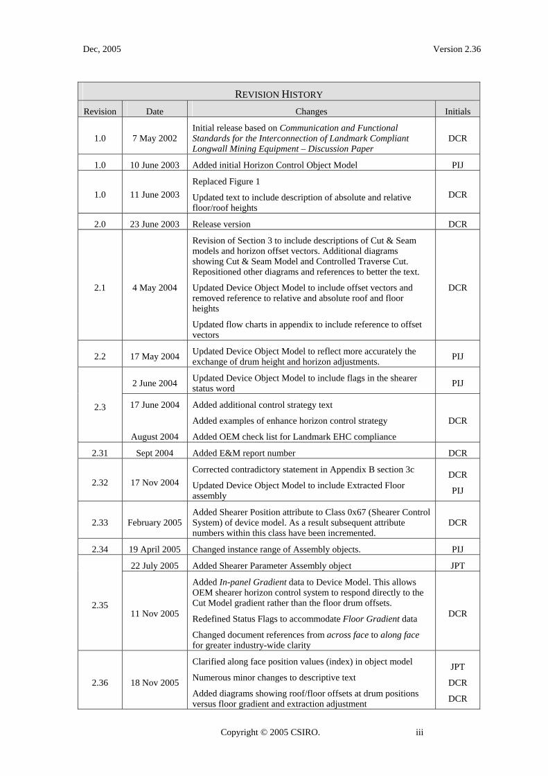
REVISION HISTORY Revision Date Changes Initials
1.0 7 May 2002 Initial release based on Communication and Functional Standards for the Interconnection of Landmark Compliant Longwall Mining Equipment – Discussion Paper
DCR
1.0 10 June 2003 Added initial Horizon Control Object Model PIJ
1.0 11 June 2003 Replaced Figure 1
Updated text to include description of absolute and relative floor/roof heights
DCR
2.0 23 June 2003 Release version DCR
2.1 4 May 2004
Revision of Section 3 to include descriptions of Cut & Seam models and horizon offset vectors. Additional diagrams showing Cut & Seam Model and Controlled Traverse Cut. Repositioned other diagrams and references to better the text.
Updated Device Object Model to include offset vectors and removed reference to relative and absolute roof and floor heights
Updated flow charts in appendix to include reference to offset vectors
DCR
2.2 17 May 2004 Updated Device Object Model to reflect more accurately the exchange of drum height and horizon adjustments. PIJ
2 June 2004 Updated Device Object Model to include flags in the shearer status word PIJ
2.3 17 June 2004
August 2004
Added additional control strategy text
Added examples of enhance horizon control strategy
Added OEM check list for Landmark EHC compliance
DCR
2.31 Sept 2004 Added E&M report number DCR
2.32 17 Nov 2004 Corrected contradictory statement in Appendix B section 3c
Updated Device Object Model to include Extracted Floor assembly
DCR
PIJ
2.33 February 2005 Added Shearer Position attribute to Class 0x67 (Shearer Control System) of device model. As a result subsequent attribute numbers within this class have been incremented.
DCR
2.34 19 April 2005 Changed instance range of Assembly objects. PIJ
22 July 2005 Added Shearer Parameter Assembly object JPT
2.35 11 Nov 2005
Added In-panel Gradient data to Device Model. This allows OEM shearer horizon control system to respond directly to the Cut Model gradient rather than the floor drum offsets.
Redefined Status Flags to accommodate Floor Gradient data
Changed document references from across face to along face for greater industry-wide clarity
DCR
2.36 18 Nov 2005
Clarified along face position values (index) in object model
Numerous minor changes to descriptive text
Added diagrams showing roof/floor offsets at drum positions versus floor gradient and extraction adjustment
JPT
DCR
DCR
Copyright © 2005 CSIRO. iii

Dec, 2005 Version 2.36
Contents
Introduction .................................................................................................................................................... ii
1. Overview .....................................................................................................................................................7
1.1 Landmark project overview...................................................................................................................7
1.2 Scope and purpose.................................................................................................................................7
2. Ethernet/IP overview...................................................................................................................................8
2.1 Layer 1 Physical Layer......................................................................................................................10
2.2 Layer 2 Data Link Layer ...................................................................................................................10
2.3 Layer 3 and 4 Network and Transport Layers...................................................................................10
2.4 Layer 7 Application layer..................................................................................................................10
3. The Enhanced Horizon Control system....................................................................................................10
3.1 The Control Strategy ...........................................................................................................................11
3.2 Batch-Mode and Real-Time Horizon Adjustment...............................................................................17
3.3 Control Loop Block Diagram..............................................................................................................18
3.4 Summary of Functional Requirements ................................................................................................19
3.5 Landmark Data Models .......................................................................................................................20
4. Shearer Enhanced Horizon Control EIP Device Model and Operation ..................................................22
Appendix A: Shearer Enhanced Horizon Control System Device Object Model. ........................................23
A.1. Ethernet/IP Device Description .............................................................................................................23
A.2. Object Model .........................................................................................................................................23
A.3. How Objects Affect Behaviour .............................................................................................................24
A.4. Defining Object Interfaces ....................................................................................................................24
A.5. Device Operation...................................................................................................................................25
A.6. Core Object Classes...............................................................................................................................27
A.6.1. Class 0x01 – Identity Object ..........................................................................................................27
A.6.2. Class 0xF5 – TCP/IP Interface Object ...........................................................................................27
A.6.3. Class 0xF6 – Ethernet Link Object.................................................................................................27
A.6.4. Class 0x04 – Assembly Object.......................................................................................................27
A.7. Application Specific Class.....................................................................................................................32
A.7.1. Class 0x67 – Shearer Control System ............................................................................................32
Copyright © 2005 CSIRO. iv

Dec, 2005 Version 2.36
Appendix B: OEM Checklist for Achieving Landmark Enhanced Horizon Control Compatibility .............35
Copyright © 2005 CSIRO. v


Dec, 2005 Version 2.36
Interconnection of Landmark Compliant Longwall Mining Equipment – Shearer Communication and Functional Specification for Enhanced Horizon Control
1. Overview
1.1 Landmark project overview
The Landmark project is an initiative of the Australian coal mining industry through the Australian Coal Association Research Program (ACARP). The aim of the project is to develop an integrated longwall automation system, comprising existing longwall equipment and advanced sensor technology that will reliably carry out the routine functions of cutting and loading coal, maintaining face geometry and in-seam horizon and manipulating roof supports without human intervention.
This document provides specifications for achieving communications and functional interconnectability between control elements of the Landmark longwall automation project. As part of the Landmark automation strategy, existing OEM longwall mining equipment form a necessary and integral part of the overall control system. Some additional components have been developed that are specific to the Landmark automation system. A key objective of this project is to achieve interoperability: not only between the control system components developed as part of this project but to ensure that the system will operate with a broad mix of commonly used longwall mining equipment.
1.2 Scope and purpose
The Landmark automation control system comprises six major components and will be implemented over a three year period. The six major components are:
1. Face Alignment
2. Enhanced Horizon Control
3. Communications and Operator Interface
4. Information Systems
5. Collision Avoidance
6. Condition Monitoring
The project components are functionally separate but have commonality at the device and control system level. To achieve the goal of system openness and component interoperability it is necessary to define a control and communication specification for Landmark compliant equipment that is generally applicable across the six components. At the communication and control level, the protocol for the interconnection of all Landmark compliant devices will be Ethernet/IP.
Copyright © 2005 CSIRO. 7
Dec, 2005 Version 2.36
The technical detail in this particular document relates specifically to the longwall shearer control system which is a key element of the Landmark Enhanced Horizon Control (EHC) (Landmark project component 2).
2. Ethernet/IP overview
The requirement for complete interoperability between all modules in the Landmark automation system dictates a common communication protocol (and physical link where possible). The communication and control protocol for Landmark compliant devices will be Ethernet/IP (IP stands for Industrial Protocol not Internet Protocol). Ethernet/IP is an open-system industrial protocol which builds on standard Ethernet technology combined with the Common Industrial Protocol (CIP, formerly referred to as Control and Information Protocol) component of DeviceNet. Ethernet/IP is managed by ODVA (Open DeviceNet Vendor Association, www.odva.org) and CI (ControlNet International).
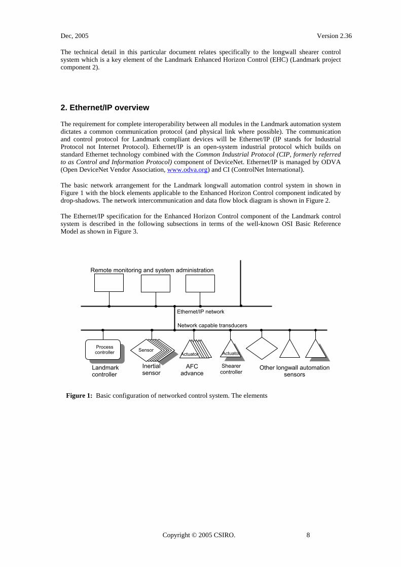
The basic network arrangement for the Landmark longwall automation control system in shown in Figure 1 with the block elements applicable to the Enhanced Horizon Control component indicated by drop-shadows. The network intercommunication and data flow block diagram is shown in Figure 2.
The Ethernet/IP specification for the Enhanced Horizon Control component of the Landmark control system is described in the following subsections in terms of the well-known OSI Basic Reference Model as shown in Figure 3.
Landmark controller
Inertial sensor
Actuator
Network capable transducers
Ethernet/IP network
Actuator Process controller Sensor
Remote monitoring and system administration
Shearer controller
AFC advance
Other longwall automation sensors
Figure 1: Basic configuration of networked control system. The elements
Copyright © 2005 CSIRO. 8

Dec, 2005 Version 2.36
Shearer Controller horizon control system
Position ActuatorEthernet/IP Server
Equipmentspecific
implementation
WirelessEthernet
10BaseTEthernet
Inertial NavigationSystem
Equipmentspecificprotocol
Extracted floor horizon
Shearer rangingarm position
Landmark "Cut Model"
Process ControllerEthernet/IP Client
Landmark Shearer Position
Measurement System
Position SensorEthernet/IP Server
LandmarkCoal Interface
and seam trackingsensors
Roof drum height information
Figure 2: Block diagram of network intercommunications and data flow for the Landmark Enhanced Horizon Control system
Figure 3: Seven layers of the well-known OSI Basic Reference Model
Copyright © 2005 CSIRO. 9

Dec, 2005 Version 2.36
2.1 Layer 1 Physical Layer
The Ethernet/IP specification makes provision for the use of copper shielded and unshielded twisted pair (Cat 5) cable and fibre optic cable at data rates up to 100Mbps. The specification does not preclude the use of other Ethernet compliant link media such as wireless Ethernet.
The physical link between the Landmark Controller and Enhanced Horizon Control devices will be Category 5 shielded twisted pair (STP) copper cable and sealed RJ45 variant connectors all meeting the requirements described in Volume 2: Ethernet/IP Adaptation of CIP Chapter 8. Wireless Ethernet will be used for network segments where physical cable is undesirable or impractical – in particular for the segment portion between the fixed roof support structure and the moving shearer.
2.2 Layer 2 Data Link Layer
The data link between the Landmark Controller and the Enhanced Horizon Control devices will be 10Mbps Ethernet, (10BaseT) as described by the IEEE 802.3 specification.
2.3 Layer 3 and 4 Network and Transport Layers
The communications channel between the Landmark Controller and the Enhanced Horizon Control devices will support User Datagram Protocol (UDP) and Transport Control Protocol/Internet Protocol (TCP/IP).
2.4 Layer 7 Application layer
The communications channel between the Landmark Controller and the Enhanced Horizon Control devices will support the Common Industrial Protocol (CIP) application layer as described by Volume 1: CIP Common Specifications and Volume 2: Ethernet/IP Adaptation of CIP Specifications.
3. The Enhanced Horizon Control system
The objective of Component 2 of the Landmark project is to achieve enhanced horizon control (EHC). The enhanced horizon control system utilizes real-time information from navigation sensors, coal interface detectors, seam tracking sensors and off-line geological and geotechnical information. All the available information is combined into two main data sets or models – the Cut Model and the Seam Model. The Cut Model is central to the Landmark control strategy and represents a dynamically updated 3D model of the as-mined roof and floor and coal seam boundaries. A detailed description of the Cut Model and Seam Model is provided in Section 3.5
In the Landmark EHC control strategy it is a requirement that the OEM shearer controller can maintain continuous repeated-cut horizon control for both the floor and roof drum independent to, and in the absence of, Landmark horizon adjustment information. The Landmark horizon adjustment information is in the form of roof and floor horizon offsets and alternatively absolute floor gradient information in the in-panel (longwall retreat) direction. This information represents the recommended horizon corrections, at incremental along-face positions for both floor and roof, that the shearer controller should make as an adjustment to the OEM repeated-cut horizon control. The Landmark horizon adjustments attempt to replicate the corrective action a shearer operator would take to adjust the floor and/or roof horizon when visually monitoring a shearer operating under OEM continuous repeated cut. The Landmark EHC control strategy is covered in more detail in Section 3.1.
Copyright © 2005 CSIRO. 10

Dec, 2005 Version 2.36
3.1 The Control Strategy
The Landmark Process Controller generates roof and floor horizon adjustments based on the Cut Model (which includes coal interface measurement, seam tracking and manual input) and this information is provided to the Shearer Controller as floor and roof horizon offsets as shown in Figure 4 or alternatively roof offsets and in-panel floor absolute gradient values as shown in Figure 5. A set of horizon adjustments is generated for each 0.5m increment of shearer along-face position. The horizon offset information comprises four values;
1.) Recommended floor offset corresponding to the current position of the main gate drum,
2.) Recommended roof offset corresponding to the current position of the main gate drum,
3.) Recommended floor offset corresponding to the current position of the tail gate drum, and
4.) Recommended roof offset corresponding to the current position of the tail gate drum.
The in-panel floor gradient information comprises two values;
1.) Recommended absolute in-panel floor gradient at the current shearer position
2.) Recommended roof offset at the current shearer position
The horizon offsets represent the adjustments that should be made by the OEM horizon control system and replicate the corrective action a shearer operator would take to adjust the floor and/or roof horizon when visually monitoring a shearer operating under OEM continuous repeated cut control. Alternatively the in-panel floor gradient vector describes the recommended horizon angle in the face-advance (longwall retreat) direction relative to horizontal. The gradient control strategy relies on the OEM horizon control system to independently achieve the recommended gradient. In this regard the OEM control system may be assisted by utilizing the high quality shearer pitch and roll data available directly from the SPMS as described in the Landmark specification Interconnection of Landmark Compliant Longwall Mining Equipment – Shearer Communication Specification for OEM-Accessible Inertial Sensor Data.
It is acknowledged that there are differences between existing OEM repeated-cut shearer horizon control systems in operation, implementation and performance. In order to use the Landmark horizon control adjustments the OEM horizon control system needs to provide a minimum level of functionality. The minimum required functionality is described in this section.
floor offset at TG(MG) drum position
roof offset at TG(MG) drum position
roof offset at MG(TG) drum
floor offset at MG(TG) drum position
null horizon
previous extraction height at MG & TG drum positions
index reference
Figure 4: Diagram describing the four elements of the floor and roof horizon offsets indexed at each 0.5m increment of shearer along-face position. Note that the data is indexed to the centre line of the shearer however the elements correspond to horizon adjustments at the maingate and tailgate drum positions
Copyright © 2005 CSIRO. 11

Dec, 2005 Version 2.36
extraction height
offset
index reference
previous extraction height
θ floor gradient
index reference
Figure 5: Diagram describing the in-panel floor gradient horizon adjustment data. This is comprised of two elements: floor gradient and extraction height offset and is provided as an alternative to the horizon offsets shown in Figure 4. The data is indexed at each 0.5m increment of shearer along-face position and the elements correspond to horizon adjustments at this position.
3.1.1 OEM-independent horizon control requirements
The Landmark Enhanced Horizon Control system acts in an advisory role as a supplement to existing OEM repeated-cut horizon control systems. The Landmark EHC will not directly control the ranging arms or any shearer functions and the ultimate responsibility for ensuring that the shearer operates within the manufacturer’s designed safety and control envelopes always remains with the OEM shearer control system.
There is a fundamental requirement that, in the absence of any external input (manual operator or Landmark adjustments), the floor drum will automatically maintain a null horizon position throughout the current shear cycle so as not to introduce a step up or down in the floor between successive shear cycles. By virtue of the constant roll of the shearer, maintaining a null floor horizon will more or less achieve a constant horizon gradient in the in-panel (longwall retreat) direction.
However a null horizon does not mean that the floor drum and ranging arm are fixed throughout the shear cycle. To achieve a null horizon, the OEM repeated-cut system will adjust the floor drum height throughout each shear to compensate for the over/under cut that would otherwise occur due to changes in shearer pitch and roll and the resulting lever arm effect on the extended ranging arm as the shearer negotiates along-face undulations.
There is also a basic requirement that, in the absence of any external input (manual operator or Landmark adjustments), the roof drum will automatically repeat the extraction height profile achieved during the previous shear cycle. The extraction height is typically constant but the OEM horizon control system needs to be able to automatically repeat a non-constant extraction profile.
Copyright © 2005 CSIRO. 12

Dec, 2005 Version 2.36
A
A
Shear cycle n
Shear cycle n+1
Section A – A end views Across face views
Shear cycle n+2
Shear cycle n+3
Figure 6: A simplified representation demonstrating how the OEM repeated-cut horizon control system attempts to maintain a constant horizon gradient in the in-panel direction and is therefore not responsive to higher than first-order trends in the seam horizon.
The simplified representation of Figure 6 demonstrates how the OEM repeated-cut approach achieves a constant horizon gradient in the in-panel (face-advance) direction. In practice this approach will only achieve the desired in-seam control over a small number of shear cycles as it cannot not take into account the higher than first-order trends and short-term variations in the seam horizon.
By contrast, the Landmark horizon control system uses prediction methods based on the Cut Model which incorporates a broad range of information including the recorded horizon from multiple previous shear cycles. This control strategy takes into account both linear and higher-order seam trends in the face-advance direction based on the evolving Cut Model which also includes instantaneous input from coal interface and in-seam detectors and operator input. The Landmark control strategy assumes that the OEM repeated-cut horizon control system is operating independently to the shearer and therefore the Landmark horizon adjustments describe the additional adjustments that need to be made beyond repeated-cut control. This concept is demonstrated in the simplified representations in Figure 7.
Copyright © 2005 CSIRO. 13

Dec, 2005 Version 2.36
shear cycle
Landmark horizon adjustment (at both MG and TG
drum positions)
roof offset
+ 0 -
+ 0 -
face-advance (retreat) direction
x
shearer along-face direction
Views A-A, C-C, E-E
x x
View B-B View D-D
a b c d e
at along-face shearer position x
A
A
B
B
E
E
C
C
D
D
floor gradient
+ 0 -
floor offset
Figure 7a: A simplified representation of a cross section of the longwall mining process at a single along-face position. This example demonstrates how a change in floor horizon gradient is achieved by means of the Landmark floor horizon offsets or alternatively floor gradient information in combination with the OEM repeated-cut horizon control system.
In Figure 7a we consider the case of horizon adjustment with constant extraction height. The OEM horizon control system independently maintains a constant floor horizon gradient in the face-advance direction between shear cycles a and b by maintaining a null horizon floor drum position in response to zero floor offsets from the Landmark EHC. Alternatively the OEM horizon control system may choose to actively maintain the constant floor horizon gradient in response to the constant floor gradient values. For ease of interpretation, the diagram considers the shearer at a single fixed along-face position x.
In response to changes in the seam, the Landmark EHC issues negative valued floor adjustments at the beginning of shear cycle b. In these examples we assume that the floor adjustments are constant across the entire face but in general they need not be. We also assume that the floor offset is the same for both the main gate and tail gate drum position and so only a single floor offset value is shown. During cycle b the OEM horizon control system lowers the height of the floor drum accordingly. Alternatively the OEM horizon control system may choose to respond to the change in floor gradient value which is intended to achieve the same results as the floor horizon offsets but may require adjustment of the floor drum over more than one shear cycle as determined by the OEM horizon control algorithms.
The roof drum is also lowered by the same amount in response to zero roof offsets so as to maintain the same extraction profile. In this example we can assume that the extraction profile is constant across the entire face but in general it need not be. In practice this may require adjustment of the roof drum over more than one shear cycle as determined by the OEM horizon control (constant opening) algorithms.
Copyright © 2005 CSIRO. 14

Dec, 2005 Version 2.36
The resulting step down in the floor will cause a change in the roll of the shearer when the AFC is pushed into position for shear cycle b+1 and this sets a steeper floor gradient. In practice if the required horizon adjustment is large and/or the AFC is much wider than the extraction width, the Landmark EHC (in the case of horizon offsets) or the OEN horizon control system (in the case floor gradients) will attempt to make this adjustment over multiple of shear cycles.
The OEM horizon control system independently maintains the new floor gradient between shear cycles c and d by maintaining a null floor drum position in response to zero floor offsets from the Landmark EHC. In response to changes in the seam, the Landmark EHC issues positive valued floor adjustments at the beginning of shear cycle d. During cycle d the OEM horizon control system raises the height of the floor drum accordingly. Alternatively the OEM horizon control system may choose to respond to the change in floor gradient value which is intended to achieve the same results as the floor horizon offsets but may require adjustment of the floor drum over more than one shear cycle as determined by the OEM horizon control algorithms. The roof drum is also raised by the same amount in response to zero roof offsets so as to maintain the same extraction profile. In practice this may require adjustment of the roof drum over more than one shear cycle as determined by the OEM horizon control (constant opening) algorithms.
The resulting step up in the floor will cause a change in the roll of the shearer when the AFC is pushed into position for shear cycle d+1 and this sets the new shallower floor gradient. The OEM horizon control system maintains the new floor gradient beyond shear e.
x
Views A-A, C-C, E-E
x x
View B-B View D-D
+ 0 -
+ 0 -
a b c d e shear cycle
at along-face shearer position x
face-advance (retreat) direction
shearer along-face direction
Landmark horizon adjustment (at both MG and TG
drum positions)
A
A
B
B
C
C
D
D
E
E
floor gradient
+ 0 -
roof offset
floor offset
Figure 7b: A simplified representation of a cross section of the longwall mining process at a single along-face position. This example demonstrates how a constant horizon gradient and a change in the extraction height is achieved by means of the Landmark roof horizon offsets in combination with the OEM repeated-cut horizon control system.
Copyright © 2005 CSIRO. 15

Dec, 2005 Version 2.36
In Figure 7b we consider the case of a constant floor horizon and a varying extraction height. The OEM horizon control system maintains a constant floor gradient throughout the example by maintaining a null horizon floor drum position in response to zero floor offsets and constant floor gradient values from the Landmark EHC. In response to changes in the upper seam boundary, the Landmark EHC issues negative valued roof offsets at the beginning of shear cycle b. In all the examples we can assume that the roof offsets are constant across the entire face but in general they need not be. We also assume that the roof offset is the same for both the main gate and tail gate drum position and so only a single roof offset value is shown.
During cycle b the OEM horizon control system lowers the height of the roof drum to achieve the reduced extraction height. The floor drum maintains the null horizon position and so there is no step in the floor and no subsequent change in the floor gradient. In addition to responding to roof offsets during cycle b, the OEM horizon control system records the new extraction height profile for independent replication during subsequent shear cycles..
The OEM horizon control system maintains the floor gradient and new extraction height profile between shear cycles b+1 and d by maintaining a null floor drum position and repeating the new extraction height profile in response to zero floor and roof offsets from the Landmark EHC. In response to changes in the upper seam boundary, the Landmark EHC issues positive valued roof offsets at the beginning of shear cycle d. During cycle d the OEM HC system raises the height of the roof drum to achieve the increased extraction height. The floor drum maintains the null horizon position and the OEM horizon control system records the new extraction height profile during cycle d and independently maintains this new extraction height profile during subsequent shear cycles.
Copyright © 2005 CSIRO. 16

Dec, 2005 Version 2.36
x
x
View C-C
View D-D
+ 0 -
+ 0 - a shear cycle b c d e f
x
Views A-A, F-F
x
x
View B-B
View E-E
at along-face shearer position x
shearer along-face direction
A
A
B
C
F
F
C
D
D
E
E
Landmark horizon adjustment (at both MG and TG
drum positions)
B
face-advance (retreat) direction
+ 0 -
floor gradient
floor offset
roof offset
Figure 7c: A simplified representation of a cross section of the longwall mining process at a single along-face position. This example demonstrates how a change in floor horizon gradient and in the extraction height are achieved by means of the Landmark floor and roof horizon offsets and/or floor gradient information in combination with the OEM repeated-cut horizon control system.
Figure 7c demonstrates the required response of the OEM HC system to both floor and roof horizon adjustments and follows a logical combination of the descriptions given for Figures 7a and 7b.
3.2 Batch-Mode and Real-Time Horizon Adjustment
The calculation of Landmark horizon adjustments is based on information from a number of sources including the inertial navigation system, coal interface detectors and seam tracking sensors. Some of this information is available in real time and therefore allows real-time horizon control. Other information is only available at fixed points in the shear cycle and is used for prediction rather than real-time control. To accommodate this, the Landmark EHC system makes provision for both real-time and batch mode transfer of the horizon adjustments to the OEM horizon control system. Batch mode transfers occur when the shearer reaches each gate-end and involves a vector of adjustments describing
Copyright © 2005 CSIRO. 17

Dec, 2005 Version 2.36
each and every along-face position. The vector is Landmark’s prediction of the required horizon adjustment throughout the next shear cycle.
During each shear cycle, the Landmark EHC uses real-time sensor information to refine the previously issued batch mode horizon adjustments. When available, this updated horizon information can be provided to the OEM horizon control system as a single set of offsets corresponding to a single along-face position. The updated information overrides any previously issued information for the current shear and should be used wherever possible by the OEM horizon control system.
3.3 Control Loop Block Diagram
The closed-loop control block diagram of the Landmark EHC system is shown in Figure 8. The output of the control system is the extracted roof and floor horizons. The floor horizon is measured by the Landmark shearer position measurement systems (SPMS which includes the inertial navigation system) and the roof is located relative to the floor based on shearer attitude and drum height measurements supplied by the shearer controller. The roof and floor horizon and seam localization information is fed into the Cut Model. From the Cut Model and any manual input, the Landmark process controller makes a prediction of what the next roof and floor horizon should be. In parallel, the Landmark process controller calculates the floor and roof horizons that should be achieved independently by the OEM repeated-cut horizon control. The Landmark horizon adjustments are then computed as the difference between these two values and are then provided to the OEM shearer controller for use during the next shear cycle.
The closed-loop form of this control system ensures that any external disturbances will be measured and corrected in subsequent shear cycles. The concept of horizon offsets ensures that the Landmark EHC will default to the standard OEM horizon control system in the absence of Landmark information.
Extracted floor and roof horizon
Manual input
++
Shearer position, attitude and drum height information
Cut Model
Manual override Coal interface input
Other seam informationSystem disturbance
Landmark floor horizon and roof
prediction. OEM shearer
control systemLandmark
calculation of OEM “Repeated Floor
and Roof Horizon”
+
_
Floor/roof horizon adjustments
Figure 8: Enhanced horizon control basic control system block diagram. The diagram describes the process of predicting the desired floor and roof extraction horizon for the next shear cycle.s
Copyright © 2005 CSIRO. 18

Dec, 2005 Version 2.36
3.4 Summary of Functional Requirements
The general functional requirements of the Landmark and OEM horizon control system are as follows
1. The OEM shearer horizon control system must be able to provide a repeated-cut horizon control strategy without reference to the Landmark horizon adjustment information. This repeated-cut must operate continuously from one shear cyle to the next without operator input. High-accuracy shearer pitch and roll information is available directly from the SPMS equipment to assist the OEM shearer control system. The OEM repeated-cut horizon control system will achieve the following
i. Ability to independently maintain a null horizon floor drum position between successive shear cycles. This means that that in response to zero-valued or no Landmark floor offsets, the OEM horizon control system will achieve a floor horizon with no step change from one shear cycle to the next. Alternatively the Landmark floor gradient information can be used to actively maintain the required in-panel gradient.
ii. Ability to maintain a fixed and constant extraction height relative to the floor when operating in a fixed extraction height mode. When operating in this mode, the OEM horizon control system will ignore Landmark roof offset information. Furthermore, an adjustment in the floor drum height, at any given along-face position in response to Landmark floor offsets or floor gradient information will produce an equal adjustment in the roof height so as to maintain the fixed extraction height.
iii. Ability to replicate an extraction height profile (constant or otherwise) from one shear cycle to the next. When not in a constant extraction height mode, the OEM horizon control system will adjust the extraction height in response to Landmark roof offset information. Furthermore this new extraction height profile will be replicated in subsequent shear cycles and any subsequent Landmark roof offsets will be applied as offsets from this new extraction height profile.
2. The Landmark Controller will provide horizon adjustment informatio to the Shearer Controller corresponding to each 0.5 metre increment of along-face distance referenced to the centre line of the shearer.
i. The OEM Shearer Controller will adjust the floor drum in response to either
1. floor horizon offset information provided by the Landmark Controller (as shown in Figure 4) or
2. required in-panel floor gradient information provided by the Landmark Controller (as shown in Figure 5)
ii. The OEM Shearer Controller will adjust the floor drum in response to either
1. roof horizon offset information provided by the Landmark Controller (as shown in Figure 4) or
2. extraction height adjustment information provided by the Landmark Controller (as shown in Figure 5)
3. The Shearer Controller is responsible for ensuring that the horizon control information provided by the Landmark Controller does not cause the shearer to operate outside the designed safety and control envelope.
Copyright © 2005 CSIRO. 19

Dec, 2005 Version 2.36
4. In the absence of valid horizon control information from the Landmark Controller, the Shearer Controller will assume zero valued horizon offsets and unchanged floor gradient and therefore default to standard repeated-cut or manual control.
5. All existing functions of the Shearer Controller, including safety systems and timing and sequencing remain the responsibility of the Shearer Controller.
6. The Shearer Controller will provide instantaneous ranging arm height and system status information as requested by the Landmark Controller.
An OEM implementation checklist for achieving compatibility with the Landmark Enhanced Horizon Control is included in Appendix B
3.5 Landmark Data Models
3.5.1 The Cut Model
The Cut Model is the primary input to the Landmark horizon control system. It incorporates coal seam information such as extraction profiles, coal interface and seam tracking measurements obtained during the extraction process. The Cut Model locates the extracted volume in three-dimensional space and locates this volume relative to the seam boundaries. The data is sampled on a relatively dense grid and can be quite accurate.
The Cut Model data describes four surfaces a. the extracted floor b. the extracted roof c. the upper seam boundary d. the lower seam boundary
Examples of these surfaces are shown in Figure 9. The solid dots represent points of three-dimensional position as measured by the shearer position measurement system (which includes the inertial navigation system) to provide the extracted floor horizon. This extracted floor surface is measured as absolute position in three-dimensional space and provides the model datum. All the other surfaces are then located relative to the floor. The extracted roof horizon (as indicated by the fine continuous line) is obtained from shearer cutting drum height and attitude information. The upper and lower seam boundaries (thick dashed lines) are obtained from coal interface and seam tracking measurements which locate the boundaries relative to the floor and roof horizons.
Copyright © 2005 CSIRO. 20

Dec, 2005 Version 2.36
Upper and lower seam boundaries from Cut Model
Extracted roof and floor horizons from Cut Model
Upper and lower seam boundaries from Seam Model
Figure 9: Diagram of partly mined longwall panel. The open arrow indicates the direction of face advance (longwall retreat). The solid dots describe the elevation of the extracted floor as measured by the SPMS. The open dots represent the predicted floor horizon for the next shear cycle. The upper and lower coal boundaries are indicated by the heavy dashed line. In the expanded view, the open dot and connected solid line represents the predicted floor horizon during the next shear cycle as determined by extrapolation.
3.5.2 The Seam Model
The Seam Model incorporates coal seam information obtained from historical data such as bore logs, seismic and roadway survey data to locate the un-mined seam in three-dimensional space. The Seam Model data is only sparsely sampled and may be quite inaccurate. The Seam Model is primarily used for data visualization and does not directly form part of the Landmark Enhanced Horizon Control system.
The Seam Model can provide the horizon control system with information about abnormal or extreme geology which produce abrupt changes in the vertical location of the coal seam. These geological conditions could not be predicted directly from the Cut Model. However these conditions may be detected by comparing the Seam Model with the seam predictions based on the Cut Model. Any significant disagreement between the two models could indicate that operator intervention is required.
Automated horizon control through a region of vertical discontinuity could still be achieved using a Controlled Traverse Cut. This facility allows the operator to define a transitional horizon surface via a graphical user interface. Figure 10 illustrates the use of a Controlled Traverse Cut to transition through a seam discontinuity. A seam discontinuity is shown immediately ahead of the shearer in the face advance direction as indicated by the open arrow. The solid dots represent the extracted floor horizon,
Copyright © 2005 CSIRO. 21

Dec, 2005 Version 2.36
the solid squares represent the sparse data points from the Seam Model and the solid triangles represent the operator-specified Controlled Traverse Cut. The allowable shape of the Controlled Traverse Cut would be restricted so as not to exceed the operational limits of the equipment.
Figure 10: Diagram showing an example of a Controlled Traverse Cut to provide transitional horizon control through a region of extreme geology (eg seam fault). The solid dots describe the elevation of the extracted floor as measured by the SPMS. The solid squares represent the coal seam lower boundary as obtained from sparsely distributed mine site data. The solid triangles represent a user-specified horizon surface which transitions along the fault while remaining within equipment operational limits.
4. Shearer Enhanced Horizon Control EIP Device Model and Operation
The Ethernet/IP device object model for the Shearer Enhanced Horizon Control system is detailed in Appendix A. Flowcharts A.2 and A.3 describe the control and processing steps for the Landmark Controller and Enhanced Horizon Control system through one shear half-cycle.
Copyright © 2005 CSIRO. 22

Dec, 2005 Version 2.36
Appendix A: Shearer Enhanced Horizon Control System Device Object Model.
A.1. Ethernet/IP Device Description
Longwall Shearer Enhanced Horizon Control System (Generic Device). Ethernet/IP Device Type 0x00
A.2. Object Model
Object Class ID Object Class Name Number of Instances
0x01 Identity Object 1
0x02 Message Router Object No Attribute Data
0x04 Assembly Object 2
0x06 Connection Manager Object No Attribute Data
0x67 Shearer Control System 1
0xF5 TCP/IP Interface Object 1
0xF6 Ethernet Link Object 1
Copyright © 2005 CSIRO. 23

Dec, 2005 Version 2.36
Connection Class
Message Router
Identity O b j e c t
I/O ExplicitMsg.
EtherNet/IP Network
Assembly Object
I / P O / P
E t h e r N e t L i n k O b j e c t
TCP/IP Int e r f a c e
Objec t
Shearer Object
Figure A.1: Object model for the Longwall Shearer Enhanced Horizon Control system
A.3. How Objects Affect Behaviour
As described for Generic Device in Volume 1: CIP Common Specifications, Chapter 6, Section 6-8.2
A.4. Defining Object Interfaces
As described for Generic Device in Volume 1: CIP Common Specifications, Chapter 6, Section 6-8.3
Copyright © 2005 CSIRO. 24

Dec, 2005 Version 2.36
A.5. Device Operation
Start
Computed from INS vertical, shearer drum height and attitude,and other sensor information collected over previousshear cycles.
Has shearer moved to next
across-faceposition?
Has shearercompleted a half
cycle?
Compute prediction ofthe Enhanced HorizonControl profile for next
shear half cycle
Update horizon offset values for next shear
half cycle
Get() real-time INSand CID information
Update RFH and RRHvalues for present
across-face position
yes yes
no no
Figure A.2: Flow chart of Landmark Controller interaction with Longwall Shearer Enhanced Horizon Control system through one half shear cycle.
Copyright © 2005 CSIRO. 25

Dec, 2005 Version 2.36
Start
Control drum heights to achievenew horizon
noHas shearer
moved to nextacross-faceposition?
Read Landmarkhorizon offset values
for current across-faceposition
Compute adjustedpositions for the
maingate and tailgatedrums
Are computeddrum positionswithin control
envelope?
yes
yes
no
Figure A.3: Flow chart of Longwall Shearer Enhanced Horizon Control system interaction with Landmark Controller through one half shear cycle
Copyright © 2005 CSIRO. 26

Dec, 2005 Version 2.36
A.6. Core Object Classes
The following Core Object Classes will have supported attributes and services.
A.6.1. Class 0x01 – Identity Object Class Attributes
Class Attribute ID 1 (Revision) will be implemented
Instance Attributes
All required Instance Attributes (ID 1 – ID 7 inclusive) will be implemented.
A.6.2. Class 0xF5 – TCP/IP Interface Object
Class Attributes
Class Attribute ID 1 (Revision) will be implemented Instance Attributes
All required Instance Attributes (ID 1 – ID 6 inclusive) will be implemented.
A.6.3. Class 0xF6 – Ethernet Link Object Class Attributes
Class Attribute ID 1 (Revision) will be implemented
Instance Attributes
All required Instance Attributes (ID 1 – ID 3 inclusive) will be implemented.
A.6.4. Class 0x04 – Assembly Object
Four static instances of the assembly object will be implemented. Instance number 101, 102, 103 and 104.
Class Attributes
No class attributes are required.
Instance Attributes
Three instances are required. Either instance 101 (floor and roof offsets for the next pass across the face) or alternatively instance 104 (in-panel gradients and roof offsets for the next pass across the face), instance 102 (extracted floor heights for the previously completed pass
Copyright © 2005 CSIRO. 27

Dec, 2005 Version 2.36
across the face) and instance 103 (instantaneous shearer parameters). Instances 101, 102 and 104 are output instances, which mean they are to be set by the client, not by the server. Instance 103 is an input instance. Instance 101: Horizon Adjustment
If requested by the server via the status flag, the server will accept a vector of horizon adjustment structures at the beginning of each shear half cycle (i.e. once at the main gate and once at the tail gate). This is the initial set of horizon adjustments, which may be refined and updated as the shearer traverses the face (see class 0x67 Shearer Control System).
The number of horizon adjustment structures, and hence the size of the Assembly Object Data attribute, is related to the width of the face. The vector will contain one horizon adjustment structure (5 INTs which is 10 bytes of data) for each 0.5m of face width from 0m to (Panel Width)m plus the sequence number (2 bytes). The size of the Assembly Object Data attribute is: 2 + (Panel Width [m] * 2 + 1) * 10 bytes.
For example, if the panel is 100m wide, then there will be a sequence number and 201 horizon adjustments in the Assembly Object Data attribute, which is 2 + 201 * 10 = 2012 bytes.
Each vector of horizon adjustments has a unique sequence number associated with it. Under normal operation a new horizon adjustment vector will be computed at the end of each shear half cycle (maingate or tailgate) and will describe the recommended horizon adjustment for the next half cycle. The sequence number will refer to the just completed half cycle. If the sequence number of a horizon adjustment vector is the same as a previously received vector, then the data contained in the vector is stale and should be discarded.
Attr ID Implementation Access Name Data Type Description of
Attribute
Semantics of Value
Horizon Adjustment vector
STRUCT of
Struct includes elements from Sequence Number through to Roof Offset Tailgate.
Sequence Number INT Each Horizon Adjustment vector has a unique sequence number
Negative sequence numbers indicate invalid data. Usually starts at 0 and increments for each face traversal
Horizon Adjustment ARRAY of STRUCT:
Struct includes elements from Floor Offset Maingate through to Roof Offset Tailgate
Index UINT Position along face 0.5m increments along face from main gate i.e. indexx * 0.5m = position in meters
Floor horizon offset corresponding to maingate end drum
INT As described in Figure 4
In mm
Roof horizon offset corresponding to maingate end drum
INT As described in Figure 4
In mm
Floor horizon offset corresponding to tailgate end drum
INT As described in Figure 4
In mm
3 Required Set
Roof horizon offset corresponding to tailgate end drum
INT As described in Figure 4
In mm
Copyright © 2005 CSIRO. 28

Dec, 2005 Version 2.36
Instance 102: Extracted Floor Heights
If requested by the server via the status flag, the server will accept a vector of extracted floor structures at the beginning of each shear half cycle (i.e. once at the main gate and once at the tail gate). This vector describe the height of the extracted floor at fixed 0.5m increments between the maingate and tailgate recorded during the last completed shear cycle relative to the vertical offset level. This means that the first extracted floor value (corresponding to the maingate 0m position) will be zero. Adding the vertical offset value to the extracted floor values will provide the extracted floor height relative to the overall longwall panel vertical reference point.
The number of extracted floor structures, and hence the size of the Assembly Object Data attribute, is related to the width of the face. The vector will contain one extracted floor structure (2 INTs which is 4 bytes of data) for each 0.5m of face width from 0m to (Panel Width)m plus the sequence number (2 bytes) and the vertical offset (4 bytes). The size of the Assembly Object Data attribute is: 6 + (Panel Width [m] * 2 + 1) * 4 bytes.
For example, if the panel is 100m wide, then there will be a sequence number and 201 extracted floor values in the Assembly Object Data attribute, which is 6 + 201 * 4 = 810 bytes.
Each extracted floor vector has a unique sequence number associated with it which for each shear cycle will be the same as the horizon adjustment sequence number. Under normal operation a new extracted floor vector will be computed at the end of each shear half cycle (maingate or tailgate) and will describe the height of the extracted floor as measured during the just completed half cycle. The sequence number will refer to the just completed half cycle. If the sequence number of an extracted floor vector is the same as a previously received vector, then the data contained in the vector is stale and should be discarded.
Attr ID Implementation Access Name Data Type Description of
Attribute
Semantics of Value
Extracted Floor Vector
STRUCT of
Struct includes elements from Sequence Number through to Relative Height
Sequence Number INT Each Extracted Floor vector has a unique sequence number
Negative sequence numbers indicate invalid data. Usually starts at 0 and increments for each face traversal
Vertical Offset DINT
The vertical offset of the first extracted floor data point relative to the longwall panel vertical reference point
In mm
Extracted Floor ARRAY of STRUCT:
Struct includes elements from Along Face Position through to Relative Height
Along Face Position UINT Position along face 0.5m increments along face
from main gate i.e. indexx * 0.5m = position in meters
3 Required Set
Relative Height INT Height of floor relative to Vertical Offset level
In mm
Copyright © 2005 CSIRO. 29

Dec, 2005 Version 2.36
Instance 103 – Shearer Parameters
The server will provide the following shearer operating parameter via this assembly object. It is expected that the server will internally update these values at 1 Hz at least. The individual parameters are not required to be updated at the same rate
Attr ID Implementation Access Name Data Type Description of
Attribute Semantics of Value
Shearer Parameters
STRUCT of The Shearer Parameter
Revision UINT Current value = 01
Shearer Position DINT
Position of shearer along the AFC from the maingate datum and referenced to the centre of the shearer.
In decimetres
Shearer Speed UINT In 0.01 m/s
Shearer Direction SINT Direction of travel of shearer along face
-1 = toward main gate, 1 = away from main gate
Cutter 1 Current UINT In mA * 100
Cutter 2 Current UINT In mA * 100
Haulage Current UINT In mA * 100
3 Required Get
Shearer Status UINT Status of Shearer Control Device
Bit pattern
Bit 0 = Horizon Adj request
Bit 1 = Data in use
Bit 2 = Data rejected
Bit 3 = Extracted Floor req.
Bit 4 = In-panel Floor Gradient and Face Opening request
Instance 104 – Floor Gradient
If requested by the server via the status flag (Bit 4), the server will accept a vector of Floor Gradient structures at the beginning of each shear half cycle (i.e. once at the main gate and once at the tail gate). This is the initial set of floor gradients and roof horizon offsets, which may be refined and updated as the shearer traverses the face (see class 0x67 Shearer Control System).
The number of Floor Gradient structures, and hence the size of the Assembly Object Data attribute, is related to the width of the face. The vector will contain one Floor Gradient structure (3 INTs which is 6 bytes of data) for each 0.5m of face width from 0m to (Panel Width)m plus the two sequence numbers (4 bytes). The size of the Assembly Object Data
Copyright © 2005 CSIRO. 30

Dec, 2005 Version 2.36
attribute is: 4 + (Panel Width [m] * 2 + 1) * 6 bytes. If too few or too many elements are received the server must respond with the EIP message 0x13 or 0x15 respectively.
The Floor Gradient structure of has two vector components: floor gradient, which describes the angle of the recommended in-panel gradient relative to horizontal; and the roof horizon offset which is equivalent to the roof horizon offsets described in the Instance 101: Horizon Adjustment assembly except that it is a single vector which is referenced to the shearer along track position rather than the maingate and tailgate drum positions.
Each Floor Gradient structure of has two unique sequence numbers associated with it. The Floor Sequence number applies to the actual floor gradient vector and the Roof Sequence number applies to the Roof Horizon Offset vector. Under normal operation a new floor gradients vector and roof horizon adjustment vector will be computed at the end of each shear half cycle (maingate or tailgate) and will describe the recommended floor gradient and roof horizon adjustment respectively for the next half cycle. The sequence numbers will refer to the just completed half cycle. If the sequence number of the floor gradient vector is the same as the previously received floor gradient vector, then the data contained in the vector is stale and should be discarded. If the sequence number of the roof horizon adjustment vector is the same as the previously received roof horizon adjustment vector, then the data contained in the vector is stale and should be discarded. A negative sequence number indicates that the associated vector contains invalid data.
Note that the Floor Sequence number and Roof Sequence number are normally the same for a given shear half cycle. However it is possible that one or both of the sequence numbers are negative valued which will indicate that the data in the associated vector is invalid.
A detailed description of the purpose and interpretation of floor gradient information is given in Section 3.1
Attr ID Implementation Access Name Data Type Description of
Attribute
Semantics of Value
Floor Gradient vector STRUCT of
Struct includes elements from Sequence Number through to Roof Offset Tailgate.
Floor Sequence Number
INT Each Floor Gradient vector has a unique sequence number
Negative sequence numbers indicate invalid data. Usually starts at 0 and increments for each face traversal
Roof Sequence Number
INT Each Roof Horizon Adjustment vector has a unique sequence number
Negative sequence numbers indicate invalid data. Usually starts at 0 and increments for each face traversal
Floor Gradient ARRAY of STRUCT:
Struct includes elements from Floor Offset Maingate through to Roof Offset Tailgate
Index UINT Position along face 0.5m increments along face from main gate i.e. indexx * 0.5m = position in meters
3 Required Set
Floor Gradient INT Absolute angle of the target in-panel floor gradient relative to horizontal as described in Figure 5
In 0.1 degrees
Negative values are below the horizon and positive values are above when considered in the direction of longwall retreat.
Copyright © 2005 CSIRO. 31

Dec, 2005 Version 2.36
Roof horizon offset corresponding to along face position
INT Roof horizon offset as described in Figure 5. Note that this value refers to the required roof horizon adjustment at the along face position described by the Index attribute
In mm
Common Services
Service Code
Implementation Name Description
Class Instance
0x0E Required Required Get_Attribute_Single Returns contents of specified attribute
0x10 N/A Required Set_Attribute_Single Writes contents of specified attribute
A.7. Application Specific Class
A.7.1. Class 0x67 – Shearer Control System Class Attributes
These attributes will reflect the attributes of the Shearer Control System that are required to be configurable over the network.
Attr ID Implementation Access Name Data Type Description of
Attribute Semantics of Value
1 Required Get Revision UINT Current value = 01
8 Required Get Shearer Position DINT
Position of shearer along the AFC from the maingate datum and referenced to the centre of the shearer.
In decimetres
9 Required Get Shearer Speed UINT
10 Required Get Shearer Direction SINT Direction of travel of shearer along face
-1 = toward main gate, 1 = away from main gate
11 Required Get Cutter 1 Current UINT In mA * 100
12 Required Get Cutter 2 Current UINT In mA * 100
13 Required Get Haulage Current UINT In mA * 100
Copyright © 2005 CSIRO. 32

Dec, 2005 Version 2.36
14 Required Get Shearer Status UINT Status of Shearer Control Device
Bit pattern
Bit 0 = Horizon Adj request
Bit 1 = Data in use
Bit 2 = Data rejected
Bit 3 = Extracted Floor req.
Bit 4 = Floor Gradient and Roof Horizon Adj request
Instance Attributes
There will be one instance of the Shearer Control System object, instance one.
Attribute 1 is the refined horizon adjustment, which is provided to the server as the shearer moves across the face. Each time attribute 1 is set, the 0.5m index should be checked to see if the incoming data is fresh enough to be used. For example, if the shearer is 20m across the face and attribute 1 is set with the Index element with a value of 39 (19.5m) or less, the horizon offsets would be stale and hence not used.
Attribute 2 is the instantaneous Floor and Roof Drum heights updated by the server every 0.5m across the face.
Attribute 3 is the extracted floor height relative to the maingate floor height. The extracted floor heights could be set individually, but normally extracted floor heights will be set as a vector using instance 102 of the Assembly object.
Attr ID
Implementation Access Name Data Type
Description ofAttribute Semantics of Value
Horizon Adjustment STRUCT of
Index INT Position along face 0.5m increments along face from main gate i.e. indexx * 0.5m = position in meters
Floor horizon offset corresponding to maingate end drum
INT In mm
Roof horizon offset corresponding to maingate end drum
INT In mm
Floor horizon offset corresponding to tailgate end drum
INT In mm
1 Required Set
Roof horizon offset corresponding to tailgate end drum
INT In mm
Drum Data STRUCT of
2 Required Get
Index UINT Position along face 0.5m increments along face from main gate i.e. indexx * 0.5m = position in meters
Copyright © 2005 CSIRO. 33

Dec, 2005 Version 2.36
Floor Drum Height INT In mm
Roof Drum Height INT In mm
Extracted Floor STRUCT of
Vertical Offset DINT
The vertical offset of the first extracted floor data point relative to the longwall panel RL
In mm
Along Face Position UINT Position along face 0.5m increments along face from main gate.
3 Required Set
Relative Height INT Height of floor relative to main gate level
In mm
Floor Gradient STRUCT of:
Struct includes elements from Floor Offset Maingate through to Roof Offset Tailgate
Index UINT Position along face 0.5m increments along face from main gate i.e. indexx * 0.5m = position in meters
Floor Gradient INT Absolute angle of the target in-panel floor gradient relative to horizontal
In 0.1 degrees
Negative values are below the horizon and positive values are above when considered in the direction of longwall retreat.
4 Required Set
Roof horizon offset corresponding to along face position
INT Roof horizon offset as described in Figure 5b. Note that this value refers to the required roof horizon adjustment at the along face position described by the Index attribute
In mm
Common Services
Service Code
Implementation Name Description
Class Instance
0x0E Required Required Get_Attribute_Single Returns contents of specified attribute
0x10 N/A Required Set_Attribute_Single Writes contents of specified attribute
Copyright © 2005 CSIRO. 34

Dec, 2005 Version 2.36
Appendix B: OEM Checklist for Achieving Landmark Enhanced Horizon Control Compatibility
1. Provide Ethernet data communication port on OEM horizon control system, supporting
a. 10Mbps (10BaseT) data link as described by IEEE802.3
b. User Datagram Protocol (UDP) and Transport Control Protocol / Internet Protocol (TCP/IP) network and transport layers
2. Develop Ethernet/IP compliant interface to Landmark Process Controller, including
a. Common Industrial Protocol (CIP) (previously referred to as Control and Information Protocol)
b. Landmark Enhanced Horizon Control device model as defined in Appendix A of this specification.
3. Ensure OEM horizon control system can provide the repeated-cut horizon control strategy described in Section 3 of this specification, independent to, and in the absence of Landmark Enhanced Horizon Control information
a. Ability to independently maintain a null floor drum position between successive cycles. This means that that in response to zero-valued or no Landmark floor information, the OEM horizon control system will achieve a floor horizon with no step change from one shear cycle to the next.
b. Ability to maintain a fixed and constant extraction height relative to the floor when operating in a fixed extraction height mode. When operating in this mode, the OEM HC system will ignore Landmark roof offset information. Furthermore, an adjustment in the floor drum height, at any given along-face position in response to Landmark floor offsets or floor gradient information will produce an equal adjustment in the roof height so as to maintain the fixed extraction height.
c. Ability to replicate an extraction height profile (constant or otherwise) from one shear cycle to the next. When not in a constant extraction height mode, the OEM horizon control system will adjust the extraction height in response to Landmark roof offset information. Furthermore this new extraction height profile will be replicated in subsequent shear cycles and any subsequent Landmark roof offsets will be applied as offsets from this new extraction height profile.
4. Develop software algorithms to utilize the horizon offset information and/or floor gradient information provided by the Landmark Process Controller as described in Section 3 of this specification.
a. Accept a single set of Landmark horizon offsets and/or floor gradients corresponding to a single along-face position. In the case of horizon offsets this will contain four values; Floor horizon offset corresponding to maingate end drum, Floor horizon offset corresponding to tailgate end drum, Roof horizon offset corresponding to maingate end drum and Roof horizon offset corresponding to tailgate end drum. In the case of floor gradient this will contain two values: Floor gradient andextraction height offsets.
b. Accept a vector of Landmark horizon offsets or alternatively floor gradients (ie., multiple sets of offsets described above) with each element of the vector corresponding to each and every increment of along-face position.
Copyright © 2005 CSIRO. 35

Dec, 2005 Version 2.36
c. Use either Floor horizon offset corresponding to maingate end drum or Floor horizon offset corresponding to tailgate end drum as appropriate depending on which drum is cutting the floor. Alternatively floor gradient information can be used in place of floor horizon offsets
d. Use either Roof horizon offset corresponding to maingate end drum or Roof horizon offset corresponding to tailgate end drum as appropriate depending on which drum is cutting the roof. Alternatively use the roof horizon offset information provided as part of the floor gradient assembly
e. If using the floor horizon offsets, apply these to achieve a corresponding step change in the floor (relative to the null horizon drum position) applied only to the single shear cycle for which the offsets were issued. The OEM horizon control system is not required to record floor horizon offset information used during one shear cycle for use in subsequent cycles.
f. Assuming the shearer horizon control system is operating in a variable extraction height mode (ie not fixed extraction), apply the Landmark roof horizon offset to achieve a corresponding change in the extraction height (relative to the floor horizon). The OEM horizon control system is required to automatically replicate the extraction height profile, including any Landmark roof horizon adjustments applicable to the current shear cycle, from one shear cycle to the next.
g. If using the floor gradient information , the OEM horizon control system can employ any floor drum adjustment strategy over a single or multiple shear cycles to achieve and/or maintain the recommended (absolute valued) floor gradient at each along. face position
Copyright © 2005 CSIRO. 36