Embed Size (px)
Citation preview

Thin-Walled Structures 12 (1991) 415--434 77--'7"=~
Interactive Buckling of Beams in Bending
C. M. Menken, W. J. Groot & G. A. J. Stallenberg
Department of Mechanical Engineering, Eindhoven University of Technology. Eindhoven, The Netherlands
(Received 11 October 1990; accepted 3 December 1990)
ABSTRACT
A discrete model involving a limited number of degrees offreedom ispresented, for analyzing the interaction between overall lateral-torsional buckling and local flange buckling, qualitatively. The results are compared with experiments and show a good qualitative agreement. The results suggest that a quantitative numerical analysis based on Koiter's asymptotic approach may have a wide range of validity.
NOTATION
a
A~j Aijk Aijkl b d E h k l P PL Po
Local buckling amplitude in the experiments Second order coefficients in V Third order coefficients in V Fourth order coefficients in V Flange width Length of link Spring stiffness Web height Stiffness of precompressed spring Length Conservative load Critical load for local buckling Critical load for overall buckling
415 Thin- Walled Structures 0263-823 i/91/$03.50 © 1991 Elsevier Science Publishers Ltd, England. Printed in Great Britain

416 C. M. Menken, W. J. Groot, G. A. J. Stallenberg
q2 Q, Q2 Q3 Q. Qs, s, UA, UB, UC
Uo 0
V W
X 0
Rotation representing incremental deflection Rotation representing torsion Rotation representing vertical deflection Rotation representing lateral deflection Shortening of original neutral axis Local buckling amplitudes in the discrete model Torsional stiffness Axial displacements Precompression of spring Lateral deflection in experiments Potential energy Vertical deflection
Half wavelength of local buckle Midspan rotation in experiments
1 INTRODUCTION
The detrimental effect that an interaction between local and overall buckling of structural members may have is well known. L2 After recognizing its symptoms, this phenomenon was investigated thoroughly for structural members under uniform compression, including stiffened plates 3 and shells, 4 and thin-walled columns. 5 The interaction between local buckling and lateral torsional buckling as a result of bending 6 has been given less attention, but it is an area of practical importance, because thin-walled built-up girders are used extensively and the use of cold-formed and extruded members is increasing. Moreover, the wall- thickness of extruded members is becoming thinner all the time.
This interaction problem was investigated in three different ways:
(1) By analyzing a simple discrete model that had only a few degrees of freedom, in order to learn more about this type of buckling.
(2) By performing interactive lateral-torsional buckling experiments, because little has been done on this subject. Some researchers even mention the scarcity of experiments, v-~
(3) By developing a spline finite-strip computer program for simulating the interactive buckling behavior of prismatic beams with arbitrary cross-sections, tll ~
The third way is based on the asymptotic approach described by Koiter; ~2 in fact, it only applies in the case of coincident or nearly coincident buckling loads. One of the aims of the experiments was to get a better
Interactive buckling of beams in bending 417
insight into its range of applicability. Since the first two ways showed a remarkably good qualitative agreement, this paper reports some of the results obtained.
2 THE DISCRETE MODEL
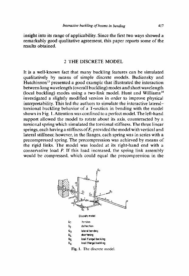
It is a well-known fact that many buckling features can be simulated qualitatively by means of simple discrete models. Budiansky and Hutchinson ~3 presented a good example that illustrated the interaction between long wavelength (overall buckling) modes and short wavelength (local buckling) modes using a two-link model. Hunt and Williams j4 investigated a slightly modified version in order to improve physical interpretability. This led the authors to simulate the interactive lateral- torsional buckling behavior of a T-section in bending with the model shown in Fig. 1. Attention was confined to a perfect model. The left-hand support allowed the model to rotate about its axis, counteracted by a torsional spring which simulated the torsional stiffness. The three linear springs, each having a stiffness of E, provided the model with vertical and lateral stiffness; however, in the flanges, each spring was in series with a precompressed spring. The precompression was achieved by means of the rigid links. The model was loaded at its right-hand end with a conservative load P. If this load increased, the spring link assembly would be compressed, which could equal the precompression in the
s ~ Q~
b E
Qs B
Y~Jx ~2
Discrete model
Q1 torsion 0"2 deflection Q3 tateral bending Q~ shorfening Q5 Iota[ (fLange) buckling 0, 6 local (flange) buckti ng
Fig. !. The discrete model.

418 C. M. Menken. W. J. Groot. G. A. J. Stallenberg
springs and cause the links to buckle. The overall lateral-torsional buckling was characterized by the rotation Q~ and the lateral bending Q3. The angles Q5 and Q6 characterized the local buckling of the flanges, angle Q2 being the vertical deflection of the beam, and displacement Q4 being a shortening of the neutral axis similar to that caused by local buckling.
In order to make this model susceptible to lateral-torsional buckling, like a real beam, its parameters had to be chosen in such a way that:
(1) the lateral and torsional stiffnesses were much smaller than the vertical stiffness,
(2) the pre-buckling deflection could be neglected, (3) the overall lateral-torsional buckling was neutral in the absence of
local buckling, (4) in the post-buckling region, the spring link assemblies behaved
like a flat plate.
The exact potential energy expression, V (Q1, Q2, Q3, Q4, Q5, Q6), was expanded in the displacements and truncated after the quartic terms. The incremental deflection q2 and the shortening Q4 would always be passive (dependent); consequently, they were eliminated. Since both Q~ and Q3 were non-zero components of the overall buckling mode, the authors chose Q3 as the amplitude and treated Qt as the passive coordinate. After eliminating these coordinates, the potential energy expression looked like (see also the Appendix):
I ") "~ "~ V(Q3, Qs, Q6) = ~A33Q~ + ~AssQg + ~A66Qa + ~A3ssQ3Q5 I "~ I 4 I A / ' 1 2 / ' 1 2 I 4
+ ~A366Q3Q~_ + ~AssssQs~ + a ~,ss66~zs~z6 + ~ A6666Q6 (1)
where A33, Ass and A66 are the buckling coefficients:
= (2b2E P212) A~ -- \ S, ]
ld As~ = (PL - P) ~ = A66
The other coefficients are:
A355 = 2bdE = - A 3 ~
Assss = 12d2(½E + k) = A~,,66
A s56~ = - 2d2 E

Interactive buckling of beams in bending 419
As a result of the above-mentioned points (3) and (4), only the local buckling amplitudes Q5 and Q6 appeared up to and including the fourth order in the potential energy expression. This expression included the symmetry-breaking coefficients A355 and A366 that might cause destabil- ization in the post-buckling region?
Finding the equilibrium paths from eqn (1) was not limited to coincident or nearly coincident buckling loads, like the continuous and discretized continuous models based on the asymptotic approach? 5, ~0 The authors focused on the situation where the local critical load PL was least: A55 = .466 = 0 < .433. In this case, there would be three equilibrium paths:
an uncoupled path, involving local buckling only:
03 = 0, Q5 = Q6 4 : 0
two coupled paths, involving interactive buckling:
03 4: 0, Q5 4: 0, Q6 = 0
Q3 4: o, Q5 = o, Q6 4 : 0
(2)
(3)
(4)
The two coupled paths are equivalent, due to the symmetry of the model. Now, we will confine ourselves to the path with Q6 = 0, i.e. when the local buckling load has been reached, the overall buckling is triggered off in such a way that the pertinent lateral bending prevents the posterior 'flange' from buckling, while buckling of the anterior 'flange' is increased. For this case the potential energy expression becomes:
V(Q3. Qs) ~A33Q 2 + 1 2 1 ~A.~sQ5 + ~_A355Q3Qg 1 4 = + ~A5555Q5 (5)
This is precisely the same expression as that for the so-called parabolic umbilic catastrophe which is a characteristic of many interactive buckling problems that have been analyzed by other investigators. Therefore, comparable behavior could be expected.
In order to decide whether path (2) or path (3) would be followed, we compared the respective potential energies in the vicinity of the bifurcation point for local buckling: A55 = A66 = 0. Then the overall buckling amplitude Q3 could also be eliminated from eqn (1), as it would be passive. From the requirement that 0 V/OQ3 = 0, the following was obtained:
A355 A ~66 ~ 2 Q3 = 2A33 Q~ - ~ (26 (6)

420 C M. Menken, W. J. Groot, G. A. J. Stallenberg
The respective potential energies became:
in the case of local buckling alone:
V(Qs) = ~ (A5555 + 3A5566)Q 4 (7)
- - in the case of interactive buckling:
A3552~4 (8) V(Qs) = ~4 A~ss5- 3 A~ 3 }set
For this model, Asss_~ = 18Ed:, Ass~ = - 2 E d 2 and the buckling coefficient A33 is positive as long as the load is smaller than the overall buckling load. Therefore, it follows that interactive buckling will minimize the potential energy more than local buckling alone. Thus, interactive buckling will dominate. In Section 4, figures of the equilibrium paths are presented diagrammatically. In the calculations, the authors chose h = 9b.
3 INTERACTIVE BUCKLING EXPERIMENTS
In the experiments, a simply supported prismatic T-beam was loaded in pure bending (Fig. 2) in such a way that, as with the discrete model, the flanges were in compression. The beam was built up from a thin flange, carefully machined from sheet metal and glued to a relatively stiff web (Fig. 3).
In the authors" opinion, this was a good way of providing the flange with a practically uniform thickness. It was verified experimentally that the glue had no influence on the bending stiffness. The material was aluminium. The variables measured were:
- - the overall buckling components that were the lateral displace- ment, v, of the centre of gravity of the cross-section, and the rotation. O, of the relatively stiff web: as well as:
- - the amplitude, a, and half the wavelength,X, of the local buckles.
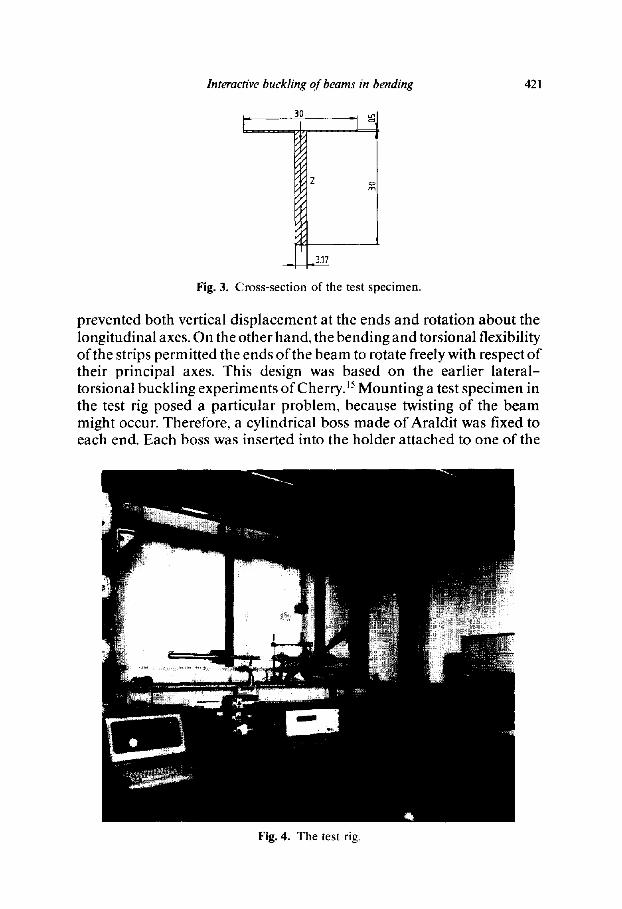
Figure 4 shows the main features of the test rig. The beam was simply supported by suspending it from two thin strips: its in-plane rigidity
W
Fig. 2. The T-beam as used in the experiments.
Interactive buckling of beams in bending 421
30 1 I° z
317
Fig. 3. Cross-section of the test specimen.
prevented both vertical d isp lacement at the ends and rotat ion about the longitudinal axes. On the other hand, the bending and torsional flexibility of the strips permit ted the ends o f the beam to rotate freely with respect o f their principal axes. This design was based on the earlier lateral- torsional buckl ing experiments of Cherry. ~5 Moun t ing a test specimen in the test rig posed a part icular problem, because twisting of the beam might occur. Therefore, a cylindrical boss made of Araldit was fixed to each end. Each boss was inserted into the holder at tached to one of the
Fig. 4. The test rig.
422 C M. Menken, W. J. Groot, G. A. J. Stallenberg
suspension strips. The jaws of the holder were tightened by turning a tapered nut. A lever was attached to each nut in order to apply the bending moment. A simple dead-loading device was used, the consequence being that descending equilibrium paths could not be followed during the experiments. Lateral deflections of the specimen were prevented from becoming too large by means of a hold-up.
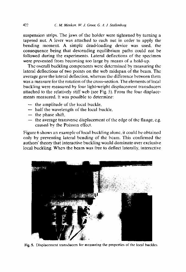
The overall buckling components were determined by measuring the lateral deflections of two points on the web midspan of the beam. The average gave the lateral deflection, whereas the difference between them was a measure for the rotation of the cross-section. The elements of local buckling were measured by four light-weight displacement transducers attached to the relatively stiff web (see Fig. 5). From the four displace- ments measured, it was possible to determine:
the amplitude of the local buckle, half the wavelength of the local buckle,
- - the phase shift, the average transverse displacement of the edge of the flange, e.g. caused by the Poisson effect.
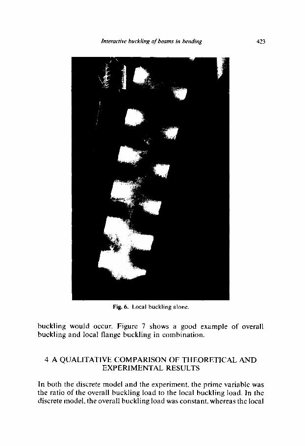
Figure 6 shows an example of local buckling alone, it could be obtained only by preventing lateral bending of the beam. This confirmed the authors' theory that interactive buckling would dominate over exclusive local buckling. When the beam was free to deflect laterally, interactive
Fig. 5. Displacement transducers for measuring the properties of the local buckles.
Interactive buckling of beams in bending 423
Fig. 6. Local buckling alone.
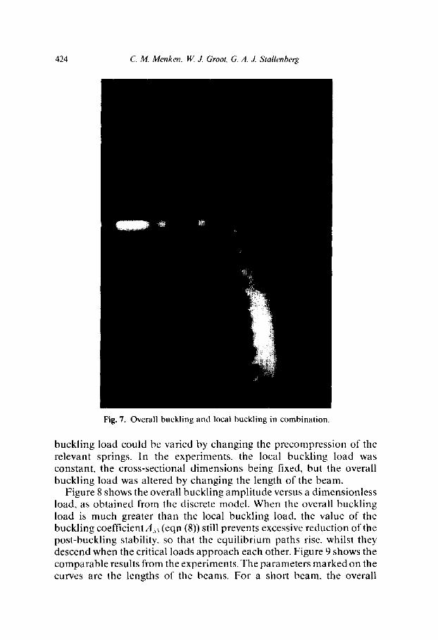
buckling would occur. Figure 7 shows a good example of overall buckling and local flange buckling in combination.
4 A QUALITATIVE COMPARISON OF THEORETICAL AND EXPERIMENTAL RESULTS
In both the discrete model and the experiment, the prime variable was the ratio of the overall buckling load to the local buckling load. In the discrete model, the overall buckling load was constant, whereas the local
424 C. M. Menken, W. J. Groot, G. A. J. Stallenberg
Fig. 7. Overall buckling and local buckling in combination.
buckling load could be varied by changing the precompression of the relevant springs. In the experiments, the local buckling load was constant, the cross-sectional dimensions being fixed, but the overall buckling load was altered by changing the length of the beam.
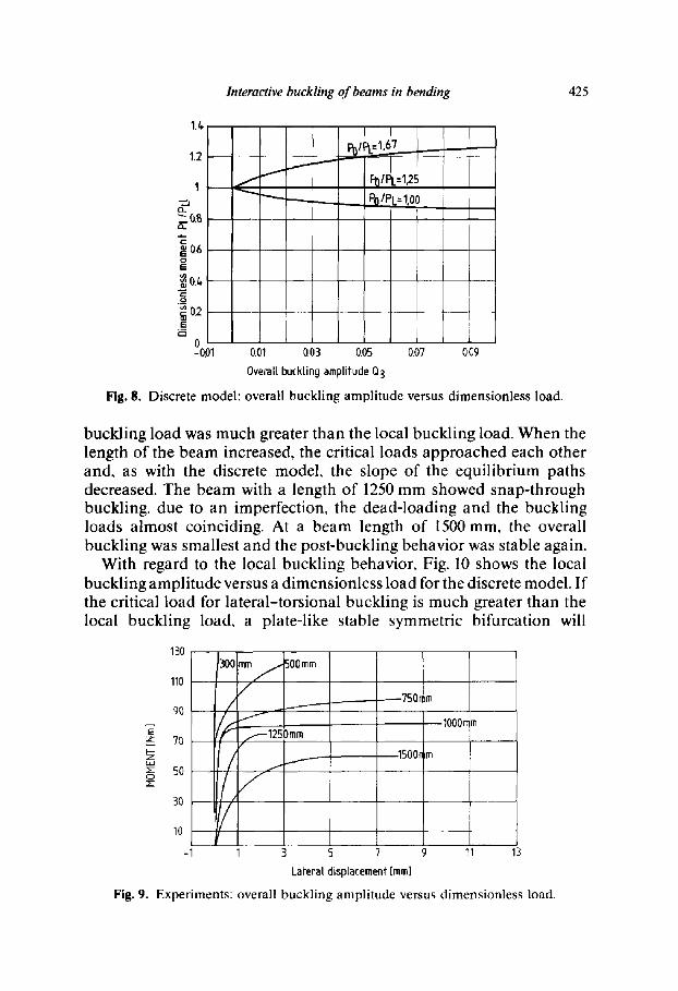
Figure 8 shows the overall buckling amplitude versus a dimensionless load, as obtained from the discrete model. When the overall buckling load is much greater than the local buckling load, the value of the buckling coefficient A33 (eqn (8)) still prevents excessive reduction of the post-buckling stability, so that the equilibrium paths rise, whilst they descend when the critical loads approach each other. Figure 9 shows the comparable results from the experiments. The parameters marked on the curves are the lengths of the beams. For a short beam, the overall
Interactive buckling of beams in bending 425
1.L,
1.2
I
r,, ~0.8
~ Q6 o E
._,5 ~ 02 H
0 -0.01
/ ~ ~-.---...,___ , PO IPL= 1,00
0.01 003 0.05
Overall buckting amp[ifude Q3
0.07 0.09
Fig. 8. Discrete model: overall buckling amplitude versus dimensionless load.
buckling load was much greater than the local buckling load. When the length of the beam increased, the critical loads approached each other and, as with the discrete model, the slope of the equilibrium paths decreased. The beam with a length of 1250 mm showed snap-through buckling, due to an imperfection, the dead-loading and the buckling loads almost coinciding. At a beam length of 1500 mm, the overall buckling was smallest and the post-buckling behavior was stable again.
With regard to the local buckling behavior, Fig. 10 shows the local buckling amplitude versus a dimensionless load for the discrete model. If the critical load for lateral-torsional buckling is much greater than the local buckling load, a plate-like stable symmetric bifurcation will
Z
Z o
130 300 500mm
110 m m f /
9O / ~
70 f.---1250mm
5o
3O
10
-1
~7501 m
1000n m
1500n m
1 3 5 7 9 11 13
Laferal displacement [mm]
Fig. 9. Experiments: overall buckling amplitude versus dimensionless load.

426 C. M. Menken, W. J. Groot, G. A. J. Stallenberg
~.,-J
E.
I=
IE rm
1L,
1.2
1
0.8
0.6 ~ - - ~ l
0.6
0.2
00.2
' '167
%~--too I 4
-0.1 0 Local buckling amplitude Q5
J 0.1 0.2
Fig. 10. Discrete model: local buckling amplitude versus dimensionless load.
dominate. When the buckling loads approach each other, the slope of the post-buckling equilibrium path decreases. The comparable results obtained from the experiment are shown in Fig. 11.
For the shortest beam, the distance between the overall and local buckling loads is greatest and, again, the plate-like stable post-buckling behavior is apparent. While most equilibrium paths show a rather smooth transition from the unbuckled to the buckled state (which can be ascribed to imperfections), the local buckle in the longest beam (1500mm) appears rather suddenly. In this case, overall buckling precedes local buckling, the latter being caused by a secondary bifurcation.
E z I.-- z
o
120
100
80
60
40
2O
0 0
+ OOmm J
-12 50 mm
. /
/ / t
~00 mm
- 1000 mm
~%00mm
750ram
0.2 06 0.6 08
Local buckling amplitude [ram]
Fig. 11. Experiments: local buckling amplitude versus dimensionless load.
Interactive buckling of beams in bending 427
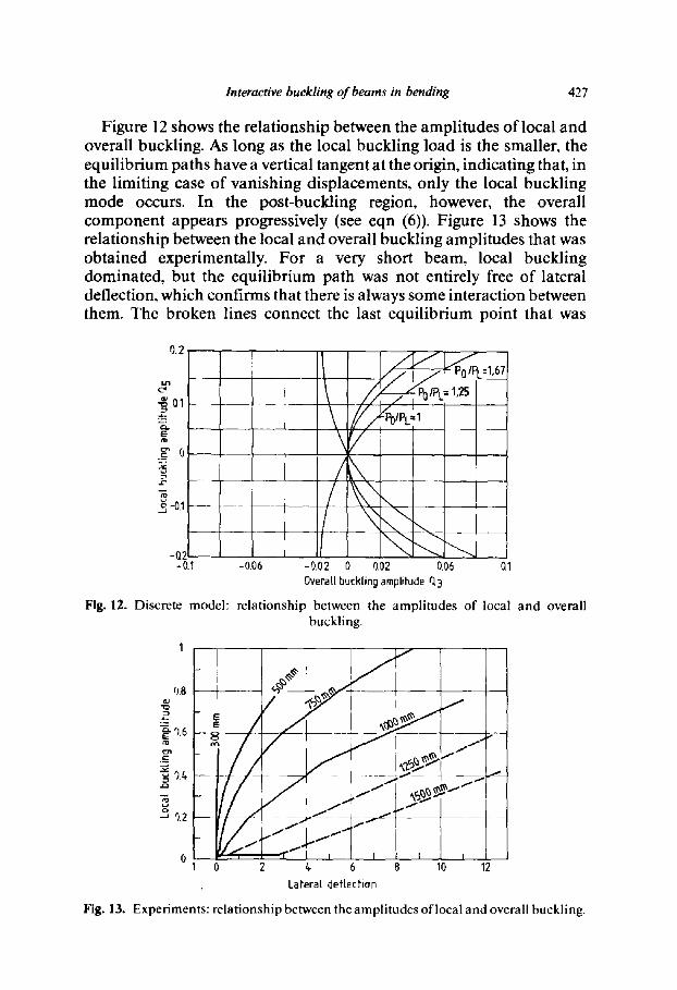
Figure 12 shows the relationship between the amplitudes of local and overall buckling. As long as the local buckling load is the smaller, the equilibrium paths have a vertical tangent at the origin, indicating that, in the limiting case of vanishing displacements, only the local buckling mode occurs. In the post-buckling region, however, the overall component appears progressively (see eqn (6)). Figure 13 shows the relationship between the local and overall buckling amplitudes that was obtained experimentally. For a very short beam, local buckling dominated, but the equilibrium path was not entirely free of lateral deflection, which confirms that there is always some interaction between them. The broken lines connect the last equilibrium point that was
0.2
@
_ o
~j -0.1
-Q21 -0.1 -0.06 0.1
~ = 1,25
\Y
-0.02 0 0.02 0.06 Overall buckling amplitude ri3
Fig. 12. Discrete model: relationship between the amplitudes of local and overall buckling.
O.B
"~0.6
~ ?.2
L
I
/
/
f..1-" Cj.--Y
r i i i
/
2 /~ 6 8 10 12 Lateral deflection
Fig. 13. Experiments: relationship between the amplitudes of local and overall buckling.
428 C. M. Menken. W. J. Groot, G. A. J. Stallenberg
observed while increasing the load, with the equilibrium point pertaining to the situation where buckling was arrested by the hold-up and, thus, indicates snap-through.
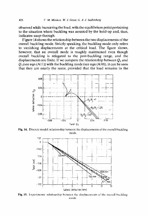
Figure 14 shows the relationship between the two displacements of the overall buckling mode. Strictly speaking, the buckling mode only refers to vanishing displacements at the critical load. The figure shows, however, that an overall mode is roughly maintained even though overall buckling is relegated to the post-buckling range, and the displacements are finite. If we compare the relationship between Q m and Q3 (see eqn (A11)) with the buckling mode (see eqn (AI0)), it can be seen that they are nearly the same, provided that the load remains in the
0.08
0.04.
- 0.0
-0.08
i -
i
i -Q08 -0.0~
J- m
\ PoIPL 1
PO/P~ 1 ,671~
O.OL 0.08 Twist Q1
Fig. 14. Discrete model: relationship between the displacements of the overall buckling mode.
riO1
0
-9.02
-').04
g -o.o6
- 0.08
-0.1
F i g . 1 5 .
-9.32 1 3 3 5 7 9 13 13
Laterat defleOi0n [mm]
Experiments: relationship between the displacements of the overall buckling mode.

Interactive buckling of beams in bending 429
vicinity of the overall buckling loads. The experiments shown in Fig. 15 confirm this behavior.
5 CONCLUSIONS
From an analysis of the simple discrete model, and from the preliminary experiments, it can be concluded that:
- - interactive lateral-torsional buckling belongs to the class of parabolic umbilic catastrophes, according to the discrete model studied;
- - there is a good qualitative agreement between the results obtained from the discrete model and those obtained from the experiments;
- - theoretically, interactive buckling will always occur when the local buckling load is smaller than the overall buckling load;
- - both the shape of the equilibrium paths in the post-buckling region and the continuation of a buckling mode at finite deflections suggest that the asymptotic approach to the analysis of buckling behavior may have a relatively wide range of applications for interactive lateral-torsional buckling.
A C K N O W L E D G E M E N T
This work was supported by research grants from The Netherlands Technology Foundat ion (STW).
REFERENCES
1. Neut, A. van der, The interaction of local buckling and column failure of thin-walled compression members. Proc. 12th Int. Congr. Theor. and Appl. Mech., Springer Verlag, Berlin, 1969, pp. 389-99.
2. Thompson, J. M. T. & Hunt, G. W., Elastic Instability Phenomena, John Wiley and Sons, Chichester, 1984.
3. Koiter, W. T. & Pignataro, M., A general theory for the interaction between local and overall buckling of stiffened panels. Delft University of Technology, Report WTHD-83, 1976.
4. Byskov, E. & Hutchinson, J. W.~ Mode interaction in axially stiffened cylindrical shells. AIAA Journal 15(7) (1977) 941-8.
5. Sridharan, S. & Aii, M. A., An improved interactive buckling analysis of thin-walled columns having doubly symmetric sections. Int. JournalofSolids and Structure. 22(4) (1987) 429-43.
6. Mollmann, H. & Goltermann, P., Interactive buckling in thin-walled beams. Int. J. Solids and Structures, 25(7) (1989) 715-49.
430 C. M. Menken, W. J. Groot, G. A. J. Stallenberg
7. Davies, J. M. & Thomasson, P. O., Local and overall buckling of light gage members. In Instability and Plastic Collapse of Steel Structures, ed. L. J. Morris. Granada Publishing, London, 1983, pp. 479-92.
8. Benito, R., Static and dynamic buckling of plate assemblies. Thesis submitted in partial fulfillment of the requirements of DSc degree of the Washington University of St. Louis, 1983.
9. Sridharan, S. & Benito, R., Static and dynamic interactive buckling. Journal of Engng. Mech.. ASCE. l l0( l ) (1984) 49-65.
10. Erp, G. M. van, Advanced buckling analysis of beams with arbitrary cross sections. PhD Thesis, Eindhoven University of Technology, May 1989.
l l. Erp, G. M. van & Menken, C. M., The spline finite strip method in the buckling analysis of thin-walled structures. Communications in Applied Numerical Methods, 6(6) (1990) 477-84.
12. Koiter, W. T., Elastic stability and post buckling behaviour. In Nonlinear Problems, ed. R. E. Langer, University of Wisconsin Press, Madison. WI, 1963.
13. Budiansky, B. & Hutchinson, J. W., Buckling: progress and challenge. In Trends in Solid Mechanics, Proceedings of the symposium dedicated to the 65th birthday of W. T. Koiter. Delft University Press, Delft, 1979, 93-116.
14. Hunt, G. W. & Williams, K. A. J., Closed form and asymptotic solutions for an interactive buckling model. J. Mech. Phys. Solids, 32(4) (1984) 101-18.
15. Cherry, S., The stability of beams with buckled compression flanges. Structural Engineer. 38(9) (1960) 277-85.
A P P E N D I X
The potential energy of the discrete model
The model is composed of linear elastic springs, together with rigid links and bars. It was assumed that during deformation all springs remained parallel to the original axis of the beam. The overall lateral-torsional buckling and vertical deflection are represented by the rotations, Q~, Q3 and Q2, respectively. Local buckling may cause a shortening of the original neutral axis, Q4. The compression of the spring simulating the web behavior, UA, and the displacements of the spring-link assemblies simulating the flange behavior, uB and uc, are expressed in the overall rotations. The authors used a description in Euler angles to obtain these expressions, the rotation vector Q3 remaining along OA and the sequence of rotations being Q2, Q3, QI. The right-hand displacements of the springs are:
//A ----- Q 4 - - 2asinQ2
uB = Q4 + as in Q2 - bcos Q2 sin Q3
Uc = Q4 + asin Q2 + bcos Q2 sin Q3

Interactive buckling of beams in bending 43 !
The d isplacement of the vertical load is:
Up = /(cos Qt cos Q3sin Q2 - sin Q1 sin Q3)
Local (flange) buckl ing is s imulated by means of spring-link assemblies. The springs having a stiffness o f k are precompressed over a distance u0 by means of the links. If the external load causes a compress ion smaller than u0, the stiffness of each assembly will remain E. However, if the compress ion exceeds the precompression, the links will buckle and the springs become in series, so that a smaller overall stiffness is produced.
The local buckl ing is represented by Q5 and Q6. If local buckl ing occurs, the full compress ion of the precompressed springs becomes:
Uk = u0 + 2d(1 - cos Qi) with i = 5, 6
In this case, the compress ion of the springs having a stiffness E will become:
uzB = uB - 2d(1 - cos Qs)
uEc = Uc -- 2d(1 - cos Q6)
The expression for the potential energy now becomes:
v ( o l , O2, O3, 04, Q5, Q6) = ~stOll 2 + ~EUA1 :
+ ~E{UB -- 2d(1 - cos Qs)} 2 + ~_E{uc - 2d(1 - cos Q6)} 2
_ - kC -- Pup (A1)
Expansion of the potential energy expression around the fundamental state
The fundamenta l state is represented by the deflection Q2 = QV. The authors assumed a l inear elastic behavior prior to buckling: QV << 1. The relevant potential energy expression is:
V ( Q ~ ) = {. 6 a 2 E ( Q F ) : + {" 2 k u o - PIQ~
Stationarity with respect to Q~ gives the fundamenta l path:
P1 - h ( A 2 )
3
The potential energy increment, caused by displacements relative to the fundamenta l path, can be obta ined from eqn (AI) by splitting Q2 into:
Q: = QV + q2
432 C. M. Menken, W. J. Groot, G. A. J. Stallenberg
where q2 represents the incremental vertical deflection. The following assumptions are made:
- - the cross-section is slender: b 2 << h 2 (A3)
- - the incremental deflection is very small: q2 << 1 (A4)
- - the wavelength of the local buckle is of the same order of magnitude as the flange width:
d = 0(b)
- - the precompression of the relevant springs is relatively small:
u0 << d (A5)
- - the additional compression of these springs is of the same order of magnitude as the displacements of the flange tips:
(A6) dO~ = 0(bO3)anddO6 2 = 0(bQ3)
From eqns (A3) and (A6), it appears that:
bdQaQ~ << h 2
bdQ3Q26 << h 2
Successively, the trigonometric terms can be expanded about the fundamental state, the potential energy of the fundamental state is subtracted, and the aforementioned assumptions and the equilibrium equation for the fundamental state are utilized.
The resulting fourth order potential energy expression is:
2 t b2EQ4 V(Q,, q2, Q3, Q4, Qs, Qr) = ~ StQ~ + ~ h2Eq~ + b-EQ3 + ~ .
+ ~EQ~-adE(Q~ + Q~)((Pl~EE + q2 )
+ bdE(Q~ - Qr)Q3 - dE(Q~ + Q6)Q4 + kuod(Q~ + Q{)
+ ~d2(E + k)(Q4 + Q4) + PIQ,Q3 (A7)
The critical loads
The critical loads can be obtained by making the quadratic part o f the potential energy stationary. This results in the fol lowing stability matrix:

Interactive buckling of beams in bending 433
S, 0 PI
0 ]h2E 0
Pl 0 2b2E
0 0 0
0 0 0
0 0 0
0 0 0
0 0 0
3E 0 0
Pl 0 2kuo - ~ 0
0 0 0 0 P!
0 2kuo -
This gives the overall buckling load:
po = b
Q,
q2
Q3
Q4
o ] 0
0
0
Q5 0
Q6] o , _1
(A8)
together with two identical local buckling loads of magnitude:
2kuoh (Ag) PL-- l
The overall buckling mode contains two non-zero parameters, Qt and Q3, where the relationship between them is:
P°I Q3 (A10) Q' = - s ,
Adaptation of the model and confirmation of some assumptions
Since the post-buckling stiffness of flat plates is about half the original stiffness, depending on the boundary conditions, the discrete model has been adapted to it by taking k = E. If the critical loads are available (see eqns (A8) and (A9)) the magnitude of the pre-buckling deflection can be checked when the overall buckling load is attained:
/ ( 2b2E)S , (QV)~,= e,, = .¢ (~h2E)2
Since both the lateral stiffness (2b2E) and the torsional stiffness (St) are assumed to be small when compared with the vertical stiffness (~ h2E), the pre-buckling deflection is indeed small. The pre-buckling deflection at the local critical load is:
3/1o - h
434 C. M. Menken, W. J. Groot, G. A, J. Stallenberg
and since the precompression u0 is assumed to be small, this pre- buckling deflection will also be small.
The fact that a plate-like post-buckling behavior of the flanges has been combined with a nearly neutral overall post-buckling behavior, implies that the former will be dominant. In this case, the Q4-term in the potential energy eqn (A7) can be omitted.
Elimination of passive coordinates
Inspecting the stability matrix shows that there are at least three passive coordinates. 2 They are: the incremental deflection, q2, the shortening, Q4 and one of the parameters of the overall buckling mode. The authors have chosen Q~ as the passive coordinate, leaving Q3 as the amplitude of the overall buckling mode. From the stationarity of the potential energy, the following is obtained:
PI Ov/OQ~ = 0--~Q~ = - ~ Q 3 (All)
d + Ov/OQ2 = O--~ q2 = - 6a
d Ov/OQ4 = O--~Q4 = ~(Q~ + Q26)
It can be seen that only local buckling can give rise to increments in the deflection and shortening.