Embed Size (px)
Citation preview

Visual Neuroscience
Interactions of Prosthetic and Natural Vision in AnimalsWith Local Retinal Degeneration
Henri Lorach,1,2 Xin Lei,3 Ludwig Galambos,3 Theodore Kamins,3 Keith Mathieson,4
Roopa Dalal,2 Philip Huie,1,2 James Harris,3 and Daniel Palanker1,2
1Hansen Experimental Physics Laboratory, Stanford University, Stanford, California, United States2Department of Ophthalmology, Stanford University, Stanford, California, United States3Department of Electrical Engineering, Stanford University, Stanford, California, United States4Institute of Photonics, University of Strathclyde, Glasgow, Scotland, United Kingdom
Correspondence: Henri Lorach,HEPL, 452 Lomita Mall, 94305 Stan-ford, CA, USA;[email protected].
Submitted: June 18, 2015Accepted: October 16, 2015
Citation: Lorach H, Lei X, Galambos L,et al. Interactions of prosthetic andnatural vision in animals with localretinal degeneration. Invest Ophthal-
mol Vis Sci. 2015;56:7444–7450.DOI:10.1167/iovs.15-17521
PURPOSE. Prosthetic restoration of partial sensory loss leads to interactions between artificialand natural inputs. Ideally, the rehabilitation should allow perceptual fusion of the twomodalities. Here we studied the interactions between normal and prosthetic vision in a rodentmodel of local retinal degeneration.
METHODS. Implantation of a photovoltaic array in the subretinal space of normally sighted ratsinduced local degeneration of the photoreceptors above the chip, and the inner retinalneurons in this area were electrically stimulated by the photovoltaic implant powered bynear-infrared (NIR) light. We studied prosthetic and natural visually evoked potentials (VEP) inresponse to simultaneous stimulation by NIR and visible light patterns.
RESULTS. We demonstrate that electrical and natural VEPs summed linearly in the visual cortex,and both responses decreased under brighter ambient light. Responses to visible light flashesincreased over 3 orders of magnitude of contrast (flash/background), while for electricalstimulation the contrast range was limited to 1 order of magnitude. The maximum amplitudeof the prosthetic VEP was three times lower than the maximum response to a visible flashover the same area on the retina.
CONCLUSIONS. Ambient light affects prosthetic responses, albeit much less than responses tovisible stimuli. Prosthetic representation of contrast in the visual scene can be encoded, to alimited extent, by the appropriately calibrated stimulus intensity, which also depends on theambient light conditions. Such calibration will be important for patients combining centralprosthetic vision with natural peripheral sight, such as in age-related macular degeneration.
Keywords: prosthetics, VEP, AMD, rehabilitation
Sensory disorders such as loss of vision or hearing are amongthe most debilitating medical conditions, with devastating
impact on physical and social interactions. Even a partialsensory loss, as in the case of age-related macular degeneration(AMD), can have dramatic consequences on patients’ well-being, with high social cost. In this disease, the central part ofthe visual field, which mediates high-acuity vision, is lost due toeither a local invasion of choroidal blood vessels into the retina(wet form) or atrophy of the retinal pigment epithelium and asubsequent loss of photoreceptors (dry form). Althoughpatients suffering from the wet form benefit from anti-VEGF(vascular endothelial growth factor) treatments, the dry formaccounting for the majority of patients remains untreatable.
One of the potential strategies for vision rehabilitation inthese patients is the implantation of retinal prostheses.Epiretinal implants aim at stimulating the ganglion cells,1 andsubretinal and suprachoroidal implants stimulate primarilybipolar cells2,3 to restore some level of visual perception.Several of these prosthetic approaches are being actively testedin patients blinded by retinitis pigmentosa (RP).4–9 With bothtypes of retinal implants, patients recover some light percep-tion, shape recognition, and orientation capabilities, providingan important proof of principle that degenerated retina is
capable of transmitting patterns of electrical activation to thebrain, which is capable of interpreting these signals aspatterned visual percepts. Due to their limited spatialresolution and functional benefits, these systems have beenimplanted so far only in patients blinded by RP. However, thetechnological advances in electrode density and stimulationefficiency open the door to high-resolution restoration of sight,which could match and even exceed the acuity of theremaining peripheral vision in AMD patients.10 In that case,understanding of the interactions between prosthetic signalsand normal peripheral vision becomes important. Encouragingfindings with cochlear prostheses demonstrated patients’ability to simultaneously utilize their remaining natural hearingat low frequencies and prosthetic stimulation at high frequen-cies, increasing their acoustic bandwidth and improving speechrecognition.11,12
Here, we describe the interaction of prosthetic and normalvisual signals in rats with local retinal degeneration mimickingthe central scotoma in patients with AMD. Cortical potentials inresponse to simultaneous visual and electrical stimulation ofthe retina reveal similarities, differences, and interactionsbetween prosthetic and natural vision.
Copyright 2015 The Association for Research in Vision and Ophthalmology, Inc.
iovs.arvojournals.org j ISSN: 1552-5783 7444
Downloaded From: http://iovs.arvojournals.org/pdfaccess.ashx?url=/data/Journals/IOVS/934655/ on 12/01/2015
MATERIALS AND METHODS
Implant Fabrication
Photovoltaic arrays were manufactured on silicon-on-insulatorwafers using an eight-mask lithographic process, as describedpreviously.13 To produce anodic-first pulses of electric current,the n-doped and p-doped regions in the diodes were reversedcompared to the previous description. Indeed, anodic-firstpulses elicit network-mediated responses of ganglion cells withthresholds three to four times lower than cathodic-first pulses.14
Photovoltaic arrays consisted of 1-mm-diameter and 30-lm-thickstructures (Fig. 1A) composed of 140-lm pixels, separated by 5-lm-wide trenches (Fig. 1B). Each pixel contained two photodi-odes (Figs. 1B, 3) connected in series between the active (Fig.1B, 1) and return (Figs. 1B, 2) electrodes.
Implantation Procedure
A total of nine Long Evans rats (Charles Rivers Farm,Wilmington, MA, USA) were used in this study. Animals wereoperated at 40 days. The subretinal implantation techniquewas similar to the one previously reported by our group.10,15
Animals were anesthetized with a mixture of ketamine (75mg/kg) and xylazine (5 mg/kg) injected intramuscularly. A1.5-mm incision was made through the sclera and choroid 1.5mm posterior to the limbus; the retina was lifted with aninjection of saline solution, and the implant was inserted intothe subretinal space. The sclera and conjunctiva were suturedwith nylon 10-0, and topical antibiotic (bacitracin/polymyxinB) was applied on the eye postoperatively. The anatomicalintegration of the device in the subretinal space wasevaluated by OCT (HRA2-Spectralis; Heidelberg Engineering,Heidelberg, Germany) in periodic examinations beginning 1week after surgery. All animals were used in accordance withthe Association for Research in Vision and OphthalmologyStatement Regarding the Use of Animals in Ophthalmic andVision Research after approval from the Stanford UniversityAnimal Institutional Review Board.
Histology
One year after implantation, eyes (n¼ 3) were enucleated andfixed in 1.25% or 2.5% glutaraldehyde, 1% paraformaldehyde
fixative prepared in 0.1 M sodium cacodylate buffer with 5 mMcalcium chloride and 5% sucrose for 24 hours at roomtemperature. Lenses were removed and eyes were trimmedto a block size and postfixed in 2% aqueous osmium tetroxidefor 2 hours at room temperature. Tissue was then dehydratedin graded alcohol, infiltrated with propylene oxide and epoxy
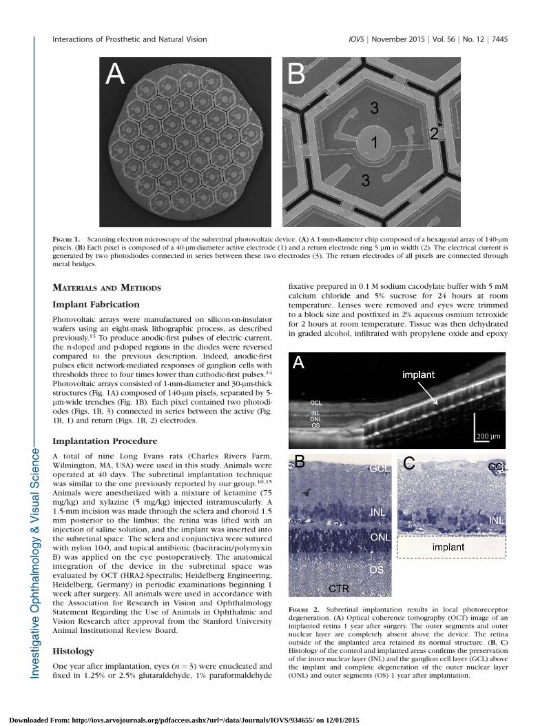
FIGURE 1. Scanning electron microscopy of the subretinal photovoltaic device. (A) A 1-mm-diameter chip composed of a hexagonal array of 140-lmpixels. (B) Each pixel is composed of a 40-lm-diameter active electrode (1) and a return electrode ring 5 lm in width (2). The electrical current isgenerated by two photodiodes connected in series between these two electrodes (3). The return electrodes of all pixels are connected throughmetal bridges.
FIGURE 2. Subretinal implantation results in local photoreceptordegeneration. (A) Optical coherence tomography (OCT) image of animplanted retina 1 year after surgery. The outer segments and outernuclear layer are completely absent above the device. The retinaoutside of the implanted area retained its normal structure. (B, C)Histology of the control and implanted areas confirms the preservationof the inner nuclear layer (INL) and the ganglion cell layer (GCL) abovethe implant and complete degeneration of the outer nuclear layer(ONL) and outer segments (OS) 1 year after implantation.
Interactions of Prosthetic and Natural Vision IOVS j November 2015 j Vol. 56 j No. 12 j 7445
Downloaded From: http://iovs.arvojournals.org/pdfaccess.ashx?url=/data/Journals/IOVS/934655/ on 12/01/2015
(Araldite/Embed; EMS, Hatfield, PA, USA), embedded in pureepoxy, and polymerized at 608C for 24 hours. Thin sections (1lm) were stained with 0.5% toluidine blue, and slides wereexamined under a light microscope.
Implantation of the Cortical Electrodes
Three transcranial screw electrodes (00 3 1/4 stainless steel,part FF00CE250; Morris, Southbridge, MA, USA) were implant-ed similarly to a previously published technique16 and securedin place with cyanoacrylate glue and dental acrylic. Theseelectrodes penetrate the skull but do not enter the brain tissue.Two electrodes were placed over the visual cortex, one in eachhemisphere, 4 mm lateral from the midline, 6 mm caudal to thebregma. One reference electrode was implanted 2 mm right ofthe midline and 2 mm anterior to the bregma. Nose and tailneedle electrodes served as reference and ground, respectively.Recordings started 2 months after the subretinal implantationto ensure the complete loss of photoreceptor light-mediatedsignals above the chip.
Anesthesia During Recordings
Rats were anesthetized with a mixture of ketamine (37.5 mg/kg) and xylazine (2.5 mg/kg) injected intramuscularly. Thefollowing steps were taken to ensure steady anesthesia.Spontaneous eye movements and respiratory patterns werechecked periodically; supplementary injection of half theinitial dose was administered every 40 minutes, or as needed,and recording sessions were limited to 120 minutes persession. A heating pad was used to maintain the bodytemperature at 37.5 6 0.58C.
Retinal Stimulation
The stimulation system included a single-mode pigtailed near-infrared (NIR) (915 nm) laser and a visible light (532 nm)laser coupled into a 1-mm-diameter optical fiber. Thecollimated output beam illuminated a Digital Micro-mirrorDevice (DMD; DLP Light Commander; LOGIC PD, Carlsbad,CA, USA) to form the patterns. The optical system wasmounted on a slit lamp (Zeiss SL-120; Carl Zeiss, Thornwood,NY, USA) to allow direct observation of the patterns on theretina with a charge-coupled device camera (acA1300-60gmNIR; Basler, Ahrensburg, Germany). Following the pupildilation, the cornea was covered with a viscoelastic gel and acoverslip to cancel the optical power of the cornealcurvature and ensure stimulus focalization. The coverslipwas taped to the animal’s head to maintain a stable contactwith the cornea during the entire recording session. Ocularretraction was required in some cases to help align theimplant with the beam. The position of the light pattern onthe implant was continuously monitored and adjusted ifnecessary by the experimenter. For each animal, twodifferent recording paradigms were performed. In one ofthese, NIR alone was presented over the entire implant, andthe irradiance was varied from 0.06 to 4 mW/mm2 with 10-ms pulse duration. In another session, visible and NIR weresimultaneously presented in a multifocal paradigm with aconstant NIR irradiance of 4 mW/mm2, while visible lightirradiance was varied from 15 nW/mm2 to 3 lW/mm2. Everyrecording was performed with two different ambient whitelight conditions: dim (0.8–1.1 nW/mm2) and bright (90–115nW/mm2), corresponding to 2.4 and 250 nW, respectively,transmitted through a 3.5-mm iris, matching the pupil size ofa dilated rat eye.
Visually Evoked Potential Recording and Analysis
Visually evoked potential (VEP) signals were recorded withan Espion E2 system (Diagnosys, Inc., Lowell, MA, USA) at 1-kHz sampling rate using 0.5- to 500-Hz bandpass filter, andaveraged over 250 trials for each experiment. Corticalthresholds were determined for the stimuli covering thewhole implant (1 mm in diameter) using 10-ms pulses, anddefined as the minimum light intensity for which the VEPamplitude during the first 100 ms after the pulse exceededsix times the noise level. This noise level was defined as thestandard deviation of the signal during the 50 ms precedingthe stimulus. Modulation of the VEP amplitude by lightintensity was measured using 10-ms pulses, and normalizedto the response at 1 mW/mm2.
Multifocal Stimulation
The multifocal stimulation paradigm was implemented in amanner similar to that reported previously17,18 but using abinary random noise instead of the m-sequence. Light patterns(random checkerboards, 1-mm-square size) were generated bycustom software (Psycholtoolbox, Matlab; The Mathworks,Natick, MA, USA). For each visible light intensity, the stimulusconsisted of 1000 random checkerboards containing 1-mmsquares, alternating every 500 ms and illuminated by a single10-ms light pulse during each phase (4 mW/mm2 for NIR andvariable irradiance for visible light). After acquisition, themultifocal analysis was performed offline by a custom routine(Matlab; The Mathworks). The stimulation artifact measured onthe cornea was used to synchronize the stimulation patternwith the recording. For each square of the checkerboard, thefirst order of the VEP signal was obtained by adding the trials inwhich this square was ON and subtracting the trials in which it
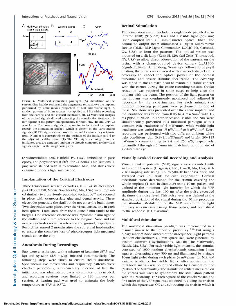
FIGURE 3. Multifocal stimulation paradigm. (A) Stimulation of thesurrounding healthy retina and the degenerate retina above the implantperformed by simultaneous projection of NIR and visible light. Arandom pattern of 1-mm squares was applied at 2 Hz while recordingfrom the corneal and the cortical electrodes. (B, C) Multifocal analysisof the evoked signals allowed extracting the contribution from each 1-mm square of the pattern independently for both ERG (B) and VEP (C)waveforms. The corneal signal corresponding to the area of the implantreveals the stimulation artifact, which is absent in the surroundingsignals. (D) VEP signals shown over the retinal locations they originatefrom. Number 3 corresponds to the position of the implant and 4 tothe adjacent healthy retina. (E) The VEP signals coming from theimplanted area are extracted and can be directly compared to the visualsignals elicited in the neighboring area.
Interactions of Prosthetic and Natural Vision IOVS j November 2015 j Vol. 56 j No. 12 j 7446
Downloaded From: http://iovs.arvojournals.org/pdfaccess.ashx?url=/data/Journals/IOVS/934655/ on 12/01/2015
was OFF (i.e., correlating the recording with the stimulus). For
two neighboring squares of the checkerboard, the second-
order signal was obtained by adding trials in which the two
squares were in the same state (either ON or OFF) and
subtracting the trials in which the two squares were in
opposition. The second-order amplitude reveals the deviation
from linear interaction between the two contributions.
Fitting and Prosthetic Contrast Mapping
Dependence of the VEP amplitude on contrast of the visible
light flash and on NIR irradiance was fitted by sigmoidal curves
f ðxÞ ¼ 11þðx0=xÞa . For normalization of the prosthetic stimula-
tion to the ambient light background, the scaling factor kbetween the two conditions (dim and bright backgrounds) was
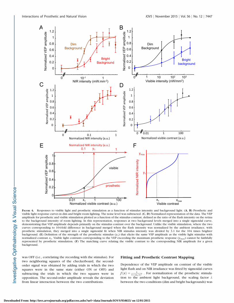
FIGURE 4. Responses to visible light and prosthetic stimulation as a function of stimulus intensity and background light. (A, B) Prosthetic andvisible light response curves in dim and bright room lighting. The noise level was subtracted. (C, D) Normalized representation of the data. The VEPamplitude for prosthetic and visible stimulation plotted as a function of the stimulus contrast, defined as the ratio of the flash intensity on the retinato the background intensity of room lighting. In this representation, responses at two background levels merged into a single sigmoidal curve,demonstrating that VEP amplitude depends primarily on the stimulus contrast over the background. Unlike the visible stimulation, where the twocurves corresponding to 104-fold difference in background merged when the flash intensity was normalized by the ambient irradiance, withprosthetic stimulation, they merged into a single sigmoidal fit when NIR stimulus intensity was divided by 3.1 for the 104 times brighterbackground. (E) Definition of the strength of the prosthetic stimulus (y1) that elicits the same VEP amplitude as the visible light stimulus withnormalized contrast x1. Visible light contrasts corresponding to the VEP exceeding the maximum prosthetic response (ymax) cannot be faithfullyrepresented by prosthetic stimulation. (F) The matching curve relating the visible contrast to the corresponding NIR amplitude for a givenbackground.
Interactions of Prosthetic and Natural Vision IOVS j November 2015 j Vol. 56 j No. 12 j 7447
Downloaded From: http://iovs.arvojournals.org/pdfaccess.ashx?url=/data/Journals/IOVS/934655/ on 12/01/2015
obtained by minimizing the deviation of the combined data[Xdim;Xbright / k] [Ydim;Ybright] from a single sigmoidal fit.
For each visible light contrast value (x), the correspondingNIR contrast (y) producing the same VEP amplitude wasdefined, up to the maximum of prosthetic response (ymax).Mathematically, if f(x) and g(y) are the normalized VEPresponses for visible and prosthetic stimulation, the matchingcurve is defined by y ¼ h(x) ¼ g�1 � f(x).
For (f) and (g) being sigmoidal curves in the form f ðxÞ ¼1
1þðx0=xÞa and gðyÞ ¼ b
1þðy0=yÞb, the hðxÞ ¼ y0
½ðb�1Þþbðx0=xÞa �1=bis
defined up to: xmax ¼ x0½ b1�b�1=a.
RESULTS
Subretinal Implantations and Local Degeneration
of Photoreceptors
Long Evans (wild-type) rats were implanted subretinally with 1-mm-diameter silicon arrays (see Methods; Fig. 1A andpreviously published study13). Each pixel contained twophotodiodes connected in series between an active, 40-lm-diameter electrode and a 5-lm-wide ring return electrodesurrounding the pixel (Fig. 1B). These pixels convert light intoelectrical current flowing through the tissue between thestimulating and return electrodes. Near-infrared (915 nm)illumination was used to activate the photovoltaic pixels whileavoiding any visual response in rats.15,19
The subretinal implantation triggered the loss of photore-ceptor outer segments above the implant within a month and asubsequent loss of the outer nuclear layer after 3 months20
(Fig. 2A). The inner retina, however, remained preserved even1 year after implantation (Figs. 2B, 2C). Therefore, thesubretinal implantation itself created a local model of retinaldegeneration with a normal retina outside of the implantedarea and a scotoma above the prosthesis.
Equivalent Brightness of Prosthetic Percept andDependence on Background Illumination
In this animal model of local retinal degeneration, we assessedprosthetic and natural vision by recording from the primaryvisual cortex via transcranial screw electrodes (see Methods).Prosthetic or visually evoked potentials in response to invisibleNIR (915 nm) or visible (532 nm) light were recordedseparately or simultaneously.
To assess the relative amplitude of prosthetic and naturalvisual responses, we used a multifocal protocol for probing therelative contributions and linearity of summation of the twocortical signals (previously published study17 and Fig. 3A).Both NIR and visible light patterns are simultaneously appliedover the entire retinal area. However, due to the local loss ofphotoreceptors, the implanted area receives only electricalstimulation (see Methods). Although the square area of thecheckerboard exceeds the circular implant by approximately20%, degeneration of the photoreceptors up to 100 lm awayfrom the edge of the implant reduces the overlap withphotosensitive area to a few percent. We demonstratedpreviously that projection of a square pattern of similar sizewith visible light over the implant did not elicit detectablecortical responses.10 Based on this observation, we disregardedthe mismatch between the shapes of the implant and thecheckerboard. The multifocal analysis allows extracting theVEP originating from each square of the checkerboard andcalculating the relative contributions of the prosthetic andnormal visual inputs to the cortical signal (Fig. 3C). Simulta-neous measurements of the electrical signal on the corneausing ERG electrode reveal the stimulation artifact from theimplant (Fig. 3B, location 3). Such multifocal protocol isessential to avoid scattering effects in the retina and extract thecortical contribution of each 1-mm square in the pattern forcomparison with the implant-mediated responses (Figs. 3D,3E).
To evaluate the strength of the prosthetic percepts relativeto normal visual response, we modulated the visible lightintensity from 0 to 3 lW/mm2 and the NIR irradiance from 60lW/mm2 to 4 mW/mm2 in both dim and bright room lightconditions (see Methods). In both cases, the VEP responsesincreased with increasing light intensities, and both responsecurves shifted to higher irradiances at brighter backgroundconditions (Figs. 4A, 4B). This indicates that adaptation of thesurrounding retina to background illumination affects theprosthetic cortical response originating in the scotoma.
This adaptation to background illumination can also beinterpreted as a modulation of the contrast of the stimulus.Indeed, expressing the flash brightness in units of contrast bynormalizing the stimulus irradiance to the background levelconverged the two curves from Figures 4A and 4B into a singlecontinuous VEP response curve fitted by a sigmoidal function(Figs. 4C, 4D; Methods). The 104-fold increase in backgroundillumination required a 104-fold increase in intensity of thevisible light stimulus to produce the same cortical response.However, with the prosthetic response the ratio was verydifferent: Only a 3.1-fold increase in the NIR irradianceproduced the same cortical response at 104-fold brighterbackground (see Methods). Multiplication of the NIR irradiance
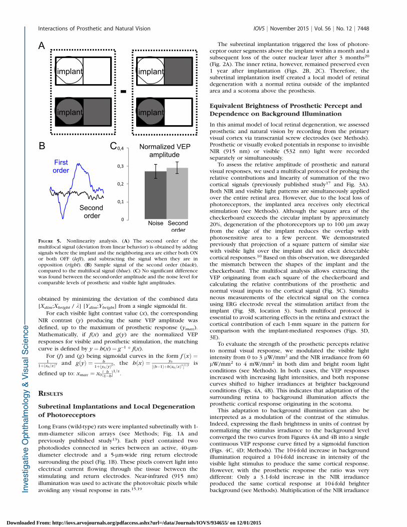
FIGURE 5. Nonlinearity analysis. (A) The second order of themultifocal signal (deviation from linear behavior) is obtained by addingsignals where the implant and the neighboring area are either both ONor both OFF (left), and subtracting the signal when they are inopposition (right). (B) Sample signal of the second order (black),compared to the multifocal signal (blue). (C) No significant differencewas found between the second-order amplitude and the noise level forcomparable levels of prosthetic and visible light amplitudes.
Interactions of Prosthetic and Natural Vision IOVS j November 2015 j Vol. 56 j No. 12 j 7448
Downloaded From: http://iovs.arvojournals.org/pdfaccess.ashx?url=/data/Journals/IOVS/934655/ on 12/01/2015
by this factor resulted in fusion of the sigmoidal curvescorresponding to the dim and bright background (Fig. 4A).
Measuring these contrast sensitivity curves for both naturaland prosthetic signals provides guidance for adjusting thecontrast in the NIR image to achieve perceptual coherence incase of partial photoreceptor degeneration. To elicit VEP of thesame amplitude with normal and prosthetic stimulation, weestablished the correspondence between the contrasts of thenormal and prosthetic stimuli (Fig. 4E). In this procedure, thevalues of the visible light contrast (x1) are converted into thecorresponding NIR irradiance (y1) producing the same VEPamplitude for a given background (Fig. 4F). However, sinceprosthetic response saturates at a lower VEP level than naturalresponse, contrast exceeding a certain value (xmax) cannot befaithfully represented by prosthetic stimulation, and thecontrast transformation curve plateaus above that value. Thiscurve defines the NIR irradiance, which elicits the same VEPamplitude as the visible light flash at the same ambient lightbackground.
Linearity of Summation Between Normal andProsthetic Vision
To check the degree of linearity in the summation of thenormal and prosthetic vision we analyzed the second momentof the multifocal signal (see Methods). Subtracting the corticalsignals recorded in trials when prosthetic and normal stimuliare not simultaneous from the trials when they are simulta-neous yields the first-order deviation from linear prediction(Fig. 5A and Methods). This deviation was not significantlydifferent from the noise (Figs. 5B, 5C), indicating that normaland prosthetic contributions to the retinal signals sum linearlyin the visual cortex.
DISCUSSION
This study demonstrates that prosthetic and natural visualsignals are transmitted to the brain simultaneously withoutinhibiting each other. Coexistence of the normal and prosthet-ic vision is critical for restoration of sight in patients withpartial loss of vision. We found that the natural visually evokedsignals sum linearly with prosthetic response, withoutdetrimental interactions. Interestingly, ambient backgroundlighting affects the prosthetic response, although to a muchlesser extent than with visible light stimulation, and therefore itshould be considered for proper encoding of the prostheticimage.
Decreasing the checkerboard pitch below the implant sizein the multifocal stimulation paradigm should allow character-ization of the summation properties and integration ofprosthetic and normal vision on a finer spatial scale. In rats,arrays with 70-lm pixels provided grating visual acuitymatching the pixel pitch,10 so resolution of a single pixelmight be possible. However, since signal-to-noise ratiodecreases with the pitch of the checkerboard pattern, thesemeasurements will likely require much longer integration.
In terms of the amplitude, the maximum strength of thecortical signals elicited by the subretinal prosthesis wasapproximately three times lower than the saturation levelelicited by the visible flash applied over the same area on theretina. Several mechanisms might be responsible for thisdifference. First, unlike what occurs with optical stimulation,only a fraction (approximately half) of the retinal ganglion cells(RGCs) respond to subretinal electrical stimulation, as mea-sured in vitro.21 Second, the maximum number of spikeselicited in RGCs by electrical stimulation is approximately halfthat elicited by visible flashes.10 Finally, indiscriminate
stimulation of ON and OFF pathways could lead to partialcancellation of these signals in the brain.
One of the important questions for proper encoding ofprosthetic stimulation is the relationship between the corticalpotentials and the actual perceptual brightness. In humanpatients the VEP signal scales linearly with the logarithm of thecontrast,22 and extrapolation of the VEP amplitude to the noiselevel closely matches the psychophysical perceptual threshold.Therefore, comparable amplitudes of the prosthetic andnatural visual responses and their linear summation indicatethat the contrast correspondence between the two modalitiescan be established.
The photovoltaic retinal prosthesis can operate in patientswith remaining peripheral vision as an augmented realitysystem: Video goggles transparent to visible light overlie theNIR images projected onto the subretinal implant.23 Sincepatients will use them indoors and outside, ambient light levelswill vary over several orders of magnitude. Our resultsdemonstrate that prosthetic responses are affected by theambient light similarly to normal vision (although we were notable to measure the absolute retinal irradiance from diffuseambient light) and therefore prosthetic representation of theobjects should depend not only on their contrast in the originalscene but also on the ambient light the patient is exposed to.Since the perceptual brightness (judged by the amplitude ofVEP) of prosthetic stimulation is lower than the maximumbrightness of the visible light by a factor of 3, prostheticstimulation can represent only a part of the visible lightresponse range.
Clinical trials of this system will enable comparingperception of prosthetic and natural stimulation and therebyrefine the algorithms of image processing for prosthetic vision.Such calibration of the contrast adjustment algorithm accord-ing to the background lighting and contrast of the visual scenemight need to be performed for every patient at different levelsof background light. In addition to lenses correcting therefractive errors in patients, the goggles could include anadjustable neutral density filter for visible light to tune theambient illumination of the retina to match prostheticpercepts.
Coexistence of prosthetic and natural vision, combinedwith high resolution of photovoltaic implants10 and their easeof implantation, opens the door to application of thistechnology for restoration of central vision in AMD patients.
Acknowledgments
We thank G. Goetz for technical help with the image projectionsystem, M.F. Marmor and S. Picaud for stimulating discussions andencouragement, and J. Liao for access to the VEP recording setup.
Supported by the National Institutes of Health (NIH) (Grant R01-EY-018608), the Department of Defense (Grant W/81XWH-15-1-0009), NIH Clinical and Translational Science Awards (Award UL1RR025744), and the Stanford Spectrum fund. KM was supportedby an SU2P fellowship as part of an Research Councils UK ScienceBridges award. HL was supported by the Foundation Voir etEntendre (Paris) and Pixium Vision.
Disclosure: H. Lorach, Pixium Vision (F); X. Lei, None; L.Galambos, None; T. Kamins, None; K. Mathieson, None; R.Dalal, None; P. Huie, None; J. Harris, None; D. Palanker,Pixium Vision (C), P
References
1. Humayun MS, de Juan E Jr, Dagnelie G, Greenberg RJ, PropstRH, Phillips DH. Visual perception elicited by electricalstimulation of retina in blind humans. Arch Ophthalmol.1996;114:40–46.
Interactions of Prosthetic and Natural Vision IOVS j November 2015 j Vol. 56 j No. 12 j 7449
Downloaded From: http://iovs.arvojournals.org/pdfaccess.ashx?url=/data/Journals/IOVS/934655/ on 12/01/2015

2. Chow AY, Pardue MT, Chow VY, et al. Implantation of siliconchip microphotodiode arrays into the cat subretinal space.IEEE Trans Neural Syst Rehabil Eng. 2001;9:86–95.
3. Zrenner E. Can subretinal microphotodiodes successfullyreplace degenerated photoreceptors? Vision Res. 1999;39:2555–2567.
4. Chow AY, Bittner AK, Pardue MT. The artificial silicon retina inretinitis pigmentosa patients (an American OphthalmologicalAssociation thesis). Trans Am Ophthalmol Soc. 2010;108:120–154.
5. Hornig R, Zehnder T, Velikay-Parel M, Laube T, Feucht M,Richard G. The IMI retinal implant system. In: Humayun M,Weiland J, Chader G, Greenbaum E, eds. Artificial Sight. NewYork: Springer; 2008:111–128.
6. Humayun MS, Dorn JD, da Cruz L, et al. Interim results fromthe international trial of Second Sight’s visual prosthesis.Ophthalmology. 2012;119:779–788.
7. Stingl K, Bartz-Schmidt KU, Besch D, et al. Subretinal visualimplant alpha IMS–clinical trial interim report. Vision Res.2015;111:149–160.
8. Ayton LN, Blamey PJ, Guymer RH, et al. First-in-human trial of anovel suprachoroidal retinal prosthesis. PLoS One. 2014;9:e115239.
9. Fujikado T, Kamei M, Sakaguchi H, et al. Testing of semi-chronically implanted retinal prosthesis by suprachoroidal-transretinal stimulation in patients with retinitis pigmentosa.Invest Ophthalmol Vis Sci. 2011;52:4726–4733.
10. Lorach H, Goetz G, Smith R, et al. Photovoltaic restoration ofsight with high visual acuity. Nat Med. 2015;21:476–482.
11. Gantz BJ, Turner CW. Combining acoustic and electricalhearing. Laryngoscope. 2003;113:1726–1730.
12. Dorman MF, Spahr AJ, Loizou PC, Dana CJ, Schmidt JS.Acoustic simulations of combined electric and acoustichearing (EAS). Ear Hear. 2005;26:371–380.
13. Wang L, Mathieson K, Kamins TI, et al. Photovoltaic retinalprosthesis: implant fabrication and performance. J Neural
Eng. 2012;9:046014.
14. Boinagrov D, Pangratz-Fuehrer S, Goetz G, Palanker D.Selectivity of direct and network-mediated stimulation of theretinal ganglion cells with epi-, sub- and intraretinal elec-trodes. J Neural Eng. 2014;11:026008.
15. Mandel Y, Goetz G, Lavinsky D, et al. Cortical responseselicited by photovoltaic subretinal prostheses exhibit similar-ities to visually evoked potentials. Nat Commun. 2013;4:1980.
16. You Y, Klistorner A, Thie J, Graham S. Latency delay of visualevoked potential is a real measurement of demyelination in arat model of optic neuritis. Invest Ophthalmol Vis Sci. 2011;52:6911–6918.
17. Sutter EE. Imaging visual function with the multifocal m-sequence technique. Vision Res. 2001;41:1241–1255.
18. Hood D, Bach M, Brigell M, et al. ISCEV standard for clinicalmultifocal electroretinography (mfERG) (2011 edition). Doc
Ophthalmol. 2012;124:1–13.
19. Lorach H, Goetz G, Mandel Y, et al. Performance ofphotovoltaic arrays in-vivo and characteristics of prostheticvision in animals with retinal degeneration. Vision Res. 2014;111:142–148.
20. Lorach H, Kung J, Beier C, et al. Development of animalmodels of local retinal degeneration. Invest Ophthalmol Vis
Sci. 2015;56:4644–4652.
21. Mathieson K, Loudin J, Goetz G, et al. Photovoltaic retinalprosthesis with high pixel density. Nat Photonics. 2012;6:391–397.
22. Campbell FW, Maffei L. Electrophysiological evidence for theexistence of orientation and size detectors in the human visualsystem. J Physiol. 1970;207:635–652.
23. Goetz GA, Mandel Y, Manivanh R, Palanker DV, Cizmar T.Holographic display system for restoration of sight to theblind. J Neural Eng. 2013;10:056021.
Interactions of Prosthetic and Natural Vision IOVS j November 2015 j Vol. 56 j No. 12 j 7450
Downloaded From: http://iovs.arvojournals.org/pdfaccess.ashx?url=/data/Journals/IOVS/934655/ on 12/01/2015