Embed Size (px)
Citation preview

Document oom,DW$WT ROOM 36-412Research Laboratory of ec' -ro i
Massachusetts Institute of Tochnology
INTERACTION OF MODES IN MAGNETRON OSCILLATORS
R. R. MOATS
LO1 0o
TECHNICAL REPORT NO. 171
JUNE 25, 1951
RESEARCH LABORATORY OF ELECTRONICSMASSACHUSETTS INSTITUTE OF TECHNOLOGY
CAMBRIDGE, MASSACHUSETTS
Om
of

The research reported in this document was made possiblethrough support extended the Massachusetts Institute of Tech-nology, Research Laboratory of Electronics, jointly by the ArmySignal Corps, the Navy Department (Office of Naval Research)and the Air Force (Air Materiel Command), under Signal CorpsContract No. DA36-039 sc-100, Project No. 8-102B-0; Depart-ment of the Army Project No. 3-99-10-022.

MASSACHUSETTS INSTITUTE OF TECHNOLOGY
RESEARCH LABORATORY OF ELECTRONICS
Technical Report No. 171 June 25, 1951
INTERACTION OF MODES IN MAGNETRON OSCILLATORS
R. R. Moats
This report is essentially the same as a doctoral thesis
in the Department of Electrical Engineering, M. I. T.
Abstract
The magnetron is described in terms of its properties as a feedback oscillator, to
show that nonlinear circuit theory may be applied in discussing mode interactions. The
interaction of modes in a nonlinear feedback oscillator with two resonances is con-
sidered, and it is shown that when large-amplitude oscillation associated with one mode
of resonance is present, this oscillation tends to suppress oscillation associated with
the other mode. These theoretical observations are supported directly by measurement
of the loading effect of an oscillating mode in a magnetron upon small-amplitude
externally-supplied oscillations in another mode. They are also supported indirectly
by observation of the performance of several different types of magnetrons.


INTERACTION OF MODES IN MAGNETRON OSCILLATORS
I. Introduction
The Problem
One of the most perplexing problems in magnetron work has been the "moding"
problem. This problem arises because of the multiplicity of resonances in the anode
structure, and because it is possible for the electron stream to support oscillation in
any one of several modes of resonance. Also associated with the moding problem is the
fact that under certain circumstances, the oscillating mode may fail altogether, and this
event may or may not be followed by the starting of another mode of oscillation. Causes
for mode failure are often obscure, especially when such failure is accompanied by the
starting of oscillation in another mode.
In order to achieve proper operation of a magnetron, it is necessary to establish
stable large-amplitude oscillation in only one of these modes. Some of the most wide-
spread applications of magnetrons require microsecond-pulse operation. In magnetrons
designed for such operation, it is necessary to establish oscillation in the desired mode
positively and quickly, and to maintain it stably for the duration of the pulse. In magne-
trons designed for c-w operation, quick starting is usually not a requirement, but sta-
bility is as important as in pulse magnetrons. Thus, the problems to be discussed here
are of two kinds. First, the mode selection problem involves the establishing of oscil-
lation in the desired mode positively and quickly in pulse magnetrons. Second, the mode
stability problem involves keeping the established oscillation stable, in either pulse or
c-w magnetrons. Either of these two problems may be concerned with the avoidance of
oscillation in unwanted modes.
The significance of the mode stability problem is emphasized by the fact that one of
the limits on high power in magnetrons is the maximum power for which the desired
mode of oscillation is stable.
The general form of the solution of the wave equation for the electric field in the
interaction space, assumed to be an infinitely long cylinder, is: E exp(jpo) Z (kr), where
Zp indicates a linear combination of Bessel and Neumann function of the pth order, and
k is the propagation constant such that k = 2r/k, where X is the free-space wavelength
at the frequency considered. To match the solution to the boundary conditions at the
inside periphery of the interaction space, Hartree (ref. 16) resolved the r-f electric
field into Fourier components in space, and these components are called Hartree har-
monics. In an anode structure where all N cavities are alike, the values of p for which
r-f field components are actually present in the n t h mode are given by p = n + AN, where
A = 0, +1, ±2, etc. If the cavities alternate between two sizes, as in the rising-sun
anode structure, p = n + N/2.
The field configurations described above lead to N possible modes. The actual
pattern around the anode is described by
-1-
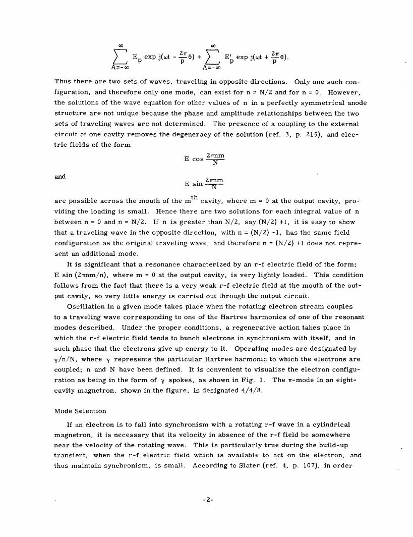
Ep exp j(wt - 2r0) + E exp j(wt 2 rrEE exp j(wt + r).A=- oo A= - o e
Thus there are two sets of waves, traveling in opposite directions. Only one such con-
figuration, and therefore only one mode, can exist for n = N/2 and for n = 0. However,
the solutions of the wave equation for other values of n in a perfectly symmetrical anode
structure are not unique because the phase and amplitude relationships between the two
sets of traveling waves are not determined. The presence of a coupling to the external
circuit at one cavity removes the degeneracy of the solution (ref. 3, p. 215), and elec-
tric fields of the form
2rrnmE cos
andE sin
are possible across the mouth of the mth cavity, where m = 0 at the output cavity, pro-
viding the loading is small. Hence there are two solutions for each integral value of n
between n = 0 and n = N/2. If n is greater than N/2, say (N/2) +1, it is easy to show
that a traveling wave in the opposite direction, with n = (N/2) -1, has the same field
configuration as the original traveling wave, and therefore n = (N/2) +1 does not repre-
sent an additional mode.
It is significant that a resonance characterized by an r-f electric field of the form:
E sin (2rnm/n), where m = 0 at the output cavity, is very lightly loaded. This condition
follows from the fact that there is a very weak r-f electric field at the mouth of the out-
put cavity, so very little energy is carried out through the output circuit.
Oscillation in a given mode takes place when the rotating electron stream couples
to a traveling wave corresponding to one of the Hartree harmonics of one of the resonant
modes described. Under the proper conditions, a regenerative action takes place in
which the r-f electric field tends to bunch electrons in synchronism with itself, and in
such phase that the electrons give up energy to it. Operating modes are designated by
y/n/N, where y represents the particular Hartree harmonic to which the electrons are
coupled; n and N have been defined. It is convenient to visualize the electron configu-
ration as being in the form of y spokes, as shown in Fig. 1. The r-mode in an eight-
cavity magnetron, shown in the figure, is designated 4/4/8.
Mode Selection
If an electron is to fall into synchronism with a rotating r-f wave in a cylindrical
magnetron, it is necessary that its velocity in absence of the r-f field be somewhere
near the velocity of the rotating wave. This is particularly true during the build-up
transient, when the r-f electric field which is available to act on the electron, and
thus maintain synchronism, is small. According to Slater (ref. 4, p. 107), in order
-2-

500 1000 1500 2000
MAGNETIC FIELD (GAUSS)
Fig. 1 Fig. 2
Electron paths in oscillating Hartree diagram for 718 EYmagnetron, showing "spokes. " magnetron. Threshold vol-Coordinates are rotating in tages: (1) = 3/3/8 mode,synchronism with r-f wave. (2) = 4/4/8 mode (r-mode),Arrows indicate direction of (3) = 5/3/8 mode.r-f electric field (ref. 4).
that an electron in a circular orbit at radius r should have a velocity v, the following
conditions must be met
E=v(B - m )e r
(E = electric field intensity, B = magnetic flux density, m = mass, and e = charge of the
electron; units are rationalized mks). From this he estimates the d-c potential differ-
ence between anode and cathode for synchronism between electrons and r-f traveling
waves. Hartree (ref. 16) has developed an expression for the minimum d-c anode vol-
tage for an electron to reach the anode in the presence of an infinitesimal r-f rotating
wave. Hartree's expression for voltage, like Slater's, is a function of the velocity of
the r-f rotating wave, of anode and cathode diameters, and of magnetic flux density.
Hartree's criterion provides better agreement with observed magnetron operation than
Slater's, although they are qualitatively similar in most respects.
In Fig. 2, the Hartree voltages for three modes in a typical eight-resonator magne-
tron are shown as functions of magnetic field. Also shown is the d-c cut-off curve, at
which it is possible for electrons leaving the cathode with zero velocity to reach the
anode in the presence of constant fields (ref. 3, p. 177).
Hartree (ref. 16, also ref. 1, p. 340) was apparently the first to point out the pos-
sible rotating wave components associated with any given mode in a multisegment reso-
nant anode structure, and that it is possible for the electron stream to become coupled,
under different conditions, to different components corresponding to the same mode of
resonance.
Bunemann (ref. 1, Ch. 6, p. 253) uses another approach to establish a necessary
condition for oscillation. He assumed first the existence of the Brillouin steady state,
which represents a solution to the electron motion problem. In such a solution, the
radial current is zero, and the electrons are all moving in concentric circles. This is
-3-

also referred to as a single-stream solution of the electron-motion problem. (Twiss
(ref. 31) has shown that a single-stream solution is impossible in the presence of a
Maxwellian distribution of emission velocities, and that a double-stream solution is
always possible under such circumstances. The single-stream solution may be
approached as a limit as emission velocities approach zero. The question of how the
electrons in a magnetron could ever fall into the single-stream solution was also raised.)
Under certain conditions of voltage and magnetic field, a perturbation of the single-
stream steady state corresponding to an r-f rotating wave may cause the space charge
to become unstable, and spokes (cf. Fig. 1) will build up, thus initiating oscillation.
When such a voltage, corresponding to regeneration in a particular mode, is reached,
it is called the instability voltage for that mode.
Instability voltages have been computed (ref. 22), and it is found that for values of
y of four or less, the instability voltages are comparable with threshold voltages and
represent plausible standards for minimum starting voltages in terms of observed
starting voltages. For larger values of y, the instability voltages become further
removed from both the threshold voltages and observed starting voltages. It is neces-
sary to conclude that the instability voltage criterion is, in general, not applicable to
actual magnetrons. On the other hand, threshold voltages are never in very great dis-
agreement with observed starting voltages.
Fletcher and Rieke (ref. 14; ref. 1, Ch. 8) have pointed out the importance of pulse
modulator characteristics, especially the rate of rise of the voltage pulse applied to the
magnetron, and the pulser's output impedance. They have shown how a pulse may rise
so rapidly that it passes through the range in which the desired mode can start before
oscillation in that mode can build up appreciably, and into a region where an undesired
mode, or no mode at all, can start. If oscillation in the desired mode could have built
up more quickly, or if the rise in voltage had been slower, oscillation would have caused
direct current to flow, and the flow of current would have held the voltage down to a
value where oscillation in the desired mode could have persisted. On the other hand, it
is pointed out that if the open-circuit voltage of the pulser falls within the range in which
the desired mode can start, or if the rate of rise of the pulse can be reduced, it should
be possible to eliminate misfiring (that is, failure to start in the desired mode).
The problem of competition between modes, which occurs when the anode voltage of
the magnetron is rapidly raised from zero to a value at which oscillation in either of
two modes could be supported, is discussed by Rieke (ref. 1, Ch. 8). The process of
one mode gaining ascendancy over the other and eventually suppressing it is described
from a nonlinear circuit point of view. In particular, he points out that when the ampli-
tudes of oscillation in both modes are so large that nonlinear effects are important, it
is necessary that the rate of build-up in either mode be affected more by the amplitude
of oscillations in the other mode than by its own amplitude. Such a condition is neces-
sary in order that mode selection be definite on any particular pulse. This condition
does not preclude uncertainty of selection as between successive pulses of the same
-4-

amplitude.
Here, Rieke has described the assumption that the rate of build-up of one mode is
affected more by the amplitude of the other mode than by its own amplitude, as being
open to question. It is evident that it must be valid for all, or at least nearly all, of the
observed cases, because of the definiteness of mode selection on any particular pulse.
In a later section, theoretical reasons tending to confirm Rieke's assumption will be
advanced.
Mode Stability and Mode Changes
Mode selection has been discussed as a transient problem; here, mode stability, a
steady-state problem, will be considered. The only kind of magnetron in which a
strictly steady-state analysis is applicable is the c-w magnetron. In many stability
problems in pulse magnetrons, the time required for appreciable changes in operating
conditions is very long in terms of r-f cycles, and the steady-state analysis is entirely
acceptable. In many other pulse magnetrons, a borderline condition between a mode-
stability problem and a mode-change problem is encountered. This borderline situation
is considered, although some of the fundamental principles previously mentioned apply.
It should be emphasized that starting criteria may not necessarily be expected to
apply for a given mode, once large-amplitude oscillation has been established in another
mode. For example, the Hartree starting criterion, i. e. the threshold voltage, is no
longer as applicable as it was before oscillation started. This criterion specifies the
anode potential at which an electron can just reach the anode in the presence of an
infinitesimal r-f wave rotating with a given velocity, and in the presence of a given
magnetic field, for any particular magnetron, assuming zero emission velocity. In the
presence of large-amplitude oscillation in one mode, another r-f rotating wave of small
amplitude can have little effect upon whether an electron reaches the anode. It is sig-
nificant that the threshold voltage represents a necessary but not sufficient condition
for oscillation.
Many of those who have worked with magnetrons have accepted starting criteria,
which were intended to apply only to the given mode in the absence of others, as being
equally applicable to the given mode in the presence of large-amplitude oscillation in
another mode. Some of these ideas often seemed to be confirmed when magnetron
design changes were made. An example of such an idea, which became fairly wide-
spread, at least tacitly, is that raising the starting voltage of the next higher-voltage
mode above the rr-mode will necessarily increase the maximum voltage at which the
1r-mode can be operated stably. There are two possible reasons for reaching this con-
clusion. First, the use of straps increased the upper limit of input current and input
voltage for which a magnetron was stable in the w-mode. The straps also increased
the resonant frequency for other modes as compared with the rr-mode, and therefore
increased their respective starting voltages. Hence, the voltage of the Tr-mode
could be raised further above the threshold value without reaching the starting
-5-

voltage for another mode. Some were led to the conclusion that the fundamental
improvement in stability resulted from the separation of threshold voltages. The pre-
sently accepted explanation for the principal cause of the improvement is that the sepa-
ration of the resonant frequencies prevents contamination of the rr-mode r-f pattern
with components of other modes, as discussed previously (ref. 1, Ch. 4). Another
cause of confusion was the application of the expression " moding, " both to improper
starting and to instability of the desired mode. It is reasonable to expect that starting
in the wrong mode becomes more difficult as its range of starting voltages becomes
further removed from the starting range for the desired mode.
Another concept of mode stability based entirely on other possible modes has been
advanced by Copley and Willshaw (ref. 22; ref. 8, p. 1000). They first assume that
both the threshold and the instability voltage criteria must be met before oscillation
takes place. After oscillation is established, the applied voltage may be increased
indefinitely with corresponding increase in power, until the instability voltage for
another mode is reached. At this point oscillation in the original mode ceases, but
oscillation in the second mode will not start unless (or until) the threshold voltage for
the second mode has been reached. Thus it is possible that there will be a range of
anode voltages in which no oscillation will take place. Calculations showed that if the
cathode diameter were increased, the values of threshold voltage decreased while
values of instability voltage increased. Thus, the voltage range between the threshold
voltage of the desired mode (in all cases under discussion by these authors, the rr-mode)
and the instability voltage of the next higher-voltage mode can be increased; since,
according to the theory, the maximum input current is approximately proportional to
this voltage range, to maximize this voltage is to maximize input power. If the increase
in cathode diameter does not reduce efficiency too much, such a procedure should be
expected to lead to greater output power.
The application of this mode-change criterion to actual magnetrons produced agree-
ment with theory in some respects, at least qualitatively. The most significant bit of
agreement was observed when the cathode diameters were increased. This change
actually led to considerable increases in output, as well as input, power.
The latter theory of mode change is based on several assumptions which are very
much open to question. Doubt as to the possible existence of a Brillouin steady state
has been mentioned. Another doubtful point is whether the calculated instability vol-
tages could have any significance when large-amplitude oscillation is already present.
Dunsmuir (ref. 9) has raised a much more fundamental question: whether a lower-
voltage mode, whose conditions for oscillation have already been met in terms of thres-
hold and instability voltages, should necessarily give way to a higher-voltage mode as
soon as the latter's conditions for oscillation are met.
Experimental evidence refutes this mode change criterion, and any other general
criterion based solely, or even primarily, on the unwanted modes. Some of the experi-
mental work reported on in a subsequent section shows clearly a set of mode changes
-6-

depending primarily on conditions in the originally oscillating mode, instead of the mode
into which the change took place; in another test, Tr-mode oscillation is maintained
stably as the applied voltage is raised past both threshold and instability voltages for at
least one other mode, and it stops only when d-c cutoff is reached.
The magnetron improvements which were accomplished by application of the insta-
bility-voltage criterion can be explained otherwise. An increase in cathode radius leads
to more stable operation because of the increased intensity of the r-f electric fieldth
available near the cathode for bunching; the intensity of the latter field for the p order
Hartree harmonic is proportional to r, where r is one of the coordinates of the cylin-
drical system. This effect will be discussed further.
The maximum-current limitation in magnetrons had also been encountered at the
Bell Telephone Laboratories (ref. 18, ref. 1, p. 378). The problem was to design a
magnetron in the 1220-Mc/sec to 1350-Mc/sec range (L-band) for high-power operation.
The maximum current limitation in other L-band magnetrons had been recognized as
being related to the rate of rise of the applied voltage pulse. It was further recognized
that the failure to operate in the T-mode was independent of the presence of other modes.
This problem involves some of the aspects of both mode skip or misfiring and the
kind of stability problem met with in c-w magnetrons and in those with slowly rising
pulses. A quantity, critical current I c was defined as the input current at which there
was first observed a narrowing of the current pulse at the leading edge. It was found
that as the rate of voltage rise became less, I c increased. A maximum value was
approached which could not be exceeded by any further decrease in the rate of voltage
rise.
A systematic experimental study was made to determine the effect of the variation
of design parameters upon Ic. As in the magnetrons reported on by Copley and Willshaw
it was found that stability of the r-mode was increased by increasing the ratio of cathode
radius' to anode radius; it was also found that lighter loading increased Ic . Unfortunately,
each of these changes which might be made to increase I also would decrease electronic
efficiency. The idea of building a magnetron which was very much dependent on a slow
rise of applied voltage was rejected, because this would limit the versatility of the
magnetron more than was considered desirable. As a result of the above considerations
a magnetron was designed with a much larger ratio of cathode radius to anode radius
than previous eight-segment magnetrons.
Problems arising from high rate of voltage rise as compared with the rate of build-
up are more acute in lower frequency magnetrons, such as L-band, as compared with
S-band and higher frequencies. In magnetrons which are equivalent otherwise, but have
different frequencies, the build-up rates per cycle should be the same.
An explanation for this type of combined misfiring and stability problem apparently
depends on the fact that the building up of oscillation causes current to flow from the
pulser, and thus reduces the applied voltage, and also that greater r-f amplitude
increases the voltage range for which electrons can be kept in synchronism with the
-7-

r-f traveling wave. The faster r-f build-up can take place in relation to the rate of rise
of the applied voltage, the greater the chance of stability. There is a continuous tran-
sition from the mode-skip transient problem to the steady-state stability problem.
Some experiments in magnetron design were made at the M. I. T. Radiation
Laboratory for the purpose of making a mode less stable (ref. 15). The test magnetrons
all had K-7 (2J32) anodes, with anode diameter of 13. 6 mm, and cathode diameters of
4, 5, 6, and 8 mm were used. The problem was to discourage oscillation in the 5/3/8
mode which has a slightly lower starting voltage than the rr-mode (4/4/8). Most effi-
cient operation was found using the 4-mm cathode, but the cathode melted at moderate
powers. Operation with 5-mm cathodes (for which the tube was originally designed) was
satisfactory, while operation with 6-mm or 8-mm cathodes led to large areas on the
performance chart where the unwanted mode interfered with operation in the Tr-mode.
Thus, increasing cathode diameter has made the unwanted lower voltage mode more
stable, to the extent that it interferes with Tr-mode operation.
Litton Industries (ref. 21) of San Carlos, California, has altered the design of a
tunable c-w magnetron for the purpose of increasing the maximum current for which
the rr-mode is stable. The approach used here was to increase the perveance (E. E.
Dept. M.I. T.: Applied Electronics, p. 169, Wiley, 1943) of the magnetron considered
as a simple d-c diode. The perveance was increased 20 percent in one magnetron by
increasing the cathode diameter by 10 percent. The maximum input current for Tr-mode
operation was increased 75 percent or more, depending on tuning, with little change in
efficiency. It is also interesting to observe that the increase in I brought about by the
increase in the cathode radius was only 18 percent. A further small increase in per-
veance was made by decreasing the anode radius, and this change of dimension led to
almost no change in I o . The latter change led to a decrease in the upper current limit
in the Tr-mode at the maximum-frequency setting of the tuner, but to an increase by a
factor of about four times at the minimum frequency.
The failure of a mode of oscillation as a result of the failure of the bunching mecha-
nism to maintain synchronism between rotating electrons and the r-f field was implied
by Slater in 1941 (ref. 4). It has been discussed by this writer (ref. 19) and investi-
gated by the General Electric Research Laboratories (ref. 20). The failure of oscilla-
tion is interpreted as being due to the tendency of a high d-c electric field to make the
electrons rotate at a rate higher than that of the r-f traveling wave. These phenomena
will be discussed in detail in the following section.
An attempt has been made recently by Welch and others at the University of Michigan
to establish more definite mode stability criteria, and an estimate has been made of the
space-charge limited current in an oscillating c-w magnetron (ref. 35). This does not
necessarily lead to an adequate criterion for the maximum current associated with
stable Tr-mode oscillation, because space-charge limited current is a function of anode
voltage, and there is yet no adequate theory which leads to a maximum voltage for sta-
bility.
Io is one of the magnetr6n characteristic scale factors. See Ref. 1, Ch. 10.
-8-

II. The Magnetron as a Feedback Oscillator
Energy Conversion in Oscillators
To make it possible to describe properly the characteristics of any particular mode
of oscillation, the magnetron will be considered briefly here in terms of its properties
as a feedback oscillator.
In electronic oscillators in general, there is an active electronic system, which
converts d-c energy into a-c energy, and there is a passive system which is frequency-
sensitive and which controls electron flow or electron motion in the active system in
such a way that the active system can produce a net output great enough to supply energy
for losses and load. In the cylindrical magnetron, electrons tend to travel in more or
less circular paths; if these electrons can be caused to rotate in synchronism with an
r-f traveling wave, and to be bunched in the proper phase to give up energy to the wave,
then energy conversion in the electron stream of the magnetron can take place.
In usual magnetron operation, the initial bunching results from one mechanism, and
bunching is maintained by another. These have been described in some detail by Fisk,
Hagstrum, and Hartman (ref. 3, pp. 189-196), and the fundamentals are reviewed
briefly below.
Upon leaving the cathode with zero velocity, in the presence of nontime-varying
fields (radial electric, axial magnetic field), the electron would start toward the anode,
but its path would be bent by the magnetic field and it would return toward the cathode,
reaching the cathode surface with zero velocity. If there is, in addition, an r-f wave
rotating in the same direction as the electron, then the electron may receive from or
give up energy to the r-f field. If it absorbs energy, it will be driven into the cathode
with a finite velocity, and will be taken out of the system. If it gives up energy to the
system it will return to a point of zero radial velocity in the space between cathode and
anode. Thus it has had work done on it by the d-c electric field, and has done work on
the r-f field. It is now in a position to stay in the system, and under favorable condi-
tions, it may make more such loops toward the anode, giving up energy to the r-f fieldeach time. Ideally when such an electron finally reaches the anode, it will have con-
verted most of the energy put into it by the d-c field into r-f energy. The electrons
emitted in such a phase as to extract energy from the r-f field will be referred to as
unfavorable, and those emitted so as to add energy to the r-f field will be called favor-
able electrons.
In the reference mentioned above (ref. 3, pp. 189-196), the phase-focusing mecha-
nism is also described. Under normal conditions, this mechanism will apply princi-
pally to favorable electrons, with the others removed from the system as they are
driven back into the cathode. When an electron leads the position in the r-f traveling
wave at which the electron would give up the maximum amount of energy to the tangen-
tial component of the r-f field, it is also acted upon by the radial component of the r-ffield. The latter component is directed in such a way that, in combination with the
-9-

axial magnetic field, the electron is accelerated toward the position at which it would
give up maximum energy to the r-f field. On the other hand, a lagging electron is sub-
jected to the action of the opposite r-f radial field, and is likewise accelerated toward
the position where it would give up maximum energy to the tangential r-f field.
Build-Up Process
Small-amplitude phenomena in magnetrons are much less well understood, qualita-
tively, than are large-amplitude phenomena. For this reason a completely satisfactory
explanation of the build-up process is not yet possible. An attempt will be made here
to supply a description of r-f build-up that is plausible from a qualitative point of view.
In the presence of only one r-f rotating wave, and with zero emission velocity, the
rejection of unfavorable electrons should be complete as soon as any coherent r-f wave
is present. In the presence of a Maxwellian distribution of emission velocities, it is to
be expected that the rejection process will be incomplete fbr small r-f amplitude, and
will increase in effectiveness with increasing r-f amplitude. During early stages of
build-up, synchronism of electrons with the r-f wave will not necessarily be maintained
all the way to the anode. In the first place, the average velocity toward the anode is
small, being proportional to the r-f amplitude; in the second place, the effect of the
r-f phase-focusing field may be expected to be small, in general, as compared with
whatever tendency the d-c field, in combination with the magnetic field, may have
toward making the electrons rotate at a velocity other than in synchronism with the r-f
wave. If the velocity of electrons is even approximately equal to that of the r-f wave,
the bunched electrons, starting in the right phase (the unfavorable electrons having been
rejected), should stay in the right phase long enough to lead to a net contribution of
energy by electrons to the r-f wave.
As r-f amplitude increases further, the phase-focusing mechanism becomes
increasingly effective in maintaining synchronism of the electron stream. The ampli-
tude of r-f voltage necessary for effective phase focusing depends on the difference
between the rotational velocity of the r-f wave and that of the electrons in the absence
of the r-f field.
The final stage occurs when both of these bunching mechanisms are complete, and
the electron stream is, to a first approximation, a constant-current generator. Then
the r-f voltage Vrf approaches a limit Vma x as follows
Vrf= Vmax(l - e at).
Some r-f build-up measurements were made by Fletcher and Lee (ref. 32; ref. 1,
pp. 373-376) at the M. I.T. Insulation Research Laboratory. These results are plotted
in Figs. 3 and 4. Figure 4 shows that in the first stage, the build-up process is expo-
nential, and not very sensitive to anode voltage, once the process has started. (The
later starting when anode voltages are lower may be due to the greater delay in
-10-

+15-- t lO'SECS)-
V 4.6
V."5KV V 4. K
- t (0' SECS) --
Fig. 3
R-f build-up in magnetron. (a) Applied voltage. (b) R-f envelopesfor different applied voltages. (c) Anode currents for differentapplied voltages (ref. 32).
reaching threshold voltage on the anode when peak amplitude is less, or to less noise
in the electron stream. ) This stage in Fig. 4 may well be associated with the first
stage, when the electron rejection process is becoming more effective. Above 200 watts
r-f power output, the rate of build-up is more dependent on anode voltage. This may
reasonably be associated with the second stage, when rate of build-up is increasingly
dependent on the effectiveness of the phase-focusing. For still higher levels of output
nower the ciirve tke on the form V = V (1 - e-at)..... - ..... rf max'- -J
indicating that bunching is practically complete.
V=4.6k,, .f While the above explanation appears reasonable, it
V .3kv~-L '' is also evident that there is much room for further/ ,* V4.0kv
/,- .' _ investigation on this subject.
*.V.75k : o . :
o'
. I I I40 60 80
NUMBER OF R-F CYCLES
Fig. 4
Logarithmic plots of thr-f envelopes shown inFig. 3 (ref. 32).
"Strength" of Modes
Reference has been made to competition between
mbdes, especially during build-up, and to the ability of
a mode of oscillation to persist at high current and high
power output. The strength of a mode may be consid-
ered a measure of its ability to persist either against
possible competition from other modes, or against the
destructive effect of excess anode voltage, which would
-11-
-5
T 4v(KV)
2
1
0 +5 +10
10,00C600C4000
20<
1000
i 600i 400
a 200
100
, 60r 4o
20
IC
_ _
&
.
- X - -
--
I I ___ I
I
-

tend to accelerate electrons to a velocity greater than that of the r-f wave. Evidently
the principal factor determining the strength of a mode is simply the effectiveness of
feedback, as might be expected for any feedback oscillator. (No attempt will be made
to take into account the fact that the relative strengths of two modes might not neces-
sarily be the same in the transient case as in steady-state conditions. )
The effectiveness of feedback may be expressed in terms of the loop transmission
in a feedback amplifier. In such an amplifier, gain = 7L/(1 - p3), where = gain without
feedback, and represents the proportion of output signal fed back to the input. In an
oscillator, for steady-state operation, Lp = 1. When Apd is greater than unity, oscilla-
tions are building up. In usual feedback oscillators, p depends on the passive circuit
and is constant. This may be taken to be the case for magnetrons. Then p. is dependent
on amplitude of oscillation, and on loading of the resonant circuit. The feedback ratio,
[3, depends on the geometry of the anode and of the space between cathode and anode. It
is quite important that bunching be effective near the cathode, but it is in this region
that the r-f electric field is weakest, since the magnitude of the r-f radial electric field
is approximately proportional to r, for the pth order Hartree harmonic. Hence, is
quite dependent upon rc/ra, the ratio of cathode radius to anode radius. The dependence
of stability on this ratio was pointed out by Slater in 1941 (ref. 4); he estimated optimum
values of rc/ra as a function of N for r-mode operation, seeking a good compromise
between efficiency and stability.
For a high degree of stability, it is desirable that the feedback signal be large, so
that oscillations will be as insensitive as possible to disturbances. This leads to a high
value of Apd for small signals, resulting in a relatively fast build-up. The effect of such
a condition in terms of mode interactions will be discussed in more detail.
If only one Hartree component is considered in analyzing the magnetron as a feed-
back oscillator, the analogy between the magnetron and a conventional feedback oscil-
lator is quite straightforward. The feedback mechanisms in a magnetron oscillator
with one r-f rotating wave have been discussed. It has been assumed that the traveling
waves corresponding to other Hartree harmonics pass by the electrons so quickly as to
have no net effect. The validity of this assumption is supported by the agreement
between calculated and measured threshold voltages, since threshold voltages are cal-
culated using such an assumption.
Under some circumstances other Hartree harmonics cannot be safely ignored in
considering the feedback process. This is particularly true when the component to
which the electron stream is coupled is of higher order than the lowest order compo-
nent present. It has been pointed out that the intensity of the radial r-f field component
of a pth order Hartree harmonic is approximately proportional to r P . Thus, r-f field
components which are of comparable magnitude near the anode may differ greatly near
the cathode, with the advantage to the lowest-order component. An extreme example
is illustrated in Fig. 5 by the detected r-f radial field pattern picked up by a rotating
probe, displayed on a cathode-ray screen, as a function of angular position of the probe.
-12-
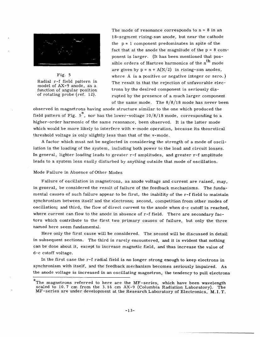
The mode of resonance corresponds to n = 8 in an
18-segment rising-sun anode, but near the cathode
the p = 1 component predominates in spite of the
fact that at the anode the magnitude of the p = 8 com-
ponent is larger. (It has been mentioned that pos-
sible orders of Hartree harmonics of the n t h mode
are given by p = n + A(N/2) in rising-sun anodes,Fig. 5 where A is a positive or negative integer or zero. )
Radial r-f field pattern in The result is that the rejection of unfavorable elec-model of AX-9 anode, as afunction of angular position trons by the desired component is seriously dis-of rotating probe (ref. 12). rupted by the presence of a much larger component
of the same mode. The 8/8/18 mode has never been
observed in magnetrons having anode structure similar to the one which produced the
field pattern of Fig. 5, nor has the lower-voltage 10/8/18 mode, corresponding to a
higher-order harmonic of the same resonance, been observed. It is the latter mode
which would be more likely to interfere with rr-mode operation, because its theoretical
threshold voltage is only slightly less than that of the rr-mode.
A factor which must not be neglected in considering the strength of a mode of oscil-
lation is the loading of the system, including both power to the load and circuit losses.
In general, lighter loading leads to greater r-f amplitudes, and greater r-f amplitude
leads to a system less easily disturbed by anything outside that mode of oscillation.
Mode Failure in Absence of Other Modes
Failure of oscillation in magnetrons, as anode voltage and current are raised, may,
in general, be considered the result of failure of the feedback mechanisms. The funda-
mental causes of such failure appear to be first, the inability of the r-f field to maintain
synchronism between itself and the electrons; second, competition from other modes of
oscillation; and third, the flow of direct current to the anode when d-c cutoff is reached,
where current can flow to the anode in absence of r-f field. There are secondary fac-
tors which contribute to the first two primary causes of failure, but only the three
named here seem fundamental.
Here only the first cause will be considered. The second will be discussed in detail
in subsequent sections. The third is rarely encountered, and it is evident that nothing
can be done about it, except to increase magnetic field, and thus increase the value of
d-c cutoff voltage.
In the first case the r-f radial field is no longer strong enough to keep electrons in
synchronism with itself, and the feedback mechanism becomes seriously impaired. As
the anode voltage is increased in an oscillating magnetron, the tendency to pull electrons
The magnetrons referred to here are the MF-series, which have been wavelengthscaled to 10. 7 cm from the 3. 16 cm AX-9 (Columbia Radiation Laboratory). TheMF-series are under development at the Research Laboratory of Electronics, M. I. T.
-13-
�II�I _j
ahead of synchronous velocity also increases. The electrons now tend to lead the point
in the rotating wave at which maximum energy would be given up, and their effective-
ness becomes diminished. Eventually the combination of excessive acceleration of the
d-c field, combined with the decreased effectiveness of the electrons in building up the
r-f field, leads to failure of oscillations.
The increase in anode voltage also leads to increased amplitude of oscillation and
therefore the phase-focusing action may increase at a rate comparable with or greater
than the increasing tendency of the d-c field to make electrons exceed synchronous
velocity. Another effect of the increased r-f amplitude is that the transit time of an
electron between cathode and anode is shortened. This has the effect of decreasing the
electronic efficiency (detrimental to stability), but it also decreases the time during
which a favorable electron can get out of phase.
Another requirement placed upon the phase-focusing mechanism is to prevent
dispersion of electron spokes, which would otherwise take place as a result of the
mutual repulsion of electrons. Little information is available on how charge density
within the spokes varies with changes in operating conditions. If, at higher power
levels, the density is higher, the debunching effect due to mutual repulsion is stronger.
This effect will increase the tendency toward instability. However, at higher power
levels, greater debunching should be opposed by greater r-f field intensity.
A secondary cause of failure is inadequate emission. In order to get an increase
of r-f amplitude necessary to maintain stability in the face of increased d-c voltage, an
increase in current is necessary. If the cathode cannot supply the necessary current,
the collapse of oscillation then results from deficient phase focusing. The cathode also
produces more subtle effects, since the distribution of electric fields may depend on
whether emission is space-charge limited, and since the emission velocities may also
affect the distribution of electric fields. The relative importance of the various effects
produced by the cathode is not clear. The most obvious of the cathode effects, that is,
the presence of sufficient emission, is evidently inadequate to explain all observed
phenomena, as has been pointed out by Dench, of Raytheon, and reported by Welch of
the University of Michigan (ref. 35, pp. 37-44). For low values of temperature-limited
emission (from an oxide cathode), the maximum anode current for stable Tr-mode oscil-
lation increased with increasing temperature; for higher values of emission, a maximum
was reached, after which there was a slight decrease in maximum current with
increasing temperature.
The fundamental reasons for instability, described above, remain the same in prin-
ciple when there are significant nonuniformities in the magnetron in an axial direction.
It is pointed out by Feldmeier (ref. 1, Ch. 13) that uniformity of magnetic field is neces-
sary because of the large variation in current which can result from small variations in
magnetic field. Rieke and Fletcher (ref. 17; ref. 1, p. 380) suggested a change in the
pole piece design of the 2J39 magnetron which led to a more uniform magnetic field, and
a great increase in stability was achieved. (Experimental work on the 2J39 will be
-14-

described in a later section. ) It seems reasonable to attribute the poor stability of mag-
netrons with nonuniform magnetic fields to the fact that when one portion of the anode is
drawing a large current, another portion (where the magnetic field is stronger) may be
drawing little or none; and when the anode voltage is raised to give the latter portion of
the anode a chance to draw a reasonable amount of current, the electrons in the portion
of the interaction space where magnetic field is weak may well find themselves out of
synchronism, and therefore not contributing their share of energy to the r-f wave. If
the velocity of these unsynchronized electrons in the weak magnetic field is near that
corresponding to another mode, it is not inconceivable that competition will take place,
with the second attempting to build up and suppress the first mode.
Axial nonuniformities in the r-f field are also possible. They are most prevalent in
strapped anodes (ref. 18, p. 17) and in closed-end rising-sun anodes (ref. 1, Ch. 3,
p. 110). The above reasoning suggests that these nonuniformities affect both the sta-
bility and efficiency adversely. For example, it is to be expected that synchronism
between r-f field and electrons will be lost in a region of weak r-f field much more
readily than where the field is strong. The extent of these effects has apparently not
been studied, and there seems to be no evidence to indicate that it is very serious,
especially in strapped magnetrons.
There has been one kind of axial nonuniformity which has been used to improve
operation. It has been found that a slight enlargement of the cathode for a small dis-
tance at each end helped to prevent misfiring without adversely affecting efficiency or
stability to any great extent (ref. 1, Ch. 8, p. 379).
We have indicated that the two principal factors which are most important to stable
operation are axial uniformity (especially magnetic) and the effectiveness of the r-f
feedback. The latter depends principally on the intensity of the r-f electric field and on
its freedom from disturbances by other modes and by components of the desired mode
other than the one to which the electrons are coupled. Disturbance by another mode
may take place when both the wanted and unwanted modes are near each other in fre-
quency, and this may be prevented by adequate separation of mode frequencies. Effec-
tive bunching of electrons by an r-f electric field tends to suppress any tendency of the
electron stream to supply energy to other modes, and this will be discussed in detail.
Unwanted Hartree harmonics of the desired mode ordinarily do not cause trouble in
rr-mode oscillation, with the exception of zero-order component interference in rising-
sun magnetrons (ref. 1, Ch. 3, pp. 98-100). The latter type of interference can be
effectively eliminated by proper choice of magnetic field.
There are two principal means by which the r-f feedback can be made more intense.
The first is to lighten loading. Thus, a given amount of r-f power leads to larger r-f
electric fields, but such a change also leads to lower efficiency, both electronic and in
the r-f circuit. The second means for increasing the r-f feedback is to alter the geo-
metry of the system, especially by increasing r /r a in order to increase the r-f inten-
sity near the cathode. (The latter change was discussed in Sec. I. ) This change also
-15-

leads to lower electronic efficiency. Thus, in these two instances, it is necessary to
sacrifice efficiency in order to gain stability, and magnetron design becomes a compro-
mise.
III. Mode Interactions: Nonlinear Circuit Theory
Nonlinear Triode Oscillator
The fundamental theory on which this section is based was first studied by
van der Pol about thirty years ago (ref. 23 and 24). The earliest theory was for a sim-
ple nonlinear triode oscillator; later the theory was extended to cover nonlinear triode
oscillators with two degrees of freedom, that is, two modes in the resonant circuit.
For the triode oscillator operating with a simple resonant circuit, as in Fig. 6, it
was assumed that the relationship between instantaneous voltage v across the resonant
circuit, and the instantaneous current i through the triode, may be represented by
i = (v). The differential equation expressing the performance of a circuit with such
a triode operating with an RLC parallel resonant circuit (cf. Fig. 6) is
C _7 +1 E R ( ) ] U * (1)dt
This is one form of what has become known as van der Pol 's equation.
The analysis can be advanced further by representing @b(v) as a polynomial containing
first and third powers of v. It is shown by van der Pol that even powers in the expres-
sion for +b(v) have a negligible effect if the resonant system is high-Q. If (v) is of the
form
tY(v) = av - bv 3 (2)
then Eq. 1 can be reduced to the following form, normalized in terms of final magnitude
of the oscillations (ref. 24, p. 1052)
v - a(l - v2) + v = E= a << 1. (3)
When there is a resonant circuit with two possible modes of resonance, as in Fig. 7,
there are two simultaneous equations (ref. 24, p. 1053) derived in the same manner as
L < arm
_,.
Fig. 6 Fig. 7
Elementary feed- Triode oscillator with two degreesback oscillator. of freedom (ref. 23).
-16-

Eq. 3
2 2 2 all - al(l - vl)v + lV + kl °lVZ = 0 << 1 (4a)1 Q(l-1)~+ 1 +kp1 2 WI
2 2 2V2 + a2 2 + 2v2 + k 2 WV 1 = 0 e< (4b)
In Eqs. 4a and 4b, the coupling coefficient between the two resonant branches of the cir-
cuit is k, where k = klk 2. In finding an approximate solution to these simultaneous
equations, two possible frequencies of oscillation were found, and designated wI and wII.
Therefore, the system may be described as having two possible modes of oscillation.
It will be shown how this kind of analysis can be applied to a magnetron with two
possible modes of oscillation.
Magnetron Oscillator: One Mode
When conditions in a magnetron are such that oscillation in only one mode is pos-
sible, Eq. 1 may be used to represent the build-up of oscillations. The means of feed-
back discussed in Sec. II now replace the grid circuit of Fig. 6. If it is assumed as a
rough approximation that Eq. 2 can be applied to the nonlinear characteristics of a
magnetron, then Eq. 3 replaces Eq. 1 and an approximate solution can be obtained.
Assume the following solution of Eq. 3 for v
v = A cos(wt - ) = A cos u. (5)
In Eq. 5, A and p may be functions of time. Differentiating
A = A cos u - Au sin u (6)
and
v= cos u -2 A i sin u -A i2cos u + A ii sin u. (7)
Since u = wt - p, then ii = - (db/dt), and u = - (d 2/dt2).
In order to find v, which appears in Eq. 3, the quantity v may be found and then
differentiated, since 1/3 (d/dt) v3 = vv
vv = v = A3u(- 4 sin u - sin 3u)+ A2A( cos u + cos 3u). (8)
If the resonant circuit is high-Q, any component of current at frequency 3u (which is
approximately 3t) will give rise to a very small voltage, and will therefore be
neglected. Any v terms, which might appear in (v) = i, lead only to a component
of current at frequency 2u and a d-c component, neither of which should generate any
appreciable voltage across the resonant circuit.
Substituting Eqs. 5, 6, 7, and 8 into Eq. 3, an equation is obtained containing terms
in sin u and in cos u. If the terms containing sin u are equated, and the result divided
by sin u
- 2 A + aA i - aA3 = 0. (9)4-a =0 9
-17-
��____�__1__1_1_111____1__11___111_11111 1 I __

If terms containing cos u are equated, and divided by cos u
, - A 2 - aA + 3 aA2A + wHA = 0.Ji -~ z -aJ~4 (10)
In a high-Q system, such as a magnetron, the first and third terms of Eq. 3 are
very large as compared with the second. Therefore, the quantity u is very nearly
equal to o, and dp/dt is much less than . To simplify the solution of Eq. 9 for A,
ii (= d2 /dt 2 ) will be neglected, and then Eq. 9 can be divided by u
A= aA(l - 1A 2 ). (11)
It is possible to integrate Eq. 11 and find an explicit solution for at in terms of A
A 2
at = In + c.4-A
(12)
Building-up of oscillations must proceed from some finite magnitude of voltage. Let
A = A when t = 0. Then Eq. 12 becomes
AZ(4- Ao)at = In
Ao(4- A )(13)
The solution to the build-up equation given by Eq. 13 is shown in Fig. 8, in which
A is plotted as a function of at.
For oscillation to build up and become stable, the signs in Eq. 2 must be as they
(a)
6 8 10
(b)
Fig. 8
Approximate solution of van der Pol' sequation, where the solution is assumedto be of the form, A cos(wt - ), andX >> dA/dt. The actual form of thisequation is expressed by Eq. 3.
Fig. 9
(a) Equivalent circuit for magnetronoscillator with two modes in resonantcircuit; (b) Simplified equivalent cir-cuit for magnetron oscillator with twomodes in resonant circuit.
-18-
2
1.5
0.5
0
0
at

are given there, i. e. a and b must be positive. If a is not positive, the solution to
Eq. 3 does not correspond to the possible build-up of small-amplitude oscillations. If
b is not positive, there will be no limit to the magnitude of oscillations.
Magnetron with Two Modes of Operation
The equivalent circuit for a resonant cavity with more than one mode of resonance,
and with each resonant mode coupled, to a greater or less degree, to a single load, is
shown in Fig. 9a. The circuit which will be considered in investigating the interaction
of two modes in a magnetron is shown in Fig. 9b. It is assumed that the magnetron is
a high-Q system, and that resonances are well separated in frequency, so that the
impedance of one of the parallel-resonant circuits is negligible at the resonant frequency
of the other. Therefore, any interaction in the passive circuit may be neglected, and
the simpler circuit of Fig. 9b will be studied.
First, we shall assume that the voltage developed across the circuit in Fig. 9b may
be represented by
alt r2tv = Ve cos wit + V2 e cosW2 t (14)
u( kll'Xt X2t )
v =(Vle + V2e ) 1 = 1 + j0 1
X2 = 2 + j'. (15)
The phase of each frequency component has not been generalized (i. e. the voltage has
not been expressed in the form Vlcos(olt + )), because the solution which will be found
here will not depend on the phase relationship, provided e 1 /w2 can not be represented
by a rational fraction.
Unless indicated otherwise, in all the equations which follow involving complex
quantities, it will be implied that it is the real part which is significant. Therefore
Eq. 15 may be rewritten simply
X1t X2tv = V e + V2e (16)
LikewiseX1 t x2t
i = Ile + I2e (17)
It is assumed further that 1 is approximately equal to j(l/CL), and that X2 is
approximately equal to j(l/-C2L2). Now let Z 1 represent the impedance across the
L 1-C 1 - R 1 part of the circuit, and Z 2 the impedance across the L 2 - C 2 - R 2 part. Then
V 1 Z I 1Z 1 and V2 2 I 2 Z2 . These expressions result from the fact that Z 1(X1) is large
but Z1 ( 2 ) is small, and Z2 (X 2 ) is large while Z2 (X 1 ) is small. Then
I 1 = v - + 1 (18)
-19-
T_ ____ �_1___ ---·-�-�11·1-1_· I1- -I___ · ___�_--------· �···1�·11�-··�--1-91·-····UI·�·--L�----I __ - ------- 1__1_-_ ___·_I___

I2 = v 2( 2C 2 + + ) (19)
In the equivalent circuit, the electron stream is represented by a single current
source, and the voltage fed back is proportional to (V1 + V 2 ). The current is therefore
a nonlinear function of the sum of the two voltages.
Now let i = av - bv. In analyzing the effect of the cubic term, the exponential
representation is no longer valid; from Eq. 21
3 3 301t 3 2 20- 1 t 2 t 2v V Ve cos t + 3V V2e e cos w1tcosw2t
2 it 2cr2t 2+ 3V 1V 2 e e cos co 1 tcos o 2 t
3 32 t 3+ V2e cos w2t (20)
3 3 1cos l t = cos t+- cos 3w t (21a)
3 3 1cos 2t = oss 2t + cos 32t (21b)
2 1 1tc t coso2t = cos 2 t + 2 cos 2 t cos 2 wlt (22a)
2 1 1cosw l tcos o2 t = 2 cos wit + cos lt os 2c 2 t. (22b)
It will be assumed that all current components other than those at frequencies 1ol and
2 will lead to negligible voltage components across the resonant circuits. The prod-ucts, cos clt cos 2 2t and cos 2l 1t cos 2 t, lead to frequency components of (2X2 ± "'1)
and (2 1 + W2), respectively. v will be approximated by
3 3 3 3 1t 3 2 2cr t -2 tv =-qV e cos t +V V2e e cos w2 t
3 2 CT1 t 2 2 t 3 33r 2 t+ V e e cos olt + 4 V2 e cos w2 t. (23)312 e
Xkt X2 tNow if i = Ile + I 2e then
3 2 2 2cr 2 t1= aV -4bV(Ve 1 t + 2V2 e (24)
2 t 2 t\.I =aV 3- (V-y e + 2V2 (25)2 2 42 2 1(
Now, current in the active part of the circuit must equal current in the passive cir-
cuit; Eq. 24 must be equated to Eq. 18, and Eq. 25 to Eq. 19. But first, Eq. 18 can be
-20-

simplified1 C1 (2 1 I
x1cl +X 1 L 1 1 1 +).- (26)
If 1 = (/LC) then
1 1 2)X1C 1 + C (X2 + 12) (27)
Since I is much greater than al-, then
1 -X1C1 +2+ l 2C + j C28)
1 X L 1 1 (28)
It is the real part which is of greatest interest here. The small imaginary part of
Eq. 28, which will be neglected, would lead to only a very small change in frequency of
the kind expressed in the previous section by d4/dt.
Therefore, equating Eq. 24 to Eq. 18, and dividing by V 1
2C a+ = - 3 e 1 + 2Ve 0). (29)
Now let1 aIt a- 2 t
a 1 = a R A Vle and A2 = V 2 e
In other words, at any time t, Al and A2 represent the respective magnitudes of voltage
developed at frequencies 1 and w2 . Then
L1 3b (A2 A 2 ) (30)c - 2C1 8C1 1 + A (30)
2A new parameter, AI = 4a/3b can be introduced. A is the magnitude that A 1 willI , 1 I 1
approach in steady state, (dA1/dt) = (dA2 /dt) = 0, if A 2 = 0. Therefore
3b (A A - 2A2). (31)l 8C1 (I 1 21
By symmetry
2
2where AII 4a2/3b.
It is seen from Eqs. 31 and 32 that the magnitude of oscillations at each frequency
affects the rate of build-up at the other frequency, i. e. oscillation in one mode reduces
the rate of build-up in other modes. It is significant that, according to this analysis,
the rate of build-up in one mode is affected less by the magnitude of its own oscillation
than by the magnitude of oscillation in the other mode. This condition is one which
-21-

I H
2
0
-2 '02
-IO,P 0
-'0
A2-
t i-I.~,<oI~~~~~~I
2 4
90 O"0 H"2>0 q>0
o u~~~~~~~2<O0 I
2-An2
AI
A2
--..I
Fig. 10
Plot of Eqs. 38 and 39 to showareas of build-up and decay of
2each mode as functions of A1
and A2. (a) Either mode may
be stable; (b) Only one mode
(A = AI ) can be stable.I I
Rieke assumed (ref. 1, Ch. 8), at the same time
stating that it was open to question.
It is also significant to point out that, although
van der Pol did not use quite the same method of solu-
tion as given above, his approximate solution for the
circuit of Fig. 7 led to the same results as in Eqs. 31
and 32. van der Pol did not assume that coupling
between the two resonant sections was small, nor
that their resonant frequencies were separated by any
large amount.
The results in Eqs. 31 and 32 may be plotted, as2
in Fig. 10. The coordinate axes correspond to A12
and A2 , respectively. Lines of constant a1 and a 2
are drawn, and these are shown in order to separate
the plane into regions according to which modes are
building up or decaying. Region I, which includes
portions of both axes, corresponds to crl > 0 and
0-2 > 0. Therefore, if the state of oscillation is such
that the magnitudes in each mode, when plotted in the
plane, line in region I, then both modes are building-2 2
up. In region II, A is increasing, A 2 decreasing;2 1 2.
in region III, A is decreasing, A2 increasing; and
in region IV, both are decreasing.
van der Pol (refs. 23 and 24) has examined the
results for "tpossible " solutions and for stable solu-
tions among the possible solutions. Possible solutions were defined as those for which
dA 1 /dt = dA 2 /dt = 0. There are four, as shown by the encircled Arabic numerals in
Fig. 10a. Of these, he finds that only two are stable. Solution 1, where A = A2 = 0,
is unstable because both -1 and cr 2 are greater than zero, and any small disturbance,
such as shot noise, will start the building-up of both modes. Solution 2 represents the
condition where a- =2 = 0, and where A1 = (2A - A ), and A = (2AI A ). The
instability here is more subtle than in solution 1. It may be shown that if the respective2 2 2values of A and A 2 are altered slightly so as to get into region II, the build-up of A1
will continue, together with decay of A2 , and the operating point will move away from
point 2. Any disturbance into region III will also lead to the moving away from point 2
by the point representing actual operating conditions. Any excursion of the operating
point into region I or region IV will in general be followed by movement of the point
into regions II or III, rather than back to point 2, and conditions will proceed away from
that point.
Points 3 and 4 are similar to each other in character. For example, point 3 repre-2 2 2
sents a condition where A = Ai, a 1 = 0, A 2 0, and a- < 0. A is both stationary in
-22-
-

2magnitude (because cr1 = 0) and stable (because any disturbance of A from this position
will change conditions so as to cause it to return). At point 3, A is also both stationary
and stable, because dA2 /dt = 0, and >2 < 0. Thus any oscillation which might appear
corresponding to frequency w2 would be quickly damped out.2 2For similar reasons, at point 4, A and A2 are both stationary and stable, with
2 = 0 and < 0 here.1 1Another possible set of conditions may give rise to a set of build-up characteristics,
which can be represented by Fig. 10b. Here, solution 2 and region III of Fig. 10a are
absent. But what is much more important is that at point 4, al is still positive. There-2fore, even if this point could be reached, with A2 at a stationary value, the value of
222= 0 is unstable, and any disturbance would cause it to build up, and the operatingA1 22point would proceed into a region in which A 2 must decay. Therefore, only point 3 is
A2 > 2both stationary and stable. This situation is characterized by the fact that 1/2 A I >AiI.A comparable situation, where the only stable oscillation which can take place corres-
2 2 2 2ponds to A 2 = AII, is given by 1/2 Aii > A I .
The expression "oscillation hysteresis" was used by van der Pol to express what
happened as relative conditions for the two modes were changed continuously, during
which time oscillation was maintained. Suppose oscillation were started under condi-
tions shown by Fig. 10b. Then if the system is changed so that conditions of Fig. 10a
prevail, the oscillating mode will still correspond to A1 . Only when 1/2 All becomes2gratr 2 upan sppes2 No b Igreater than A I will A2 build up and suppress A Now beginning from the latter con-
dition, with A 2 present and A l = 0, let the conditions be gradually changed in the oppo-2 2
site direction. This time the mode change point does not correspond to 1/2 Aii = AI,
as before, but instead to A 1 = 1/2 A1 . It was this effect that was called oscillation
hysteresis. It may be described by saying that the existing mode tends to persist.
The applicability of such an analysis to the magnetron should be examined. The
feedback mechanisms of a magnetron were discussed in Sec. II. The effects are easily
shown, both experimentally and theoretically, to be nonlinear. Although the r-f fields
corresponding to various modes of oscillation may be superimposed in the passive cir-
cuit, they must act together on the same nonlinear electron system, and thus inter-
action must be present. A difference between magnetrons and conventional triodes is
that essentially, the triode performance is representable by a single lumped element,
whereas feedback in the magnetron is distributed throughout the electron interaction
space, for which the transit time is of the order of cycles instead of a small fraction
of a cycle; however, the summation of effects in the magnetron can lead to a system
representable by some mathematical expression comparable to that for a triode. In a
magnetron, and in a triode circuit as well, it is not necessarily true that the feedback
ratio is the same for both resonances (as it was taken to be here); if it is not the same,
this can be remedied in the equivalent circuit by using a new equivalent circuit where,
for example, IL1/C1 is changed, without changing the resonant frequency, which is
determined by IL 1 C1 . By this means, the original current output at the original
-23-
- -----

frequency will lead to a different voltage fed back. It is also not necessarily true in a
magnetron that the nonlinearities will be similar for the two modes, i. e. that a and b
(in the active part of the circuit, i = av - bv 3 was assumed) will bear the same ratio to
each other; but this ratio was effectively destroyed in Eq. 30, where a enters the pic-
ture instead of a, because in general, a [= a -(l/R1 )] is not equal to a 2 [= a -(1/R 2 )].
The parts of the above discussion which seem most open to question are the repre-
sentation of the nonlinear portion of the system, first by a nonlinear circuit element in
which the output current is always in phase with the control voltage, and second by the
very elementary form of the nonlinear expression. The author has not undertaken the
analysis of a nonlinear system in which the phase of the fed-back signal varies. The
analysis of nonlinear circuits with somewhat different characteristics than those dis-
cussed here will be taken up in the next section. It is also true that the nonlinear char-
acteristics of any electron device depend upon external conditions: applied voltages,
magnetic field (for a magnetron), etc. But, in general, the external conditions may be
affected by the state of oscillation. Therefore, the interaction between external effects
and active circuit characteristics would have to be taken into account before a complete
picture of the problem of nonlinear systems could be obtained.
Nonlinear Oscillators with More General Nohlinear Characteristics: One Mode
One of the most significant features of the nonlinear theory developed so far has
been the changing of an instantaneous function of voltage into another function which
expresses the equivalent voltage magnitudes in the sinusoidal case, assuming that only
the fundamental frequency is of importance. For example, the simple nonlinear function
of voltage, i = av - bv 3 , expressed earlier, leads to
= aA - 4 bA 3 (33)
(cf. Eq. 24). The method for deriving this type of function from instantaneous relation-
ships has already been done for polynomials. It consists simply of expanding the func-
tion of the sinusoid into all of its frequency components by means of well-known
trigonometric identities, and discarding all but the fundamental, as in Eq. 23. The
procedure is therefore relatively simple in the power series case.
A procedure for determining the fundamental component of more general functions
of sinusoids can also be derived. Again suppose i = q(v)(cf. Eq. 2). If the new equa-
tion, analagous to Eq. 33, is expressed by J = F(A), then
2rr
F(A) = J (A cos wt) cos wt d(wt). (34)
0
This equation has been derived by finding the fundamental Fourier component of
t(A cos wt) which is in phase with voltage, and thus in such a phase as to contribute
power to the load. If there is any time lag between the output and the effect upon the
-24-

active system produced by the output, there may be an out-of-phase component at the
fundamental frequency. Such a component may be found from
2r
G(A) = J , (A cos wt) sin wt d(ot). (35)
0
The primary effect of the latter component is to shift the operating frequency; any
effect upon the rate of build-up will be secondary.
The results obtained by using Eq. 34 may be compared with Eq. 33 by letting
(v) = av - bv 3 , as before (cf. Eq. 2). Then
21T
F(A) 1 A J (a cos 2wt - bA 2 cos 4 wt)d(t). (36)1T f
0
When the integral is evaluated
F(A) = aA - bA3 (37)
(cf. Eq. 33).
There are some disadvantages in using the expression of Eq. 2 for @~(v). Neither in
a triode nor in a magnetron is there any effect which accompanies large r-f voltages
which would lead to (v) being proportional to (-v 3 ) for very large r-f amplitude.
Instead, the principal effect met with in a triode (or pentode or tetrode) is that either
saturation or the low value of instantaneous plate voltage limits current on the positive
swing of the grid, and current is cut off on the negative swing of the grid. Keeping in2n
mind that when I(v) = v , where n is any integer, F(A) = 0 (cf. Eq. 34), an odd func-
tion for t(v) will be assumed such that
i = (v)= kv, if -B< kv <B
= B if kv >B
= -B if kv < -B. (38)
In a magnetron, the character of the nonlinearity may be estimated by considering
the electrons as being bunched in one region in respect to the r-f traveling wave, and
completely absent elsewhere. It will be assumed that after a certain point, any greater
intensity in the r-f electric field will not produce a greater r-f current by more effec-
tive bunching or greater total circulating charge. Thus, magnetron characteristics
may also be investigated by using v) as in Eq. 38.
When +(v), defined by Eq. 38, is substituted into Eq. 34, numerical integration
leads to a build-up in r-f amplitude of the form shown in Fig. 11. In this solution of
the build-up equation, the small-signal loop gain of the equivalent feedback oscillator
was taken as five, and A was taken as unity. The position of T = 0 (where T = t/2RC)
was arbitrarily selected to correspond to kA = B (see Eq. 38). To the right of T = 0,
-25-
�_�I�_ �

1.0 -the build-up curve gradually departs from the
0.8- exponential form, and eventually approaches a
maximum value as T approaches infinity. This
whole pattern is in agreement with the descrip-
tion of build-up of a magnetron made in Sec. II.
Such agreement is to be expected, because fun-
O ~/0 I ~ 2 damentally, the assumptions are similar. In
=;NORMALIZED TIME Sec. II, it was assumed that the relationship
between electric field and bunching was linearFig. 1 for small amplitudes, after which it approached
Build-up of oscillations in a feed-back oscillator with instantaneous a point where further increase in electric fieldvoltage-current characteristics intensity leads to little or no increase in effec-expressed by Eq. 38.
tiveness in bunching. It is also significant to
observe that the r-f build-up shown in Fig. 11
is much more like the observed build-up in magnetrons than that shown in Fig. 8.
Nonlinear Oscillators with More General Nonlinear Characteristics: Two Modes
The application of the above principles to the two-mode problem is considerably
more complicated. Although J(v) may be expressed in the same way as before, the
expression for current is much more difficult to reach. Current will be expressed here
by F 1 (A 1 ,A 2 ) + F 2 (A 1 , A 2 ); F 1 corresponds to current at frequency wl, and F 2 corres-
ponds to current at frequency w2. Now let v = A1 cos wit + A 2 cos w2 t; let w1 and w2 be
integrally related, so
Al cos lt + A 2 cos 2 t = Alcos wl1 (t+T) + A 2 cos w2 (t+T) (39)
for all values of t. The period of time T will be taken to be the shortest time during
which both voltages execute an integral number of cycles.
To find the component of current which supplies power at frequency W1, the same
procedure as that which led to Eq. 34 may be followed
2rn
F 1 (AA 2 ) 1 f ,p(v) coswlt d(wlt). (40)0
In Eq. 40 it has been assumed that the period T corresponded to n cycles of sin wlt.
It is possible to rewrite Eq. 40 in the form
n-l 2rr(p+l)
Fl(Al A 2 ) - n f P(A1 coslt + A 2 cos 2t) cos wlt d(Clt). (41)
p=O 2rrp
Each phase of wit is reached n times during the period, and for each phase there
are n different phases of w2 t. The totality of phases of w2t for each phase position of
-26-

l1t leads to n equally-spaced phase positions of w2t. Therefore
n-l 2Tr
F 1(A 1 ,A 2 ) = n [Acost + A2 cos( 2 t + ) O cosWlt d(wlt). (42)
p=O 0
As n becomes very large the summation may become an integral; therefore, when
the conditions of Eq. 39 are not met in any finite length of time, Eq. 42 may be replaced
by
2Tr 2iT
F 1 = Adi j l(A 1 cosc01 t + A cos czt)cos lt d(wlt)d(w2t). (43)
0 0
In Eq. 43, it is considered that time t is not the independent variable in the double
integration, but rather that wlt and 2t are independent variables. In using Eq. 43 to
express conditions during build-up, it is necessary that value of I 1 - wo2 be much
greater than either acr or 2. It is necessary that the phase difference between the two
components change rapidly as compared with the rate of build-up in order for the aver-
aging effect implicit in the derivation to be reasonably well approximated. The effect
which must be avoided is that which occurs when the two frequencies are nearly equal.
When the voltages are nearly in phase, the output power over one cycle is nearly pro-2 2 2
portional to (A + A2 ) rather than to A1 + A2; the excess power averages out over a
large number of cycles.3As a simple example of the application of Eq. 43, let @P(v) = av - bv , as before.
Then
F1 (A 1 ,A 2 ) = aA - bA 2 bAA 2 . (44)
This will lead to the same results as were derived in the section on the magnetron with
two modes of oscillation.
It is of interest to examine mode interactions when the characteristics of the active
circuit simply level off with large signal voltage, instead of decreasing in proportion to
the cube of voltage as in Eq. 2. The characteristics expressed by Eq. 38 do not lead
to an expression for F 1(A 1 , A 2) which is easily found from Eq. 43, because (v) is an
implicit function in both frequency components. Thus when (v) changes from kv to A,
the values of l 1t and of w2t at this point can be determined only by knowing the value of
the function.
A reasonably good substitute for Eq. 38 is achieved by the following
i(v) = a tanh bv. (45)
This function has in common with Eq. 38 the properties of approaching -1 for large
negative values of v; of approaching +1 for large positive values of v; and of having a
slope of +a for small v. The integral in Eq. 43 would be easy to evaluate if i4(v) could
be expanded in a Taylor series about v = 0; but such an expansion is convergent only when
-27-

-0.8a/b
-0.6a/b
.
-04a/b
-a2a/b
00 0.5 1.5 2 25 3
blA
Fig. 12
Electronic conductance gl(A 1,AZ) of the nonlinear
generator (see Eqs. 43 and 44).
I bv I < (r/2). Therefore a numerical integration is again required. Approximate inte-
gration of Eq. 43, using I(v) as in Eq. 45, has been carried out. When F 1 is divided
by A1 , the result is an electronic conductance, a function of Al and A 2 , and the values
of this conductance, gl, are plotted in Fig. 12. Values of g 2 (= F 2 /A 2 ) can be found
from Fig. 12 by interchanging Al and A2 . The rates of build-up of A and A 2 may be
expressed in terms of -1 and -2 as in the following expressions:
A1
2CllA1 = F(AI'A2) - 1 (46)
= 1 F(AA 2)-l. (47)
Using the results shown in Fig. 12, it is possible to make a plot of regions of build-
up and decay of A1 and A 2 in the same manner as Fig. 10. These results are shown in
Fig. 13a for the case where 1/R 1 = 1/R 2 = 0. 5a/b. Thus,the condition, al = 0 is satis-
fied for bA 2 = 0, bA 1 = 2. 3; for bA 2 = 0.5, bA = 2. 25, etc. This is exactly the
same type of results as shown in Fig. 10a. For purposes of comparison, (bA 1 )2 and
(bA 2 )2 are used as coordinates. Like the case illustrated by Fig. 10a, stable oscillation
in either mode is possible. The condition where -1 = -2 = 0, and both A and A2 are
finite, is unstable, as in Fig. 10a. There is no difference in principle in any respect;
only the particular shapes of the o- = 0 curves are changed.
Another important aspect in which the solution expressed by Eqs. 31 and 32
and the solution illustrated by Fig. 12 are similar is that in each case, the rate
of build-up in one mode is affected less by the magnitude of its own oscillation
than by the magnitude of oscillation in the other mode. For example, when
-28-
_, S-IU

5s
0
4
0/2
a >0
>0
;1'0l <0
<0\ a02<0
2 >0
i D al >6 O ads-a
0 2
(bAI)
4 6
112-° a2<
/ ~r = 0
0 2 4 6
(bA,)2
Fig. 13
Results presented in Fig. 12 plotted toshow areas of build-up and decay of eachmode for the case where 1/R 1 = /R =0. 5a/b. (a) Either mode may oscillatestably (see Fig. 10a). (b) The only stableoscillation possible is that for which(bl)2 =5. 3, if or = 0 is shown by the solid line.Either mode may oscillate stably whenr 1 = 0 is shown by the dashed line (seeFig. 1 Ob).
bA = 0. 5, and bA2 = 0, then this
magnitude of A1 has reduced gl
from 1.0(b/a) to 0.94(b/a); but when
bA 1 = 0, and bA2 = 0.5, then an
equal magnitude of A 2 has reduced
gl to 0. 89(b/a).
In Fig. 13b, R 1 remains the same as
in Fig. 13a, but 1/R 2 has been changed
from 0. 5a/b to 0. 7a/b. This case is
now, in principle, exactly the same as
that illustrated in Fig. 10b. Again,
stable oscillation with A 2 finite and
A = 0 is impossible.
It is significant in considering the
kind of nonlinear function expressed by
Eq. 45 that the Taylor series expansion
for (a tanh bv) which is valid for small
values is of the form av - bv3 + ....
Therefore, close agreement between the
solution derived using Eq. 45 and that
derived from Eq. 2 is to be expected
over a considerable range of values of
v. This justified van der Pol's assump-
tion, expressed by Eq. 2, for the char-
acter of a nonlinear current source
when the nonlinearity is not very drastic.
Application of Nonlinear Theory to Magnetrons
The most important result which comes from applying this type of nonlinear circuit
theory to magnetrons is that large-amplitude oscillation in one mode has a strong tend-
ency toward discouraging oscillation in other modes. It is particularly significant that
the rate of build-up of one mode is affected more by the amplitude of oscillation in the
other mode than by its own amplitude. The latter condition is necessary if the inter-
section ofo =o1 and = and in diagrams such as Fig. 10 and Fig. 13 (also cf. Fig. 8. 47,
ref. 1, Ch. 8, p. 383) is to be unstable. If this intersection were stable, steady-state
oscillation in the two modes simultaneously would be possible, and this is contrary to
what is normally observed.
The results presented here also show that after one mode of oscillation has been
*According to Dwight: Table of Integrals and Other Mathematical Data, Macmillan,
1947, tanh x = x - 1/3x3 + 2/15x5 .... x < r /4.
-29-

established, it becomes much more difficult for a second mode to build up. This state-
ment is in disagreement with all mode change theories in which conditions in the second
mode, rather than in the originally oscillating mode, are considered to be the principal
factors in a mode change. Instead, this type of nonlinear theory suggests that the most
important factor in giving another mode a chance to build up is the weakening of the first
mode. However, if the first one is not a very "strong" mode to start with, conditions
may be not far removed from those in Fig. 13b. Such a condition is illustrated by
assuming that originally orl is represented by the broken line in Fig. 13b and that
oscillation is taking place at frequency w2, with A2 finite and A l = 0. Then let a slight
change in conditions shift the line representing cr1 = 0 from the position of the broken
line to that of the solid line. Now A1 must build up, and A2 will be suppressed. It is
under such circumstances, then, that a mode change can take place primarily as a
result of conditions in the mode which builds up and suppresses the first one. The most
significant fact brought out is that if two modes have nearly equal strength, a condition
comparable to that in Fig. 13a arises, and no small change associated with the non-
oscillating mode will cause it to build up and suppress the oscillating mode.
IV. Mode Interactions: Study of Electron Motion
The study of one aspect of mode interactions will be taken up from a more funda-
mental point of view than was used in the preceding section. Some drastically simpli-
fying assumptions will be made concerning the nature of electron motion in the
magnetron, so it is not practical to try to apply the results quantitatively to actual mag-
netrons, but it is possible to gain some useful qualitative information from this type of
study.
For simplification, the cylindrical magnetron will be temporarily abandoned, and a
linear magnetron, such as would result if the cylindrical magnetron were developed into
an infinitely long structure with a cross section as shown in Fig. 14, and with a mag-
netic field perpendicular to the paper, will be considered. The condition which will be
assumed is that there is a large-amplitude steady-state r-f traveling wave present, and
that the electron stream in that part of the interaction space under consideration here
consists of tightly bunched electron spokes. A single electron in one of these spokes
will be considered. This electron is assumed to be moving with a constant velocity in
such phase as to contribute the maximum possible energy to the above r-f traveling
wave. The effect of this electron upon another r-f traveling wave of small amplitude is
to be investigated.
If we assume that the effect of space charge upon the form of the r-f traveling wave
is small, the resulting electric fields for the large-amplitude traveling wave are des-
cribed byEx = x cosh k x sin ky(y - vlt) (48)
kEy = x sinh k x cos ky(y - vt) (49)
Ey- yx
-30-

y
LCHCATHODE % ANODE
Fig. 14
Cross section of linearmagnetron.
the equations of electron
(cf. ref. 4, p. 11). In Eqs. 48 and 49, kx and k are
the propagation constants in the x- and y-directions,
respectively, such that between x = 0 and x X, k - k =2 2 x y
w /c , where c is the free-space velocity of light; v1
is the velocity of the traveling wave, and depends pri-
marily on the cavity resonators, which appear as slots
in Fig. 14.
The effect of the r-f magnetic field upon electron
motion will be neglected in comparison with the externally
applied constant magnetic field, B. Therefore, if a con-
stant d-c field E between cathode and anode is included,
motion are
= (Ey + Bx)
= e(E + E -By).m x o
(50)
(51)
In Eqs. 50 and 51, k and x represent first and second derivatives, respectively, of
x with respect to time, and y and y represent similar derivatives of y. Here, e/m
is the ratio of charge to mass of the electron. Signs have been chosen so that a positive
acceleration corresponds to work done on the electron.
Since the large-amplitude traveling wave has a velocity equal to v, a new coordinate
system may be chosen such that all motion may be expressed in relation to this traveling
wave. Therefore, a new coordinate u may be introduced such that u = y - vlt. At the
same time, the magnetic field may be expressed in terms of the cyclotron frequency
(ref. 2, p. 327) so that c = eB/m. Hence, Eqs. 50 and 51 may be replaced by
u= eE + im y c
R = e (E + E 0) -wc(i + v1 .
(52)
(53)
The change in coordinates is also applied to Eqs. 48 and 49, giving
E = cosh k x sin k ux x x y
kE = sinh kx cos ku.
y
(54)
(55)
If the electron under consideration travels in synchronism with the r-f traveling
wave, its velocity in the y-direction is v 1 . If the electron is to give up the maximum
possible energy to the tangential component of the r-f electric field (i. e. Ey), it isnecessary either that kyu = (1 + 2n)ir, where n is zero or an integer, or for greaterconvenience, ex may be considered negative, and the position of the electron may then
-31-

be taken as u = 0.
In the analysis of electron motion which follows, electron motion in the y-direction
will be considered relatively small, and therefore variations in electric field as a func-
tion of x will be neglected. Keeping in mind that ex is negative, Eqs. 54 and 55 become
E = -Ax sin k yu (56)
E = -A cos k u. (57)
Here, A and A will be treated as positive and constant.x y
A kind of steady-state electron motion may now be described by setting = 0, and
y = i = 0. Then, Eqs. 52 and 53 are reduced to
em A cos ku = x (58)my y c
sin k u=-E -c( i+v m x y m o c
For synchronism, be = 0. If the electron is to contribute maximum energy to the tan-
gential electric field, u = . These conditions change Eqs. 58 and 59 to
A =wi (60)m y c
O=-E -cV (61)m o (621'
The requirement placed upon E° by Eq. 61, in terms of cand v 'cannot, in prac-
tice, be met exactly, but the picture is not changed greatly by small changes in E o. The
same kind of steady state may be achieved by a small shift in the position of the elec-
tron. For small u, cos k u Eqs. 521, and sin k u = k u. Therefore, as a result of smally Y Y
changes in Eo, Eq. 60 is unchanged, and Eq. 61 may be replaced by
-A k u, as above. Then Eqs. 52 and 53 may be combined to give
'c m (-A xku + E)-o) - ( + v ) (63)
or2 e 2
u u + Ku = E - v. (64)myc m o c ()
A constant K has been introduced to replace c (e/m)Axky.
To investigate the interaction of the large-amplitude oscillations and an additional
small-amplitude r-f traveling wave, a new wave will be introduced into the system. A
pair of r-f field equations will be written, which are analagous to Eqs. 56 and 57, to
describe the new r-f wave
-32-

E' =B sin k'(y- v2t) (65)x x y
E' = B cos k'(y- vZt). (66)
When Eqs. 56, 57, 65, and 66 are compared, Ax is much greater than B x , and Ay is
much greater than B y. The simplifying assumptions involving Eqs. 60 and 61, which
led to the steady-state approximation to electron motion, will again be adopted,- because
orbital calculations show that, in principle, this is a correct view of electron motion.
Electron motion of this sort will be subjected to perturbation by the r-f wave described
by Eqs. 65 and 66. Since it is the perturbations which will be of greatest interest, an
inaccurate assumption as to the unperturbed electron motion will be less harmful than
it might be if results were based more directly on that assumption. The equations of
electron motion now become
u m = -Ay cos kyu + B cos k3(u + v3 t) +x (67)
x m=-[- A sin ku + B sin ky(U + v3 t)] c (68)
where v 3 = v1 - v 2. When Eqs. 67 and 68 are solved simultaneously
u m e [kyiAy sin k u - k' + v3 )By sin k(u + v 3 t)
+ C me [-Ax sin ku + Bx sin k'(u + v-3 t)] -c u. (69)
As before, it will be assumed that deviations of electrons from u = 0 are small.
This assumption implies that sin k u = k u, and cos k u = 1, to a reasonable degree of
approximation, as in Eq. 62. Second and higher powers of u will be neglected, along
with terms which include u, etc. B and By are small, so terms including products
involving B or B in combination with u will be neglected. Other expressions whichx yare found in these equations are sin k'(u + v3t ) and cos k +(u + v3t ) . These maybe
approximated in the following manner
sin k(u + v3t) = sin k'u cos k v3t + cos k'u sin k v3ty 3 y 3 u y 3
k' u cos k'v3t + sin kvt (70)
cos k(u + v 3t) = cos k'u cos kv3t - sin k yu sin kv3t
cos kv t - k'u sin k'v t. (71)y 3 y y3
Using the above approximations, and letting k'v3 = h, Eq. 69 may be rewritteny3
i + x2 = m [hB sin ht] +c [- A k u + Bsinht] (72)
or
-33-

u + cu + Ku = (-hB + Bx) sin ht. (73)C m y c.x
In Eq. 71, K has been substituted for cC(e/m)Axky, as in Eq. 64. Therefore, the left-
hand side of Eq. 73 will be recognized as being identical with the left-hand side of
Eq. 64.
In practical magnetrons, oc is of the same order of magnitude as the operating fre-
quency. It may be somewhat higher, but is rarely much less. The value of k v2 rep-
resents the angular frequency (i. e. 2rf) of'the small-amplitude mode of oscillation.
Since v 1 and v 2 must not be very different, in order that the two modes may compete
under any one set of conditions, k (vl - v2), or h, may be expected to be much smaller
than wcC When the velocity of propagation of the wave (i. e. v2 ) is much less than that
of a wave in free space, k' is nearly equal to k'. The quantity Bx , equal to e ' cosh k'x,x y x xis almost always larger than By, which is equal to (k'/k )x 'x sinh k x, if k' is nearly
Y' x y X xequal to k'. For small values of k'x, B is much larger than B . Since xc is much
y x y cgreater than h, and B x is greater than By, it must also be true that Bx is much
greater than hBy . Thus, the quantity in parentheses, on the right-hand side of Eq. 73,
is positive, and a positive constant D will be introduced such that Eq. 73 becomes
2.u + cu + Ku = D sinht. (74)
Equation 74 will be examined for a particular solution in the presence of the
small-amplitude r-f wave. A solution of the form, u = a sin ht + cos ht, will be
assumed, and substituted into Eq. 74. If the solution is to be valid for all values of
time, it must be possible for the coefficients of sin ht and of cos ht to be equated inde-
pendently. Such a procedure leads to the following equation, when coefficients of sin ht
are equated
h(h 2 - c) + Ka = D. (75)c
In a similar manner, coefficients of cos ht may be equated
-h(h 2 _ 2)a + K = 0. (76)c
When Eqs. 75 and 76 are solved simultaneously
a~KD (77)hZ(c 2 _ hZ)2 + K
-hD (78)= z(c _ h z (78)
C
Since c2 is greater than h and all of the other quantities involved are positive, then
From the wave equation, k k = ' /c . In a practical magnetron, k' >> w'/c andk' >> '/c. x y x
y
-34-

a is positive, while depends on the sign of h. The work W done on the electron by
the tangential electric field, is found by jeEydy, where E is the entire electric field in
the y-direction. Here we are interested only in E' which is equal to Bycos k (u + v 3 t).
The increment of distance is given by dy = du + vldt, where du = (ha cos ht - hp sinht) dt.
When feEdy is found for the whole cycle of ht, the total work done on the electron by
the E' component of the electric field isY
2Tr/h
W= e J [ByCOS k(u + v 3t)] [ha cos ht - hpsinht + v1] dt. (79)
0
In Eq. 71 it was shown that cos k (u + v3t ) is approximately equal to cos ht -
k' u sin ht. Since a and p are small terms, having been generated by a perturbation,Y
any terms which would include the product of u with a or p would be very small.
Therefore, the only term in the product which leads to any net value of W is that con-
taining cos ht. The work done on the electron by the electric field during one cycle is
W = eBy j ha cos 2 ht dt
0
= e B ay
e ( )K 2 (80)h2 h )+ K
The most important result here is that the perturbations of electron motion produced
by the small-amplitude wave cause the electron to absorb energy from it. It is signifi-
cant to observe that for small values of Ax (proportional to K by definition), the amount
of energy absorbed is proportional to Ax, provided of course that bunching is more or
less complete. For greater values of Ax , the rate of energy absorption by an electron
may decrease as a result of an increase in A if the denominator, proportional to a con-2 ~~~~x
stant plus K, increases proportionately more rapidly than the numerator, which is
proportional to K.
As a consequence, -the small-amplitude r-f traveling wave does not interact with the
single electron, described here, in such a manner as to lead to regeneration, but instead,
it must supply energy to the electron. This discussion of mode interactions leads to a
somewhat similar conclusion, as was reached in Sec. III. This conclusion is that large-
amplitude oscillation in one mode has a strong tendency toward discouraging oscillation
in other modes.
The analysis of electron motion carried out in this section suffers from some rather
drastic approximations, which were necessary in order to reach any conclusions, but
there appears to be little reason to believe that the results obtained here are not correct
in principle. The calculation was carried out for one electron at one radial position.
-35-

The integration led to an average effect for electrons at this radius, and a further sum-
mation of electrons at all radii should lead to an effect for the entire electron stream;
this effect must remain the same in principle as for the electrons at one radius only.
V. Mode Stability and Mode Interaction Experiments
In this section, experimental data will be discussed which pertain to various mode
problems. An experiment will be described which is intended to measure as directly
as possible some of the mode interaction phenomena described in Secs. III and IV. Other
experiments which will be discussed provide information which supports the preceding
theory in terms of both mode stability and fundamental causes of mode changes.
Mode Interactions
The effect of large-amplitude oscillation in one mode upon resonances corresponding
to other modes has been discussed theoretically from two different points of view in
Secs. III and IV. The experiment described here was carried out in order to measure
this type of effect as directly as possible. The object was to determine the loaded Q of
a resonance corresponding to one mode when the magnetron was actually oscillating in
another mode.
A block diagram of equipment used in this experiment is shown in Fig. 15. The
magnetron (718EY) oscillated in the w-mode (4/4/8), and the characteristics of the n = 3
resonance were measured by conventional "cold-test" methods (ref. 2, pp. 89-95),
based on standing-wave measurements.
A signal, which would be tuned through a wide enough range to study the n = 3 reso-
nance under a wide variety of conditions, was supplied by the QK-61 magnetron through
a directional coupler. Standing-wave measurements were made by means of a slotted
Fig. 15
Block diagram of equipment used inmode interaction test.
-36-

line, which picked up a signal which was fed to the spectrum analyzer through the kly-
stron amplifier. The klystron and the spectrum analyzer were both tuned to the fre-
quency of the QK-61, thus eliminating the Tr-mode signal so completely that it could not
be observed on the spectrum analyzer. Thus it was possible to measure characteristics
of the n = 3 resonance while the rr-mode was oscillating.
Since the 718EY magnetron was oscillating only during the applied 5-Lsec pulse,
the standing wave measurements were made only within this period. The signal sup-
plied by the QK-61 was therefore pulsed with a duration of 3. 5 sec, and the latter
pulse was synchronized so that it began after the 5 -FJsec pulse had begun, and ended
before the 5-psec pulse ended. It was also found desirable to pulse the klystron together
with the QK-61, because it was observed that the 718EY output contained considerable
energy at the n = 3 frequency during the build-up transient and at the end of the pulse.
Therefore, the only signal reaching the spectrum analyzer was that which occurred
during the interval in which the small-amplitude signal was supplied to the system.
The first series of tests of this kind was performed with constant loading of the
Tr-mode (i. e. magnetron coupled to r-f line according to specifications, and with the
line terminated by a matched load). Magnetic field was held constant (1220 gauss), and
four different values of input current were used. The resulting four sets of measure-
ments of standing-wave ratio as a function of wavelength are plotted in Fig. 16. Oscil-
lation was taking place in the T-mode only for the two highest values of anode current.
In the first test, there was no power supplied to the 718EY, and in the second test, with
low anode current, no coherent oscillation could be observed.
From the data in Fig. 16, the loaded Q of the n = 3 resonance was computed using
25
204
15
I0
0
945 950 9.55 960 9.65 970 9.75
WAVELENGTH (cm)
Fig. 16
Standing-wave measurements of 718EY magnetron: n = 3 mode ofresonance. (1) No anode power. (2) Peak anode current = 1.1 amp,no oscillation. (3) Peak anode current = 6. 8 amp, r-mode oscillationtaking place. (4) Peak anode current = 9.9 amp, r-mode oscillationtaking place. Magnetic field = 1220 gauss for each case.
-37
an _
I
I

the method described by Slater (ref. 2, pp. 89-95). It should be noted that only in the
first, and narrowest, curve, did the position of the standing-wave minimum shift by
half of a wavelength as the wavelength passed through resonance. The results of these
calculations are given in Table V-1. Although the external Q is normally only a
measure of coupling between the resonant system and the load, considerable variation
is shown here, in spite of the fact that no change in the coupling was made. The change
in the loading of the n = 3 resonance, according to theory, should appear only as a
change in the unloaded Q, as determined' from external measurements.
Table V-1
Measurements of n = 3 Resonance in 718EY Magnetron
Peak Anode Current
0
1.1
6.8(a)
9. 9(a)
External Q
344
600
420
420(b)
Unloaded Q(internal Q)
1640
112
108
45
(a) rr-mode oscillation taking place
(b) External Q could not be obtained from graph. It was
the same as for the preceding value of anode current.
assumed to be
Table V-2
Measurements of n = 3 Resonance in 718EY Magnetron
Peak Anode Current(amp)
0
1.1
7. 9(a)
16
External Q
506
600
325
600
Unloaded Q(internal Q)
1680
87
55
158
Loaded Q
388
76
47
128
(a) ir-mode oscillation taking place.
These results show that as intensity of oscillation increases and anode current is
also increasing, loading of the n = 3 resonance by the electron stream increases.
Although the calculations for Q when peak anode current is 1. 1 amp appear to lead to
a loaded Q nearly equal to that found from the calculations for 6. 8 amp, the 1. -amp
curve in Fig. 16 appears narrower, leading to the appearance of much higher Q.
These results show definitely that the nonoscillating mode is loaded by the electron
-38-
Loaded Q
285
95
86
40

0
4Cr
zz4I-)
94 95 9.6 97 9.8
WAVELENGTH (cm)
Fig. 17
Standing-wave measurements of 718EY magnetron: n = 3 mode ofresonance. (1) No anode power. (2) Peak anode current = 1. 1 amp,no oscillation. (3) Peak anode current = 7. 9 amp, T-mode oscilla-tion taking place. (4) Peak anode current = 16 amp, no oscillation.Magnetic field = 1220 gauss for each case.
stream, and that for larger values of anode current, corresponding to stronger oscilla-
tion, the effect is greater. It is apparent in the 1. 1-amp case that such a loading effect
is present, even when coherent r-mode oscillation is not. Therefore, these data are
insufficient to evaluate the effect of the actual rr-mode oscillation upon loading the non-
oscillating mode, apart from effects resulting merely from the flow of anode current.
In Fig. 17, data are plotted for a similar set of tests (cf. Fig. 16), using another
718EY magnetron. Calculated results are given in Table V-2.
It can be seen from Fig. 17 and from Table V-2 that when the applied voltage
is so high that oscillation stops, the loading of the n = 3 mode by the electron stream is
much less than when oscillation is taking place. This observation supports the conclu-
sion, reached in Secs. III and IV from two different theoretical points of view, that
large-amplitude oscillation in one mode tends to suppress oscillation in other modes.
The next test, performed with the second of the two magnetrons described above
(which had provided the data in Fig. 17 and Table V-2), was the investigation of the
effect produced by unloading the Tr-mode upon the loading of the n = 3 mode, during
rr-mode oscillation. Therefore, under circumstances which were similar otherwise,
r-f voltage in the r-mode should be greater in the more lightly loaded case.
The output coupling of the 718EY magnetron is easily altered by removing the sec-
tion of the center conductor of the output coaxial line nearest the magnetron, and
replacing it by another. The original section of the center conductor had a portion one-
quarter of the rr-mode wavelength long with a larger diameter than elsewhere, which
acted as an impedance transformer. The section with which it was replaced had a con-
stant diameter throughout its length. As a result of this change, the loaded Q of the
-39-
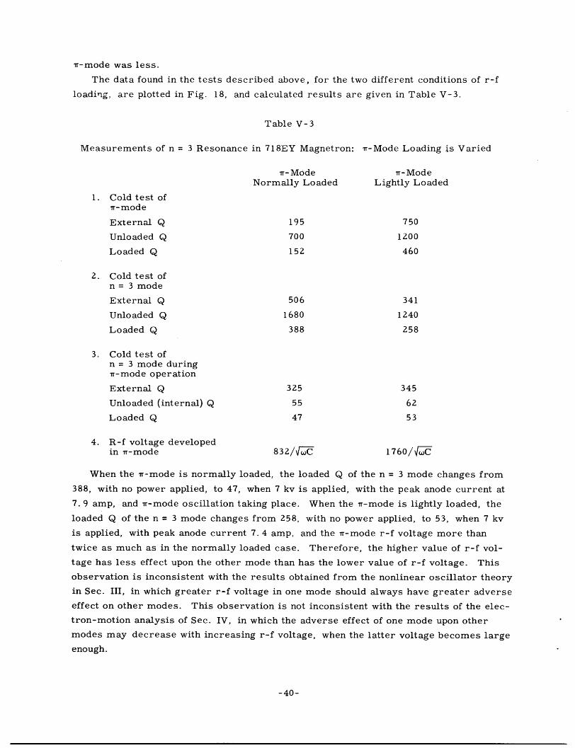
r-mode was less.
The data found in the tests described above, for the two different conditions of r-f
loading, are plotted in Fig. 18, and calculated results are given in Table V-3.
Table V-3
Measurements of n = 3 Resonance in 718EY Magnetron: Tr-Mode Loading is Varied
vr-Mode Tr-ModeNormally Loaded Lightly Loaded
1. Cold test ofr-mode
External Q 195 750
Unloaded Q 700 1200
Loaded Q 152 460
2. Cold test ofn = 3 mode
External Q 506 341
Unloaded Q 1680 1240
Loaded Q 388 258
3. Cold test ofn = 3 mode duringr-mode operation
External Q 325 345
Unloaded (internal) Q 55 62
Loaded Q 47 53
4. R-f voltage developedin rr-mode 832/~-C 1760/ -C
When the -mode is normally loaded, the loaded Q of the n = 3 mode changes from
388, with no power applied, to 47, when 7 kv is applied, with the peak anode current at
7.9 amp, and -mode oscillation taking place. When the Tr-mode is lightly loaded, the
loaded Q of the n = 3 mode changes from 258, with no power applied, to 53, when 7 kv
is applied, with peak anode current 7. 4 amp, and the rr-mode r-f voltage more than
twice as much as in the normally loaded case. Therefore, the higher value of r-f vol-
tage has less effect upon the other mode than has the lower value of r-f voltage. This
observation is inconsistent with the results obtained from the nonlinear oscillator theory
in Sec. III, in which greater r-f voltage in one mode should always have greater adverse
effect on other modes. This observation is not inconsistent with the results of the elec-
tron-motion analysis of Sec. IV, in which the adverse effect of one mode upon other
modes may decrease with increasing r-f voltage, when the latter voltage becomes large
enough.
-40-
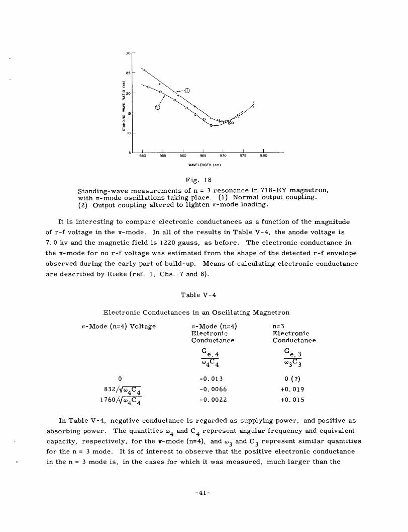
30
25
o0F 204
'I
15
zoz
10
I I I I I I I950 955 960 965 9.70 9.75 9.80
WAVELENGTH (cm)
Fig. 18
Standing-wave measurements of n = 3 resonance in 718-EY magnetron,with r-mode oscillations taking place. (1) Normal output coupling.(2) Output coupling altered to lighten *r-mode loading.
It is interesting to compare electronic conductances as a function of the magnitude
of r-f voltage in the wt-mode. In all of the results in Table V-4, the anode voltage is
7.0 kv and the magnetic field is 1220 gauss, as before. The electronic conductance in
the Tr-mode for no r-f voltage was estimated from the shape of the detected r-f envelope
observed during the early part of build-up. Means of calculating electronic conductance
are described by Rieke (ref. 1, -Chs. 7 and 8).
Table V-4
Electronic Conductances in an Oscillating Magnetron
t-Mode (n=4) Voltage rr-Mode (n=4) n=3Electronic ElectronicConductance Conductance
Ge Ge, 4 Ge, 3
4C4 03C 3
0 -0. 013 0 (?)
832/wt 4 C4 -0. 0066 +0. 019
1760 /-/ -0. 0022 +0. 015
In Table V-4, negative conductance is regarded as supplying power, and positive as
absorbing power. The quantities w4 and C4 represent angular frequency and equivalent
capacity, respectively, for the r-mode (n=4), and 3 and C 3 represent similar quantities
for the n = 3 mode. It is of interest to observe that the positive electronic conductance
in the n = 3 mode is, in the cases for which it was measured, much larger than the
-41-

700
600
5a 500-J0
y4 0
0
.r1
"v0 02 0.4 0.6 Q8 1.0 12 1.4PLATE CURRENT DURING PULSE (AMP)
Fig. 19
Steady-state V-I curve low-power rising-sun magnetron.B= 1410 gauss. For identification of modes, see Table V-5.
magnitude of negative conductance in the rr-mode, except for very small -mode r-f
voltages.
The results of these tests are, to some extent, doubtful as to accuracy, because it
was not possible to plot very accurate curves of standing wave ratio. Apparently the
observed values of standing wave ratio were subject to considerable random error, and
the calculated values for loaded Q, based on the same resonance curve, showed con-
siderable inconsistency. The variations of external Q were particularly disconcerting.
When electronic conditions were changed, the loading of a resonant mode should be
expected to occur entirely within the magnetron. Yet, there appeared to be substantial
variations of external Q, even though no change had been made in the r-f output circuit.
These effects are thought to be an experimental error not of a fundamental nature.
Because the worst inconsistencies in external Q appear where the internal (or unloaded)
Q has a much lower value, it is the internal Q which affects the loaded Q most under
these circumstances, and inconsistencies in external Q are considered to be much less
important than values of internal Q.
In spite of the apparent inconsistencies in data, the effects observed are so large
that it is difficult to conceive how any reasonably large errors in measurements could
obscure the correct results in principle.
Observations of Mode Changes
Mode Changes: Low-Power Rising-Sun Magnetron
The first experiment to be described here involves a specially constructed 18-vane
low power magnetron of the rising-sun type. This magnetron was originally intended
for c-w operation, but this was prevented because of the fact that under c-w conditions,
-42-
_ ____10ME C
_- MODE B
-MODE
I I I I I I

cathode heating was excessive. Instead, operation with long pulses was carried on,
with pulse durations of 10 to 20 ~sec, or more.
All the tests described here were performed with a magnetic field of 1410 gauss.
With the r-f load matched to the output coaxial transmission line, the voltage-current
relationships were as shown in Fig. 19. Under these conditions, three different modes
were observed, labeled A, B and C. These modes are described in Table V-5. The
identification of each mode was made by means of a rotating probe. The values of n,
for modes B and C especially, were not perfectly clear, but the values specified in
the table seem to be consistent with mode-spectrum theory for rising-sun magnetrons
(ref. 3, p. 229). If values of n are known, the values of y are quite unambiguous,
because the starting voltages, functions of y and frequency, were observed.
Table V-5
Mode Identification in Low-Power Rising-Sun Magnetron
Identification of Mode Wavelength (cm)
Mode A 9/9/18 (-mode) 11.48
Mode B 6/3/18 14. 25
Mode C 7/2/18 14. 62
When a slowly rising voltage pulse (rise time, 20 sec) was applied to this magne-
tron, oscillation was observed successively in modes A, B and C, and during the fall
of voltage, oscillation shifted from C back to A; these changes are shown in Fig. 20.
The test described here was to determine whether the change from one mode to the
next depended primarily upon conditions in the original mode, conditions in the next
mode, or a combination of both. To
PLATE VOLTAGE reach any satisfactory conclusions on
this question, it was necessary to alter
conditions in one mode without affecting
others. The condition which was altered
for each mode was the external loading.
This was accomplished separately forR-F ENVELOPE
.~~~~~~~~~~1 _~LI4 IJnh I±±>zI1 LII stati of JLJ en LJi_C'uC:11 'lIULt UY V11U1 Us a11 Fubul-Llull-
type wavemeter, as shown in Fig. 21.
The loading for each mode is changed by
a small but appreciable amount as the
wavemeter is tuned to thnt mode: hut. -, -_ -_ _ L _ _ _ _ _ _ L L__ --t-
tuning to the frequency of one particular
mode has virtually no effect on otherDrawings taken from synchroscope traces,showing how the positions of mode shifts modes.are affected by changes in loading. When the wavemeter was tuned to
-43-

TO CRYSTAL DETECTORLOW- POWER | AND SYNCHROSCOPEMAGNETRON LONG LOSSY LINE7FLEXIBLE CABLE
SLOTTED SECTION WAVEMETEROF 7/8 COAXIAL
LINE
Fig. 21 Fig. 22
R-f portion of test equipment for Current pulse associated with modeload-variation experiment with changes in low-power rising-sunlow-power rising-sun magnetron. magnetron. Conditions are the same
as in Figs. 19 and 20.
mode A, the boundary between A and B was changed from the position shown by the
solid line in Fig. 20 to that shown by the dashed line. No effect upon the boundary
between C and A was produced. Tuning the wavemeter to the frequency of mode B
affected the ending of that mode in a manner shown by the dashed line, but did not affect
its starting. Tuning the wavemeter to the frequency of mode C showed the same kind
of results. These results indicate that the conditions for shifting from any one of these
modes to another are determined primarily by the characteristics of the mode initially
oscillating, and are not affected by the mode which is found immediately after the initial
mode has become unstable, no matter whether the voltage shift which gave rise to the
mode change is upward or downward.
These results are confirmed by synchroscope observation of the anode current, as
shown in Fig. 22. Each of the mode change boundaries is accompanied by a vertical
spike, indicating a sharp reduction of current during the transition. Since current in
an oscillating magnetron can flow only as a consequence of oscillation, the reduction in
current evidently corresponds to cessation of oscillation in the original mode, followed
by the building-up of oscillation in the subsequent mode. It should be pointed out that
the signal on the synchroscope (Fig. 22) has passed through a video amplifier, and
therefore, the limited frequency response (about 10 Mc/sec) may have reduced the
sharpness of the spike which corresponds to the reduction of current.
Mode Changes: 2J54 Magnetron
The 2J54 magnetron has an eight-cavity strapped anode with hole-and-slot construc-
tion, fundamentally similar to the 2J32 (ref. 1, pp. 751-756). It differs from the 2J32
slightly in wavelength, and also because it is tunable. The characteristic which is of
interest here is that it sometimes oscillates in the 5/3/8 mode at a slightly lower anode
voltage than that for which it begins to oscillate in the r-mode. For certain values of
magnetic field and a reflectionless output line, oscillation was observed to begin in the
5/3/8 mode, and to persist even after the applied voltage had reached a value at which
the rr-mode could build up. The r-f envelope observed under these circumstances is
shown in Fig. 23. The step observed in the leading edge was found to correspond to the
n = 3 resonance, and the value of applied voltage identified it as the 5/3/8 mode.
-44-
I _

Fig. 23
R-f envelope for 2J54 magne-tron, showing initial oscillationin the 5/3/8 mode, followed byir-mode oscillation. Pulse dura-tion = 2 Ulsec.
shifted in position, the time of the
the start of the pulse. The change
to be a relatively large part of the
slightly greater than that at which
the short circuit was made over a
To determine the nature of the transition from
the 5/3/8 mode to the rr-mode, the output coaxial
line was terminated in a movable mismatch. The
mismatch consisted of a movable short circuit,
with a high-power attenuator (about 10 db) between
the short circuit and the magnetron. Thus, the
wave reflected by the short circuit represents
about 0. 01 in power and 0. 1 in voltage of the wave
traveling toward the load, when this measurement
is made between the magnetron and the attenuator.
Thus, a considerable change in magnetron loading
could be made by the position of the reflection.
It was observed that as the short circuit was
transition between modes also changed in relation to
in the relative time of the transition could be made
pulse duration if the value of applied voltage was only
the transition takes place. A shift of the position of
distance great enough so that the relative position of
the mode transition moved from one extreme to the other and back again. The distance
over which the short circuit had to be shifted, to accomplish the change from one
extreme and back to the same extreme, was measured several times; this measurement
was repeated with the relative time of the transition starting from and returning to the
other extreme value. The average values of the distance over which the short circuit
had to be moved in order to restore conditions to their original state were found to be
4. 64 cm and 4. 65 cm for the two sets of measurements. Since moving a reflection by
half of a wavelength produces no net change in impedance as measured at the generator,
the above values for the distance over which the reflection was moved should be helpful
in indicating which of the two modes controlled the transition. The wavelength for the
rr-mode is 9. 45 cm, and that for n = 3 is 8. 16 cm. The above experimental values
correspond more nearly to a half wavelength of the i-mode.
It is therefore apparent that mode competition takes place during this transition,
and that conditions in the second mode to oscillate, the w-mode, affect the transition
more than do conditions in the first. The mode-competition interpretation of this mode
change is further supported by the fact that no decay of the 5/3/8 mode preliminary to
starting of the w-mode can be observed in the synchroscope trace of the r-f envelope,
shown in Fig. 23. In making this observation, it is significant that a broadband diode
detector (100-Mc/sec bandwidth) was used, without a video amplifier between detector
and deflecting plates.
Mode Stability: Suppression of Unwanted Modes in the 2J39 Magnetron
An attempt was made to measure mode changes of the type described in the above
-45-

subsections, using a 2J39 magnetron (ref. 1, pp. 747-751). This attempt was thwarted
by the absence of any oscillating modes other than the T-mode. Stable oscillation was
observed, for normal magnetron loading, over a range of anode voltages extending from
somewhere below the theoretical T-mode threshold voltage all the way to d-c cutoff,
and for a wide range of values of magnetic field. Thus, none of the usual mode change
or mode stability problems were encountered at all. The range over which r-mode
stability was observed is shown in Fig. 24.
When the d-c cut-off voltage was approached, and oscillation began to fall off
sharply, anode current continued to increase smoothly and with no suggestion of a
discontinuity. Theoretical values of anode current which should flow at d-c cutoff were
computed (ref. 5) for two different values of magnetic field. At 1750 gauss, the theo-
retical d-c current at cutoff is 21.2 amp; the maximum current at which stable r-mode
oscillation was observed was 19.6 amp. At 1950 gauss, theoretical direct current is
25. 8 amp; maximum current for stable Tr-mode oscillation was 25. 2 amp. Therefore,
the theoretical anode current at d-c cutoff was approached very closely before T-mode
oscillation ceased.
Another important point shown by Fig. 24 is that stable r-mode oscillation was
observed well above the theoretical starting voltage for the 3/3/8 mode. This refutes,
if any further refutation is necessary, the mode change theories which have been based
primarily on the notion that a lower voltage mode cannot exist when the anode voltage
z
04
-J0
MAGNETIC FIELD IN GAUSS
Fig. 24
Limits of Tr-mode oscillation in 2J39 magnetron.
-46-

reaches the threshold value for the next higher-voltage mode. It is also significant that
Tr-mode operation is observed here at voltage levels in excess of the instability voltage
for the 3/3/8 mode (refs. 22 and 8). (The instability voltage was taken up in Sec. I. )
The history of the development of the 2J39 magnetron is interesting in the light of
the results presented here. Early models of the 2J39 experienced Tr-mode instability
at low values of anode current. The problem was studied by Fletcher and Rieke (ref. 17)
who recommended changes in the magnet pole pieces which would make the magnetic
field in the interaction space more uniform. The model of the 2J39 tested here was one
in which these changes had been made.
Summary
In the preceding subsections, various types of mode change phenomena have been
discussed. In all of these, the most fundamental observation expressed by the theoreti-
cal work in Secs. III and IV is borne out: that large amplitude oscillation in one mode
tends to suppress other modes. In the low-power rising-sun magnetron, it was observed
that after oscillation in one mode had been established, other modes of oscillation could
not start until the one had collapsed, and in each case this collapse was apparently inde-
pendent of other modes. In the 2J39, suppression of other modes by the rt-mode was
so effective that the other modes were not observed. Of the magnetrons considered
here, only in the 2J54 was the build-up of another mode in competition with the original
mode observed. The latter case is by no means in contradiction with the theoretical
arguments of Secs. III and IV. The maximum amplitude achieved by oscillations in the
5/3/8 mode, the initially oscillating mode, was very small as compared with Tr-mode
oscillations (see Fig. 23). For reasons explained in Sec. II, it should be expected that
the electron bunching in the 5/3/8 mode would be less effective than in the r-mode, due
to the presence of a third-order component, as well as the fifth-order component to
which the electrons are coupled. Therefore, the suppression of the rt-mode by the
5/3/8 mode might well be expected to be relatively ineffective. Furthermore, it was
perfectly clear that the presence of the 5/3/8 mode caused an appreciable delay in the
starting of the r-mode.
VI. Correlation of Theory and Experiment: Summary and Conclusions
Mode Competition During Build-Up
The subject of mode competition during the build-up transient has been analyzed
rather thoroughly by Rieke (ref. 1, Ch. 8). It was stated in Sec. III that the validity of
his analysis depends upon the assumption that when nonlinear effects become important,
the dependence of the rate of build-up in one mode upon r-f amplitude in the other mode
is greater than upon its own amplitude. Rieke stated that this assumption is open to
question. Evidently he questioned the assumption only because he had no theoreticaljustification for it. It is apparent that he realized that it must be true, if mode selection
-47-

for any one starting transient is to be definite. (This is not to say that different modes
cannot be selected on successive pulses, even though the applied pulses are identical. )
Otherwise simultaneous stable oscillation in two modes is possible, a condition rarely,
if ever, met with in practice.
From a theoretical point of view, Rieke' s assumption is supported by the nonlinear
oscillator theory discussed in Sec. III. Confirmation of the assumption is most obvious
in Eqs. 31 and 32 of that section, and these equations are based on the instantaneous3
voltage-current relationship, i = ae - be 3 . It is less obvious, but equally true, that the
conditions assumed in Sec. III, which led to the results shown graphically in Fig. 13,
also cannot lead to simultaneous stable oscillation in two modes. It is not entirely
impossible that some other r-f voltage-current characteristic could lead to circum-
stances in which two modes of oscillation could be stable simultaneously, but the most
plausible types of these relationships do not lead to such results. (See ref. 1, Ch. 8. )
Thus Rieke's assumption, according to him, "open to question, " can be supported both
theoretically and by observation of actual magnetron performance.
Therefore, magnetron build-up, when conditions allow either of two modes, proceeds,
presumably, from random noise, which tends to excite both modes. Build-up in each
mode is exponential in form, and more or less independent of the other, until nonlinear
effects begin to become important. Then competition begins to take place, and the
advantage lies more and more with the mode which has greater r-f field intensity for
electron bunching. It is r-f field intensity near the cathode, in the region in which
rejection of unfavorable electrons takes place, which is most important. Then it
becomes necessary that the magnitude of oscillation in the mode which has the greater
bunching effect should reduce the rate of build-up in the other mode more than the
magnitude of oscillation in the other mode should affect its own rate of build-up. This
condition causes the mode with more effective bunching to become progressively
stronger than the other, and eventually to suppress it altogether.
Mode Stability
The mode stability problem can be summarized more quickly than the mode selec-
tion problem. The results which have been obtained show that if the anode voltage
applied to a magnetron is raised slowly, as compared with the rate of build-up of the
mode or modes under consideration, until the starting voltage of another mode has
been reached, the advantage lies with the mode which started first, and unless the
first mode is relatively weak, the second will not build up. Among all the magnetrons
discussed in Sec. V, there was none in which the rr-mode failed as a result of competi-
tion with another mode, and only one other mode in one magnetron which failed as a
result of competition. In the other cases, any shift which took place from one mode to
another was primarily the result of collapse of the first mode, independent of others,
rather than the result of competition from the second.
The outstanding example of w-mode stability was the 2J39, in which the upper limit
-48-

on input voltage, and consequently on input current, was d-c cutoff. From the mode
interaction point of view, it is significant to point out that nr-mode oscillation continued
at a value of anode voltage far above the theoretical threshold voltage of the next higher-
voltage mode.
Magnetron Design Considerations
The ultimate object of studying the fundamental principles of mode interactions in
magnetrons is to improve magnetron design, and methods of magnetron design. A
clearer understanding of fundamentals not only makes better magnetrons possible, but
makes the process of reaching a good design more direct and less expensive.
The fundamental requirements involving magnetron modes in pulsed magnetrons
are, first, the establishment of large amplitude oscillation in the desired mode (nearly
always the -mode), and second, the maintenance of stable oscillation in that mode for
the duration of the applied pulse. In c-w magnetrons, the maintenance of stability is
as important as in pulsed magnetrons.
R-f Feedback
In promoting quick starting, in order to avoid misfiring, and in promoting greater
steady-state stability, in order to increase the maximum power obtainable from
a magnetron, the r-f feedback system is very important. It can be altered by
changing the loading of the magnetron, or by changing the magnetron structure itself.
Of the possible modifications of the structure, the one which has the most effect is
changing the ratio of cathode radius to anode radius. The reason for the great effect
which this change leads to is the rate at which the intensity of the r-f electric field falls
off as the cathode is approached, as discussed in Sec. II. Therefore, the rate of build-
up, and to a smaller degree, the steady-state stability, are very sensitive to changes
in cathode diameter, with a larger cathode radius leading to faster build-up and more
stability. The larger cathode leads incidentally to greater preoscillation noise. Since
oscillations must build up from noise, more noise means a greater initial amplitude of
oscillation, and the length of time required for building-up is less. Such an effect has
been reported by Forsberg (Private communication from P. W. Forsberg to F. F. Rieke;
reported by Rieke in ref. 1, Ch. 8, p. 379).
Many magnetron designers have improved stability and reduced misfiring by
increasing the ratio of cathode radius to anode radius. This was done by the General
Electric Company, Ltd., in England, where it was associated with instability voltages
(see Sec. II, also refs. 22 and 8). It was done by the Bell Telephone Laboratories
(ref. 18), who associated with an increase in Io, the characteristic current for a given
mode in any particular magnetron; this characteristic current was derived from d-c
magnetron considerations by Allis, and was applied to the oscillating magnetron by
Slater, in absence of any other current which could be clearly defined from theoretical
considerations (ref. 5). Finally, it has been done by the Litton Industries, where it
-49-
was associated with the perveance of a simple diode (ref. 21). The sensitivity of mis-
firing and stability performance of actual magnetrons to this kind of design change is
not adequately explained by any of these criteria.
There may be two adverse effects of increasing the cathode radius with respect to
the anode radius. The first is the increased stability and the faster build-up of lower
voltage modes, which may delay or prevent the starting of the desired mode. The
second is a reduction in electronic efficiency.
Mode Interactions
The first and best-known requirement involving interactions between modes is to
keep oscillation in one mode from exciting r-f field components of any other mode. This
requires adequate separation of other modes from the desired modes in frequency; the
most usual means of separation is the use of strapped anodes or of rising-sun anodes.
What constitutes adequate separation has never been clearly set forth. Certainly it must
be at least equal to several bandwidths of both the desired mode and of any potentially
interfering mode. It may also be desirable to separate modes to the extent that the
resonant frequency of a mode whose threshold voltage might be lower than that of the
desired r-mode instead becomes higher than that of the r-mode; therefore the unwanted
mode has no chance to build up ahead of the vr-mode and interfere with Tr-mode starting.
For example, in the 2J54 magnetron (see Sec. V) oscillation in the 5/3/8 mode was
found to interfere with the starting of the Tr-mode; one possible method of removing this
interference is to increase the frequency of the n = 3 resonance so that the 5/3/8 mode
would have a higher starting voltage than the rr-mode.
The topic which has been of chief concern here has been the interaction of modes
through the electron stream. These results point to the conclusion that once an oscil-
lating mode, for which electron bunching is complete, or almost complete, has been
established, it is extremely unlikely and perhaps impossible for another mode to build
up in its presence, and suppress it. Even when a mode of oscillation is relatively weak,
such as the 5/3/8 mode in the 2J54 magnetron, it still can have a considerable adverse
effect on a substantially stronger mode. Unless the initially oscillating mode is quite
weak, oscillation will shift to another mode primarily as a result of the failure of the
initial mode, substantially apart from any effect by the subsequently oscillating mode.
There are two respects in which these conclusions may be applied to magnetron
design: first, the increase of maximum power in the desired mode; second, the sup-
pression of unwanted lower voltage modes.
The suppression of unwanted lower voltage modes has been definitely demonstrated
to be of importance. A strongly oscillating unwanted mode can prevent the starting of
the r-mode until the unwanted mode collapses as a result of its own properties; a less
strongly oscillating mode can interfere seriously with r-mode starting, as in the 2J54.
The unwanted modes can be discouraged by systematically making them less stable
by interfering with the feedback mechanism (see subsection on r-f feedback); it is
-50-
_ __

regrettable that decreasing the cathode diameter for this purpose also affects the
rr-mode stability adversely. Their r-f field pattern can be distorted, as by strap
breaks, which are presumed to affect the T-mode pattern less than that of other modes.
However, the effectiveness of strap breaks has never been clearly established. The
unwanted modes can also be removed from the region of lower voltage modes to the
region of modes with higher voltages than the -mode, as described above. When the
starting voltage of the unwanted mode is higher than that of the r-mode, it can be com-
pletely suppressed by a strongly oscillating T-mode; this time, the tendency of the
originally oscillating mode to persist against modes which might oscillate under the
existing conditions of magnetic field and anode voltage if the original mode were not
there works against the unwanted mode.
However, lower voltage modes are usually not a serious problem. The low voltage
mode in the 2J54 disappeared when a higher magnetic field was used. A similar mode,
although theoretically possible in the 2J39 magnetron, was never observed. Rising-sun
magnetrons are usually free from interference by modes of lower starting voltage than
the rr-mode.
Turning our attention now to the application of these principles to extending the
maximum power limit of rr-mode operation in the face of possible competition from
unwanted modes, we find that the presence of other possible modes at the desired oper-
ating voltage does not necessarily prevent satisfactory oscillation in the r-mode at this
voltage. Instead, we find that it is possible to establish Tr-mode oscillation in a voltage
range suitable for rr-mode build-up, after which the voltage may continue upward
indefinitely until some inherent instability of the Tr-mode itself sets in. This type of
limitation is not well understood from a quantitative point of view, but methods of
extending it have been discussed above. It may be recalled here that in a properly
loaded 2J39 magnetron, the limitation on w-mode stability coincided with d-c cutoff.
On the basis of competition from other modes, there appears to be no fundamental limi-
tation on magnetron power. There appears to be no basis yet for predicting the maxi-
mum power available from a magnetron from rr-mode failure considerations, other than
that imposed by d-c cutoff.
Magnetic Field Uniformity
A very important factor in stability is the uniformity of the magnetic field. This
problem is usually not serious in unpackaged magnetrons, where the magnet is entirely
exterior to the magnetron; only a small portion of the magnet gap, both in terms of
diameter and in terms of length, is included in the interaction space. This is not the
case for packaged magnetrons. In these magnetrons, the magnet gap has been shortened
and decreased in diameter by bringing the magnet poles through the end plates and as
close to the interaction space as possible. Under these circumstances, it is more dif-
ficult to make the magnetic field uniform.
Two examples of improvements in magnetic field uniformity will be discussed here.
-51-
_�____l__lll__gllllLI___II�

The 2J39 was changed from a magnetron with unsatisfactory stability characteristics to
one with unusually good stability by redesigning the pole pieces to produce a more uni-
form magnetic field (ref. 17). A relatively uniform magnetic field in the 4J50 magne-
tron was made possible by means of cathode and shields made of permendur, a
ferromagnetic alloy with a very high Curie temperature (ref. 3, pp. 329-330).
Reasons for the adverse effects of nonuniform magnetic fields have been discussed
in Sec. II. Their importance is emphasized by the great improvement in 2J39 operation
by means of small changes in the pole-piece dimensions.
Cathode Performance
The need for adequate cathode emission has long been recognized as fundamental to
good magnetron oscillation. It has been shown here that good starting and stability
characteristics which result from good cathode performance characteristics may be
associated with the properties of a magnetron considered as a feedback amplifier. In
a magnetron, the cathode performance is analagous to cathode performance in a triode
feedback oscillator. Good performance in the triode oscillator or in the magnetron is
dependent on the loop transmission (defined in Sec. II); the loop transmission may be
substandard if cathode performance is poor. In the magnetron it is especially important.
that the equivalent loop transmission be high for high values of anode voltage, for under
these conditions, the tendency for electrons to get out of step with the r-f wave is
strong.
Summary
The principal idea which has come from this research is that large-amplitude
oscillation in one mode tends quite strongly to suppress oscillation in other modes.
This supports the mode-competition theory advanced by Rieke (ref. 1, Ch. 8,
pp. 380-387). On the other hand, it contradicts all mode stability and mode change
criteria based primarily on the effects of other modes upon a strongly oscillating mode.
For example, it is not necessarily true that when the necessary conditions for oscilla-
tion in the next higher voltage mode are met, the originally oscillating mode will give
way to the mode with the higher starting voltage; on the contrary, if the first mode is
one which oscillates strongly, it is much more likely that the first one will persist, and
the second will arise only after conditions are such that the first mode will collapse,
primarily independent of conditions in the second mode.
It is therefore true that no fundamental limitation upon high power in magnetrons
exists as a result of the possible presence of unwanted modes, provided oscillation in
the desired mode can be firmly established. No fundamental limitation on high power
in magnetrons could be found which is associated with mode instability, except when
d-c cutoff was reached; whether or not another limit exists is still open to question.
Therefore, the fundamental requirement both for quick starting, in order to avoid
misfiring, and for stability, with or without the possible presence of other modes, is
-52-

to establish and maintain effective electron bunching throughout the entire anode length.
Acknowledgment
The author wishes to express his appreciation to his supervisor,
Professor S. T. Martin, who suggested this topic for research, has encouraged it, and
has been the source of many valuable suggestions. He also wishes to acknowledge the
contribution made by others of the staff of the Research Laboratory of Electronics,
including Professor W. P. Allis, who has been very helpful in assisting with theoretical
work; Mr. L. D. Smullin, who has made some very important suggestions on experi-
mental techniques; and Mr. W. E. Vivian who first suggested the application of
van der Pol' s nonlinear oscillator theory to magnetrons.
Bibliography
1. G. B. Collins (editor): Microwave Magnetrons, M.I. T. Radiation LaboratorySeries 6, McGraw-Hill, 1948
2. J. C. Slater: Microwave Electronics, Van Nostrand, 1950
3. J. B. Fisk, H. D. Hagstrum, P. L. Hartman: The Magnetron as a Generator ofCentimeter Waves, B.S.T.J. 25, 167, April 1946
4. J. C. Slater: Theory of the Magnetron Oscillator, M.I.T. Radiation LaboratoryReport V-5s, Aug. 1941
5. J. C. Slater: Theory of Magnetron Operation, M. I. T. Radiation Laboratory Report43-28, March 1943
6. H. A. H. Boot, J. T. Randall: The Cavity Magnetron, J.I.E.E. 93, 928, part IIIA,1946
7. E. C. S. Megaw: The High-Power Pulsed Magnetron: a Review of Early Develop-ments, J.I.E.E. 93, 977, part IIIA, 1946
8. W. E. Willshaw, L. Rushforth, A. G. Stainsby, R. Latham, A. W. Balls,A. H. King: The High-Power Pulsed Magnetron. Development and Design forRadar Applications, J.I. E. E. 93, 985, part IIIA, 1946
9. (Discussion of refs. 6, 7, and 8; J.I.E.E. 95, 130, part III, also see refs. 1 and 3)
10. J. C. Slater: Resonant Modes of the Magnetron, M. I. T. Radiation LaboratoryReport No. 43-9, Aug. 1942
11. Centimeter Magnetrons, National Defense Research Committee, Division 14,Report No. 588, Columbia Radiation Laboratory, April 1946
12. R. R. Moats: Investigation of Anode Structure in a Rising-Sun Magnetron, TechnicalReport No. 99, Research Laboratory of Electronics, M.I. T. May 1949
13. J. Sayers: The Modes of Resonance in a Multi-Segment Magnetron and Mode-Locking Straps to Ensure High-Efficiency Operation, CVD Report Mag. 7,Birmingham University, Sept. 1941
14. R. C. Fletcher, F. F. Rieke: Mode Selection in Magnetrons, M.I. T. RadiationLaboratory Report No. 809, Sept. 1945
-53-

15. M. Healea: Effect of Variation of Vane Width and Cathode Size on the Operation ofMagnetrons, M.I.T. Radiation Laboratory Report No. 586, Aug. 1944
16. D. R. Hartree: Mode Selection in a Magnetron by a Modified Resonance Criterion,CVD Report Mag. 17, Manchester University
17. R. C. Fletcher, F. F. Rieke: An Improvement in the Raytheon 2J39 Magnetron,M.I.T. Radiation Laboratory Report 52, Jan. 1944
18. H. D. Hagstrum, W. B. Hebenstreit, A. E. Whitcomb: On the Maximum CurrentLimitations Encountered in L-Band Magnetrons, Bell Telephone LaboratoriesReport MM-45-2940-2, June 1945
19. R. R. Moats: Mode Stability in Resonant-Cavity Magnetrons, Master's Thesis,Dept. of Electrical Engineering, M. I. T. 1947
20. D. A. Wilbur et al: C-W Magnetron Research: Final Report, General ElectricCompany Research Laboratories, Schenectady, N.Y., April 1950
21. Engineering Reports No. 11-1 through 11-20: 1 Kw. C-W Tunable Magnetrons,Litton Industries, San Carlos, California, June 1948-April 1950
22. D. T. Copley, W. E. Willshaw: A Criterion for the Assessment of the ModeChange Performance of Magnetrons, Report No. 8490, General Electric Company,Ltd. Aug. 1944
23. B. van der Pol: On Oscillation Hysteresis in a Triode Generator with Two Degreesof Freedom, Phil. Mag. 43, 700, April 1922
24. B. van der Pol: The Nonlinear Theory of Electrical Oscillations, Proc. I.R.E.22, 1051, Sept. 1934
25. A. A. Andronow, C. E. Chaikin: Theory of Oscillations, English Language Edition,Solomon Lefschetz, editor, Princeton University Press, 1949
26. J. J. Stoker: Nonlinear Vibrations, Interscience Publishers, 1950
27. J. Brossart, O. Doehler: Sur les propri6t6s des tubes a champ magnetique con-stant, Annales de radio6lectricit6 3, 329, Oct. 1948
28. R. R. Warnecke, W. Kleen, A. Lerbs, O. Doehler, H. Huber: The Magnetron-Type Traveling-Wave Amplifier Tube, Proc. I.R.E. 38, 486, May 1950
29. J. F. Hull, A. W. Randals: High Power Interdigital Magnetrons, Proc. I. R. E.36, 1357, Nov. 1948
30. K. Posthumus: Oscillations in a Split-Anode Magnetron, Wireless Engineer 12,126, 1935
31. R. Q. Twiss: On the Steady-State and Noise Properties of Linear and CylindricalMagnetrons, Doctoral Thesis, Dept. of Physics, M.I.T. 1949
32. R. C. Fletcher, G. M. Lee: Preliminary Studies of Magnetron Build-Up, NDRCDivision 14, Report No. 543, Laboratory for Insulation Research, M. I. T. Nov.1945
-54-