Embed Size (px)
Citation preview
Turk J Elec Eng & Comp Sci
(2013) 21: 1685 – 1702
c⃝ TUBITAK
doi:10.3906/elk-1112-76
Turkish Journal of Electrical Engineering & Computer Sciences
http :// journa l s . tub i tak .gov . t r/e lektr ik/
Research Article
Interaction analysis of multifunction FACTS and D-FACTS controllers by MRGA
Maghsood MOKHTARI,∗ Javad KHAZAIE, Daryoush NAZARPOUR, Morteza FARSADIDepartment of Electrical Engineering, Faculty of Engineering, Urmia University, Urmia, Iran
Received: 26.12.2011 • Accepted: 16.05.2012 • Published Online: 02.10.2013 • Printed: 28.10.2013
Abstract: With the growing application of flexible AC transmission systems (FACTS) and distributed FACTS (D-
FACTS), the coordinating problem of FACTS and D-FACTS controllers in joint operation must be considered in modern
power systems. The main purpose of this paper is to investigate the possible interaction that may occur between
the distributed static series compensator (DSSC) and the static synchronous compensator (STATCOM) when they
operate concurrently in the power system. The modified relative gain array (MRGA) is implemented to analyze the
interactions. The application of MRGA for the effective design of multiobjective controllers of the STATCOM and
DSSC is demonstrated by 2 cases of study: the first case includes the contradiction among the AC voltage control,
DC link capacitor voltage control, and power oscillation damping controller of the STATCOM, and the second case is
dedicated to the interaction between the different controllers of the DSSC and the STATCOM. The simulation results
are carried out in PSCAD/EMTDC in order to verify the results obtained from MRGA analysis in both cases of study.
Key words: Flexible AC transmission systems, distributed FACTS, static synchronous compensator, distributed static
series compensator
1. Introduction
Transient dynamic stability is of increasing importance for the safe operation of power systems in a modern
integrated power network. The flexible AC transmission system (FACTS) is a newly developed technology
that can greatly improve the transient stability margin via appropriate control strategy [1–3]. In practical
applications, several static synchronous compensators (STATCOMs) have been installed worldwide. Compared
with the traditional reactive power compensation devices, the STATCOM has better dynamic response, large
compensation range, less dependence on the system voltage, and low harmonic content.
Recently, a new concept from the family of distributed FACTS (D-FACTS) has been introduced as a
way to offer all of the capabilities of their FACTS counterparts, but in a most efficient way. The distributed
nature of the suggested system makes it possible to achieve fine granularity in the system rating. Furthermore,
it is possible to expand the system with the growing demand [4–6]. The distributed static series compensator
(DSSC), as a new D-FACTS device, is composed of a low-power single-phase inverter that attaches directly to
the transmission line conductor [7]. It should be emphasized that in order to preserve the transmission system
symmetry, all 3 phases of the line in question are identically equipped. The distributed nature of these devices
enables a fine granularity in the system rating, which, in turn, makes it possible to boost the transmission
system along with the growing demand. This opportunity grants a salient benefit in the system’s planning since
∗Correspondence: [email protected]
1685
MOKHTARI et al./Turk J Elec Eng & Comp Sci
the increasing requirement for power transfer capabilities would gradually be satisfied by installing new DSSC
modules in the most effective line(s).
In large interconnected networks, the placement of more than one FACTS device in some regions or
electrical areas will be the natural consequence of the growing use of this technology. Furthermore, with
improvement of D-FACTS devices, the deployment of D-FACTS and FACTS devices concurrently will be more
beneficial in the power system’s transient stability. The unique feature of these new-generation FACTS devices
is their multiple control function. For instance, the DSSC has the primary duty of power flow control, but it
can handle secondary duties such as subsynchronous oscillation damping and low frequency oscillation damping
[8–10].
Aside from these merits cited above, the implementation of more than one FACTS device or multifunction
FACTS controller may lead to adverse interactions. These interactions can occur in the following combinations
[11]:
• Multiple FACTS controllers of a similar kind.
• Multiple FACTS controllers of diverse kinds.
• Multiple FACTS controllers and high-voltage DC controllers.
These different control interactions have been classified into 5 frequency ranges [11]:
• 0 Hz for steady-state interactions,
• 0–3 or 5 Hz for electromechanical oscillations,
• 2–15 Hz for small-signal or control oscillations,
• 10–50/60 Hz for subsynchronous resonance interactions,
• >15 Hz for electromagnetic transients, high-frequency resonance or harmonic resonance interactions, and
network-resonance interactions.
There are many papers that have attempted to analyze the adverse interactions between FACTS con-
trollers. For instance, Wang and Zhang et al. [12,13] demonstrated the interaction assessment of FACTS control
using the relative gain array (RGA) method. Moreover, analysis of the interaction between the multiple control
functions of the unified power flow controller was investigated in [14].
To the best of the authors’ knowledge, this paper is the first attempt to study the interactions between a
multiobjective static compensator (STATCOM) controller and a multiobjective DSSC controller. Furthermore,
the high-frequency interactions as a result of exceeding the controller’s gain are clarified in this paper, which was
not addressed in other manuscripts. The modified RGA (MRGA) that was introduced in [14] is implemented
to measure the interactions between the multiple control loops of the STATCOM and DSSC in order to design
effective controllers. There are many other works that demonstrate the interaction of FACTS devices in power
systems [15–18].
The main structure of this manuscript is as follows: Section 2 describes a brief introduction of the DSSC
and its corresponding multiobjective controllers. The basic concept of the STATCOM with its normal and
auxiliary controller is described in Section 3. In Section 4, the MRGA in a multiple-input, multiple-output
(MIMO) system is introduced in order to measure the interaction among the different controllers of a power
system. The simulation results are presented in Section 5. Finally, the conclusions are given in Section 6.
1686
MOKHTARI et al./Turk J Elec Eng & Comp Sci
2. DSSC concept
The DSSC concept has been expressed based on FACTS devices, which is in fact a model of a static synchronous
series compensator but in a smaller size, at a lower price, and with higher capability. For more safety and
improvement in the controllability of power systems, it lies in the transfer lines in a distributed manner.
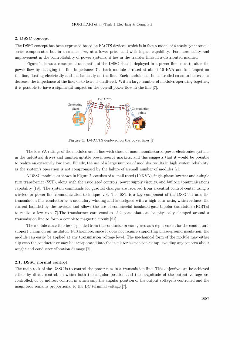
Figure 1 shows a conceptual schematic of the DSSC that is deployed in a power line so as to alter the
power flow by changing the line impedance [7]. Each module is rated at about 10 KVA and is clamped on
the line, floating electrically and mechanically on the line. Each module can be controlled so as to increase or
decrease the impedance of the line, or to leave it unaltered. With a large number of modules operating together,
it is possible to have a significant impact on the overall power flow in the line [7].
points
FACTSD-
Generating
plants Consumption
Figure 1. D-FACTS deployed on the power lines [7].
The low VA ratings of the modules are in line with those of mass manufactured power electronics systems
in the industrial drives and uninterruptible power source markets, and this suggests that it would be possible
to realize an extremely low cost. Finally, the use of a large number of modules results in high system reliability,
as the system’s operation is not compromised by the failure of a small number of modules [7].
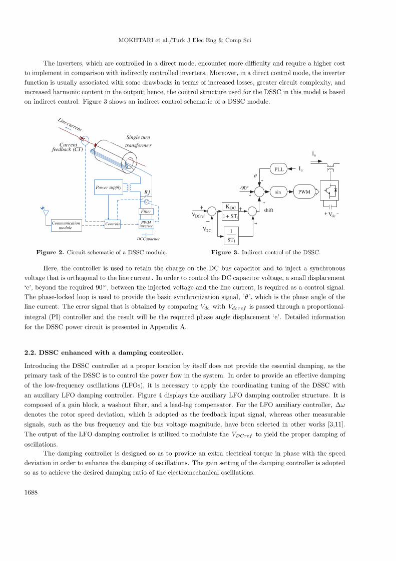
A DSSC module, as shown in Figure 2, consists of a small rated (10 KVA) single-phase inverter and a single
turn transformer (SST), along with the associated controls, power supply circuits, and built-in communications
capability [19]. The system commands for gradual changes are received from a central control center using a
wireless or power line communication technique [20]. The SST is a key component of the DSSC. It uses the
transmission line conductor as a secondary winding and is designed with a high turn ratio, which reduces the
current handled by the inverter and allows the use of commercial insulated-gate bipolar transistors (IGBTs)
to realize a low cost [7].The transformer core consists of 2 parts that can be physically clamped around a
transmission line to form a complete magnetic circuit [21].
The module can either be suspended from the conductor or configured as a replacement for the conductor’s
support clamp on an insulator. Furthermore, since it does not require supporting phase-ground insulation, the
module can easily be applied at any transmission voltage level. The mechanical form of the module may either
clip onto the conductor or may be incorporated into the insulator suspension clamp, avoiding any concern about
weight and conductor vibration damage [7].
2.1. DSSC normal control
The main task of the DSSC is to control the power flow in a transmission line. This objective can be achieved
either by direct control, in which both the angular position and the magnitude of the output voltage are
controlled, or by indirect control, in which only the angular position of the output voltage is controlled and the
magnitude remains proportional to the DC terminal voltage [7].
1687
MOKHTARI et al./Turk J Elec Eng & Comp Sci
The inverters, which are controlled in a direct mode, encounter more difficulty and require a higher cost
to implement in comparison with indirectly controlled inverters. Moreover, in a direct control mode, the inverter
function is usually associated with some drawbacks in terms of increased losses, greater circuit complexity, and
increased harmonic content in the output; hence, the control structure used for the DSSC in this model is based
on indirect control. Figure 3 shows an indirect control schematic of a DSSC module.
rtransforme
Single turn
Filter
PWMinverter
V
1R
ControlsionCommunicatmodule
Current)CT(feedback
current
Line
CapacitorDC
Power supply
-90°
θ
PLL
sin PWM
aI
aI
dcVVDCref
VDC
shift
11 ST
KDC
+
1
1
ST
Figure 2. Circuit schematic of a DSSC module. Figure 3. Indirect control of the DSSC.
Here, the controller is used to retain the charge on the DC bus capacitor and to inject a synchronous
voltage that is orthogonal to the line current. In order to control the DC capacitor voltage, a small displacement
‘e’, beyond the required 90◦ , between the injected voltage and the line current, is required as a control signal.
The phase-locked loop is used to provide the basic synchronization signal, ‘θ ’, which is the phase angle of the
line current. The error signal that is obtained by comparing Vdc with Vdc ref is passed through a proportional-
integral (PI) controller and the result will be the required phase angle displacement ‘e’. Detailed information
for the DSSC power circuit is presented in Appendix A.
2.2. DSSC enhanced with a damping controller.
Introducing the DSSC controller at a proper location by itself does not provide the essential damping, as the
primary task of the DSSC is to control the power flow in the system. In order to provide an effective damping
of the low-frequency oscillations (LFOs), it is necessary to apply the coordinating tuning of the DSSC with
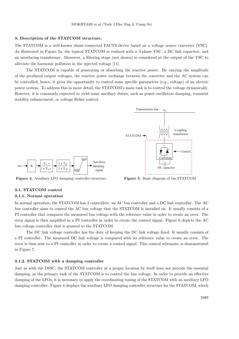
an auxiliary LFO damping controller. Figure 4 displays the auxiliary LFO damping controller structure. It is
composed of a gain block, a washout filter, and a lead-lag compensator. For the LFO auxiliary controller, ∆ω
denotes the rotor speed deviation, which is adopted as the feedback input signal, whereas other measurable
signals, such as the bus frequency and the bus voltage magnitude, have been selected in other works [3,11].
The output of the LFO damping controller is utilized to modulate the VDCref to yield the proper damping of
oscillations.
The damping controller is designed so as to provide an extra electrical torque in phase with the speed
deviation in order to enhance the damping of oscillations. The gain setting of the damping controller is adopted
so as to achieve the desired damping ratio of the electromechanical oscillations.
1688
MOKHTARI et al./Turk J Elec Eng & Comp Sci
3. Description of the STATCOM structure.
The STATCOM is a well-known shunt-connected FACTS device based on a voltage source converter (VSC).
As illustrated in Figure 5a, the typical STATCOM is realized with a 3-phase VSC, a DC link capacitor, and
an interfacing transformer. Moreover, a filtering stage (not shown) is considered at the output of the VSC to
alleviate the harmonic pollution in the injected voltage [11].
The STATCOM is capable of generating or absorbing the reactive power. By varying the amplitude
of the produced output voltages, the reactive power exchange between the converter and the AC system can
be controlled; hence, it gives the opportunity to control some specific parameters (e.g., voltage) of an electric
power system. To address this in more detail, the STATCOM’s main task is to control the voltage dynamically.
However, it is commonly expected to yield some ancillary duties, such as power oscillation damping, transient
stability enhancement, or voltage flicker control.
sT1
sT
w
w
+ sT1
sT1
2
1
+
+K
max
min
Auxiliary
damping
signal
Δω
Converter
Control
capacitorDC
Coupling
transformer
sVTransmission line
STATCOM
Figure 4. Auxiliary LFO damping controller structure. Figure 5. Basic diagram of the STATCOM.
3.1. STATCOM control
3.1.1. Normal operation
In normal operation, the STATCOM has 2 controllers: an AC bus controller and a DC link controller. The AC
bus controller aims to control the AC bus voltage that the STATCOM is installed on. It usually consists of a
PI controller that compares the measured bus voltage with the reference value in order to create an error. The
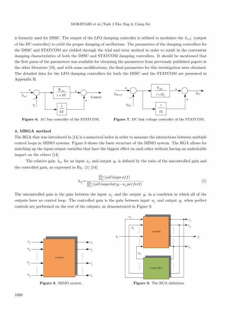
error signal is then amplified in a PI controller in order to create the control signal. Figure 6 depicts the AC
bus voltage controller that is granted to the STATCOM.
The DC link voltage controller has the duty of keeping the DC link voltage fixed. It usually consists of
a PI controller. The measured DC link voltage is compared with its reference value to create an error. The
error is then sent to a PI controller in order to create a control signal. This control schematic is demonstrated
in Figure 7.
3.1.2. STATCOM with a damping controller
Just as with the DSSC, the STATCOM controller at a proper location by itself does not provide the essential
damping, as the primary task of the STATCOM is to control the bus voltage. In order to provide an effective
damping of the LFOs, it is necessary to apply the coordinating tuning of the STATCOM with an auxiliary LFO
damping controller. Figure 4 displays the auxiliary LFO damping controller structure for the STATCOM, which
1689
MOKHTARI et al./Turk J Elec Eng & Comp Sci
is formerly used for DSSC. The output of the LFO damping controller is utilized to modulate the δref (output
of the DC controller) to yield the proper damping of oscillations. The parameters of the damping controllers for
the DSSC and STATCOM are yielded through the trial and error method in order to result in the convenient
damping characteristics of both the DSSC and STATCOM damping controllers. It should be mentioned that
the first guess of the parameters was available for obtaining the parameters from previously published papers in
the other literature [10], and with some modifications, the final parameters for this investigation were obtained.
The detailed data for the LFO damping controllers for both the DSSC and the STATCOM are presented in
Appendix B.
Vre f
V
ControlST
KAC
+1
ST
1
VDCref
VDC
11 ST
KDC
+
1
1
ST
refδ
Figure 6. AC bus controller of the STATCOM. Figure 7. DC link voltage controller of the STATCOM.
4. MRGA method
The RGA that was introduced in [14] is a numerical index in order to measure the interactions between multiple
control loops in MIMO systems. Figure 8 shows the basic structure of the MIMO system. The RGA allows for
matching up the input-output variables that have the biggest effect on each other without having an undesirable
impact on the others [14].
The relative gain λij for an input uj and output yi is defined by the ratio of the uncontrolled gain and
the controlled gain, as expressed in Eq. (1) [14]:
λij=
∂λi
∂uj|(all loops off)
∂λi
∂uj|(all loops but yi−uj perfect)
. (1)
The uncontrolled gain is the gain between the input uj and the output yi in a condition in which all of the
outputs have no control loop. The controlled gain is the gain between input uj and output yi when perfect
controls are performed on the rest of the outputs, as demonstrated in Figure 9.
system
1u
2u
ju
nu
1y
2y
jy
ny
system
1u
2u
ju
nu
1y
2y
jy
ny
controller
Figure 8. MIMO system. Figure 9. The RGA definition.
1690
MOKHTARI et al./Turk J Elec Eng & Comp Sci
If λij = 1, it means that the uncontrolled gain and controlled gain are identical. In other words, the
interaction does not affect the pairing of the input uj and the output yi . As λij is closer to unity, there are
fewer interactions in the control pair: yi−uj . The worst case occurs when λij is much greater than or much
less than unity. It means that the system is faced with serious interactions.
The RGA (n× n) for all of the relative gains, λij , which are formed from multiple control loops, can be
driven by the following equation [14]:
2RGA = G(0)⊗ (G(0)−1
)T, (2)
where G(s) is the transfer function matrix of the control system, ⊗ denotes the element-by-element multiplica-
tion of the matrices, and the superscript T stands for the transpose operation of the matrix.
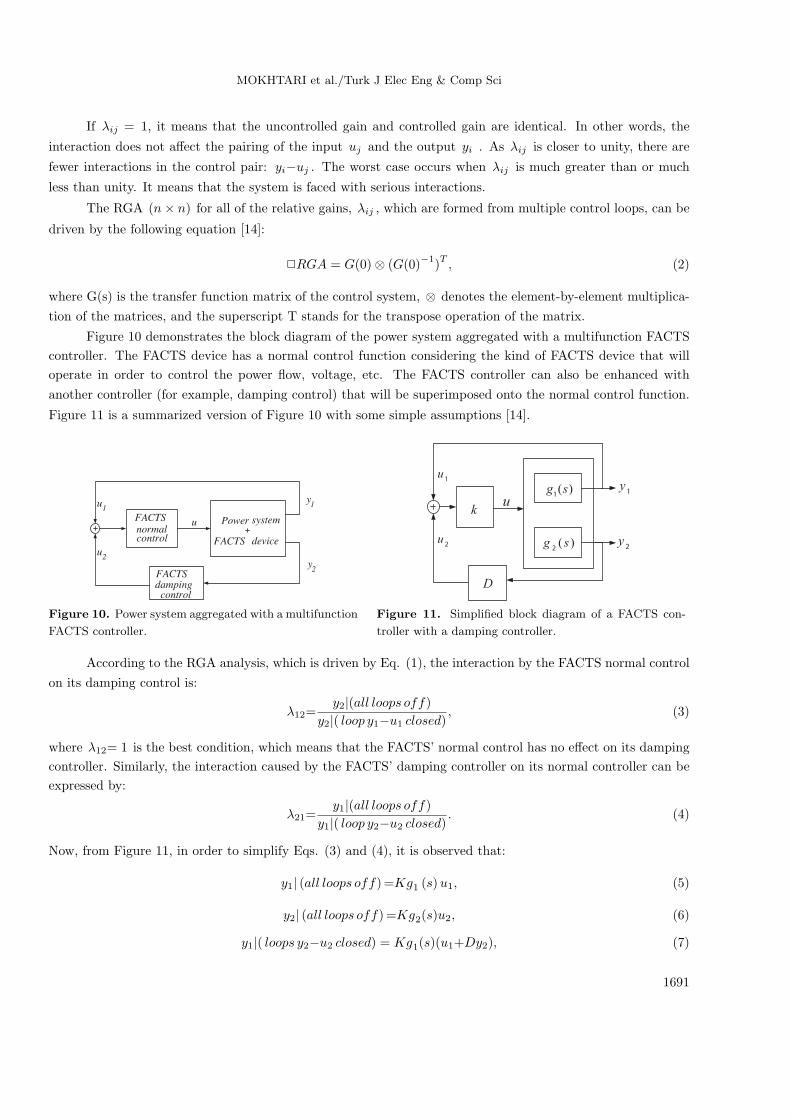
Figure 10 demonstrates the block diagram of the power system aggregated with a multifunction FACTS
controller. The FACTS device has a normal control function considering the kind of FACTS device that will
operate in order to control the power flow, voltage, etc. The FACTS controller can also be enhanced with
another controller (for example, damping control) that will be superimposed onto the normal control function.
Figure 11 is a summarized version of Figure 10 with some simple assumptions [14].
1u
2u
u
1y
2y
FACTSnormalcontrol
systemPower
FACTS device
FACTS
controldamping
1u
2u
u1y
2y
k
D
)(1sg
)(2sg
Figure 10. Power system aggregated with a multifunction
FACTS controller.
Figure 11. Simplified block diagram of a FACTS con-
troller with a damping controller.
According to the RGA analysis, which is driven by Eq. (1), the interaction by the FACTS normal control
on its damping control is:
λ12=y2|(all loops off)
y2|( loop y1−u1 closed), (3)
where λ12= 1 is the best condition, which means that the FACTS’ normal control has no effect on its damping
controller. Similarly, the interaction caused by the FACTS’ damping controller on its normal controller can be
expressed by:
λ21=y1|(all loops off)
y1|( loop y2−u2 closed). (4)
Now, from Figure 11, in order to simplify Eqs. (3) and (4), it is observed that:
y1| (all loops off)=Kg1 (s)u1, (5)
y2| (all loops off)=Kg2(s)u2, (6)
y1|( loops y2−u2 closed) = Kg1(s)(u1+Dy2), (7)
1691
MOKHTARI et al./Turk J Elec Eng & Comp Sci
y2|( loops y1−u1 closed) = Kg2(s)(u1+u2), (8)
y2|( loops y2−u2 closed) = Kg2 (s) (u1+Dy2)=Kg2(s)u1
1− kDg2(s), (9)
y1|( loops y1−u1 closed) = Kg1 (s) (u1+u2)=Kg1(s)u2
1− kg1(s), (10)
y1|( loops y2−u2 closed) = Kg1 (s)
(u1+
DKg2(s)u1
1− kDg2(s)
)=
Kg1(s)u1
1− kDg2(s). (11)
By substituting Eq. (10) into Eq. (8):
y2|( loops y1−u1 closed) = Kg2 (s)
(Kg1 (s)u2
1− kg1 (s)+u2
)=
Kg2(s)u2
1− kg1(s). (12)
Finally, from Eqs. (3), (6), and (12):
λ12= 1− kg1(s), (13)
and from Eqs. (4), (5), and (11):
λ21= 1− kDg2 (s) . (14)
The above definitions describe the MRGA that is given by Eqs. (13) and (14). For any power system, these
equations can be comprehended in order to gain the interaction between the different controllers of the power
system. This value should be taken into account when designing multifunction controllers.
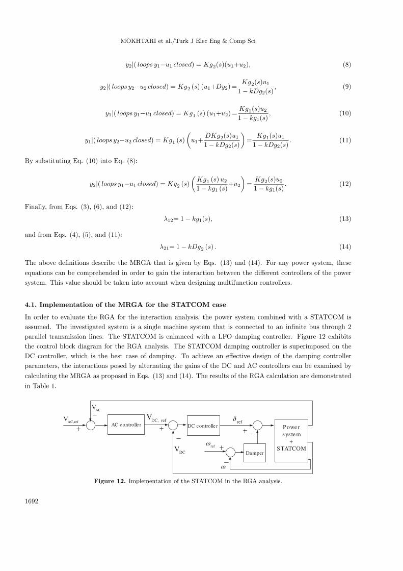
4.1. Implementation of the MRGA for the STATCOM case
In order to evaluate the RGA for the interaction analysis, the power system combined with a STATCOM is
assumed. The investigated system is a single machine system that is connected to an infinite bus through 2
parallel transmission lines. The STATCOM is enhanced with a LFO damping controller. Figure 12 exhibits
the control block diagram for the RGA analysis. The STATCOM damping controller is superimposed on the
DC controller, which is the best case of damping. To achieve an effective design of the damping controller
parameters, the interactions posed by alternating the gains of the DC and AC controllers can be examined by
calculating the MRGA as proposed in Eqs. (13) and (14). The results of the RGA calculation are demonstrated
in Table 1.
ACV
refACV
,
DCV
refDCV
, refδ
refω
ω
AC controlle r DC controlle r
Damper
Power
sys tem
+
STATCOM
Figure 12. Implementation of the STATCOM in the RGA analysis.
1692
MOKHTARI et al./Turk J Elec Eng & Comp Sci
The interactions between the different controllers shown in Figure 12 are measured by changing the gain
values of each controller in order to achieve the best gain value, as depicted in Table 1. It should be noted
that, to damp the power-system electromechanical oscillations, a damping controller is superimposed on the
DC controller of the STATCOM in order to yield the best damping performance.
Table 1. The interaction calculated by the MRGA between the STATCOM controllers.
Gain of the DC controller in Interaction caused by the DCthe STATCOM voltage controller on the AC
voltage controllerKdc = 1 1.023Kdc = 3 5.248Kdc = 6 17.854Gain of the DC controller in Interaction caused by the DCthe STATCOM voltage controller on the
damping controllerKdc = 1 1.877Kdc = 3 8.452Kdc = 6 21.076Gain of the AC controller in Interaction caused by the ACthe STATCOM voltage controller on the
damping controllerKac = 1 2.107Kac = 2 9.726Kac = 4 18.844
From Table 1, the interactions between the STATCOM DC voltage controller, AC voltage controller,
and damping controller are not significant when the gain value of each controller is set to unity. In contrast,
by increasing the gain settings of each controller, the interaction will be deteriorated. For example, if the
gain of the DC controller of the STATCOM is set to 1, the interaction caused by the DC voltage controller of
the STATCOM on its damping controller is 1.877, which is very close to unity and verifies that there is less
interaction between the DC voltage controller and the damping controller of the STATCOM. Furthermore, this
interaction is 21.076 if the gain of the DC controller in the STATCOM is set to 6, which is fairly large.
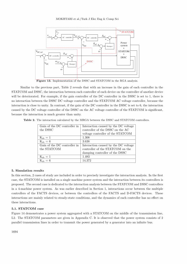
4.2. Implementation of the MRGA for the STATCOM and DSSC case
Now, consider a condition in which both the DSSC and the STATCOM are operating in a power system. In
this condition, the main duty of the DSSC is to control the power flow in the transmission line, and it can
also suppress the interarea oscillation with a supplementary damping controller. In contrast, the STATCOM is
operating to regulate the AC bus voltage, and it can also damp the local mode oscillations with an auxiliary
damping controller. Hence, if the settings of these devices are not tuned properly, the interactions will be
unavoidable. In this part, in order to evaluate the RGA for the interaction analysis, a 4-machine power system
combined with the DSSC and STATCOM is assumed [22]. Both the DSSC and the STATCOM are enhanced
with LFO damping controllers. Figure 13 exhibits the control block diagram of this case for the RGA analysis.
The DSSC and STATCOM damping controllers are superimposed on the DC controller of each device, which is
the best case of damping. To achieve an effective design of the damping controller parameters, the interactions
posed by alternating the gains of the DC and AC controllers can be examined by calculating the MRGA, as
proposed in Eqs. (13) and (14). The results of the RGA calculation are demonstrated in Table 2.
1693
MOKHTARI et al./Turk J Elec Eng & Comp Sci
ACV
refACV
,
DCV
refDCV
, refδ
refδ
ω
AC controlle r DC controlle r
Damper
DCV
refδ
refω
ω
DC co ntrolle r
refDCV ,
Damper
STATCOM
DSSC
Powersystem+
STATCOM+
DSSC
Figure 13. Implementation of the DSSC and STATCOM in the RGA analysis.
Similar to the previous part, Table 2 reveals that with an increase in the gain of each controller in the
STATCOM and DSSC, the interaction between each controller of each device on the controller of another device
will be deteriorated. For example, if the gain controller of the DC controller in the DSSC is set to 1, there is
no interaction between the DSSC DC voltage controller and the STATCOM AC voltage controller, because the
interaction is close to unity. In contrast, if the gain of the DC controller in the DSSC is set to 6, the interaction
caused by the DC voltage controller of the DSSC on the AC voltage controller of the STATCOM is significant,
because the interaction is much greater than unity.
Table 2. The interaction calculated by the MRGA between the DSSC and STATCOM controllers.
Gain of the DC controller in Interaction caused by the DC voltagethe DSSC controller of the DSSC on the AC
voltage controller of the STATCOMKdc = 1 1.308Kdc = 6 3.638Gain of the DC controller in Interaction caused by the DC voltagethe STATCOM controller of the STATCOM on the
damping controller of the DSSCKdc = 1 1.483Kdc = 6 14.372
5. Simulation results
In this section, 2 cases of study are included in order to precisely investigate the interaction analysis. In the first
case, the STATCOM is installed on a single machine power system and the interaction between its controllers is
proposed. The second case is dedicated to the interaction analysis between the STATCOM and DSSC controllers
in a 4-machine power system. As was earlier described in Section 1, interactions occur between the multiple
controllers of the FACTS devices, or between the controllers of the FACTS and D-FACTS devices. These
interactions are mainly related to steady-state conditions, and the dynamics of each controller has no effect on
these interactions.
5.1. STATCOM case
Figure 14 demonstrates a power system aggregated with a STATCOM on the middle of the transmission line,
L2. The STATCOM parameters are given in Appendix C. It is observed that the power system consists of 2
parallel transmission lines in order to transmit the power generated by a generator into an infinite bus.
1694
MOKHTARI et al./Turk J Elec Eng & Comp Sci
G1L
STATCOM
Infinite Bus25.0 L25.0 L
Fault
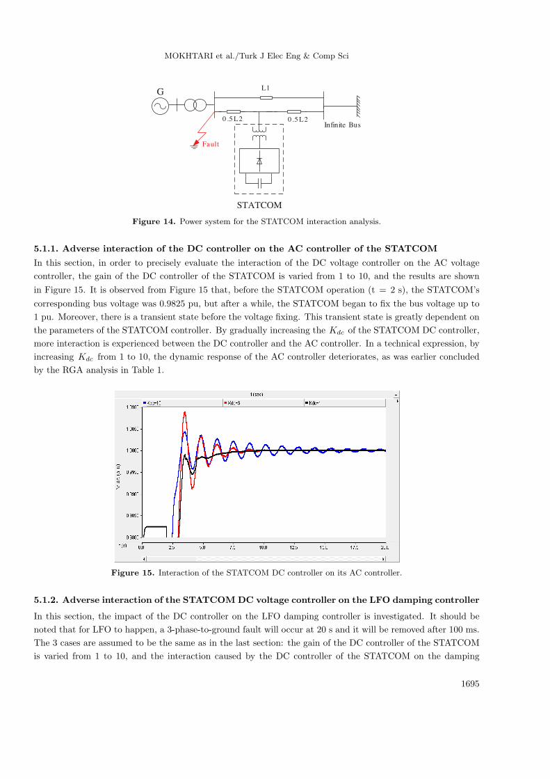
Figure 14. Power system for the STATCOM interaction analysis.
5.1.1. Adverse interaction of the DC controller on the AC controller of the STATCOM
In this section, in order to precisely evaluate the interaction of the DC voltage controller on the AC voltage
controller, the gain of the DC controller of the STATCOM is varied from 1 to 10, and the results are shown
in Figure 15. It is observed from Figure 15 that, before the STATCOM operation (t = 2 s), the STATCOM’s
corresponding bus voltage was 0.9825 pu, but after a while, the STATCOM began to fix the bus voltage up to
1 pu. Moreover, there is a transient state before the voltage fixing. This transient state is greatly dependent on
the parameters of the STATCOM controller. By gradually increasing the Kdc of the STATCOM DC controller,
more interaction is experienced between the DC controller and the AC controller. In a technical expression, by
increasing Kdc from 1 to 10, the dynamic response of the AC controller deteriorates, as was earlier concluded
by the RGA analysis in Table 1.
Figure 15. Interaction of the STATCOM DC controller on its AC controller.
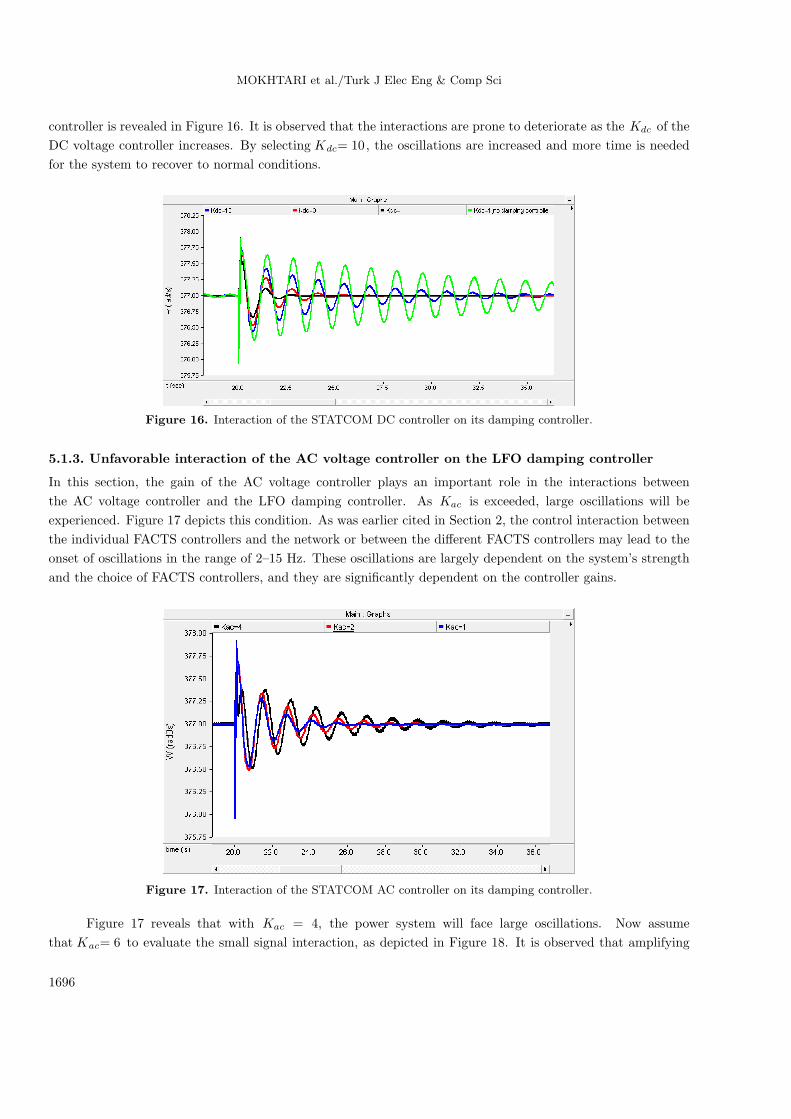
5.1.2. Adverse interaction of the STATCOM DC voltage controller on the LFO damping controller
In this section, the impact of the DC controller on the LFO damping controller is investigated. It should be
noted that for LFO to happen, a 3-phase-to-ground fault will occur at 20 s and it will be removed after 100 ms.
The 3 cases are assumed to be the same as in the last section: the gain of the DC controller of the STATCOM
is varied from 1 to 10, and the interaction caused by the DC controller of the STATCOM on the damping
1695
MOKHTARI et al./Turk J Elec Eng & Comp Sci
controller is revealed in Figure 16. It is observed that the interactions are prone to deteriorate as the Kdc of the
DC voltage controller increases. By selecting Kdc= 10, the oscillations are increased and more time is needed
for the system to recover to normal conditions.
Figure 16. Interaction of the STATCOM DC controller on its damping controller.
5.1.3. Unfavorable interaction of the AC voltage controller on the LFO damping controller
In this section, the gain of the AC voltage controller plays an important role in the interactions between
the AC voltage controller and the LFO damping controller. As Kac is exceeded, large oscillations will be
experienced. Figure 17 depicts this condition. As was earlier cited in Section 2, the control interaction between
the individual FACTS controllers and the network or between the different FACTS controllers may lead to the
onset of oscillations in the range of 2–15 Hz. These oscillations are largely dependent on the system’s strength
and the choice of FACTS controllers, and they are significantly dependent on the controller gains.
Figure 17. Interaction of the STATCOM AC controller on its damping controller.
Figure 17 reveals that with Kac = 4, the power system will face large oscillations. Now assume
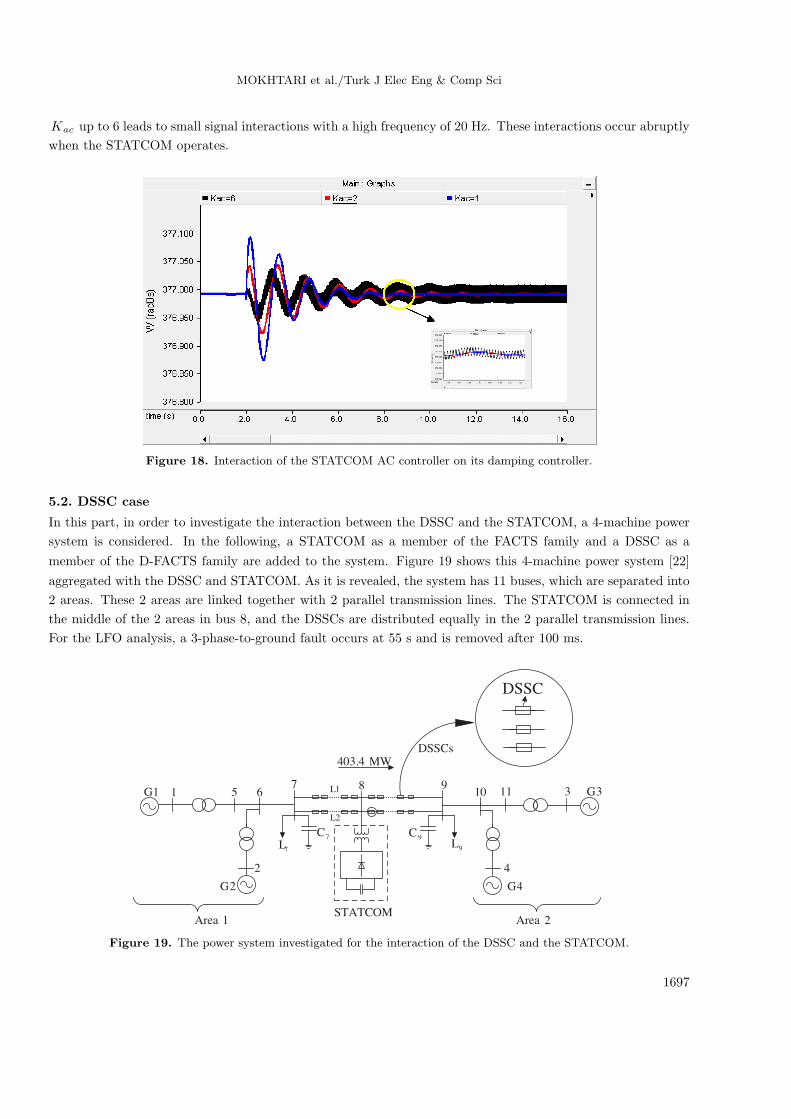
that Kac= 6 to evaluate the small signal interaction, as depicted in Figure 18. It is observed that amplifying
1696
MOKHTARI et al./Turk J Elec Eng & Comp Sci
Kac up to 6 leads to small signal interactions with a high frequency of 20 Hz. These interactions occur abruptly
when the STATCOM operates.
Figure 18. Interaction of the STATCOM AC controller on its damping controller.
5.2. DSSC case
In this part, in order to investigate the interaction between the DSSC and the STATCOM, a 4-machine power
system is considered. In the following, a STATCOM as a member of the FACTS family and a DSSC as a
member of the D-FACTS family are added to the system. Figure 19 shows this 4-machine power system [22]
aggregated with the DSSC and STATCOM. As it is revealed, the system has 11 buses, which are separated into
2 areas. These 2 areas are linked together with 2 parallel transmission lines. The STATCOM is connected in
the middle of the 2 areas in bus 8, and the DSSCs are distributed equally in the 2 parallel transmission lines.
For the LFO analysis, a 3-phase-to-ground fault occurs at 55 s and is removed after 100 ms.
1 5 61G
2
7L
7C
7 8
9L
9C
9
MW4.403
31110 3G
4
2G 4G
1L
2L
DSSCs
1Area 2Area
DSSC
STATCOM
Figure 19. The power system investigated for the interaction of the DSSC and the STATCOM.
1697
MOKHTARI et al./Turk J Elec Eng & Comp Sci
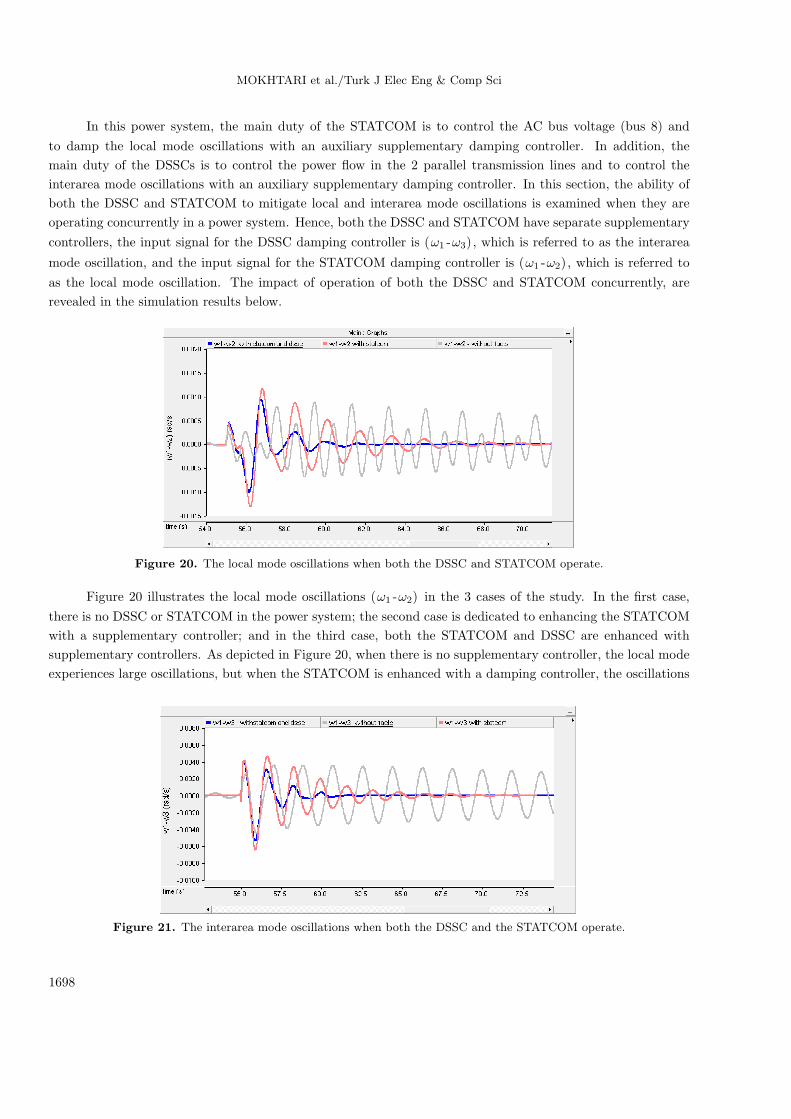
In this power system, the main duty of the STATCOM is to control the AC bus voltage (bus 8) and
to damp the local mode oscillations with an auxiliary supplementary damping controller. In addition, the
main duty of the DSSCs is to control the power flow in the 2 parallel transmission lines and to control the
interarea mode oscillations with an auxiliary supplementary damping controller. In this section, the ability of
both the DSSC and STATCOM to mitigate local and interarea mode oscillations is examined when they are
operating concurrently in a power system. Hence, both the DSSC and STATCOM have separate supplementary
controllers, the input signal for the DSSC damping controller is (ω1 -ω3), which is referred to as the interarea
mode oscillation, and the input signal for the STATCOM damping controller is (ω1 -ω2), which is referred to
as the local mode oscillation. The impact of operation of both the DSSC and STATCOM concurrently, are
revealed in the simulation results below.
Figure 20. The local mode oscillations when both the DSSC and STATCOM operate.
Figure 20 illustrates the local mode oscillations (ω1 -ω2) in the 3 cases of the study. In the first case,
there is no DSSC or STATCOM in the power system; the second case is dedicated to enhancing the STATCOM
with a supplementary controller; and in the third case, both the STATCOM and DSSC are enhanced with
supplementary controllers. As depicted in Figure 20, when there is no supplementary controller, the local mode
experiences large oscillations, but when the STATCOM is enhanced with a damping controller, the oscillations
Figure 21. The interarea mode oscillations when both the DSSC and the STATCOM operate.
1698
MOKHTARI et al./Turk J Elec Eng & Comp Sci
decrease after a short interval of time. The superior performance for the local mode damping is achieved when
both the DSSC and STATCOM are supplemented with auxiliary controllers. This verifies that operation of
both the STATCOM and DSSC in the power system provides many advantages in the dynamic stability of the
system.
Similar simulations are carried out for interarea mode oscillations in 3 cases in Figure 21. In the first
case, the system is simulated without a DSSC or STATCOM; in the second case, the DSSCs are enhanced with
a supplementary controller; and the third case is dedicated to the operation of the DSSCs and STATCOM with
supplementary damping controllers. It is revealed that the worst case is when there is no DSSC or STATCOM.
In this case, large oscillations will be experienced for the interarea mode. Moreover, when the DSSCs are
enhanced with a damping controller, the oscillations will be suppressed after a few seconds. Furthermore, the
oscillations are damped greatly when both the DSSC and STATCOM are enhanced with damping controllers.
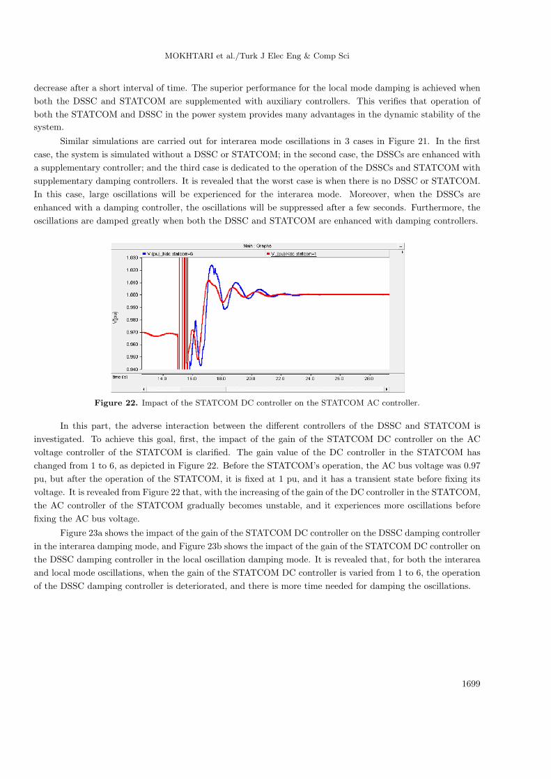
Figure 22. Impact of the STATCOM DC controller on the STATCOM AC controller.
In this part, the adverse interaction between the different controllers of the DSSC and STATCOM is
investigated. To achieve this goal, first, the impact of the gain of the STATCOM DC controller on the AC
voltage controller of the STATCOM is clarified. The gain value of the DC controller in the STATCOM has
changed from 1 to 6, as depicted in Figure 22. Before the STATCOM’s operation, the AC bus voltage was 0.97
pu, but after the operation of the STATCOM, it is fixed at 1 pu, and it has a transient state before fixing its
voltage. It is revealed from Figure 22 that, with the increasing of the gain of the DC controller in the STATCOM,
the AC controller of the STATCOM gradually becomes unstable, and it experiences more oscillations before
fixing the AC bus voltage.
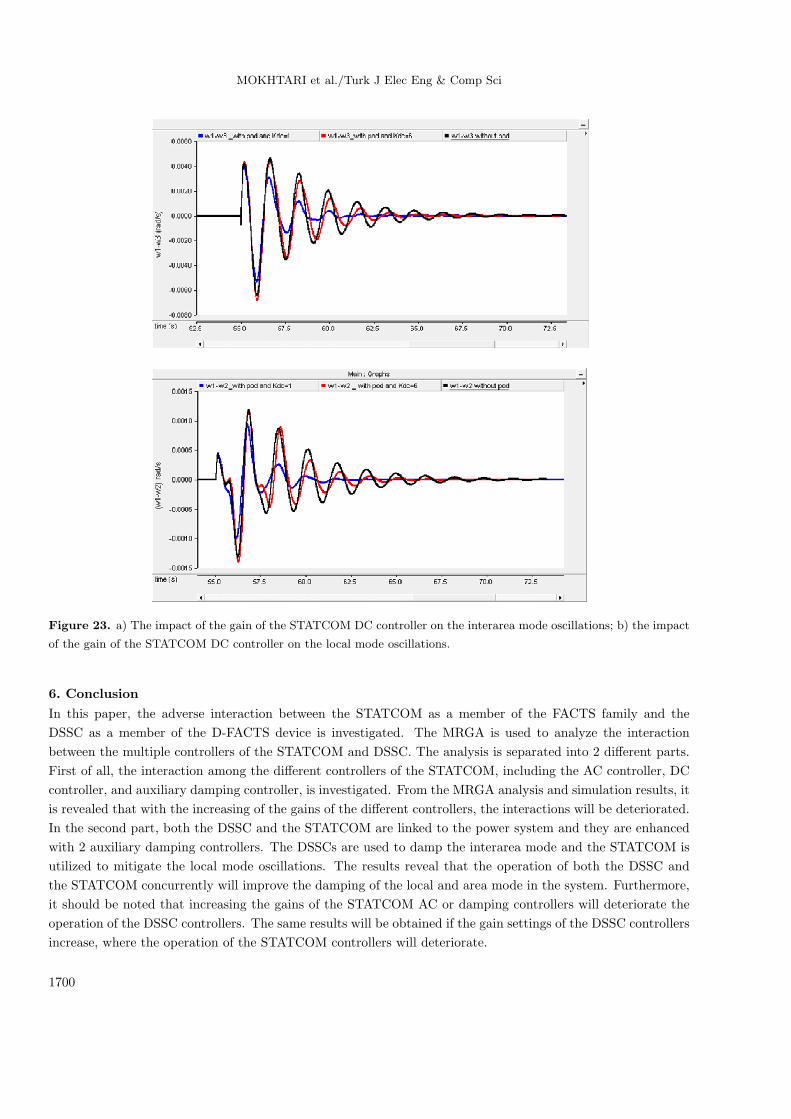
Figure 23a shows the impact of the gain of the STATCOM DC controller on the DSSC damping controller
in the interarea damping mode, and Figure 23b shows the impact of the gain of the STATCOM DC controller on
the DSSC damping controller in the local oscillation damping mode. It is revealed that, for both the interarea
and local mode oscillations, when the gain of the STATCOM DC controller is varied from 1 to 6, the operation
of the DSSC damping controller is deteriorated, and there is more time needed for damping the oscillations.
1699
MOKHTARI et al./Turk J Elec Eng & Comp Sci
Figure 23. a) The impact of the gain of the STATCOM DC controller on the interarea mode oscillations; b) the impact
of the gain of the STATCOM DC controller on the local mode oscillations.
6. Conclusion
In this paper, the adverse interaction between the STATCOM as a member of the FACTS family and the
DSSC as a member of the D-FACTS device is investigated. The MRGA is used to analyze the interaction
between the multiple controllers of the STATCOM and DSSC. The analysis is separated into 2 different parts.
First of all, the interaction among the different controllers of the STATCOM, including the AC controller, DC
controller, and auxiliary damping controller, is investigated. From the MRGA analysis and simulation results, it
is revealed that with the increasing of the gains of the different controllers, the interactions will be deteriorated.
In the second part, both the DSSC and the STATCOM are linked to the power system and they are enhanced
with 2 auxiliary damping controllers. The DSSCs are used to damp the interarea mode and the STATCOM is
utilized to mitigate the local mode oscillations. The results reveal that the operation of both the DSSC and
the STATCOM concurrently will improve the damping of the local and area mode in the system. Furthermore,
it should be noted that increasing the gains of the STATCOM AC or damping controllers will deteriorate the
operation of the DSSC controllers. The same results will be obtained if the gain settings of the DSSC controllers
increase, where the operation of the STATCOM controllers will deteriorate.
1700
MOKHTARI et al./Turk J Elec Eng & Comp Sci
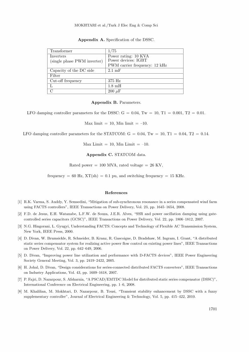
Appendix A. Specification of the DSSC.
Transformer 1/75Inverters(single phase PWM inverter)
Power rating: 10 KVAPower devices: IGBTPWM carrier frequency: 12 kHz
Capacity of the DC side 2.1 mFFilterCut-off frequency 375 HzL 1.8 mHC 200 µF
Appendix B. Parameters.
LFO damping controller parameters for the DSSC: G = 0.04, Tw = 10, T1 = 0.001, T2 = 0.01.
Max limit = 10, Min limit = –10.
LFO damping controller parameters for the STATCOM: G = 0.04, Tw = 10, T1 = 0.04, T2 = 0.14.
Max Limit = 10, Min Limit = –10.
Appendix C. STATCOM data.
Rated power = 100 MVA, rated voltage = 26 KV,
frequency = 60 Hz, XT(sh) = 0.1 pu, and switching frequency = 15 KHz.
References
[1] R.K. Varma, S. Auddy, Y. Semsedini, “Mitigation of sub-synchronous resonance in a series compensated wind farm
using FACTS controllers”, IEEE Transactions on Power Delivery, Vol. 23, pp. 1645–1654, 2008.
[2] F.D. de Jesus, E.H. Watanabe, L.F.W. de Souza, J.E.R. Alves, “SSR and power oscillation damping using gate-
controlled series capacitors (GCSC)”, IEEE Transactions on Power Delivery, Vol. 22, pp. 1806–1812, 2007.
[3] N.G. Hingorani, L. Gyugyi, Understanding FACTS: Concepts and Technology of Flexible AC Transmission System,
New York, IEEE Press, 2000.
[4] D. Divan, W. Brumsickle, R. Schneider, B. Kranz, R. Gascoigne, D. Bradshaw, M. Ingram, I. Grant, “A distributed
static series compensator system for realizing active power flow control on existing power lines”, IEEE Transactions
on Power Delivery, Vol. 22, pp. 642–649, 2006.
[5] D. Divan, “Improving power line utilization and performance with D-FACTS devices”, IEEE Power Engineering
Society General Meeting, Vol. 3, pp. 2419–2422, 2005.
[6] H. Johal, D. Divan, “Design considerations for series-connected distributed FACTS converters”, IEEE Transactions
on Industry Applications, Vol. 43, pp. 1609–1618, 2007.
[7] P. Fajri, D. Nazarpour, S. Afsharnia, “A PSCAD/EMTDCModel for distributed static series compensator (DSSC)”,
International Conference on Electrical Engineering, pp. 1–6, 2008.
[8] M. Khalilian, M. Mokhtari, D. Nazarpour, B. Tousi, “Transient stability enhancement by DSSC with a fuzzy
supplementary controller”, Journal of Electrical Engineering & Technology, Vol. 5, pp. 415–422, 2010.
1701
MOKHTARI et al./Turk J Elec Eng & Comp Sci
[9] M. Mokhtari, M. Khalilian, D. Nazarpour, “Damping of low frequency oscillations in power system with distributed
static series compensator (DSSC)”, International Review on Modeling and Simulation, Vol. 2, pp. 507–512, 2009.
[10] M. Khalilian, M. Mokhtari, S. Golshannavaz, D. Nazarpour, “Distributed static series compensator (DSSC) for
sub-synchronous resonance alleviation and power oscillation damping”, European Transactions on Electrical Power,
Vol. 22, pp. 589–600, 2011.
[11] R.M. Mathur, R.K. Varma, Thyristor-Based FACTS Controllers for Electrical Transmission Systems, New York,
IEEE Press and Wiley Interscience, 2002.
[12] H.F. Wang, “Interactions and co-ordination of multiple-function FACTS controllers”, European Transactions on
Electrical Power, Vol. 11, pp. 1–15, 2001.
[13] L. Zhang, P.X. Zhang, H.F. Wang, Z. Chen, W. Du, Y.J. Cao, S.J. Chen, “Interaction assessment of FACTS control
by RGA for the effective design of FACTS damping controllers”, IET Generation, Transmission & Distribution,
Vol. 153, pp. 610–615, 2006.
[14] H.F. Wang, M. Jazaeri, Y.J. Cao, “Analysis of control conflict between UPFC multiple control functions and their
interaction indicator”, International Journal of Control Automation and Systems, Vol. 3, pp. 315–321, 2005.
[15] S. Ammari, Y. Besanger, N. Hadjsaid, D. Georges, “Robust solutions for the interaction phenomena between
dynamic loads and FACTS controllers”, IEEE Power Engineering Society Summer Meeting, Vol. 1, pp. 401–406,
2000.
[16] L. Xianzhang, N. Edwin, Lerch, D. Povh, “Optimization and coordination of damping controls for improving system
dynamic performance”, IEEE Transactions on Power Systems, Vol. 16, pp. 473–480, 2001.
[17] L. Jun, T. Guangfu, L. Xingyuan, “Interaction analysis and coordination control between SSSC and SVC”,
International Conference on Power System Technology, pp. 1–9, 2006.
[18] T. Nguyen, R. Gianto, “Optimal design for control coordination of power system stabilizers and flexible alter-
nating current transmission system devices with controller saturation limits”, IET Generation, Transmission &
Distribution, Vol. 4, pp. 1028–1043, 2010.
[19] D. Divan, “Distributed intelligent power networks - a new concept for improving T&D system utilization and
performance”, IEEE Transmission and Distribution Conference, pp. 1–6, 2004.
[20] D.J. Marihart, “Communications technology guidelines for EMS/SCADA systems”, IEEE Transactions on Power
Delivery, Vol. 16, pp. 181–188, 2001.
[21] M. Rauls, “Analysis and design of high frequency co-axial winding transformers”, MSc, University of Wisconsin -
Madison, USA, 1992.
[22] P. Kundur, Power System Stability and Control, New York, McGraw-Hill, 1994.
1702