Embed Size (px)
Citation preview

692 IEEE TRANSACTIONS ON SMART GRID, VOL. 3, NO. 2, JUNE 2012
Inter-Domain Analysis of Smart Grid DomainDependencies Using Domain-Link Matrices
Husam Suleiman, Khaja Altaf Ahmed, Nauman Zafar, Emine Phillips, Davor Svetinovic, and Olivier L. de Weck
Abstract—Developers of the smart grid have proposed a numberof independent smart grid architectures. This has resulted in alack of common vision and understanding of the common smartgrid reference architecture. In particular, there is a lack of under-standing of various inter-domain relationships and dependenciesamong technical and business domains within the smart grid. Thispaper presents an inter-domain analysis of these complex depen-dencies among the business and technical domains of the smartgrid using Domain-LinkMatrices. This inter-domain analysis clar-ifies and bridges the technical architecture to the business architec-ture. The aim is to maintain the rationale for the solutions devel-oped in the technical domains in order to solve the problems of thebusiness domains; and, as such, this analysis contributes towardfurther development and refinement of the smart grid referencearchitecture.
Index Terms—Smart grid architecture, smart grid domain map-pings.
I. INTRODUCTION
R EFERENCE architectures are used to facilitate a sharedunderstanding across multiple systems, products, and do-
mains by using the architectural descriptions [1]. For example,Microsoft published Smart Energy Reference Architecture(SERA) [2], which was developed as a specification of the Na-tional Institute of Standards and Technology (NIST) Roadmap[3] to address the main issues of the smart grid energy initiativeby using Microsoft products and technologies. Generally, a ref-erence architecture is strongly linked to a company’s mission,vision, and strategy. Thus, the existing reference architecturesvary in nature and format. The findings of the System Architec-ture Forum [1] on reference architectures show that referencearchitectures should address three issues: technical architec-ture, business architecture, and customer context. These threecomponents of a reference architecture should be accompaniedby the links showing their inter-relationships. Linking businessarchitecture to technical architecture can help increase theunderstanding of a system from both technical and businessperspectives. Without this process of linking the domains, thebusiness questions may remain unanswered, or there would be
Manuscript received February 07, 2011; revised August 08, 2011 and October31, 2011; accepted November 07, 2011. Date of publication February 13, 2012;date of current version May 21, 2012. Paper no. TSG-00031-2011.H. Suleiman, K. A. Ahmed, N. Zafar, E. Phillips, and D. Svetinovic are
with the Computing and Information Science Program, Masdar Institute ofScience and Technology, Abu Dhabi, UAE (e-mail: [email protected];[email protected]; [email protected]; [email protected];[email protected]).O. L. de Weck is with the Department of Aeronautics and Astronautics and
Engineering Systems Division, Massachusetts Institute of Technology (MIT),Cambridge, MA 02139 USA (e-mail: [email protected]).Color versions of one or more of the figures in this paper are available online
at http://ieeexplore.ieee.org.Digital Object Identifier 10.1109/TSG.2011.2176151
no record of how a certain business concern is addressed by atechnical solution.In this paper, we use inter-domain analysis in order to analyze
and elaborate the complex relationships among various tech-nical and business domains of the proposed smart grid referencearchitectures. Inter-domain analysis provides the means to an-alyze and explore relationships among various domains withina system or among different systems. The concept of inter-do-main analysis is taken from NIST which is actively involvedin exploring the smart grid domains and relationships amongstthem [4]. We explore vertical and horizontal domains relatedto the business and technical aspects of the smart grid. Domainanalysis plays an important role in systems engineering. Domainanalysis is a method used to analytically and consistently iden-tify, capture, and organize information in order to specify ob-jects and operations of a class of similar systems in a particularproblem domain. The main objective is to make all domain in-formation readily available to develop a system [5], [6]. Domainanalysis is also used to discover and describe commonality andvariability within a problem domain [7]. In systems engineeringterminology, vertical domains are the domains across systemswhile horizontal domains are the domains within a system [8].We identify and capture the relationships among these
domains using Domain-Link Matrices (DLM). We analyzethe complex relationships across the business and technicaldomains of the smart grid reference architecture, which meetsthe vertical domain aspect of systems engineering. We analyzevarious sub-domains of a particular domain. In the horizontaldomain, we decompose customer domain into AdvancedMetering Infrastructure (AMI), customer appliances, etc. Like-wise, in the vertical domain, we decompose integration domaininto process integration, entity integration, and portal integra-tion. At the same time, we perform inter-domain analysis byidentifying and describing the relationships among the verticaland horizontal domains.Section II provides background and related work about the
reference architecture, SERA, and the smart grid energy initia-tive in order to provide the context for this study. Section IIIprovides an overview of the business aspects of the smart grid.Section IV explains the approach used in this study for linkingtechnical domains to business domains. Section V discusses theresults of our study. Section VI summarizes the study, suggestsimprovements, and discusses the future work.
II. BACKGROUND AND RELATED WORK
The definition and usage of reference architectures are stillnot standardized since they are used for slightly different pur-poses by different enterprises. For example, Sun’s reference ar-chitecture [9] is comprised of a documented multi-tiered archi-
1949-3053/$31.00 © 2012 IEEE

SULEIMAN et al.: INTER-DOMAIN ANALYSIS OF SMART GRID DOMAIN DEPENDENCIES USING DOMAIN-LINK MATRICES 693
tecture, recommended technology products from Sun and othervendors, as well as, architecture, sizing, and implementationguidelines. On the other hand, Burton Group’s reference archi-tecture [10] is built as a proprietary knowledgebase built on theirresearch and industrial experience from past consulting projects.The Burton Group’s reference architecture outlines the com-pany’s foundation principles together with technical positionsand templates to guide the decision making process in formu-lating strategic decisions.The content of both Sun’s and Burton Research Group’s refer-
ence architectures is not prepared with a specific customer con-text in mind. Instead, these reference architectures are specifiedbased on the business solutions that the respective companies im-plemented, and to present these products’ use in different con-texts.Therearealsoreferencearchitecturespublishedforapartic-ular domain. For example, Hassan andHolt introduced referencearchitecture for web servers in [11] where they define the funda-mental components and their relationships in this domain.Whilederiving thereferencearchitecture, theyusedconceptualandcon-crete architectures of already existing web servers. Thus, unlikereferencearchitecturespreparedbyenterprises, thereisnorecom-mendationas towhich toolshouldbeusedasapartofawebserver.Instead, the focus is on the domain knowledge and the commonstructure between the concrete architectures.Cloutier et al. [1] discuss two reference architectures: one
for Space Data Systems and another one acting as the Informa-tion Technology Security Architecture for the State of Arizona.These studies are both research-oriented in the sense that theydo not favor one enterprise; at the same time, they suggest theuse of various standards in the realization of certain architec-tural structures.Despite the characteristic differences, all these reference ar-
chitectures aim to address the problem of increased complexity,scope, and size of the systems which need extra care due to lim-itations on the cost, schedule, and adaptation to new technolo-gies. The last couple of decades introduced many distributedsystems which are developed at multiple locations by severalvendors across multiple organizations. Thus, the necessity toadapt to this new way of systems development while addressingthe aforementioned problems highlights the need for referencearchitectures.Cloutier et al. [1] outline the objectives of reference architec-
ture under five main categories:• providing a common lexicon, taxonomy, and an architec-tural vision for a given context;
• effective creation of products and product lines achievinginteroperability among several different and evolving sys-tems;
• elaboration of mission, vision, and strategy (for enter-prises); and
• inking past and future (especially in the context of legacysystems).
With these objectives in mind, the contents of reference ar-chitecture should include customer context, business architec-ture, and technical architecture. The customer context providesthe knowledge domain for the problem under investigation. Thebusiness architecture explains the problem with its relevance tothe particular business domain(s). Finally, the technical archi-tecture presents the technical solutions for each requirement in
the problem domain. The three sections to be included in refer-ence architecture have a distinct nature which may seem mutu-ally exclusive. In fact, the sole link between them is generallythe requirements derived from the problem specification in aproduct independent manner.Thus, it is important to maintain the links among customer
context, business architecture, and technical architecturethrough a set of requirements of the system under investigation.This paper specifically focuses on this aspect of referencearchitectures, i.e., bridging the technical architecture to thebusiness architecture in order to maintain the rationale for thesolutions proposed in technical domain to solve the problemsof business domain.The term smart grid refers to the modernization of the
electricity delivery system so it monitors, protects, and au-tomatically optimizes the operation of its interconnectedelements from the central and distributed generators throughthe high-voltage network and distribution system, to industrialusers and Building/Home Automation Systems (B/HASs),to energy storage installations, and to end-use consumersand their thermostats, electric vehicles, appliances, and otherhousehold devices [4]. The smart grid has many characteristicswhich enable it to monitor and control the operations of theunderlying power grid. These characteristics are self healingand adaptive, integration with consumers, enhancing cybersecurity, improving quality of power, interaction with energymarkets, etc. The self healing characteristic is achieved byemploying multi agents in the smart grid to enable the au-tonomous operation of the smart grid. It helps in acquiringdata, executing decision support, controling the power flow,etc. Also, smart grid security protocols can help in deterring,preventing, and detecting internal or external attacks [12].The structure of the smart grid is generally composed of thefollowing domains: bulk generation, transmission, distribution,customer, service provider, markets, and operations domains.All of these domains communicate with each other usingphysical (electrical) and logical (communication) interfaces.Electrical and communication interfaces are available amongcomponents of each domains as well [4].The smart grid Interoperability Standards Roadmap was
originally prepared by the Electric Power Research Insti-tute (EPRI) as a report to NIST [3]. NIST published a revisedversion of this document in 2010 [4]. This document aims to de-scribe the high-level smart grid reference architecture togetherwith current status, issues, and priorities for interoperabilitystandards development in order to build consensus for theInterim Roadmap among the various smart grid stakeholders.The model described in this document is now known as NISTSmart Grid Conceptual Model which is also recognized by theInstitute of Electrical and Electronics Engineers (IEEE) [13].While the NIST Roadmap focuses on the problem domain,
the documents published by enterprises generally focus on thesolution domain, and propose the usage of their products to ad-dress the concerns in various parts of the smart grid. The SERAdocument is one of these efforts which aims to reflect the tech-nological concerns for the smart grid and outlines the Microsoftproducts to address some of these concerns [2]. The SERA ex-amines the smart grid from a technical point of view and dividesthe technical domain into six areas of interest together with the

694 IEEE TRANSACTIONS ON SMART GRID, VOL. 3, NO. 2, JUNE 2012
Fig. 1. Smart grid business aspects overview.
definition of a codified approach. These areas are listed as userexperience, collaboration, information, integration, applicationarchitecture, and security [2]. The user experience domain dis-cusses the necessity of providing users with access to informa-tion and services, and which they should be able to visualize,analyze, report, and calculate certain information depending ontheir role in the smart grid lifecycle. The collaboration domainoutlines the formats in which the different actors of the smartgrid collaborate. The information domain describes the man-agement of data within the system, and categorizes the kind ofinformation that it deals with, in addition to the used standards.The integration domain lists the kind of applications within thesmart grid which may require integration with each other, anddiscusses various proprietary solutions within this context. Theapplication architecture domain emphasizes the areas that needextra attention in software architecture design. Finally, the se-curity domain briefly mentions the need for a well-establishedsecurity framework.
III. SMART GRID BUSINESS ASPECTS OVERVIEW
The domain model presented in this paper covers the high-level business aspects of the smart grid. We do not deal directlywith low-level business details such as the financial matters,costs, and revenue streams for the smart grid. The domainmodel
presented is taken from the NIST Roadmap [4] and consists ofseven business domains: bulk generation, transmission, distri-bution, operations, markets, customer, and service provider do-mains. These domains represent the core of the smart grid busi-ness aspects.The business model of the smart grid is mainly driven by
the utility companies, service providers, independent sellers,and buyers of electricity and customers. The utility companiesdeal with the bulk generation, transmission, and distributiondomains, and enable the delivery of electricity to the customers.The service providers provide various services to the utilitycompanies and customers such as maintenance, installation,repairing, monitoring, and customer support services. Theindependent sellers and buyers of electricity operate in themarkets domain and engage in the electricity business with theutility companies. Customers are the main source of revenuein the smart grid. Customers in the smart grid do not only con-sume electricity from the smart grid but also contribute to it byproducing electricity (i.e., customers are “prosumers”). Thesesources of distributed generation by the customers includethe renewable sources such as the solar panels installed at thecustomers’ rooftops.Fig. 1 gives an overview of the business perspective of the
smart grid with respect to the domains presented in this paper.

SULEIMAN et al.: INTER-DOMAIN ANALYSIS OF SMART GRID DOMAIN DEPENDENCIES USING DOMAIN-LINK MATRICES 695
Fig. 2. First-level smart grid system diagram.
With these two different perspectives of the smart grid inmind—one technical and one business—the next section ex-plains the approach followed in this paper.
IV. RESEARCH METHOD
The approach we adopted in this case study is an inter-do-main analysis from the systems engineering perspective. Sys-tems engineering techniques and concepts provide the guide-lines and the resources for the successful implementation ofcomplex systems of systems (formed by the integration of var-ious systems), such as the smart grid. Systems engineering isan inter-disciplinary approach which enables the integration ofvarious domains within the system in such a way to accomplishthe successful development and deployment of a system. For thesuccessful integration and deployment of the various domains,the relationships or the mappings among the domains should beidentified and specified.Inter-domain analysis provides the means of identifying and
capturing relationships among the various domains within asystem. In this paper, we identify, capture, and analyze thedetailed mappings among the business and technical domainsof the smart grid. The technical domains are taken from theSERA document and business domains are taken from theNIST Smart Grid Conceptual Model. Inter-domain analysis isperformed using the background domain knowledge obtainedfrom peer-reviewed scientific publications. We identify andcapture the relationships among business and technical domainsusing the background domain knowledge.In our approach, the complex relationships across the busi-
ness and technical domains of the smart grid, which form thevertical domain aspect in systems engineering, are analyzed.Wemap the domains of the NIST Smart Grid Conceptual Model
to the domains of the SERA using DLMs. A DLM is a ma-trix which maps the horizontal domain to the vertical domain.Each crossing point represents the relationships between thelinked sub-domains. Each in this matrix shows the presenceof a link between the respective domains and these links are cre-ated based on the indicators which suggest that a certain tech-nical concept is required to solve a particular business problem.These indicators can be viewed as a rationale stating the rela-tionship between a technical domain and a business domain. Werecord these indicators in a DLM as a proof of the relation be-tween these domains. Market domain analysis is covered in ourprevious publication [14], and as such, we do not discuss themarket domain here, but we include it in our tables for com-pleteness purpose.To populate DLM, each vertical sub-domain is selected and
its relationship with each horizontal sub-domain is analyzed.The relationship between each vertical sub-domain is estab-lished with each horizontal sub-domain if the vertical sub-do-main makes use of the particular horizontal sub-domain. Thisusage is determined from authentic data sources such as peer-re-viewed research publications and technical reports from stan-dardization organizations such as the NIST. Thus, a particularin the DLM indicates that a particular horizontal sub-domain
has a relationship with the corresponding vertical sub-domain.
V. RESULTS
We analyzed the domains listed in NIST Smart Grid Con-ceptual Model as the business domains, and the domains inthe SERA document as technical domains. The NIST SmartGrid Conceptual Model consists of seven business domains:bulk generation, transmission, distribution, customer, serviceprovider, markets, and operations [4], as shown in Fig. 2. Thedecomposition of these seven business domains is shown in

696 IEEE TRANSACTIONS ON SMART GRID, VOL. 3, NO. 2, JUNE 2012
Fig. 3. Second-level smart grid system diagram.
Fig. 3. The diagrams for each domain show only the communi-cation interface (not the electrical interface) of each smart grid’sdomain. The bulk generation domain, shown in Fig. 4, com-prises both renewable and non-renewable energy sources. Thetransmission domain, shown in Fig. 5, interacts with the bulktransfer of electrical power from generation sources to distribu-tion stations through multiple substations. The distribution do-main, shown in Fig. 6, is responsible for transporting the elec-tricity from transmission domain to customer domain by usingelectrical interfaces. The customer domain, shown in Fig. 7,consists of residential, commercial, and industrial customers aswell as distributed storage devices such as electric vehicles.The service provider domain, shown in Fig. 8, performs busi-ness-process-related services for power system producers, dis-tributors, and customers.Markets domain, shown in Fig. 9, dealswith the pricing issues, balance supply, and demand within the
power system. Finally, the operations domain, shown in Fig. 10,ensures the smooth operation of the power system.Each diagram is specified using SystemsModeling Language
(SysML). The domain hierarchy used in these diagrams consistsof the top-level system entity, domains, sub-domains, and com-ponents. A system consists of domains. A domain consists ofsub-domains or components. A sub-domain is a domain that isa part of a domain rather than of a system directly. Actors andinterfaces are particular types of components. For example, thecustomer domain has three sub-domains which contain compo-nents, actors, and interfaces to exchange the energy-related in-formation. Some other domains, such as the bulk generation do-main, have components, actors, and an interface without havingsub-domains.The first-level smart grid system diagram in Fig. 2 shows
the high-level interconnection among the domains of the smart

SULEIMAN et al.: INTER-DOMAIN ANALYSIS OF SMART GRID DOMAIN DEPENDENCIES USING DOMAIN-LINK MATRICES 697
Fig. 4. Third-level bulk generation domain diagram.
grid, without showing the components structure of each domain.The secure communication interface is a logical interface, whichdoes not represent a physical interface, but connects the sub-do-mains of the smart grid with each other. This communication in-terface is used to exchange energy-related information amongthe domains. The logical interface in our diagrams is a bi-di-rectional connection. The second-level smart grid system dia-gram in Fig. 3 shows the communications among the domainsand the sub-domains and components inside each domain. Allthe sub-domains of the smart grid use the communication in-terface. Each sub-domain consists of its own components. Thethird-level diagrams present the intra-communication amongthe components of each domain, e.g., bulk generation, transmis-sion, distribution, customer domains, etc.
A. Linking Smart Grid Business Domains to InformationTechnical Domain
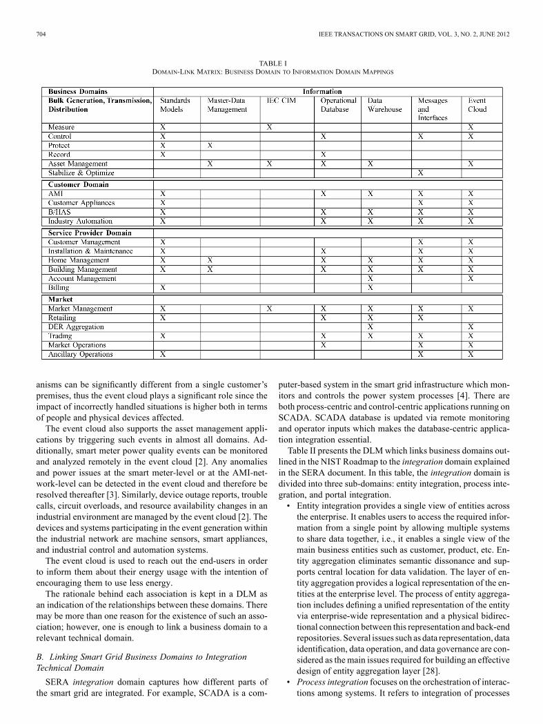
SERA information domain captures various forms of dataincluding logical models and physical models which are usedto describe database schemas, message structure, and interfacedefinitions [3]. In the smart grid, many different systems, appli-cations, and sources of information are used due to the complexnature of the electricity infrastructure and the relevant businessprocesses.Table I presents the DLM that links business domains speci-
fied in the NIST Roadmap to the information domain explainedin SERA document. We try to identify all links across thebusiness and technical domains. If there is a component inthe information domain used within the customer domain thenwe represent such link using an in the corresponding cellof the DLM. As explained in the research method section,the linkage is created if a particular business sub-domain uses
the technical sub-domain. The information domain consists ofeight sub-domains: Standards Models, Metadata Management,Master-Data Management, International ElectrotechnicalCommission (IEC) Common Information Model (CIM), Oper-ational Database, Data Warehouse, Messages and Interfaces,and Event Cloud. The links among these technical domainsand the business domains are established according to theinformation provided in the NIST Roadmap [3] and the SERAdocument [2] together with other supporting documents. Thetechnical domains together with the associated links are ex-plained in the following sub-sections.1) Standards Models: The smart grid requires a large amount
of diverse information to be managed, analyzed, and distributedin an efficient and effective manner. The format of this infor-mation flow in the system should be modeled carefully in orderto maintain interoperability of the components which are ex-pected to work together or simultaneously. These informationmodels are generally defined and documented by the industrystandards or system vendors. The SERA document [2] providesa graph of logical relationships among various smart grid stan-dards which are proposed by NIST for use within the smartgrid Interoperability Standards Framework [2], [3]. These stan-dards include, but are not limited to, AMI-Security (AMI-SEC)system security requirements, American National Standards In-stitute (ANSI) specification ANSI C12.19/MC12197 (revenuemetering informationmodel), IEC standards such as IEC 61850,IEC 61968/61970, IEEE standards such as IEEE 1547, IEEE1588, etc. Each standard serves a specific purpose, and someof the standards are series with multiple parts. In the rest ofthis subsection, the DLM for the information domain, shownin Table I, is analyzed in terms of links among the business do-mains and standards models.

698 IEEE TRANSACTIONS ON SMART GRID, VOL. 3, NO. 2, JUNE 2012
Fig. 5. Third-level transmission domain diagram.
The links betweenmeasurement or recording applications andstandards model can be explained in the context of Wide AreaMeasurement System (WAMS) [9]. WAMS consists of PhasorMeasurementUnits (PMUs) located in the stationsand in thecon-trol systems which reside in the dispatching centers. WAMS canmeasure thesmartmeterdata in thescaleofmilliseconds [9], [10].The need for a uniform informationmodel is required to facilitateinformation sharing betweenWAMSand other applications suchas EnergyManagement System (EMS) and Supervisory Controland Data Acquisition (SCADA) [9]. This necessitates the usageof standards models in the development of measurement andrecording applications. For example, IEC 61970 standard is usedto describe Application Programming Interface (API) for EMS,IEC 61970-303 standard is used to describe the CIM of SCADA,and IEC 61968 standard is used to describe Interface ReferenceModel (IRM) for Distribution Management System (DMS) inthe distribution level in the smart grid [9], thus explaining therelevant links in DLM shown in Table I.In the bulk generation, transmission, and distribution do-
mains, IEC 60870-6/Telecontrol Application Service Element2 (TASE.2) standard is relevant since it is used for data com-munication over Wide Area Network (WAN) among utilitycontrol centers, regional centers, power pools, and non-utilitygenerators, which explains the use of standards models in con-trol applications embedded in these physical devices. Anotherexample of such a standard is IEEE 1547.3, which is a guidefor not only monitoring and exchanging information, but alsofor controlling the distributed energy resources [2].Finally, for protection applications in distribution and trans-
mission levels, IEC 61850 is recommended in the context ofsubstation protection, which justifies the link in Table I [2].
As for the customer domain, customer appliances need tocommunicate with each other and exchange information fora variety of purposes, e.g., the load control device controlsthe appliances connecting to it for managing events like loadreduction, outage management, demand side management, etc[3]. To enable such communication in a secure way, there existstandards and protocols1 such as Zigbee, Homeplug, OpenHome Area Network (OpenHAN), etc. ZigBee and OpenHANare the examples of wireless protocols among the appliances,and Homeplug is an example of a wired protocol. They enableinter-device communication within the B/HAS [15].The AMI in the customer domain consists of software, hard-
ware, and communications infrastructure to enable two way realtime communication between the utility and customers. Smartmetering is at the center of AMI infrastructure. It also consistsof Meter Data Management Software (MDMS) which runs atthe utility’s control center and acts as the “head-end” applica-tion to communicate with the smart meters through the AMInetwork [2]. The AMI network consists of a WAN whose nodesare at the field collectors which act as the collection and aggre-gation points for a large number of smart meters in a particularregion. This entire infrastructure and communication requiressophisticated and well defined standards to enable end-to-endsecure communication [16]. An example of such a standard isthe AMI-Sec standard, which is a complete specification of howthe communication from utility to smart meters and vice versatakes place via the AMI communications infrastructure. Otherstandards and protocols directly involved in AMI are Zigbee andOpenHAN for home automation purposes [17].
1Note, as pointed out by an anonymous reviewer, these are low-level proto-cols and at this time there is a lack of standard high-level communication pro-tocols for communication between distribution and service provider entities.

SULEIMAN et al.: INTER-DOMAIN ANALYSIS OF SMART GRID DOMAIN DEPENDENCIES USING DOMAIN-LINK MATRICES 699
Fig. 6. Third-level distribution domain diagram.
As parts of the customer domain, appliances and deviceswithin the premises of a building are connected via systems suchas B/HAS, which are installed by the service providers. Smartbuilding design includes smart appliances or devices installedwithin the building to efficiently consume electricity [2]. There isa direct relevance to utilize existing standards and to developnewcustomized standards for various types of interactions within thedevices, appliances, users, and B/HAS [15]. Furthermore, thestandards and interfaces are required to communicate with theexternal stakeholders as well, e.g., utility company, operations,service provider domains, etc [3].Anexample of such a standard,designed specifically for theB/HAS, isBuildingAutomation andControl Networks (BACnet). BACnet is a data communicationprotocol for B/HAS and control networks. It is developed bythe American Society of Heating, Refrigerating and Air-condi-tioning Engineers (ASHRAE). It defines the rules and technicalguidelines for enabling inter-device communications within abuilding [18].The industrial machinery and devices, which can be classi-
fied both under the customer domain and the service providerdomain, are connected via Industrial Automation System (IAS).Numerous IEC, IEEE standards for appliances, devices, andme-tering are applicable at this level [13], [19]. One of such stan-dards is IEC 61784-1 which defines the specifications for trans-port of data in industry-to-grid and vice versa for industrial au-tomation applications [20].In addition to providing energy-related services to customer
domain such as BuildingManagement Systems (BMSs), the ser-vice providers need to ensure smooth day-to-day encounter withthe customers, which need a standardized customer or accountmanagement, billing, installation, and maintenance services. Itis important to follow standards in such operations for consis-tency among various energy suppliers in the energy market. For
instance, ANSI C12.19/MC1219 define a model for RevenueMetering Information Model to standardize reporting of me-tering activities and billing [2].2) Metadata Management: Metadata is structured informa-
tion which describes, explains, locates, or otherwise makes iteasier to retrieve, use, or manage an information resource [2].There are three types of metadata: descriptive, structural, andadministrative. Descriptivemetadata identifies a resource by de-scribing its characteristics. Structural metadata describes howdifferent components of the system are integrated in order toform a bigger component or sub-domain. Administrative meta-data helps manage a resource by recording information such aswhen and how this information is created and by defining its ac-cess rules.In the smart grid, the amount and variety of data is large, thus
defining the metadata is a complex and cumbersome process.The actors involved in this process can be classified into twocategories: those which need the data and those which developproducts to deliver the required data. The first group of actorsincludes, but is not limited to, transmission system operators,distribution system operators, energy retailers, energy servicescompanies, settlements and billing organizations, energy reg-ulators, etc. In the rest of the paper, we refer to these actorsas driving actors since metadata is created by analyzing theirinput. The second group of actors consists of product manufac-turers such as smart meter producers, utility companies, enter-prise software developers, B/HAS developers, standards logicalmodel developers, etc. We call these actors implementing actorssince they are the ones that make data usable by defining itsformat according to the definitions given by the driving actors.The metadata management is important in the early stages of
the system development and should be investigated as part ofinformation technical domain. The management process deter-

700 IEEE TRANSACTIONS ON SMART GRID, VOL. 3, NO. 2, JUNE 2012
Fig. 7. Third-level customer domain diagram.
mines which smart grid data is stored in which format. Some ofthe sources used in the derivation of metadata include CIM log-ical models, standard logical models such as those defined byMachinery Information Management Open Systems Alliance(MIMOSA), Open Geospatial Consortium (OGC), design arti-facts as provided by a variety of standards and specifications,including IEC 61968, IEC 61970, etc [2].Once metadata is defined, changes to metadata occur rarely
as this would require many other modifications throughout thesystem components. Thus, the day-to-day administration andcontrol of the smart grid do not require metadata management.For this reason, the links between metadata management andbusiness sub-domains are not shown in Table I, although, as ex-plained above, many actors are involved in metadata manage-ment.3) Master-Data Management: As opposed to metadata,
master-data has a temporal nature in the sense that changes todata are observed over time. Examples of master-data in thesmart grid are: network models which may include electricaltransmission or distribution, customer data required to identifycustomer accounts and service locations, geographic infor-mation used to derive network models, assets, work orders,measurement history, etc [2]. Due to the structural changesin the smart grid through the process of construction, renova-tion, upgrades, and decommissioning, the data which holdsstructural information needs to be modified. For instance, the
connectivity and state of the network changes as the location ofthe switches and tap positions are altered. The assets may alsobe replaced to upgrade the system or repair parts of the system,and all these asset management activities should be reflected inthe master-data.In addition, the protection applications embedded in the de-
vices in bulk generation, transmission, and the distribution do-mains should work together with the asset management applica-tions. When there is an unexpected event or a fault in the smartgrid, which cause outages, physical damage to any equipment,the fault should be communicated to the respective asset man-agement application, and the master-data should be modifiedaccordingly.There is also need for master-data management in the ser-
vice provider domain. For instance, the utility companies deploysmart meters to residential and commercial buildings as part ofHome Management System (HMS) and BMS. Depending onhow energy efficient the buildings are constructed, there maybe centralized air-conditioning and distributed sensors in place,thus, there is certainly a need to maintain these physical devicesin a good condition, and any changes to them should be recordedas part of the master-data management efforts.4) IEC CIM: Within the transmission and distribution do-
mains, the IEC CIM has been adopted to allow application soft-ware to exchange information about the configuration and thestatus of an electrical network [2]. The CIM aims to govern a
SULEIMAN et al.: INTER-DOMAIN ANALYSIS OF SMART GRID DOMAIN DEPENDENCIES USING DOMAIN-LINK MATRICES 701
Fig. 8. Third-level service provider domain diagram.
number of subject areas pertaining to the physical infrastructureof the smart meter. Some of the areas covered include measure-ments and assets, where the measurements which are receivedfrom telemetry help define the current state of the infrastructureand assets.Measurement applications are used to gather digital and
analog data from electronic devices which are distributedthroughout the smart grid. The modern communication infra-structure is used to accomplish this task using the two-waycommunication interfaces. One noteworthy example to mea-surement application is developed within SCADA systemwhich collects data from the Remote Terminal Units (RTUs)to be transferred to the control center [3]. One of the IECstandards, IEC 61970-301, defined the core packages of theCIM with focus on the electricity transmission needs, suchas EMS, SCADA, and other related applications [2]. In ad-dition, IEC 60870-6 is commonly used to provide data linksto exchange measured values among the control centers. Itis commonly known as TASE.2 and the Inter-Control CenterProtocol—ICCP [2], thus explains the link between the IECModel and the Measure Applications in Table I.Additionally, the IEC 61968 series of standards expands the
CIM to meet the needs of electrical distribution and assets man-agement. The CIM model manages a number of measurementsand assets obtained from telemetry to recognize and discoverthe current state of the infrastructure and asset management [2].5) Operational Database: As part of the enterprise or opera-
tions applications, operational databases perform Online Trans-action Processing (OLTP). Generally, these data stores are nor-malized with proprietary models. Synchronization issues are en-countered in certain operational databases, especially where thenetwork requires continuous updates. Sometimes those updatescan only be reflected on a daily, weekly, or monthly basis in theresource model.The business domains where the operational databases are ac-
tively utilized are shown in Table I. SCADA system gathers data
by polling out the RTUs every 2–10 seconds at the substationlevel, and this data is collected in an operational database at thecontrol center of SCADA system. The monitoring or recordingapplications feed the database, and control applications take ac-tion according to the value of the data collected or by a requestreceived from other applications such as EMS.There are also static databases which hold data which de-
scribes physical devices such as impedance of lines and trans-formers, connectivity of the breakers within the substation, etc.This data is not subject to rapid change, but applications suchas asset management should have access to such databases tomake the necessary modifications in the case of maintenance orreplacement.The situation within the customer domain is similar. Smart
meters at the customer end send real time data to the utilitycompanies and control centers. Therefore, operational databaseshave to store, process, and manage all the data received such asthe energy consumption, status of the smart appliances, etc [2],[15], [21]. This is typically the OLTP data which is inserted,updated, retrieved, and deleted in various databases. In case ofB/HAS, the data is collected from BMSs. A variety of moderndatabase management systems can be used for this purpose [16].Distributed database technology can also be used to meet addi-tional availability and security requirements. It is critical to en-sure the availability of database servers as critical informationcan be lost otherwise.6) Data Warehouse: As distinct from operational databases,
data warehouses store de-normalized, dimensional data that pro-vides information regarding a given set of subjects used forOLAP [2].Real time data warehousing is integrated with asset manage-
ment to support decision-making. OLAP provides flexible anal-ysis and reporting tools. These tools are used to provide strategicanalysis and decision making support by generating graphs andreports to support real time decision for energy management[22].

702 IEEE TRANSACTIONS ON SMART GRID, VOL. 3, NO. 2, JUNE 2012
Fig. 9. Third-level market domain diagram.
AMI is also linked to OLAP and data warehouses. It con-tributes data to the data warehouse and departmental data storeswhich act as a central repository of data across the enterprise.OLAP helps the utility companies and other stakeholders byproviding timely, multi-dimensional and integrated informationto a broad range of users [2].The data received from the B/HAS and IASs can be fed to
data warehouses in order to be used for analysis, visualization,and reporting purposes. These data stores provide a centralizedand multi-dimensional view of the large amount of data andenable better insight into the overall data [2].Additionally, the energy providers can utilize these data
stores for their billing system as part of their Energy Data Man-agement System (EDMS) in order to provide detailed energyusage information, such as cost-time curves, weekly or monthlyusage graphics, to the end users [23]. The account managementsystems which show a customer’s bill status, the status of theirequipment, etc., can also be analyzed using OLAP.7) Messages and Interfaces: Messages in the smart grid are
used to provide an interface to connect a variety of users, devicesand systems together. There are many messages exchangedthrough the communication system of the smart grid such asenergy readings from the smartmeters, triggering events, control
messages, devices’ status messages, energy consumption mes-sages, pricingmessages, outagemessages, etc.In addition, interfaces are used to provide an interaction
among a variety of devices and users in the smart grid. In-terfaces are used to exchange energy-related informationand provide connection among home networks and externalnetworks and systems, such as utility network. The Internetgateway is considered as an example of such a system, whichenables customers’ interactions by sending and receivingrequests via secure web-portals.Generally, messages and interfaces aim at minimizing the
integration costs and providing more flexibility to evolve thesystem over the long term. IEC-61968 standard is consideredas an example focused on integration of applications relatedto transmission, generation, and energy markets. Also, ObjectLinking and Embedding for Process Control (OPC) is an inte-gration standard used for process control integration.In the bulk generation, transmission, and distribution do-
mains, various control messages and received messages fromthe distributed sensors in the smart grid are frequently conveyedfrom the control applications in the control center to variouslocations on the smart meter by using a robust communicationinfrastructure [23].

SULEIMAN et al.: INTER-DOMAIN ANALYSIS OF SMART GRID DOMAIN DEPENDENCIES USING DOMAIN-LINK MATRICES 703
Fig. 10. Third-level operations domain diagram.
In customer domain, smart appliances and devices exposea variety of interfaces for information exchange, e.g., the de-vices have communication interfaces with smart meters [24].In-Home Displays (IHDs) have an interface with the Internetgateway for requesting and receiving customer’s energy profiledata [25]. The types of thesemessages within appliances includedevice status change messages, events, and commands.AMI exposes a variety of interfaces to connect and com-
municate with a variety of networks, users, devices etc [3],[22]. The examples of message types used within AMI includesmart meter reading, end-device events, etc [2]. Examples ofinterfaces exposed by the AMI can be the interface betweenthe Neighborhood Area Network (NAN) and smart meters,which is normally accomplished via the NAN radios embeddedwithin smart meters. Similarly AMI can expose interfaces suchas B/HAS gateways directly within the smart meter hardwareequipment to establish communication with the customer’sdevices and customer EMS [26].As for the B/HAS, they have several interfaces with var-
ious control and metering devices within the [14], [22]. Variousmessage exchanges take place including the messages aboutelectricity units’ energy consumption within the building, de-vice statuses, etc. [15] B/HAS also has interfaces to commu-nicate with the external systems, networks, and devices, e.g.,through the building network gateway interface, the buildingnetwork is connected to the outside networks and systems. Anexample of such communication can be the connection betweenthe building network and utility network and systems [15].Similarly, in the industry, the devices need to communicate
with each other, thus they require standard, new and proprietary
interfaces to exchange messages with each other [2], [25]. Fur-thermore, devices and smart meters send and receive informa-tion and commands from the utility company, therefore standardinterfaces have to be defined and implemented for this com-munication to take place [24]. Types of messages exchangedwithin the devices and across domains can range from indus-trial electricity usage, outage problems and events, machinerystatus, etc. The examples of inter-device communication inter-faces within the industrial network are the interfaces among var-ious industrial devices, e.g., machine sensors, smart and effi-cient machines, and industrial control automation systems. Theexamples of inter-domain communication interfaces are the in-terfaces between the industrial network gateway and the utilityapplications and systems [20].8) Event Cloud: An event cloud is a partially ordered set
of events, either bounded or unbounded, where the partial or-derings are imposed by the causal, timing, and other relation-ships among the events [27]. Complex Event Processing (CEP)involves performing operations on complex events, includingreading, creating, transforming, analyzing, or abstracting them[27].Events such as the device status change and trouble calls can
be monitored and analyzed in the event cloud. Customer de-vices which raise events can range from smart appliances tosmart thermostats and load control devices. An example of theevents raised by such devices and processed subsequently at theevent cloud is switching “on” and “off” the smart devices byreacting to the control commands sent by the utility to the par-ticular customer’s device for load reduction [2]. For BMSs, thescale of raised events and their corresponding handling mech-
704 IEEE TRANSACTIONS ON SMART GRID, VOL. 3, NO. 2, JUNE 2012
TABLE IDOMAIN-LINK MATRIX: BUSINESS DOMAIN TO INFORMATION DOMAIN MAPPINGS
anisms can be significantly different from a single customer’spremises, thus the event cloud plays a significant role since theimpact of incorrectly handled situations is higher both in termsof people and physical devices affected.The event cloud also supports the asset management appli-
cations by triggering such events in almost all domains. Ad-ditionally, smart meter power quality events can be monitoredand analyzed remotely in the event cloud [2]. Any anomaliesand power issues at the smart meter-level or at the AMI-net-work-level can be detected in the event cloud and therefore beresolved thereafter [3]. Similarly, device outage reports, troublecalls, circuit overloads, and resource availability changes in anindustrial environment are managed by the event cloud [2]. Thedevices and systems participating in the event generation withinthe industrial network are machine sensors, smart appliances,and industrial control and automation systems.The event cloud is used to reach out the end-users in order
to inform them about their energy usage with the intention ofencouraging them to use less energy.The rationale behind each association is kept in a DLM as
an indication of the relationships between these domains. Theremay be more than one reason for the existence of such an asso-ciation; however, one is enough to link a business domain to arelevant technical domain.
B. Linking Smart Grid Business Domains to IntegrationTechnical Domain
SERA integration domain captures how different parts ofthe smart grid are integrated. For example, SCADA is a com-
puter-based system in the smart grid infrastructure which mon-itors and controls the power system processes [4]. There areboth process-centric and control-centric applications running onSCADA. SCADA database is updated via remote monitoringand operator inputs which makes the database-centric applica-tion integration essential.Table II presents the DLMwhich links business domains out-
lined in the NIST Roadmap to the integration domain explainedin the SERA document. In this table, the integration domain isdivided into three sub-domains: entity integration, process inte-gration, and portal integration.• Entity integration provides a single view of entities acrossthe enterprise. It enables users to access the required infor-mation from a single point by allowing multiple systemsto share data together, i.e., it enables a single view of themain business entities such as customer, product, etc. En-tity aggregation eliminates semantic dissonance and sup-ports central location for data validation. The layer of en-tity aggregation provides a logical representation of the en-tities at the enterprise level. The process of entity aggrega-tion includes defining a unified representation of the entityvia enterprise-wide representation and a physical bidirec-tional connection between this representation and back-endrepositories. Several issues such as data representation, dataidentification, data operation, and data governance are con-sidered as the main issues required for building an effectivedesign of entity aggregation layer [28].
• Process integration focuses on the orchestration of interac-tions among systems. It refers to integration of processes

SULEIMAN et al.: INTER-DOMAIN ANALYSIS OF SMART GRID DOMAIN DEPENDENCIES USING DOMAIN-LINK MATRICES 705
TABLE IIDOMAIN-LINK MATRIX: BUSINESS DOMAIN TO INTEGRATION DOMAIN MAPPINGS
within an organization and multiple organizations [2]. Itcan automate tasks which combine data and functions frommultiple sources. It is used to provide a collective service toother applications, simplify the execution of a sequence oftasks, manage transactional integrity, manage failure situ-ations, etc. Process integration provides a clear separationamong the process model, process manager, and applica-tion as following [29]:— Process model provides a sequence of actions and stepsto compose the business function.
— Process manager manages instances and steps of theprocess model and maps the process model’s steps withthe business function in the application.
— Application executes business functions. It is directedby the process manager.
Process integration is divided into:— Process-centric integration is used to ensure enterpriseor control center applications integration, often usingService Oriented Architecture (SOA). Process-centricintegration may include messaging among processes,services, or more complicated interactions among ser-vices and resources through orchestration. It is subdi-vided into enterprise application integration, business tobusiness integration, and control-centric application in-tegration.
— Device integration is used to ensure monitoring and con-trol of the smart grid’s status and conditions by ensuring
integration among control devices and other compo-nents, applications, and systems in the smart grid. Itis subdivided into control device integration and moni-toring device integration.
• Portal integration is used to ensure collaboration amongusers and organizations. Web-based integration technolo-gies used here are the Internet, Intranet, Virtual PrivateNetwork (VPN), etc. Using these technologies, users canregister and log into an organization through a web portalto submit or view transactions and reports [30]. It comes ina variety of flavors such as display-only, simple post-pro-cessing, single application interaction, and cross-pane in-teractivity. Users can display a variety of information andperform the required tasks based on the retrieved informa-tion from multiple applications using a unified user inter-face.
The technical domains together with the associated links tobusiness domains are explained further in the following subsec-tions.1) Database-Centric Application Integration: Data-
base-centric applications store data in databases. The mainfunctionalities required to manage and process the data in thedatabase are implemented and embedded inside the databaseitself. Database-centric approach provides usability, offers var-ious indexing and query capabilities, and provides many basicprocessing operations through an easy-to-use and standardinterface [31].

706 IEEE TRANSACTIONS ON SMART GRID, VOL. 3, NO. 2, JUNE 2012
In the service provider domain, all the applications are cus-tomer-oriented, thus any data which holds information aboutthe customer needs to be kept in the data stores. For instance,Customer Relationship Management (CRM) applications usea wide variety of customer data for analyzing customer data,determining future strategies, creating target-oriented offers fora set of customers, etc. Applications obtain data from differentsources such as the markets, product manufacturers, and cus-tomers. For example, for billing purposes, service providerswould need to interact with various energy providers databasesto gather energy consumption and the charges to generate theperiodical or on demand energy pricing and billing statements.However, it is not guaranteed that all this data would be storedin databases of the same type and using a standard format.Hence, the integration of these database-centric applicationsneeds to be handled with care.Extract Transform Load (ETL) is considered as a mechanism
used to exchange information among databases [32]. A varietyof tools and technologies can be used to perform ETL on diversedata sources to integrate them with each other. It is a three-stageprocess in database usage and data warehousing which involvesextracting data from outside sources, transforming the extracteddata by applying a series of rules and functions to reformatthe data into operational needs, and loading the data into theend targets which are usually databases and data warehousing[33].This integration can also be in the form of data warehouses,
data marts, or it can remain within the context of OLTP opera-tional systems [21]. Such integration and data transformation isneeded since the amount of collected data in the smart grid islarge, and from various devices, platforms, and systems. Suchdata is stored in data stores belonging to various systems [21].The data stores themselves can range from flat file format tocomplex databases using advanced database management sys-tems, e.g., Oracle,Microsoft SQL Server, IBMDatabase 2 (IBMDB2), MySQL, etc. ETL routines run on periodic basis to caterthe needs of data integration and transformation across varioussystems and possibly across various platforms.In the customer domain, especially in residential units, var-
ious home appliances collect and send energy-related data. Ifthere is an AMI in place, the data can be requested by smartmeters and eventually collected at collector units. Similarly, forcommercial or industrial buildings, the data is sent to utility byusing the B/HASs or alike. Through ETL mechanisms, the datafrom all these resources can be organized, transformed, and in-tegrated for further use. For instance, a certain subset of this datamay be distributed across various sites, terminals, and applica-tions in the system [2], [21]. This integration of data throughtransformation from diverse data sets enables centralized viewof scattered information and allows better visualization for fur-ther analytical reporting [2].Analogous to the customer data for CRM applications in the
service provider domain, the data with regards to physical de-vices that forms the bulk generation, transmission, and distri-bution domains, is stored in data stores. The stored data rangesfrom energy data collected by using record applications to staticdata that holds technical specifications of the deployed equip-ment. The latter is especially useful for effective assets man-
agement. Thus, the applications storing this type of data are alsodata-centric and there is a clear need to integrate such applica-tions in the smart grid.2) Enterprise Applications Integration: Enterprise Appli-
cations Integration (EAI) is an integration framework whichserves as a middleware to facilitate the integration of many di-verse business process applications and systems in the smartgrid [23]. It applies several technologies and services to achieveits objective.In the customer domain, smart meters in the AMI and B/HAS
must communicate with a variety of utility’s enterprise level ap-plications, e.g., EMS, MDMS, Customer Information System(CIS), etc., for transferring and organizing customers’ energy-related information [2], [21]. An example of such a communi-cation and integration is an IHD installed in a home requestingthe customer’s energy usage information from the utility. Theutility responds by getting information from an application suchas CIS. The communication among the smart meters installedin the customers’ homes and enterprise-level applications takesplace via the AMI communications network. This integration isachieved through SOA-based middleware servers. The middle-ware servers host independent services which are invoked bysmart meter software modules and vice versa [13].In the service provider domain, applications which are
integrated by EAI include customer relationship management,supply chain management, business intelligence applications,etc.In the bulk generation, transmission, and distribution do-
mains, EAI is used for record applications in order to providegeographic displays, geospatial data, etc [3]. Similarly, datacollection and analytics from the smart grid components arerequired to support system planning, assets management, en-ergy management, operations, and engineering. With holisticenterprise architecture and integration plans, this helps inrealizing the following activities [34]:• Management of the collected data about the smart grid as-sets, system, and device configurations in order to ensurequality control of the data.
• Operations and maintenance of the smart grid assets in-cluding hardware, software, and firmware to ensure properoperations and maintenance of system, equipment, and de-vices in the smart grid.
• Management and maintenance of transmission and distri-bution assets are required to achieve system reliability, op-timize system operations efficiently, capital planning andcapacity utilization, customer services, etc.
3) B2B Integration: It is required in the domain of smartenergy ecosystem. It includes the integration among Indepen-dent Service Operations (ISOs), utilities, and service providers.BizTalk server could be an example for business-to-business(B2B) integration. BizTalk server includes a number of capabil-ities to simplify the integration among business processes andtrading partners such as external company [35]. Information isexchanged between one business and another using three pri-mary patterns:• Portal integration. The registered users in an organizationcan use the portal integration (web-based integration) tolog in and manage transactions and reports.

SULEIMAN et al.: INTER-DOMAIN ANALYSIS OF SMART GRID DOMAIN DEPENDENCIES USING DOMAIN-LINK MATRICES 707
• Request and reply integration. The requests are transmittedvia secure web services to ensure secure integration amongthe entities.
• Publish and subscribe integration. This includes publishinginformation by an organization to registered partners.
Smart meters and B/HASs must communicate with thirdparty applications such as the network service provider’s ap-plications, applications in the operations domain, etc [3]. Anexample of such communication and integration is the demandmanagement application at the utility’s control center sendingcontrol commands to the customer EMS within the B/HAS.Such communication is required to control the energy con-sumption at the customer’s end during demand managementsituations. This integration can be achieved through SOA-basedplatform in which software functionality and interfaces areexposed as a set of services which can be discovered andinvoked for exchanging information [13], [21].Integration of assets management applications with other en-
ergy-related software is required to achieve the timely manage-ment of hardware used in the smart grid as well as effectivecollection of data by using these devices. As a result, this im-proves the utilities’ operations in terms of operation efficiency,customer services, system and energy efficiency, capacity uti-lization, etc [34].4) Control-Centric Application Integration: It is used to en-
sure integration and interaction among monitor and control de-vices with other applications in the smart grid. SCADA andEMS installed in control centers are integrated together and areconsidered as examples of control-centric applications used tomonitor, gather, manage, and process energy-related informa-tion. These control-centric applications are used to send controlcommands to communicate with other devices or to remotelycontrol them.Control-centric applications may need to communicate with
the customer appliances for a variety of reasons, e.g., sendingcontrol signals to the customer appliances to respond to thedemand response conditions [25], [21]. This can be achievedthrough SOA by exposing the embedded software within de-vices as services hosted within the operating system installed inthe devices. The control-centric applications and the customerappliances can then communicate and exchange messages [2],[13].AMI infrastructure must be able to integrate with control-cen-
tric applications, e.g., SCADA, customer’s EMS, etc., for pro-cessing certain control signals and information from these ap-plications [21]. SOA is ideal for establishing this communica-tion too between the AMI and control applications since it op-erates on well defined and interoperable standards which enablemany diverse systems and platforms to integrate and communi-cate with each other [13].B/HASs communicates locally with control system such as
the customer EMS for managing and controlling energy con-sumption within the home, building, etc. They also communi-cate with the utility’s control applications such as the demandmanagement applications to manage and control the peak loadsituations [25].Similar to AMI, IASs need to communicate with control-cen-
tric applications such as SCADA for handling and processing
control signals for various devices, machines, and industrialsensors. IASs act as the point of reference for both the indus-trial devices and any external control applications and devices[24], [25].In the service providers domain, in addition to home man-
agement and building management systems, the software thatcontrols the installation and maintenance can also be con-sidered as control-centric. In an ideal scenario, when thereis an outage in physical devices deployed by the utility, anevent should be triggered. This event should be detected inthe event cloud by the installation or maintenance applica-tions and required actions should be taken such as sendinga text message to the installation personnel who is in closeproximity of the event location. The installation and mainte-nance applications for the devices, substations, etc., in bulkgeneration, transmission, and distribution domains also workin an analogous manner.5) Monitoring and Control Device Integration: Control
devices are used in the smart grid to control and handle signalswith other devices in the smart grid. They could be micropro-cessor-based devices installed in the substation level in thesmart grid [36]. Examples of control devices are protectionrelays, programmable logic controllers (PLCs), phase angleregulators, load control devices, etc. For example, the phaseangle regulator is used in the substation level in order to controlthe power flow between two adjacent power systems.Monitor devices are used to monitor the smart grid operation
status and conditions. The Examples of monitor devices in thesmart grid are equipment monitors, power quality monitors,sag monitors, RTUs, Intelligent End Devices (IEDs), portablepower analyzer with General Packet Radio Service (GPRS)wireless connection, etc. For example, the power analyzeris used for power quality monitoring by periodically takingmeasurements remotely without physical access the power sitesfor data gathering [37].Devices in the AMI infrastructure such as smart meters,
repeaters, etc., are integrated with the control devices in thesmart grid to handle and process control signals and informationfrom those devices and vice versa [15], [25]. The customerappliances are connected to various control devices in thesmart grid via various networking technologies and standards[2]. An example of such integration and communication isthe integration among load control devices in B/HAS withcustomer devices like smart appliances, smart thermostats,etc [15]. Load control devices can manage and control theenergy load within the B/HAS by reacting to the controlsignals sent by the utility in case of peak load. Load controldevices in turn communicate with the smart appliances, smartthermostats, etc., to reduce or balance the energy demandduring particular time duration. In case of B/HASs, severalload control devices control the energy utilization within theindustrial units [25]. These load control devices integratewith other devices in the industrial units, e.g., machinery,sensors, etc., and control their energy load [3].GPRS communication technology ensures the integration
among the control applications and control devices, whichhelps the monitored devices to respond to queries sent remotelyfrom mobile monitors and control center. It also helps the

708 IEEE TRANSACTIONS ON SMART GRID, VOL. 3, NO. 2, JUNE 2012
monitoring devices to send alerting messages to the controlcenters in case of outage detection [38].In bulk generation, transmission, and distribution domains,
measure applications are integrated with the control devices inthe smart grid such as the portable power analyzers with GPRSwireless connection. Some organizations may need to manageand control various buildings at different locations throughB/HASs. However, fixed communication link may not be avail-able for temporary measurement to remotely and periodicallycontrol B/HASs. As a result, using a portable power analyzer,with GPRS wireless connection as a control device, can helpenergy profile logging and benchmarking [37].The monitoring activity also supports the control of transmis-
sion lines by allowing further data to be considered in taking adecision. For instance, if any changes occur in the system pa-rameters, the relays can behave adaptively and have a faster re-sponse time based on the shared information (current signals)sent through Wireless Fidelity (WiFi) communication network[39]. This helps control the decisions such as whether or not toisolate the transmission line from the smart grid if an abnormalstatus is detected, ensuring a high degree of reliability and sta-bility.Similarly, control applications can be used to control the dis-
tributed field devices throughout the smart grid or the operationstatus of the substations in the smart grid. SCADA systems con-nected to Integrated Services Digital Network/Asymmetric Dig-ital Subscriber Line (ISDN/ADSL) network can be introducedto remotely control the substation and control devices. Controldevices are microprocessor-based devices installed at the sub-station level in order to ensure online control [38].Integration of stabilization and optimization applications
with controlling devices in the bulk generation, transmission,and distribution domains is required to control the flow ofenergy in a more effective manner and to increase the load ona transmission path for safety measure [3]. Operational toolssuch as SCADA systems, distributed intelligent agents, andhigh-performance computers can enable rapid identification,diagnosis, analysis, and accurate solutions to specific smartgrid disturbances and outages.6) Web Integration: Web-based technologies provide a plat-
form for the users and organizations to interact and collaboratewith each other. HMS and BMSs are using this platform to com-municate and inform customers of various actions which areperformed, and for obtaining customers’ input.Certain devices at the customer’s end, such as IHDs, can com-
municate with the utility and control centers via web to accessthe variety of information [21]. Additionally, the customer canconnect to an enterprise portal and other web-based systemsfor various purposes, e.g., visualizing billing information, ac-cessing information related to tariffs, etc. The web-based sys-tems can be accessed via a variety of mechanisms, e.g., desktopPersonal Computers (PCs), laptops, mobile devices, etc [21].The communication can be established through the Internet, In-tranets, or VPNs [2]. Thus, this type of web-based connectivityenables certain customer appliances to connect to the externalworld.Similarly, the users may schedule to turn on or off the ap-
pliances in their homes or offices to reduce electric power con-
sumption in a residential environment [40]. They can also reg-ister interest on certain events such as energy price drops, andwhen a condition of interest is encountered, a notification ser-vice issues an appropriate message to the subscribed people(e.g., via e-mail). Typically, the automated detection of a condi-tion of interest triggers a business process [2].Service providers use web technologies to update the utilities
and market participants of the new devices, and application in-stallations. In addition, they use these technologies to communi-cate with command centers of the monitoring activity. Regularupdates are provided to various market participants via the In-ternet, based on the business rules and associations.Most of the actions for billing purposes are performed using
web technologies, ranging from connecting to various databasesfor the required information to updating available tariffs at agiven time.In bulk generation, transmission, and distribution domains,
web integration is accomplished by the integration among thepower control systems such as SCADA and communicationnetworks in the smart grid. An example of this integration isthe power quality monitoring system in the smart grid. It isdesigned using the modern communication networks such asthe Ethernet connection via Intranets, virtual communicationports, telecommunication channels, wireless communication,dial-up modems, GPRS, etc. The power quality monitoringsystem which checks significant amount of raw data transferredfrom one location to another is used to support many remotesubstations using the pre-defined communication technologies.Online power quality system using GPRS can be consideredas an example to the link among measure applications and theintegration of web [37]. In addition, integration among measureapplications and web services helps achieve interoperabilityamong distributed systems. Users and applications of thesmart grid on the Internet and Intranets can access the PowerMonitoring System (PMS) functions [41].Web portals ensure online monitoring and control of data-
base servers. Web portals support online monitoring, control-ling, and maintenance of control devices using wireless smartsensors modules integrated with web services and portals.Events, transient, power quality diagnosis, and reporting for
all measured circuits are considered detailed analyses providedby advanced features in the smart meter. Utilities can accessthem via wired or wireless connection ports to ensure web in-tegration. Other systems such as BMS, Facilities ManagementSystem (FMS), Power Management System (PMS) can alsoshare real time information by accessing their energy recordsviaMODBUS Transmission Control Protocol (MODBUS TCP)open protocol to read the recorded data [42]. Furthermore, op-erators or administrators can access recorded information viasome web-based information portals which could be integratedor accessed via Local Area Network (LAN) or other types ofnetwork interfaces.
VI. CONCLUSION
In this paper, we performed an inter-domain analysis of thesmart grid business and technical domains. Our results can beused as suggestions and guidelines for enhancing the smart gridreference architectures by linking the business architecture to

SULEIMAN et al.: INTER-DOMAIN ANALYSIS OF SMART GRID DOMAIN DEPENDENCIES USING DOMAIN-LINK MATRICES 709
the technical architecture. Results of this study can enhance thechange management activities because the technical and busi-ness domains can be analyzed in a broader perspective once themapping is performed. The inter-dependencies identified acrossdomains can help us handle the relationships among those do-mains in a more systematic manner. In a fast-changing world,it is important to track the requirements at any stage of the sys-tems development, and the results of this paper can enhance therequirements elicitation, specification, traceability, and changemanagement activities through clear links between the tech-nical and business architectures. Traceability here refers to thetraceability of the system requirements which need to be imple-mented. Once the inter-dependencies across various domainsare known, the developed systems can be tested whether theymanage the inter-dependencies or neglect them. Additionally,by establishing links between business and technical architec-tures, the entity owning the reference architecture can identifythe business domains which are not addressed by the developedsolutions, and analogously, determine the scope of the existingproducts in the customer context.
REFERENCES[1] R. Cloutier, G. Muller, D. Verma, R. Nilchiani, E. Hole, and M. Bone,
“The concept of reference architectures,” Systems Engineering, vol. 13,no. 1, pp. 14–27, 2010.
[2] “Smart Energy Reference Architecture (SERA),” Microsoft Corp.,2009.
[3] D. Von Dollen, “Report to NIST on the smart grid interoperability stan-dards roadmap,” Electric Power Research Institute (EPRI), Tech. Rep.SB1341-09-CN-0031, 2009.
[4] Roadmap for Smart Grid Interoperability Standards, Release 1.0 NISTSpecial Publication, vol. 1108, 2010.
[5] H. Tram, “Enterprise information & process change management forami and demand response,” in Proc. 2010 IEEE PES Transm. Distrib.Conf. Expo., pp. 1–3, IEEE.
[6] Biztalk b2b Microsoft Corp., 2009 [Online]. Available: http://www.microsoft.com/biztalk/en/us/b2b.aspx
[7] Q. Xie, S. Ravada, W. Xu, and Z. Zhang, “An enterprise database-cen-tric approach for geospatial image management and processing,” in In-ternational Archives of the Photogrammetry, Remote Sensing and Spa-tial Information Sciences, 2008, vol. 37, pp. 199–204, Part B4. ISPRS.
[8] P. Lee and L. Lai, “A practical approach of smart metering integrationin micro-grid,” in Proc. 2010 IEEE Power Energy Soc. Gen. Meet., pp.1–5.
[9] “Reference architectures,” Oracle Corp., 2010 [Online]. Available:http://www.sun.com/service/refarch/
[10] “Research and advisory services,” Burton Group, 2010 [Online]. Avail-able: http://www.burtongroup.com/Research/
[11] A. Hassan and R. Holt, “A reference architecture for web servers,” inProc. IEEE 7th Working Conf. Reverse Eng. 2000, 2002, pp. 150–159.
[12] Z. Jiang, F. Li, W. Qiao, H. Sun, H. Wan, J. Wang, Y. Xia, Z. Xu, andP. Zhang, “A vision of smart transmission grids,” in Proc. IEEE PowerEnergy Soc. Gen. Meet. (PES’09), pp. 1–10.
[13] “Smart grid conceptual framework,” IEEE Smart Grid Portal, 2011[Online]. Available: http://smartgrid.ieee.org/nist-smartgrid-frame-work
[14] E. Aydal Phillips, N. Zafar, K. Altaf Ahmed, H. Suleiman, and D.Svetinovic, “Smart grid reference architecture: Linking business do-mains to technical domains,” in Proc. APCOSE, 2010 Asia-PacificAP-COSE.
[15] W. Liu, “Analytics and information integration for smart grid applica-tions,” in Proc. 2010 IEEE Power Energy Soc. Gen. Meet., pp. 1–3.
[16] Federal Energy Regulatory Commission, 2010 [Online]. Available:http://www.ferc.gov/
[17] A. Aggarwal, S. Kunta, and P. Verma, “A proposed communicationsinfrastructure for the smart grid,” in Proc. IEEE Innov. Smart GridTechnol. (ISGT 2010), pp. 1–5.
[18] A. Bose, “Smart transmission grid applications and their supportinginfrastructure,” IEEE Trans. Smart Grid, vol. 1, no. 1, pp. 11–19, 2010.
[19] “Understanding metadata,” 2004 [Online]. Available: http://www.niso.org/publications/press/UnderstandingMetadata.pdf
[20] “Online transaction processing vs. decision support,” MicrosoftCorp., 2011 [Online]. Available: http://msdn.microsoft.com/en-us/li-brary/aa933056
[21] J. Wu, Y. Cheng, and N. Schulz, “Overview of real-time database man-agement system design for power system scada system,” in Proc. IEEESoutheastCon 2006, pp. 62–66.
[22] D. Kothari, P. Singh, and M. Singh, “Smart grid: Integration of powerand information systems”.
[23] “U.S. energy infrastructure investment: Long-term strategic planningto inform policy development,” 2010 [Online]. Available: http://www.pserc.wisc.edu/
[24] J. Cao, M. Peng, C. Guo, W. Sun, and J. Xin, “Cim-based informationmodel for wide area measurement system,” in Proc. Int. Conf. IEEESustainable Power Gener. Supply (SUPERGEN’09), pp. 1–5.
[25] S. Neumann and T. Nielsen, “Cim interoperability challenges,” inProc.2010 IEEE Power Energy Soc. Gen. Meet., pp. 1–5.
[26] J. Santos, N. Silva, P. Rodrigues, A. Rodrigues, D. Marsh, F. Gomes,M. Pinto, A. Blanquet, and A. Carrapatoso, “Electric grid versus datanetwork architectures and standards smartgrid as plug & play,” in Proc.20th Int. Conf. Exhib. Electr. Distrib. Part 1 (CIRED 2009), pp. 1–4.
[27] S. R. Luckham D, “Complex event processing,” 2008 [Online].Available: http://www.niso.org/publications/press/Understanding-Metadata.pdf
[28] K. Abdel-Latif, M. Eissa, A. Ali, O. Malik, and M. Masoud, “Labora-tory investigation of using wi-fi protocol for transmission line differen-tial protection,” IEEE Trans. Power Del., vol. 24, no. 3, pp. 1087–1094,2009.
[29] L. Kong, J. Jin, and J. Cheng, “Introducing gprs technology into remotemonitoring system for prefabricated substations in china,” in Proc.IEEE 2005 2nd Int. Conf. Mobile Technol., Appl., Syst. , p. 6.
[30] J. Cheng, M. Hung, and J. Chang, “A zigbee-based power monitoringsystem with direct load control capabilities,” in Proc. 2007 IEEE Int.Conf. IEEE Networking, Sensing, Control, pp. 895–900.
[31] N. Jonsson and L. Nordstrom, “Strategies for implementing it supportfor asset management at electric utilities,” in Proc. 2004 Int. Conf.Power Syst. Technol. (PowerCon 2004), vol. 2, pp. 1049–1054.
[32] S. Lukovic, V. Congradac, and F. Kulic, “A system level model ofpossible integration of building management system in smartgrid,” inProc. Complexity Eng. 2010 (COMPENG’10), pp. 58–60.
[33] H. Zhang, G. Guan, and X. Zang, “The design of insulation onlinemonitoring system based on bluetooth technology and ieee1451. 5,” inProc. IEEE Int. Power Eng. Conf. 2007 (IPEC 2007), pp. 1287–1291.
[34] R. Mackiewicz, “The benefits of standardized Web services based onthe IEC 61970 generic interface definition for electric utility controlcenter application integration,” in Proc. 2006 IEEE PES Power Syst.Conf. Expo. 2006 (PSCE’06), pp. 491–494.
[35] R. McCann, A. Le, and D. Traore, “Stochastic sliding mode arbitrationfor energy management in smart building systems,” in Proc. IEEE Ind.Appl. Soc. Annu. Meet. 2008 (IAS’08), pp. 1–4.
[36] P. Lee and L. Lai, “A practical approach to wireless gprs on-line powerquality monitoring system,” in Proc. IEEE Power Eng. Soc. Gen. Meet.2007, pp. 1–7.
[37] Ami-sec, 2010 [Online]. Available: http://osgug.ucaiug.org/utilisec/amisec/default.aspx
[38] A. Ipakchi, “Implementing the smart grid: Enterprise information in-tegration,” in Proc. GridWise Grid-Interop Forum, 2007, pp. 121.1221–121.122 7.
[39] “Bacnet—A data communication protocol for building automation andcontrol networks,” 2010 [Online]. Available: http://www.bacnet.org/
[40] C. Feisst, D. Schlesinger, and W. Frye, “Smart grid: The role of elec-tricity infrastructure in reducing greenhouse gas emissions,” Cisco In-ternet Business Solutions Group.
[41] “The home area network: Architectural considerations for rapid inno-vation,” 2009 [Online]. Available: http://www.trilliantinc.com/library-files/white-papers/HAN_white-paper.pdf
[42] Y. Guo and D. Niu, “A knowledge based intelligent system for powercustomer service management,” in Proc. 2007 Int. Conf. Mach. Learn.Cybern., vol. 5, pp. 2925–2930.
Authors’ photographs and biographies not available at the time of publication.