Embed Size (px)
Citation preview
INTENSIFIER MANUAL
SERVICE PROCEDURES
H2O Jet • www.waterjetparts.com • PH. 360-866-7161 • Intensifier Manual • Document no. IMO-1030 REV C 1 (47)
Contents
Intensifier Service Procedures 1. SERVICE PROCEDURES 2
2. INTENSIFIER SERVICE 2
2.1. Intensifier Drawings Tree Diagram 4
2.2. HP and LP Piping 5
2.3. End Cap: Removal and Installation 7
2.4. HP Cylinder: Removal and Installation 9
2.5. HP Cylinder Seals: Removal and Installation 11
2.6. End Bells 14
3. CHECK VALVE SERVICE 16
3.1. Discharge High Pressure Check Valve 17
3.2. Inlet Check Valve 18
3.3. Check Valve Body 20
4. PISTON SERVICE 21
5. ELECTRIC DIRECTIONAL SHIFT SERVICE 27
5.1. Electric Shift Operation 27
5.2. Proximity Switch Service 28
5.3. Solenoid and Pilot Valve 30
6. MECHANICAL DIRECTIONAL SHIFT SERVICE 32
6.1. Shift Cable Service 32
6.2. Pilot Valve Service 36
7. SHIFT VALVE AND MANIFOLD SERVICE 38
8. TROUBLESHOOT GUIDE 42
8.1. Using the Troubleshoot Guide 42
8.2. Troubleshoot Table of Contents 43
9. REVISION HISTORY 47
INTENSIFIER MANUAL
SERVICE PROCEDURES
H2O Jet • www.waterjetparts.com • PH. 360-866-7161 • Intensifier Manual • Document no. IMO-1030 REV C 2 (47)
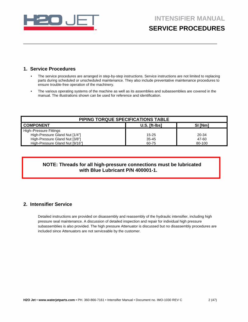
1. Service Procedures
• The service procedures are arranged in step-by-step instructions. Service instructions are not limited to replacing parts during scheduled or unscheduled maintenance. They also include preventative maintenance procedures to ensure trouble-free operation of the machinery.
• The various operating systems of the machine as well as its assemblies and subassemblies are covered in the manual. The illustrations shown can be used for reference and identification.
NOTE: Threads for all high-pressure connections must be lubricated with Blue Lubricant P/N 400001-1.
2. Intensifier Service
Detailed instructions are provided on disassembly and reassembly of the hydraulic intensifier, including high pressure seal maintenance. A discussion of detailed inspection and repair for individual high pressure subassemblies is also provided. The high pressure Attenuator is discussed but no disassembly procedures are included since Attenuators are not serviceable by the customer.
PIPING TORQUE SPECIFICATIONS TABLE COMPONENT U.S. [ft-lbs] SI [Nm] High–Pressure Fittings
High-Pressure Gland Nut [1/4”] High-Pressure Gland Nut [3/8”] High-Pressure Gland Nut [9/16”]
15-25 35-45 60-75
20-34 47-60 80-100
INTENSIFIER MANUAL
SERVICE PROCEDURES
H2O Jet • www.waterjetparts.com • PH. 360-866-7161 • Intensifier Manual • Document no. IMO-1030 REV C 3 (47)
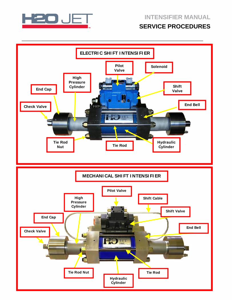
End Cap
High Pressure Cylinder
End Bell
Solenoid
Shift Valve
Check Valve
Pilot Valve
Tie Rod Nut
Hydraulic Cylinder Tie Rod
ELECTRIC SHIFT INTENSIFIER
MECHANICAL SHIFT INTENSIFIER
Check Valve
End Cap
HighPressureCylinder
End Bell
Pilot Valve
Shift Cable
Shift Valve
HydraulicCylinder
Tie Rod Nut Tie Rod
INTENSIFIER MANUAL
SERVICE PROCEDURES
H2O Jet • www.waterjetparts.com • PH. 360-866-7161 • Intensifier Manual • Document no. IMO-1030 REV C 4 (47)
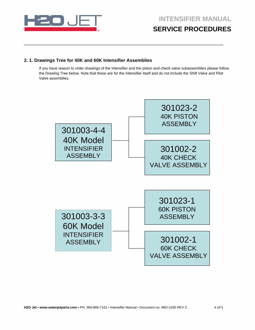
2. 1. Drawings Tree for 40K and 60K Intensifier Assemblies
If you have reason to order drawings of the Intensifier and the piston and check valve subassemblies please follow the Drawing Tree below. Note that these are for the Intensifier itself and do not include the Shift Valve and Pilot Valve assemblies.
301023-2 40K PISTON ASSEMBLY
301002-2 40K CHECK
VALVE ASSEMBLY
301003-3-3 60K Model INTENSIFIER ASSEMBLY
301023-1 60K PISTON ASSEMBLY
301002-1 60K CHECK
VALVE ASSEMBLY
301003-4-4 40K Model INTENSIFIER ASSEMBLY
INTENSIFIER MANUAL
SERVICE PROCEDURES
H2O Jet • www.waterjetparts.com • PH. 360-866-7161 • Intensifier Manual • Document no. IMO-1030 REV C 5 (47)
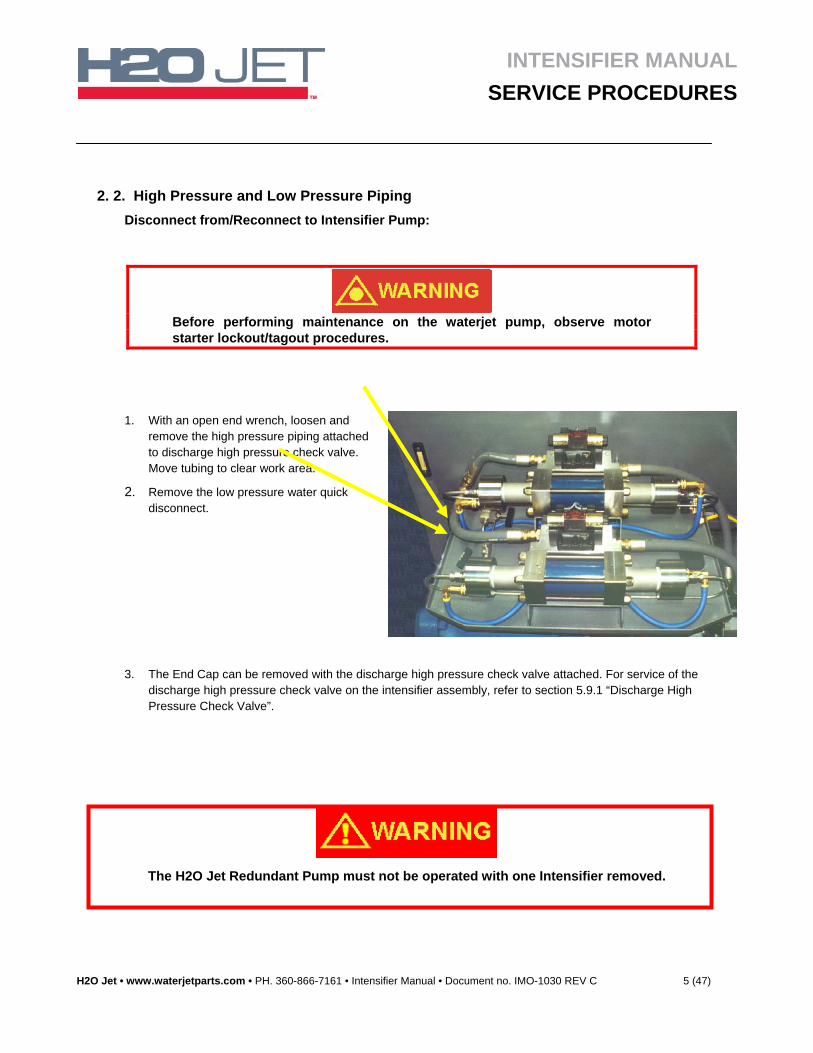
2. 2. High Pressure and Low Pressure Piping
Disconnect from/Reconnect to Intensifier Pump:
Before performing maintenance on the waterjet pump, observe motor starter lockout/tagout procedures.
3. The End Cap can be removed with the discharge high pressure check valve attached. For service of the discharge high pressure check valve on the intensifier assembly, refer to section 5.9.1 “Discharge High Pressure Check Valve”.
1. With an open end wrench, loosen and remove the high pressure piping attached to discharge high pressure check valve. Move tubing to clear work area.
2. Remove the low pressure water quick disconnect.
The H2O Jet Redundant Pump must not be operated with one Intensifier removed.
INTENSIFIER MANUAL
SERVICE PROCEDURES
H2O Jet • www.waterjetparts.com • PH. 360-866-7161 • Intensifier Manual • Document no. IMO-1030 REV C 6 (47)
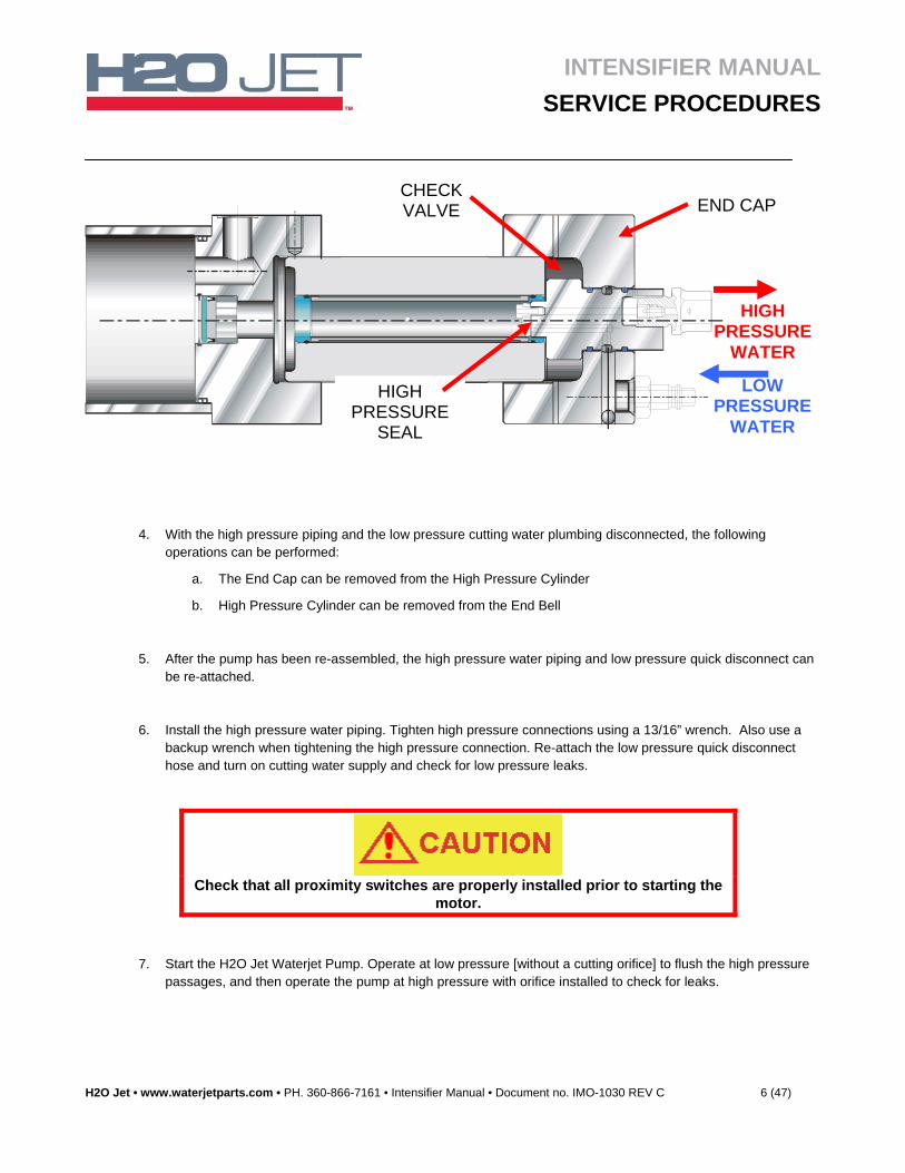
4. With the high pressure piping and the low pressure cutting water plumbing disconnected, the following operations can be performed:
a. The End Cap can be removed from the High Pressure Cylinder
b. High Pressure Cylinder can be removed from the End Bell
5. After the pump has been re-assembled, the high pressure water piping and low pressure quick disconnect can be re-attached.
6. Install the high pressure water piping. Tighten high pressure connections using a 13/16” wrench. Also use a backup wrench when tightening the high pressure connection. Re-attach the low pressure quick disconnect hose and turn on cutting water supply and check for low pressure leaks.
Check that all proximity switches are properly installed prior to starting the
motor.
7. Start the H2O Jet Waterjet Pump. Operate at low pressure [without a cutting orifice] to flush the high pressure passages, and then operate the pump at high pressure with orifice installed to check for leaks.
END CAPCHECK VALVE
HIGH PRESSURE
WATER
LOW PRESSURE
WATER
HIGH PRESSURE
SEAL
INTENSIFIER MANUAL
SERVICE PROCEDURES
H2O Jet • www.waterjetparts.com • PH. 360-866-7161 • Intensifier Manual • Document no. IMO-1030 REV C 7 (47)
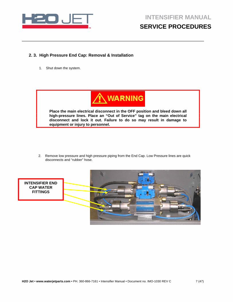
2. 3. High Pressure End Cap: Removal & Installation
1. Shut down the system.
Place the main electrical disconnect in the OFF position and bleed down all high-pressure lines. Place an “Out of Service” tag on the main electrical disconnect and lock it out. Failure to do so may result in damage to equipment or injury to personnel.
2. Remove low pressure and high pressure piping from the End Cap. Low Pressure lines are quick disconnects and “rubber” hose.
INTENSIFIER END CAP WATER
FITTINGS
INTENSIFIER MANUAL
SERVICE PROCEDURES
H2O Jet • www.waterjetparts.com • PH. 360-866-7161 • Intensifier Manual • Document no. IMO-1030 REV C 8 (47)
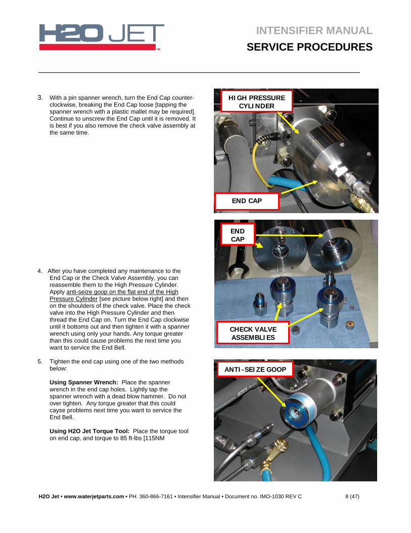
4. After you have completed any maintenance to the End Cap or the Check Valve Assembly, you can reassemble them to the High Pressure Cylinder. Apply anti-seize goop on the flat end of the High Pressure Cylinder [see picture below right] and then on the shoulders of the check valve. Place the check valve into the High Pressure Cylinder and then thread the End Cap on. Turn the End Cap clockwise until it bottoms out and then tighten it with a spanner wrench using only your hands. Any torque greater than this could cause problems the next time you want to service the End Bell.
5. Tighten the end cap using one of the two methods
below:
Using Spanner Wrench: Place the spanner wrench in the end cap holes. Lightly tap the spanner wrench with a dead blow hammer. Do not over tighten. Any torque greater that this could cayse problems next time you want to service the End Bell. Using H2O Jet Torque Tool: Place the torque tool on end cap, and torque to 85 ft-lbs [115NM
3. With a pin spanner wrench, turn the End Cap counter-clockwise, breaking the End Cap loose [tapping the spanner wrench with a plastic mallet may be required]. Continue to unscrew the End Cap until it is removed. It is best if you also remove the check valve assembly at the same time.
HIGH PRESSURE CYLINDER
END CAP
END CAP
CHECK VALVE ASSEMBLIES
ANTI-SEIZE GOOP
INTENSIFIER MANUAL
SERVICE PROCEDURES
H2O Jet • www.waterjetparts.com • PH. 360-866-7161 • Intensifier Manual • Document no. IMO-1030 REV C 9 (47)
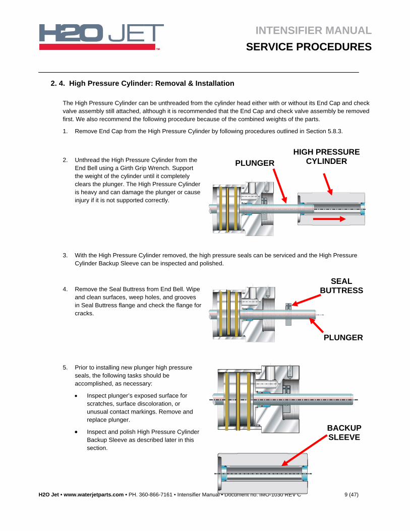
2. 4. High Pressure Cylinder: Removal & Installation
The High Pressure Cylinder can be unthreaded from the cylinder head either with or without its End Cap and check valve assembly still attached, although it is recommended that the End Cap and check valve assembly be removed first. We also recommend the following procedure because of the combined weights of the parts.
1. Remove End Cap from the High Pressure Cylinder by following procedures outlined in Section 5.8.3.
3. With the High Pressure Cylinder removed, the high pressure seals can be serviced and the High Pressure Cylinder Backup Sleeve can be inspected and polished.
2. Unthread the High Pressure Cylinder from the End Bell using a Girth Grip Wrench. Support the weight of the cylinder until it completely clears the plunger. The High Pressure Cylinder is heavy and can damage the plunger or cause injury if it is not supported correctly.
4. Remove the Seal Buttress from End Bell. Wipe and clean surfaces, weep holes, and grooves in Seal Buttress flange and check the flange for cracks.
5. Prior to installing new plunger high pressure seals, the following tasks should be accomplished, as necessary:
Inspect plunger’s exposed surface for scratches, surface discoloration, or unusual contact markings. Remove and replace plunger.
Inspect and polish High Pressure Cylinder Backup Sleeve as described later in this section.
SEAL BUTTRESS
PLUNGER
HIGH PRESSURE CYLINDER PLUNGER
BACKUP SLEEVE
INTENSIFIER MANUAL
SERVICE PROCEDURES
H2O Jet • www.waterjetparts.com • PH. 360-866-7161 • Intensifier Manual • Document no. IMO-1030 REV C 10 (47)
6. Inspect the High Pressure Cylinder threads and apply Anti-Seize Goop to the threads and shoulder guides. Be careful not to slam the High Pressure Cylinder up against the End Bell because this could damage the threads. Screw the High Pressure Cylinder into the hydraulic cylinder head. Note that shoulder guides are close fitting smooth diameters located at either end of cylinder threads. Be sure to support the weight of the High Pressure Cylinder. As the high pressure plunger goes into the cylinder, the cylinder will become difficult to rotate. Use the special cylinder wrench to assist, as necessary.
7. Tighten the High Pressure Cylinder hand tight. Do not tighten any tighter than hand tight.
8. Follow the procedure in section 2.3 for installation of the End Caps.
INTENSIFIER MANUAL
SERVICE PROCEDURES
H2O Jet • www.waterjetparts.com • PH. 360-866-7161 • Intensifier Manual • Document no. IMO-1030 REV C 11 (47)
2. 5. High Pressure Cylinder Seals: Removal & Installation
1. Remove the high pressure and low pressure water lines using the procedure described in Section 2.2.
2. Remove the End Cap using the procedure described in Section 2.3.
3. Remove the High Pressure Cylinder using the procedure described in Section 2.4.
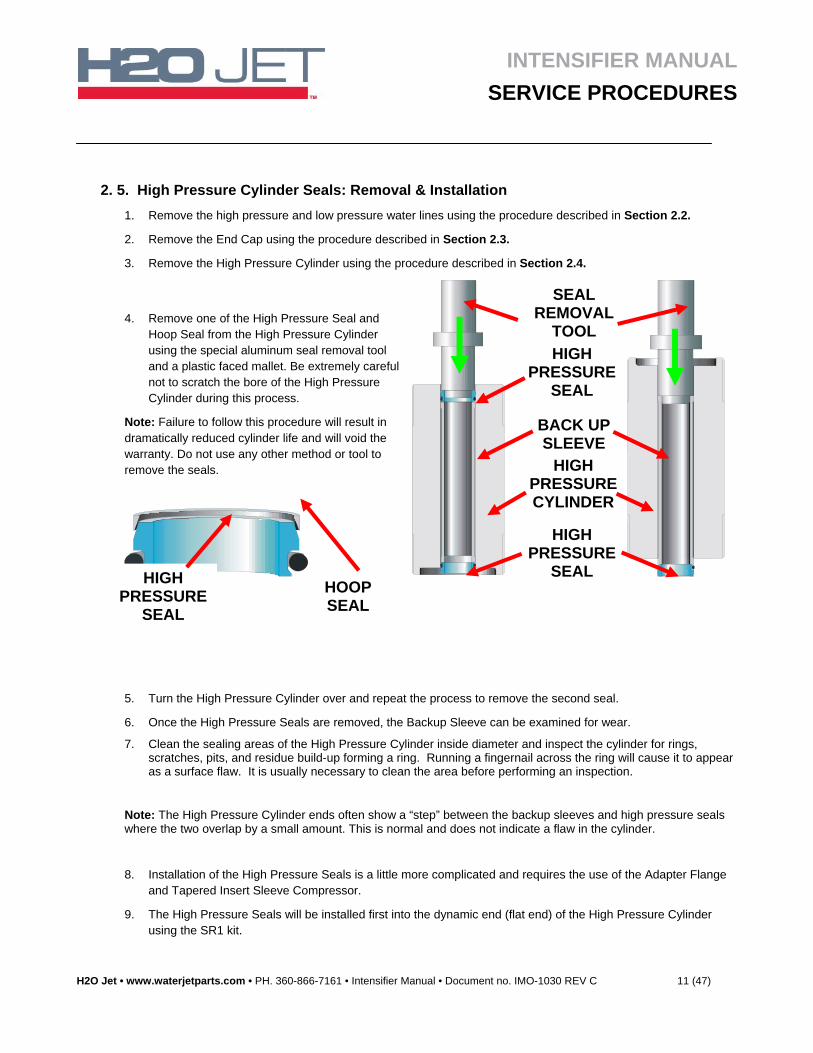
5. Turn the High Pressure Cylinder over and repeat the process to remove the second seal.
6. Once the High Pressure Seals are removed, the Backup Sleeve can be examined for wear.
7. Clean the sealing areas of the High Pressure Cylinder inside diameter and inspect the cylinder for rings, scratches, pits, and residue build-up forming a ring. Running a fingernail across the ring will cause it to appear as a surface flaw. It is usually necessary to clean the area before performing an inspection.
Note: The High Pressure Cylinder ends often show a “step” between the backup sleeves and high pressure seals where the two overlap by a small amount. This is normal and does not indicate a flaw in the cylinder.
8. Installation of the High Pressure Seals is a little more complicated and requires the use of the Adapter Flange and Tapered Insert Sleeve Compressor.
9. The High Pressure Seals will be installed first into the dynamic end (flat end) of the High Pressure Cylinder using the SR1 kit.
4. Remove one of the High Pressure Seal and Hoop Seal from the High Pressure Cylinder using the special aluminum seal removal tool and a plastic faced mallet. Be extremely careful not to scratch the bore of the High Pressure Cylinder during this process.
Note: Failure to follow this procedure will result in dramatically reduced cylinder life and will void the warranty. Do not use any other method or tool to remove the seals.
SEAL REMOVAL
TOOL
BACK UP SLEEVE
HIGH PRESSURE CYLINDER
HIGH PRESSURE
SEAL
HIGH PRESSURE
SEAL
HIGH PRESSURE
SEAL
HOOP SEAL
INTENSIFIER MANUAL
SERVICE PROCEDURES
H2O Jet • www.waterjetparts.com • PH. 360-866-7161 • Intensifier Manual • Document no. IMO-1030 REV C 12 (47)
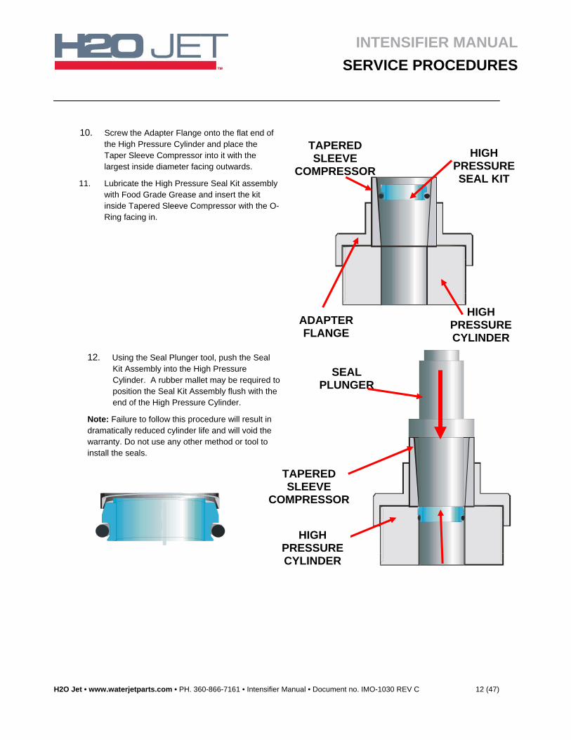
10. Screw the Adapter Flange onto the flat end of the High Pressure Cylinder and place the Taper Sleeve Compressor into it with the largest inside diameter facing outwards.
11. Lubricate the High Pressure Seal Kit assembly with Food Grade Grease and insert the kit inside Tapered Sleeve Compressor with the O-Ring facing in.
12. Using the Seal Plunger tool, push the Seal Kit Assembly into the High Pressure Cylinder. A rubber mallet may be required to position the Seal Kit Assembly flush with the end of the High Pressure Cylinder.
Note: Failure to follow this procedure will result in dramatically reduced cylinder life and will void the warranty. Do not use any other method or tool to install the seals.
HIGH PRESSURE SEAL KIT
ADAPTER FLANGE
HIGH PRESSURE CYLINDER
TAPERED SLEEVE
COMPRESSOR
TAPERED SLEEVE
COMPRESSOR
HIGH PRESSURE CYLINDER
SEAL PLUNGER
INTENSIFIER MANUAL
SERVICE PROCEDURES
H2O Jet • www.waterjetparts.com • PH. 360-866-7161 • Intensifier Manual • Document no. IMO-1030 REV C 13 (47)
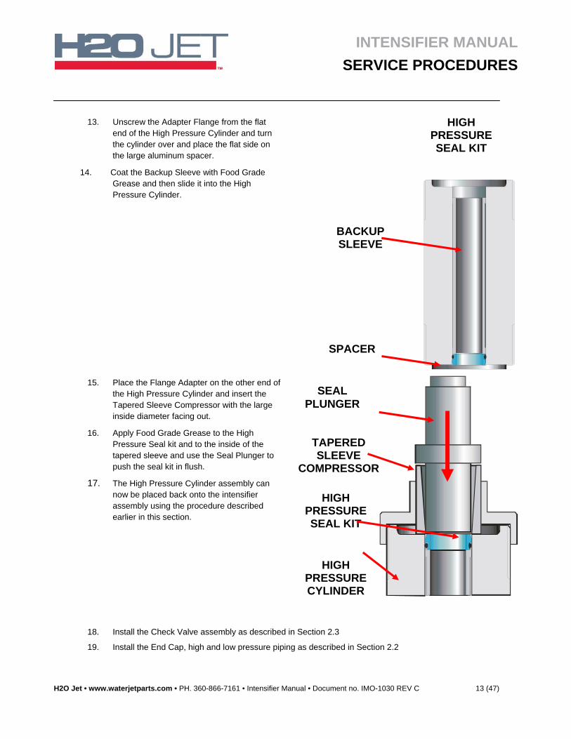
13. Unscrew the Adapter Flange from the flat end of the High Pressure Cylinder and turn the cylinder over and place the flat side on the large aluminum spacer.
14. Coat the Backup Sleeve with Food Grade Grease and then slide it into the High Pressure Cylinder.
15. Place the Flange Adapter on the other end of the High Pressure Cylinder and insert the Tapered Sleeve Compressor with the large inside diameter facing out.
16. Apply Food Grade Grease to the High Pressure Seal kit and to the inside of the tapered sleeve and use the Seal Plunger to push the seal kit in flush.
17. The High Pressure Cylinder assembly can now be placed back onto the intensifier assembly using the procedure described earlier in this section.
18. Install the Check Valve assembly as described in Section 2.3
19. Install the End Cap, high and low pressure piping as described in Section 2.2
BACKUP SLEEVE
SPACER
HIGH PRESSURE SEAL KIT
TAPERED SLEEVE
COMPRESSOR
HIGH PRESSURE CYLINDER
SEAL PLUNGER
HIGH PRESSURE SEAL KIT
INTENSIFIER MANUAL
SERVICE PROCEDURES
H2O Jet • www.waterjetparts.com • PH. 360-866-7161 • Intensifier Manual • Document no. IMO-1030 REV C 14 (47)
2. 6. End Bell
With the High Pressure Cylinder removed, the Hydraulic End Bell can be easily removed and the Hydraulic Cylinder components can be serviced.
Plunger
Hydraulic Cylinder End Bell
Hydraulic Piston and Cylinder
The plunger surfaces can become streaked with longitudinal scratches or flaws, the surface can become discolored or dull in appearance, or the outboard end can become smeared with stainless steel due to contact with the bore liner. If any of these conditions become severe, the plunger high pressure seal and possibly, the hydraulic seals will leak excessively. Repair of the plunger surface flaws usually cannot be accomplished on site. H2O Jet offers a plunger reconditioning service.
Note that the directional shifting valve assembly comes as either top mount or side mount. Aside from the placement, all other aspects regarding servicing are the same for either configuration.
1. Remove the End Cap and the High Pressure Cylinder using the procedures in Sections 2.2. through 2.4.
2. Remove the proximity switch or Switch Cable Assembly at the cylinder end to be serviced. Remove the remaining proximity switch to drain the hydraulic oil into the tank if you are going to service both ends of the hydraulic cylinder.
3. Loosen and remove the tie rods and nuts (4) retaining the End Bell to the hydraulic cylinder. The End Bell and Seals can now be replaced.
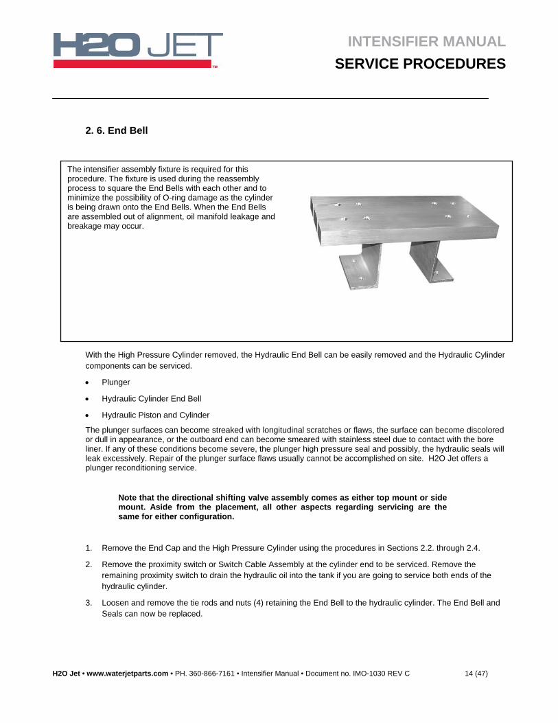
The intensifier assembly fixture is required for this procedure. The fixture is used during the reassembly process to square the End Bells with each other and to minimize the possibility of O-ring damage as the cylinder is being drawn onto the End Bells. When the End Bells are assembled out of alignment, oil manifold leakage and breakage may occur.
INTENSIFIER MANUAL
SERVICE PROCEDURES
H2O Jet • www.waterjetparts.com • PH. 360-866-7161 • Intensifier Manual • Document no. IMO-1030 REV C 15 (47)
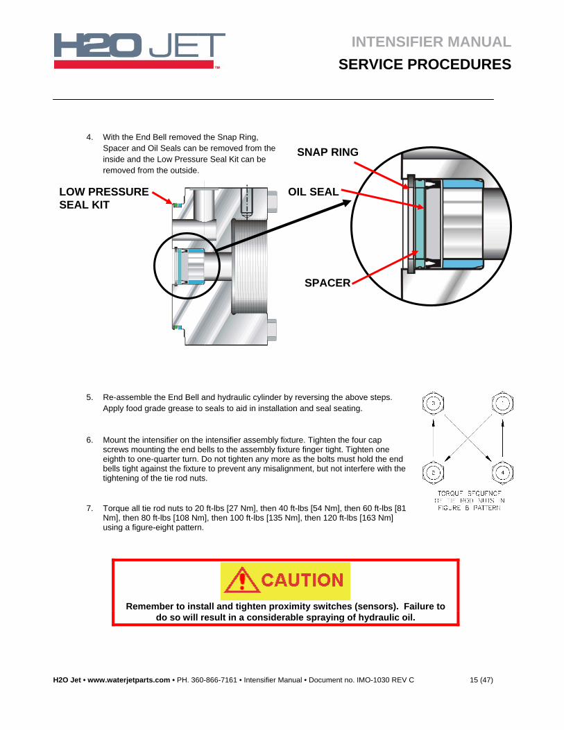
4. With the End Bell removed the Snap Ring, Spacer and Oil Seals can be removed from the inside and the Low Pressure Seal Kit can be removed from the outside.
5. Re-assemble the End Bell and hydraulic cylinder by reversing the above steps. Apply food grade grease to seals to aid in installation and seal seating.
6. Mount the intensifier on the intensifier assembly fixture. Tighten the four cap screws mounting the end bells to the assembly fixture finger tight. Tighten one eighth to one-quarter turn. Do not tighten any more as the bolts must hold the end bells tight against the fixture to prevent any misalignment, but not interfere with the tightening of the tie rod nuts.
7. Torque all tie rod nuts to 20 ft-lbs [27 Nm], then 40 ft-lbs [54 Nm], then 60 ft-lbs [81 Nm], then 80 ft-lbs [108 Nm], then 100 ft-lbs [135 Nm], then 120 ft-lbs [163 Nm] using a figure-eight pattern.
Remember to install and tighten proximity switches (sensors). Failure to
do so will result in a considerable spraying of hydraulic oil.
SNAP RING
OIL SEAL
SPACER
LOW PRESSURE SEAL KIT
INTENSIFIER MANUAL
SERVICE PROCEDURES
H2O Jet • www.waterjetparts.com • PH. 360-866-7161 • Intensifier Manual • Document no. IMO-1030 REV C 16 (47)
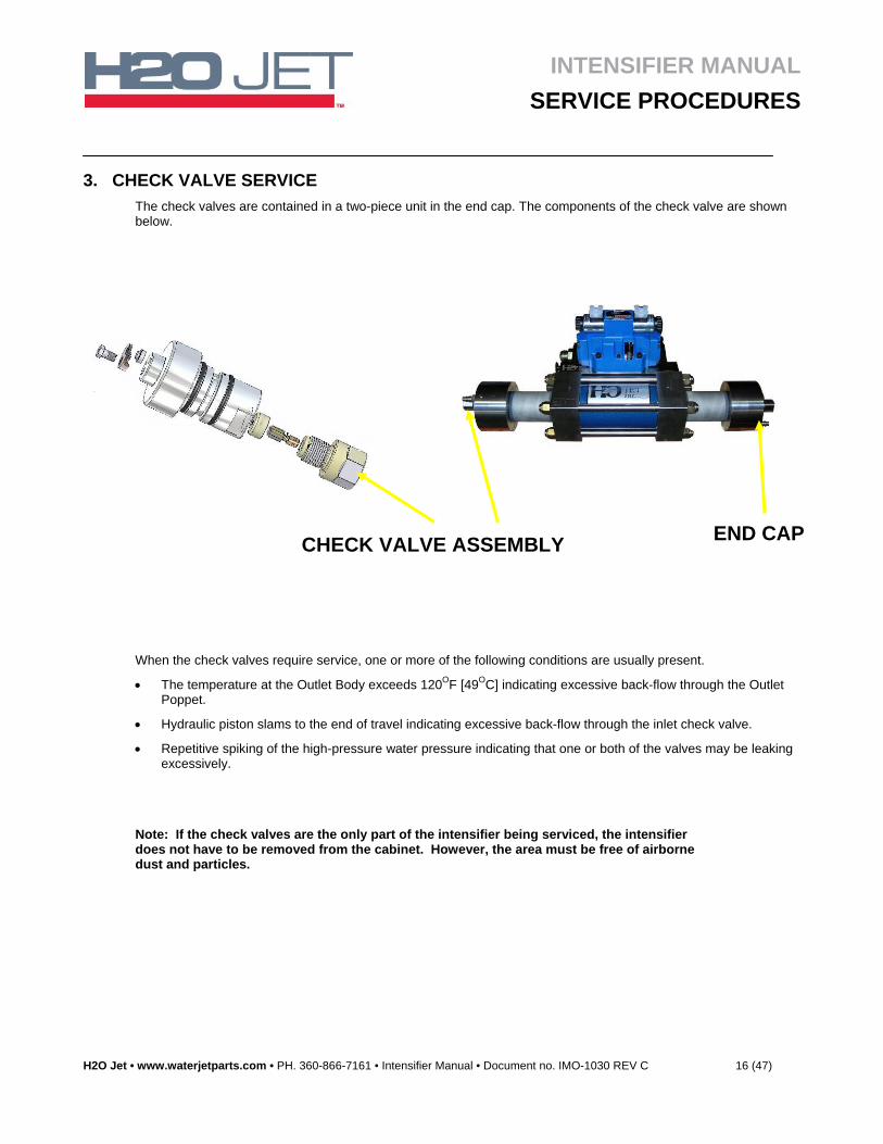
3. CHECK VALVE SERVICE
The check valves are contained in a two-piece unit in the end cap. The components of the check valve are shown below.
When the check valves require service, one or more of the following conditions are usually present.
The temperature at the Outlet Body exceeds 120OF [49OC] indicating excessive back-flow through the Outlet Poppet.
Hydraulic piston slams to the end of travel indicating excessive back-flow through the inlet check valve.
Repetitive spiking of the high-pressure water pressure indicating that one or both of the valves may be leaking excessively.
Note: If the check valves are the only part of the intensifier being serviced, the intensifier does not have to be removed from the cabinet. However, the area must be free of airborne dust and particles.
END CAP CHECK VALVE ASSEMBLY
INTENSIFIER MANUAL
SERVICE PROCEDURES
H2O Jet • www.waterjetparts.com • PH. 360-866-7161 • Intensifier Manual • Document no. IMO-1030 REV C 17 (47)
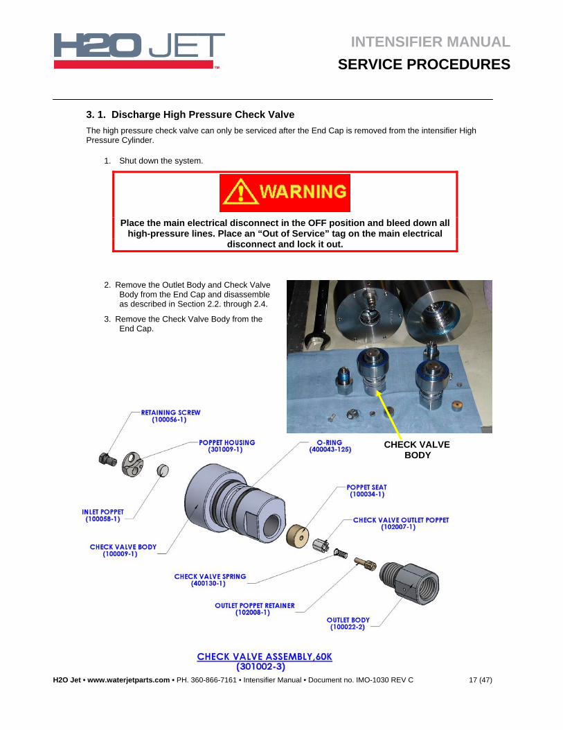
3. 1. Discharge High Pressure Check Valve
The high pressure check valve can only be serviced after the End Cap is removed from the intensifier High Pressure Cylinder.
1. Shut down the system.
Place the main electrical disconnect in the OFF position and bleed down all
high-pressure lines. Place an “Out of Service” tag on the main electrical disconnect and lock it out.
2. Remove the Outlet Body and Check Valve Body from the End Cap and disassemble as described in Section 2.2. through 2.4.
3. Remove the Check Valve Body from the End Cap.
CHECK VALVE BODY
INTENSIFIER MANUAL
SERVICE PROCEDURES
H2O Jet • www.waterjetparts.com • PH. 360-866-7161 • Intensifier Manual • Document no. IMO-1030 REV C 18 (47)
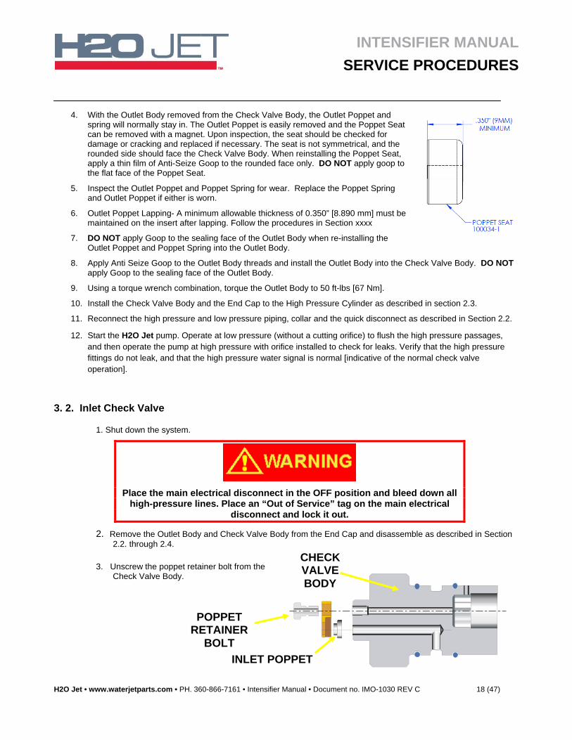
4. With the Outlet Body removed from the Check Valve Body, the Outlet Poppet and spring will normally stay in. The Outlet Poppet is easily removed and the Poppet Seat can be removed with a magnet. Upon inspection, the seat should be checked for damage or cracking and replaced if necessary. The seat is not symmetrical, and the rounded side should face the Check Valve Body. When reinstalling the Poppet Seat, apply a thin film of Anti-Seize Goop to the rounded face only. DO NOT apply goop to the flat face of the Poppet Seat.
5. Inspect the Outlet Poppet and Poppet Spring for wear. Replace the Poppet Spring and Outlet Poppet if either is worn.
6. Outlet Poppet Lapping- A minimum allowable thickness of 0.350” [8.890 mm] must be maintained on the insert after lapping. Follow the procedures in Section xxxx
7. DO NOT apply Goop to the sealing face of the Outlet Body when re-installing the Outlet Poppet and Poppet Spring into the Outlet Body.
8. Apply Anti Seize Goop to the Outlet Body threads and install the Outlet Body into the Check Valve Body. DO NOT apply Goop to the sealing face of the Outlet Body.
9. Using a torque wrench combination, torque the Outlet Body to 50 ft-lbs [67 Nm].
10. Install the Check Valve Body and the End Cap to the High Pressure Cylinder as described in section 2.3.
11. Reconnect the high pressure and low pressure piping, collar and the quick disconnect as described in Section 2.2.
12. Start the H2O Jet pump. Operate at low pressure (without a cutting orifice) to flush the high pressure passages, and then operate the pump at high pressure with orifice installed to check for leaks. Verify that the high pressure fittings do not leak, and that the high pressure water signal is normal [indicative of the normal check valve operation].
3. 2. Inlet Check Valve
1. Shut down the system.
Place the main electrical disconnect in the OFF position and bleed down all
high-pressure lines. Place an “Out of Service” tag on the main electrical disconnect and lock it out.
2. Remove the Outlet Body and Check Valve Body from the End Cap and disassemble as described in Section 2.2. through 2.4.
3. Unscrew the poppet retainer bolt from the Check Valve Body.
POPPET RETAINER
BOLT
CHECK VALVE BODY
INLET POPPET
INTENSIFIER MANUAL
SERVICE PROCEDURES
H2O Jet • www.waterjetparts.com • PH. 360-866-7161 • Intensifier Manual • Document no. IMO-1030 REV C 19 (47)
Figure 1
FIGURE 2
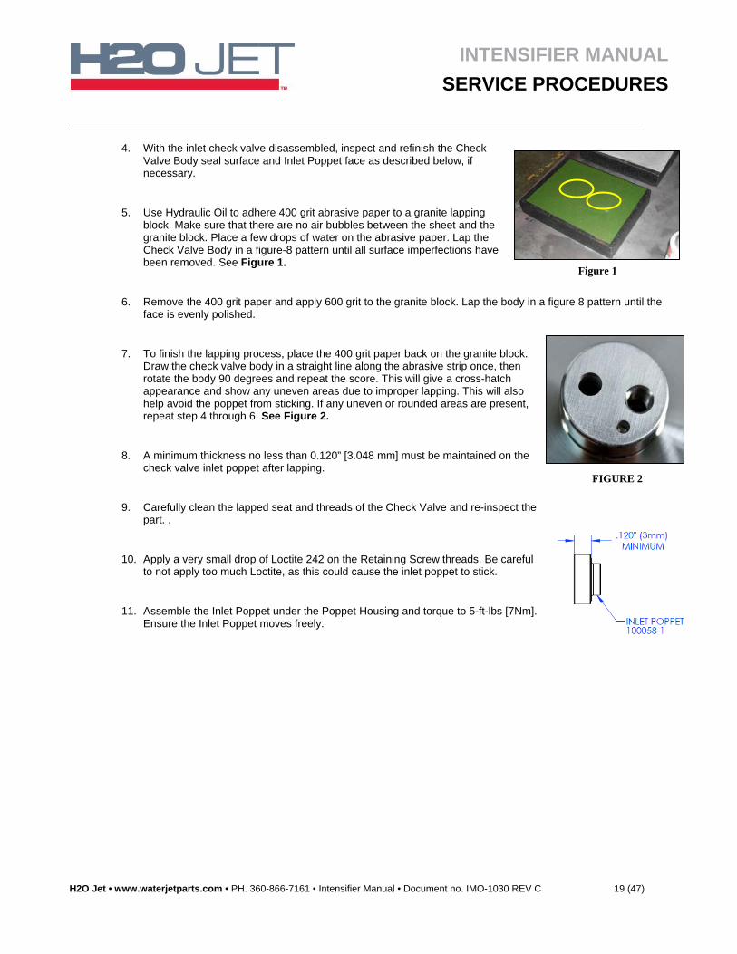
4. With the inlet check valve disassembled, inspect and refinish the Check Valve Body seal surface and Inlet Poppet face as described below, if necessary.
5. Use Hydraulic Oil to adhere 400 grit abrasive paper to a granite lapping block. Make sure that there are no air bubbles between the sheet and the granite block. Place a few drops of water on the abrasive paper. Lap the Check Valve Body in a figure-8 pattern until all surface imperfections have been removed. See Figure 1.
6. Remove the 400 grit paper and apply 600 grit to the granite block. Lap the body in a figure 8 pattern until the face is evenly polished.
7. To finish the lapping process, place the 400 grit paper back on the granite block. Draw the check valve body in a straight line along the abrasive strip once, then rotate the body 90 degrees and repeat the score. This will give a cross-hatch appearance and show any uneven areas due to improper lapping. This will also help avoid the poppet from sticking. If any uneven or rounded areas are present, repeat step 4 through 6. See Figure 2.
8. A minimum thickness no less than 0.120” [3.048 mm] must be maintained on the check valve inlet poppet after lapping.
9. Carefully clean the lapped seat and threads of the Check Valve and re-inspect the part. .
10. Apply a very small drop of Loctite 242 on the Retaining Screw threads. Be careful to not apply too much Loctite, as this could cause the inlet poppet to stick.
11. Assemble the Inlet Poppet under the Poppet Housing and torque to 5-ft-lbs [7Nm]. Ensure the Inlet Poppet moves freely.
INTENSIFIER MANUAL
SERVICE PROCEDURES
H2O Jet • www.waterjetparts.com • PH. 360-866-7161 • Intensifier Manual • Document no. IMO-1030 REV C 20 (47)
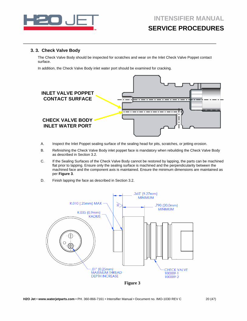
3. 3. Check Valve Body
The Check Valve Body should be inspected for scratches and wear on the Inlet Check Valve Poppet contact surface.
In addition, the Check Valve Body inlet water port should be examined for cracking.
A. Inspect the Inlet Poppet sealing surface of the sealing head for pits, scratches, or jetting erosion.
B. Refinishing the Check Valve Body inlet poppet face is mandatory when rebuilding the Check Valve Body as described in Section 3.2.
C. If the Sealing Surfaces of the Check Valve Body cannot be restored by lapping, the parts can be machined flat prior to lapping. Ensure only the sealing surface is machined and the perpendicularity between the machined face and the component axis is maintained. Ensure the minimum dimensions are maintained as per Figure 3.
D. Finish lapping the face as described in Section 3.2.
INLET VALVE POPPET CONTACT SURFACE
CHECK VALVE BODY INLET WATER PORT
Figure 3
INTENSIFIER MANUAL
SERVICE PROCEDURES
H2O Jet • www.waterjetparts.com • PH. 360-866-7161 • Intensifier Manual • Document no. IMO-1030 REV C 21 (47)
4. Piston Service
The inside diameter surface of the hydraulic cylinder should be inspected for any wear grooves and the surface finished whenever the hydraulic End Bells are removed. Excessive grooving on the hydraulic cylinder bore is indicative of piston seal wear.
When the piston assembly requires service, one of the following conditions is usually present.
• Worn piston seals allowing excessive oil flow around the piston.
• A jammed piston or detached plunger.
Disassembly of the Hydraulic Oil Cylinder, End Bells, and High Pressure Cylinders to access the piston involves the removal of the intensifier from the cabinet and a complete teardown of the intensifier on a workbench. An experienced technician using the proper tools and procedures can usually complete the procedure in 2 to 3 hours.
1. Shut down the system
Before performing maintenance on the waterjet pump observe motor
starter lock out/tag out procedures.
2. Remove the High Pressure and Low Pressure piping as described in Section 2.2.
3. Remove the intensifier from the cabinet.
4. Remove the End Cap and the High Pressure Cylinder using the procedures in Sections 2.3. and 2.4.
5. Remove the proximity switches at the cylinder ends to drain the hydraulic oil out of the cylinder.
INTENSIFIER MANUAL
SERVICE PROCEDURES
H2O Jet • www.waterjetparts.com • PH. 360-866-7161 • Intensifier Manual • Document no. IMO-1030 REV C 22 (47)
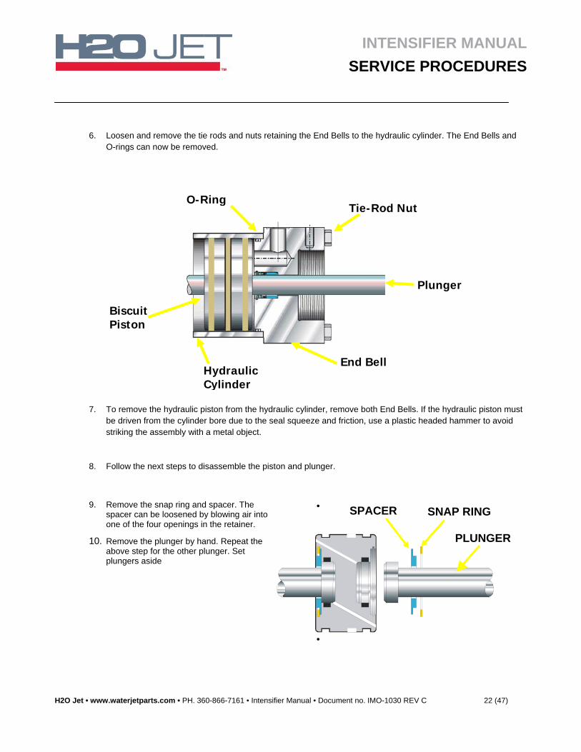
6. Loosen and remove the tie rods and nuts retaining the End Bells to the hydraulic cylinder. The End Bells and O-rings can now be removed.
7. To remove the hydraulic piston from the hydraulic cylinder, remove both End Bells. If the hydraulic piston must be driven from the cylinder bore due to the seal squeeze and friction, use a plastic headed hammer to avoid striking the assembly with a metal object.
8. Follow the next steps to disassemble the piston and plunger.
9. Remove the snap ring and spacer. The spacer can be loosened by blowing air into one of the four openings in the retainer.
10. Remove the plunger by hand. Repeat the above step for the other plunger. Set plungers aside
•
•
SNAP RING SPACER
PLUNGER
O-Ring Tie-Rod Nut
End BellHydraulic Cylinder
Biscuit Piston
Plunger
INTENSIFIER MANUAL
SERVICE PROCEDURES
H2O Jet • www.waterjetparts.com • PH. 360-866-7161 • Intensifier Manual • Document no. IMO-1030 REV C 23 (47)
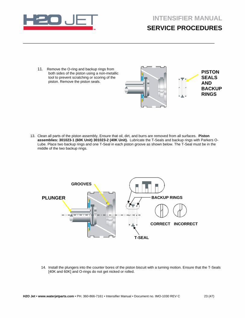
11. Remove the O-ring and backup rings from both sides of the piston using a non-metallic tool to prevent scratching or scoring of the piston. Remove the piston seals.
13. Clean all parts of the piston assembly, Ensure that oil, dirt, and burrs are removed from all surfaces. Piston assemblies: 301023-1 (60K Unit) 301023-2 (40K Unit). Lubricate the T-Seals and backup rings with Parkers O-Lube. Place two backup rings and one T-Seal in each piston groove as shown below. The T-Seal must be in the middle of the two backup rings.
14. Install the plungers into the counter bores of the piston biscuit with a turning motion. Ensure that the T-Seals [40K and 60K] and O-rings do not get nicked or rolled.
CORRECT INCORRECT
BACKUP RINGS
T-SEAL
GROOVES
PISTON SEALS AND BACKUP RINGS
PLUNGER
INTENSIFIER MANUAL
SERVICE PROCEDURES
H2O Jet • www.waterjetparts.com • PH. 360-866-7161 • Intensifier Manual • Document no. IMO-1030 REV C 24 (47)
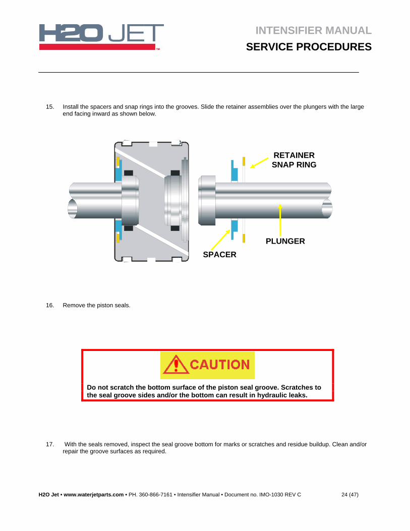
15. Install the spacers and snap rings into the grooves. Slide the retainer assemblies over the plungers with the large end facing inward as shown below.
16. Remove the piston seals.
Do not scratch the bottom surface of the piston seal groove. Scratches to the seal groove sides and/or the bottom can result in hydraulic leaks.
17. With the seals removed, inspect the seal groove bottom for marks or scratches and residue buildup. Clean and/or repair the groove surfaces as required.
RETAINER SNAP RING
SPACER
PLUNGER
INTENSIFIER MANUAL
SERVICE PROCEDURES
H2O Jet • www.waterjetparts.com • PH. 360-866-7161 • Intensifier Manual • Document no. IMO-1030 REV C 25 (47)
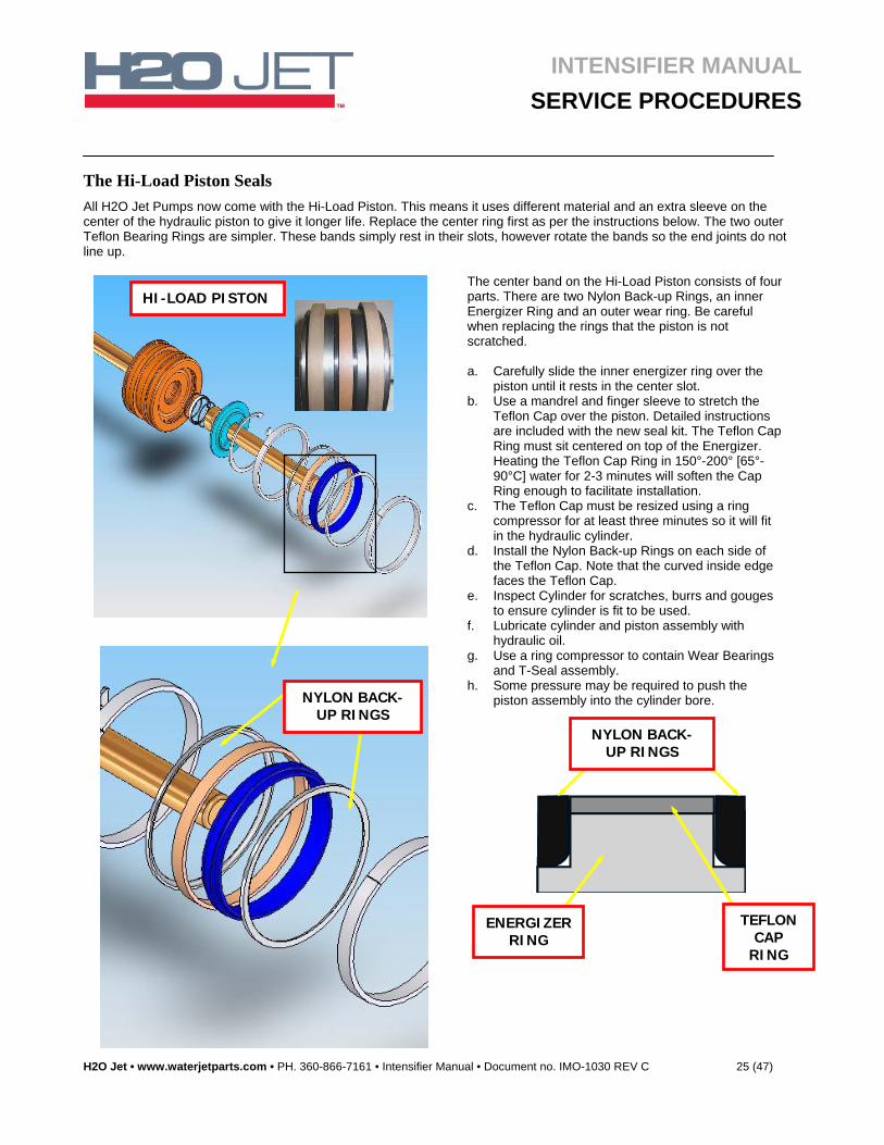
The Hi-Load Piston Seals
All H2O Jet Pumps now come with the Hi-Load Piston. This means it uses different material and an extra sleeve on the center of the hydraulic piston to give it longer life. Replace the center ring first as per the instructions below. The two outer Teflon Bearing Rings are simpler. These bands simply rest in their slots, however rotate the bands so the end joints do not line up.
The center band on the Hi-Load Piston consists of four parts. There are two Nylon Back-up Rings, an inner Energizer Ring and an outer wear ring. Be careful when replacing the rings that the piston is not scratched.
a. Carefully slide the inner energizer ring over the
piston until it rests in the center slot. b. Use a mandrel and finger sleeve to stretch the
Teflon Cap over the piston. Detailed instructions are included with the new seal kit. The Teflon Cap Ring must sit centered on top of the Energizer. Heating the Teflon Cap Ring in 150°-200° [65°-90°C] water for 2-3 minutes will soften the Cap Ring enough to facilitate installation.
c. The Teflon Cap must be resized using a ring compressor for at least three minutes so it will fit in the hydraulic cylinder.
d. Install the Nylon Back-up Rings on each side of the Teflon Cap. Note that the curved inside edge faces the Teflon Cap.
e. Inspect Cylinder for scratches, burrs and gouges to ensure cylinder is fit to be used.
f. Lubricate cylinder and piston assembly with hydraulic oil.
g. Use a ring compressor to contain Wear Bearings and T-Seal assembly.
h. Some pressure may be required to push the piston assembly into the cylinder bore.
HI-LOAD PISTON
NYLON BACK-UP RINGS
TEFLON CAP
RING
ENERGIZER RING
NYLON BACK-UP RINGS
INTENSIFIER MANUAL
SERVICE PROCEDURES
H2O Jet • www.waterjetparts.com • PH. 360-866-7161 • Intensifier Manual • Document no. IMO-1030 REV C 26 (47)
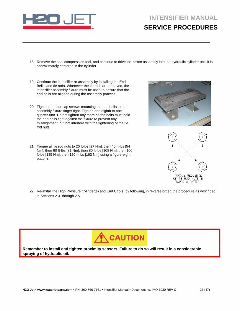
18. Remove the seal compression tool, and continue to drive the piston assembly into the hydraulic cylinder until it is approximately centered in the cylinder.
19. Continue the intensifier re-assembly by installing the End Bells, and tie rods. Whenever the tie rods are removed, the intensifier assembly fixture must be used to ensure that the end bells are aligned during the assembly process.
20. Tighten the four cap screws mounting the end bells to the assembly fixture finger tight. Tighten one eighth to one-quarter turn. Do not tighten any more as the bolts must hold the end bells tight against the fixture to prevent any misalignment, but not interfere with the tightening of the tie rod nuts.
21. Torque all tie rod nuts to 20 ft-lbs [27 Nm], then 40 ft-lbs [54 Nm], then 60 ft-lbs [81 Nm], then 80 ft-lbs [108 Nm], then 100 ft-lbs [135 Nm], then 120 ft-lbs [163 Nm] using a figure-eight pattern.
22. Re-install the High Pressure Cylinder(s) and End Cap(s) by following, in reverse order, the procedure as described in Sections 2.3. through 2.5.
Remember to install and tighten proximity sensors. Failure to do so will result in a considerable spraying of hydraulic oil.
INTENSIFIER MANUAL
SERVICE PROCEDURES
H2O Jet • www.waterjetparts.com • PH. 360-866-7161 • Intensifier Manual • Document no. IMO-1030 REV C 27 (47)
5. Electric Directional Shift
5. 1. Electric Shift Operation
1. The piston within the Hydraulic Oil Cylinder nears the end of the stroke
1. The piston makes contact with a Shift Pin
2. The Shift Pin movement is transferred to the actuator Assembly with its magnetic tip.
3. The magnet activates the Proximity Switch (sensor)
4. The Proximity Switch sends the message to the PLC (Programmable Logic Controller).
5. The PLC activates the correct Solenoid on the end of the Pilot Valve Assembly [one solenoid for each direction].
6. The solenoid pushes a shaft into the Pilot Valve housing that pushes the Pilot Valve Spool to the correct side
7. The Pilot Valve directs a small flow of oil to the end of the Directional Shift Valve moving its spool.
8. The Directional Shift Valve Spool directs the main hydraulic oil flow to the compressed side of the hydraulic cylinder.
9. The large-diameter hydraulic biscuit piston pushes the small-diameter High-Pressure Plunger (they are a single assembly).
10. The High-Pressure Plunger compresses the water up to the cutting-water pressure and sends it out the Check Valve.
11. When the piston assembly reaches the end of its stroke it contacts the Shift Pin on the other Proximity Switch (sensor) Assembly and the cycle repeats.
INTENSIFIER MANUAL
SERVICE PROCEDURES
H2O Jet • www.waterjetparts.com • PH. 360-866-7161 • Intensifier Manual • Document no. IMO-1030 REV C 28 (47)
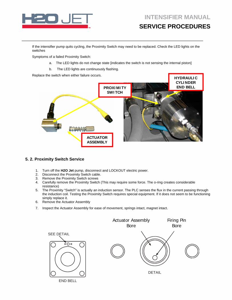
If the intensifier pump quits cycling, the Proximity Switch may need to be replaced. Check the LED lights on the switches
Symptoms of a failed Proximity Switch:
a. The LED lights do not change state [indicates the switch is not sensing the internal piston]
b. The LED lights are continuously flashing.
Replace the switch when either failure occurs.
5. 2. Proximity Switch Service
1. Turn off the H2O Jet pump, disconnect and LOCKOUT electric power. 2. Disconnect the Proximity Switch cable. 3. Remove the Proximity Switch screws 4. Carefully remove the Proximity Switch (This may require some force. The o-ring creates considerable
resistance) 5. The Proximity “Switch” is actually an induction sensor. The PLC senses the flux in the current passing through
the induction coil. Testing the Proximity Switch requires special equipment. If it does not seem to be functioning simply replace it.
6. Remove the Actuator Assembly
7. Inspect the Actuator Assembly for ease of movement, springs intact, magnet intact.
ACTUATOR ASSEMBLY
PROXIMITY SWITCH
HYDRAULIC CYLINDER END BELL
SEE DETAIL
ACTUATINGPLUNGER BORE
ACTUATINGPIN BORE
DETAIL
END BELL
Firing Pin Bore
Actuator Assembly Bore
INTENSIFIER MANUAL
SERVICE PROCEDURES
H2O Jet • www.waterjetparts.com • PH. 360-866-7161 • Intensifier Manual • Document no. IMO-1030 REV C 29 (47)
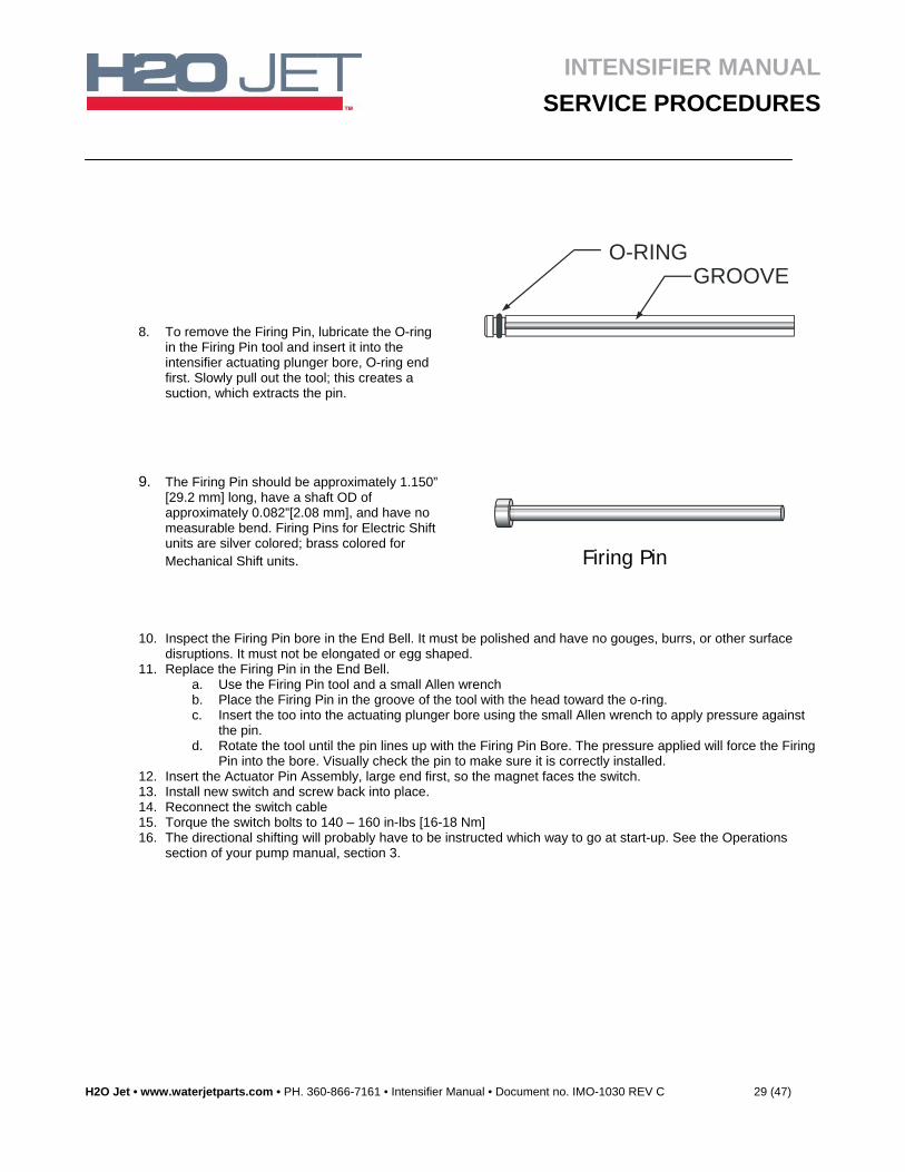
8. To remove the Firing Pin, lubricate the O-ring in the Firing Pin tool and insert it into the intensifier actuating plunger bore, O-ring end first. Slowly pull out the tool; this creates a suction, which extracts the pin.
O-RINGGROOVE
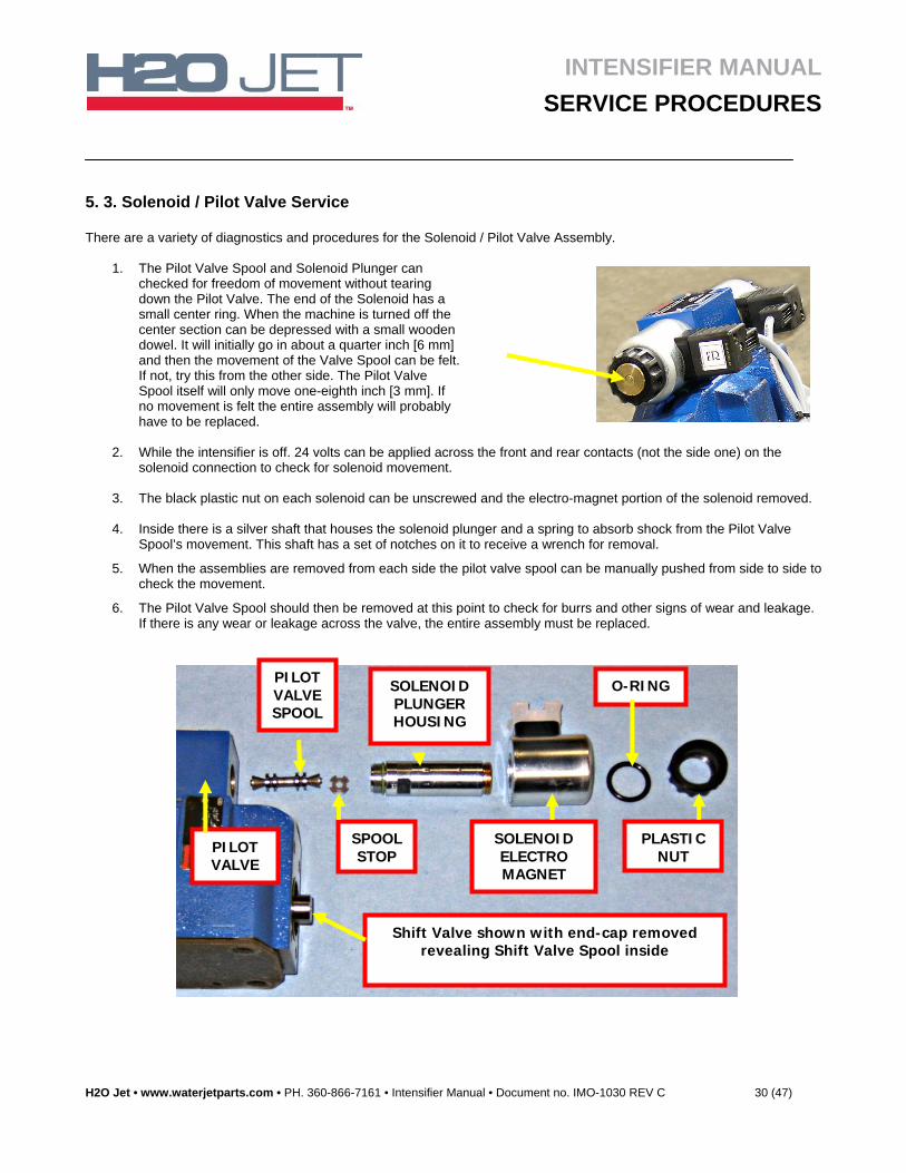
9. The Firing Pin should be approximately 1.150” [29.2 mm] long, have a shaft OD of approximately 0.082”[2.08 mm], and have no measurable bend. Firing Pins for Electric Shift units are silver colored; brass colored for Mechanical Shift units.
ACTUATING PIN
10. Inspect the Firing Pin bore in the End Bell. It must be polished and have no gouges, burrs, or other surface disruptions. It must not be elongated or egg shaped.
11. Replace the Firing Pin in the End Bell. a. Use the Firing Pin tool and a small Allen wrench b. Place the Firing Pin in the groove of the tool with the head toward the o-ring. c. Insert the too into the actuating plunger bore using the small Allen wrench to apply pressure against
the pin. d. Rotate the tool until the pin lines up with the Firing Pin Bore. The pressure applied will force the Firing
Pin into the bore. Visually check the pin to make sure it is correctly installed. 12. Insert the Actuator Pin Assembly, large end first, so the magnet faces the switch. 13. Install new switch and screw back into place. 14. Reconnect the switch cable 15. Torque the switch bolts to 140 – 160 in-lbs [16-18 Nm] 16. The directional shifting will probably have to be instructed which way to go at start-up. See the Operations
section of your pump manual, section 3.
Firing Pin
INTENSIFIER MANUAL
SERVICE PROCEDURES
H2O Jet • www.waterjetparts.com • PH. 360-866-7161 • Intensifier Manual • Document no. IMO-1030 REV C 30 (47)
5. 3. Solenoid / Pilot Valve Service There are a variety of diagnostics and procedures for the Solenoid / Pilot Valve Assembly.
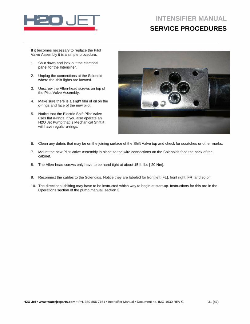
1. The Pilot Valve Spool and Solenoid Plunger can checked for freedom of movement without tearing down the Pilot Valve. The end of the Solenoid has a small center ring. When the machine is turned off the center section can be depressed with a small wooden dowel. It will initially go in about a quarter inch [6 mm] and then the movement of the Valve Spool can be felt. If not, try this from the other side. The Pilot Valve Spool itself will only move one-eighth inch [3 mm]. If no movement is felt the entire assembly will probably have to be replaced.
2. While the intensifier is off. 24 volts can be applied across the front and rear contacts (not the side one) on the
solenoid connection to check for solenoid movement.
3. The black plastic nut on each solenoid can be unscrewed and the electro-magnet portion of the solenoid removed.
4. Inside there is a silver shaft that houses the solenoid plunger and a spring to absorb shock from the Pilot Valve Spool’s movement. This shaft has a set of notches on it to receive a wrench for removal.
5. When the assemblies are removed from each side the pilot valve spool can be manually pushed from side to side to check the movement.
6. The Pilot Valve Spool should then be removed at this point to check for burrs and other signs of wear and leakage. If there is any wear or leakage across the valve, the entire assembly must be replaced.
PILOT VALVE
PILOT VALVE SPOOL
SOLENOID PLUNGER HOUSING
SOLENOID ELECTRO MAGNET
O-RING
PLASTIC NUT
SPOOL STOP
Shift Valve shown with end-cap removed revealing Shift Valve Spool inside
INTENSIFIER MANUAL
SERVICE PROCEDURES
H2O Jet • www.waterjetparts.com • PH. 360-866-7161 • Intensifier Manual • Document no. IMO-1030 REV C 31 (47)
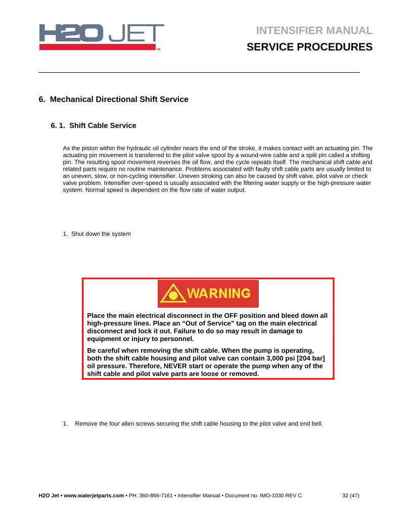
If it becomes necessary to replace the Pilot Valve Assembly it is a simple procedure. 1. Shut down and lock out the electrical
panel for the Intensifier. 2. Unplug the connections at the Solenoid
where the shift lights are located. 3. Unscrew the Allen-head screws on top of
the Pilot Valve Assembly. 4. Make sure there is a slight film of oil on the
o-rings and face of the new pilot. 5. Notice that the Electric Shift Pilot Valve
uses flat o-rings. If you also operate an H2O Jet Pump that is Mechanical Shift it will have regular o-rings.
6. Clean any debris that may be on the joining surface of the Shift Valve top and check for scratches or other marks. 7. Mount the new Pilot Valve Assembly in place so the wire connections on the Solenoids face the back of the
cabinet. 8. The Allen-head screws only have to be hand tight at about 15 ft. lbs [ 20 Nm].
9. Reconnect the cables to the Solenoids. Notice they are labeled for front left [FL], front right [FR] and so on. 10. The directional shifting may have to be instructed which way to begin at start-up. Instructions for this are in the
Operations section of the pump manual, section 3.
INTENSIFIER MANUAL
SERVICE PROCEDURES
H2O Jet • www.waterjetparts.com • PH. 360-866-7161 • Intensifier Manual • Document no. IMO-1030 REV C 32 (47)
6. Mechanical Directional Shift Service
6. 1. Shift Cable Service
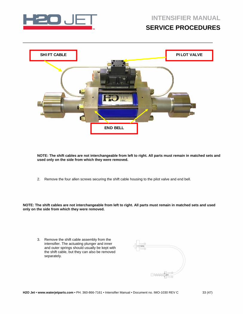
As the piston within the hydraulic oil cylinder nears the end of the stroke, it makes contact with an actuating pin. The actuating pin movement is transferred to the pilot valve spool by a wound-wire cable and a split pin called a shifting pin. The resulting spool movement reverses the oil flow, and the cycle repeats itself. The mechanical shift cable and related parts require no routine maintenance. Problems associated with faulty shift cable parts are usually limited to an uneven, slow, or non-cycling intensifier. Uneven stroking can also be caused by shift valve, pilot valve or check valve problem. Intensifier over-speed is usually associated with the filtering water supply or the high-pressure water system. Normal speed is dependent on the flow rate of water output.
1. Shut down the system
Place the main electrical disconnect in the OFF position and bleed down all high-pressure lines. Place an “Out of Service” tag on the main electrical disconnect and lock it out. Failure to do so may result in damage to equipment or injury to personnel.
Be careful when removing the shift cable. When the pump is operating, both the shift cable housing and pilot valve can contain 3,000 psi [204 bar] oil pressure. Therefore, NEVER start or operate the pump when any of the shift cable and pilot valve parts are loose or removed.
1. Remove the four allen screws securing the shift cable housing to the pilot valve and end bell.
INTENSIFIER MANUAL
SERVICE PROCEDURES
H2O Jet • www.waterjetparts.com • PH. 360-866-7161 • Intensifier Manual • Document no. IMO-1030 REV C 33 (47)
NOTE: The shift cables are not interchangeable from left to right. All parts must remain in matched sets and used only on the side from which they were removed.
2. Remove the four allen screws securing the shift cable housing to the pilot valve and end bell.
NOTE: The shift cables are not interchangeable from left to right. All parts must remain in matched sets and used only on the side from which they were removed.
3. Remove the shift cable assembly from the intensifier. The actuating plunger and inner and outer springs should usually be kept with the shift cable, but they can also be removed separately.
END BELL
SHIFT CABLE PILOT VALVE
INTENSIFIER MANUAL
SERVICE PROCEDURES
H2O Jet • www.waterjetparts.com • PH. 360-866-7161 • Intensifier Manual • Document no. IMO-1030 REV C 34 (47)
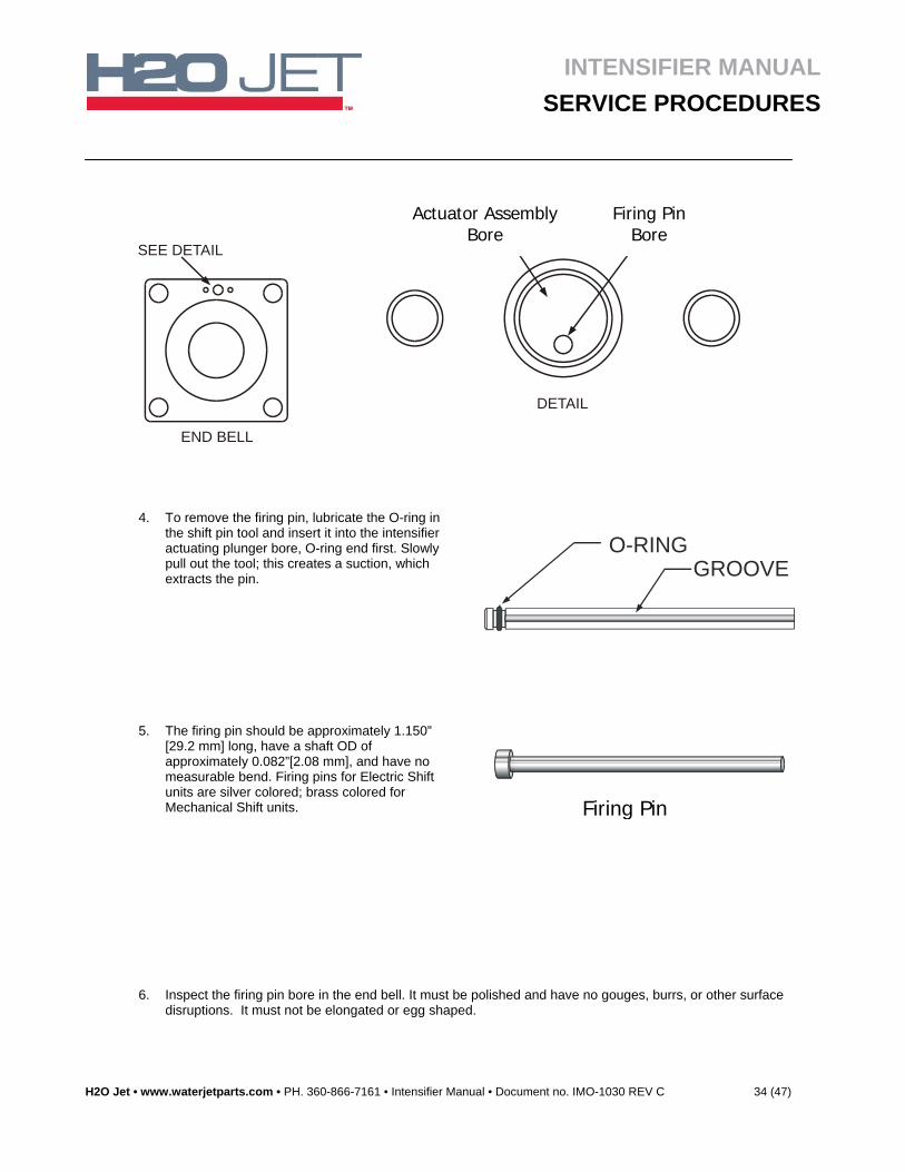
4. To remove the firing pin, lubricate the O-ring in the shift pin tool and insert it into the intensifier actuating plunger bore, O-ring end first. Slowly pull out the tool; this creates a suction, which extracts the pin.
O-RINGGROOVE
5. The firing pin should be approximately 1.150” [29.2 mm] long, have a shaft OD of approximately 0.082”[2.08 mm], and have no measurable bend. Firing pins for Electric Shift units are silver colored; brass colored for Mechanical Shift units.
ACTUATING PIN
6. Inspect the firing pin bore in the end bell. It must be polished and have no gouges, burrs, or other surface disruptions. It must not be elongated or egg shaped.
SEE DETAIL
ACTUATINGPLUNGER BORE
ACTUATINGPIN BORE
DETAIL
END BELL
Firing Pin
Firing Pin Bore
Actuator Assembly Bore
INTENSIFIER MANUAL
SERVICE PROCEDURES
H2O Jet • www.waterjetparts.com • PH. 360-866-7161 • Intensifier Manual • Document no. IMO-1030 REV C 35 (47)
7. Replace the firing pin in the end bell.
• Use the firing pin tool and a small allen wrench.
• Place the firing pin in the groove of the tool with the head toward the O-ring.
• Insert the tool into the actuating plunger bore, using the small Allen wrench to apply pressure against the pin.
• Rotate the tool until the pin lines up with the firing pin bore. The pressure applied will force the firing pin into the bore. Visually check the pin to make sure it is correctly installed.
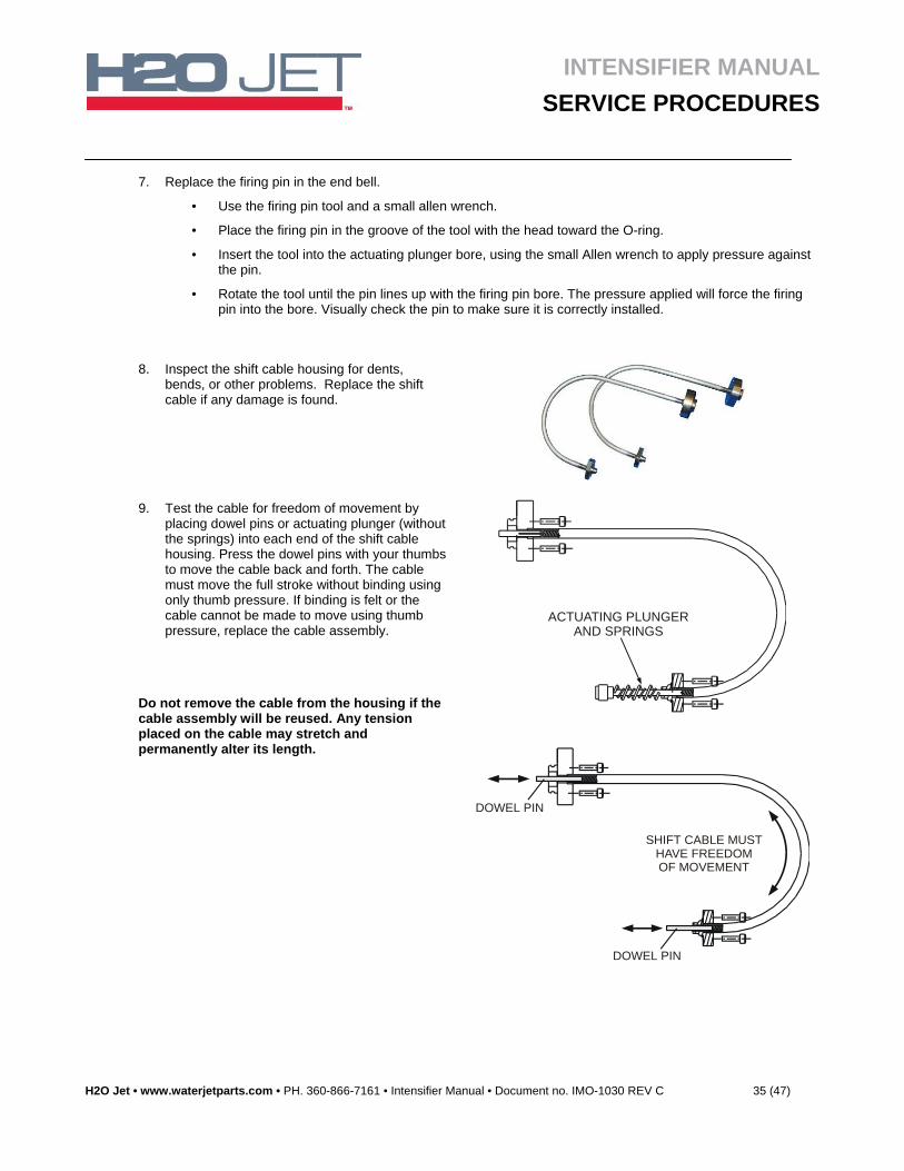
8. Inspect the shift cable housing for dents, bends, or other problems. Replace the shift cable if any damage is found.
9. Test the cable for freedom of movement by placing dowel pins or actuating plunger (without the springs) into each end of the shift cable housing. Press the dowel pins with your thumbs to move the cable back and forth. The cable must move the full stroke without binding using only thumb pressure. If binding is felt or the cable cannot be made to move using thumb pressure, replace the cable assembly.
Do not remove the cable from the housing if the cable assembly will be reused. Any tension placed on the cable may stretch and permanently alter its length.
ACTUATING PLUNGERAND SPRINGS
SHIFT CABLE MUSTHAVE FREEDOMOF MOVEMENT
DOWEL PIN
DOWEL PIN
INTENSIFIER MANUAL
SERVICE PROCEDURES
H2O Jet • www.waterjetparts.com • PH. 360-866-7161 • Intensifier Manual • Document no. IMO-1030 REV C 36 (47)
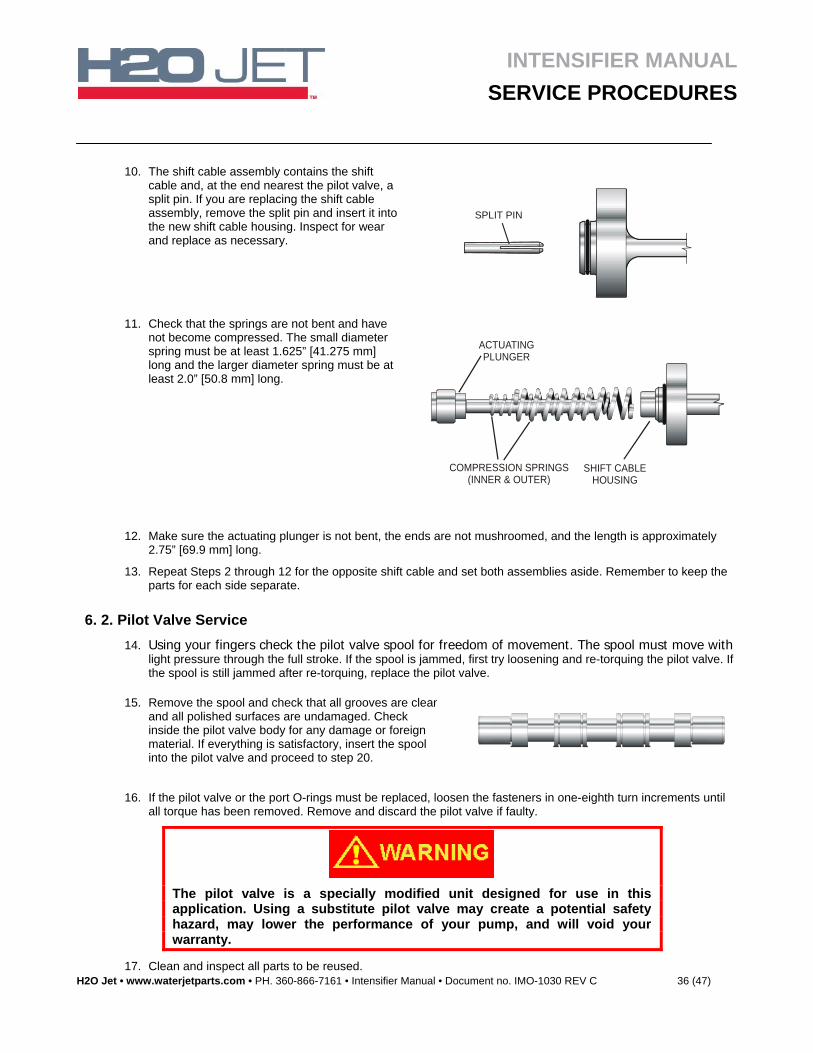
10. The shift cable assembly contains the shift cable and, at the end nearest the pilot valve, a split pin. If you are replacing the shift cable assembly, remove the split pin and insert it into the new shift cable housing. Inspect for wear and replace as necessary.
SPLIT PIN
11. Check that the springs are not bent and have not become compressed. The small diameter spring must be at least 1.625” [41.275 mm] long and the larger diameter spring must be at least 2.0” [50.8 mm] long.
ACTUATINGPLUNGER
SHIFT CABLEHOUSING
COMPRESSION SPRINGS(INNER & OUTER)
12. Make sure the actuating plunger is not bent, the ends are not mushroomed, and the length is approximately 2.75” [69.9 mm] long.
13. Repeat Steps 2 through 12 for the opposite shift cable and set both assemblies aside. Remember to keep the parts for each side separate.
6. 2. Pilot Valve Service
14. Using your fingers check the pilot valve spool for freedom of movement. The spool must move with light pressure through the full stroke. If the spool is jammed, first try loosening and re-torquing the pilot valve. If the spool is still jammed after re-torquing, replace the pilot valve.
15. Remove the spool and check that all grooves are cleanand all polished surfaces are undamaged. Check inside the pilot valve body for any damage or foreign material. If everything is satisfactory, insert the spool into the pilot valve and proceed to step 20.
16. If the pilot valve or the port O-rings must be replaced, loosen the fasteners in one-eighth turn increments until all torque has been removed. Remove and discard the pilot valve if faulty.
The pilot valve is a specially modified unit designed for use in this application. Using a substitute pilot valve may create a potential safety hazard, may lower the performance of your pump, and will void your warranty.
17. Clean and inspect all parts to be reused.
INTENSIFIER MANUAL
SERVICE PROCEDURES
H2O Jet • www.waterjetparts.com • PH. 360-866-7161 • Intensifier Manual • Document no. IMO-1030 REV C 37 (47)
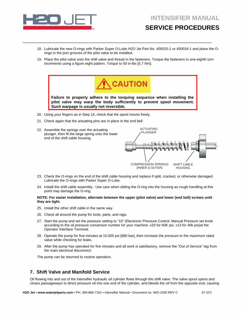
18. Lubricate the new O-rings with Parker Super O-Lube H2O Jet Part No. 400015-1 or 400034-1 and place the O-rings in the port grooves of the pilot valve to be installed.
19. Place the pilot valve onto the shift valve and thread in the fasteners. Torque the fasteners in one-eighth turn increments using a figure eight pattern. Torque to 50 in-lbs [5.7 Nm].
Failure to properly adhere to the torquing sequence when installing the pilot valve may warp the body sufficiently to prevent spool movement. Such warpage is usually not reversible.
20. Using your fingers as in Step 14, check that the spool moves freely.
21. Check again that the actuating pins are in place in the end bell.
22. Assemble the springs over the actuating plunger, then fit the large spring onto the lower end of the shift cable housing.
ACTUATINGPLUNGER
SHIFT CABLEHOUSING
COMPRESSION SPRINGS(INNER & OUTER)
23. Check the O-rings on the end of the shift cable housing and replace if split, cracked, or otherwise damaged. Lubricate the O-rings with Parker Super O-Lube.
24. Install the shift cable assembly. Use care when sliding the O-ring into the housing as rough handling at this point may damage the O-ring.
NOTE: For easier installation, alternate between the upper (pilot valve) and lower (end bell) screws until they are tight.
25. Install the other shift cable in the same way.
26. Check all around the pump for tools, parts, and rags.
27. Start the pump and set the pressure setting to “10” (Electronic Pressure Control, Manual Pressure set knob according to the oil pressure conversion number for your machine; x20 for 60K psi, x13 for 40k psi)at the Operator Interface Terminal.
28. Operate the pump for five minutes at 10,000 psi [680 bar], then increase the pressure to the maximum rated value while checking for leaks.
29. After the pump has operated for five minutes and all work is satisfactory, remove the “Out of Service” tag from the main electrical disconnect.
The pump can be returned to routine operation.
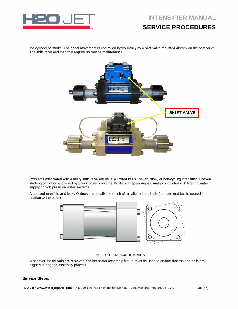
7. Shift Valve and Manifold Service
Oil flowing into and out of the intensifier hydraulic oil cylinder flows through the shift valve. The valve spool opens and closes passageways to direct pressure oil into one end of the cylinder, and bleeds the oil from the opposite end, causing
INTENSIFIER MANUAL
SERVICE PROCEDURES
H2O Jet • www.waterjetparts.com • PH. 360-866-7161 • Intensifier Manual • Document no. IMO-1030 REV C 38 (47)
the cylinder to stroke. The spool movement is controlled hydraulically by a pilot valve mounted directly on the shift valve. The shift valve and manifold require no routine maintenance.
Problems associated with a faulty shift valve are usually limited to an uneven, slow, or non-cycling intensifier. Uneven stroking can also be caused by check valve problems. While over speeding is usually associated with filtering water supply or high pressure water systems.
A cracked manifold and leaky O-rings are usually the result of misaligned end bells (i.e., one end bell is rotated in relation to the other).
END BELL MIS-ALIGNMENT Whenever the tie rods are removed, the intensifier assembly fixture must be used to ensure that the end bells are aligned during the assembly process.
Service Steps:
SHIFT VALVE
INTENSIFIER MANUAL
SERVICE PROCEDURES
H2O Jet • www.waterjetparts.com • PH. 360-866-7161 • Intensifier Manual • Document no. IMO-1030 REV C 39 (47)
1. Shut down the system.
Place the main electrical disconnect in the OFF position and bleed down all high-pressure lines. Place an “Out of Service” tag on the main electrical disconnect and lock it out. Failure to do so may result in damage to equipment or injury to personnel.
When the pump is operating, the shift valve may contain 3,000 psi [207 bar] oil pressure. Therefore, NEVER start or operate the pump when any of the shift valve parts are loose or removed.
2. Remove the four cap screws that secure the end cover to the shift valve. Remove the other end cover.
3. Using your fingers, check the shift valve spool for freedom of movement. The spool must move with light pressure through the full stroke. If the spool is jammed, the valve must be replaced.
If you are replacing the spool valve, skip to Step 6.
4. Remove the spool and check that all grooves in the spool are clean and all polished surfaces are undamaged. Check the inside of the shift valve body for any damage or foreign material. If everything is satisfactory, insert the spool into the shift valve.
5. If the shift valve and manifold are satisfactory, replace the end cap. You need not follow this procedure any further.
The shift valve is a specially modified unit designed for use in this application. Using a substitute shift valve may create a potential safety hazard, may lower the performance of your pump, and will void your warranty.
6. If the shift valve or port O-rings must be replaced, remove the shift cable and pilot valve and set them aside. See the “Shift Cable and Pilot Valve Service” for the correct procedure.
7. Loosen the fasteners in one-eighth turn increments until all torque has been removed. Remove the shift valve and discard it if faulty.
8. Check the manifold and O-rings. If they are not in need of service, proceed to Step 23. If the manifold or O-rings need service continue with step 9.
9. Disconnect the oil supply and return lines from the manifold; cap the lines with the plugs supplied with the pump.
10. Disconnect the water supply lines at the quick-disconnects.
11. Remove the pressure relief valve and set aside. Use a Spanner wrench [400025-1] to make removal easier.
12. Disconnect the small diameter, hydraulic high-pressure line connected to the manifold. Move the high-pressure lines out of the way.
13. Loosen the cap screws mounting the manifold to the intensifier in one-eighth turn increments.
14. Remove the cap screws mounting the manifold to the frame and remove the manifold.
INTENSIFIER MANUAL
SERVICE PROCEDURES
H2O Jet • www.waterjetparts.com • PH. 360-866-7161 • Intensifier Manual • Document no. IMO-1030 REV C 40 (47)
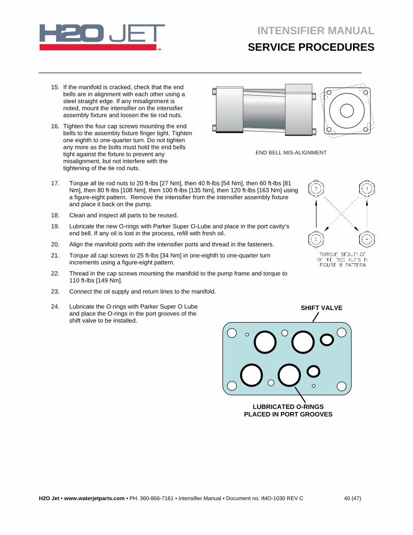
15. If the manifold is cracked, check that the end bells are in alignment with each other using a steel straight edge. If any misalignment is noted, mount the intensifier on the intensifier assembly fixture and loosen the tie rod nuts.
16. Tighten the four cap screws mounting the end bells to the assembly fixture finger tight. Tighten one eighth to one-quarter turn. Do not tighten any more as the bolts must hold the end bells tight against the fixture to prevent any misalignment, but not interfere with the tightening of the tie rod nuts.
END BELL MIS-ALIGNMENT
17. Torque all tie rod nuts to 20 ft-lbs [27 Nm], then 40 ft-lbs [54 Nm], then 60 ft-lbs [81 Nm], then 80 ft-lbs [108 Nm], then 100 ft-lbs [135 Nm], then 120 ft-lbs [163 Nm] using a figure-eight pattern. Remove the intensifier from the intensifier assembly fixture and place it back on the pump.
18. Clean and inspect all parts to be reused.
19. Lubricate the new O-rings with Parker Super O-Lube and place in the port cavity’s end bell. If any oil is lost in the process, refill with fresh oil.
20. Align the manifold ports with the intensifier ports and thread in the fasteners.
21. Torque all cap screws to 25 ft-lbs [34 Nm] in one-eighth to one-quarter turn increments using a figure-eight pattern.
22. Thread in the cap screws mounting the manifold to the pump frame and torque to 110 ft-lbs [149 Nm].
23. Connect the oil supply and return lines to the manifold.
24. Lubricate the O-rings with Parker Super O Lube and place the O-rings in the port grooves of the shift valve to be installed.
SHIFT VALVE
LUBRICATED O-RINGS PLACED IN PORT GROOVES
INTENSIFIER MANUAL
SERVICE PROCEDURES
H2O Jet • www.waterjetparts.com • PH. 360-866-7161 • Intensifier Manual • Document no. IMO-1030 REV C 41 (47)
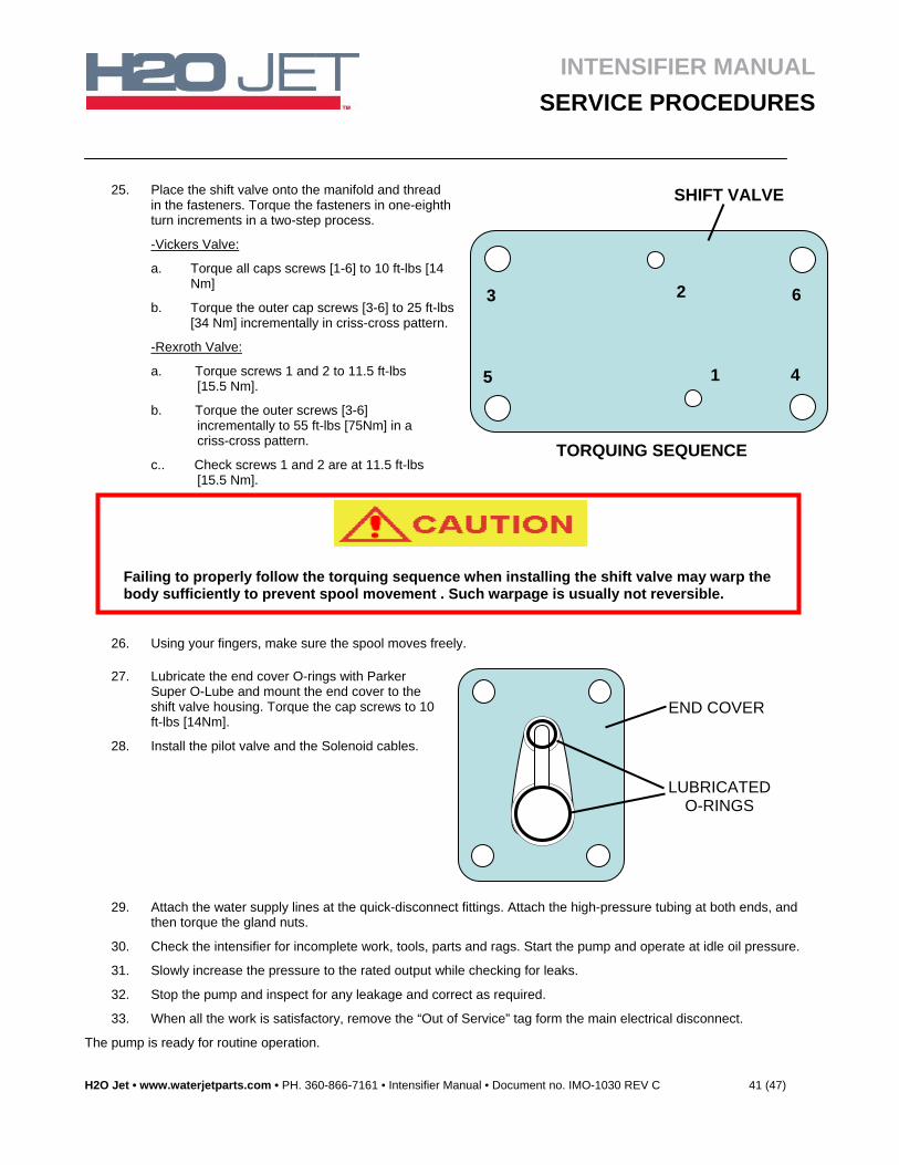
25. Place the shift valve onto the manifold and thread in the fasteners. Torque the fasteners in one-eighth turn increments in a two-step process.
-Vickers Valve:
a. Torque all caps screws [1-6] to 10 ft-lbs [14 Nm]
b. Torque the outer cap screws [3-6] to 25 ft-lbs [34 Nm] incrementally in criss-cross pattern.
-Rexroth Valve:
a. Torque screws 1 and 2 to 11.5 ft-lbs [15.5 Nm].
b. Torque the outer screws [3-6] incrementally to 55 ft-lbs [75Nm] in a criss-cross pattern.
c.. Check screws 1 and 2 are at 11.5 ft-lbs [15.5 Nm].
26. Using your fingers, make sure the spool moves freely.
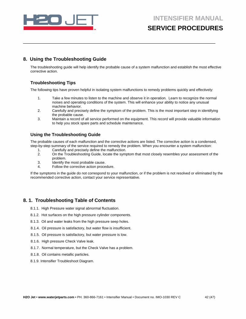
27. Lubricate the end cover O-rings with Parker Super O-Lube and mount the end cover to the shift valve housing. Torque the cap screws to 10 ft-lbs [14Nm].
28. Install the pilot valve and the Solenoid cables.
29. Attach the water supply lines at the quick-disconnect fittings. Attach the high-pressure tubing at both ends, and then torque the gland nuts.
30. Check the intensifier for incomplete work, tools, parts and rags. Start the pump and operate at idle oil pressure.
31. Slowly increase the pressure to the rated output while checking for leaks.
32. Stop the pump and inspect for any leakage and correct as required.
33. When all the work is satisfactory, remove the “Out of Service” tag form the main electrical disconnect.
The pump is ready for routine operation.
5
6
41
2 3
SHIFT VALVE
TORQUING SEQUENCE
END COVER
LUBRICATEDO-RINGS
Failing to properly follow the torquing sequence when installing the shift valve may warp the body sufficiently to prevent spool movement . Such warpage is usually not reversible.
INTENSIFIER MANUAL
SERVICE PROCEDURES
H2O Jet • www.waterjetparts.com • PH. 360-866-7161 • Intensifier Manual • Document no. IMO-1030 REV C 42 (47)
8. Using the Troubleshooting Guide
The troubleshooting guide will help identify the probable cause of a system malfunction and establish the most effective corrective action.
Troubleshooting Tips
The following tips have proven helpful in isolating system malfunctions to remedy problems quickly and effectively:
1. Take a few minutes to listen to the machine and observe it in operation. Learn to recognize the normal noises and operating conditions of the system. This will enhance your ability to notice any unusual machine behavior.
2. Carefully and precisely define the symptom of the problem. This is the most important step in identifying the probable cause.
3. Maintain a record of all service performed on the equipment. This record will provide valuable information to help you stock spare parts and schedule maintenance.
Using the Troubleshooting Guide
The probable causes of each malfunction and the corrective actions are listed. The corrective action is a condensed, step-by-step summary of the service required to remedy the problem. When you encounter a system malfunction:
1. Carefully and precisely define the malfunction. 2. On the Troubleshooting Guide, locate the symptom that most closely resembles your assessment of the
problem. 3. Identify the most probable cause. 4. Follow the corrective action procedure.
If the symptoms in the guide do not correspond to your malfunction, or if the problem is not resolved or eliminated by the recommended corrective action, contact your service representative.
8. 1. Troubleshooting Table of Contents
8.1.1. High Pressure water signal abnormal fluctuation.
8.1.2. Hot surfaces on the high pressure cylinder components.
8.1.3. Oil and water leaks from the high pressure seep holes.
8.1.4. Oil pressure is satisfactory, but water flow is insufficient.
8.1.5. Oil pressure is satisfactory, but water pressure is low.
8.1.6. High pressure Check Valve leak.
8.1.7. Normal temperature, but the Check Valve has a problem.
8.1.8. Oil contains metallic particles.
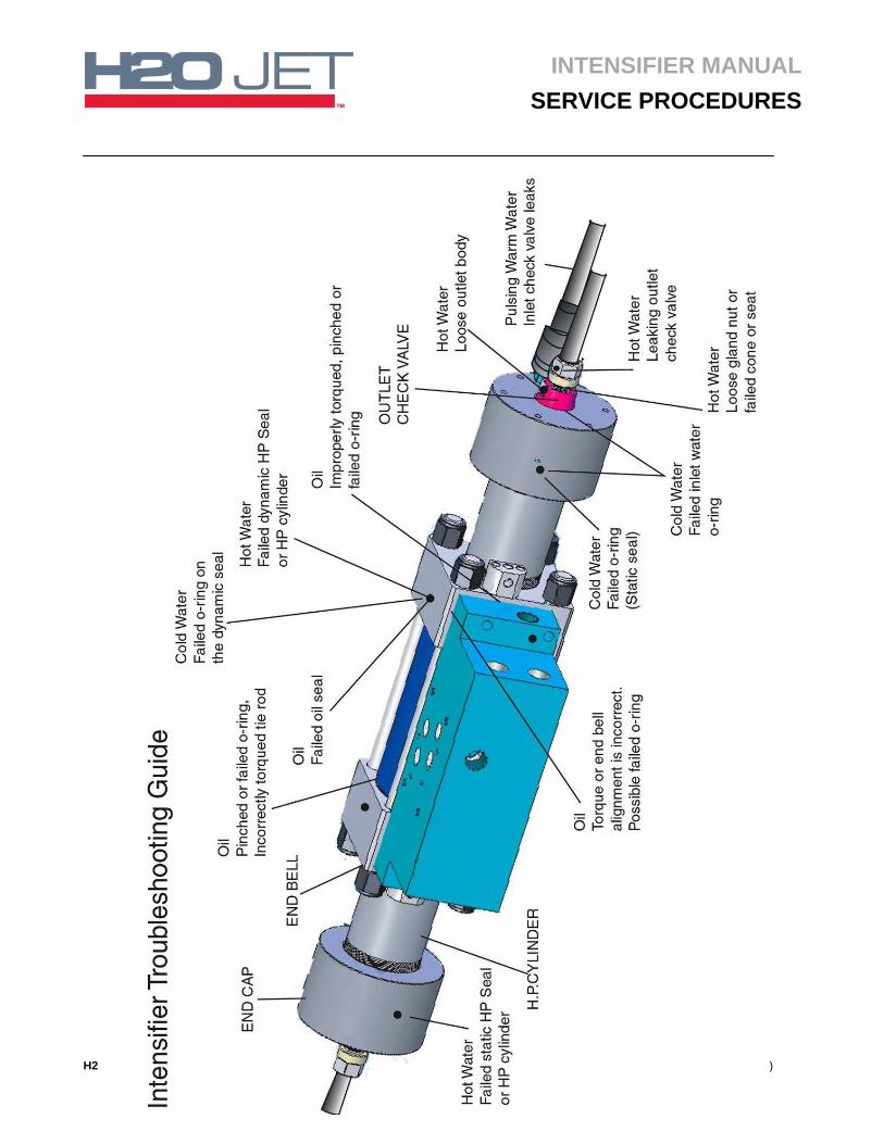
8.1.9. Intensifier Troubleshoot Diagram.
INTENSIFIER MANUAL
SERVICE PROCEDURES
H2O Jet • www.waterjetparts.com • PH. 360-866-7161 • Intensifier Manual • Document no. IMO-1030 REV C 43 (47)
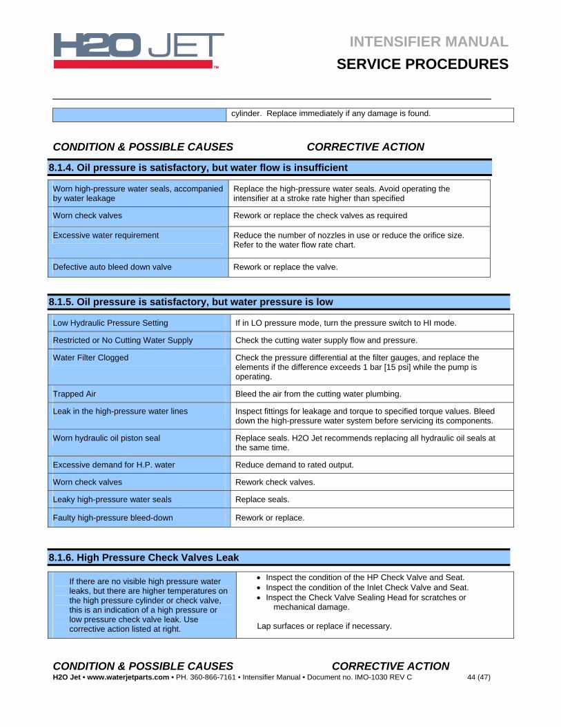
8. 2. Troubleshooting Guide CONDITION & POSSIBLE CAUSES CORRECTIVE ACTION
8.1.1. High Pressure Water Signal Abnormal Fluctuation
Orifice Large/Worn/Damaged Check to see that the orifices do not exceed the capacity of the pump.
Check to see that the orifices are in good working order and that the orifice is not missing.
Check Piping Leaks Check system components for leaks including the dump valve condition.
Check Valve Leakage Inspect the high pressure outlet check valves.
Inspect the low pressure inlet check valves.
Check Seal Leakage Inspect the plunger, sealing head seals.
Hydraulic Control Malfunction Check the hydraulic valves operation.
Verify that the 4-way reversing valve is shifting properly.
Verify that the proximity switch is properly installed.
8.1.2. Hot Surfaces on the High Pressure Cylinder Components
H. P. Discharge Check Leaking Inspect the check valve seat, poppet, spring and guide condition.
Low Pressure Inlet Inspect the check valve inlet poppet and seat.
Plunger Check the plunger seal for leaks and check the plunger for wear. Replace if necessary.
Damaged High Pressure Cylinder Check the cylinder inside diameter for damage. Replace if any damage is found.
8.1.3. Oil and Water Leaks from the High Pressure Weep Holes
Oil Leak at H. P. Intensifier Check the hydraulic cylinder O-ring for leakage.
Check the proximity switch area for oil leakage.
Remove, inspect, replace or clean hydraulic seal.
Water Leak at the H. P. Plunger Seal Replace the seal assembly.
Check the plunger and follower if the leak is greater than 1 drop in 10 strokes.
Check for scratches, circumferential or longitudinal grooves, or material build up on inside diameter of the High pressure cylinder. Replace immediately if any damage is found.
Water Leaks at the Sealing Head Seal Check the seal assembly.
Check for scratches on the inside diameter of the High Pressure
INTENSIFIER MANUAL
SERVICE PROCEDURES
H2O Jet • www.waterjetparts.com • PH. 360-866-7161 • Intensifier Manual • Document no. IMO-1030 REV C 44 (47)
cylinder. Replace immediately if any damage is found.
CONDITION & POSSIBLE CAUSES CORRECTIVE ACTION
8.1.4. Oil pressure is satisfactory, but water flow is insufficient
Worn high-pressure water seals, accompanied by water leakage
Replace the high-pressure water seals. Avoid operating the intensifier at a stroke rate higher than specified
Worn check valves Rework or replace the check valves as required
Excessive water requirement Reduce the number of nozzles in use or reduce the orifice size. Refer to the water flow rate chart.
Defective auto bleed down valve Rework or replace the valve.
8.1.5. Oil pressure is satisfactory, but water pressure is low
Low Hydraulic Pressure Setting If in LO pressure mode, turn the pressure switch to HI mode.
Restricted or No Cutting Water Supply Check the cutting water supply flow and pressure.
Water Filter Clogged Check the pressure differential at the filter gauges, and replace the elements if the difference exceeds 1 bar [15 psi] while the pump is operating.
Trapped Air Bleed the air from the cutting water plumbing.
Leak in the high-pressure water lines Inspect fittings for leakage and torque to specified torque values. Bleed down the high-pressure water system before servicing its components.
Worn hydraulic oil piston seal Replace seals. H2O Jet recommends replacing all hydraulic oil seals at the same time.
Excessive demand for H.P. water Reduce demand to rated output.
Worn check valves Rework check valves.
Leaky high-pressure water seals Replace seals.
Faulty high-pressure bleed-down Rework or replace.
8.1.6. High Pressure Check Valves Leak
If there are no visible high pressure water leaks, but there are higher temperatures on the high pressure cylinder or check valve, this is an indication of a high pressure or low pressure check valve leak. Use corrective action listed at right.
Inspect the condition of the HP Check Valve and Seat. Inspect the condition of the Inlet Check Valve and Seat. Inspect the Check Valve Sealing Head for scratches or
mechanical damage.
Lap surfaces or replace if necessary.
CONDITION & POSSIBLE CAUSES CORRECTIVE ACTION
INTENSIFIER MANUAL
SERVICE PROCEDURES
H2O Jet • www.waterjetparts.com • PH. 360-866-7161 • Intensifier Manual • Document no. IMO-1030 REV C 45 (47)
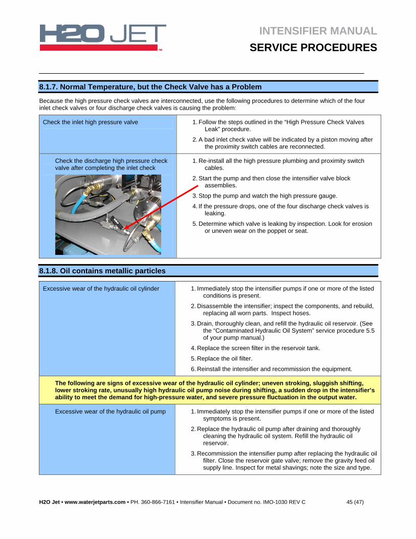
8.1.7. Normal Temperature, but the Check Valve has a Problem
Because the high pressure check valves are interconnected, use the following procedures to determine which of the four inlet check valves or four discharge check valves is causing the problem:
Check the inlet high pressure valve 1. Follow the steps outlined in the “High Pressure Check Valves Leak” procedure.
2. A bad inlet check valve will be indicated by a piston moving after the proximity switch cables are reconnected.
Check the discharge high pressure check valve after completing the inlet check
1. Re-install all the high pressure plumbing and proximity switch cables.
2. Start the pump and then close the intensifier valve block assemblies.
3. Stop the pump and watch the high pressure gauge.
4. If the pressure drops, one of the four discharge check valves is leaking.
5. Determine which valve is leaking by inspection. Look for erosion or uneven wear on the poppet or seat.
8.1.8. Oil contains metallic particles
Excessive wear of the hydraulic oil cylinder 1. Immediately stop the intensifier pumps if one or more of the listed conditions is present.
2. Disassemble the intensifier; inspect the components, and rebuild, replacing all worn parts. Inspect hoses.
3. Drain, thoroughly clean, and refill the hydraulic oil reservoir. (See the “Contaminated Hydraulic Oil System” service procedure 5.5 of your pump manual.)
4. Replace the screen filter in the reservoir tank.
5. Replace the oil filter.
6. Reinstall the intensifier and recommission the equipment.
The following are signs of excessive wear of the hydraulic oil cylinder; uneven stroking, sluggish shifting, lower stroking rate, unusually high hydraulic oil pump noise during shifting, a sudden drop in the intensifier’s ability to meet the demand for high-pressure water, and severe pressure fluctuation in the output water.
Excessive wear of the hydraulic oil pump 1. Immediately stop the intensifier pumps if one or more of the listed symptoms is present.
2. Replace the hydraulic oil pump after draining and thoroughly cleaning the hydraulic oil system. Refill the hydraulic oil reservoir.
3. Recommission the intensifier pump after replacing the hydraulic oil filter. Close the reservoir gate valve; remove the gravity feed oil supply line. Inspect for metal shavings; note the size and type.
INTENSIFIER MANUAL
SERVICE PROCEDURES
H2O Jet • www.waterjetparts.com • PH. 360-866-7161 • Intensifier Manual • Document no. IMO-1030 REV C 46 (47)
INTENSIFIER MANUAL
SERVICE PROCEDURES
H2O Jet • www.waterjetparts.com • PH. 360-866-7161 • Intensifier Manual • Document no. IMO-1030 REV C 47 (47)
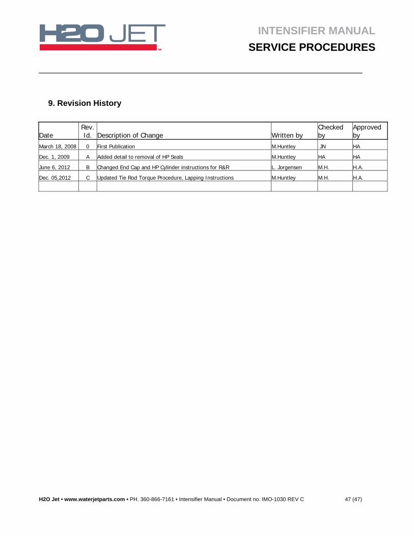
9. Revision History
Date Rev. Id. Description of Change Written by
Checked by
Approved by
March 18, 2008 0 First Publication M.Huntley JN HA
Dec. 1, 2009 A Added detail to removal of HP Seals M.Huntley HA HA
June 6, 2012 B Changed End Cap and HP Cylinder instructions for R&R L. Jorgensen M.H. H.A.
Dec. 05,2012 C Updated Tie Rod Torque Procedure, Lapping Instructions M.Huntley M.H. H.A.