Embed Size (px)
Citation preview
7/127/12
7/12
7/12
7/12
7/12
7/12
7/12
7/12
7/1212'9"4
8'
4'2"12
22'8"12'8"
47'5"10
11'2"6
58'8"
1'11
"42'2'2'2'2'2'2'2'2'2'2'2'2'2'2'2'2'2'2'2'2'2'2'2'2'2'2'2'7"4
42'8
"
50'8
"
10'
6'
74'
10'7"15
8"4
11'3
"12
1"8
11'3
"12
14'8
"9'
4"14
'8"
21'4
"
45'4
"30
'
3'4"
26'8
"13
'4"
16'8
"15
'4"
75'4
"
2'8"
16'12'19'5"1011'2"6
30'12'9"411'10"910'8"32'8"
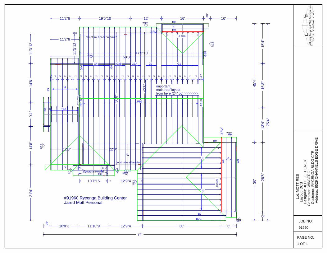
importantmain roof layoutfrom here (24" oc) >>>>>>>
OD
D S
PAC
E
no structural header
structural header required
#91960 Rycenga Building CenterJared Mott Personal
HU
S26
Structural Header
HUS26
AX AG
3 PL
Y
3 PLY
BM
B2G
B2
CG
V
D
DG
DX
FFGH
G
PB1G
G4G
PB1G
G1G
A
B1B
C
PB2
H
PB1
G1G2G3AG3BG4
G4
PAGE NO:
1 OF 1
JOB NO:
91960
Lot
: MO
TT R
ES
Lay
out:
DC
S
Des
igne
r: JE
FF L
ETH
ERER
Con
tract
or: W
INBE
RG
C
usto
mer
: RYC
ENG
A BL
DG
CTR
A
ddre
ss: 8
529
CH
ANN
ELS
EDG
E D
RIV
E

Job:(91960) / -RYCENGA BLDG CTR /MOTT RES / G4G 50'8" Gable This dwg. prepared by the ITW job designer program from truss mfr's layout.Top chord 2x6 SPF 1650f-1.5EBot chord 2x6 SPF 1650f-1.5E :B1 2x6 SP 2700f-2.0E: Webs 2x4 SPF Stud:W3, W6, W10, W19, W20 2x4 SPF #1/#2: :W9, W13, W15, W16, W17 2x4 SPF #3::Rt Slider 2x8 SPF #1/#2: BLOCK LENGTH = 2.500'
All plates are 1.5X4 except as noted. Brg blocks:0.131"x3", min. nailsbrg x-loc #blocks length/blk #nails/blk wall plate 2 42.333' 1 17" 23 SP StandardBrg block to be same size and species as chord.Refer to drawing CNNAILSP1014 for more information.
(**) 1 plate(s) require special positioning. Refer to scaled plate plotdetails for special positioning requirements.
115 mph wind, 15.04 ft mean hgt, ASCE 7-10, CLOSED bldg,Located anywhere in roof, RISK CAT II, EXP B, wind TC DL=4.2 psf,wind BC DL=6.0 psf.
Wind loads and reactions based on MWFRS with additional C&Cmember design.
Right cantilever is exposed to wind Truss designed to support 0-0-0 top chord outlookers and claddingload not to exceed 0.05 PSF one face and 24.0" span opposite face.Top chord must not be cut or notched.See DWGS A11530ENC101014, GBLLETIN1014, & GABRST101014
for gable wind bracing requirements.(b) scab reinforcement. 80% length of web member. Same size,species & grade or better. Attach with 10d Box or Gun(0.128"x3",min.)nails @ 6" OC.
(a) 2 SCAB reinforcing members. 80% length of web member. Samesize, species & grade or better. Attach one to each face w/10d Boxor Gun (0.128"x3",min.) nails @ 6" OC.
Truss passed check for 20 psf additional bottom chord live load inareas with 42"-high x 24"-wide clearance.
Bottom chord checked for 10.00 psf non-concurrent bottom chordlive load applied per IBC-15 section 1607.
PLT TYP. WAVEDESC = G4G 50'8" Gable
DESIGN CRIT=IBC 2015 /TPI-2014 FT/RT=3%(0%)/0(0) PLY= 1 QTY= 1 REV. 16.02.01A.0117.21
Maximum Reactions (lbs), or *=PLFLoc R / U / Rw / Rh / RL / W
AP*478 / - / 97 / - / 16 / 139AB 4958 / - / 1086 / - / - / 4.0Wind reactions based on MWFRSAP Min Brg Width Req = -AB Min Brg Width Req = -Bearings AP & AB Fcperp = 565psi.
Maximum Top Chord Forces Per Ply (lbs)Chords Tens.Comp.
A - B 218 0B - C 36 - 508C - D 59 - 360D - E 54 - 371E - F 68 - 359F - G 71 - 283G - H 89 - 305H - I 94 - 253I - J 112 - 367J - K 178 - 1693K - L 189 - 1687L - M 216 - 1546M - N 230 - 1486
Chords Tens. Comp.
N - O 265 - 2105O - P 265 - 2105P - Q 266 - 2120Q - R 266 - 2119R - S 265 - 2104S - T 265 - 2102T - U 255 - 2224U - V 239 - 2116V - W 162 - 1082W - X 151 - 1154X - Y 1491 - 113Y - Z 835 - 92Z -AA 553 - 217
Maximum Bot Chord Forces Per Ply (lbs)Chords Tens.Comp.
AP-AO 185 - 172AO-AN 253 - 92AN-AM 241 - 92AM-AL 232 - 92AL-AK 232 - 92AK-AJ 457 - 74AJ-AI 507 - 70AI-AH 507 - 70
Chords Tens. Comp.
AH-AG 1673 0AG-AF 1753 0AF-AE 1753 0AE-AD 965 - 26AD-AC 965 - 26AC-AB 193 - 990AB-AA 104 - 446
**WARNING** READ AND FOLLOW ALL NOTES ON THIS DRAWING!**IMPORTANT** FURNISH THIS DRAWING TO ALL CONTRACTORS INCLUDING THE INSTALLERSTrusses require extreme care in fabricating, handling, shipping, installing and bracing. Refer to and follow the latest edition of BCSI (BuildingComponent Safety Information, by TPI and SBCA) for safety practices prior to performing these functions. Installers shall provide temporarybracing per BCSI. Unless noted otherwise,top chord shall have properly attached structural sheathing and bottom chord shall have a properlyattached rigid ceiling. Locations shown for permanent lateral restraint of webs shall have bracing installed per BCSI sections B3, B7, or B10,as applicable. Apply plates to each face of truss and position as shown above and on the Joint Details, unless noted otherwise. Refer todrawings 160A-Z for standard plate positions.
ITW Building Components Group Inc. shall not be responsible for any deviation from this drawing,any failure to build the truss in conformancewith ANSI/TPI 1, or for handling, shipping, installation and bracing of trusses.A seal on this drawing or cover page listing this drawing, indicates acceptance of professional engineeringresponsibility solely for the design shown.The suitability and use of this drawing for any structure is the responsibility of the Building Designer per ANSI/TPI 1 Sec.2.
TC LL 47.00 PSF
TC DL 7.00 PSF
BC DL 10.00 PSF
BC LL 0.00 PSF
TOT. LD 64.00 PSF
DUR. FAC 1.15
SPACING 24.0 "
JOB #: 91960DATE - 07/08/17
G4G 50'8" Gable
WEIGHT =539.1
SEQ - 110354
TYPE GABL
BL1(a)
(a) (b) (a) (b) (b)
(b)(b)
A
B
CD
EF
GHI
JK
LM N O P Q R S T U
V
WX
Y
ZAA
ABACADAEAFAGAHAIAJAKALAMANAOAP
AQAR
AS ATAU
AV
AW
AX
AYAZBA
BB
BC
BD
BEBF
BG
BH
BI
BJ
BK
BLBM
BN
BO
712
3X4(R)
2X63X4
5X6
2X4 4X4(R)
3X4
6X8
5X6
2X4
4X6(R)
7X8(R)
3X43X4
3X6
2X4
3X43X4
4X8 5X6
7X8
4X6 5X6
4X8
5X8(R)
5X65X8(**)
6X8(R)
3X4
4X4(E3)3X10(E3)
41'11"12 8'
2'7"122'(TYP)
4'
7'7"87'7"8
11'5"123'10"4
17'8"46'2"8
20'7"122'11"8
24'7"124' 28'10"13
4'3"1
31'7"42'8"7 37'8"
6'0"1241'8"
4'
45'2"113'6"11 49'11"12
4'9"1
11'5"1211'5"12
17'9"126'4"
24'7"126'10"
31'5"126'10"
37'8"6'2"4
41'8"4'
49'11"128'3"122'8"4
1'6"13 1'2"
11'1
0"10
12'3
"10

Job:(91960) / -RYCENGA BLDG CTR /MOTT RES / G4G 50'8" Gable This dwg. prepared by the ITW job designer program from truss mfr's layout.In lieu of structural panels or rigid ceiling use purlinsto laterally brace chords as follows: CHORD SPACING(IN OC) START(FT) END(FT) TC 24 18.44 32.23 BC 75 0.69 50.67Apply purlins to any chords above or below fillersat 24" OC unless shown otherwise above.
Deflection meets L/360 live and L/240 total load. Creep increasefactor for dead load is 2.00.
WARNING: Furnish a copy of this DWG to the installation contractor.Special care must be taken during handling, shipping and installationof trusses. See "WARNING" note below.
Truss designed for unbalanced snow load based on Pg=60.00 psf,Ct=1.10, Ce=1.00, CAT II & Pf=46.20 psf.
PLT TYP. WAVEDESC = G4G 50'8" Gable
DESIGN CRIT=IBC 2015 /TPI-2014 FT/RT=3%(0%)/0(0) PLY= 1 QTY= 1 REV. 16.02.01A.0117.21
Maximum Web Forces Per Ply (lbs)Webs Tens.Comp.
B -AP 109 - 1123B -AO 284 - 86F -AQ 50 - 93AR-AS 95 - 54AK-AT 19 - 344AS-AT 59 - 423AT-AJ 57 - 384AJ-AU 137 - 2534AU- J 121 - 2368AU-AW 26 - 287J -AV 1774 - 15AW-AZ 24 - 250AX-AY 1769 - 16AZ-BB 16 - 252BA-BB 1858 - 4BC-BD 149 - 340BC-AH 1822 0BD-BF 238 - 310AH-BF 65 - 1356N -BE 50 - 1233
Webs Tens. Comp.
N -BG 1419 - 78BE-BH 156 - 389BH-BK 172 - 334BI-BJ 1476 - 84BJ-BK 1116 - 57BK-BL 216 - 128BK-AG 1057 - 53BL-BN 230 - 107AG- U 911 - 38R -BM 137 - 1540BM-BO 210 - 169BN-AG 144 - 1635BO- T 228 - 121U -AE 95 - 900AE- V 1261 - 21V -AC 181 - 2338AC- X 2839 - 119X -AB 226 - 4124AB- Y 137 - 960
Maximum Gable Forces Per Ply (lbs)Gables Tens.Comp.
AO- C 33 - 192D -AN 68 - 506E -AM 33 - 402AQ- G 30 - 362AL-AR 31 - 423AS- I 24 - 456K -AV 2 - 80AW-AX 3 - 77
Gables Tens. Comp.
L -AY 129 - 488AZ-BA 23 - 185M -BD 16 - 182BG- O 7 - 46BH-BI 5 - 111BJ- P 33 - 430Q -BL 6 - 54S -BO 8 - 93
**WARNING** READ AND FOLLOW ALL NOTES ON THIS DRAWING!**IMPORTANT** FURNISH THIS DRAWING TO ALL CONTRACTORS INCLUDING THE INSTALLERSTrusses require extreme care in fabricating, handling, shipping, installing and bracing. Refer to and follow the latest edition of BCSI (BuildingComponent Safety Information, by TPI and SBCA) for safety practices prior to performing these functions. Installers shall provide temporarybracing per BCSI. Unless noted otherwise,top chord shall have properly attached structural sheathing and bottom chord shall have a properlyattached rigid ceiling. Locations shown for permanent lateral restraint of webs shall have bracing installed per BCSI sections B3, B7, or B10,as applicable. Apply plates to each face of truss and position as shown above and on the Joint Details, unless noted otherwise. Refer todrawings 160A-Z for standard plate positions.
ITW Building Components Group Inc. shall not be responsible for any deviation from this drawing,any failure to build the truss in conformancewith ANSI/TPI 1, or for handling, shipping, installation and bracing of trusses.A seal on this drawing or cover page listing this drawing, indicates acceptance of professional engineeringresponsibility solely for the design shown.The suitability and use of this drawing for any structure is the responsibility of the Building Designer per ANSI/TPI 1 Sec.2.
TC LL 47.00 PSF
TC DL 7.00 PSF
BC DL 10.00 PSF
BC LL 0.00 PSF
TOT. LD 64.00 PSF
DUR. FAC 1.15
SPACING 24.0 "
JOB #: 91960DATE - 07/08/17
G4G 50'8" Gable
WEIGHT =539.1
SEQ - 110354
TYPE GABL

Job:(91960) / -RYCENGA BLDG CTR /MOTT RES / G4 50'8" Common This dwg. prepared by the ITW job designer program from truss mfr's layout.Top chord 2x6 SPF 1650f-1.5EBot chord 2x6 SPF 1650f-1.5E :B1 2x6 SP 2700f-2.0E: Webs 2x4 SPF #3:W1, W2, W3, W6, W14, W17 2x4 SPF Stud: :W4, W5, W15, W16 2x4 SPF #1/#2::Rt Slider 2x8 SPF #1/#2: BLOCK LENGTH = 2.500'
All plates are 5X6 except as noted. Brg blocks:0.131"x3", min. nailsbrg x-loc #blocks length/blk #nails/blk wall plate 3 42.333' 1 12" 14 SP StandardBrg block to be same size and species as chord.Refer to drawing CNNAILSP1014 for more information.
115 mph wind, 15.04 ft mean hgt, ASCE 7-10, CLOSED bldg,Located anywhere in roof, RISK CAT II, EXP B, wind TC DL=4.2 psf,wind BC DL=6.0 psf.
Wind loads and reactions based on MWFRS with additional C&Cmember design.
Right cantilever is exposed to wind (a) Continuous lateral restraint equally spaced on member.
In lieu of structural panels or rigid ceiling use purlinsto laterally brace chords as follows: CHORD SPACING(IN OC) START(FT) END(FT) TC 24 17.75 31.54 BC 75 0.00 49.98Apply purlins to any chords above or below fillersat 24" OC unless shown otherwise above.
Truss passed check for 20 psf additional bottom chord live load inareas with 42"-high x 24"-wide clearance.Bottom chord checked for 10.00 psf non-concurrent bottom chord
live load applied per IBC-15 section 1607.Deflection meets L/360 live and L/240 total load. Creep increasefactor for dead load is 2.00.WARNING: Furnish a copy of this DWG to the installation contractor.
Special care must be taken during handling, shipping and installationof trusses. See "WARNING" note below. Truss designed for unbalanced snow load based on Pg=60.00 psf,
Ct=1.10, Ce=1.00, CAT II & Pf=46.20 psf.
PLT TYP. WAVEDESC = G4 50'8" Common
DESIGN CRIT=IBC 2015 /TPI-2014 FT/RT=3%(0%)/0(0) PLY= 1 QTY= 6 REV. 16.02.01A.0117.21
Maximum Reactions (lbs)Loc R / U / Rw / Rh / RL / W
Z 1269 / 1 / 309 / - / 188 / 4.0X 3292 / - / 819 / - / - / 4.0P 4045 / - / 1085 / 0 / 0 / 4.0Wind reactions based on MWFRSZ Min Brg Width Req = 1.5X Min Brg Width Req = 3.1P Min Brg Width Req = -Bearings Z, X, & P Fcperp = 565psi.
Maximum Top Chord Forces Per Ply (lbs)Chords Tens.Comp.
A - B 156 0B - C 137 - 159C - D 82 - 705D - E 107 - 335E - F 212 - 293F - G 225 - 1523G - H 262 - 1869
Chords Tens. Comp.
H - I 262 - 1869I - J 241 - 1744J - K 160 - 879K - L 149 - 921L - M 1185 - 116M - N 706 - 96N - O 505 - 242
Maximum Bot Chord Forces Per Ply (lbs)Chords Tens.Comp.
Z - Y 679 - 106Y - X 521 - 74X - W 291 - 94W - V 291 - 94V - U 1285 0U - T 1476 0
Chords Tens. Comp.
T - S 1476 0S - R 781 - 40R - Q 781 - 40Q - P 392 - 1600P - O 108 - 400
Maximum Web Forces Per Ply (lbs)Webs Tens.Comp.
B - Z 217 - 618Z - C 21 - 893C - Y 85 - 271
Webs Tens. Comp.
U - I 759 - 46H - U 155 - 1371I - S 96 - 548
**WARNING** READ AND FOLLOW ALL NOTES ON THIS DRAWING!**IMPORTANT** FURNISH THIS DRAWING TO ALL CONTRACTORS INCLUDING THE INSTALLERSTrusses require extreme care in fabricating, handling, shipping, installing and bracing. Refer to and follow the latest edition of BCSI (BuildingComponent Safety Information, by TPI and SBCA) for safety practices prior to performing these functions. Installers shall provide temporarybracing per BCSI. Unless noted otherwise,top chord shall have properly attached structural sheathing and bottom chord shall have a properlyattached rigid ceiling. Locations shown for permanent lateral restraint of webs shall have bracing installed per BCSI sections B3, B7, or B10,as applicable. Apply plates to each face of truss and position as shown above and on the Joint Details, unless noted otherwise. Refer todrawings 160A-Z for standard plate positions.
ITW Building Components Group Inc. shall not be responsible for any deviation from this drawing,any failure to build the truss in conformancewith ANSI/TPI 1, or for handling, shipping, installation and bracing of trusses.A seal on this drawing or cover page listing this drawing, indicates acceptance of professional engineeringresponsibility solely for the design shown.The suitability and use of this drawing for any structure is the responsibility of the Building Designer per ANSI/TPI 1 Sec.2.
TC LL 47.00 PSF
TC DL 7.00 PSF
BC DL 10.00 PSF
BC LL 0.00 PSF
TOT. LD 64.00 PSF
DUR. FAC 1.15
SPACING 24.0 "
JOB #: 91960DATE - 07/08/17
G4 50'8" Common
WEIGHT =436.4
SEQ - 110379
TYPE COMN
BL1
(a)
(a) (a)(a)
(a)(a)
(a)(a)
A
B
C
DE
F
G H I
J
KL
M
NO
PQRSTUVWXYZ
712
1.5X4
4X6(R)
3X4
3X4
3X4
6X8(R)
5X7
5X5
7X8(R) 2X4
6X8
7X8(R)
5X5
5X7
6X8(R)
7X8
5X6(R)
1.5X4
3X8
5X6(E3)3X10(E3)
11'5"12 30'6" 8'
3'11"33'11"3
7'3"3'3"13
11'5"124'2"12
17'8"46'2"8
24'7"126'11"8
31'7"46'11"8
37'8"6'0"12
41'9"4'1"
45'2"113'5"11
49'11"124'9"1
7'3"7'3"
11'5"124'2"12
17'9"126'4"
24'7"126'10"
31'5"126'10"
37'8"6'2"4
41'9"4'1"
49'11"128'2"122'8"4
1'6"13 1'2"
11'1
0"10
12'3
"10

Job:(91960) / -RYCENGA BLDG CTR /MOTT RES / G4 50'8" Common This dwg. prepared by the ITW job designer program from truss mfr's layout.
PLT TYP. WAVEDESC = G4 50'8" Common
DESIGN CRIT=IBC 2015 /TPI-2014 FT/RT=3%(0%)/0(0) PLY= 1 QTY= 6 REV. 16.02.01A.0117.21
Y - D 259 0D - X 69 - 794X - F 156 - 2409F - V 1592 0V - G 81 - 970G - U 1128 - 54
S - J 1114 - 26J - Q 190 - 1878Q - L 2205 - 108L - P 212 - 3177P - M 137 - 724
**WARNING** READ AND FOLLOW ALL NOTES ON THIS DRAWING!**IMPORTANT** FURNISH THIS DRAWING TO ALL CONTRACTORS INCLUDING THE INSTALLERSTrusses require extreme care in fabricating, handling, shipping, installing and bracing. Refer to and follow the latest edition of BCSI (BuildingComponent Safety Information, by TPI and SBCA) for safety practices prior to performing these functions. Installers shall provide temporarybracing per BCSI. Unless noted otherwise,top chord shall have properly attached structural sheathing and bottom chord shall have a properlyattached rigid ceiling. Locations shown for permanent lateral restraint of webs shall have bracing installed per BCSI sections B3, B7, or B10,as applicable. Apply plates to each face of truss and position as shown above and on the Joint Details, unless noted otherwise. Refer todrawings 160A-Z for standard plate positions.
ITW Building Components Group Inc. shall not be responsible for any deviation from this drawing,any failure to build the truss in conformancewith ANSI/TPI 1, or for handling, shipping, installation and bracing of trusses.A seal on this drawing or cover page listing this drawing, indicates acceptance of professional engineeringresponsibility solely for the design shown.The suitability and use of this drawing for any structure is the responsibility of the Building Designer per ANSI/TPI 1 Sec.2.
TC LL 47.00 PSF
TC DL 7.00 PSF
BC DL 10.00 PSF
BC LL 0.00 PSF
TOT. LD 64.00 PSF
DUR. FAC 1.15
SPACING 24.0 "
JOB #: 91960DATE - 07/08/17
G4 50'8" Common
WEIGHT =436.4
SEQ - 110379
TYPE COMN

Job:(91960) / -RYCENGA BLDG CTR /MOTT RES / G3B 50'8" Common This dwg. prepared by the ITW job designer program from truss mfr's layout.Top chord 2x6 SPF 1650f-1.5EBot chord 2x6 SPF 1650f-1.5E :B1 2x6 SP 2700f-2.0E: Webs 2x4 SPF #3:W1, W3, W6, W14, W17 2x4 SPF Stud: :W2, W4, W5, W15, W16 2x4 SPF #1/#2::Rt Slider 2x8 SPF #1/#2: BLOCK LENGTH = 2.500'
All plates are 5X6 except as noted. Brg blocks:0.131"x3", min. nailsbrg x-loc #blocks length/blk #nails/blk wall plate 2 42.333' 1 19" 26 SP StandardBrg block to be same size and species as chord.Refer to drawing CNNAILSP1014 for more information.
115 mph wind, 15.04 ft mean hgt, ASCE 7-10, CLOSED bldg,Located anywhere in roof, RISK CAT II, EXP B, wind TC DL=4.2 psf,wind BC DL=6.0 psf.
Wind loads and reactions based on MWFRS with additional C&Cmember design.
Right cantilever is exposed to wind (a) Continuous lateral restraint equally spaced on member.
In lieu of structural panels or rigid ceiling use purlinsto laterally brace chords as follows: CHORD SPACING(IN OC) START(FT) END(FT) TC 24 17.75 31.54 BC 75 0.00 49.98Apply purlins to any chords above or below fillersat 24" OC unless shown otherwise above.
Truss passed check for 20 psf additional bottom chord live load inareas with 42"-high x 24"-wide clearance.Bottom chord checked for 10.00 psf non-concurrent bottom chord
live load applied per IBC-15 section 1607.Deflection meets L/360 live and L/240 total load. Creep increasefactor for dead load is 2.00.WARNING: Furnish a copy of this DWG to the installation contractor.
Special care must be taken during handling, shipping and installationof trusses. See "WARNING" note below. Truss designed for unbalanced snow load based on Pg=60.00 psf,
Ct=1.10, Ce=1.00, CAT II & Pf=46.20 psf.
PLT TYP. WAVEDESC = G3B 50'8" Common
DESIGN CRIT=IBC 2015 /TPI-2014 FT/RT=3%(0%)/0(0) PLY= 1 QTY= 3 REV. 16.02.01A.0117.21
Maximum Reactions (lbs)Loc R / U / Rw / Rh / RL / W
AA 3620 / - / 904 / - / 200 / 4.0Q 5214 / - / 1340 / 1 / 0 / 4.0Wind reactions based on MWFRSAA Min Brg Width Req = 3.4Q Min Brg Width Req = -Bearings AA & Q Fcperp = 565psi.
Maximum Top Chord Forces Per Ply (lbs)Chords Tens.Comp.
A - B 156 0B - C 137 - 200C - D 240 - 4400D - E 276 - 4138E - F 287 - 3965F - G 310 - 3314G - H 306 - 2813H - I 306 - 2813
Chords Tens. Comp.
I - J 257 - 2360J - K 138 - 1138K - L 127 - 1180L - M 1636 - 245M - N 1162 - 226N - O 1005 - 425O - P 96 0
Maximum Bot Chord Forces Per Ply (lbs)Chords Tens.Comp.
AA- Z 3370 - 91Z - Y 3682 - 69Y - X 3436 - 43X - W 3436 - 43W - V 2645 0V - U 2012 0
Chords Tens. Comp.
U - T 2012 0T - S 1015 - 94S - R 1015 - 94R - Q 706 - 2296Q - O 272 - 800
Maximum Web Forces Per Ply (lbs)Webs Tens.Comp.
B -AA 218 - 653AA- C 106 - 4417C - Z 535 0Z - D 86 - 268
Webs Tens. Comp.
V - I 1550 - 113H - V 155 - 1364I - T 154 - 925T - J 1609 - 102
**WARNING** READ AND FOLLOW ALL NOTES ON THIS DRAWING!**IMPORTANT** FURNISH THIS DRAWING TO ALL CONTRACTORS INCLUDING THE INSTALLERSTrusses require extreme care in fabricating, handling, shipping, installing and bracing. Refer to and follow the latest edition of BCSI (BuildingComponent Safety Information, by TPI and SBCA) for safety practices prior to performing these functions. Installers shall provide temporarybracing per BCSI. Unless noted otherwise,top chord shall have properly attached structural sheathing and bottom chord shall have a properlyattached rigid ceiling. Locations shown for permanent lateral restraint of webs shall have bracing installed per BCSI sections B3, B7, or B10,as applicable. Apply plates to each face of truss and position as shown above and on the Joint Details, unless noted otherwise. Refer todrawings 160A-Z for standard plate positions.
ITW Building Components Group Inc. shall not be responsible for any deviation from this drawing,any failure to build the truss in conformancewith ANSI/TPI 1, or for handling, shipping, installation and bracing of trusses.A seal on this drawing or cover page listing this drawing, indicates acceptance of professional engineeringresponsibility solely for the design shown.The suitability and use of this drawing for any structure is the responsibility of the Building Designer per ANSI/TPI 1 Sec.2.
TC LL 47.00 PSF
TC DL 7.00 PSF
BC DL 10.00 PSF
BC LL 0.00 PSF
TOT. LD 64.00 PSF
DUR. FAC 1.15
SPACING 24.0 "
JOB #: 91960DATE - 07/08/17
G3B 50'8" Common
WEIGHT =440.8
SEQ - 110371
TYPE COMN
BL1(a)
(a)
(a) (a) (a) (a)(a)
(a) (a)
A
B
C
DE
F
G H I
J
KL
M
NO
P
QRSTUVWXYZAA
712
1.5X4
7X8
5X8
3X4
3X4
3X4
4X4
4X6
7X8 2X4
5X8
7X8(R)
4X6
5X8
6X8(R)
8X8(R)
6X8(R)
1.5X4
3X4
4X4(E3)
3X10(E3)
41'11"12 8'
3'11"33'11"3
7'3"3'3"13 11'4"
4'1"17'8"46'4"4
24'7"126'11"8
31'7"46'11"8
37'11"86'4"4
41'10"123'11"4
45'2"113'3"15 49'11"12
4'9"1
7'3"7'3"
11'4"4'1"
17'9"126'5"12
24'7"126'10"
31'5"126'10"
37'11"86'5"12
41'10"123'11"4
49'11"128'1"2'8"4 2'
1'6"13 1'2"
11'1
0"10
12'3
"10

Job:(91960) / -RYCENGA BLDG CTR /MOTT RES / G3B 50'8" Common This dwg. prepared by the ITW job designer program from truss mfr's layout.
PLT TYP. WAVEDESC = G3B 50'8" Common
DESIGN CRIT=IBC 2015 /TPI-2014 FT/RT=3%(0%)/0(0) PLY= 1 QTY= 3 REV. 16.02.01A.0117.21
D - Y 52 - 402Y - F 506 0F - W 125 - 1329W - G 1337 - 17G - V 324 - 650
J - R 276 - 2706R - L 3133 - 204L - Q 330 - 4291Q - M 132 - 702
**WARNING** READ AND FOLLOW ALL NOTES ON THIS DRAWING!**IMPORTANT** FURNISH THIS DRAWING TO ALL CONTRACTORS INCLUDING THE INSTALLERSTrusses require extreme care in fabricating, handling, shipping, installing and bracing. Refer to and follow the latest edition of BCSI (BuildingComponent Safety Information, by TPI and SBCA) for safety practices prior to performing these functions. Installers shall provide temporarybracing per BCSI. Unless noted otherwise,top chord shall have properly attached structural sheathing and bottom chord shall have a properlyattached rigid ceiling. Locations shown for permanent lateral restraint of webs shall have bracing installed per BCSI sections B3, B7, or B10,as applicable. Apply plates to each face of truss and position as shown above and on the Joint Details, unless noted otherwise. Refer todrawings 160A-Z for standard plate positions.
ITW Building Components Group Inc. shall not be responsible for any deviation from this drawing,any failure to build the truss in conformancewith ANSI/TPI 1, or for handling, shipping, installation and bracing of trusses.A seal on this drawing or cover page listing this drawing, indicates acceptance of professional engineeringresponsibility solely for the design shown.The suitability and use of this drawing for any structure is the responsibility of the Building Designer per ANSI/TPI 1 Sec.2.
TC LL 47.00 PSF
TC DL 7.00 PSF
BC DL 10.00 PSF
BC LL 0.00 PSF
TOT. LD 64.00 PSF
DUR. FAC 1.15
SPACING 24.0 "
JOB #: 91960DATE - 07/08/17
G3B 50'8" Common
WEIGHT =440.8
SEQ - 110371
TYPE COMN

Job:(91960) / -RYCENGA BLDG CTR /MOTT RES / G3A 50'8" Common This dwg. prepared by the ITW job designer program from truss mfr's layout.Top chord 2x6 SPF 1650f-1.5EBot chord 2x6 SPF 1650f-1.5E :B1 2x6 SP 2700f-2.0E: Webs 2x4 SPF #3 :W1, W4, W15 2x4 SPF Stud::W2, W3, W12, W13, W14 2x4 SPF #1/#2::Lt Slider 2x8 SPF #1/#2: BLOCK LENGTH = 2.500':Rt Slider 2x8 SPF #1/#2: BLOCK LENGTH = 2.500'
Brg blocks:0.131"x3", min. nailsbrg x-loc #blocks length/blk #nails/blk wall plate 2 42.333' 1 19" 27 SP StandardBrg block to be same size and species as chord.Refer to drawing CNNAILSP1014 for more information.
115 mph wind, 15.04 ft mean hgt, ASCE 7-10, CLOSED bldg,Located anywhere in roof, RISK CAT II, EXP B, wind TC DL=4.2 psf,wind BC DL=6.0 psf.
Wind loads and reactions based on MWFRS with additional C&Cmember design.
Right cantilever is exposed to wind
(a) Continuous lateral restraint equally spaced on member.In lieu of structural panels or rigid ceiling use purlinsto laterally brace chords as follows: CHORD SPACING(IN OC) START(FT) END(FT) TC 24 17.75 31.54 BC 75 -0.69 49.98Apply purlins to any chords above or below fillersat 24" OC unless shown otherwise above.
Truss passed check for 20 psf additional bottom chord live load inareas with 42"-high x 24"-wide clearance.Bottom chord checked for 10.00 psf non-concurrent bottom chord
live load applied per IBC-15 section 1607.Deflection meets L/360 live and L/240 total load. Creep increasefactor for dead load is 2.00.WARNING: Furnish a copy of this DWG to the installation contractor.
Special care must be taken during handling, shipping and installationof trusses. See "WARNING" note below. Truss designed for unbalanced snow load based on Pg=60.00 psf,
Ct=1.10, Ce=1.00, CAT II & Pf=46.20 psf.
PLT TYP. WAVEDESC = G3A 50'8" Common
DESIGN CRIT=IBC 2015 /TPI-2014 FT/RT=3%(0%)/0(0) PLY= 1 QTY= 3 REV. 16.02.01A.0117.21
Maximum Reactions (lbs)Loc R / U / Rw / Rh / RL / W
AB 3584 / - / 897 / - / 193 / 4.0R 5291 / - / 1352 / 1 / 0 / 4.0Wind reactions based on MWFRSAB Min Brg Width Req = 3.4R Min Brg Width Req = -Bearings AB & R Fcperp = 565psi.
Maximum Top Chord Forces Per Ply (lbs)Chords Tens.Comp.
A - B 96 0B - C 259 - 5209C - D 269 - 5079D - E 269 - 4835E - F 292 - 4418F - G 302 - 4245G - H 318 - 3465H - I 311 - 2877
Chords Tens. Comp.
I - J 311 - 2877J - K 261 - 2406K - L 139 - 1161L - M 128 - 1203M - N 1646 - 247N - O 1169 - 228O - P 1007 - 428P - Q 96 0
Maximum Bot Chord Forces Per Ply (lbs)Chords Tens.Comp.
B -AA 4157 - 142AA- Z 4067 - 88Z - Y 3672 - 57Y - X 3672 - 57X - W 2733 0W - V 2051 0
Chords Tens. Comp.
V - U 2051 0U - T 1037 - 92T - S 1037 - 92S - R 710 - 2312R - P 275 - 801
Maximum Web Forces Per Ply (lbs)Webs Tens.Comp.
D -AA 184 - 121AA- E 177 - 106E - Z 60 - 647Z - G 705 0
Webs Tens. Comp.
W - J 1598 - 117J - U 156 - 947U - K 1641 - 104K - S 280 - 2763
**WARNING** READ AND FOLLOW ALL NOTES ON THIS DRAWING!**IMPORTANT** FURNISH THIS DRAWING TO ALL CONTRACTORS INCLUDING THE INSTALLERSTrusses require extreme care in fabricating, handling, shipping, installing and bracing. Refer to and follow the latest edition of BCSI (BuildingComponent Safety Information, by TPI and SBCA) for safety practices prior to performing these functions. Installers shall provide temporarybracing per BCSI. Unless noted otherwise,top chord shall have properly attached structural sheathing and bottom chord shall have a properlyattached rigid ceiling. Locations shown for permanent lateral restraint of webs shall have bracing installed per BCSI sections B3, B7, or B10,as applicable. Apply plates to each face of truss and position as shown above and on the Joint Details, unless noted otherwise. Refer todrawings 160A-Z for standard plate positions.
ITW Building Components Group Inc. shall not be responsible for any deviation from this drawing,any failure to build the truss in conformancewith ANSI/TPI 1, or for handling, shipping, installation and bracing of trusses.A seal on this drawing or cover page listing this drawing, indicates acceptance of professional engineeringresponsibility solely for the design shown.The suitability and use of this drawing for any structure is the responsibility of the Building Designer per ANSI/TPI 1 Sec.2.
TC LL 47.00 PSF
TC DL 7.00 PSF
BC DL 10.00 PSF
BC LL 0.00 PSF
TOT. LD 64.00 PSF
DUR. FAC 1.15
SPACING 24.0 "
JOB #: 91960DATE - 07/08/17
G3A 50'8" Common
WEIGHT =439.4
SEQ - 110376
TYPE COMN
BL1
(a)
(a) (a) (a) (a)
(a)(a)
AB
C
D
EF
G
H I J
K
LM
N
OP
Q
RSTUVWXYZAAAB
712
5X6(E3)3X10(E3) 3X8
1.5X4
3X4
3X45X6
6X8(R)
5X7
5X6 5X5
7X8(R) 2X4
6X8 5X6
7X8(R)
5X5 5X6
5X8
6X8(R)
5X68X8(R)
6X8(R)
1.5X4
3X8
5X6(E3)
3X10(E3)
42'8" 8'
4'9"14'9"1
7'11"43'2"3 12'0"4
4'1"18'4"86'4"4
25'4"6'11"8
32'3"86'11"8
38'7"126'4"4
42'7"3'11"4
45'10"153'3"15 50'8"
4'9"1
7'11"47'11"4
12'0"44'1"
18'6"6'5"12
25'4"6'10"
32'2"6'10"
38'7"126'5"12
42'7"3'11"4
50'8"8'1"2' 2'
1'2"
11'1
0"10
12'3
"10

Job:(91960) / -RYCENGA BLDG CTR /MOTT RES / G3A 50'8" Common This dwg. prepared by the ITW job designer program from truss mfr's layout.
PLT TYP. WAVEDESC = G3A 50'8" Common
DESIGN CRIT=IBC 2015 /TPI-2014 FT/RT=3%(0%)/0(0) PLY= 1 QTY= 3 REV. 16.02.01A.0117.21
G - X 134 - 1501X - H 1472 - 24H - W 279 - 723I - W 155 - 1367
S - M 3192 - 208M - R 333 - 4353R - N 132 - 714
**WARNING** READ AND FOLLOW ALL NOTES ON THIS DRAWING!**IMPORTANT** FURNISH THIS DRAWING TO ALL CONTRACTORS INCLUDING THE INSTALLERSTrusses require extreme care in fabricating, handling, shipping, installing and bracing. Refer to and follow the latest edition of BCSI (BuildingComponent Safety Information, by TPI and SBCA) for safety practices prior to performing these functions. Installers shall provide temporarybracing per BCSI. Unless noted otherwise,top chord shall have properly attached structural sheathing and bottom chord shall have a properlyattached rigid ceiling. Locations shown for permanent lateral restraint of webs shall have bracing installed per BCSI sections B3, B7, or B10,as applicable. Apply plates to each face of truss and position as shown above and on the Joint Details, unless noted otherwise. Refer todrawings 160A-Z for standard plate positions.
ITW Building Components Group Inc. shall not be responsible for any deviation from this drawing,any failure to build the truss in conformancewith ANSI/TPI 1, or for handling, shipping, installation and bracing of trusses.A seal on this drawing or cover page listing this drawing, indicates acceptance of professional engineeringresponsibility solely for the design shown.The suitability and use of this drawing for any structure is the responsibility of the Building Designer per ANSI/TPI 1 Sec.2.
TC LL 47.00 PSF
TC DL 7.00 PSF
BC DL 10.00 PSF
BC LL 0.00 PSF
TOT. LD 64.00 PSF
DUR. FAC 1.15
SPACING 24.0 "
JOB #: 91960DATE - 07/08/17
G3A 50'8" Common
WEIGHT =439.4
SEQ - 110376
TYPE COMN

Job:(91960) / -RYCENGA BLDG CTR /MOTT RES / G1G 42'8" Gable This dwg. prepared by the ITW job designer program from truss mfr's layout.Top chord 2x4 SPF #1/#2Bot chord 2x4 SPF #1/#2 :B2 2x4 SPF 2100f-1.8E: Webs 2x4 SPF Stud :W2, W3, W9 2x4 SPF #1/#2::W4, W5, W8, W11, C13, C14, C19, C21, C24, C26, C27, C28 2x4 SPF #3::W6 2x4 SPF 1650f-1.5E: :W12 2x6 SPF Stud:
All plates are 1.5X3 except as noted. (**) 1 plate(s) require special positioning. Refer to scaled plate plotdetails for special positioning requirements.
115 mph wind, 15.62 ft mean hgt, ASCE 7-10, CLOSED bldg,Located anywhere in roof, RISK CAT II, EXP B, wind TC DL=4.2 psf,wind BC DL=6.0 psf.
Wind loads and reactions based on MWFRS with additional C&Cmember design.
Right end vertical not exposed to wind pressure.
Truss designed to support 0-0-0 top chord outlookers and claddingload not to exceed 0.05 PSF one face and 24.0" span opposite face.Top chord must not be cut or notched.
See DWGS A11530ENC101014, GBLLETIN1014, & GABRST101014for gable wind bracing requirements. (a) scab reinforcement. 80% length of web member. Same size,
species & grade or better. Attach with 10d Box or Gun(0.128"x3",min.)nails @ 6" OC.(b) 2 SCAB reinforcing members. 80% length of web member. Same
size, species & grade or better. Attach one to each face w/10d Boxor Gun (0.128"x3",min.) nails @ 6" OC. Bottom chord checked for 10.00 psf non-concurrent bottom chord
live load applied per IBC-15 section 1607.Deflection meets L/360 live and L/240 total load. Creep increasefactor for dead load is 2.00.
Truss designed for unbalanced snow load based on Pg=60.00 psf,Ct=1.10, Ce=1.00, CAT II & Pf=46.20 psf.
PLT TYP. WAVEDESC = G1G 42'8" Gable
DESIGN CRIT=IBC 2015 /TPI-2014 FT/RT=3%(0%)/0(0) PLY= 1 QTY= 1 REV. 16.02.01A.0117.21
Maximum Reactions (lbs), or *=PLFLoc R / U / Rw / Rh / RL / W
BC*344 / - / 68 / - / 12 / 148CD 397 / - / 75 / - / - / 4.0CD*270 / - / 53 / - / - / 164AC 110 / - / 21 / - / - / 4.0Wind reactions based on MWFRSBC Min Brg Width Req = -CD Min Brg Width Req = 1.5CD Min Brg Width Req = -AC Min Brg Width Req = 1.5Bearings BC, CD, CD, & AC Fcperp = 565psi.
Maximum Top Chord Forces Per Ply (lbs)Chords Tens.Comp.
A - B 81 - 25B - C 112 - 55C - D 144 - 53D - E 168 - 68E - F 155 - 83F - G 170 - 37G - H 245 - 33H - I 200 - 65I - J 164 - 1205J - K 188 - 1147K - L 224 - 1099L - M 244 - 1032M - N 213 - 910N - O 213 - 910
Chords Tens. Comp.
O - P 213 - 910P - Q 214 - 923Q - R 214 - 923R - S 214 - 923S - T 213 - 910T - U 213 - 910U - V 213 - 910V - W 190 - 87W - X 162 - 101X - Y 139 - 106Y - Z 132 - 111Z -AA 133 - 107AA-AB 97 - 53
Maximum Bot Chord Forces Per Ply (lbs)Chords Tens.Comp.
BC-BB 117 - 145BB-BA 115 - 145BA-AZ 114 - 145AZ-AY 114 - 145
Chords Tens. Comp.
AP-AO 932 - 53AO-AN 932 - 53AN-AM 2 - 24AM-AL 5 - 47
**WARNING** READ AND FOLLOW ALL NOTES ON THIS DRAWING!**IMPORTANT** FURNISH THIS DRAWING TO ALL CONTRACTORS INCLUDING THE INSTALLERSTrusses require extreme care in fabricating, handling, shipping, installing and bracing. Refer to and follow the latest edition of BCSI (BuildingComponent Safety Information, by TPI and SBCA) for safety practices prior to performing these functions. Installers shall provide temporarybracing per BCSI. Unless noted otherwise,top chord shall have properly attached structural sheathing and bottom chord shall have a properlyattached rigid ceiling. Locations shown for permanent lateral restraint of webs shall have bracing installed per BCSI sections B3, B7, or B10,as applicable. Apply plates to each face of truss and position as shown above and on the Joint Details, unless noted otherwise. Refer todrawings 160A-Z for standard plate positions.
ITW Building Components Group Inc. shall not be responsible for any deviation from this drawing,any failure to build the truss in conformancewith ANSI/TPI 1, or for handling, shipping, installation and bracing of trusses.A seal on this drawing or cover page listing this drawing, indicates acceptance of professional engineeringresponsibility solely for the design shown.The suitability and use of this drawing for any structure is the responsibility of the Building Designer per ANSI/TPI 1 Sec.2.
TC LL 47.00 PSF
TC DL 7.00 PSF
BC DL 10.00 PSF
BC LL 0.00 PSF
TOT. LD 64.00 PSF
DUR. FAC 1.15
SPACING 24.0 "
JOB #: 91960DATE - 07/08/17
G1G 42'8" Gable
WEIGHT =521.7
SEQ - 106880
TYPE GABL
(a)
(a) (a)
(a)
(a) (b)(a)
(a)
(a) (a)
(a)(a)
(a)(a)
AB
C
D
E
F G
H IJ
K
L M N O P Q R S T U VW
X
Y
Z
AAAB
ACADAEAFAGAHAIAJAKALAMANAOAPAQARASATAUAVAWAXAYAZBABBBC
BD
BEBF BG
BH
BIBJ
BKBL
BMBN
BOBP
BQ
BR
BS
BT BU BV
BW
BX
BY
BZCA
CBCC
CD
712
3X4
1.5X4
3X51.5X41.5X4
4X6
H0308
1.5X3(**)
4X6
5X6
3X4
6X8
3X4
3X5 2X4
5X8(R)
28'6"2"
13'8"4"
1'4"2'(TYP)
4'
11'11"211'11"2
18'4"86'5"6
32'3"813'11"
42'8"10'4"8
9'2"49'2"4
18'5"79'3"3
25'2"46'8"13
32'2"97'0"5
42'8"10'5"7
1'2"
5'10
"
11'1
0"10

Job:(91960) / -RYCENGA BLDG CTR /MOTT RES / G1G 42'8" Gable This dwg. prepared by the ITW job designer program from truss mfr's layout.In lieu of structural panels or rigid ceiling use purlinsto laterally brace chords as follows: CHORD SPACING(IN OC) START(FT) END(FT) TC 24 18.41 32.25 BC 75 0.00 42.67Apply purlins to any chords above or below fillersat 24" OC unless shown otherwise above.
PLT TYP. WAVEDESC = G1G 42'8" Gable
DESIGN CRIT=IBC 2015 /TPI-2014 FT/RT=3%(0%)/0(0) PLY= 1 QTY= 1 REV. 16.02.01A.0117.21
AY-AX 113 - 145AX-AW 431 - 99AW-AV 431 - 99AV-AU 431 - 99AU-AT 431 - 99AT-AS 431 - 99AS-AR 431 - 99AR-AQ 932 - 53AQ-AP 932 - 53
AL-AK 2 - 24AK-AJ 2 - 24AJ-AI 2 - 24AI-AH 2 - 21AH-AG 2 - 17AG-AF 2 - 14AF-AE 1 - 10AE-AD 1 - 5AD-AC 0 0
Maximum Web Forces Per Ply (lbs)Webs Tens.Comp.
A -BC 1 - 61AX-BD 0 - 1714BD-BE 0 - 1413BF- I 0 - 1751I -BG 985 0BH-BI 960 0BJ-BK 908 0BL-AR 1034 0AR- M 433 - 87M -BM 49 - 557BN-BO 52 - 480BP-BQ 47 - 507BR-BT 21 - 1
Webs Tens. Comp.
BS-AN 46 - 531Q -BT 52 - 774BT-BU 21 - 1AN-BW 1790 - 84BU-AN 46 - 775BU-BV 21 - 1R -BV 46 - 606BV-BX 21 - 1BY-BZ 1800 - 86CA-CB 1811 - 84CC- V 1763 - 87AI- V 0 - 1459AB-AC 10 - 106
Maximum Gable Forces Per Ply (lbs)Gables Tens.Comp.
B -BB 56 - 287C -BA 57 - 340D -AZ 55 - 434E -AY 62 - 512F -BD 45 - 323BE-AW 62 - 649H -BF 30 - 376BG- J 30 - 137AV-BH 32 - 115BI- K 53 - 362AT-BJ 41 - 208
Gables Tens. Comp.
AP-BP 36 - 206BQ-BR 44 - 374P -BR 45 - 10AO-BS 41 - 338BW-AM 47 - 459S -BX 25 - 226BX-BY 49 - 465BZ-AL 50 - 424T -CA 47 - 438CB-AJ 29 - 571U -CC 33 - 514
**WARNING** READ AND FOLLOW ALL NOTES ON THIS DRAWING!**IMPORTANT** FURNISH THIS DRAWING TO ALL CONTRACTORS INCLUDING THE INSTALLERSTrusses require extreme care in fabricating, handling, shipping, installing and bracing. Refer to and follow the latest edition of BCSI (BuildingComponent Safety Information, by TPI and SBCA) for safety practices prior to performing these functions. Installers shall provide temporarybracing per BCSI. Unless noted otherwise,top chord shall have properly attached structural sheathing and bottom chord shall have a properlyattached rigid ceiling. Locations shown for permanent lateral restraint of webs shall have bracing installed per BCSI sections B3, B7, or B10,as applicable. Apply plates to each face of truss and position as shown above and on the Joint Details, unless noted otherwise. Refer todrawings 160A-Z for standard plate positions.
ITW Building Components Group Inc. shall not be responsible for any deviation from this drawing,any failure to build the truss in conformancewith ANSI/TPI 1, or for handling, shipping, installation and bracing of trusses.A seal on this drawing or cover page listing this drawing, indicates acceptance of professional engineeringresponsibility solely for the design shown.The suitability and use of this drawing for any structure is the responsibility of the Building Designer per ANSI/TPI 1 Sec.2.
TC LL 47.00 PSF
TC DL 7.00 PSF
BC DL 10.00 PSF
BC LL 0.00 PSF
TOT. LD 64.00 PSF
DUR. FAC 1.15
SPACING 24.0 "
JOB #: 91960DATE - 07/08/17
G1G 42'8" Gable
WEIGHT =521.7
SEQ - 106880
TYPE GABL

Job:(91960) / -RYCENGA BLDG CTR /MOTT RES / G1G 42'8" Gable This dwg. prepared by the ITW job designer program from truss mfr's layout.
PLT TYP. WAVEDESC = G1G 42'8" Gable
DESIGN CRIT=IBC 2015 /TPI-2014 FT/RT=3%(0%)/0(0) PLY= 1 QTY= 1 REV. 16.02.01A.0117.21
BK- L 28 - 290AS-BL 37 - 374BM- N 18 - 205AQ-BN 22 - 250BO- O 38 - 292
AH- W 46 - 468AG- X 60 - 482AF- Y 56 - 481AE- Z 59 - 492AD-AA 50 - 413
**WARNING** READ AND FOLLOW ALL NOTES ON THIS DRAWING!**IMPORTANT** FURNISH THIS DRAWING TO ALL CONTRACTORS INCLUDING THE INSTALLERSTrusses require extreme care in fabricating, handling, shipping, installing and bracing. Refer to and follow the latest edition of BCSI (BuildingComponent Safety Information, by TPI and SBCA) for safety practices prior to performing these functions. Installers shall provide temporarybracing per BCSI. Unless noted otherwise,top chord shall have properly attached structural sheathing and bottom chord shall have a properlyattached rigid ceiling. Locations shown for permanent lateral restraint of webs shall have bracing installed per BCSI sections B3, B7, or B10,as applicable. Apply plates to each face of truss and position as shown above and on the Joint Details, unless noted otherwise. Refer todrawings 160A-Z for standard plate positions.
ITW Building Components Group Inc. shall not be responsible for any deviation from this drawing,any failure to build the truss in conformancewith ANSI/TPI 1, or for handling, shipping, installation and bracing of trusses.A seal on this drawing or cover page listing this drawing, indicates acceptance of professional engineeringresponsibility solely for the design shown.The suitability and use of this drawing for any structure is the responsibility of the Building Designer per ANSI/TPI 1 Sec.2.
TC LL 47.00 PSF
TC DL 7.00 PSF
BC DL 10.00 PSF
BC LL 0.00 PSF
TOT. LD 64.00 PSF
DUR. FAC 1.15
SPACING 24.0 "
JOB #: 91960DATE - 07/08/17
G1G 42'8" Gable
WEIGHT =521.7
SEQ - 106880
TYPE GABL

Job:(91960) / -RYCENGA BLDG CTR /MOTT RES / G2 42'8" Common This dwg. prepared by the ITW job designer program from truss mfr's layout.Top chord 2x4 SPF 1650f-1.5E :T2 2x4 SPF 2100f-1.8E::T3 2x4 SP 2850f-2.3E:Bot chord 2x4 SPF 2100f-1.8E :B3 2x4 SPF #1/#2: Webs 2x4 SPF #3 :W1, W3, W4, W12 2x4 SPF Stud::W2 2x4 SPF 1650f-1.5E: :W8, W13 2x4 SPF #1/#2: :W14 2x6 SPF Stud:
Brg blocks:0.131"x3", min. nailsbrg x-loc #blocks length/blk #nails/blk wall plate 1 0.000' 1 12" 6 Rigid Surface 2 42.333' 1 16" 10 SP StandardBrg block to be same size and species as chord.Refer to drawing CNNAILSP1014 for more information.
115 mph wind, 15.04 ft mean hgt, ASCE 7-10, CLOSED bldg,Located anywhere in roof, RISK CAT II, EXP B, wind TC DL=4.2 psf,wind BC DL=6.0 psf.
Wind loads and reactions based on MWFRS with additional C&Cmember design.
Right end vertical not exposed to wind pressure.
(a) Continuous lateral restraint equally spaced on member.
In lieu of structural panels or rigid ceiling use purlinsto laterally brace chords as follows: CHORD SPACING(IN OC) START(FT) END(FT) TC 24 18.41 32.25 BC 120 0.00 42.67Apply purlins to any chords above or below fillersat 24" OC unless shown otherwise above.
Truss passed check for 20 psf additional bottom chord live load inareas with 42"-high x 24"-wide clearance.
Bottom chord checked for 10.00 psf non-concurrent bottom chordlive load applied per IBC-15 section 1607.
Deflection meets L/360 live and L/240 total load. Creep increasefactor for dead load is 2.00.
Truss designed for unbalanced snow load based on Pg=60.00 psf,Ct=1.10, Ce=1.00, CAT II & Pf=46.20 psf.
PLT TYP. WAVEDESC = G2 42'8" Common
DESIGN CRIT=IBC 2015 /TPI-2014 FT/RT=3%(0%)/0(0) PLY= 1 QTY= 3 REV. 15.02.00C.1217.16
Maximum Reactions (lbs)Loc R / U / Rw / Rh / RL / W
S 3664 / - / 919 / - / 164 / 4.0K 3417 / - / 784 / - / - / 4.0Wind reactions based on MWFRSS Min Brg Width Req = -K Min Brg Width Req = -Bearing S is a rigid surface.Bearing K Fcperp = 565psi.
Maximum Top Chord Forces Per Ply (lbs)Chords Tens.Comp.
A - B 116 0B - C 110 - 269C - D 282 - 4927D - E 291 - 4559E - F 318 - 3750
Chords Tens. Comp.
F - G 313 - 2993G - H 313 - 2993H - I 266 - 2760I - J 146 - 2117
Maximum Bot Chord Forces Per Ply (lbs)Chords Tens.Comp.
S - R 4212 - 307R - Q 3869 - 235Q - P 3869 - 235P - O 2957 - 142
Chords Tens. Comp.
O - N 2210 - 93N - M 2210 - 93M - L 1748 - 91L - K 0 0
Maximum Web Forces Per Ply (lbs)Webs Tens.Comp.
B - S 171 - 602S - C 186 - 5093C - R 147 - 268R - E 547 0E - P 145 - 1406P - F 1445 - 18F - O 355 - 581
Webs Tens. Comp.
G - O 160 - 1374O - H 1528 - 92H - M 81 - 717M - I 1220 - 3I - L 173 - 1913L - J 2697 - 137J - K 204 - 3389
**WARNING** READ AND FOLLOW ALL NOTES ON THIS DRAWING!**IMPORTANT** FURNISH THIS DRAWING TO ALL CONTRACTORS INCLUDING THE INSTALLERSTrusses require extreme care in fabricating, handling, shipping, installing and bracing. Refer to and follow the latest edition of BCSI (BuildingComponent Safety Information, by TPI and SBCA) for safety practices prior to performing these functions. Installers shall provide temporarybracing per BCSI. Unless noted otherwise,top chord shall have properly attached structural sheathing and bottom chord shall have a properlyattached rigid ceiling. Locations shown for permanent lateral restraint of webs shall have bracing installed per BCSI sections B3, B7, or B10,as applicable. Apply plates to each face of truss and position as shown above and on the Joint Details, unless noted otherwise. Refer todrawings 160A-Z for standard plate positions.
ITW Building Components Group Inc. shall not be responsible for any deviation from this drawing,any failure to build the truss in conformancewith ANSI/TPI 1, or for handling, shipping, installation and bracing of trusses.A seal on this drawing or cover page listing this drawing, indicates acceptance of professional engineeringresponsibility solely for the design shown.The suitability and use of this drawing for any structure is the responsibility of the Building Designer per ANSI/TPI 1 Sec.2.
TC LL 47.00 PSF
TC DL 7.00 PSF
BC DL 10.00 PSF
BC LL 0.00 PSF
TOT. LD 64.00 PSF
DUR. FAC 1.15
SPACING 24.0 "
JOB #: 91960DATE - 07/08/17
G2 42'8" Common
WEIGHT =315.9
SEQ - 196855
TYPE COMN
BL1 BL2
(a)
(a)
(a)(a)
(a)(a)
(a)
(a)
A
B
C
D
E
F G H
I
J
KLMNOPQRS
712
1.5X3
6X8
4X10
3X4
3X5
4X4
H0310 4X6
5X6 2X4
5X8 3X5
6X8
4X4(R)
5X5(R)
4X10(R)
5X8(R)
4X6
5'11"5'11"
11'11"26'0"2
18'4"86'5"6
25'4"6'11"8
32'3"86'11"8
38'0"105'9"2
42'8"4'7"6
9'2"49'2"4
18'5"79'3"3
25'4"6'10"9
32'2"96'10"9
38'0"105'10"1
42'8"4'7"6
2'
1'2"
5'10
"
11'1
0"10
12'2
"11

Job:(91960) / -RYCENGA BLDG CTR /MOTT RES / G1 42'8" Common This dwg. prepared by the ITW job designer program from truss mfr's layout.Top chord 2x4 SPF 1650f-1.5E :T2 2x4 SPF 2100f-1.8E::T3 2x4 SP 2850f-2.3E:Bot chord 2x4 SPF 2100f-1.8E :B3 2x4 SPF #1/#2: Webs 2x4 SPF #3 :W1, W3, W4, W12 2x4 SPF Stud::W2 2x4 SPF 1650f-1.5E: :W8, W13 2x4 SPF #1/#2: :W14 2x6 SPF Stud:
Brg blocks:0.131"x3", min. nailsbrg x-loc #blocks length/blk #nails/blk wall plate 2 42.333' 1 16" 10 SP StandardBrg block to be same size and species as chord.Refer to drawing CNNAILSP1014 for more information.
115 mph wind, 15.62 ft mean hgt, ASCE 7-10, CLOSED bldg,Located anywhere in roof, RISK CAT II, EXP B, wind TC DL=4.2 psf,wind BC DL=6.0 psf.
Wind loads and reactions based on MWFRS with additional C&Cmember design.
Right end vertical not exposed to wind pressure.
(J) Hanger Support Required, by others
(a) Continuous lateral restraint equally spaced on member. In lieu of structural panels or rigid ceiling use purlinsto laterally brace chords as follows: CHORD SPACING(IN OC) START(FT) END(FT) TC 24 18.41 32.25 BC 120 0.00 42.67Apply purlins to any chords above or below fillersat 24" OC unless shown otherwise above.
Truss passed check for 20 psf additional bottom chord live load inareas with 42"-high x 24"-wide clearance.
Bottom chord checked for 10.00 psf non-concurrent bottom chordlive load applied per IBC-15 section 1607.
Deflection meets L/360 live and L/240 total load. Creep increasefactor for dead load is 2.00.
Truss designed for unbalanced snow load based on Pg=60.00 psf,Ct=1.10, Ce=1.00, CAT II & Pf=46.20 psf.
PLT TYP. WAVEDESC = G1 42'8" Common
DESIGN CRIT=IBC 2015 /TPI-2014 FT/RT=3%(0%)/0(0) PLY= 1 QTY= 8 REV. 15.02.00C.1217.16
Maximum Reactions (lbs)Loc R / U / Rw / Rh / RL / W
R 3432 / - / 849 / - / 153 / -J 3422 / - / 784 / - / - / 4.0Wind reactions based on MWFRSR Min Brg Width Req = -J Min Brg Width Req = -Bearing J Fcperp = 565psi.
Maximum Top Chord Forces Per Ply (lbs)Chords Tens.Comp.
A - B 76 - 295B - C 288 - 4968C - D 297 - 4600D - E 319 - 3762
Chords Tens. Comp.
E - F 314 - 2996F - G 314 - 2996G - H 266 - 2765H - I 147 - 2121
Maximum Bot Chord Forces Per Ply (lbs)Chords Tens.Comp.
R - Q 4269 - 315Q - P 3888 - 237P - O 3888 - 237O - N 2969 - 144
Chords Tens. Comp.
N - M 2212 - 94M - L 2212 - 94L - K 1751 - 91K - J 0 0
Maximum Web Forces Per Ply (lbs)Webs Tens.Comp.
A - R 67 - 354R - B 224 - 5113B - Q 136 - 311Q - D 582 0D - O 146 - 1418O - E 1454 - 18E - N 352 - 588
Webs Tens. Comp.
F - N 160 - 1373N - G 1530 - 93G - L 81 - 718L - H 1221 - 4H - K 173 - 1917K - I 2701 - 137I - J 204 - 3394
**WARNING** READ AND FOLLOW ALL NOTES ON THIS DRAWING!**IMPORTANT** FURNISH THIS DRAWING TO ALL CONTRACTORS INCLUDING THE INSTALLERSTrusses require extreme care in fabricating, handling, shipping, installing and bracing. Refer to and follow the latest edition of BCSI (BuildingComponent Safety Information, by TPI and SBCA) for safety practices prior to performing these functions. Installers shall provide temporarybracing per BCSI. Unless noted otherwise,top chord shall have properly attached structural sheathing and bottom chord shall have a properlyattached rigid ceiling. Locations shown for permanent lateral restraint of webs shall have bracing installed per BCSI sections B3, B7, or B10,as applicable. Apply plates to each face of truss and position as shown above and on the Joint Details, unless noted otherwise. Refer todrawings 160A-Z for standard plate positions.
ITW Building Components Group Inc. shall not be responsible for any deviation from this drawing,any failure to build the truss in conformancewith ANSI/TPI 1, or for handling, shipping, installation and bracing of trusses.A seal on this drawing or cover page listing this drawing, indicates acceptance of professional engineeringresponsibility solely for the design shown.The suitability and use of this drawing for any structure is the responsibility of the Building Designer per ANSI/TPI 1 Sec.2.
TC LL 47.00 PSF
TC DL 7.00 PSF
BC DL 10.00 PSF
BC LL 0.00 PSF
TOT. LD 64.00 PSF
DUR. FAC 1.15
SPACING 24.0 "
JOB #: 91960DATE - 07/08/17
G1 42'8" Common
WEIGHT =313.1
SEQ - 196852
TYPE COMN
BL1
(a)
(a)
(a)(a)
(a)(a)
(a)
(a)
A
B
C
D
E F G
H
I
JKLMNOPQR
712
2X4
6X8
4X10
3X4
3X5
4X4
H0310 4X6
5X62X4
5X8 3X5
6X8
4X4(R)
5X5(R)
4X10(R)
5X8(R)
4X6
5'11"5'11"
11'11"26'0"2
18'4"86'5"6
25'4"6'11"8
32'3"86'11"8
38'0"105'9"2
42'8"4'7"6
9'2"49'2"4
18'5"79'3"3
25'4"6'10"9
32'2"96'10"9
38'0"105'10"1
42'8"4'7"6
1'2"
5'10
"
11'1
0"10

Job:(91960) / -RYCENGA BLDG CTR /MOTT RES / H 38'8" Common This dwg. prepared by the ITW job designer program from truss mfr's layout.Top chord 2x4 SPF 1650f-1.5EBot chord 2x4 SP 2850f-2.3E :B2 2x4 SPF 1650f-1.5E: Webs 2x4 SPF Stud :W2, W12 2x4 SPF 1650f-1.5E::W5, W6, W7, W8, W9 2x4 SPF #3:
115 mph wind, 15.00 ft mean hgt, ASCE 7-10, CLOSED bldg,Located anywhere in roof, RISK CAT II, EXP B, wind TC DL=4.2 psf,wind BC DL=6.0 psf.
Wind loads and reactions based on MWFRS with additional C&Cmember design.
(a) Continuous lateral restraint equally spaced on member.
In lieu of structural panels or rigid ceiling use purlinsto laterally brace chords as follows: CHORD SPACING(IN OC) START(FT) END(FT) TC 24 16.41 22.25 BC 120 0.00 38.67Apply purlins to any chords above or below fillersat 24" OC unless shown otherwise above.
Truss passed check for 20 psf additional bottom chord live load inareas with 42"-high x 24"-wide clearance.
Bottom chord checked for 10.00 psf non-concurrent bottom chordlive load applied per IBC-15 section 1607.Deflection meets L/360 live and L/240 total load. Creep increase
factor for dead load is 2.00.Truss designed for unbalanced snow load based on Pg=60.00 psf,Ct=1.10, Ce=1.00, CAT II & Pf=46.20 psf.
PLT TYP. WAVEDESC = H 38'8" Common
DESIGN CRIT=IBC 2015 /TPI-2014 FT/RT=3%(0%)/0(0) PLY= 1 QTY= 6 REV. 15.02.00C.1217.16
Maximum Reactions (lbs)Loc R / U / Rw / Rh / RL / W
T 3587 / - / 821 / - / 169 / 4.0M 3582 / - / 821 / - / - / 4.0Wind reactions based on MWFRST Min Brg Width Req = 3.4M Min Brg Width Req = 3.4Bearings T & M Fcperp = 565psi.
Maximum Top Chord Forces Per Ply (lbs)Chords Tens.Comp.
A - B 116 0B - C 121 - 232C - D 249 - 4770D - E 261 - 4502E - F 290 - 3789F - G 282 - 3021
Chords Tens. Comp.
G - H 289 - 3760H - I 261 - 4493I - J 248 - 4762J - K 122 - 231K - L 116 0
Maximum Bot Chord Forces Per Ply (lbs)Chords Tens.Comp.
T - S 4036 - 115S - R 3768 - 56R - Q 3768 - 56Q - P 3027 0
Chords Tens. Comp.
P - O 3758 - 57O - N 3758 - 57N - M 4029 - 121
Maximum Web Forces Per Ply (lbs)Webs Tens.Comp.
B - T 166 - 562T - C 159 - 4948C - S 118 - 186S - E 443 0E - Q 130 - 1201Q - F 1241 - 25F - P 436 - 466
Webs Tens. Comp.
P - G 1209 - 23P - H 129 - 1204H - N 450 0N - J 118 - 188J - M 159 - 4940K - M 165 - 561
**WARNING** READ AND FOLLOW ALL NOTES ON THIS DRAWING!**IMPORTANT** FURNISH THIS DRAWING TO ALL CONTRACTORS INCLUDING THE INSTALLERSTrusses require extreme care in fabricating, handling, shipping, installing and bracing. Refer to and follow the latest edition of BCSI (BuildingComponent Safety Information, by TPI and SBCA) for safety practices prior to performing these functions. Installers shall provide temporarybracing per BCSI. Unless noted otherwise,top chord shall have properly attached structural sheathing and bottom chord shall have a properlyattached rigid ceiling. Locations shown for permanent lateral restraint of webs shall have bracing installed per BCSI sections B3, B7, or B10,as applicable. Apply plates to each face of truss and position as shown above and on the Joint Details, unless noted otherwise. Refer todrawings 160A-Z for standard plate positions.
ITW Building Components Group Inc. shall not be responsible for any deviation from this drawing,any failure to build the truss in conformancewith ANSI/TPI 1, or for handling, shipping, installation and bracing of trusses.A seal on this drawing or cover page listing this drawing, indicates acceptance of professional engineeringresponsibility solely for the design shown.The suitability and use of this drawing for any structure is the responsibility of the Building Designer per ANSI/TPI 1 Sec.2.
TC LL 47.00 PSF
TC DL 7.00 PSF
BC DL 10.00 PSF
BC LL 0.00 PSF
TOT. LD 64.00 PSF
DUR. FAC 1.15
SPACING 24.0 "
JOB #: 91960DATE - 07/08/17
H 38'8" Common
WEIGHT =259.4
SEQ - 196871
TYPE COMN
(a)
(a)
(a)
(a)
(a)
A
B
C
D
E
F G
H
I
J
K
L
MNOPQRST
712
1.5X3
6X8
4X10
3X4
3X6
3X4
SS0312 4X4(R)
5X6
3X8
5X6
SS0312
3X43X6
3X4
4X10
1.5X3
6X8
5'3"15'3"1
10'11"5'7"15
16'4"85'5"8
22'3"85'11"
27'9"5'5"8
33'4"155'7"15
38'8"5'3"1
8'2"48'2"4
16'5"78'3"3
22'2"95'9"2
30'5"128'3"3
38'8"8'2"4
2' 2'
1'2"
10'8
"10
11'0
"11

Job:(91960) / -RYCENGA BLDG CTR /MOTT RES / HG 38'8" Gable This dwg. prepared by the ITW job designer program from truss mfr's layout.Top chord 2x4 SPF #1/#2Bot chord 2x4 SPF #1/#2 Webs 2x4 SPF Stud:W3, W4, W8, C7, C8, C14, C15 2x4 SPF #3:
All plates are 1.5X3 except as noted. (**) 1 plate(s) require special positioning. Refer to scaled plate plotdetails for special positioning requirements.
115 mph wind, 15.00 ft mean hgt, ASCE 7-10, CLOSED bldg,Located anywhere in roof, RISK CAT II, EXP B, wind TC DL=4.2 psf,wind BC DL=6.0 psf.
Wind loads and reactions based on MWFRS with additional C&Cmember design.
Truss designed to support 1-4-0 top chord outlookers and claddingload not to exceed 2.00 PSF one face and 24.0" span opposite face.Top chord must not be cut or notched.See DWGS A11515ENC101014, GBLLETIN1014, & GABRST101014
for gable wind bracing requirements.(a) Continuous lateral restraint equally spaced on member.
(b) #3 or better scab reinforcement. Same size & 80% length of webmember. Attach with 10d Box or Gun (0.128"x3",min.)nails @ 6" OC. In lieu of structural panels or rigid ceiling use purlins
to laterally brace chords as follows: CHORD SPACING(IN OC) START(FT) END(FT) TC 24 16.41 22.25 BC 120 0.00 38.67Apply purlins to any chords above or below fillersat 24" OC unless shown otherwise above.
Bottom chord checked for 10.00 psf non-concurrent bottom chordlive load applied per IBC-15 section 1607.
Deflection meets L/360 live and L/240 total load. Creep increasefactor for dead load is 2.00. Truss designed for unbalanced snow load based on Pg=60.00 psf,
Ct=1.10, Ce=1.00, CAT II & Pf=46.20 psf.
PLT TYP. WAVEDESC = HG 38'8" Gable
DESIGN CRIT=IBC 2015 /TPI-2014 FT/RT=3%(0%)/0(0) PLY= 1 QTY= 1 REV. 15.02.00C.1217.16
Maximum Reactions (lbs), or *=PLFLoc R / U / Rw / Rh / RL / W
AU 763 / 69 / 176 / - / 235 / 4.0AU*233 / 7 / 62 / - / - / 172BM 321 / 40 / 181 / - / - / 4.0BN*294 / 1 / 68 / - / - / 180Wind reactions based on MWFRSAU Min Brg Width Req = 1.5AU Min Brg Width Req = -BM Min Brg Width Req = 1.5AK Min Brg Width Req = -Bearings AU, AU, BM, & AK Fcperp = 565psi.
Maximum Top Chord Forces Per Ply (lbs)Chords Tens.Comp.
A - B 163 0B - C 77 - 257C - D 85 - 138D - E 137 - 156E - F 189 - 148F - G 235 - 156G - H 241 - 50H - I 293 - 157I - J 352 - 113J - K 397 - 235K - L 417 - 60L - M 417 - 48M - N 417 - 48
Chords Tens. Comp.
N - O 417 - 48O - P 417 - 48P - Q 445 - 45Q - R 435 - 154R - S 382 - 100S - T 326 - 101T - U 274 - 17U - V 268 - 116V - W 222 - 102W - X 171 - 103X - Y 116 - 98Y - Z 115 - 208Z -AA 163 0
Maximum Bot Chord Forces Per Ply (lbs)Chords Tens.Comp.
AU-AT 166 - 139AT-AS 166 - 137AS-AR 165 - 138AR-AQ 164 - 138AQ-AP 164 - 138
Chords Tens. Comp.
AK-AJ 2477 0AJ-AI 79 - 83AI-AH 79 - 83AH-AG 79 - 82AG-AF 78 - 81
**WARNING** READ AND FOLLOW ALL NOTES ON THIS DRAWING!**IMPORTANT** FURNISH THIS DRAWING TO ALL CONTRACTORS INCLUDING THE INSTALLERSTrusses require extreme care in fabricating, handling, shipping, installing and bracing. Refer to and follow the latest edition of BCSI (BuildingComponent Safety Information, by TPI and SBCA) for safety practices prior to performing these functions. Installers shall provide temporarybracing per BCSI. Unless noted otherwise,top chord shall have properly attached structural sheathing and bottom chord shall have a properlyattached rigid ceiling. Locations shown for permanent lateral restraint of webs shall have bracing installed per BCSI sections B3, B7, or B10,as applicable. Apply plates to each face of truss and position as shown above and on the Joint Details, unless noted otherwise. Refer todrawings 160A-Z for standard plate positions.
ITW Building Components Group Inc. shall not be responsible for any deviation from this drawing,any failure to build the truss in conformancewith ANSI/TPI 1, or for handling, shipping, installation and bracing of trusses.A seal on this drawing or cover page listing this drawing, indicates acceptance of professional engineeringresponsibility solely for the design shown.The suitability and use of this drawing for any structure is the responsibility of the Building Designer per ANSI/TPI 1 Sec.2.
TC LL 47.00 PSF
TC DL 7.00 PSF
BC DL 10.00 PSF
BC LL 0.00 PSF
TOT. LD 64.00 PSF
DUR. FAC 1.15
SPACING 24.0 "
JOB #: 91960DATE - 07/08/17
HG 38'8" Gable
WEIGHT =362.4
SEQ - 196882
TYPE GABL
(a) (a)(a)
(b)
(b)
(b) (b)
(b)
A
BC
D
E
F GH
I
J
K L M N O PQ
R
S
TU
V
W
X
YZ
AA
ABACADAEAFAGAHAIAJAKALAMANAOAPAQARASATAU
AV AWAX
AY
AZ
BA
BB
BCBD
BE
BFBG
BHBIBJ
BK
BL
BM BN
712
2X6
3X5
3X6 5X5
5X6
3X43X4
3X61.5X4 1.5X4
3X4
3X4
3X4
5X6
1.5X3(**)
2X6 3X6
3X5
2X6
4"14'4"
2"23'10"
1'4"2'(TYP)
16'4"816'4"8
19'4"2'11"8
22'3"82'11"8
38'8"16'4"8
16'5"716'5"7
22'2"95'9"2
25'4"3'1"7
25'6"2" 38'8"
13'2"2' 2'
1'2"
10'8
"10
11'0
"11

Job:(91960) / -RYCENGA BLDG CTR /MOTT RES / HG 38'8" Gable This dwg. prepared by the ITW job designer program from truss mfr's layout.
PLT TYP. WAVEDESC = HG 38'8" Gable
DESIGN CRIT=IBC 2015 /TPI-2014 FT/RT=3%(0%)/0(0) PLY= 1 QTY= 1 REV. 15.02.00C.1217.16
AP-AO 163 - 138AO-AN 163 - 137AN-AM 163 - 137AM-AL 2125 - 73AL-AK 1051 - 47
AF-AE 78 - 80AE-AD 78 - 79AD-AC 77 - 77AC-AB 75 - 76
Maximum Web Forces Per Ply (lbs)Webs Tens.Comp.
B -AU 200 - 730AM-AV 0 - 1207AV-AX 0 - 1213L -AW 119 - 120L -AY 110 - 177AW-AZ 0 - 1199AX-AL 123 - 132AZ-BC 0 - 1116BA-BB 97 - 210BC-BE 6 - 108BC-BF 0 - 1330
Webs Tens. Comp.
BD-BE 128 - 123BE-BF 351 - 71BG-BH 0 - 1388BG-AK 497 0BH-BI 0 - 1480AK-BJ 0 - 498BI- P 0 - 445BJ-BK 0 - 1448BK-BL 0 - 1461BL-AJ 0 - 1663Z -AB 226 - 693
Maximum Gable Forces Per Ply (lbs)Gables Tens.Comp.
C -AT 74 - 57D -AS 81 - 435E -AR 78 - 454F -AQ 79 - 459H -AP 77 - 477I -AO 92 - 380AM- J 69 - 730K -AV 24 - 115AY- M 0 - 281AZ-BA 0 - 169BB- N 48 - 691
Gables Tens. Comp.
BC-BD 0 - 938BH- O 39 - 184BK- Q 4 - 85BL- R 82 - 620AH- S 86 - 474AG- T 77 - 442AF- V 79 - 464AE- W 77 - 454AD- X 85 - 429AC- Y 55 - 62
**WARNING** READ AND FOLLOW ALL NOTES ON THIS DRAWING!**IMPORTANT** FURNISH THIS DRAWING TO ALL CONTRACTORS INCLUDING THE INSTALLERSTrusses require extreme care in fabricating, handling, shipping, installing and bracing. Refer to and follow the latest edition of BCSI (BuildingComponent Safety Information, by TPI and SBCA) for safety practices prior to performing these functions. Installers shall provide temporarybracing per BCSI. Unless noted otherwise,top chord shall have properly attached structural sheathing and bottom chord shall have a properlyattached rigid ceiling. Locations shown for permanent lateral restraint of webs shall have bracing installed per BCSI sections B3, B7, or B10,as applicable. Apply plates to each face of truss and position as shown above and on the Joint Details, unless noted otherwise. Refer todrawings 160A-Z for standard plate positions.
ITW Building Components Group Inc. shall not be responsible for any deviation from this drawing,any failure to build the truss in conformancewith ANSI/TPI 1, or for handling, shipping, installation and bracing of trusses.A seal on this drawing or cover page listing this drawing, indicates acceptance of professional engineeringresponsibility solely for the design shown.The suitability and use of this drawing for any structure is the responsibility of the Building Designer per ANSI/TPI 1 Sec.2.
TC LL 47.00 PSF
TC DL 7.00 PSF
BC DL 10.00 PSF
BC LL 0.00 PSF
TOT. LD 64.00 PSF
DUR. FAC 1.15
SPACING 24.0 "
JOB #: 91960DATE - 07/08/17
HG 38'8" Gable
WEIGHT =362.4
SEQ - 196882
TYPE GABL

Job:(91960) / -RYCENGA BLDG CTR /MOTT RES / B2G 30' Gable This dwg. prepared by the ITW job designer program from truss mfr's layout.Top chord 2x4 SPF #1/#2Bot chord 2x4 SPF #1/#2 Webs 2x4 SPF Stud :C7, C8, C9 2x4 SPF #3:
All plates are 1.5X3 except as noted. 115 mph wind, 15.00 ft mean hgt, ASCE 7-10, CLOSED bldg,Located anywhere in roof, RISK CAT II, EXP B, wind TC DL=4.2 psf,wind BC DL=6.0 psf.Wind loads and reactions based on MWFRS with additional C&C
member design.Truss designed to support 0-0-0 top chord outlookers and claddingload not to exceed 0.05 PSF one face and 24.0" span opposite face.Top chord must not be cut or notched.
See DWGS A11515ENC101014, GBLLETIN1014, & GABRST101014for gable wind bracing requirements.(a) scab reinforcement. 80% length of web member. Same size,
species & grade or better. Attach with 10d Box or Gun(0.128"x3",min.)nails @ 6" OC. In lieu of structural panels or rigid ceiling use purlins
to laterally brace chords as follows: CHORD SPACING(IN OC) START(FT) END(FT) BC 120 0.00 30.00Apply purlins to any chords above or below fillersat 24" OC unless shown otherwise above.
Bottom chord checked for 10.00 psf non-concurrent bottom chordlive load applied per IBC-15 section 1607. Deflection meets L/360 live and L/240 total load. Creep increase
factor for dead load is 2.00.Truss designed for unbalanced snow load based on Pg=60.00 psf,Ct=1.10, Ce=1.00, CAT II & Pf=46.20 psf.
PLT TYP. WAVEDESC = B2G 30' Gable
DESIGN CRIT=IBC 2015 /TPI-2014 FT/RT=3%(0%)/0(0) PLY= 1 QTY= 1 REV. 16.02.01A.0117.21
Maximum Reactions (lbs), or *=PLFLoc R / U / Rw / Rh / RL / W
AM*214 / - / 46 / - / 9 / 192AD*232 / 1 / 48 / - / - / 168Wind reactions based on MWFRSAM Min Brg Width Req = -AD Min Brg Width Req = -Bearings AM & AD are a rigid surface.
Maximum Top Chord Forces Per Ply (lbs)Chords Tens.Comp.
A - B 163 0B - C 63 - 221C - D 75 - 101D - E 97 - 100E - F 135 - 92F - G 169 - 87G - H 172 - 34H - I 208 - 115I - J 259 - 95J - K 260 - 154
Chords Tens. Comp.
K - L 260 - 154L - M 259 - 95M - N 208 - 115N - O 172 - 35O - P 169 - 87P - Q 135 - 92Q - R 97 - 100R - S 75 - 101S - T 64 - 221T - U 163 0
Maximum Bot Chord Forces Per Ply (lbs)Chords Tens.Comp.
AM-AL 75 - 72AL-AK 79 - 73AK-AJ 79 - 74AJ-AI 79 - 75AI-AH 80 - 76AH-AG 80 - 77AG-AF 80 - 77AF-AE 80 - 78AE-AD 80 - 78
Chords Tens. Comp.
AD-AC 80 - 78AC-AB 80 - 77AB-AA 80 - 77AA- Z 80 - 76Z - Y 80 - 76Y - X 79 - 75X - W 79 - 74W - V 75 - 73
Maximum Web Forces Per Ply (lbs)
**WARNING** READ AND FOLLOW ALL NOTES ON THIS DRAWING!**IMPORTANT** FURNISH THIS DRAWING TO ALL CONTRACTORS INCLUDING THE INSTALLERSTrusses require extreme care in fabricating, handling, shipping, installing and bracing. Refer to and follow the latest edition of BCSI (BuildingComponent Safety Information, by TPI and SBCA) for safety practices prior to performing these functions. Installers shall provide temporarybracing per BCSI. Unless noted otherwise,top chord shall have properly attached structural sheathing and bottom chord shall have a properlyattached rigid ceiling. Locations shown for permanent lateral restraint of webs shall have bracing installed per BCSI sections B3, B7, or B10,as applicable. Apply plates to each face of truss and position as shown above and on the Joint Details, unless noted otherwise. Refer todrawings 160A-Z for standard plate positions.
ITW Building Components Group Inc. shall not be responsible for any deviation from this drawing,any failure to build the truss in conformancewith ANSI/TPI 1, or for handling, shipping, installation and bracing of trusses.A seal on this drawing or cover page listing this drawing, indicates acceptance of professional engineeringresponsibility solely for the design shown.The suitability and use of this drawing for any structure is the responsibility of the Building Designer per ANSI/TPI 1 Sec.2.
TC LL 47.00 PSF
TC DL 7.00 PSF
BC DL 10.00 PSF
BC LL 0.00 PSF
TOT. LD 64.00 PSF
DUR. FAC 1.15
SPACING 24.0 "
JOB #: 91960DATE - 07/08/17
B2G 30' Gable
WEIGHT =231.3
SEQ - 106877
TYPE GABL
(a) (a)
A
BC
D
E
FG
H
I
J
K
L
M
NO
P
Q
R
ST
U
VWXYZAAABACADAEAFAGAHAIAJAKAL
AM
AN
AO
AP
AQ
AR
AS
AT
AU
AV
AW
712
2X6
3X5 3X4
3X4
4X6(R)
3X5
3X4
3X4
3X5
2X6
30'
1'2'
(TYP)
15'15'
30'15'
30'30'
2' 2'
1'2"
9'11
"
10'3
"1

Job:(91960) / -RYCENGA BLDG CTR /MOTT RES / B2G 30' Gable This dwg. prepared by the ITW job designer program from truss mfr's layout.
PLT TYP. WAVEDESC = B2G 30' Gable
DESIGN CRIT=IBC 2015 /TPI-2014 FT/RT=3%(0%)/0(0) PLY= 1 QTY= 1 REV. 16.02.01A.0117.21
Webs Tens.Comp.
B -AM 155 - 731AN-AP 10 0AO-AQ 0 - 6AP-AQ 0 - 214AP-AR 10 0AQ-AS 0 - 6K -AR 0 - 245
Webs Tens. Comp.
AR-AT 10 0AS-AU 0 - 6AT-AU 0 - 214AT-AV 10 0AU-AW 0 - 6T - V 152 - 731
Maximum Gable Forces Per Ply (lbs)Gables Tens.Comp.
C -AL 99 - 53D -AK 56 - 339E -AJ 57 - 324F -AI 57 - 332H -AH 53 - 432I -AG 82 - 437J -AN 3 - 588AN-AO 35 - 500AO-AF 0 - 624AS-AE 0 - 167
Gables Tens. Comp.
AV-AW 35 - 500AV- L 3 - 588AW-AC 0 - 624AB- M 82 - 437AA- N 53 - 432Z - P 57 - 332Y - Q 57 - 324X - R 56 - 339W - S 99 - 53
**WARNING** READ AND FOLLOW ALL NOTES ON THIS DRAWING!**IMPORTANT** FURNISH THIS DRAWING TO ALL CONTRACTORS INCLUDING THE INSTALLERSTrusses require extreme care in fabricating, handling, shipping, installing and bracing. Refer to and follow the latest edition of BCSI (BuildingComponent Safety Information, by TPI and SBCA) for safety practices prior to performing these functions. Installers shall provide temporarybracing per BCSI. Unless noted otherwise,top chord shall have properly attached structural sheathing and bottom chord shall have a properlyattached rigid ceiling. Locations shown for permanent lateral restraint of webs shall have bracing installed per BCSI sections B3, B7, or B10,as applicable. Apply plates to each face of truss and position as shown above and on the Joint Details, unless noted otherwise. Refer todrawings 160A-Z for standard plate positions.
ITW Building Components Group Inc. shall not be responsible for any deviation from this drawing,any failure to build the truss in conformancewith ANSI/TPI 1, or for handling, shipping, installation and bracing of trusses.A seal on this drawing or cover page listing this drawing, indicates acceptance of professional engineeringresponsibility solely for the design shown.The suitability and use of this drawing for any structure is the responsibility of the Building Designer per ANSI/TPI 1 Sec.2.
TC LL 47.00 PSF
TC DL 7.00 PSF
BC DL 10.00 PSF
BC LL 0.00 PSF
TOT. LD 64.00 PSF
DUR. FAC 1.15
SPACING 24.0 "
JOB #: 91960DATE - 07/08/17
B2G 30' Gable
WEIGHT =231.3
SEQ - 106877
TYPE GABL

Job:(91960) / -RYCENGA BLDG CTR /MOTT RES / B2 30' Common This dwg. prepared by the ITW job designer program from truss mfr's layout.Top chord 2x4 SPF 2100f-1.8E :T2, T3 2x4 SP 2850f-2.3E:Bot chord 2x4 SPF 2100f-1.8E Webs 2x4 SPF Stud :W2, W7 2x4 SPF 1650f-1.5E::W4, W5 2x4 SPF #3:
115 mph wind, 15.00 ft mean hgt, ASCE 7-10, CLOSED bldg,Located anywhere in roof, RISK CAT II, EXP B, wind TC DL=4.2 psf,wind BC DL=6.0 psf.
Wind loads and reactions based on MWFRS with additional C&Cmember design.
(a) Continuous lateral restraint equally spaced on member.
In lieu of structural panels or rigid ceiling use purlinsto laterally brace chords as follows: CHORD SPACING(IN OC) START(FT) END(FT) BC 120 0.00 30.00Apply purlins to any chords above or below fillersat 24" OC unless shown otherwise above.
Truss passed check for 20 psf additional bottom chord live load inareas with 42"-high x 24"-wide clearance.
Bottom chord checked for 10.00 psf non-concurrent bottom chordlive load applied per IBC-15 section 1607.Deflection meets L/360 live and L/240 total load. Creep increase
factor for dead load is 2.00. Truss designed for unbalanced snow load based on Pg=60.00 psf,Ct=1.10, Ce=1.00, CAT II & Pf=46.20 psf.
PLT TYP. WAVEDESC = B2 30' Common
DESIGN CRIT=IBC 2015 /TPI-2014 FT/RT=3%(0%)/0(0) PLY= 1 QTY= 1 REV. 15.02.00C.1217.16
Maximum Reactions (lbs)Loc R / U / Rw / Rh / RL / W
N 2391 / - / 645 / - / 151 / 4.0J 2392 / - / 645 / - / - / 4.0Wind reactions based on MWFRSN Min Brg Width Req = 3.0J Min Brg Width Req = 3.0Bearings N & J Fcperp = 565psi.
Maximum Top Chord Forces Per Ply (lbs)Chords Tens.Comp.
A - B 116 0B - C 127 - 336C - D 203 - 2822D - E 236 - 2771
Chords Tens. Comp.
E - F 236 - 2773F - G 203 - 2823G - H 126 - 336H - I 116 0
Maximum Bot Chord Forces Per Ply (lbs)Chords Tens.Comp.
N - M 2478 - 50M - L 1756 0
Chords Tens. Comp.
L - K 1756 0K - J 2479 - 54
Maximum Web Forces Per Ply (lbs)Webs Tens.Comp.
B - N 186 - 676N - C 74 - 2888C - M 191 - 693M - E 1175 - 46
Webs Tens. Comp.
E - K 1178 - 46K - G 192 - 693G - J 74 - 2889H - J 184 - 676
**WARNING** READ AND FOLLOW ALL NOTES ON THIS DRAWING!**IMPORTANT** FURNISH THIS DRAWING TO ALL CONTRACTORS INCLUDING THE INSTALLERSTrusses require extreme care in fabricating, handling, shipping, installing and bracing. Refer to and follow the latest edition of BCSI (BuildingComponent Safety Information, by TPI and SBCA) for safety practices prior to performing these functions. Installers shall provide temporarybracing per BCSI. Unless noted otherwise,top chord shall have properly attached structural sheathing and bottom chord shall have a properlyattached rigid ceiling. Locations shown for permanent lateral restraint of webs shall have bracing installed per BCSI sections B3, B7, or B10,as applicable. Apply plates to each face of truss and position as shown above and on the Joint Details, unless noted otherwise. Refer todrawings 160A-Z for standard plate positions.
ITW Building Components Group Inc. shall not be responsible for any deviation from this drawing,any failure to build the truss in conformancewith ANSI/TPI 1, or for handling, shipping, installation and bracing of trusses.A seal on this drawing or cover page listing this drawing, indicates acceptance of professional engineeringresponsibility solely for the design shown.The suitability and use of this drawing for any structure is the responsibility of the Building Designer per ANSI/TPI 1 Sec.2.
TC LL 47.00 PSF
TC DL 7.00 PSF
BC DL 10.00 PSF
BC LL 0.00 PSF
TOT. LD 64.00 PSF
DUR. FAC 1.15
SPACING 24.0 "
JOB #: 91960DATE - 07/08/17
B2 30' Common
WEIGHT =178.2
SEQ - 196765
TYPE COMN
(a) (a)
A
B
C D
E
FG
H
I
JKLMN
712
1.5X4
5X6
3X103X5
4X4(R)
5X7(R1)
H0308 4X4(R)
3X53X10
1.5X4
5X6
7'5"7'5"
15'7'7"
22'7"7'7"
30'7'5"
9'10"129'10"12
20'1"410'2"8
30'9'10"12
2' 2'
1'2"
9'11
"
10'3
"1

Job:(91960) / -RYCENGA BLDG CTR /MOTT RES / B1 30' Common This dwg. prepared by the ITW job designer program from truss mfr's layout.Top chord 2x4 SP 2850f-2.3EBot chord 2x4 SPF 2100f-1.8E Webs 2x4 SPF Stud :W2, W7 2x4 SPF 1650f-1.5E::W4, W5 2x4 SPF #3:
115 mph wind, 15.00 ft mean hgt, ASCE 7-10, CLOSED bldg,Located anywhere in roof, RISK CAT II, EXP B, wind TC DL=4.2 psf,wind BC DL=6.0 psf.
Wind loads and reactions based on MWFRS with additional C&Cmember design.
(J) Hanger Support Required, by others
(a) Continuous lateral restraint equally spaced on member.
In lieu of structural panels or rigid ceiling use purlinsto laterally brace chords as follows: CHORD SPACING(IN OC) START(FT) END(FT) BC 120 0.00 30.00Apply purlins to any chords above or below fillersat 24" OC unless shown otherwise above.
Truss passed check for 20 psf additional bottom chord live load inareas with 42"-high x 24"-wide clearance.
Bottom chord checked for 10.00 psf non-concurrent bottom chordlive load applied per IBC-15 section 1607.Deflection meets L/360 live and L/240 total load. Creep increase
factor for dead load is 2.00.Truss designed for unbalanced snow load based on Pg=60.00 psf,Ct=1.10, Ce=1.00, CAT II & Pf=46.20 psf.
PLT TYP. WAVEDESC = B1 30' Common
DESIGN CRIT=IBC 2015 /TPI-2014 FT/RT=3%(0%)/0(0) PLY= 1 QTY= 8 REV. 15.02.00C.1217.16
Maximum Reactions (lbs)Loc R / U / Rw / Rh / RL / W
M 2153 / - / 576 / - / 139 / -I 2399 / - / 645 / - / - / 4.0Wind reactions based on MWFRSM Min Brg Width Req = -I Min Brg Width Req = 3.0Bearing I Fcperp = 565psi.
Maximum Top Chord Forces Per Ply (lbs)Chords Tens.Comp.
A - B 91 - 348B - C 210 - 2865C - D 243 - 2814D - E 240 - 2786
Chords Tens. Comp.
E - F 207 - 2837F - G 124 - 324G - H 116 0
Maximum Bot Chord Forces Per Ply (lbs)Chords Tens.Comp.
M - L 2528 - 61L - K 1766 0
Chords Tens. Comp.
K - J 1766 0J - I 2492 - 57
Maximum Web Forces Per Ply (lbs)Webs Tens.Comp.
A - M 82 - 425M - B 117 - 2917B - L 198 - 737L - D 1220 - 53
Webs Tens. Comp.
D - J 1188 - 48J - F 193 - 703F - I 82 - 2914G - I 183 - 668
**WARNING** READ AND FOLLOW ALL NOTES ON THIS DRAWING!**IMPORTANT** FURNISH THIS DRAWING TO ALL CONTRACTORS INCLUDING THE INSTALLERSTrusses require extreme care in fabricating, handling, shipping, installing and bracing. Refer to and follow the latest edition of BCSI (BuildingComponent Safety Information, by TPI and SBCA) for safety practices prior to performing these functions. Installers shall provide temporarybracing per BCSI. Unless noted otherwise,top chord shall have properly attached structural sheathing and bottom chord shall have a properlyattached rigid ceiling. Locations shown for permanent lateral restraint of webs shall have bracing installed per BCSI sections B3, B7, or B10,as applicable. Apply plates to each face of truss and position as shown above and on the Joint Details, unless noted otherwise. Refer todrawings 160A-Z for standard plate positions.
ITW Building Components Group Inc. shall not be responsible for any deviation from this drawing,any failure to build the truss in conformancewith ANSI/TPI 1, or for handling, shipping, installation and bracing of trusses.A seal on this drawing or cover page listing this drawing, indicates acceptance of professional engineeringresponsibility solely for the design shown.The suitability and use of this drawing for any structure is the responsibility of the Building Designer per ANSI/TPI 1 Sec.2.
TC LL 47.00 PSF
TC DL 7.00 PSF
BC DL 10.00 PSF
BC LL 0.00 PSF
TOT. LD 64.00 PSF
DUR. FAC 1.15
SPACING 24.0 "
JOB #: 91960DATE - 07/08/17
B1 30' Common
WEIGHT =175.4
SEQ - 196768
TYPE COMN
(a) (a)A
B C
D
EF
G
H
IJKLM
712
2X4
5X6
3X103X5
4X4(R)
5X7(R1)
H0308 4X4(R)
3X53X10
1.5X4
5X6
7'5"7'5"
15'7'7"
22'7"7'7"
30'7'5"
9'10"129'10"12
20'1"410'2"8
30'9'10"12
2'
1'2"
9'11
"
10'3
"1

Job:(91960) / -RYCENGA BLDG CTR /MOTT RES / B 30' Common This dwg. prepared by the ITW job designer program from truss mfr's layout.Top chord 2x4 SP 2850f-2.3EBot chord 2x4 SPF 2100f-1.8E Webs 2x4 SPF Stud :W2, W7 2x4 SPF 1650f-1.5E::W4, W5 2x4 SPF #3:
115 mph wind, 15.00 ft mean hgt, ASCE 7-10, CLOSED bldg,Located anywhere in roof, RISK CAT II, EXP B, wind TC DL=4.2 psf,wind BC DL=6.0 psf.
Wind loads and reactions based on MWFRS with additional C&Cmember design.
(J) Hanger Support Required, by others
(a) Continuous lateral restraint equally spaced on member.
In lieu of structural panels or rigid ceiling use purlinsto laterally brace chords as follows: CHORD SPACING(IN OC) START(FT) END(FT) BC 120 0.00 30.00Apply purlins to any chords above or below fillersat 24" OC unless shown otherwise above.
Truss passed check for 20 psf additional bottom chord live load inareas with 42"-high x 24"-wide clearance.
Bottom chord checked for 10.00 psf non-concurrent bottom chordlive load applied per IBC-15 section 1607.Deflection meets L/360 live and L/240 total load. Creep increase
factor for dead load is 2.00.Truss designed for unbalanced snow load based on Pg=60.00 psf,Ct=1.10, Ce=1.00, CAT II & Pf=46.20 psf.
PLT TYP. WAVEDESC = B 30' Common
DESIGN CRIT=IBC 2015 /TPI-2014 FT/RT=3%(0%)/0(0) PLY= 1 QTY= 5 REV. 15.02.00C.1217.16
Maximum Reactions (lbs)Loc R / U / Rw / Rh / RL / W
L 2161 / - / 576 / - / 119 / -H 2162 / - / 576 / - / - / 4.0Wind reactions based on MWFRSL Min Brg Width Req = -H Min Brg Width Req = 2.7Bearing H Fcperp = 565psi.
Maximum Top Chord Forces Per Ply (lbs)Chords Tens.Comp.
A - B 92 - 348B - C 212 - 2871C - D 245 - 2820
Chords Tens. Comp.
D - E 245 - 2821E - F 212 - 2872F - G 91 - 348
Maximum Bot Chord Forces Per Ply (lbs)Chords Tens.Comp.
L - K 2533 - 96K - J 1777 0
Chords Tens. Comp.
J - I 1777 0I - H 2534 - 96
Maximum Web Forces Per Ply (lbs)Webs Tens.Comp.
A - L 81 - 425L - B 118 - 2923B - K 198 - 738K - D 1221 - 53
Webs Tens. Comp.
D - I 1223 - 53I - F 198 - 737F - H 118 - 2924G - H 81 - 425
**WARNING** READ AND FOLLOW ALL NOTES ON THIS DRAWING!**IMPORTANT** FURNISH THIS DRAWING TO ALL CONTRACTORS INCLUDING THE INSTALLERSTrusses require extreme care in fabricating, handling, shipping, installing and bracing. Refer to and follow the latest edition of BCSI (BuildingComponent Safety Information, by TPI and SBCA) for safety practices prior to performing these functions. Installers shall provide temporarybracing per BCSI. Unless noted otherwise,top chord shall have properly attached structural sheathing and bottom chord shall have a properlyattached rigid ceiling. Locations shown for permanent lateral restraint of webs shall have bracing installed per BCSI sections B3, B7, or B10,as applicable. Apply plates to each face of truss and position as shown above and on the Joint Details, unless noted otherwise. Refer todrawings 160A-Z for standard plate positions.
ITW Building Components Group Inc. shall not be responsible for any deviation from this drawing,any failure to build the truss in conformancewith ANSI/TPI 1, or for handling, shipping, installation and bracing of trusses.A seal on this drawing or cover page listing this drawing, indicates acceptance of professional engineeringresponsibility solely for the design shown.The suitability and use of this drawing for any structure is the responsibility of the Building Designer per ANSI/TPI 1 Sec.2.
TC LL 47.00 PSF
TC DL 7.00 PSF
BC DL 10.00 PSF
BC LL 0.00 PSF
TOT. LD 64.00 PSF
DUR. FAC 1.15
SPACING 24.0 "
JOB #: 91960DATE - 07/08/17
B 30' Common
WEIGHT =172.6
SEQ - 196771
TYPE COMN
(a) (a)
A
B C
D
EF
G
HIJKL
712
2X4
5X6
3X103X5
4X4(R)
5X7(R1)
H0308 4X4(R)
3X53X10
2X4
5X6
7'5"7'5"
15'7'7"
22'7"7'7"
30'7'5"
9'10"129'10"12
20'1"410'2"8
30'9'10"12
1'2"
9'11
"Job:(91960) / -RYCENGA BLDG CTR /MOTT RES / B 30' Common This dwg. prepared by the ITW job designer program from truss mfr's layout.Top chord 2x4 SP 2850f-2.3EBot chord 2x4 SPF 2100f-1.8E Webs 2x4 SPF Stud :W2, W7 2x4 SPF 1650f-1.5E::W4, W5 2x4 SPF #3:
115 mph wind, 15.00 ft mean hgt, ASCE 7-10, CLOSED bldg,Located anywhere in roof, RISK CAT II, EXP B, wind TC DL=4.2 psf,wind BC DL=6.0 psf.
Wind loads and reactions based on MWFRS with additional C&Cmember design.
(J) Hanger Support Required, by others
(a) Continuous lateral restraint equally spaced on member.
In lieu of structural panels or rigid ceiling use purlinsto laterally brace chords as follows: CHORD SPACING(IN OC) START(FT) END(FT) BC 120 0.00 30.00Apply purlins to any chords above or below fillersat 24" OC unless shown otherwise above.
Truss passed check for 20 psf additional bottom chord live load inareas with 42"-high x 24"-wide clearance.
Bottom chord checked for 10.00 psf non-concurrent bottom chordlive load applied per IBC-15 section 1607.Deflection meets L/360 live and L/240 total load. Creep increase
factor for dead load is 2.00.Truss designed for unbalanced snow load based on Pg=60.00 psf,Ct=1.10, Ce=1.00, CAT II & Pf=46.20 psf.
PLT TYP. WAVEDESC = B 30' Common
DESIGN CRIT=IBC 2015 /TPI-2014 FT/RT=3%(0%)/0(0) PLY= 1 QTY= 5 REV. 15.02.00C.1217.16
Maximum Reactions (lbs)Loc R / U / Rw / Rh / RL / W
L 2161 / - / 576 / - / 119 / -H 2162 / - / 576 / - / - / 4.0Wind reactions based on MWFRSL Min Brg Width Req = -H Min Brg Width Req = 2.7Bearing H Fcperp = 565psi.
Maximum Top Chord Forces Per Ply (lbs)Chords Tens.Comp.
A - B 92 - 348B - C 212 - 2871C - D 245 - 2820
Chords Tens. Comp.
D - E 245 - 2821E - F 212 - 2872F - G 91 - 348
Maximum Bot Chord Forces Per Ply (lbs)Chords Tens.Comp.
L - K 2533 - 96K - J 1777 0
Chords Tens. Comp.
J - I 1777 0I - H 2534 - 96
Maximum Web Forces Per Ply (lbs)Webs Tens.Comp.
A - L 81 - 425L - B 118 - 2923B - K 198 - 738K - D 1221 - 53
Webs Tens. Comp.
D - I 1223 - 53I - F 198 - 737F - H 118 - 2924G - H 81 - 425
**WARNING** READ AND FOLLOW ALL NOTES ON THIS DRAWING!**IMPORTANT** FURNISH THIS DRAWING TO ALL CONTRACTORS INCLUDING THE INSTALLERSTrusses require extreme care in fabricating, handling, shipping, installing and bracing. Refer to and follow the latest edition of BCSI (BuildingComponent Safety Information, by TPI and SBCA) for safety practices prior to performing these functions. Installers shall provide temporarybracing per BCSI. Unless noted otherwise,top chord shall have properly attached structural sheathing and bottom chord shall have a properlyattached rigid ceiling. Locations shown for permanent lateral restraint of webs shall have bracing installed per BCSI sections B3, B7, or B10,as applicable. Apply plates to each face of truss and position as shown above and on the Joint Details, unless noted otherwise. Refer todrawings 160A-Z for standard plate positions.
ITW Building Components Group Inc. shall not be responsible for any deviation from this drawing,any failure to build the truss in conformancewith ANSI/TPI 1, or for handling, shipping, installation and bracing of trusses.A seal on this drawing or cover page listing this drawing, indicates acceptance of professional engineeringresponsibility solely for the design shown.The suitability and use of this drawing for any structure is the responsibility of the Building Designer per ANSI/TPI 1 Sec.2.
TC LL 47.00 PSF
TC DL 7.00 PSF
BC DL 10.00 PSF
BC LL 0.00 PSF
TOT. LD 64.00 PSF
DUR. FAC 1.15
SPACING 24.0 "
JOB #: 91960DATE - 07/08/17
B 30' Common
WEIGHT =172.6
SEQ - 196771
TYPE COMN
(a) (a)
A
B C
D
EF
G
HIJKL
712
2X4
5X6
3X103X5
4X4(R)
5X7(R1)
H0308 4X4(R)
3X53X10
2X4
5X6
7'5"7'5"
15'7'7"
22'7"7'7"
30'7'5"
9'10"129'10"12
20'1"410'2"8
30'9'10"12
1'2"
9'11
"

Job:(91960) / -RYCENGA BLDG CTR /MOTT RES / BM 6'8" Gable This dwg. prepared by the ITW job designer program from truss mfr's layout.Top chord 2x4 SPF #1/#2Bot chord 2x4 SPF #1/#2 Webs 2x4 SPF Stud
All plates are 1.5X3 except as noted. 115 mph wind, 15.00 ft mean hgt, ASCE 7-10, CLOSED bldg,Located anywhere in roof, RISK CAT II, EXP B, wind TC DL=4.2 psf,wind BC DL=6.0 psf.Wind loads and reactions based on MWFRS with additional C&C
member design.
Right end vertical not exposed to wind pressure.Truss designed to support 1-4-0 top chord outlookers and claddingload not to exceed 2.00 PSF one face and 24.0" span opposite face.Top chord must not be cut or notched.
See DWGS A11515ENC101014, GBLLETIN1014, & GABRST101014for gable wind bracing requirements.
In lieu of structural panels or rigid ceiling use purlinsto laterally brace chords as follows: CHORD SPACING(IN OC) START(FT) END(FT) BC 80 0.00 6.67Apply purlins to any chords above or below fillersat 24" OC unless shown otherwise above.
Bottom chord checked for 10.00 psf non-concurrent bottom chordlive load applied per IBC-15 section 1607.Deflection meets L/360 live and L/240 total load. Creep increase
factor for dead load is 2.00.Truss designed for balanced snow load based on Pg=60.00 psf,Ct=1.10, Ce=1.00, CAT II & Pf=46.20 psf.Fasten rated sheathing to one face of this frame.
PLT TYP. WAVEDESC = BM 6'8" Gable
DESIGN CRIT=IBC 2015 /TPI-2014 FT/RT=3%(0%)/0(0) PLY= 1 QTY= 1 REV. 15.02.00C.1217.16
Maximum Reactions (lbs), or *=PLFLoc R / U / Rw / Rh / RL / W
F* 173 / 34 / 52 / - / 34 / 80.0Wind reactions based on MWFRSJ Min Brg Width Req = -Bearing J Fcperp = 565psi.
Maximum Top Chord Forces Per Ply (lbs)Chords Tens.Comp.
A - B 55 - 341B - C 71 - 175
Chords Tens. Comp.
C - D 78 - 118D - E 73 - 101
Maximum Bot Chord Forces Per Ply (lbs)Chords Tens.Comp.
J - I 189 - 28I - H 211 - 33
Chords Tens. Comp.
H - G 214 - 34G - F 217 - 35
Maximum Web Forces Per Ply (lbs)Webs Tens.Comp.
A - J 53 - 352
Webs Tens. Comp.
E - F 47 - 142
Maximum Gable Forces Per Ply (lbs)Gables Tens.Comp.
B - I 359 - 208C - H 90 - 331
Gables Tens. Comp.
D - G 160 - 367
**WARNING** READ AND FOLLOW ALL NOTES ON THIS DRAWING!**IMPORTANT** FURNISH THIS DRAWING TO ALL CONTRACTORS INCLUDING THE INSTALLERSTrusses require extreme care in fabricating, handling, shipping, installing and bracing. Refer to and follow the latest edition of BCSI (BuildingComponent Safety Information, by TPI and SBCA) for safety practices prior to performing these functions. Installers shall provide temporarybracing per BCSI. Unless noted otherwise,top chord shall have properly attached structural sheathing and bottom chord shall have a properlyattached rigid ceiling. Locations shown for permanent lateral restraint of webs shall have bracing installed per BCSI sections B3, B7, or B10,as applicable. Apply plates to each face of truss and position as shown above and on the Joint Details, unless noted otherwise. Refer todrawings 160A-Z for standard plate positions.
ITW Building Components Group Inc. shall not be responsible for any deviation from this drawing,any failure to build the truss in conformancewith ANSI/TPI 1, or for handling, shipping, installation and bracing of trusses.A seal on this drawing or cover page listing this drawing, indicates acceptance of professional engineeringresponsibility solely for the design shown.The suitability and use of this drawing for any structure is the responsibility of the Building Designer per ANSI/TPI 1 Sec.2.
TC LL 47.00 PSF
TC DL 7.00 PSF
BC DL 10.00 PSF
BC LL 0.00 PSF
TOT. LD 64.00 PSF
DUR. FAC 1.15
SPACING 24.0 "
JOB #: 91960DATE - 07/08/17
BM 6'8" Gable
WEIGHT =40.3
SEQ - 196773
TYPE GABL
AB
C
D
E
F
GHI
J
712
1.5X4
2X4
1.5X4
1.5X4
6'8"
8"2'
(TYP)
6'8"6'8"
1'2"
5'0"
11

Job:(91960) / -RYCENGA BLDG CTR /MOTT RES / AX 26'8" Common Girder This dwg. prepared by the ITW job designer program from truss mfr's layout.Top chord 2x4 SPF #1/#2Bot chord 2x6 SP 2700f-2.0E Webs 2x4 SPF Stud :W1, W13 2x10 SP 2400f-2.0E::W2, W12 2x4 SPF 2100f-1.8E: :W7 2x4 SPF 1650f-1.5E:
Nail Schedule:0.131"x3", min. nailsTop Chord: 1 Row @12.00" o.c.Bot Chord: 2 Rows @ 3.00" o.c. (Each Row)Webs : 1 Row @ 4" o.c.Repeat nailing as each layer is applied. Use equal spacingbetween rows and stagger nails in each row to avoid splitting.4" o.c. spacing of nails perpendicular and parallel tograin required in area over bearings greater than 4"
(***) 20 gage metal shim required between chord ends to distributeaxial forces at joint. See DRWG RIGINSRT1014 for moreinformation.
Special loads------(Lumber Dur.Fac.=1.15 / Plate Dur.Fac.=1.15) TC- From 110 plf at -2.00 to 110 plf at 13.33 TC- From 110 plf at 13.33 to 110 plf at 26.67 BC- From 5 plf at -2.00 to 5 plf at 0.00 BC- From 10 plf at 0.00 to 10 plf at 26.67 BC- 2160.87 lb Conc. Load at 2.00, 4.00, 6.00, 8.0010.00 BC- 2153.22 lb Conc. Load at 12.00,14.00,16.00,18.0020.00,22.00,24.00,26.00
Brg blocks:0.131"x3", min. nailsbrg x-loc #blocks length/blk #nails/blk wall plate 1 0.000' 2 15" 18 SP Standard 2 26.333' 2 17" 22 SP StandardBrg block to be same size and species as chord.Refer to drawing CNNAILSP1014 for more information.
(**) 6 plate(s) require special positioning. Refer to scaled plate plotdetails for special positioning requirements.115 mph wind, 15.00 ft mean hgt, ASCE 7-10, CLOSED bldg,
Located anywhere in roof, RISK CAT II, EXP B, wind TC DL=4.2 psf,wind BC DL=6.0 psf.
Wind loads and reactions based on MWFRS.Deflection meets L/360 live and L/240 total load. Creep increasefactor for dead load is 2.00.
PLT TYP. WAVEDESC = AX 26'8" Common Girder
DESIGN CRIT=IBC 2015 /TPI-2014 FT/RT=3%(0%)/0(0) PLY= 3 QTY= 1 REV. 15.02.00C.1217.16
Maximum Reactions (lbs)Loc R / U / Rw / Rh / RL / W
Q 15167 / - / 204 / - / - / 4.0J 16298 / - / 257 / - / - / 4.0Wind reactions based on MWFRSQ Min Brg Width Req = -J Min Brg Width Req = -Bearings Q & J Fcperp = 565psi.
Maximum Top Chord Forces Per Ply (lbs)Chords Tens.Comp.
A - B 39 - 3B - C 0 - 6897C - D 0 - 6262D - E 0 - 6255
Chords Tens. Comp.
E - F 0 - 4934F - G 0 - 4934G - H 0 - 6275H - I 0 - 6949
Maximum Bot Chord Forces Per Ply (lbs)Chords Tens.Comp.
Q - P 672 0P - O 5873 0O - N 5302 0N - M 5312 0
Chords Tens. Comp.
M - L 5312 0L - K 5917 0K - J 816 0
Maximum Web Forces Per Ply (lbs)Webs Tens.Comp.
B - Q 0 - 4582B - P 5322 0P - C 564 - 92C - O 0 - 628O - E 2028 0E - N 0 - 1855F - N 4755 0
Webs Tens. Comp.
N - G 0 - 1872G - L 2049 0L - H 0 - 671H - K 606 - 81K - I 5224 0I - J 0 - 4511
**WARNING** READ AND FOLLOW ALL NOTES ON THIS DRAWING!**IMPORTANT** FURNISH THIS DRAWING TO ALL CONTRACTORS INCLUDING THE INSTALLERSTrusses require extreme care in fabricating, handling, shipping, installing and bracing. Refer to and follow the latest edition of BCSI (BuildingComponent Safety Information, by TPI and SBCA) for safety practices prior to performing these functions. Installers shall provide temporarybracing per BCSI. Unless noted otherwise,top chord shall have properly attached structural sheathing and bottom chord shall have a properlyattached rigid ceiling. Locations shown for permanent lateral restraint of webs shall have bracing installed per BCSI sections B3, B7, or B10,as applicable. Apply plates to each face of truss and position as shown above and on the Joint Details, unless noted otherwise. Refer todrawings 160A-Z for standard plate positions.
ITW Building Components Group Inc. shall not be responsible for any deviation from this drawing,any failure to build the truss in conformancewith ANSI/TPI 1, or for handling, shipping, installation and bracing of trusses.A seal on this drawing or cover page listing this drawing, indicates acceptance of professional engineeringresponsibility solely for the design shown.The suitability and use of this drawing for any structure is the responsibility of the Building Designer per ANSI/TPI 1 Sec.2.
TC LL 47.00 PSF
TC DL 7.00 PSF
BC DL 10.00 PSF
BC LL 0.00 PSF
TOT. LD 64.00 PSF
DUR. FAC 1.15
SPACING 24.0 "
JOB #: 91960DATE - 07/08/17
AX 26'8" Common Girder
WEIGHT =599.9
SEQ - 196788
TYPE COMN
BL1 BL2A
B
CD
E
F
G
H
I
JKLMNOPQ
712
SS0708(**)
6X8(**) SS0708
3X43X5(***)
6X8
5X6(**)
5X8(R1)
7X8(R) H0510
5X6(**)
6X8
3X4
SS0708
SS0708(**)
6X8(**)
4'4"114'4"11
8'11"154'7"4
13'4"4'4"1
17'8"14'4"1
22'3"54'7"4
26'8"4'4"11
4'4"114'4"11
8'11"154'7"4
13'4"4'4"1
17'8"14'4"1
22'3"54'7"4
26'8"4'4"11
2'
1'2"
8'11
"5
9'3"
6

Job:(91960) / -RYCENGA BLDG CTR /MOTT RES / AX 26'8" Common Girder This dwg. prepared by the ITW job designer program from truss mfr's layout.In lieu of structural panels or rigid ceiling use purlinsto laterally brace chords as follows: CHORD SPACING(IN OC) START(FT) END(FT) BC 120 0.00 26.67Apply purlins to any chords above or below fillersat 24" OC unless shown otherwise above.
Truss designed for balanced snow load based on Pg=60.00 psf,Ct=1.10, Ce=1.00, CAT II & Pf=46.20 psf.
PLT TYP. WAVEDESC = AX 26'8" Common Girder
DESIGN CRIT=IBC 2015 /TPI-2014 FT/RT=3%(0%)/0(0) PLY= 3 QTY= 1 REV. 15.02.00C.1217.16
**WARNING** READ AND FOLLOW ALL NOTES ON THIS DRAWING!**IMPORTANT** FURNISH THIS DRAWING TO ALL CONTRACTORS INCLUDING THE INSTALLERSTrusses require extreme care in fabricating, handling, shipping, installing and bracing. Refer to and follow the latest edition of BCSI (BuildingComponent Safety Information, by TPI and SBCA) for safety practices prior to performing these functions. Installers shall provide temporarybracing per BCSI. Unless noted otherwise,top chord shall have properly attached structural sheathing and bottom chord shall have a properlyattached rigid ceiling. Locations shown for permanent lateral restraint of webs shall have bracing installed per BCSI sections B3, B7, or B10,as applicable. Apply plates to each face of truss and position as shown above and on the Joint Details, unless noted otherwise. Refer todrawings 160A-Z for standard plate positions.
ITW Building Components Group Inc. shall not be responsible for any deviation from this drawing,any failure to build the truss in conformancewith ANSI/TPI 1, or for handling, shipping, installation and bracing of trusses.A seal on this drawing or cover page listing this drawing, indicates acceptance of professional engineeringresponsibility solely for the design shown.The suitability and use of this drawing for any structure is the responsibility of the Building Designer per ANSI/TPI 1 Sec.2.
TC LL 47.00 PSF
TC DL 7.00 PSF
BC DL 10.00 PSF
BC LL 0.00 PSF
TOT. LD 64.00 PSF
DUR. FAC 1.15
SPACING 24.0 "
JOB #: 91960DATE - 07/08/17
AX 26'8" Common Girder
WEIGHT =599.9
SEQ - 196788
TYPE COMN

Job:(91960) / -RYCENGA BLDG CTR /MOTT RES / A 26'8" Common This dwg. prepared by the ITW job designer program from truss mfr's layout.Top chord 2x4 SPF #1/#2 :T2, T3 2x4 SPF 2100f-1.8E:Bot chord 2x4 SPF 1650f-1.5E Webs 2x4 SPF Stud :W4, W5 2x4 SPF #3:
(**) 1 plate(s) require special positioning. Refer to scaled plate plotdetails for special positioning requirements.
115 mph wind, 15.00 ft mean hgt, ASCE 7-10, CLOSED bldg,Located anywhere in roof, RISK CAT II, EXP B, wind TC DL=4.2 psf,wind BC DL=6.0 psf.
Wind loads and reactions based on MWFRS with additional C&Cmember design.(a) scab reinforcement. 80% length of web member. Same size,
species & grade or better. Attach with 10d Box or Gun(0.128"x3",min.)nails @ 6" OC.
In lieu of structural panels or rigid ceiling use purlinsto laterally brace chords as follows: CHORD SPACING(IN OC) START(FT) END(FT) BC 120 0.00 26.67Apply purlins to any chords above or below fillersat 24" OC unless shown otherwise above.
Truss passed check for 20 psf additional bottom chord live load inareas with 42"-high x 24"-wide clearance.
Bottom chord checked for 10.00 psf non-concurrent bottom chordlive load applied per IBC-15 section 1607. Deflection meets L/360 live and L/240 total load. Creep increase
factor for dead load is 2.00.Truss designed for unbalanced snow load based on Pg=60.00 psf,Ct=1.10, Ce=1.00, CAT II & Pf=46.20 psf.
PLT TYP. WAVEDESC = A 26'8" Common
DESIGN CRIT=IBC 2015 /TPI-2014 FT/RT=3%(0%)/0(0) PLY= 1 QTY= 2 REV. 16.02.01A.0117.21
Maximum Reactions (lbs)Loc R / U / Rw / Rh / RL / W
N 2080 / - / 580 / - / 138 / 4.0J 2081 / - / 580 / - / - / 4.0Wind reactions based on MWFRSN Min Brg Width Req = 3.3J Min Brg Width Req = 3.3Bearings N & J Fcperp = 565psi.
Maximum Top Chord Forces Per Ply (lbs)Chords Tens.Comp.
A - B 116 0B - C 105 - 264C - D 126 - 77D - E 207 - 2390
Chords Tens. Comp.
E - F 207 - 2392F - G 126 - 77G - H 105 - 264H - I 116 0
Maximum Bot Chord Forces Per Ply (lbs)Chords Tens.Comp.
N - M 2100 - 41M - L 1464 0
Chords Tens. Comp.
L - K 1464 0K - J 2101 - 45
Maximum Web Forces Per Ply (lbs)Webs Tens.Comp.
B - N 173 - 609N - D 67 - 2498D - M 170 - 635M - E 964 - 39
Webs Tens. Comp.
E - K 967 - 39K - F 170 - 635F - J 68 - 2500H - J 172 - 608
**WARNING** READ AND FOLLOW ALL NOTES ON THIS DRAWING!**IMPORTANT** FURNISH THIS DRAWING TO ALL CONTRACTORS INCLUDING THE INSTALLERSTrusses require extreme care in fabricating, handling, shipping, installing and bracing. Refer to and follow the latest edition of BCSI (BuildingComponent Safety Information, by TPI and SBCA) for safety practices prior to performing these functions. Installers shall provide temporarybracing per BCSI. Unless noted otherwise,top chord shall have properly attached structural sheathing and bottom chord shall have a properlyattached rigid ceiling. Locations shown for permanent lateral restraint of webs shall have bracing installed per BCSI sections B3, B7, or B10,as applicable. Apply plates to each face of truss and position as shown above and on the Joint Details, unless noted otherwise. Refer todrawings 160A-Z for standard plate positions.
ITW Building Components Group Inc. shall not be responsible for any deviation from this drawing,any failure to build the truss in conformancewith ANSI/TPI 1, or for handling, shipping, installation and bracing of trusses.A seal on this drawing or cover page listing this drawing, indicates acceptance of professional engineeringresponsibility solely for the design shown.The suitability and use of this drawing for any structure is the responsibility of the Building Designer per ANSI/TPI 1 Sec.2.
TC LL 47.00 PSF
TC DL 7.00 PSF
BC DL 10.00 PSF
BC LL 0.00 PSF
TOT. LD 64.00 PSF
DUR. FAC 1.15
SPACING 24.0 "
JOB #: 91960DATE - 07/08/17
A 26'8" Common
WEIGHT =156.8
SEQ - 106094
TYPE COMN
(a)(a)
A
B
C
D
E
F
G
H
I
JKLMN
712
1.5X3
5X5
3X5
3X8
3X5
5X6(R1)
3X6(**) 3X5
3X8
3X5
1.5X3
5X5
6'6"66'6"6
13'4"6'9"10
20'1"106'9"10
26'8"6'6"6
8'10"118'10"11
17'9"58'10"11
26'8"8'10"11
2' 2'
1'2"
8'11
"5
9'3"
6

Job:(91960) / -RYCENGA BLDG CTR /MOTT RES / AG 26'8" Gable This dwg. prepared by the ITW job designer program from truss mfr's layout.Top chord 2x4 SPF #1/#2Bot chord 2x4 SPF #1/#2 Webs 2x4 SPF Stud :C8 2x4 SPF #1/#2:
All plates are 1.5X3 except as noted. 115 mph wind, 15.00 ft mean hgt, ASCE 7-10, CLOSED bldg,Located anywhere in roof, RISK CAT II, EXP B, wind TC DL=4.2 psf,wind BC DL=6.0 psf.Wind loads and reactions based on MWFRS with additional C&C
member design.The studded portion of the truss is designed to support 1-4-0 topchord outlookers and 2.00 PSF cladding load one face, and 24.0"span on opposite face. Top chord must not be cut or notched.Vertical and roof plane diaphragms, and connections by others.
See DWGS A11515ENC101014, GBLLETIN1014, & GABRST101014for gable wind bracing requirements.(a) #3 or better scab reinforcement. Same size & 80% length of web
member. Attach with 10d Box or Gun (0.128"x3",min.)nails @ 6" OC.In lieu of structural panels or rigid ceiling use purlinsto laterally brace chords as follows: CHORD SPACING(IN OC) START(FT) END(FT) BC 120 0.00 26.67Apply purlins to any chords above or below fillersat 24" OC unless shown otherwise above.
Bottom chord checked for 10.00 psf non-concurrent bottom chordlive load applied per IBC-15 section 1607.Deflection meets L/360 live and L/240 total load. Creep increase
factor for dead load is 2.00.Truss designed for unbalanced snow load based on Pg=60.00 psf,Ct=1.10, Ce=1.00, CAT II & Pf=46.20 psf.Fasten rated sheathing to one face of this frame.
PLT TYP. WAVEDESC = AG 26'8" Gable
DESIGN CRIT=IBC 2015 /TPI-2014 FT/RT=3%(0%)/0(0) PLY= 1 QTY= 1 REV. 16.02.01A.0117.21
Maximum Reactions (lbs), or *=PLFLoc R / U / Rw / Rh / RL / W
AI* 212 / 2 / 47 / - / 7 / 320Wind reactions based on MWFRSAI Min Brg Width Req = -Bearing AI is a rigid surface.
Maximum Top Chord Forces Per Ply (lbs)Chords Tens.Comp.
A - B 169 0B - C 132 - 225C - D 132 - 116D - E 181 - 119E - F 184 - 66F - G 236 - 112G - H 288 - 134H - I 342 - 128I - J 397 - 153
Chords Tens. Comp.
J - K 396 - 153K - L 342 - 128L - M 288 - 134M - N 236 - 112N - O 185 - 66O - P 182 - 119P - Q 132 - 116Q - R 130 - 225R - S 169 0
Maximum Bot Chord Forces Per Ply (lbs)Chords Tens.Comp.
AI-AH 97 - 87AH-AG 101 - 89AG-AF 101 - 90AF-AE 101 - 91AE-AD 102 - 91AD-AC 102 - 92AC-AB 102 - 93AB-AA 102 - 93
Chords Tens. Comp.
AA- Z 103 - 93Z - Y 103 - 93Y - X 102 - 92X - W 102 - 91W - V 102 - 90V - U 102 - 89U - T 97 - 87
Maximum Gable Forces Per Ply (lbs)Gables Tens.Comp.
AI- B 239 - 718C -AH 93 - 73D -AG 84 - 347
Gables Tens. Comp.
Z - K 82 - 527Y - L 82 - 460X - M 78 - 424
**WARNING** READ AND FOLLOW ALL NOTES ON THIS DRAWING!**IMPORTANT** FURNISH THIS DRAWING TO ALL CONTRACTORS INCLUDING THE INSTALLERSTrusses require extreme care in fabricating, handling, shipping, installing and bracing. Refer to and follow the latest edition of BCSI (BuildingComponent Safety Information, by TPI and SBCA) for safety practices prior to performing these functions. Installers shall provide temporarybracing per BCSI. Unless noted otherwise,top chord shall have properly attached structural sheathing and bottom chord shall have a properlyattached rigid ceiling. Locations shown for permanent lateral restraint of webs shall have bracing installed per BCSI sections B3, B7, or B10,as applicable. Apply plates to each face of truss and position as shown above and on the Joint Details, unless noted otherwise. Refer todrawings 160A-Z for standard plate positions.
ITW Building Components Group Inc. shall not be responsible for any deviation from this drawing,any failure to build the truss in conformancewith ANSI/TPI 1, or for handling, shipping, installation and bracing of trusses.A seal on this drawing or cover page listing this drawing, indicates acceptance of professional engineeringresponsibility solely for the design shown.The suitability and use of this drawing for any structure is the responsibility of the Building Designer per ANSI/TPI 1 Sec.2.
TC LL 47.00 PSF
TC DL 7.00 PSF
BC DL 10.00 PSF
BC LL 0.00 PSF
TOT. LD 64.00 PSF
DUR. FAC 1.15
SPACING 24.0 "
JOB #: 91960DATE - 07/08/17
AG 26'8" Gable
WEIGHT =182.8
SEQ - 106092
TYPE GABL
(a)
A
BC
DE
F
G
H
I
J
K
L
M
N O
P
QR
S
TUVWXYZAAABACADAEAFAGAH
AI
712
2X6
3X5
5X5
3X5
3X5
2X6
26'8"
1'4"2'
(TYP)1'2"4
13'4"13'4"
26'8"13'4"
26'8"26'8"
2' 2'
1'2"
8'11
"5
9'3"
6

Job:(91960) / -RYCENGA BLDG CTR /MOTT RES / AG 26'8" Gable This dwg. prepared by the ITW job designer program from truss mfr's layout.
PLT TYP. WAVEDESC = AG 26'8" Gable
DESIGN CRIT=IBC 2015 /TPI-2014 FT/RT=3%(0%)/0(0) PLY= 1 QTY= 1 REV. 16.02.01A.0117.21
F -AF 78 - 324G -AE 78 - 424H -AD 82 - 460I -AC 82 - 527J -AB 0 - 344
W - N 78 - 324V - P 85 - 347U - Q 94 - 73R - T 236 - 718
**WARNING** READ AND FOLLOW ALL NOTES ON THIS DRAWING!**IMPORTANT** FURNISH THIS DRAWING TO ALL CONTRACTORS INCLUDING THE INSTALLERSTrusses require extreme care in fabricating, handling, shipping, installing and bracing. Refer to and follow the latest edition of BCSI (BuildingComponent Safety Information, by TPI and SBCA) for safety practices prior to performing these functions. Installers shall provide temporarybracing per BCSI. Unless noted otherwise,top chord shall have properly attached structural sheathing and bottom chord shall have a properlyattached rigid ceiling. Locations shown for permanent lateral restraint of webs shall have bracing installed per BCSI sections B3, B7, or B10,as applicable. Apply plates to each face of truss and position as shown above and on the Joint Details, unless noted otherwise. Refer todrawings 160A-Z for standard plate positions.
ITW Building Components Group Inc. shall not be responsible for any deviation from this drawing,any failure to build the truss in conformancewith ANSI/TPI 1, or for handling, shipping, installation and bracing of trusses.A seal on this drawing or cover page listing this drawing, indicates acceptance of professional engineeringresponsibility solely for the design shown.The suitability and use of this drawing for any structure is the responsibility of the Building Designer per ANSI/TPI 1 Sec.2.
TC LL 47.00 PSF
TC DL 7.00 PSF
BC DL 10.00 PSF
BC LL 0.00 PSF
TOT. LD 64.00 PSF
DUR. FAC 1.15
SPACING 24.0 "
JOB #: 91960DATE - 07/08/17
AG 26'8" Gable
WEIGHT =182.8
SEQ - 106092
TYPE GABL

Job:(91960) / -RYCENGA BLDG CTR /MOTT RES / DX 16' Common Girder This dwg. prepared by the ITW job designer program from truss mfr's layout.Top chord 2x4 SPF 1650f-1.5EBot chord 2x6 SP 2700f-2.0E Webs 2x4 SPF Stud :W1, W9 2x6 SPF Stud::W2, W5, W8 2x4 SPF 1650f-1.5E:
Nail Schedule:0.131"x3", min. nailsTop Chord: 1 Row @12.00" o.c.Bot Chord: 2 Rows @ 2.00" o.c. (Each Row)Webs : 1 Row @ 4" o.c.Repeat nailing as each layer is applied. Use equal spacingbetween rows and stagger nails in each row to avoid splitting.
Special loads------(Lumber Dur.Fac.=1.15 / Plate Dur.Fac.=1.15) TC- From 110 plf at 0.00 to 110 plf at 8.00 TC- From 110 plf at 8.00 to 110 plf at 16.00 BC- From 10 plf at 0.00 to 10 plf at 16.00 BC- 3432.32 lb Conc. Load at 0.00, 2.00, 4.00, 6.00 8.00,10.00,12.00,14.00
Brg blocks:0.131"x3", min. nailsbrg x-loc #blocks length/blk #nails/blk wall plate 1 0.000' 2 15" 18 DF-L Standard 2 15.667' 1 12" 7 DF-L StandardBrg block to be same size and species as chord.Refer to drawing CNNAILSP1014 for more information.
(**) 2 plate(s) require special positioning. Refer to scaled plate plotdetails for special positioning requirements. 115 mph wind, 15.00 ft mean hgt, ASCE 7-10, CLOSED bldg,
Located anywhere in roof, RISK CAT II, EXP B, wind TC DL=4.2 psf,wind BC DL=6.0 psf.Wind loads and reactions based on MWFRS.
Deflection meets L/360 live and L/240 total load. Creep increasefactor for dead load is 2.00.
Truss designed for balanced snow load based on Pg=60.00 psf,Ct=1.10, Ce=1.00, CAT II & Pf=46.20 psf.
PLT TYP. WAVEDESC = DX 16' Common Girder
DESIGN CRIT=IBC 2015 /TPI-2014 FT/RT=3%(0%)/0(0) PLY= 3 QTY= 1 REV. 16.02.01A.0117.21
Maximum Reactions (lbs)Loc R / U / Rw / Rh / RL / W
J 16407 / - / 231 / - / - / 4.0F 12975 / - / 172 / - / - / 4.0Wind reactions based on MWFRSJ Min Brg Width Req = -F Min Brg Width Req = -Bearings J & F Fcperp = 625psi.
Maximum Top Chord Forces Per Ply (lbs)Chords Tens.Comp.
A - B 0 - 5659B - C 0 - 4365
Chords Tens. Comp.
C - D 0 - 4365D - E 0 - 5659
Maximum Bot Chord Forces Per Ply (lbs)Chords Tens.Comp.
J - I 203 0I - H 4755 0
Chords Tens. Comp.
H - G 4755 0G - F 203 0
Maximum Web Forces Per Ply (lbs)Webs Tens.Comp.
A - J 0 - 3862A - I 4739 0I - B 1324 - 46B - H 0 - 1275C - H 4179 0
Webs Tens. Comp.
H - D 0 - 1275D - G 1324 - 46G - E 4739 0E - F 0 - 3862
**WARNING** READ AND FOLLOW ALL NOTES ON THIS DRAWING!**IMPORTANT** FURNISH THIS DRAWING TO ALL CONTRACTORS INCLUDING THE INSTALLERSTrusses require extreme care in fabricating, handling, shipping, installing and bracing. Refer to and follow the latest edition of BCSI (BuildingComponent Safety Information, by TPI and SBCA) for safety practices prior to performing these functions. Installers shall provide temporarybracing per BCSI. Unless noted otherwise,top chord shall have properly attached structural sheathing and bottom chord shall have a properlyattached rigid ceiling. Locations shown for permanent lateral restraint of webs shall have bracing installed per BCSI sections B3, B7, or B10,as applicable. Apply plates to each face of truss and position as shown above and on the Joint Details, unless noted otherwise. Refer todrawings 160A-Z for standard plate positions.
ITW Building Components Group Inc. shall not be responsible for any deviation from this drawing,any failure to build the truss in conformancewith ANSI/TPI 1, or for handling, shipping, installation and bracing of trusses.A seal on this drawing or cover page listing this drawing, indicates acceptance of professional engineeringresponsibility solely for the design shown.The suitability and use of this drawing for any structure is the responsibility of the Building Designer per ANSI/TPI 1 Sec.2.
TC LL 47.00 PSF
TC DL 7.00 PSF
BC DL 10.00 PSF
BC LL 0.00 PSF
TOT. LD 64.00 PSF
DUR. FAC 1.15
SPACING 24.0 "
JOB #: 91960DATE - 07/08/17
DX 16' Common Girder
WEIGHT =320.7
SEQ - 110351
TYPE COMN
BL1 BL2
A
B
C
D
E
FGHIJ
712
6X12
5X5
7X8
3X6(**)
5X7(R)
7X8(R)
3X6(**)
7X8
6X12
5X5
3'11"43'11"4
8'4'0"12
12'0"124'0"12
16'3'11"4
3'11"43'11"4
8'4'0"12
12'0"124'0"12
16'3'11"4
1'2"
5'10
"

Job:(91960) / -RYCENGA BLDG CTR /MOTT RES / DX 16' Common Girder This dwg. prepared by the ITW job designer program from truss mfr's layout.In lieu of structural panels or rigid ceiling use purlinsto laterally brace chords as follows: CHORD SPACING(IN OC) START(FT) END(FT) BC 120 0.00 16.00Apply purlins to any chords above or below fillersat 24" OC unless shown otherwise above.
PLT TYP. WAVEDESC = DX 16' Common Girder
DESIGN CRIT=IBC 2015 /TPI-2014 FT/RT=3%(0%)/0(0) PLY= 3 QTY= 1 REV. 16.02.01A.0117.21
**WARNING** READ AND FOLLOW ALL NOTES ON THIS DRAWING!**IMPORTANT** FURNISH THIS DRAWING TO ALL CONTRACTORS INCLUDING THE INSTALLERSTrusses require extreme care in fabricating, handling, shipping, installing and bracing. Refer to and follow the latest edition of BCSI (BuildingComponent Safety Information, by TPI and SBCA) for safety practices prior to performing these functions. Installers shall provide temporarybracing per BCSI. Unless noted otherwise,top chord shall have properly attached structural sheathing and bottom chord shall have a properlyattached rigid ceiling. Locations shown for permanent lateral restraint of webs shall have bracing installed per BCSI sections B3, B7, or B10,as applicable. Apply plates to each face of truss and position as shown above and on the Joint Details, unless noted otherwise. Refer todrawings 160A-Z for standard plate positions.
ITW Building Components Group Inc. shall not be responsible for any deviation from this drawing,any failure to build the truss in conformancewith ANSI/TPI 1, or for handling, shipping, installation and bracing of trusses.A seal on this drawing or cover page listing this drawing, indicates acceptance of professional engineeringresponsibility solely for the design shown.The suitability and use of this drawing for any structure is the responsibility of the Building Designer per ANSI/TPI 1 Sec.2.
TC LL 47.00 PSF
TC DL 7.00 PSF
BC DL 10.00 PSF
BC LL 0.00 PSF
TOT. LD 64.00 PSF
DUR. FAC 1.15
SPACING 24.0 "
JOB #: 91960DATE - 07/08/17
DX 16' Common Girder
WEIGHT =320.7
SEQ - 110351
TYPE COMN

Job:(91960) / -RYCENGA BLDG CTR /MOTT RES / D 16' Common This dwg. prepared by the ITW job designer program from truss mfr's layout.Top chord 2x4 SPF #1/#2Bot chord 2x4 SPF #1/#2 Webs 2x4 SPF Stud
115 mph wind, 15.00 ft mean hgt, ASCE 7-10, CLOSED bldg,Located anywhere in roof, RISK CAT II, EXP B, wind TC DL=4.2 psf,wind BC DL=6.0 psf.
Wind loads and reactions based on MWFRS with additional C&Cmember design.
In lieu of structural panels or rigid ceiling use purlinsto laterally brace chords as follows: CHORD SPACING(IN OC) START(FT) END(FT) BC 120 0.00 16.00Apply purlins to any chords above or below fillersat 24" OC unless shown otherwise above.
Bottom chord checked for 10.00 psf non-concurrent bottom chordlive load applied per IBC-15 section 1607.
Deflection meets L/360 live and L/240 total load. Creep increasefactor for dead load is 2.00.
Truss designed for unbalanced snow load based on Pg=60.00 psf,Ct=1.10, Ce=1.00, CAT II & Pf=46.20 psf.
PLT TYP. WAVEDESC = D 16' Common
DESIGN CRIT=IBC 2015 /TPI-2014 FT/RT=3%(0%)/0(0) PLY= 1 QTY= 1 REV. 15.02.00C.1217.16
Maximum Reactions (lbs)Loc R / U / Rw / Rh / RL / W
J 1422 / - / 375 / - / 95 / 4.0H 1422 / - / 375 / - / - / 4.0Wind reactions based on MWFRSJ Min Brg Width Req = 2.2H Min Brg Width Req = 2.2Bearings J & H Fcperp = 565psi.
Maximum Top Chord Forces Per Ply (lbs)Chords Tens.Comp.
A - B 116 0B - C 127 - 164C - D 89 - 1059
Chords Tens. Comp.
D - E 89 - 1059E - F 127 - 164F - G 116 0
Maximum Bot Chord Forces Per Ply (lbs)Chords Tens.Comp.
J - I 1090 - 7
Chords Tens. Comp.
I - H 1090 - 14
Maximum Web Forces Per Ply (lbs)Webs Tens.Comp.
B - J 155 - 505J - C 37 - 1363C - I 98 - 423D - I 431 0
Webs Tens. Comp.
I - E 98 - 423E - H 37 - 1363F - H 154 - 505
**WARNING** READ AND FOLLOW ALL NOTES ON THIS DRAWING!**IMPORTANT** FURNISH THIS DRAWING TO ALL CONTRACTORS INCLUDING THE INSTALLERSTrusses require extreme care in fabricating, handling, shipping, installing and bracing. Refer to and follow the latest edition of BCSI (BuildingComponent Safety Information, by TPI and SBCA) for safety practices prior to performing these functions. Installers shall provide temporarybracing per BCSI. Unless noted otherwise,top chord shall have properly attached structural sheathing and bottom chord shall have a properlyattached rigid ceiling. Locations shown for permanent lateral restraint of webs shall have bracing installed per BCSI sections B3, B7, or B10,as applicable. Apply plates to each face of truss and position as shown above and on the Joint Details, unless noted otherwise. Refer todrawings 160A-Z for standard plate positions.
ITW Building Components Group Inc. shall not be responsible for any deviation from this drawing,any failure to build the truss in conformancewith ANSI/TPI 1, or for handling, shipping, installation and bracing of trusses.A seal on this drawing or cover page listing this drawing, indicates acceptance of professional engineeringresponsibility solely for the design shown.The suitability and use of this drawing for any structure is the responsibility of the Building Designer per ANSI/TPI 1 Sec.2.
TC LL 47.00 PSF
TC DL 7.00 PSF
BC DL 10.00 PSF
BC LL 0.00 PSF
TOT. LD 64.00 PSF
DUR. FAC 1.15
SPACING 24.0 "
JOB #: 91960DATE - 07/08/17
D 16' Common
WEIGHT =93.8
SEQ - 196796
TYPE COMN
A
B
C
D
E
F
G
HIJ
712
1.5X3
3X5(R)
3X4
5X5
3X8
3X4
1.5X3
3X5(R)
3'11"123'11"12
8'4'0"4
12'0"44'0"4
16'3'11"12
8'8'
16'8'
2' 2'
1'2"
5'10
"
6'2"
1

Job:(91960) / -RYCENGA BLDG CTR /MOTT RES / DG 16' Gable This dwg. prepared by the ITW job designer program from truss mfr's layout.Top chord 2x4 SPF #1/#2Bot chord 2x4 SPF #1/#2 Webs 2x4 SPF Stud
All plates are 1.5X3 except as noted. 115 mph wind, 15.00 ft mean hgt, ASCE 7-10, CLOSED bldg,Located anywhere in roof, RISK CAT II, EXP B, wind TC DL=4.2 psf,wind BC DL=6.0 psf.Wind loads and reactions based on MWFRS with additional C&C
member design.Truss designed to support 1-4-0 top chord outlookers and claddingload not to exceed 2.00 PSF one face and 24.0" span opposite face.Top chord must not be cut or notched.
See DWGS A11515ENC101014, GBLLETIN1014, & GABRST101014for gable wind bracing requirements.In lieu of structural panels or rigid ceiling use purlins
to laterally brace chords as follows: CHORD SPACING(IN OC) START(FT) END(FT) BC 120 0.00 16.00Apply purlins to any chords above or below fillersat 24" OC unless shown otherwise above.
Bottom chord checked for 10.00 psf non-concurrent bottom chordlive load applied per IBC-15 section 1607.Deflection meets L/360 live and L/240 total load. Creep increase
factor for dead load is 2.00.Truss designed for unbalanced snow load based on Pg=60.00 psf,Ct=1.10, Ce=1.00, CAT II & Pf=46.20 psf.Fasten rated sheathing to one face of this frame.
PLT TYP. WAVEDESC = DG 16' Gable
DESIGN CRIT=IBC 2015 /TPI-2014 FT/RT=3%(0%)/0(0) PLY= 1 QTY= 1 REV. 15.02.00C.1217.16
Maximum Reactions (lbs), or *=PLFLoc R / U / Rw / Rh / RL / W
T* 179 / - / 44 / - / 8 / 188L 646 / 101 / 140 / - / - / 4.0Wind reactions based on MWFRST Min Brg Width Req = -L Min Brg Width Req = 1.5Bearings T & L Fcperp = 565psi.
Maximum Top Chord Forces Per Ply (lbs)Chords Tens.Comp.
A - B 163 0B - C 116 - 153C - D 145 - 82D - E 191 - 86E - F 246 - 105
Chords Tens. Comp.
F - G 247 - 105G - H 191 - 86H - I 145 - 82I - J 115 - 153J - K 163 0
Maximum Bot Chord Forces Per Ply (lbs)Chords Tens.Comp.
T - S 65 - 70S - R 65 - 70R - Q 64 - 70Q - P 64 - 71
Chords Tens. Comp.
P - O 64 - 71O - N 63 - 69N - M 63 - 68M - L 61 - 67
Maximum Web Forces Per Ply (lbs)Webs Tens.Comp.
B - T 219 - 633
Webs Tens. Comp.
J - L 216 - 633
Maximum Gable Forces Per Ply (lbs)Gables Tens.Comp.
C - S 43 - 214D - R 92 - 477E - Q 86 - 509F - P 0 - 329
Gables Tens. Comp.
O - G 86 - 509N - H 91 - 477M - I 43 - 214
**WARNING** READ AND FOLLOW ALL NOTES ON THIS DRAWING!**IMPORTANT** FURNISH THIS DRAWING TO ALL CONTRACTORS INCLUDING THE INSTALLERSTrusses require extreme care in fabricating, handling, shipping, installing and bracing. Refer to and follow the latest edition of BCSI (BuildingComponent Safety Information, by TPI and SBCA) for safety practices prior to performing these functions. Installers shall provide temporarybracing per BCSI. Unless noted otherwise,top chord shall have properly attached structural sheathing and bottom chord shall have a properlyattached rigid ceiling. Locations shown for permanent lateral restraint of webs shall have bracing installed per BCSI sections B3, B7, or B10,as applicable. Apply plates to each face of truss and position as shown above and on the Joint Details, unless noted otherwise. Refer todrawings 160A-Z for standard plate positions.
ITW Building Components Group Inc. shall not be responsible for any deviation from this drawing,any failure to build the truss in conformancewith ANSI/TPI 1, or for handling, shipping, installation and bracing of trusses.A seal on this drawing or cover page listing this drawing, indicates acceptance of professional engineeringresponsibility solely for the design shown.The suitability and use of this drawing for any structure is the responsibility of the Building Designer per ANSI/TPI 1 Sec.2.
TC LL 47.00 PSF
TC DL 7.00 PSF
BC DL 10.00 PSF
BC LL 0.00 PSF
TOT. LD 64.00 PSF
DUR. FAC 1.15
SPACING 24.0 "
JOB #: 91960DATE - 07/08/17
DG 16' Gable
WEIGHT =93.1
SEQ - 196798
TYPE GABL
A
B
C
D
E
F
G
H
I
J
K
LMNOPQRS
T
712
2X6
5X5
2X6
16'
2'(TYP)
8'8'
16'8'
16'16'
2' 2'
1'2"
5'10
"
6'2"
1

Job:(91960) / -RYCENGA BLDG CTR /MOTT RES / C 11'10"9 Common This dwg. prepared by the ITW job designer program from truss mfr's layout.Top chord 2x4 SPF 1650f-1.5EBot chord 2x4 SPF #1/#2 Webs 2x4 SPF Stud
115 mph wind, 15.00 ft mean hgt, ASCE 7-10, CLOSED bldg,Located anywhere in roof, RISK CAT II, EXP B, wind TC DL=4.2 psf,wind BC DL=6.0 psf.
Wind loads and reactions based on MWFRS with additional C&Cmember design.
In lieu of structural panels or rigid ceiling use purlinsto laterally brace chords as follows: CHORD SPACING(IN OC) START(FT) END(FT) BC 120 0.61 11.28Apply purlins to any chords above or below fillersat 24" OC unless shown otherwise above.
Bottom chord checked for 10.00 psf non-concurrent bottom chordlive load applied per IBC-15 section 1607.
Deflection meets L/360 live and L/240 total load. Creep increasefactor for dead load is 2.00.
Truss designed for unbalanced snow load based on Pg=60.00 psf,Ct=1.10, Ce=1.00, CAT II & Pf=46.20 psf.
PLT TYP. WAVEDESC = C 11'10"9 Common
DESIGN CRIT=IBC 2015 /TPI-2014 FT/RT=3%(0%)/0(0) PLY= 1 QTY= 2 REV. 16.02.01A.0117.21
Maximum Reactions (lbs)Loc R / U / Rw / Rh / RL / W
J 1246 / - / 294 / - / 84 / 4.0H 1245 / - / 294 / - / - / 4.0Wind reactions based on MWFRSJ Min Brg Width Req = 2.0H Min Brg Width Req = 2.0Bearings J & H Fcperp = 565psi.
Maximum Top Chord Forces Per Ply (lbs)Chords Tens.Comp.
A - B 187 0B - C 129 - 156C - D 56 - 577
Chords Tens. Comp.
D - E 56 - 578E - F 127 - 156F - G 187 0
Maximum Bot Chord Forces Per Ply (lbs)Chords Tens.Comp.
J - I 419 - 29
Chords Tens. Comp.
I - H 421 - 8
Maximum Web Forces Per Ply (lbs)Webs Tens.Comp.
B - J 231 - 709J - C 7 - 658C - I 139 - 41D - I 173 0
Webs Tens. Comp.
I - E 138 - 43E - H 7 - 660F - H 227 - 707
**WARNING** READ AND FOLLOW ALL NOTES ON THIS DRAWING!**IMPORTANT** FURNISH THIS DRAWING TO ALL CONTRACTORS INCLUDING THE INSTALLERSTrusses require extreme care in fabricating, handling, shipping, installing and bracing. Refer to and follow the latest edition of BCSI (BuildingComponent Safety Information, by TPI and SBCA) for safety practices prior to performing these functions. Installers shall provide temporarybracing per BCSI. Unless noted otherwise,top chord shall have properly attached structural sheathing and bottom chord shall have a properlyattached rigid ceiling. Locations shown for permanent lateral restraint of webs shall have bracing installed per BCSI sections B3, B7, or B10,as applicable. Apply plates to each face of truss and position as shown above and on the Joint Details, unless noted otherwise. Refer todrawings 160A-Z for standard plate positions.
ITW Building Components Group Inc. shall not be responsible for any deviation from this drawing,any failure to build the truss in conformancewith ANSI/TPI 1, or for handling, shipping, installation and bracing of trusses.A seal on this drawing or cover page listing this drawing, indicates acceptance of professional engineeringresponsibility solely for the design shown.The suitability and use of this drawing for any structure is the responsibility of the Building Designer per ANSI/TPI 1 Sec.2.
TC LL 47.00 PSF
TC DL 7.00 PSF
BC DL 10.00 PSF
BC LL 0.00 PSF
TOT. LD 64.00 PSF
DUR. FAC 1.15
SPACING 24.0 "
JOB #: 91960DATE - 07/08/17
C 11'10"9 Common
WEIGHT =75.2
SEQ - 106896
TYPE COMN
A
B
C
D
E
F
G
HIJ
712
1.5X3
3X5(R)
3X4
4X4
3X8
3X4
1.5X3
3X5(R)
2'3"22'3"2
5'4"3'0"14
8'4"133'0"14
10'8"2'3"3
5'3"155'3"15
10'8"5'4"
2'7"5 2'7"4
1'6"
4
4'7"
9
4'11
"10

Job:(91960) / -RYCENGA BLDG CTR /MOTT RES / CG 11'10"9 Gable This dwg. prepared by the ITW job designer program from truss mfr's layout.Top chord 2x4 SP 2850f-2.3EBot chord 2x4 SPF #1/#2 Webs 2x4 SPF Stud
All plates are 1.5X3 except as noted. 115 mph wind, 15.00 ft mean hgt, ASCE 7-10, CLOSED bldg,Located anywhere in roof, RISK CAT II, EXP B, wind TC DL=4.2 psf,wind BC DL=6.0 psf.Wind loads and reactions based on MWFRS with additional C&C
member design.Truss designed to support 0-0-0 top chord outlookers and claddingload not to exceed 0.05 PSF one face and 24.0" span opposite face.Top chord must not be cut or notched.
See DWGS A11515ENC101014, GBLLETIN1014, & GABRST101014for gable wind bracing requirements.In lieu of structural panels or rigid ceiling use purlins
to laterally brace chords as follows: CHORD SPACING(IN OC) START(FT) END(FT) BC 120 0.00 10.67Apply purlins to any chords above or below fillersat 24" OC unless shown otherwise above.
Bottom chord checked for 10.00 psf non-concurrent bottom chordlive load applied per IBC-15 section 1607.Deflection meets L/360 live and L/240 total load. Creep increase
factor for dead load is 2.00.Truss designed for unbalanced snow load based on Pg=60.00 psf,Ct=1.10, Ce=1.00, CAT II & Pf=46.20 psf.
PLT TYP. WAVEDESC = CG 11'10"9 Gable
DESIGN CRIT=IBC 2015 /TPI-2014 FT/RT=3%(0%)/0(0) PLY= 1 QTY= 1 REV. 16.02.01A.0117.21
Maximum Reactions (lbs)Loc R / U / Rw / Rh / RL / W
P 1583 / - / 294 / - / 84 / 4.0J 1581 / - / 294 / - / - / 4.0Wind reactions based on MWFRSP Min Brg Width Req = 2.5J Min Brg Width Req = 2.5Bearings P & J Fcperp = 565psi.
Maximum Top Chord Forces Per Ply (lbs)Chords Tens.Comp.
A - B 251 0B - C 139 - 234C - D 41 - 656D - E 72 - 611
Chords Tens. Comp.
E - F 72 - 609F - G 40 - 665G - H 137 - 234H - I 250 0
Maximum Bot Chord Forces Per Ply (lbs)Chords Tens.Comp.
P - O 476 - 21O - N 487 - 19N - M 487 - 19
Chords Tens. Comp.
M - L 487 - 2L - K 487 - 2K - J 487 - 2
Maximum Web Forces Per Ply (lbs)Webs Tens.Comp.
B - P 242 - 988P - Q 0 - 769Q - C 6 - 736C - R 160 - 18S - M 145 - 55
Webs Tens. Comp.
E - M 102 - 11M - T 144 - 55U - G 160 - 17G - J 0 - 755H - J 238 - 984
Maximum Gable Forces Per Ply (lbs)Gables Tens.Comp.
Q - O 54 0R - D 54 - 166
Gables Tens. Comp.
T - L 105 - 36F - U 75 - 142
**WARNING** READ AND FOLLOW ALL NOTES ON THIS DRAWING!**IMPORTANT** FURNISH THIS DRAWING TO ALL CONTRACTORS INCLUDING THE INSTALLERSTrusses require extreme care in fabricating, handling, shipping, installing and bracing. Refer to and follow the latest edition of BCSI (BuildingComponent Safety Information, by TPI and SBCA) for safety practices prior to performing these functions. Installers shall provide temporarybracing per BCSI. Unless noted otherwise,top chord shall have properly attached structural sheathing and bottom chord shall have a properlyattached rigid ceiling. Locations shown for permanent lateral restraint of webs shall have bracing installed per BCSI sections B3, B7, or B10,as applicable. Apply plates to each face of truss and position as shown above and on the Joint Details, unless noted otherwise. Refer todrawings 160A-Z for standard plate positions.
ITW Building Components Group Inc. shall not be responsible for any deviation from this drawing,any failure to build the truss in conformancewith ANSI/TPI 1, or for handling, shipping, installation and bracing of trusses.A seal on this drawing or cover page listing this drawing, indicates acceptance of professional engineeringresponsibility solely for the design shown.The suitability and use of this drawing for any structure is the responsibility of the Building Designer per ANSI/TPI 1 Sec.2.
TC LL 47.00 PSF
TC DL 7.00 PSF
BC DL 10.00 PSF
BC LL 0.00 PSF
TOT. LD 64.00 PSF
DUR. FAC 1.15
SPACING 24.0 "
JOB #: 91960DATE - 07/08/17
CG 11'10"9 Gable
WEIGHT =89.2
SEQ - 106872
TYPE GABL
A
B
C
D
E
F
G
H
I
JKLMNOP
Q
RS
TU
V
712
3X5(R)
3X4
4X4
3X8
3X4
3X5(R)
1'4" 2'(TYP)
4'
2'3"22'3"2
5'4"3'0"14
8'4"133'0"14
10'8"2'3"3
5'3"155'3"15
10'8"5'4"
2'7"5 2'7"4
1'6"
4
4'7"
9
4'11
"10

Job:(91960) / -RYCENGA BLDG CTR /MOTT RES / CG 11'10"9 Gable This dwg. prepared by the ITW job designer program from truss mfr's layout.
PLT TYP. WAVEDESC = CG 11'10"9 Gable
DESIGN CRIT=IBC 2015 /TPI-2014 FT/RT=3%(0%)/0(0) PLY= 1 QTY= 1 REV. 16.02.01A.0117.21
N - S 77 - 67 V - K 0 0
**WARNING** READ AND FOLLOW ALL NOTES ON THIS DRAWING!**IMPORTANT** FURNISH THIS DRAWING TO ALL CONTRACTORS INCLUDING THE INSTALLERSTrusses require extreme care in fabricating, handling, shipping, installing and bracing. Refer to and follow the latest edition of BCSI (BuildingComponent Safety Information, by TPI and SBCA) for safety practices prior to performing these functions. Installers shall provide temporarybracing per BCSI. Unless noted otherwise,top chord shall have properly attached structural sheathing and bottom chord shall have a properlyattached rigid ceiling. Locations shown for permanent lateral restraint of webs shall have bracing installed per BCSI sections B3, B7, or B10,as applicable. Apply plates to each face of truss and position as shown above and on the Joint Details, unless noted otherwise. Refer todrawings 160A-Z for standard plate positions.
ITW Building Components Group Inc. shall not be responsible for any deviation from this drawing,any failure to build the truss in conformancewith ANSI/TPI 1, or for handling, shipping, installation and bracing of trusses.A seal on this drawing or cover page listing this drawing, indicates acceptance of professional engineeringresponsibility solely for the design shown.The suitability and use of this drawing for any structure is the responsibility of the Building Designer per ANSI/TPI 1 Sec.2.
TC LL 47.00 PSF
TC DL 7.00 PSF
BC DL 10.00 PSF
BC LL 0.00 PSF
TOT. LD 64.00 PSF
DUR. FAC 1.15
SPACING 24.0 "
JOB #: 91960DATE - 07/08/17
CG 11'10"9 Gable
WEIGHT =89.2
SEQ - 106872
TYPE GABL

Job:(91960) / -RYCENGA BLDG CTR /MOTT RES / F 9'4" Common This dwg. prepared by the ITW job designer program from truss mfr's layout.Top chord 2x4 SPF #1/#2Bot chord 2x4 SPF #1/#2 Webs 2x4 SPF Stud
115 mph wind, 15.00 ft mean hgt, ASCE 7-10, CLOSED bldg,Located anywhere in roof, RISK CAT II, EXP B, wind TC DL=4.2 psf,wind BC DL=6.0 psf.
Wind loads and reactions based on MWFRS with additional C&Cmember design.
In lieu of structural panels or rigid ceiling use purlinsto laterally brace chords as follows: CHORD SPACING(IN OC) START(FT) END(FT) BC 75 -0.61 8.72Apply purlins to any chords above or below fillersat 24" OC unless shown otherwise above.
Bottom chord checked for 10.00 psf non-concurrent bottom chordlive load applied per IBC-15 section 1607.
Deflection meets L/360 live and L/240 total load. Creep increasefactor for dead load is 2.00.
Truss designed for unbalanced snow load based on Pg=60.00 psf,Ct=1.10, Ce=1.00, CAT II & Pf=46.20 psf.
PLT TYP. WAVEDESC = F 9'4" Common
DESIGN CRIT=IBC 2015 /TPI-2014 FT/RT=3%(0%)/0(0) PLY= 1 QTY= 1 REV. 15.02.00C.1217.16
Maximum Reactions (lbs)Loc R / U / Rw / Rh / RL / W
H 1113 / - / 248 / - / 69 / 4.0F 1113 / - / 248 / - / - / 4.0Wind reactions based on MWFRSH Min Brg Width Req = 1.7F Min Brg Width Req = 1.7Bearings H & F Fcperp = 565psi.
Maximum Top Chord Forces Per Ply (lbs)Chords Tens.Comp.
A - B 173 0B - C 52 - 665
Chords Tens. Comp.
C - D 52 - 665D - E 173 0
Maximum Bot Chord Forces Per Ply (lbs)Chords Tens.Comp.
H - G 70 - 67
Chords Tens. Comp.
G - F 17 - 3
Maximum Web Forces Per Ply (lbs)Webs Tens.Comp.
B - H 140 - 1075B - G 389 0C - G 159 - 29
Webs Tens. Comp.
G - D 389 0D - F 139 - 1075
**WARNING** READ AND FOLLOW ALL NOTES ON THIS DRAWING!**IMPORTANT** FURNISH THIS DRAWING TO ALL CONTRACTORS INCLUDING THE INSTALLERSTrusses require extreme care in fabricating, handling, shipping, installing and bracing. Refer to and follow the latest edition of BCSI (BuildingComponent Safety Information, by TPI and SBCA) for safety practices prior to performing these functions. Installers shall provide temporarybracing per BCSI. Unless noted otherwise,top chord shall have properly attached structural sheathing and bottom chord shall have a properlyattached rigid ceiling. Locations shown for permanent lateral restraint of webs shall have bracing installed per BCSI sections B3, B7, or B10,as applicable. Apply plates to each face of truss and position as shown above and on the Joint Details, unless noted otherwise. Refer todrawings 160A-Z for standard plate positions.
ITW Building Components Group Inc. shall not be responsible for any deviation from this drawing,any failure to build the truss in conformancewith ANSI/TPI 1, or for handling, shipping, installation and bracing of trusses.A seal on this drawing or cover page listing this drawing, indicates acceptance of professional engineeringresponsibility solely for the design shown.The suitability and use of this drawing for any structure is the responsibility of the Building Designer per ANSI/TPI 1 Sec.2.
TC LL 47.00 PSF
TC DL 7.00 PSF
BC DL 10.00 PSF
BC LL 0.00 PSF
TOT. LD 64.00 PSF
DUR. FAC 1.15
SPACING 24.0 "
JOB #: 91960DATE - 07/08/17
F 9'4" Common
WEIGHT =56.4
SEQ - 196808
TYPE COMN
A
B
C
D
E
FGH
712
3X4(R)
2X6
4X4
3X8
3X4(R)
2X6
4'8"4'8"
9'4"4'8"
4'8"4'8"
9'4"4'8"
2' 2'
1'2"
3'10
"11
4'2"
11

Job:(91960) / -RYCENGA BLDG CTR /MOTT RES / FG 9'4" Gable This dwg. prepared by the ITW job designer program from truss mfr's layout.Top chord 2x4 SPF #1/#2Bot chord 2x4 SPF #1/#2 Webs 2x4 SPF Stud
All plates are 1.5X3 except as noted. 115 mph wind, 15.00 ft mean hgt, ASCE 7-10, CLOSED bldg,Located anywhere in roof, RISK CAT II, EXP B, wind TC DL=4.2 psf,wind BC DL=6.0 psf.Wind loads and reactions based on MWFRS with additional C&C
member design.Truss designed to support 1-4-0 top chord outlookers and claddingload not to exceed 2.00 PSF one face and 24.0" span opposite face.Top chord must not be cut or notched.
See DWGS A11515ENC101014, GBLLETIN1014, & GABRST101014for gable wind bracing requirements.In lieu of structural panels or rigid ceiling use purlins
to laterally brace chords as follows: CHORD SPACING(IN OC) START(FT) END(FT) BC 112 0.00 9.33Apply purlins to any chords above or below fillersat 24" OC unless shown otherwise above.
Bottom chord checked for 10.00 psf non-concurrent bottom chordlive load applied per IBC-15 section 1607.Deflection meets L/360 live and L/240 total load. Creep increase
factor for dead load is 2.00.Truss designed for unbalanced snow load based on Pg=60.00 psf,Ct=1.10, Ce=1.00, CAT II & Pf=46.20 psf.Fasten rated sheathing to one face of this frame.
PLT TYP. WAVEDESC = FG 9'4" Gable
DESIGN CRIT=IBC 2015 /TPI-2014 FT/RT=3%(0%)/0(0) PLY= 1 QTY= 1 REV. 15.02.00C.1217.16
Maximum Reactions (lbs), or *=PLFLoc R / U / Rw / Rh / RL / W
P 1056 / 273 / 148 / - / 95 / 4.0J* 193 / 11 / 46 / - / - / 108O / 240K / 240Wind reactions based on MWFRSP Min Brg Width Req = 1.7P Min Brg Width Req = -Bearings P & P Fcperp = 565psi.
Maximum Top Chord Forces Per Ply (lbs)Chords Tens.Comp.
A - B 222 0B - C 151 - 295C - D 124 - 116D - E 180 - 123
Chords Tens. Comp.
E - F 180 - 123F - G 123 - 116G - H 149 - 296H - I 222 0
Maximum Bot Chord Forces Per Ply (lbs)Chords Tens.Comp.
P - O 47 - 51O - N 49 - 48N - M 48 - 49
Chords Tens. Comp.
M - L 48 - 49L - K 48 - 47K - J 44 - 48
Maximum Web Forces Per Ply (lbs)Webs Tens.Comp.
B - P 301 - 1052
Webs Tens. Comp.
H - J 297 - 1052
Maximum Gable Forces Per Ply (lbs)Gables Tens.Comp.
C - O 252 - 105D - N 102 - 489E - M 0 - 297
Gables Tens. Comp.
L - F 102 - 489K - G 252 - 102
**WARNING** READ AND FOLLOW ALL NOTES ON THIS DRAWING!**IMPORTANT** FURNISH THIS DRAWING TO ALL CONTRACTORS INCLUDING THE INSTALLERSTrusses require extreme care in fabricating, handling, shipping, installing and bracing. Refer to and follow the latest edition of BCSI (BuildingComponent Safety Information, by TPI and SBCA) for safety practices prior to performing these functions. Installers shall provide temporarybracing per BCSI. Unless noted otherwise,top chord shall have properly attached structural sheathing and bottom chord shall have a properlyattached rigid ceiling. Locations shown for permanent lateral restraint of webs shall have bracing installed per BCSI sections B3, B7, or B10,as applicable. Apply plates to each face of truss and position as shown above and on the Joint Details, unless noted otherwise. Refer todrawings 160A-Z for standard plate positions.
ITW Building Components Group Inc. shall not be responsible for any deviation from this drawing,any failure to build the truss in conformancewith ANSI/TPI 1, or for handling, shipping, installation and bracing of trusses.A seal on this drawing or cover page listing this drawing, indicates acceptance of professional engineeringresponsibility solely for the design shown.The suitability and use of this drawing for any structure is the responsibility of the Building Designer per ANSI/TPI 1 Sec.2.
TC LL 47.00 PSF
TC DL 7.00 PSF
BC DL 10.00 PSF
BC LL 0.00 PSF
TOT. LD 64.00 PSF
DUR. FAC 1.15
SPACING 24.0 "
JOB #: 91960DATE - 07/08/17
FG 9'4" Gable
WEIGHT =57.5
SEQ - 196810
TYPE GABL
A
BC
D
E
F
GH
I
JKLMNO
P
712
1.5X4
2X6 1.5X4
4X4
1.5X4
1.5X4
2X6
9'4"
8"2'
(TYP)
4'8"4'8"
9'4"4'8"
9'4"9'4"
2' 2'
1'2"
3'10
"11
4'2"
11

Job:(91960) / -RYCENGA BLDG CTR /MOTT RES / PB1 13'11" Common This dwg. prepared by the ITW job designer program from truss mfr's layout.Top chord 2x4 SPF #1/#2Bot chord 2x4 SPF #1/#2 Webs 2x4 SPF Stud
All plates are 1.5X3 except as noted. 115 mph wind, 23.01 ft mean hgt, ASCE 7-10, CLOSED bldg,Located anywhere in roof, RISK CAT II, EXP B, wind TC DL=4.2 psf,wind BC DL=6.0 psf.Wind loads and reactions based on MWFRS with additional C&C
member design.In lieu of structural panels or rigid ceiling use purlinsto laterally brace chords as follows: CHORD SPACING(IN OC) START(FT) END(FT) BC 120 1.13 12.79Apply purlins to any chords above or below fillersat 24" OC unless shown otherwise above.
Bottom chord checked for 10.00 psf non-concurrent bottom chordlive load applied per IBC-15 section 1607.Deflection meets L/360 live and L/240 total load. Creep increase
factor for dead load is 2.00.Truss designed for unbalanced snow load based on Pg=60.00 psf,Ct=1.10, Ce=1.00, CAT II & Pf=46.20 psf.
PLT TYP. WAVEDESC = PB1 13'11" Common
DESIGN CRIT=IBC 2015 /TPI-2014 FT/RT=3%(0%)/0(0) PLY= 1 QTY= 23 REV. 15.02.00C.1217.16
Maximum Reactions (lbs), or *=PLFLoc R / U / Rw / Rh / RL / W
A 90 / 25 / 34 / - / 60 / 6.9B* 134 / 4 / 39 / - / - / 143G 90 / 9 / 12 / - / - / 6.9Wind reactions based on MWFRSA Min Brg Width Req = 1.5B Min Brg Width Req = -G Min Brg Width Req = 1.5Bearings A, B, & G are a rigid surface.
Maximum Top Chord Forces Per Ply (lbs)Chords Tens.Comp.
A - B 68 - 69B - C 72 - 70C - D 111 - 240
Chords Tens. Comp.
D - E 111 - 240E - F 72 - 70F - G 17 - 46
Maximum Bot Chord Forces Per Ply (lbs)Chords Tens.Comp.
B - J 70 - 17J - I 38 - 16
Chords Tens. Comp.
I - H 38 - 16H - F 70 - 12
Maximum Web Forces Per Ply (lbs)Webs Tens.Comp.
C - J 121 - 692D - I 11 - 334
Webs Tens. Comp.
H - E 121 - 692
**WARNING** READ AND FOLLOW ALL NOTES ON THIS DRAWING!**IMPORTANT** FURNISH THIS DRAWING TO ALL CONTRACTORS INCLUDING THE INSTALLERSTrusses require extreme care in fabricating, handling, shipping, installing and bracing. Refer to and follow the latest edition of BCSI (BuildingComponent Safety Information, by TPI and SBCA) for safety practices prior to performing these functions. Installers shall provide temporarybracing per BCSI. Unless noted otherwise,top chord shall have properly attached structural sheathing and bottom chord shall have a properlyattached rigid ceiling. Locations shown for permanent lateral restraint of webs shall have bracing installed per BCSI sections B3, B7, or B10,as applicable. Apply plates to each face of truss and position as shown above and on the Joint Details, unless noted otherwise. Refer todrawings 160A-Z for standard plate positions.
ITW Building Components Group Inc. shall not be responsible for any deviation from this drawing,any failure to build the truss in conformancewith ANSI/TPI 1, or for handling, shipping, installation and bracing of trusses.A seal on this drawing or cover page listing this drawing, indicates acceptance of professional engineeringresponsibility solely for the design shown.The suitability and use of this drawing for any structure is the responsibility of the Building Designer per ANSI/TPI 1 Sec.2.
TC LL 47.00 PSF
TC DL 7.00 PSF
BC DL 10.00 PSF
BC LL 0.00 PSF
TOT. LD 64.00 PSF
DUR. FAC 1.15
SPACING 24.0 "
JOB #: 91960DATE - 07/08/17
PB1 13'11" Common
WEIGHT =55.2
SEQ - 196873
TYPE COMN
AB
C
D
E
FG
HIJ
712
3X4(B1)
4X4
3X4(B1)
11"1211'11"8
11"12
11"1211"12
2'11"81'11"12 6'11"8
4'10'11"8
4'12'11"41'11"12
13'11"11"12
11"1211"12
2'11"81'11"12 6'11"8
4'10'11"8
4'12'11"41'11"12
13'11"11"12
11"12
3'11
"1
1"10
4'0"
11

Job:(91960) / -RYCENGA BLDG CTR /MOTT RES / PB1G 13'11" Gable This dwg. prepared by the ITW job designer program from truss mfr's layout.Top chord 2x4 SPF #1/#2Bot chord 2x4 SPF #1/#2 Webs 2x4 SPF Stud
All plates are 1.5X3 except as noted. 115 mph wind, 23.01 ft mean hgt, ASCE 7-10, CLOSED bldg,Located anywhere in roof, RISK CAT II, EXP B, wind TC DL=4.2 psf,wind BC DL=6.0 psf.Wind loads and reactions based on MWFRS with additional C&C
member design.The studded portion of the truss is designed to support 1-4-0 topchord outlookers and 2.00 PSF cladding load one face, and 24.0"span on opposite face. Top chord must not be cut or notched.Vertical and roof plane diaphragms, and connections by others.
See DWGS A11530ENC101014, GBLLETIN1014, & GABRST101014for gable wind bracing requirements.In lieu of structural panels or rigid ceiling use purlins
to laterally brace chords as follows: CHORD SPACING(IN OC) START(FT) END(FT) BC 120 0.15 11.81Apply purlins to any chords above or below fillersat 24" OC unless shown otherwise above.
Bottom chord checked for 10.00 psf non-concurrent bottom chordlive load applied per IBC-15 section 1607.
Deflection meets L/360 live and L/240 total load. Creep increasefactor for dead load is 2.00. Truss designed for unbalanced snow load based on Pg=60.00 psf,
Ct=1.10, Ce=1.00, CAT II & Pf=46.20 psf.
PLT TYP. WAVEDESC = PB1G 13'11" Gable
DESIGN CRIT=IBC 2015 /TPI-2014 FT/RT=3%(0%)/0(0) PLY= 1 QTY= 2 REV. 15.02.00C.1217.16
Maximum Reactions (lbs), or *=PLFLoc R / U / Rw / Rh / RL / W
A 52 / 38 / 44 / - / 84 / 6.9B* 193 / 11 / 48 / - / - / 143I 52 / 5 / 7 / - / - / 6.9Wind reactions based on MWFRSA Min Brg Width Req = 1.5B Min Brg Width Req = -I Min Brg Width Req = 1.5Bearings A, B, & I are a rigid surface.
Maximum Top Chord Forces Per Ply (lbs)Chords Tens.Comp.
A - B 96 - 94B - C 49 - 162C - D 66 - 159D - E 100 - 177
Chords Tens. Comp.
E - F 100 - 177F - G 66 - 159G - H 22 - 162H - I 46 - 26
Maximum Bot Chord Forces Per Ply (lbs)Chords Tens.Comp.
B - N 71 - 23N - M 55 - 23M - L 57 - 23
Chords Tens. Comp.
L - K 57 - 23K - J 55 - 21J - H 71 - 18
Maximum Web Forces Per Ply (lbs)Webs Tens.Comp.
C - N 77 - 402E - L 0 - 235
Webs Tens. Comp.
J - G 77 - 402
Maximum Gable Forces Per Ply (lbs)Gables Tens.Comp.
D - M 92 - 509
Gables Tens. Comp.
K - F 92 - 509
**WARNING** READ AND FOLLOW ALL NOTES ON THIS DRAWING!**IMPORTANT** FURNISH THIS DRAWING TO ALL CONTRACTORS INCLUDING THE INSTALLERSTrusses require extreme care in fabricating, handling, shipping, installing and bracing. Refer to and follow the latest edition of BCSI (BuildingComponent Safety Information, by TPI and SBCA) for safety practices prior to performing these functions. Installers shall provide temporarybracing per BCSI. Unless noted otherwise,top chord shall have properly attached structural sheathing and bottom chord shall have a properlyattached rigid ceiling. Locations shown for permanent lateral restraint of webs shall have bracing installed per BCSI sections B3, B7, or B10,as applicable. Apply plates to each face of truss and position as shown above and on the Joint Details, unless noted otherwise. Refer todrawings 160A-Z for standard plate positions.
ITW Building Components Group Inc. shall not be responsible for any deviation from this drawing,any failure to build the truss in conformancewith ANSI/TPI 1, or for handling, shipping, installation and bracing of trusses.A seal on this drawing or cover page listing this drawing, indicates acceptance of professional engineeringresponsibility solely for the design shown.The suitability and use of this drawing for any structure is the responsibility of the Building Designer per ANSI/TPI 1 Sec.2.
TC LL 47.00 PSF
TC DL 7.00 PSF
BC DL 10.00 PSF
BC LL 0.00 PSF
TOT. LD 64.00 PSF
DUR. FAC 1.15
SPACING 24.0 "
JOB #: 91960DATE - 07/08/17
PB1G 13'11" Gable
WEIGHT =63.1
SEQ - 196875
TYPE GABL
AB
C
D
E
F
G
HI
JKLMN
712
3X4(B1)
4X4
3X4(B1)
11"1211'11"8
11"12
11"1211"12
2'11"81'11"12 4'11"8
2'6'11"8
2'8'11"8
2'10'11"8
2'12'11"41'11"12
13'11"11"12
11"1211"12
2'11"81'11"12 4'11"8
2'6'11"8
2'8'11"8
2'10'11"8
2'12'11"41'11"12
13'11"11"12
11"12
3'11
"1
1"10
4'0"
11

Job:(91960) / -RYCENGA BLDG CTR /MOTT RES / PB2 5'11" Common This dwg. prepared by the ITW job designer program from truss mfr's layout.Top chord 2x4 SPF #1/#2Bot chord
The maximum horizontal reaction is 296# WARNING: WIND DL GREATER THAN NON-WIND DESIGN DL.
115 mph wind, 20.68 ft mean hgt, ASCE 7-10, CLOSED bldg,Located anywhere in roof, RISK CAT II, EXP B, wind TC DL=4.2 psf,wind BC DL=6.0 psf.
Wind loads and reactions based on MWFRS with additional C&Cmember design.
In lieu of rigid ceiling use purlins to brace BC @ 1199998" OC.Deflection meets L/180 live and L/120 total load. Creep increasefactor for dead load is 2.00. Truss designed for balanced snow load based on Pg=60.00 psf,
Ct=1.10, Ce=1.00, CAT II & Pf=46.20 psf.Shim all supports to solid bearing.
***** BEARING ANALOG MODIFIED! *****
PLT TYP. WAVEDESC = PB2 5'11" Common
DESIGN CRIT=IBC 2015 /TPI-2014 FT/RT=3%(0%)/0(0) PLY= 1 QTY= 7 REV. 15.02.00C.1217.16
Maximum Reactions (lbs)Loc R / U / Rw / Rh / RL / W
A 294 / 36 / 50 / 296 / 56 / 6.9C 294 / 36 / 50 / 296 / 56 / 6.9Wind reactions based on MWFRSA Min Brg Width Req = 1.5C Min Brg Width Req = 1.5Bearings A & C are a rigid surface.
Maximum Top Chord Forces Per Ply (lbs)Chords Tens.Comp.
A - B 80 - 404
Chords Tens. Comp.
B - C 80 - 404
**WARNING** READ AND FOLLOW ALL NOTES ON THIS DRAWING!**IMPORTANT** FURNISH THIS DRAWING TO ALL CONTRACTORS INCLUDING THE INSTALLERSTrusses require extreme care in fabricating, handling, shipping, installing and bracing. Refer to and follow the latest edition of BCSI (BuildingComponent Safety Information, by TPI and SBCA) for safety practices prior to performing these functions. Installers shall provide temporarybracing per BCSI. Unless noted otherwise,top chord shall have properly attached structural sheathing and bottom chord shall have a properlyattached rigid ceiling. Locations shown for permanent lateral restraint of webs shall have bracing installed per BCSI sections B3, B7, or B10,as applicable. Apply plates to each face of truss and position as shown above and on the Joint Details, unless noted otherwise. Refer todrawings 160A-Z for standard plate positions.
ITW Building Components Group Inc. shall not be responsible for any deviation from this drawing,any failure to build the truss in conformancewith ANSI/TPI 1, or for handling, shipping, installation and bracing of trusses.A seal on this drawing or cover page listing this drawing, indicates acceptance of professional engineeringresponsibility solely for the design shown.The suitability and use of this drawing for any structure is the responsibility of the Building Designer per ANSI/TPI 1 Sec.2.
TC LL 47.00 PSF
TC DL 7.00 PSF
BC DL 0.00 PSF
BC LL 0.00 PSF
TOT. LD 54.00 PSF
DUR. FAC 1.15
SPACING 24.0 "
JOB #: 91960DATE - 07/08/17
PB2 5'11" Common
WEIGHT =11.2
SEQ - 196878
TYPE COMN
A
B
C
712 3X4
6"156"15
2'11"82'4"9
5'4"12'4"9
5'11"6"15
6"156"15 5'4"1
4'9"2
5'11"6"15
1'8"
11

Job:(91960) / -RYCENGA BLDG CTR /MOTT RES / V 22'5"14 Valley This dwg. prepared by the ITW job designer program from truss mfr's layout.Top chord 2x4 SPF #1/#2Bot chord 2x4 SPF #1/#2 Webs 2x4 SPF Stud
All plates are 1.5X3 except as noted. 115 mph wind, 15.00 ft mean hgt, ASCE 7-10, CLOSED bldg,Located anywhere in roof, RISK CAT II, EXP B, wind TC DL=4.2 psf,wind BC DL=6.0 psf.Wind loads and reactions based on MWFRS with additional C&C
member design.See DWGS A11515ENC101014, GBLLETIN1014, & GABRST101014for gable wind bracing requirements.
In lieu of structural panels or rigid ceiling use purlinsto laterally brace chords as follows: CHORD SPACING(IN OC) START(FT) END(FT) BC 75 -0.58 21.91Apply purlins to any chords above or below fillersat 24" OC unless shown otherwise above.
Bottom chord checked for 10.00 psf non-concurrent bottom chordlive load applied per IBC-15 section 1607.
Deflection meets L/360 live and L/240 total load. Creep increasefactor for dead load is 2.00. Truss designed for unbalanced snow load based on Pg=60.00 psf,
Ct=1.10, Ce=1.00, CAT II & Pf=46.20 psf.
PLT TYP. WAVEDESC = V 22'5"14 Valley
DESIGN CRIT=IBC 2015 /TPI-2014 FT/RT=3%(0%)/0(0) PLY= 1 QTY= 1 REV. 15.02.00C.1217.16
Maximum Reactions (lbs), or *=PLFLoc R / U / Rw / Rh / RL / W
K* 130 / - / 36 / - / 4 / 269Wind reactions based on MWFRSA Min Brg Width Req = -Bearing A Fcperp = 565psi.
Maximum Top Chord Forces Per Ply (lbs)Chords Tens.Comp.
A - B 92 - 51B - C 71 - 60C - D 101 - 72D - E 107 - 65E - F 113 - 81
Chords Tens. Comp.
F - G 113 - 81G - H 107 - 65H - I 101 - 72I - J 71 - 60J - K 92 - 56
Maximum Bot Chord Forces Per Ply (lbs)Chords Tens.Comp.
A - U 62 - 43U - T 65 - 46T - S 67 - 47S - R 68 - 48R - Q 69 - 49Q - P 69 - 49
Chords Tens. Comp.
P - O 68 - 49O - N 68 - 57N - M 67 - 56M - L 65 - 55L - K 62 - 52
Maximum Gable Forces Per Ply (lbs)Gables Tens.Comp.
B - U 63 - 286C - T 54 - 283D - S 57 - 340E - R 62 - 384F - Q 0 - 224
Gables Tens. Comp.
P - G 62 - 384N - H 57 - 340M - I 54 - 283L - J 63 - 286
**WARNING** READ AND FOLLOW ALL NOTES ON THIS DRAWING!**IMPORTANT** FURNISH THIS DRAWING TO ALL CONTRACTORS INCLUDING THE INSTALLERSTrusses require extreme care in fabricating, handling, shipping, installing and bracing. Refer to and follow the latest edition of BCSI (BuildingComponent Safety Information, by TPI and SBCA) for safety practices prior to performing these functions. Installers shall provide temporarybracing per BCSI. Unless noted otherwise,top chord shall have properly attached structural sheathing and bottom chord shall have a properlyattached rigid ceiling. Locations shown for permanent lateral restraint of webs shall have bracing installed per BCSI sections B3, B7, or B10,as applicable. Apply plates to each face of truss and position as shown above and on the Joint Details, unless noted otherwise. Refer todrawings 160A-Z for standard plate positions.
ITW Building Components Group Inc. shall not be responsible for any deviation from this drawing,any failure to build the truss in conformancewith ANSI/TPI 1, or for handling, shipping, installation and bracing of trusses.A seal on this drawing or cover page listing this drawing, indicates acceptance of professional engineeringresponsibility solely for the design shown.The suitability and use of this drawing for any structure is the responsibility of the Building Designer per ANSI/TPI 1 Sec.2.
TC LL 47.00 PSF
TC DL 7.00 PSF
BC DL 10.00 PSF
BC LL 0.00 PSF
TOT. LD 64.00 PSF
DUR. FAC 1.15
SPACING 24.0 "
JOB #: 91960DATE - 07/08/17
V 22'5"14 Valley
WEIGHT =117.9
SEQ - 196888
TYPE VAL
A
B
C
D
E
F
G
H
I
J
K
LMNOPQRSTU
712
2X4(D8R)
5X5
3X5
2X4(D8R)
22'5"14
3'2"153'2"15
5'2"152'
7'2"152'
9'2"152'
11'2"152'
13'2"152'
15'2"152'
17'2"152'
19'2"152'
22'5"143'2"15
3'2"153'2"15
5'2"152'
7'2"152'
9'2"152'
11'2"152'
13'2"152'
15'2"152'
17'2"152'
19'2"152'
22'5"143'2"15
0"4
6'7"

Job:(91960) / -RYCENGA BLDG CTR /MOTT RES / G3A 50'8" Common ALT DRAW This dwg. prepared by the ITW job designer program from truss mfr's layout.Top chord 2x6 SPF 1650f-1.5EBot chord 2x6 SP 2700f-2.0E :B2, B3 2x6 SPF 1650f-1.5E: Webs 2x4 SPF #3 :W1, W4, W12, W15 2x4 SPF Stud::W2, W3, W13, W14 2x4 SPF #1/#2::Lt Slider 2x8 SPF #1/#2: BLOCK LENGTH = 2.500':Rt Slider 2x8 SPF #1/#2: BLOCK LENGTH = 2.500'
Brg blocks:0.131"x3", min. nailsbrg x-loc #blocks length/blk #nails/blk wall plate 3 42.333' 1 12" 4 SP StandardBrg block to be same size and species as chord.Refer to drawing CNNAILSP1014 for more information.
115 mph wind, 15.04 ft mean hgt, ASCE 7-10, CLOSED bldg,Located anywhere in roof, RISK CAT II, EXP B, wind TC DL=4.2 psf,wind BC DL=6.0 psf.
Wind loads and reactions based on MWFRS with additional C&Cmember design.
Right cantilever is exposed to wind
(a) scab reinforcement. 80% length of web member. Same size,species & grade or better. Attach with 10d Box or Gun(0.128"x3",min.)nails @ 6" OC.
In lieu of structural panels or rigid ceiling use purlinsto laterally brace chords as follows: CHORD SPACING(IN OC) START(FT) END(FT) TC 24 18.44 32.23 BC 75 0.00 50.67Apply purlins to any chords above or below fillersat 24" OC unless shown otherwise above.
Truss passed check for 20 psf additional bottom chord live load inareas with 42"-high x 24"-wide clearance. Bottom chord checked for 10.00 psf non-concurrent bottom chord
live load applied per IBC-15 section 1607.Deflection meets L/360 live and L/240 total load. Creep increasefactor for dead load is 2.00. WARNING: Furnish a copy of this DWG to the installation contractor.
Special care must be taken during handling, shipping and installationof trusses. See "WARNING" note below.
PLT TYP. WAVEDESC = G3A 50'8" Common ALT DRAW
DESIGN CRIT=IBC 2015 /TPI-2014 FT/RT=3%(0%)/0(0) PLY= 1 QTY= 0 REV. 16.02.01A.0117.21
Maximum Reactions (lbs)Loc R / U / Rw / Rh / RL / W
AB 1177 / - / 294 / - / 193 / 4.0Z 3357 / - / 841 / - / - / 4.0R 4341 / - / 1174 / 0 / 0 / 4.0Wind reactions based on MWFRSAB Min Brg Width Req = 1.5Z Min Brg Width Req = 3.2R Min Brg Width Req = -Bearings AB, Z, & R Fcperp = 565psi.
Maximum Top Chord Forces Per Ply (lbs)Chords Tens.Comp.
A - B 96 0B - C 74 - 1159C - D 82 - 1039D - E 78 - 754E - F 100 - 314F - G 283 - 272G - H 210 - 1496H - I 245 - 1832
Chords Tens. Comp.
I - J 245 - 1832J - K 215 - 1682K - L 124 - 762L - M 113 - 804M - N 1634 - 246N - O 1159 - 228O - P 950 - 387P - Q 96 0
Maximum Bot Chord Forces Per Ply (lbs)Chords Tens.Comp.
B -AA 832 - 121AA- Z 550 - 93Z - Y 273 - 119Y - X 273 - 119X - W 1262 - 18W - V 1423 - 2
Chords Tens. Comp.
V - U 1423 - 2U - T 682 - 119T - S 682 - 119S - R 711 - 2347R - P 275 - 797
Maximum Web Forces Per Ply (lbs)Webs Tens.Comp.
D -AA 105 - 490AA- E 411 0
Webs Tens. Comp.
W - J 791 - 67J - U 136 - 608
**WARNING** READ AND FOLLOW ALL NOTES ON THIS DRAWING!**IMPORTANT** FURNISH THIS DRAWING TO ALL CONTRACTORS INCLUDING THE INSTALLERSTrusses require extreme care in fabricating, handling, shipping, installing and bracing. Refer to and follow the latest edition of BCSI (BuildingComponent Safety Information, by TPI and SBCA) for safety practices prior to performing these functions. Installers shall provide temporarybracing per BCSI. Unless noted otherwise,top chord shall have properly attached structural sheathing and bottom chord shall have a properlyattached rigid ceiling. Locations shown for permanent lateral restraint of webs shall have bracing installed per BCSI sections B3, B7, or B10,as applicable. Apply plates to each face of truss and position as shown above and on the Joint Details, unless noted otherwise. Refer todrawings 160A-Z for standard plate positions.
ITW Building Components Group Inc. shall not be responsible for any deviation from this drawing,any failure to build the truss in conformancewith ANSI/TPI 1, or for handling, shipping, installation and bracing of trusses.A seal on this drawing or cover page listing this drawing, indicates acceptance of professional engineeringresponsibility solely for the design shown.The suitability and use of this drawing for any structure is the responsibility of the Building Designer per ANSI/TPI 1 Sec.2.
TC LL 47.00 PSF
TC DL 7.00 PSF
BC DL 10.00 PSF
BC LL 0.00 PSF
TOT. LD 64.00 PSF
DUR. FAC 1.15
SPACING 24.0 "
JOB #: 91960DATE - 07/08/17
G3A 50'8" Common ALT DRAW
WEIGHT =439.4
SEQ - 106890
TYPE COMN
BL1
(a)
(a) (a) (a) (a) (a)
(a)(a)
9'1"2
LEFT RAKE = 2'1"1 RIGHT RAKE = 2'1"1
AB
C
D
EF
G
H I J
K
LM
N
OP
Q
RSTUVWXYZAAAB
712
5X6(E3)3X10(E3) 3X8
1.5X4
3X4
3X45X6
6X8(R)
5X7
5X6 5X5
7X8(R) 2X4
6X8 5X6
7X8(R)
5X5 5X6
5X7
6X8(R)
5X67X8
5X5(R)
1.5X4
3X8
5X6(E3)
3X10(E3)
12'2" 30'6" 8'
23'7"1
13'11"
23'7"1
18'4"8 13'11" 18'4"8
50'8"2' 2'
1'2"
11'1
0"10
12'3
"10

Job:(91960) / -RYCENGA BLDG CTR /MOTT RES / G3A 50'8" Common ALT DRAW This dwg. prepared by the ITW job designer program from truss mfr's layout.Truss designed for unbalanced snow load based on Pg=60.00 psf,Ct=1.10, Ce=1.00, CAT II & Pf=46.20 psf.
PLT TYP. WAVEDESC = G3A 50'8" Common ALT DRAW
DESIGN CRIT=IBC 2015 /TPI-2014 FT/RT=3%(0%)/0(0) PLY= 1 QTY= 0 REV. 16.02.01A.0117.21
E - Z 71 - 890Z - G 152 - 2399G - X 1583 0X - H 78 - 963H - W 1103 - 44I - W 155 - 1376
U - K 1188 - 78K - S 249 - 2076S - M 2422 - 172M - R 291 - 3448R - N 130 - 704
**WARNING** READ AND FOLLOW ALL NOTES ON THIS DRAWING!**IMPORTANT** FURNISH THIS DRAWING TO ALL CONTRACTORS INCLUDING THE INSTALLERSTrusses require extreme care in fabricating, handling, shipping, installing and bracing. Refer to and follow the latest edition of BCSI (BuildingComponent Safety Information, by TPI and SBCA) for safety practices prior to performing these functions. Installers shall provide temporarybracing per BCSI. Unless noted otherwise,top chord shall have properly attached structural sheathing and bottom chord shall have a properlyattached rigid ceiling. Locations shown for permanent lateral restraint of webs shall have bracing installed per BCSI sections B3, B7, or B10,as applicable. Apply plates to each face of truss and position as shown above and on the Joint Details, unless noted otherwise. Refer todrawings 160A-Z for standard plate positions.
ITW Building Components Group Inc. shall not be responsible for any deviation from this drawing,any failure to build the truss in conformancewith ANSI/TPI 1, or for handling, shipping, installation and bracing of trusses.A seal on this drawing or cover page listing this drawing, indicates acceptance of professional engineeringresponsibility solely for the design shown.The suitability and use of this drawing for any structure is the responsibility of the Building Designer per ANSI/TPI 1 Sec.2.
TC LL 47.00 PSF
TC DL 7.00 PSF
BC DL 10.00 PSF
BC LL 0.00 PSF
TOT. LD 64.00 PSF
DUR. FAC 1.15
SPACING 24.0 "
JOB #: 91960DATE - 07/08/17
G3A 50'8" Common ALT DRAW
WEIGHT =439.4
SEQ - 106890
TYPE COMN