Embed Size (px)
Citation preview
1
INTELLIQUILTER INSTALLATION ON APQS MILENNIUM/FREEDOM/ULTIMATE-I VERSION 10.18.13
If EdgeRider wheels are included in the conversion kit, install them first, following
the instructions in the packaging tube.
1. THREAD BREAK DETECTOR
� Position the thread break detector on the top of the arm, so the hole in the bracket
is about 5" (127mm) from the rear edge of the head and 1" (25mm) from the right edge of the cover (viewed from the front). Mark the position of the edge of the bracket.
� Clean the surface where the bracket will be placed by alcohol. � Remove the clear protective foil from the double-sided tape on the bracket and push
it firmly to the surface. Set the wheel position so it is aligned with the thread path as Fig. 1 shows. Note the proper threading direction: it should be wrapped around the wheel clockwise.
Fig. 1
2
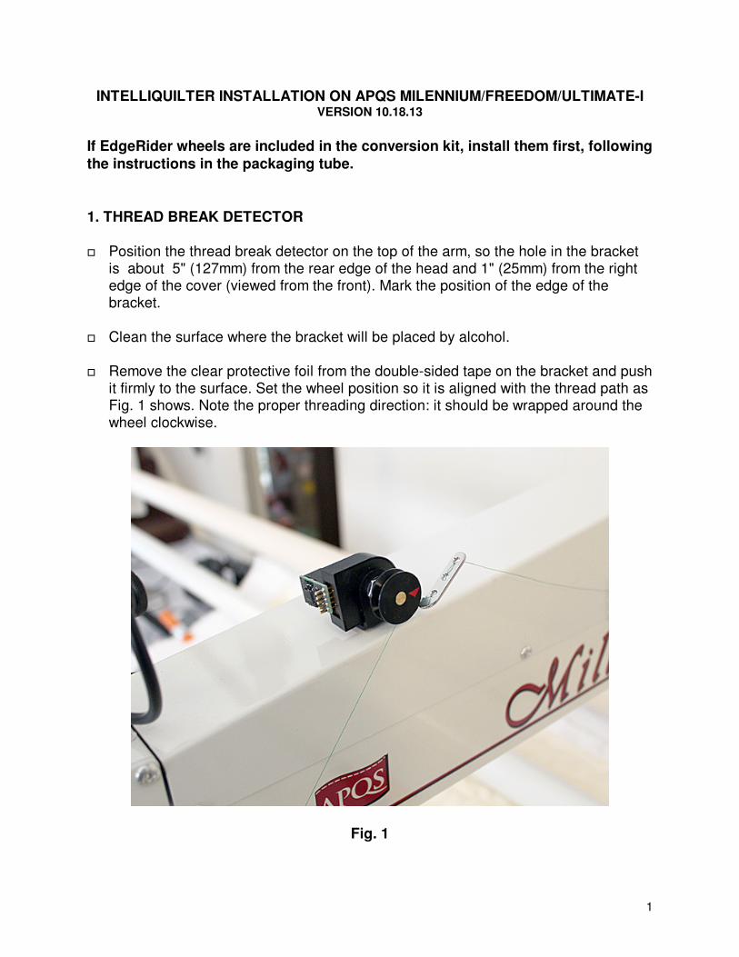
2. COMPUTER BRACKET
� Remove the tablet from the docking station.
� Remove the yellow thumbscrews, the other screws and the double nuts from the
docking station.
� Mount the docking station on the computer bracket as Fig. 2 shows.
Fig. 2
3
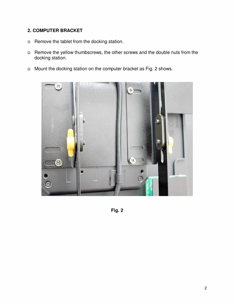
� Mount the computer bracket, with the docking station facing the front, using the four supplied 5/8” long #8-32 Phillips screws on both sides on the front of the head of the machine.
� Move the docking station up/down and adjust its tilt to the operator’s preference.
Fig. 3
4
3. Y-MOTOR
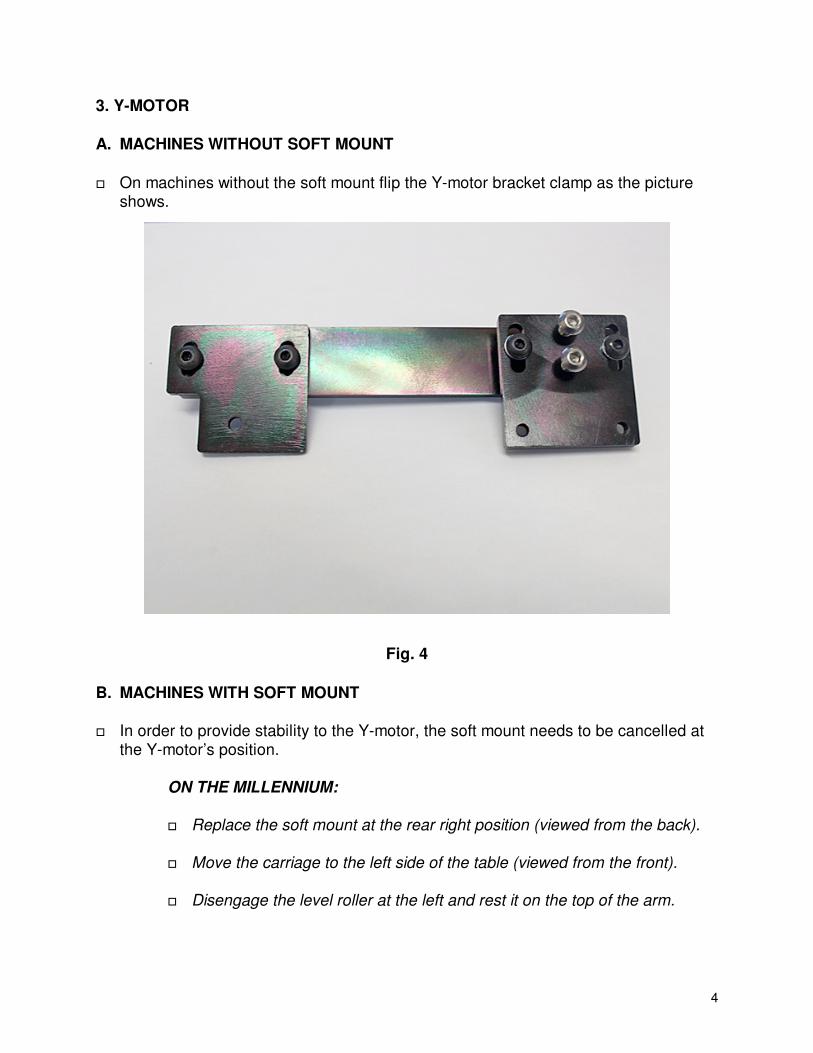
A. MACHINES WITHOUT SOFT MOUNT
� On machines without the soft mount flip the Y-motor bracket clamp as the picture shows.
Fig. 4
B. MACHINES WITH SOFT MOUNT
� In order to provide stability to the Y-motor, the soft mount needs to be cancelled at
the Y-motor’s position.
ON THE MILLENNIUM: � Replace the soft mount at the rear right position (viewed from the back).
� Move the carriage to the left side of the table (viewed from the front).
� Disengage the level roller at the left and rest it on the top of the arm.

5
Fig. 5
� Pull the arm toward the back of the carriage, so you can reach the rear wheel axle. Prop up the arm at that position.
6
Fig. 6
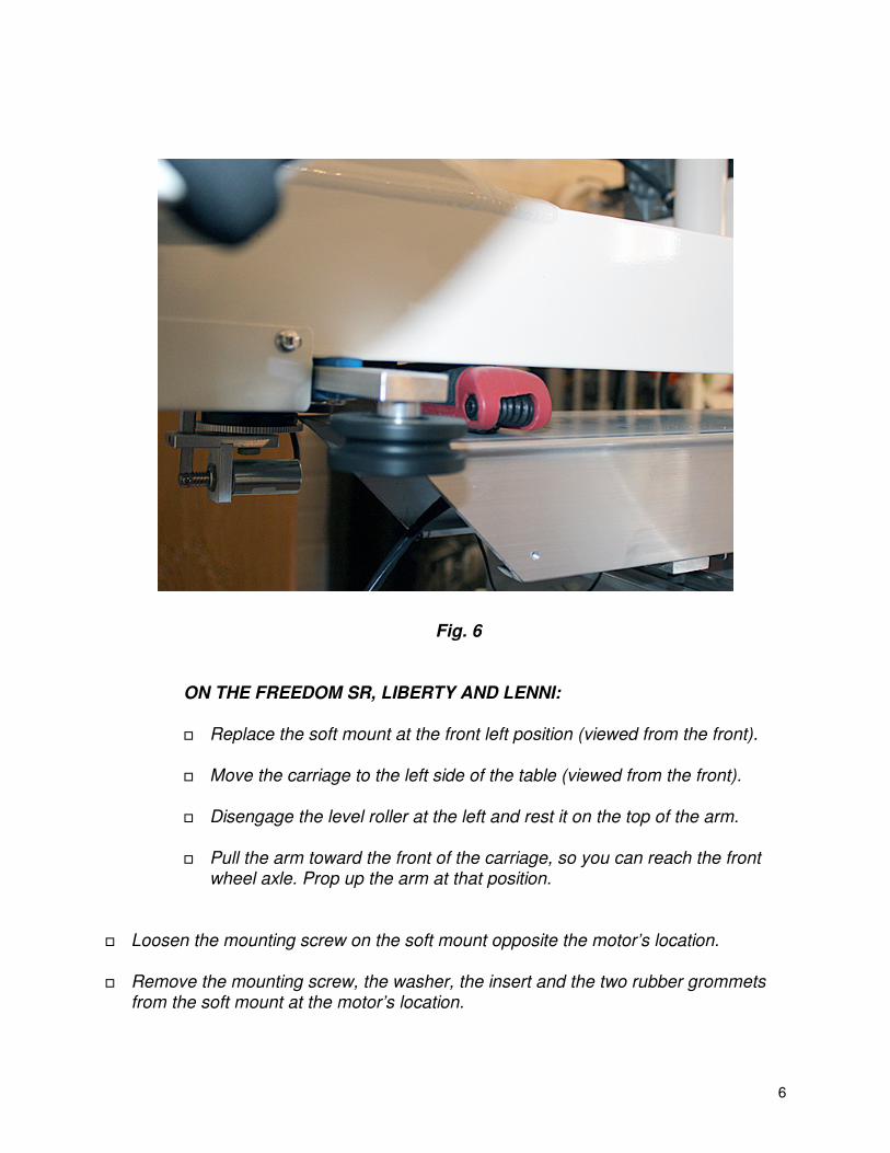
ON THE FREEDOM SR, LIBERTY AND LENNI: � Replace the soft mount at the front left position (viewed from the front). � Move the carriage to the left side of the table (viewed from the front).
� Disengage the level roller at the left and rest it on the top of the arm.
� Pull the arm toward the front of the carriage, so you can reach the front
wheel axle. Prop up the arm at that position.
� Loosen the mounting screw on the soft mount opposite the motor’s location.
� Remove the mounting screw, the washer, the insert and the two rubber grommets
from the soft mount at the motor’s location.
7
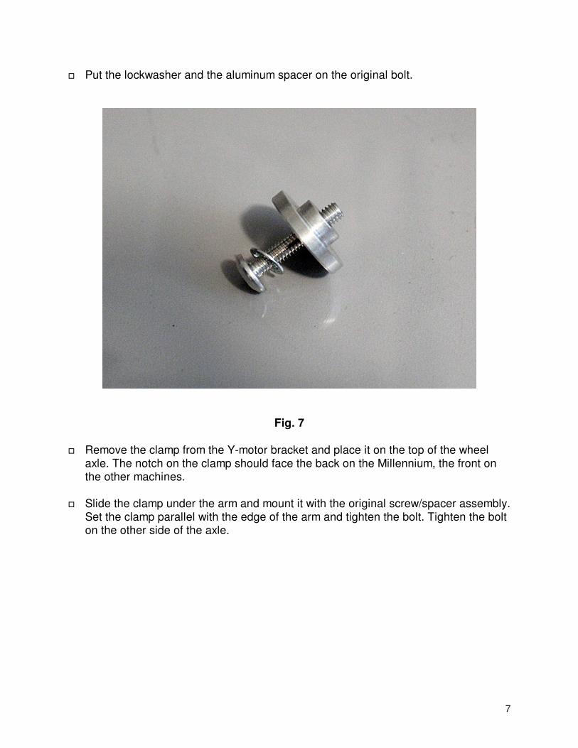
� Put the lockwasher and the aluminum spacer on the original bolt.
Fig. 7
� Remove the clamp from the Y-motor bracket and place it on the top of the wheel axle. The notch on the clamp should face the back on the Millennium, the front on the other machines.
� Slide the clamp under the arm and mount it with the original screw/spacer assembly.
Set the clamp parallel with the edge of the arm and tighten the bolt. Tighten the bolt on the other side of the axle.

8
Fig. 8
� Push the wheels back on the carriage and remount the level roller.
� Remove the plastic cover from the motor. Push all the connectors down, for they
may have loosened during shipping.
9
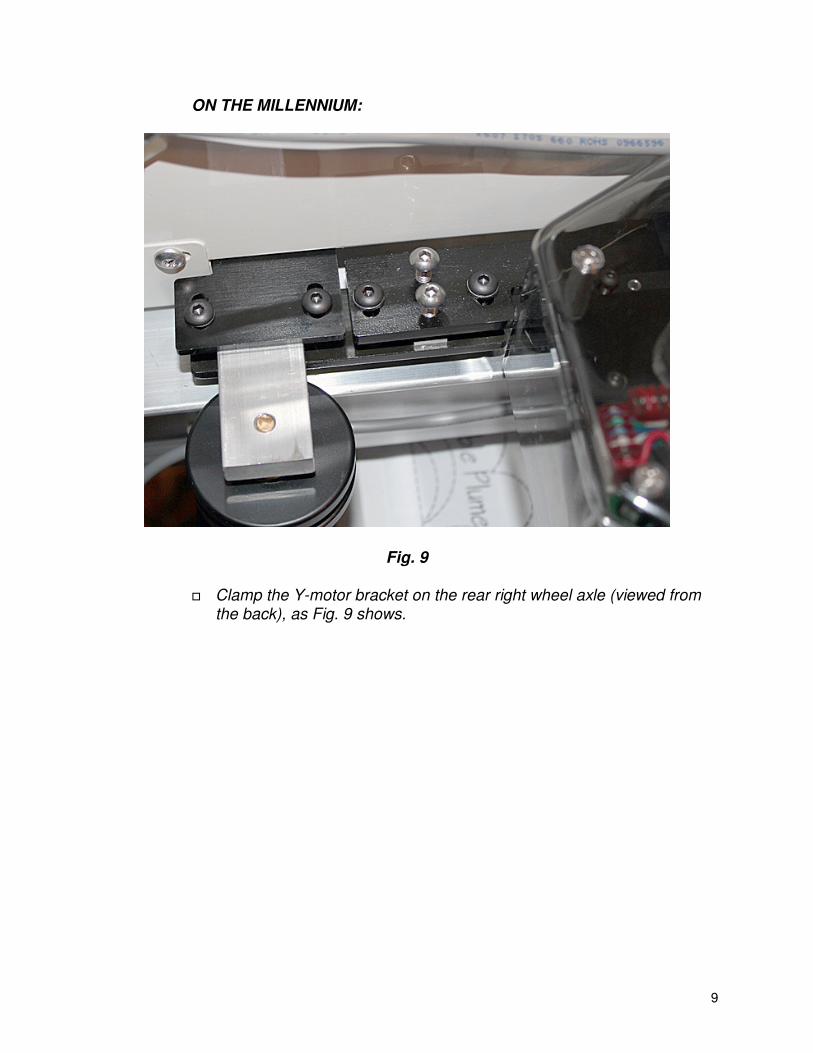
ON THE MILLENNIUM:
Fig. 9
� Clamp the Y-motor bracket on the rear right wheel axle (viewed from the back), as Fig. 9 shows.
10
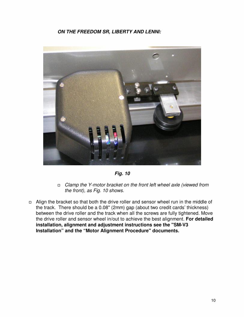
ON THE FREEDOM SR, LIBERTY AND LENNI:
Fig. 10 � Clamp the Y-motor bracket on the front left wheel axle (viewed from
the front), as Fig. 10 shows.
� Align the bracket so that both the drive roller and sensor wheel run in the middle of the track. There should be a 0.08" (2mm) gap (about two credit cards’ thickness) between the drive roller and the track when all the screws are fully tightened. Move
the drive roller and sensor wheel in/out to achieve the best alignment. For detailed
installation, alignment and adjustment instructions see the "SM-V3
Installation” and the “Motor Alignment Procedure" documents.
11
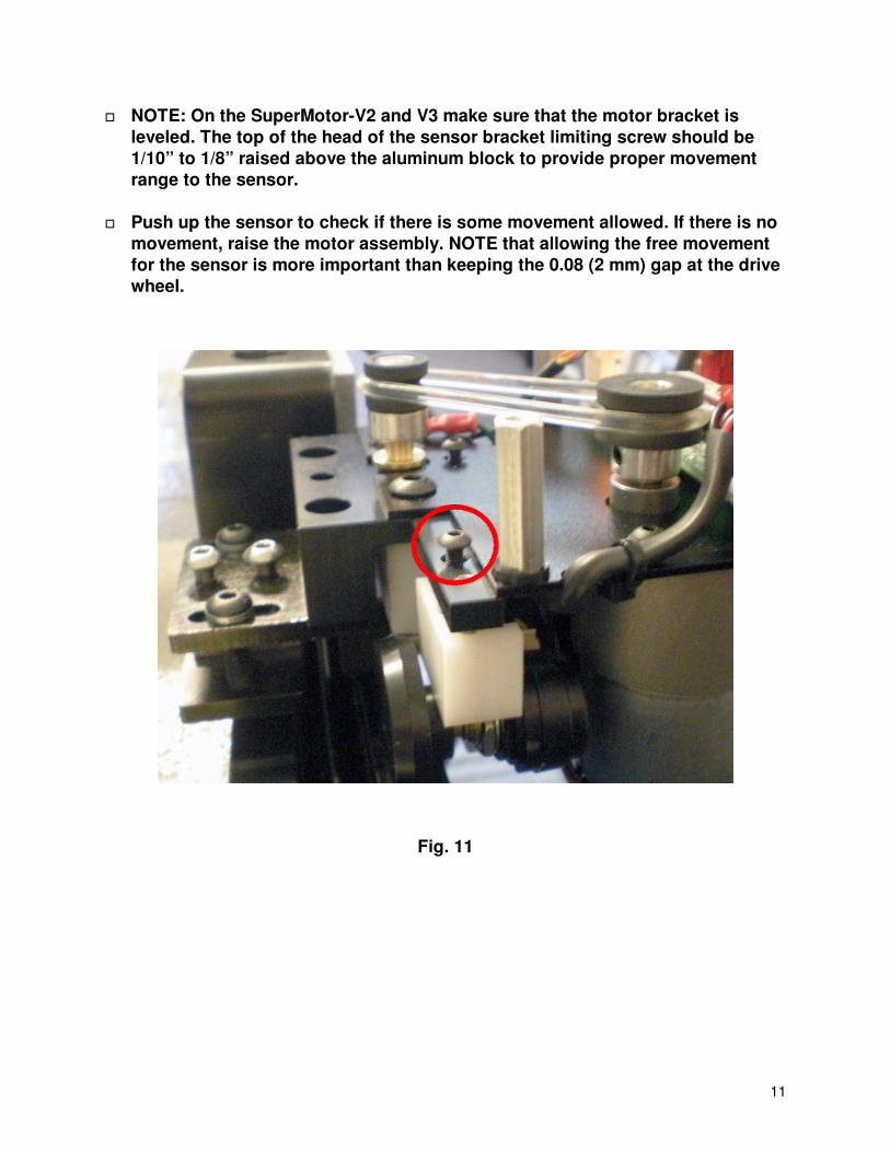
� NOTE: On the SuperMotor-V2 and V3 make sure that the motor bracket is
leveled. The top of the head of the sensor bracket limiting screw should be
1/10” to 1/8” raised above the aluminum block to provide proper movement
range to the sensor.
� Push up the sensor to check if there is some movement allowed. If there is no
movement, raise the motor assembly. NOTE that allowing the free movement
for the sensor is more important than keeping the 0.08 (2 mm) gap at the drive
wheel.
Fig. 11
12
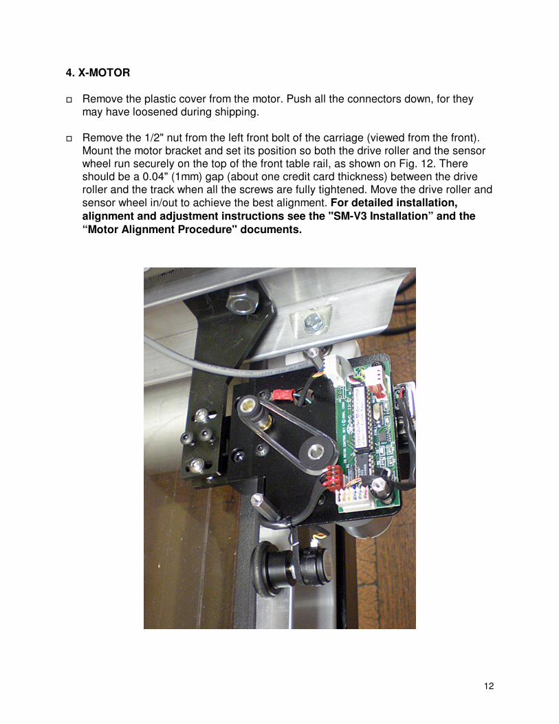
4. X-MOTOR
� Remove the plastic cover from the motor. Push all the connectors down, for they
may have loosened during shipping. � Remove the 1/2" nut from the left front bolt of the carriage (viewed from the front).
Mount the motor bracket and set its position so both the drive roller and the sensor wheel run securely on the top of the front table rail, as shown on Fig. 12. There should be a 0.04" (1mm) gap (about one credit card thickness) between the drive roller and the track when all the screws are fully tightened. Move the drive roller and
sensor wheel in/out to achieve the best alignment. For detailed installation,
alignment and adjustment instructions see the "SM-V3 Installation” and the
“Motor Alignment Procedure" documents.
13
Fig. 12
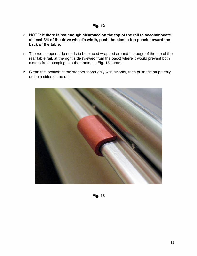
� NOTE: If there is not enough clearance on the top of the rail to accommodate
at least 3/4 of the drive wheel's width, push the plastic top panels toward the
back of the table.
� The red stopper strip needs to be placed wrapped around the edge of the top of the
rear table rail, at the right side (viewed from the back) where it would prevent both motors from bumping into the frame, as Fig. 13 shows.
� Clean the location of the stopper thoroughly with alcohol, then push the strip firmly
on both sides of the rail.
Fig. 13
14
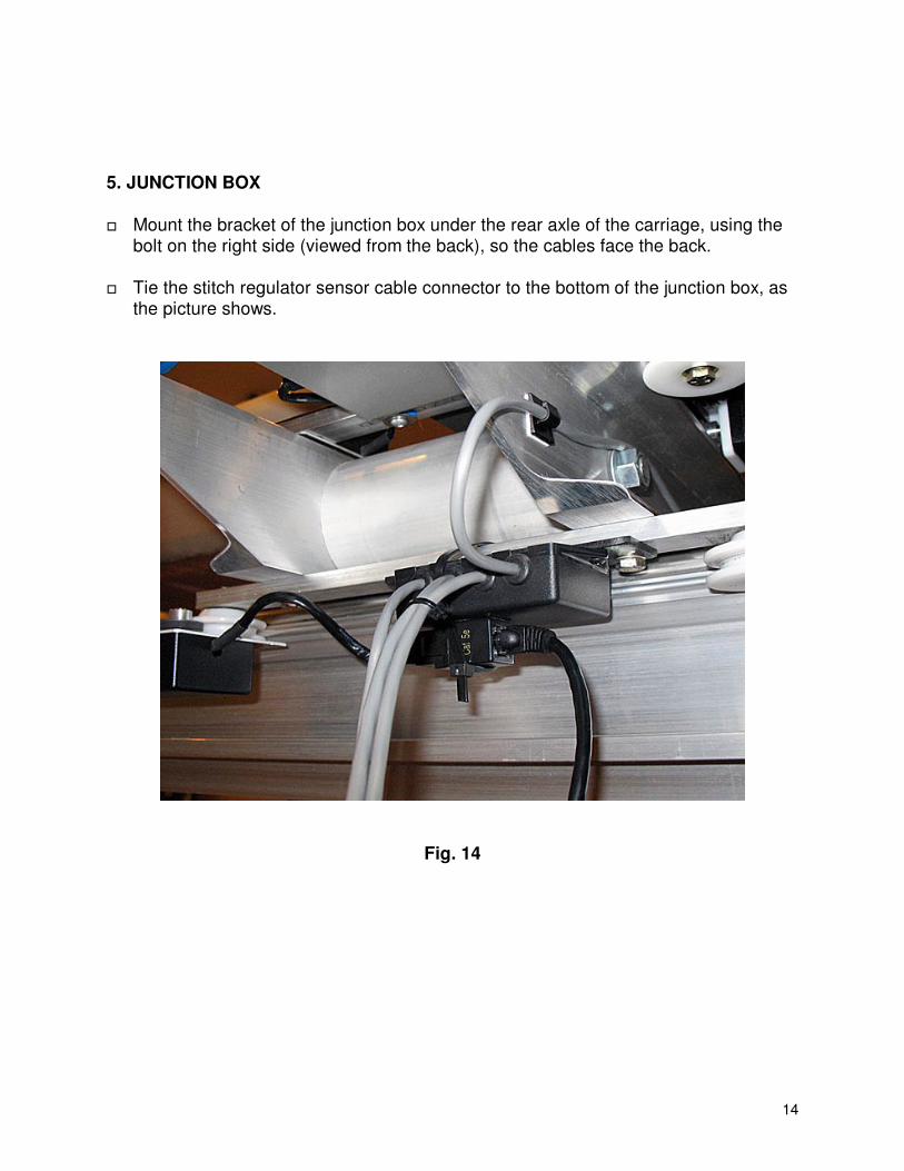
5. JUNCTION BOX
� Mount the bracket of the junction box under the rear axle of the carriage, using the
bolt on the right side (viewed from the back), so the cables face the back.
� Tie the stitch regulator sensor cable connector to the bottom of the junction box, as the picture shows.
Fig. 14
15
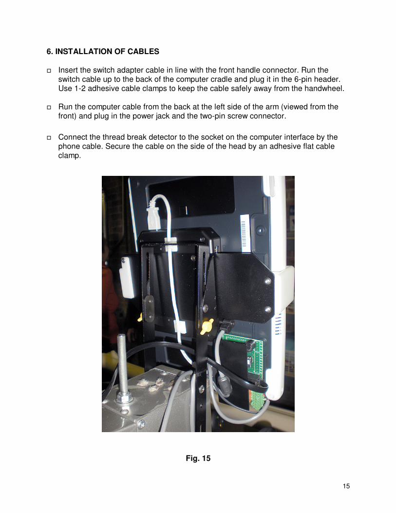
6. INSTALLATION OF CABLES
� Insert the switch adapter cable in line with the front handle connector. Run the
switch cable up to the back of the computer cradle and plug it in the 6-pin header. Use 1-2 adhesive cable clamps to keep the cable safely away from the handwheel.
� Run the computer cable from the back at the left side of the arm (viewed from the
front) and plug in the power jack and the two-pin screw connector.
� Connect the thread break detector to the socket on the computer interface by the
phone cable. Secure the cable on the side of the head by an adhesive flat cable clamp.
Fig. 15
16
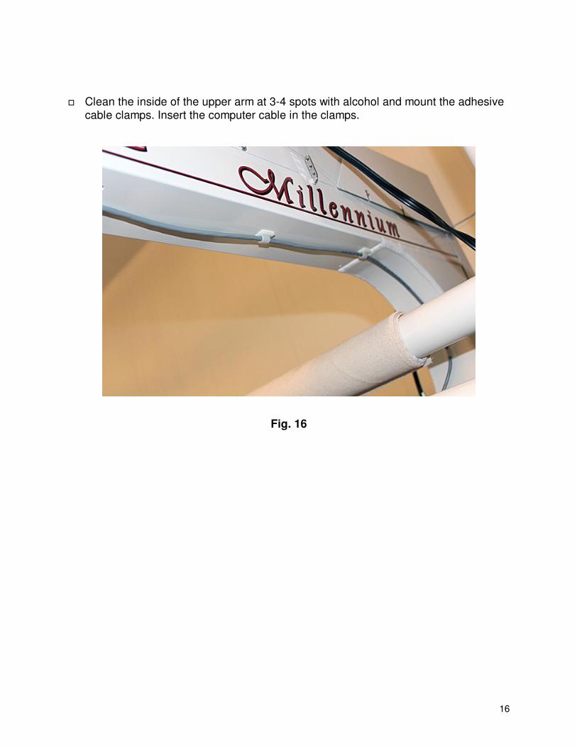
� Clean the inside of the upper arm at 3-4 spots with alcohol and mount the adhesive
cable clamps. Insert the computer cable in the clamps.
Fig. 16
17
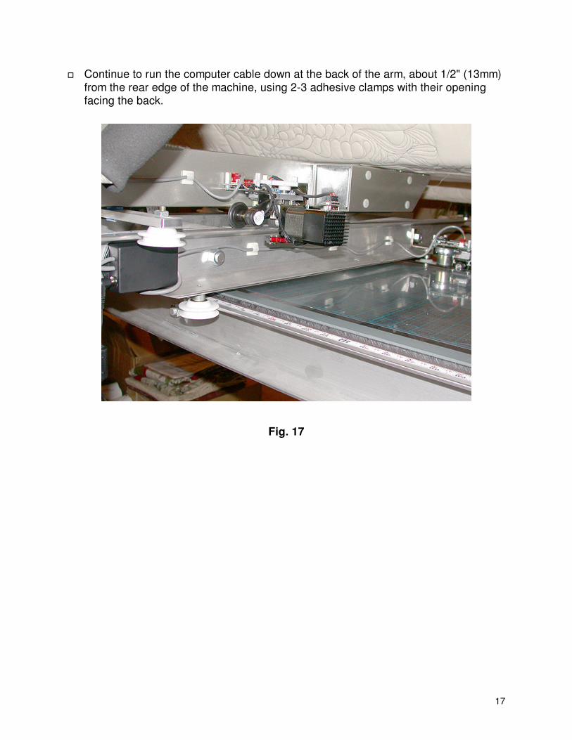
� Continue to run the computer cable down at the back of the arm, about 1/2" (13mm) from the rear edge of the machine, using 2-3 adhesive clamps with their opening facing the back.
Fig. 17

18
� Run the Y-motor cable from the back on the side of the lower arm, using 2-3 adhesive clamps with their opening facing up, as shown on Fig. 10. Plug in the connector. Tie the cable to the post as Fig. 18 shows.
Fig. 18
19
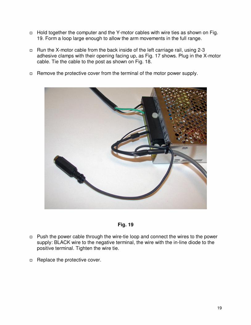
� Hold together the computer and the Y-motor cables with wire ties as shown on Fig. 19. Form a loop large enough to allow the arm movements in the full range.
� Run the X-motor cable from the back inside of the left carriage rail, using 2-3
adhesive clamps with their opening facing up, as Fig. 17 shows. Plug in the X-motor cable. Tie the cable to the post as shown on Fig. 18.
� Remove the protective cover from the terminal of the motor power supply.
Fig. 19
� Push the power cable through the wire-tie loop and connect the wires to the power supply: BLACK wire to the negative terminal, the wire with the in-line diode to the positive terminal. Tighten the wire tie.
� Replace the protective cover.
20
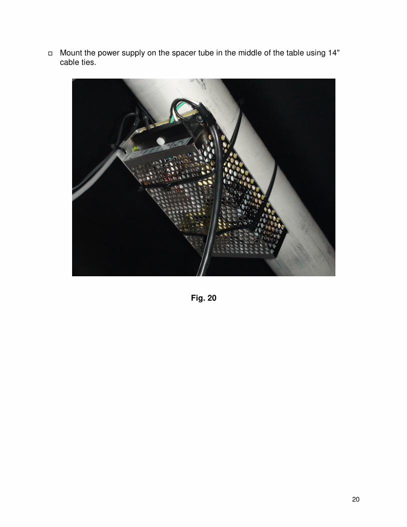
� Mount the power supply on the spacer tube in the middle of the table using 14" cable ties.
Fig. 20
21
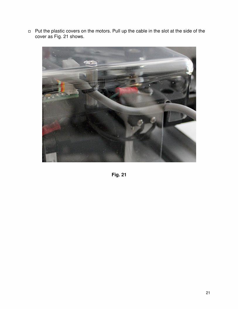
� Put the plastic covers on the motors. Pull up the cable in the slot at the side of the cover as Fig. 21 shows.
Fig. 21
22
� Snap on the computer and adjust the height and angle of the computer docking station. Tighten the four screws at that position.
� Turn on the computer. When the booting completes, the motors will be engaged
with the tracks. Select and quit Manual Mode repeatedly to see if the motors are sufficiently disengaged all along the tracks and make the necessary height adjustments. Make sure that the gap between the rollers and the tracks is not more than 0.04" (1mm). Try to set the gap to the minimum safe distance, so there is no intermittent drag along the tracks.
� Go to Utilities->Preferences.
� Set the motor engagement strength for each motor separately. Start with a lower
number, then increase the number and test the resistance of the motor in each direction, until there is definite resistance everywhere.
� The optimal settings range is 8...14 on the standard motors, 3…6 on the
SuperMotors. You need to raise the motor if the final setting is below the lower limit, lower it if the setting is above the upper limit.
� Go to Utilities->Measure/Calibrate and calibrate the sensor wheels following the
on-screen instructions.
� Go to System->Interface Setup/Test. � Enter all the settings shown on the screenshot that was taped to the top of the box
containing the tablet and the docking station.
� Test the single stitch and start switches, and the thread break detector. Note that the detector works only when the machine is stitching (the Start Switch label is red). If the needle positioner is slow on the machine, increase the delays before and after the single stitch.
� Set the local date and time. Enter at least eight digits: two digits for the month, two
digits for the day, two digits for hours (in 24-hour format) and two digits for minutes. Continue with another four digits for the year only if the display does not show the proper year.
� Show the brightness control to the customer and set the desired level (1…7).
� COPY THE LOGS AND POST THE logs.tar.gz FILE TO THE SUPPORT PAGE
OF www.intelliquilter.com.