Embed Size (px)
Citation preview

IntelliPro™
4x160 and 4x100Four Speed Variable
Centrifugal Pump with Integral Trap
IMPORTANT SAFETY INSTRUCTIONSREAD AND FOLLOW ALL INSTRUCTIONSSAVE THESE INSTRUCTIONS

© 2006 Pentair Water Pool and Spa, Inc. All rights reserved
This document is subject to change without notice
1620 Hawkins Ave., Sanford, NC 27330 • (919) 566-800010951 West Los Angeles Ave., Moorpark, CA 93021 • (805) 553-5000
Sta-Rite, IntelliTouch, EasyTouch, IntelliPro and the Pentair Water Pool and Spa logo are trademarks of PentairWater Pool and Spa, Inc. Other trademarks and trade names may be used in this document to refer to either theentities claiming the marks and names or their products. Pentair Water Pool and Spa, Inc. disclaims proprietaryinterest in marks and names of others.
P/N 357291 Rev A - 10/18/06
Technical Support
Sanford, North Carolina (8 A.M. to 5 P.M.)
Phone: (800) 831-7133
Moorpark, California (8 A.M. to 5 P.M.)
Phone: (800) 831-7133
Fax: (800) 284-4151
Web sites: visit www.pentairpool.com and staritepool.com
i
IntelliPro Installation and User’s Guide
Contents
Important Safety Precautions .............................................................................. iii
Section 1: Overview .............................................................................................. 1
IntelliPro Variable Speed Pump ............................................................................... 1IntelliPro models ...................................................................................................... 1External Control ....................................................................................................... 1Features .................................................................................................................. 2IntelliPro Motor Assembly........................................................................................ 2
Drive assembly and electronics enclosure ................................................. 2Motor fan cover ........................................................................................... 2Motor assembly ........................................................................................... 2Operator Control Panel ................................................................................ 2
Communication Port for communication to IntelliTouch,or IntelliComm via the two-wire RS-485 cable......................................................... 2IntelliPro Drive Assembly and Control Panel ........................................................... 3IntelliPro Motor Features ......................................................................................... 3IntelliPro Operator Control Panel ............................................................................. 4
Controls and LEDs ...................................................................................... 4
Section 2: Installation ........................................................................................... 5
Before installation .................................................................................................... 5Teflon Taping Instructions ............................................................................ 5Piping ........................................................................................................... 6Fittings ......................................................................................................... 6
Wiring the IntelliPro .................................................................................................. 7External Control with IntelliComm Communication Center ...................................... 8Connecting IntelliPro 4 to an EasyTouch System ................................................... 9Connecting IntelliPro 4 to an IntelliTouch System.................................................... 12
Section 3: Operation ............................................................................................. 15
Setting the pump preset speed ................................................................................ 15Adjusting the pump speed ........................................................................... 16Starting the pump ........................................................................................ 16Stopping the pump ....................................................................................... 16
Setting the pump communication address .............................................................. 16Resetting the pump to factory defaults .................................................................... 17Priming the pump for the first time or after service .................................................. 18
Priming the Pump ........................................................................................ 19Storage/Winterizing: ................................................................................................ 20Draining Pump ......................................................................................................... 20Startup For Winterized Equipment........................................................................... 21Pump Service .......................................................................................................... 21
ii
IntelliPro Installation and User’s Guide
Section 4: User Maintenance ................................................................................ 23
Pump Strainer Basket ............................................................................................. 23Pump Strainer Basket Service ................................................................................ 23Motor Service .......................................................................................................... 24
Winterizing ................................................................................................... 25Priming the pump after service ................................................................................ 25Pump Disassembly ................................................................................................. 27
Section 5: Removal and Replacement ................................................................. 27
Drive Assembly Removal and Installation ............................................................... 27Pump Disassembly/Removing Old Seal ................................................................. 29Pump Reassembly/Installing New Seal .................................................................. 30Illustrated Parts List ................................................................................................. 31IntelliPro Flow and Power vs Flow Pump Curve ..................................................... 32IntelliPro Electrical Specifications ........................................................................... 32IntelliPro Pump Dimensions .................................................................................... 32
Section 6: Troubleshooting .................................................................................. 33
Warning and Alarm conditions ................................................................................. 33Alarm and warning LED sequence .......................................................................... 33General IntelliPro Troubleshooting Problems ........................................................... 34
Contents (Continued)

iii
IntelliPro Installation and User’s Guide
Important Notice:
Attention Installer: This manual contains important information about the installation, operation and safe useof this product. This information should be given to the owner and/or operator of this equipment.
WARNING — Before installing this product, read and follow all warning notices and instructions whichare included. Failure to follow safety warnings and instructions can result in severe injury,death, or property damage. Call (800) 831-7133 for additional free copies of theseinstructions.
WARNING — Entrapment Avoidance Notice:
The suction outlet connected to a swimming pool or spa pump can pull a high vacuumif it is blocked. Therefore, if only one suction outlet smaller than 18" x 23" is used,anyone blocking the suction outlet with their body can be trapped and held against thesuction outlet. Disembowelment or drowning can result. Therefore, if small suctionoutlets are used with this pump, to prevent this entrapment and possible death, installat least two suction outlets in the body of water. Separate these suction outlets asdescribed in the International Residential Code (IRC), the International Business Code(IBC), the Consumer Products Safety Council (CPSC) Guidelines for Entrapment Hazards:Making Pools and Spas Safer or ANSI/IAF-7 Standard for Suction Entrapment Avoidancein Swimming Pools, Wading Pools, Spas, Hot Tubs and Catch Basins. If suction outletsare not used, additional entrapment avoidance measures as described in the CPSCGuidelines or ANSI/IAF-7 should be employed.
The covers used on suction outlets should be approved and listed as conforming to thecurrently published edition of ANSI/ASME A112.19.8 Standard covering Suction Fittingsfor Use in Swimming Pools, Wading Pools, Spas and Hot Tubs. These covers should beinspected regularly and replaced if cracked, broken or older than the design lifetimeindicated on them by the manufacturer. The maximum possible flow rate of this pumpshould be less than or equal to the maximum approved flow rate indicated on the suctionoutlet cover by the manufacturer. THE USE OF UNAPPROVED COVERS OR ALLOWINGUSE OF THE POOL OR SPA WHEN COVERS ARE CRACKED OR BROKEN CANRESULT IN HAIR ENTANGLEMENT WHICH CAN RESULT IN DEATH.
WARNING — Risk of electrical shock or electrocution.
This pool pump must be installed by a licensed or certified electrician or a qualified poolserviceman in accordance with the National Electrical Code and all applicable local codesand ordinances. Improper installation will create an electrical hazard which could result indeath or serious injury to pool users, installers, or others due to electrical shock, and mayalso cause damage to property.
Always disconnect power to the pool pump at the circuit breaker before servicing thepump. Failure to do so could result in death or serious injury to serviceman, pool usersor others due to electric shock.
IMPORTANT SAFETY PRECAUTIONS
iv
IntelliPro Installation and User’s Guide
IMPORTANT SAFETY PRECAUTIONS (continued)
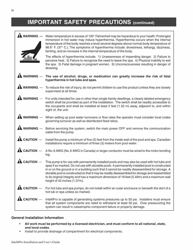
WARNING — Water temperature in excess of 100° Fahrenheit may be hazardous to your health. Prolongedimmersion in hot water may induce hyperthermia. Hyperthermia occurs when the internaltemperature of the body reaches a level several degrees above normal body temperature of98.6° F. (37° C.). The symptoms of hyperthermia include: drowsiness, lethargy, dizziness,fainting, and an increase in the internal temperature of the body.
The effects of hyperthermia include: 1) Unawareness of impending danger. 2) Failure toperceive heat. 3) Failure to recognize the need to leave the spa. 4) Physical inability to exitthe spa. 5) Fetal damage in pregnant women. 6) Unconsciousness resulting in danger ofdrowning.
WARNING — The use of alcohol, drugs, or medication can greatly increase the risk of fatalhyperthermia in hot tubs and spas.
WARNING — To reduce the risk of injury, do not permit children to use this product unless they are closelysupervised at all times.
WARNING — For units intended for use in other than single-family dwellings, a clearly labeled emergencyswitch shall be provided as part of the installation. The switch shall be readily accessible tothe occupants and shall be installed at least 5 feet (1.52 m) away, adjacent to, and withinsight of, the unit.
WARNING — When setting up pool water turnovers or flow rates the operator must consider local codesgoverning turnover as well as disinfectant feed ratios.
WARNING — Before servicing the system, switch the main power OFF and remove the communicationcable from the pump.
CAUTION — Install the pump a minimum of five (5) feet from the inside wall of the pool and spa. Canadianinstallations require a minimum of three (3) meters from pool water.
CAUTION — A No. 8 AWG (No. 6 AWG in Canada) or larger conductor must be wired to the motor bondinglug.
CAUTION — This pump is for use with permanently installed pools and may also be used with hot tubs andspas if so marked. Do not use with storable pools. A permanently installed pool is constructedin or on the ground or in a building such that it cannot be readily disassembled for storage. Astorable pool is constructed so that it may be readily disassembled for storage and reassembledto its original integrity and has a maximum dimension of 18 feet (5.49m) and a maximum wallheight of 42 inches (1.07m).
CAUTION — For hot tubs and spa pumps, do not install within an outer enclosure or beneath the skirt of ahot tub or spa unless so marked.
CAUTION — IntelliPro is capable of generating systems pressures up to 50 psi. Installers must ensurethat all system components are rated to withstand at least 50 psi. Over pressurizing thesystem can result in catastrophic component failure or property damage.
General Installation Information
• All work must be performed by a licensed electrician, and must conform to all national, state,and local codes.
• Install to provide drainage of compartment for electrical components.
v
IntelliPro Installation and User’s Guide
General Installation Information
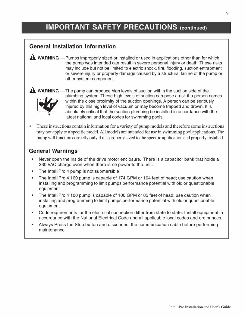
WARNING —Pumps improperly sized or installed or used in applications other than for whichthe pump was intended can result in severe personal injury or death. These risksmay include but not be limited to electric shock, fire, flooding, suction entrapmentor severe injury or property damage caused by a structural failure of the pump orother system component.
WARNING —The pump can produce high levels of suction within the suction side of theplumbing system. These high levels of suction can pose a risk if a person comeswithin the close proximity of the suction openings. A person can be seriouslyinjured by this high level of vacuum or may become trapped and drown. It isabsolutely critical that the suction plumbing be installed in accordance with thelatest national and local codes for swimming pools.
• These instructions contain information for a variety of pump models and therefore some instructionsmay not apply to a specific model. All models are intended for use in swimming pool applications. Thepump will function correctly only if it is properly sized to the specific application and properly installed.
IMPORTANT SAFETY PRECAUTIONS (continued)
General Warnings• Never open the inside of the drive motor enclosure. There is a capacitor bank that holds a
230 VAC charge even when there is no power to the unit.
• The IntelliPro 4 pump is not submersible
• The IntelliPro 4 160 pump is capable of 174 GPM or 104 feet of head; use caution wheninstalling and programming to limit pumps performance potential with old or questionableequipment
• The IntelliPro 4 100 pump is capable of 100 GPM or 85 feet of head; use caution wheninstalling and programming to limit pumps performance potential with old or questionableequipment
• Code requirements for the electrical connection differ from state to state. Install equipment inaccordance with the National Electrical Code and all applicable local codes and ordinances.
• Always Press the Stop button and disconnect the communication cable before performingmaintenance

vi
IntelliPro Installation and User’s Guide
Blank Page
1
IntelliPro Installation and User’s Guide
Section 1Overview
IntelliPro Variable Speed Pump
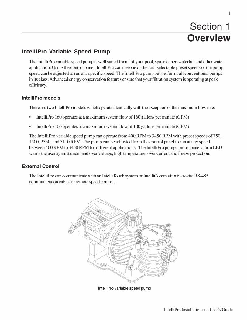
The IntelliPro variable speed pump is well suited for all of your pool, spa, cleaner, waterfall and other waterapplication. Using the control panel, IntelliPro can use one of the four selectable preset speeds or the pumpspeed can be adjusted to run at a specific speed. The IntelliPro pump out performs all conventional pumpsin its class. Advanced energy conservation features ensure that your filtration system is operating at peakefficiency.
IntelliPro models
There are two IntelliPro models which operate identically with the exception of the maximum flow rate:
• IntelliPro 160 operates at a maximum system flow of 160 gallons per minute (GPM)
• IntelliPro 100 operates at a maximum system flow of 100 gallons per minute (GPM)
The IntelliPro variable speed pump can operate from 400 RPM to 3450 RPM with preset speeds of 750,1500, 2350, and 3110 RPM. The pump can be adjusted from the control panel to run at any speedbetween 400 RPM to 3450 RPM for different applications. The IntelliPro pump control panel alarm LEDwarns the user against under and over voltage, high temperature, over current and freeze protection.
External Control
The IntelliPro can communicate with an IntelliTouch system or IntelliComm via a two-wire RS-485communication cable for remote speed control.
IntelliPro variable speed pump
2
IntelliPro Installation and User’s Guide
Features
• Adjusts to various pool sizes• Prevents thermal overload• Detects and prevents damage from under and over voltage conditions• Protects against freezing• Communicates with the Pentair IntelliTouch system via a two-wire cable connection• Easy to use operator control panel• Operator control panel buttons for speed control• Built-in strainer pot and volute• Ultra energy-efficient TEFC Square Flange Motor• Compatibility with most cleaning systems, filters, and jet action spas• Driver assembly features permanent magnet synchronous motor• Heavy-duty, durable construction designed for long life• UL approval
IntelliPro Motor Assembly
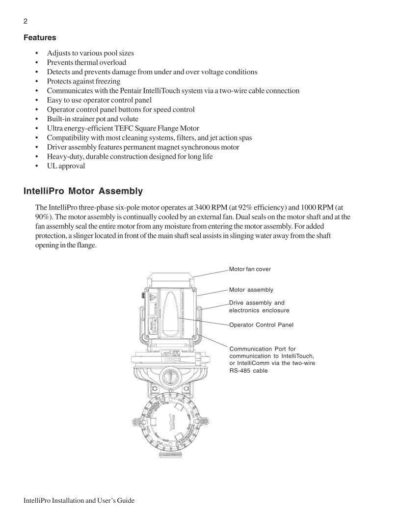
The IntelliPro three-phase six-pole motor operates at 3400 RPM (at 92% efficiency) and 1000 RPM (at90%). The motor assembly is continually cooled by an external fan. Dual seals on the motor shaft and at thefan assembly seal the entire motor from any moisture from entering the motor assembly. For addedprotection, a slinger located in front of the main shaft seal assists in slinging water away from the shaftopening in the flange.
Drive assembly andelectronics enclosure
Motor fan cover
Communication Port forcommunication to IntelliTouch,or IntelliComm via the two-wireRS-485 cable
Motor assembly
Operator Control Panel
3
IntelliPro Installation and User’s Guide
IntelliPro Drive Assembly and Control Panel
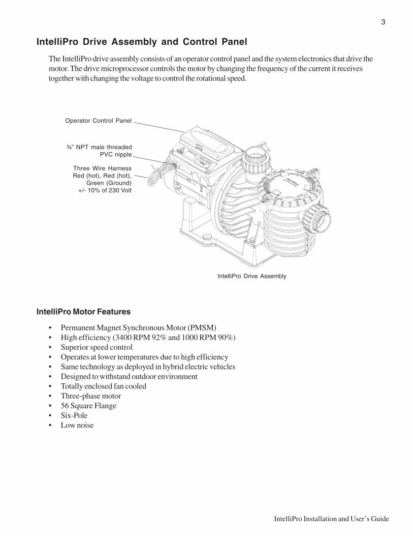
The IntelliPro drive assembly consists of an operator control panel and the system electronics that drive themotor. The drive microprocessor controls the motor by changing the frequency of the current it receivestogether with changing the voltage to control the rotational speed.
IntelliPro Motor Features
• Permanent Magnet Synchronous Motor (PMSM)• High efficiency (3400 RPM 92% and 1000 RPM 90%)• Superior speed control• Operates at lower temperatures due to high efficiency• Same technology as deployed in hybrid electric vehicles• Designed to withstand outdoor environment• Totally enclosed fan cooled• Three-phase motor• 56 Square Flange• Six-Pole• Low noise
Three Wire HarnessRed (hot), Red (hot),
Green (Ground)+/- 10% of 230 Volt
¾” NPT male threadedPVC nipple
Operator Control Panel
IntelliPro Drive Assembly
4
IntelliPro Installation and User’s Guide
Controls and LEDs
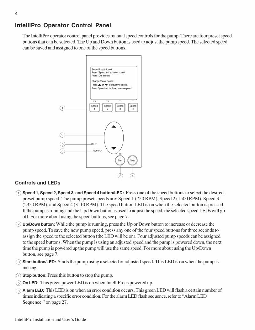
Speed 1, Speed 2, Speed 3, and Speed 4 button/LED: Press one of the speed buttons to select the desiredpreset pump speed. The pump preset speeds are: Speed 1 (750 RPM), Speed 2 (1500 RPM), Speed 3(2350 RPM), and Speed 4 (3110 RPM). The speed button LED is on when the selected button is pressed.If the pump is running and the Up/Down button is used to adjust the speed, the selected speed LEDs will gooff. For more about using the speed buttons, see page 7.
Up/Down button: While the pump is running, press the Up or Down button to increase or decrease thepump speed. To save the new pump speed, press any one of the four speed buttons for three seconds toassign the speed to the selected button (the LED will be on). Four adjusted pump speeds can be assignedto the speed buttons. When the pump is using an adjusted speed and the pump is powered down, the nexttime the pump is powered up the pump will use the same speed. For more about using the Up/Downbutton, see page 7.
Start button/LED: Starts the pump using a selected or adjusted speed. This LED is on when the pump isrunning.
Stop button: Press this button to stop the pump.
On LED: This green power LED is on when IntelliPro is powered up.
Alarm LED: This LED is on when an error condition occurs. This green LED will flash a certain number oftimes indicating a specific error condition. For the alarm LED flash sequence, refer to “Alarm LEDSequence,” on page 27.
3
4
5
6
IntelliPro Operator Control Panel
The IntelliPro operator control panel provides manual speed controls for the pump. There are four preset speedbuttons that can be selected. The Up and Down button is used to adjust the pump speed. The selected speedcan be saved and assigned to one of the speed buttons.
1
2
1
2
3 4
5
6
5
IntelliPro Installation and User’s Guide
Section 2Installation
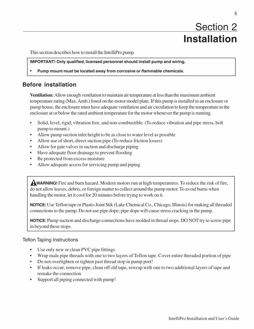
This section describes how to install the IntelliPro pump.
IMPORTANT! Only qualified, licensed personnel should install pump and wiring.
• Pump mount must be located away from corrosive or flammable chemicals.
Before installation
Ventilation: Allow enough ventilation to maintain air temperature at less than the maximum ambienttemperature rating (Max. Amb.) listed on the motor model plate. If this pump is installed in an enclosure orpump house, the enclosure must have adequate ventilation and air circulation to keep the temperature in theenclosure at or below the rated ambient temperature for the motor whenever the pump is running.
• Solid, level, rigid, vibration free, and non-combustible. (To reduce vibration and pipe stress, boltpump to mount.)
• Allow pump suction inlet height to be as close to water level as possible• Allow use of short, direct suction pipe (To reduce friction losses)• Allow for gate valves in suction and discharge piping• Have adequate floor drainage to prevent flooding• Be protected from excess moisture• Allow adequate access for servicing pump and piping
WARNING! Fire and burn hazard. Modern motors run at high temperatures. To reduce the risk of fire,do not allow leaves, debris, or foreign matter to collect around the pump motor. To avoid burns whenhandling the motor, let it cool for 20 minutes before trying to work on it.
NOTICE: Use Teflon tape or Plasto-Joint Stik (Lake Chemical Co., Chicago, Illinois) for making all threadedconnections to the pump. Do not use pipe dope; pipe dope will cause stress cracking in the pump.
NOTICE: Pump suction and discharge connections have molded in thread stops. DO NOT try to screw pipein beyond these stops.
Teflon Taping Instructions
• Use only new or clean PVC pipe fittings• Wrap male pipe threads with one to two layers of Teflon tape. Cover entire threaded portion of pipe• Do not overtighten or tighten past thread stop in pump port!• If leaks occur, remove pipe, clean off old tape, rewrap with one to two additional layers of tape and
remake the connection• Support all piping connected with pump!
6
IntelliPro Installation and User’s Guide
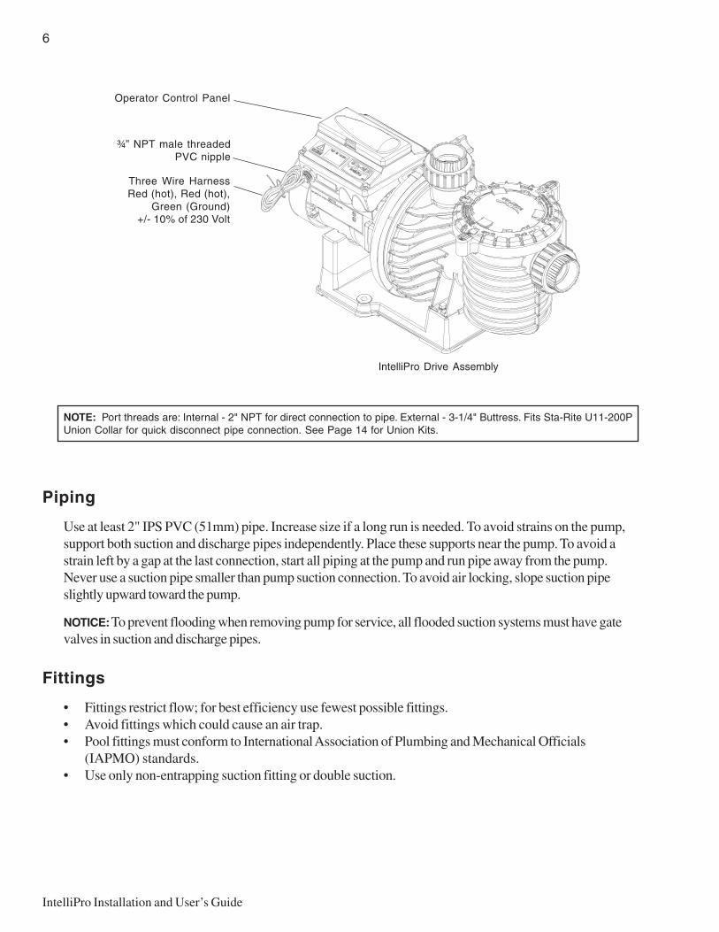
NOTE: Port threads are: Internal - 2" NPT for direct connection to pipe. External - 3-1/4" Buttress. Fits Sta-Rite U11-200PUnion Collar for quick disconnect pipe connection. See Page 14 for Union Kits.
Piping
Use at least 2" IPS PVC (51mm) pipe. Increase size if a long run is needed. To avoid strains on the pump,support both suction and discharge pipes independently. Place these supports near the pump. To avoid astrain left by a gap at the last connection, start all piping at the pump and run pipe away from the pump.Never use a suction pipe smaller than pump suction connection. To avoid air locking, slope suction pipeslightly upward toward the pump.
NOTICE: To prevent flooding when removing pump for service, all flooded suction systems must have gatevalves in suction and discharge pipes.
Fittings
• Fittings restrict flow; for best efficiency use fewest possible fittings.• Avoid fittings which could cause an air trap.• Pool fittings must conform to International Association of Plumbing and Mechanical Officials
(IAPMO) standards.• Use only non-entrapping suction fitting or double suction.
Three Wire HarnessRed (hot), Red (hot),
Green (Ground)+/- 10% of 230 Volt
¾” NPT male threadedPVC nipple
Operator Control Panel
IntelliPro Drive Assembly
7
IntelliPro Installation and User’s Guide
Wiring the IntelliPro
To connect the IntelliPro to an AC power source:
1. Make sure all electrical breakers and switches are turned off before wiring motor.
2. Make sure that the wiring voltage is 230 VAC.
3. Use #12 AWG for wire runs up to 100 feet and #10 AWG for lengths longer than 100 feet. When indoubt use a heavier gauge (larger diameter) wire. Heavier gauge will allow the motor to run cooler andmore efficient.
4. Make sure all electrical connections are clean and tight.
5. Cut the wires to the appropriate length so they do not overlap or touch when connected.
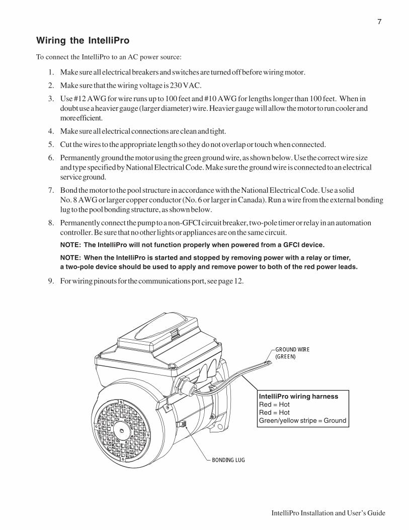
6. Permanently ground the motor using the green ground wire, as shown below. Use the correct wire sizeand type specified by National Electrical Code. Make sure the ground wire is connected to an electricalservice ground.
7. Bond the motor to the pool structure in accordance with the National Electrical Code. Use a solidNo. 8 AWG or larger copper conductor (No. 6 or larger in Canada). Run a wire from the external bondinglug to the pool bonding structure, as shown below.
8. Permanently connect the pump to a non-GFCI circuit breaker, two-pole timer or relay in an automationcontroller. Be sure that no other lights or appliances are on the same circuit.
NOTE: The IntelliPro will not function properly when powered from a GFCI device.
NOTE: When the IntelliPro is started and stopped by removing power with a relay or timer,a two-pole device should be used to apply and remove power to both of the red power leads.
9. For wiring pinouts for the communications port, see page 12.
GROUND WIRE(GREEN)
BONDING LUG
IntelliPro wiring harnessRed = HotRed = HotGreen/yellow stripe = Ground
8
IntelliPro Installation and User’s Guide
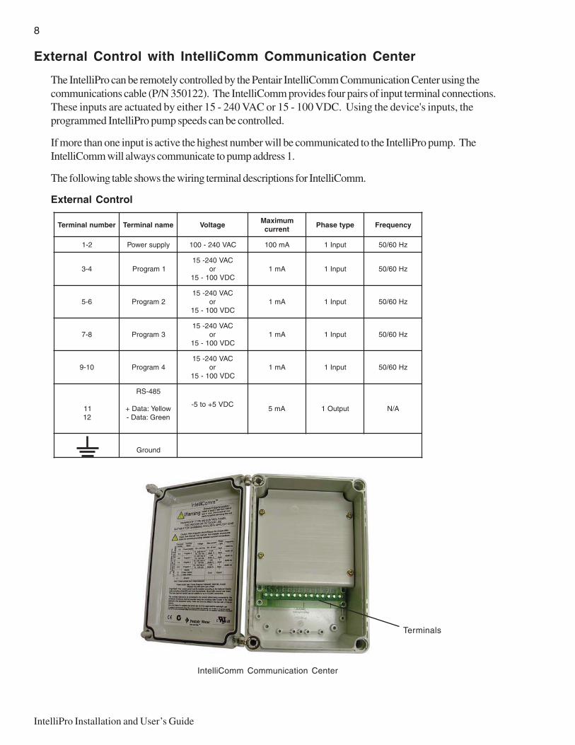
External Control with IntelliComm Communication Center
The IntelliPro can be remotely controlled by the Pentair IntelliComm Communication Center using thecommunications cable (P/N 350122). The IntelliComm provides four pairs of input terminal connections.These inputs are actuated by either 15 - 240 VAC or 15 - 100 VDC. Using the device's inputs, theprogrammed IntelliPro pump speeds can be controlled.
If more than one input is active the highest number will be communicated to the IntelliPro pump. TheIntelliComm will always communicate to pump address 1.
The following table shows the wiring terminal descriptions for IntelliComm.
External Control
rebmunlanimreT emanlanimreT egatloVmumixaMtnerruc
epytesahP ycneuqerF
2-1 ylppusrewoP CAV042-001 Am001 tupnI1 zH06/05
4-3 1margorPCAV042-51
roCDV001-51
Am1 tupnI1 zH06/05
6-5 2margorPCAV042-51
roCDV001-51
Am1 tupnI1 zH06/05
8-7 3margorPCAV042-51
roCDV001-51
Am1 tupnI1 zH06/05
01-9 4margorPCAV042-51
roCDV001-51
Am1 tupnI1 zH06/05
1121
584-SR
wolleY:ataD+neerG:ataD-
CDV5+ot5-Am5 tuptuO1 A/N
dnuorG
Terminals
IntelliComm Communication Center
9
IntelliPro Installation and User’s Guide
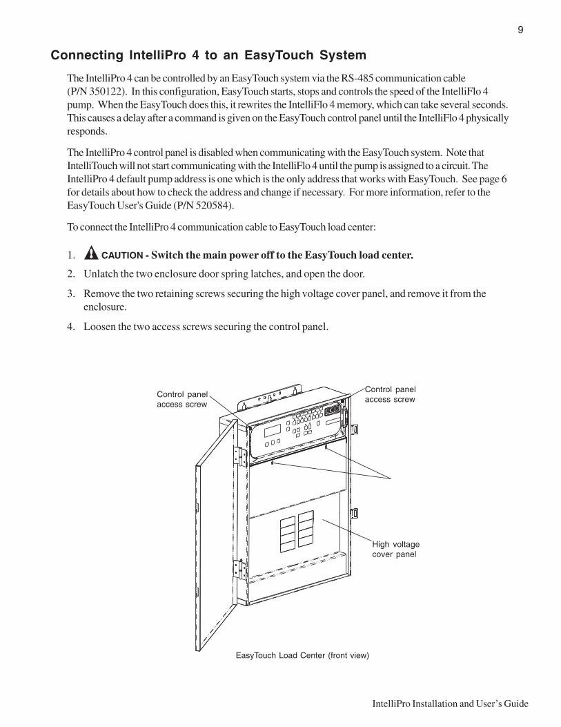
Connecting IntelliPro 4 to an EasyTouch System
The IntelliPro 4 can be controlled by an EasyTouch system via the RS-485 communication cable(P/N 350122). In this configuration, EasyTouch starts, stops and controls the speed of the IntelliFlo 4pump. When the EasyTouch does this, it rewrites the IntelliFlo 4 memory, which can take several seconds.This causes a delay after a command is given on the EasyTouch control panel until the IntelliFlo 4 physicallyresponds.
The IntelliPro 4 control panel is disabled when communicating with the EasyTouch system. Note thatIntelliTouch will not start communicating with the IntelliFlo 4 until the pump is assigned to a circuit. TheIntelliPro 4 default pump address is one which is the only address that works with EasyTouch. See page 6for details about how to check the address and change if necessary. For more information, refer to theEasyTouch User's Guide (P/N 520584).
To connect the IntelliPro 4 communication cable to EasyTouch load center:
1. CAUTION - Switch the main power off to the EasyTouch load center.
2. Unlatch the two enclosure door spring latches, and open the door.
3. Remove the two retaining screws securing the high voltage cover panel, and remove it from theenclosure.
4. Loosen the two access screws securing the control panel.
EasyTouch Load Center (front view)
Control panelaccess screw
Control panelaccess screw
High voltagecover panel
10
IntelliPro Installation and User’s Guide
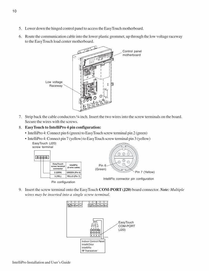
Pin configuration
EasyTouch (J20)screw terminal
hcuoTysaElanimretwercs
rotcennoc
olFilletnI)elbaceriw-2(
)NRG(2 )6niP(NEERG
)LEY(3 )7niP(OLLEY
Pin 6(Green)
Pin 7 (Yellow)
IntelliFlo connector pin configuration
Low voltageRaceway
Control panelmotherboard
5. Lower down the hinged control panel to access the EasyTouch motherboard.
6. Route the communication cable into the lower plastic grommet, up through the low voltage racewayto the EasyTouch load center motherboard.
7. Strip back the cable conductors ¼ inch. Insert the two wires into the screw terminals on the board.Secure the wires with the screws.
8. EasyTouch to IntelliPro 4 pin configuration:• IntelliPro 4: Connect pin 6 (green) to EasyTouch screw terminal pin 2 (green)• IntelliPro 4: Connect pin 7 (yellow) to EasyTouch screw terminal pin 3 (yellow)
9. Insert the screw terminal onto the EasyTouch COM-PORT (J20) board connector. Note: Multiplewires may be inserted into a single screw terminal.
EasyTouchCOM-PORT(J20)
Indoor Control PanelIntelliChlorIntelliFloRF Transceiver

11
IntelliPro Installation and User’s Guide
EasyTouch Load Center (front view)
Control panelaccess screw
Control panelaccess screw
High voltagecover panel
Retaining screw
10. Close the control panel into its original position and secure it with the two access screws.
11. Install the high voltage cover panel and secure it with the two retaining screws.
12. Close the EasyTouch load center front door. Fasten the two spring latches.
13. Switch the power on to the EasyTouch load center.
12
IntelliPro Installation and User’s Guide
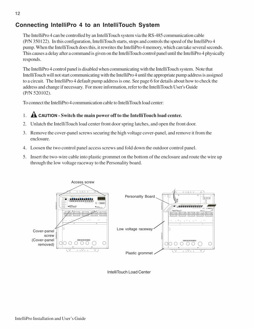
Connecting IntelliPro 4 to an IntelliTouch System
The IntelliPro 4 can be controlled by an IntelliTouch system via the RS-485 communication cable(P/N 350122). In this configuration, IntelliTouch starts, stops and controls the speed of the IntelliPro 4pump. When the IntelliTouch does this, it rewrites the IntelliPro 4 memory, which can take several seconds.This causes a delay after a command is given on the IntelliTouch control panel until the IntelliPro 4 physicallyresponds.
The IntelliPro 4 control panel is disabled when communicating with the IntelliTouch system. Note thatIntelliTouch will not start communicating with the IntelliPro 4 until the appropriate pump address is assignedto a circuit. The IntelliPro 4 default pump address is one. See page 6 for details about how to check theaddress and change if necessary. For more information, refer to the IntelliTouch User's Guide(P/N 520102).
To connect the IntelliPro 4 communication cable to IntelliTouch load center:
1. CAUTION - Switch the main power off to the IntelliTouch load center.
2. Unlatch the IntelliTouch load center front door spring latches, and open the front door.
3. Remove the cover-panel screws securing the high voltage cover-panel, and remove it from theenclosure.
4. Loosen the two control panel access screws and fold down the outdoor control panel.
5. Insert the two-wire cable into plastic grommet on the bottom of the enclosure and route the wire upthrough the low voltage raceway to the Personality board.
IntelliTouch Load Center
Personality Board
Low voltage raceway
Plastic grommet
Cover-panelscrew
(Cover-panelremoved)
Access screw
13
IntelliPro Installation and User’s Guide
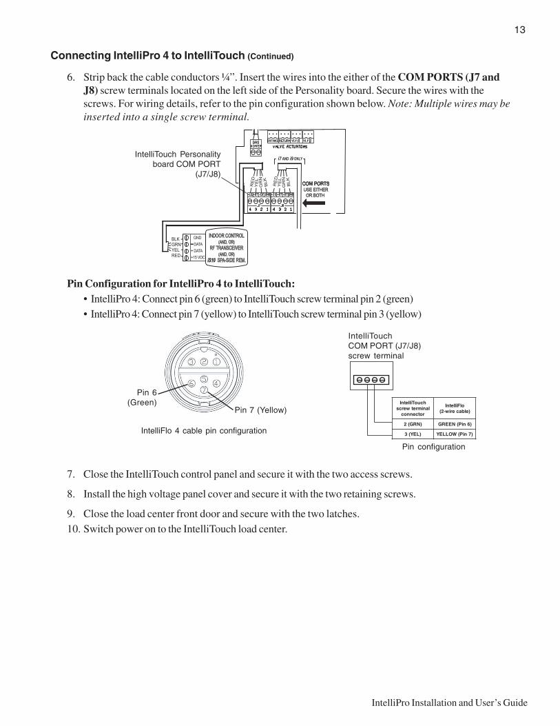
Connecting IntelliPro 4 to IntelliTouch (Continued)
6. Strip back the cable conductors ¼”. Insert the wires into the either of the COM PORTS (J7 andJ8) screw terminals located on the left side of the Personality board. Secure the wires with thescrews. For wiring details, refer to the pin configuration shown below. Note: Multiple wires may beinserted into a single screw terminal.
Pin Configuration for IntelliPro 4 to IntelliTouch:• IntelliPro 4: Connect pin 6 (green) to IntelliTouch screw terminal pin 2 (green)• IntelliPro 4: Connect pin 7 (yellow) to IntelliTouch screw terminal pin 3 (yellow)
7. Close the IntelliTouch control panel and secure it with the two access screws.
8. Install the high voltage panel cover and secure it with the two retaining screws.
9. Close the load center front door and secure with the two latches.10. Switch power on to the IntelliTouch load center.
Pin configuration
IntelliTouchCOM PORT (J7/J8)screw terminal
hcuoTilletnIlanimretwercs
rotcennoc
olFilletnI)elbaceriw-2(
)NRG(2 )6niP(NEERG
)LEY(3 )7niP(WOLLEY
BLKGRNYELRED
IntelliTouch Personalityboard COM PORT
(J7/J8)
Pin 6(Green)
Pin 7 (Yellow)
IntelliFlo 4 cable pin configuration

14
IntelliPro Installation and User’s Guide
Blank Page
15
IntelliPro Installation and User’s Guide
Section 3Operation
This section describes how to use the IntelliPro pump control panel.
Setting the pump preset speed
IntelliPro operates using one of the preset speeds. Use the speed buttons to select the preset speeds.
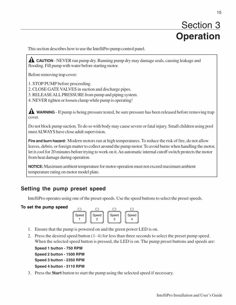
To set the pump speed
1. Ensure that the pump is powered on and the green power LED is on.
2. Press the desired speed button (1- 4) for less than three seconds to select the preset pump speed.When the selected speed button is pressed, the LED is on. The pump preset buttons and speeds are:
Speed 1 button - 750 RPM
Speed 2 button - 1500 RPM
Speed 3 button - 2350 RPM
Speed 4 button - 3110 RPM
3. Press the Start button to start the pump using the selected speed if necessary.
CAUTION - NEVER run pump dry. Running pump dry may damage seals, causing leakage andflooding. Fill pump with water before starting motor.
Before removing trap cover:
1. STOP PUMP before proceeding.2. CLOSE GATE VALVES in suction and discharge pipes.3. RELEASE ALL PRESSURE from pump and piping system.4. NEVER tighten or loosen clamp while pump is operating!
WARNING - If pump is being pressure tested, be sure pressure has been released before removing trapcover.
Do not block pump suction. To do so with body may cause severe or fatal injury. Small children using poolmust ALWAYS have close adult supervision.
Fire and burn hazard: Modern motors run at high temperatures. To reduce the risk of fire, do not allowleaves, debris, or foreign matter to collect around the pump motor. To avoid burns when handling the motor,let it cool for 20 minutes before trying to work on it. An automatic internal cutoff switch protects the motorfrom heat damage during operation.
NOTICE: Maximum ambient temperature for motor operation must not exceed maximum ambienttemperature rating on motor model plate.
16
IntelliPro Installation and User’s Guide
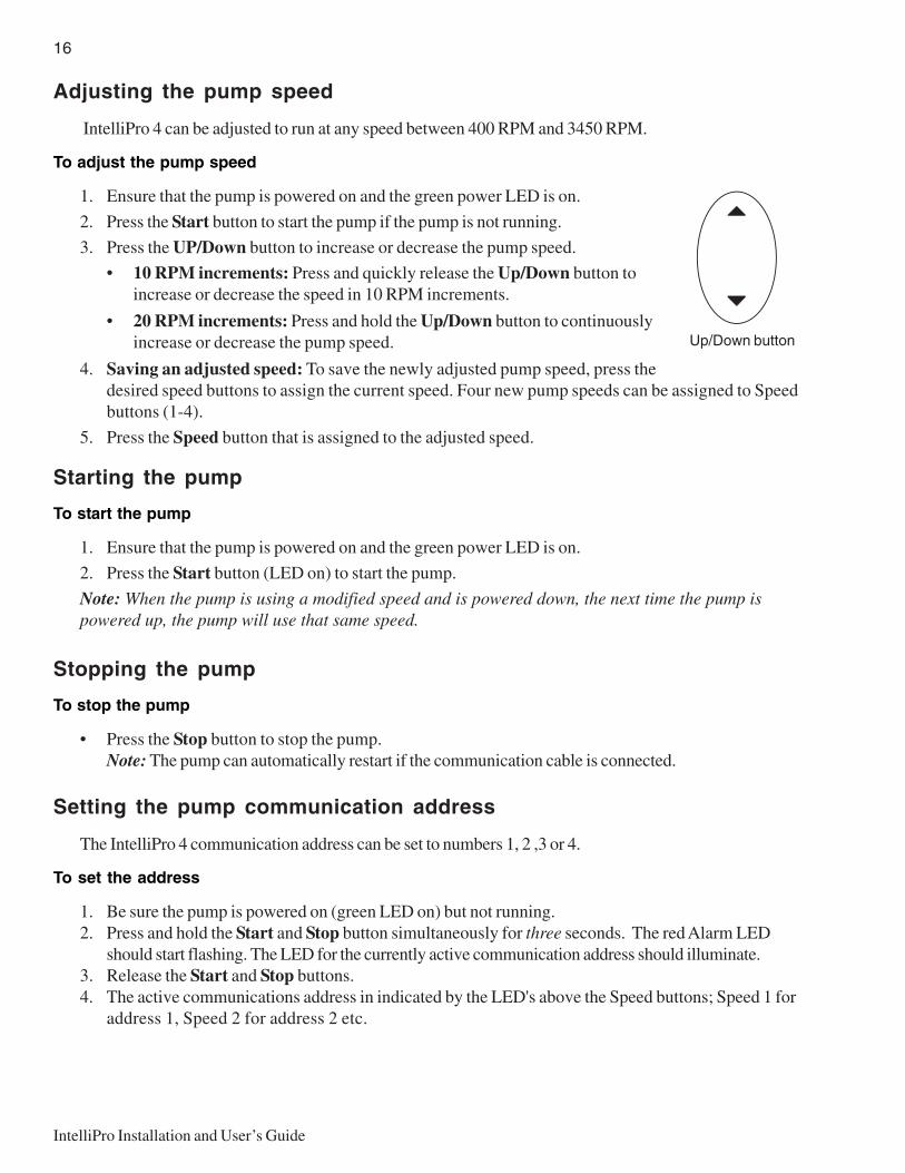
Adjusting the pump speed
IntelliPro 4 can be adjusted to run at any speed between 400 RPM and 3450 RPM.
To adjust the pump speed
1. Ensure that the pump is powered on and the green power LED is on.
2. Press the Start button to start the pump if the pump is not running.
3. Press the UP/Down button to increase or decrease the pump speed.
• 10 RPM increments: Press and quickly release the Up/Down button toincrease or decrease the speed in 10 RPM increments.
• 20 RPM increments: Press and hold the Up/Down button to continuouslyincrease or decrease the pump speed.
4. Saving an adjusted speed: To save the newly adjusted pump speed, press thedesired speed buttons to assign the current speed. Four new pump speeds can be assigned to Speedbuttons (1-4).
5. Press the Speed button that is assigned to the adjusted speed.
Starting the pump
To start the pump
1. Ensure that the pump is powered on and the green power LED is on.
2. Press the Start button (LED on) to start the pump.
Note: When the pump is using a modified speed and is powered down, the next time the pump ispowered up, the pump will use that same speed.
Stopping the pump
To stop the pump
• Press the Stop button to stop the pump.Note: The pump can automatically restart if the communication cable is connected.
Setting the pump communication address
The IntelliPro 4 communication address can be set to numbers 1, 2 ,3 or 4.
To set the address
1. Be sure the pump is powered on (green LED on) but not running.2. Press and hold the Start and Stop button simultaneously for three seconds. The red Alarm LED
should start flashing. The LED for the currently active communication address should illuminate.3. Release the Start and Stop buttons.4. The active communications address in indicated by the LED's above the Speed buttons; Speed 1 for
address 1, Speed 2 for address 2 etc.
Up/Down button

17
IntelliPro Installation and User’s Guide
Setting the pump communication address (Continued)
5. Change the active address by pressing the appropriate Speed button (Speed 1, Speed 2, Speed 3or Speed 4) while the Alarm LED is flashing.
6. Once the desired address has been selected, press and hold the Start and Stop buttons again. TheAlarm LED will stop flashing and the Speed LED for the previously selected run speed willilluminate.
7. Release the Start and Stop buttons.
Resetting the pump to factory defaults
The IntelliPro pump can be reset to the factory default settings. All previously adjusted pump speeds that weresaved will be erased.
To reset the pump to the factory default settings:
1. Ensure that the pump is powered on and the green power LED is on.
2. Press the Stop button to stop the pump.
3. Press and hold all of the four Speed buttons simultaneously for three seconds. Power off the driveand reenergize. The default settings will be in effect.
18
IntelliPro Installation and User’s Guide
Priming the pump for the first time or after service
Before the IntelliPro pump is started for the first time it must be primed. To prime a pump means filling thepump and suction pipe with water. This process evacuates the air from all the suction lines and the pump. Itmay take several minutes to prime depending on the depth of water, pipe size and length. It is easier toprime a pump if you allow all the air to escape from the pump and pipes. The water cannot enter unless theair can escape. Pumps do not hold prime, the pool piping system has that task.
CAUTION - To avoid permanent damage to the IntelliPro pump, before starting the pump, fill theIntelliPro housing strainer with water so that the pump will prime correctly. If there is no water in the stainer thepump will not prime.
• NEVER run the pump dry! Running the pump dry may damage the seals, causing leakage andflooding!
• Do not add chemicals to the system directly in front of pump suction. Adding undiluted chemicalsmay damage the pump and will void the warranty.
• Open gate valves before starting system.• Pump will prime itself when used in flooded suction system.• Be sure to release all air from filter and piping system.• The IntelliPro pump is a variable speed pump. Typically the lower speeds are used for filtration and
heating. The higher speeds can be used for spa jets, water features, and priming.
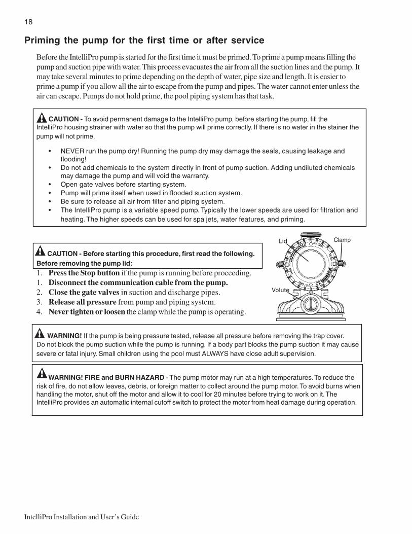
CAUTION - Before starting this procedure, first read the following.Before removing the pump lid:1. Press the Stop button if the pump is running before proceeding.1. Disconnect the communication cable from the pump.2. Close the gate valves in suction and discharge pipes.3. Release all pressure from pump and piping system.4. Never tighten or loosen the clamp while the pump is operating.
WARNING! If the pump is being pressure tested, release all pressure before removing the trap cover.Do not block the pump suction while the pump is running. If a body part blocks the pump suction it may causesevere or fatal injury. Small children using the pool must ALWAYS have close adult supervision.
WARNING! FIRE and BURN HAZARD - The pump motor may run at a high temperatures. To reduce therisk of fire, do not allow leaves, debris, or foreign matter to collect around the pump motor. To avoid burns whenhandling the motor, shut off the motor and allow it to cool for 20 minutes before trying to work on it. TheIntelliPro provides an automatic internal cutoff switch to protect the motor from heat damage during operation.
Lid Clamp
Volute

19
IntelliPro Installation and User’s Guide
Priming the pump for the first time or after service (Continued)
Priming the Pump
• Release all pressure from filter, pump, and piping system; see the filter owner’s manual.• In a flooded suction system (water source higher than pump), the IntelliPro pump will prime itself
when suction and discharge valves are opened.• If the IntelliPro pump is not in a flooded suction system, unscrew and remove lid cover; fill the and
pump with water.• Do not lubricate the trap cover o-ring. The original equipment o-ring contains a permanent internal
lubricant.NOTICE: If you replace the o-ring with a non-internally lubricated o-ring, you may need to apply a siliconebased lubricant.
• Clean and inspect o-ring; reinstall on trap cover.• Replace trap cover on trap; turn clockwise to tighten cover.
NOTICE: Tighten the pump lid by hand only (no wrenches)!
Pump should prime now. Priming time will depend on vertical length of suction lift and horizontal length ofsuction piping. If pump does not prime, make sure that all valves are open, suction pipe end is under water,pump suction is below water level, and that there are no leaks in suction pipe.
To prime the IntelliPro pump:
1. Turn the pump clamp and lid in a counterclockwise direction until it stopsand remove them.
2. Fill the pump strainer pot with water.
3. Reinstall the pump clamp and lid onto the strainer pot. The pump is nowready to prime.
4. Make sure all electrical connections are clean and tight.
5. Open the air release valve on the filter, and stand clear of the filter.
6. Switch the IntelliPro pump on at the circuit breaker. Ensure that thegreen power light is on.
7. Press the Speed 1 button to select the pump speed of 750 RPM.
8. Press the Start button to start the pump. Use the Up/Down button to increase the speed as necessaryto prime the pump.
9. When water comes out of the air release valve, close the valve. The system should now be circulating waterback to the pool without air bubbles showing in either the hair and lint pot or at the pool return fittings.
10. Use the Up/Down button to adjust the operating speed as desired.
Top view
Lid Clamp
Volute
20
IntelliPro Installation and User’s Guide
Storage/Winterizing
WARNING - Explosion hazard. Purging the system with compressed air can cause components toexplode, with risk of severe injury or death to anyone nearby. Use only a low pressure (below 5 PSI),high volume blower when air purging the pump, filter, or piping.
NOTICE: Allowing the pump to freeze will damage pump and void warranty!
NOTICE: Do not use anti-freeze solutions (except propylene glycol) in your pool/spa system. Propyleneglycol is non-toxic and will not damage plastic system components; other anti-freezes are highly toxic andmay damage plastic components in the system.
• Drain all water from pump and piping when expecting freezing temperatures or when storing pumpfor a long time (see instructions below).
• Keep motor dry and covered during storage.• To avoid condensation/corrosion problems, do not cover pump with plastic.
For outdoor/unprotected installations:
1. Gravity drain system as far as possible.2. Protect areas which retain water with non-toxic propylene glycol antifreeze (“RV antifreeze”).3. Enclose entire system in a weatherproof enclosure.4. To avoid condensation/corrosion damage, allow ventilation; do not wrap system in plastic.5. Use a 40% propylene glycol/60% water solution to protect pump to -50°F (-46°C).
Draining Pump
CAUTION - To avoid dangerous or fatal electrical shock hazard, turn OFF power to motor before drainingpump.
1. Pump down water level below all inlets to the pool.
2. Remove the trap cover and use low pressure air to blow the accumulated water from the pipingsystem. Lugs have been provided on the trap lid to use a lever or pry bar for loosening.
3. Cap the inlet piping after draining to keep water out of the pipes.
4. To prevent the pump from freezing, remove the trap cover and drain the tank body through the drainplugs (Key No. 19). Clean the pump and trap basket thoroughly; replace the trap cover.
NOTICE: Hand tighten the trap cover - Do not use a wrench! Use a rubber mallet only if necessaryto remove the cover - If the pump is not anchored, use caution not to break or damage the attachedpiping.
5. Be sure the motor is kept dry and covered.

21
IntelliPro Installation and User’s Guide
Startup For Winterized Equipment
1. Remove any temporary weather protection placed around system.
2. Follow the filter manufacturer’s instructions for reactivation of the filter.
3. Inspect all electrical wiring for damage or deterioration over the shutdown period. Have a qualifiedserviceman repair wiring as needed.
4. Inspect and tighten all watertight connections.
5. Open all valves in suction and return piping.
6. Remove any winterizing plugs in piping system.
7. Drain all antifreeze from system.
8. Close all drain valves and replace all drain plugs in piping system.
9. Prime pump according to instructions on Page x.
Pump Service
• Pump should only be serviced by qualified personnel.
• For best results, use only genuine Sta-Rite factory parts.
• Be sure to prime pump (page 19) before starting.
CAUTION - Before removing clamp or trap cover:
1. STOP PUMP before proceeding.
2. DISCONNECT THE COMMUNICATIONS CABLE from the pump.
3. CLOSE GATE VALVES in suction and discharge pipes.
4. RELEASE ALL PRESSURE from pump and piping system.
5. NEVER tighten or loosen clamp while pump is operating!
WARNING - To avoid dangerous or fatal electrical shock hazard, turn OFF power to motor before workingon pump or motor. No lubrication or regular maintenance is needed beyond reasonable care and periodiccleaning of the strainer basket.

22
IntelliPro Installation and User’s Guide
Blank Page

23
IntelliPro Installation and User’s Guide
Section 4User Maintenance
The following information describes how to service and maintain the IntelliPro pump.
Pump Strainer Basket
The strainer, sometimes referred to as the “Hair and Lint Pot,” is in front of the pump. Inside there is abasket which must be kept clean of leaves and debris at all times. View the basket through the top seethrough lid to inspect for leaves and debris.
Regardless of the length of time between filter cleaning, it is most important to visually inspect the hair and lintpot basket at least once a week. A dirty basket will reduce the efficiency of the filter and possibly the heater.
WARNING — DO NOT open the strainer pot if pump fails to prime or if pump has been operating withoutwater in the strainer pot. Pumps operated in these circumstances may experience a build upof vapor pressure and may contain scalding hot water. Opening the pump may cause seriouspersonal injury. In order to avoid the possibility of personal injury, make sure the suction anddischarge valves are open and that the strainer pot is cool to the touch, then open withextreme caution.
CAUTION — To prevent damage to the pump and filter and for proper operation of the system, cleanpump strainer and skimmer baskets regularly.
Pump Strainer Basket Service
If the IntelliPro pump is installed below the water level of the pool,close the return and suction lines before opening the hair and lint poton the pump.
1. Press the Stop button to stop the pump and switch off the pumpat the circuit breaker.
2. Disconnect the communication cable from the IntelliPro pump.
3. Relieve pressure in the system.
4. Turn the clamp and lid in a counterclockwise direction until itstops.
5. Remove the clamp and lid.
6. Remove the basket and put the debris into the trash and rinse outthe basket. If the basket is cracked, replace the basket.
7. Replace the basket and fill the pump pot and volute with waterup to the inlet port.
8. Clean the cover, o-ring, and sealing surface of the pump pot. Greasethe o-ring with Teflon or silicone lubricant.
9. Reinstall the lid by placing the clamp and the lid on the pot.
Pot clamp
Lid
O-ring lid
Basket
Pot volute

24
IntelliPro Installation and User’s Guide
Motor Service
1. Protect from heat:
• Shade the motor and controller from the sun.• Any enclosure must be well ventilated to prevent overheating. Particular attention should be paid to the
motor fan cover and the cooling fins between the drive and the motor.• Provide ample cross ventilation.
2. Protect against dirt:
• Protect from any foreign matter or splashing water.• Do not store (or spill) pool chemicals near the motor.• Avoid sweeping or stirring up dust near the motor while it is operating.• If a motor has been damaged by dirt it voids the motor warranty.
3. Protect against moisture:
• Protect from splashing pool water.• Protect from the weather.• Protect from lawn sprinklers.• If a motor has become wet - let it dry before operating. Do not allow the pump to operate if it has been
flooded.• If a motor has been damaged by water it voids the motor warranty.
Note: DO NOT wrap motor and controller with plastic or other air tight materials. The motor andcontroller may be covered, but not wrapped in plastic, during a storm, for winter storage, etc., butnever when operating, or expecting operation.
Pump Strainer Basket Service (Continued)
10. Ensure that the lid o-ring is properly placed. Seat the clamp and lid thenturn clockwise until the handles are horizontal as shown.
11. Reconnect the communication cable to the pump if required.
12. Switch the power ON at the circuit breaker. Reset the pool time clockto the correct time.
WARNING — FILTER OPERATES UNDER HIGH PRESSURE. WHEN ANY PART OF THE CIRCULATING SYSTEM (e.g., LOCK RING, PUMP, FILTER, VALVES, ETC.) IS SERVICED, AIR CAN ENTER THE SYSTEM AND BECOME PRESSURIZED. PRESSURIZED AIR CAN CAUSE THE LID TO BLOW OFF WHICH CAN RESULTIN SEVERE INJURY, DEATH, OR PROPERTY DAMAGE. TO AVOID THISPOTENTIAL HAZARD, FOLLOW THESE INSTRUCTIONS.
13. Prime the pump. See page 19 for details.
Lid Clamp
Volute
25
IntelliPro Installation and User’s Guide
Priming the pump after service
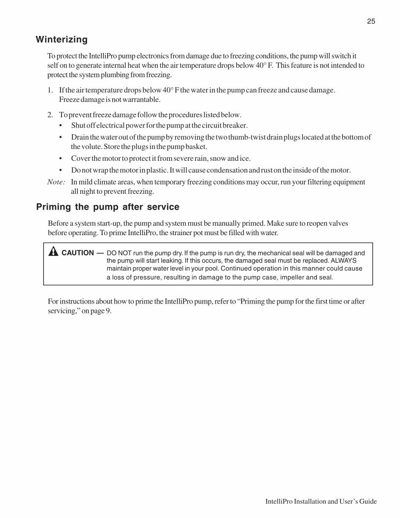
Before a system start-up, the pump and system must be manually primed. Make sure to reopen valvesbefore operating. To prime IntelliPro, the strainer pot must be filled with water.
CAUTION — DO NOT run the pump dry. If the pump is run dry, the mechanical seal will be damaged andthe pump will start leaking. If this occurs, the damaged seal must be replaced. ALWAYSmaintain proper water level in your pool. Continued operation in this manner could causea loss of pressure, resulting in damage to the pump case, impeller and seal.
For instructions about how to prime the IntelliPro pump, refer to “Priming the pump for the first time or afterservicing,” on page 9.
Winterizing
To protect the IntelliPro pump electronics from damage due to freezing conditions, the pump will switch itself on to generate internal heat when the air temperature drops below 40° F. This feature is not intended toprotect the system plumbing from freezing.
1. If the air temperature drops below 40° F the water in the pump can freeze and cause damage.Freeze damage is not warrantable.
2. To prevent freeze damage follow the procedures listed below.• Shut off electrical power for the pump at the circuit breaker.
• Drain the water out of the pump by removing the two thumb-twist drain plugs located at the bottom ofthe volute. Store the plugs in the pump basket.
• Cover the motor to protect it from severe rain, snow and ice.
• Do not wrap the motor in plastic. It will cause condensation and rust on the inside of the motor.
Note: In mild climate areas, when temporary freezing conditions may occur, run your filtering equipmentall night to prevent freezing.

26
IntelliPro Installation and User’s Guide
Blank Page

27
IntelliPro Installation and User’s Guide
Section 5Removal and Replacement
The following information describes how to remove and install the drive assembly and to repair a worn ordamaged shaft seal.
Note: Before installing this product, read and follow all warning notices and instructions on page ii.
Pump Disassembly
WARNING — Always disconnect power to the pool pump at the circuit breaker and disconnect thecommunication cable before servicing the pump. Failure to do so could result in death orserious injury to serviceman, pool users or others due to electric shock.
Read all servicing instructions before working on the pump.
WARNING — DO NOT open the strainer pot if pump fails to prime or if pump has been operating withoutwater in the strainer pot. Pumps operated in these circumstances may experience a build upof vapor pressure and may contain scalding hot water. Opening the pump may cause seriouspersonal injury. In order to avoid the possibility of personal injury, make sure the suction anddischarge valves are open and strainer pot temperature is cool to touch, then open withextreme caution.
CAUTION — Be sure not to scratch or mar the polished shaft seal faces; seal will leak if faces aredamaged.
Required tools:
• ½ inch open end wrench.
• 7/16 inch open end wrench.
• Flat blade screwdriver.
Drive Assembly Removal and Installation
To remove the IntelliPro drive assembly and control panel from the pump’s motor assembly:
WARNING - To avoid dangerous or fatal electrical shock hazard, switch OFF power to motor before workingon pump or motor.
1. Disconnect the RS-485 communication cable from the pump.
2. Open the control panel cover.
28
IntelliPro Installation and User’s Guide
Drive Assembly Removal and Installation (Continued)
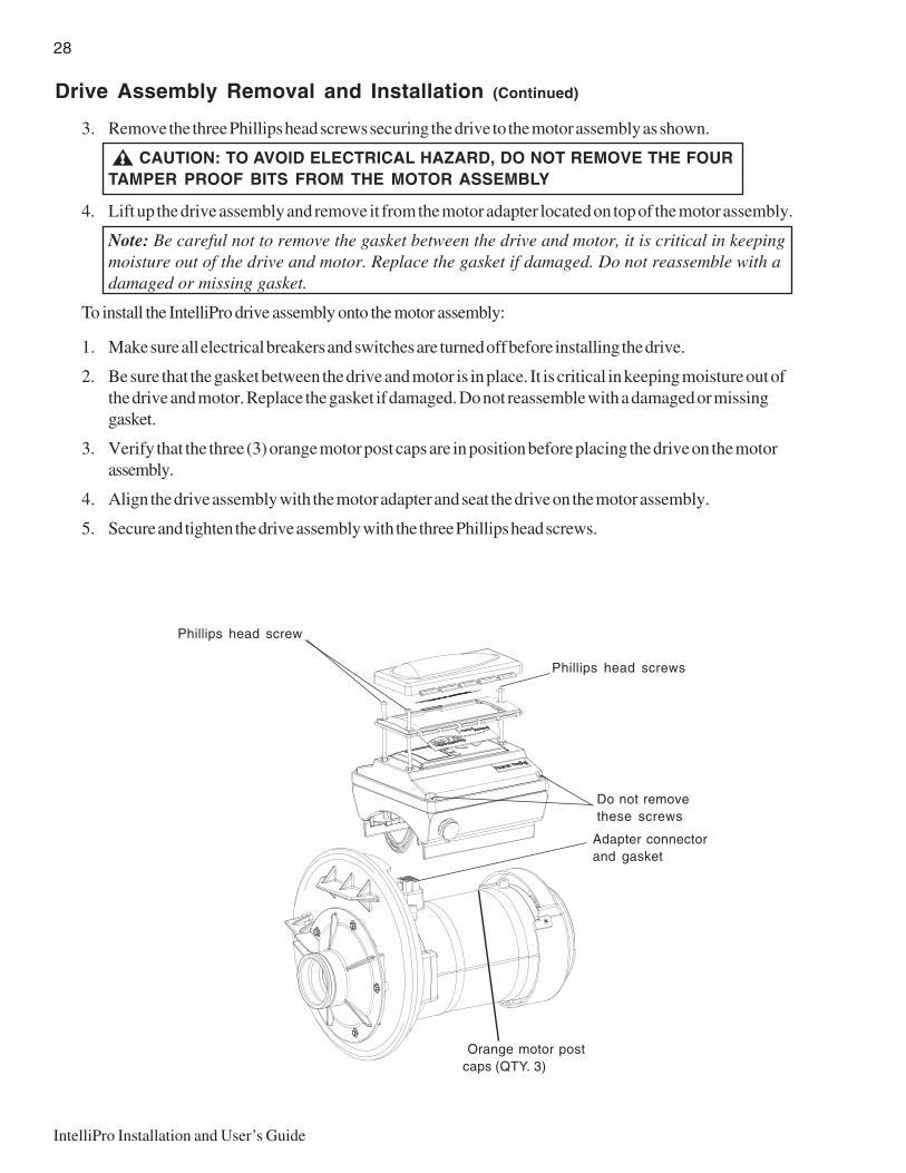
3. Remove the three Phillips head screws securing the drive to the motor assembly as shown.
CAUTION: TO AVOID ELECTRICAL HAZARD, DO NOT REMOVE THE FOURTAMPER PROOF BITS FROM THE MOTOR ASSEMBLY
4. Lift up the drive assembly and remove it from the motor adapter located on top of the motor assembly.
Note: Be careful not to remove the gasket between the drive and motor, it is critical in keepingmoisture out of the drive and motor. Replace the gasket if damaged. Do not reassemble with adamaged or missing gasket.
To install the IntelliPro drive assembly onto the motor assembly:
1. Make sure all electrical breakers and switches are turned off before installing the drive.
2. Be sure that the gasket between the drive and motor is in place. It is critical in keeping moisture out ofthe drive and motor. Replace the gasket if damaged. Do not reassemble with a damaged or missinggasket.
3. Verify that the three (3) orange motor post caps are in position before placing the drive on the motorassembly.
4. Align the drive assembly with the motor adapter and seat the drive on the motor assembly.
5. Secure and tighten the drive assembly with the three Phillips head screws.
Phillips head screws
Phillips head screw
Do not removethese screws
Adapter connectorand gasket
Orange motor postcaps (QTY. 3)

29
IntelliPro Installation and User’s Guide
Pump Disassembly/Removing Old Seal
WARNING - To avoid dangerous or fatal electrical shock hazard, switch OFF power to motor beforeworking on pump or motor.
CAUTION - Be sure gate valves on suction and return piping are closed and release all pressure byopening all vents before starting work.
Release all pressure by opening all vents before starting.
1. Drain the pump by removing the drain plugs on the bottom of the pump body and trap body.
2. Be sure there is no pressure in the trap body. Remove the cover (unscrew by turning the handle ringcounterclockwise).
3. Remove the clamp holding the pump halves together. The motor and seal plate assembly can now bepulled away from the pump body.
4. Remove the five screws and washers holding the diffuser to the seal plate. Remove the diffuser.
5. Hold the shaft with a 7/16" open-ended wrench on the motor shaft flats.
6. Unscrew the impeller from the shaft (turn counterclockwise when facing it). Note: On models withan impeller screw: Remove the impeller screw (left hand thread - turn clockwise) and gasketbefore removing the impeller. Inspect the gasket for damage, cracks, etc. Replace if damaged.
7. Pull the rotating member of the seal off the impeller sleeve - Clean the sleeve.
8. Remove the four screws holding the seal plate to the motor.
9. Place the seal plate face down on flat surface and tap out the ceramic seat.
10. Clean the seal cavity in the seal plate and clean the motor shaft.
O-ring
Seal plate
O-ringMotor Bolt (4x)
Impeller (not shown)
Impeller screw
Diffuser
30
IntelliPro Installation and User’s Guide
Pump Reassembly/Installing New Seal
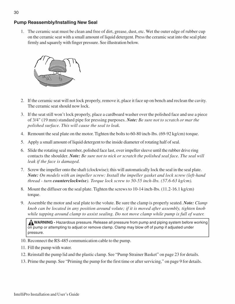
1. The ceramic seat must be clean and free of dirt, grease, dust, etc. Wet the outer edge of rubber cupon the ceramic seat with a small amount of liquid detergent. Press the ceramic seat into the seal platefirmly and squarely with finger pressure. See illustration below.
2. If the ceramic seat will not lock properly, remove it, place it face up on bench and reclean the cavity.The ceramic seat should now lock.
3. If the seat still won’t lock properly, place a cardboard washer over the polished face and use a pieceof 3/4" (19 mm) standard pipe for pressing purposes. Note: Be sure not to scratch or mar thepolished surface. This will cause the seal to leak.
4. Remount the seal plate on the motor. Tighten the bolts to 60-80 inch-lbs. (69-92 kg/cm) torque.
5. Apply a small amount of liquid detergent to the inside diameter of rotating half of seal.
6. Slide the rotating seal member, polished face last, over impeller sleeve until the rubber drive ringcontacts the shoulder. Note: Be sure not to nick or scratch the polished seal face. The seal willleak if the face is damaged.
7. Screw the impeller onto the shaft (clockwise); this will automatically lock the seal in the seal plate.Note: On models with an impeller screw: Install the impeller gasket and lock screw (left-handthread - turn counterclockwise). Torque lock screw to 50-55 inch-lbs. (57.6-63 kg/cm).
8. Mount the diffuser on the seal plate. Tighten the screws to 10-14 inch-lbs. (11.2-16.1 kg/cm)torque.
9. Assemble the motor and seal plate to the volute. Be sure the clamp is properly seated. Note: Clampknob can be located in any position around volute; if it is moved after assembly, tighten knobwhile tapping around clamp to assist sealing. Do not move clamp while pump is full of water.
WARNING - Hazardous pressure. Release all pressure from pump and piping system before workingon pump or attempting to adjust or remove clamp. Clamp may blow off of pump if adjusted underpressure.
10. Reconnect the RS-485 communication cable to the pump.
11. Fill the pump with water.
12. Reinstall the pump lid and the plastic clamp. See “Pump Strainer Basket” on page 23 for details.
13. Prime the pump. See “Priming the pump for the first time or after servicing,” on page 9 for details.

31
IntelliPro Installation and User’s Guide
Illustrated Parts List
1 2
6
46
16
913
1512
22
14
2627172578
21333220
24 23 5
30
3119
29
28
10
18
11
Cable(not shown)
3
.oNmetI .ytQ rebmuNtraP noitpircseD
1 1 a73-91c PMALC-V
2 1 22-63cw BONK,PMALC
3 1 221053 )NWOHSTON(DNOC2TF05LBC
4 3 701053 SS8-81SMHP"4/13X42-01
5 2 263-9U 132-2#GNIR-O
6 1 092753 KLB,YSSARTNCRVC
7 5 ss12-34u REHSAWHTOOTTXE8#
8 5 ss229-03u RESUFFIDWERCS
9 1 801053 EVIRDOLFILLETNITEKSAG
01 1 a822-9u GNIR-O
11 1 P491-301c ETALPLAES
21 4 SS99-03U daeHcoS"1X61-8/3PACRCS
31 3 241053 RECAPSPAC
41 1 11-53C DAPROTOM
51 4 492753 DFVMSMPWK2.3RTM
61 1 982753 KLBOLFILLETNIDPS4EVIRD
.oNmetI .ytQ rebmuNtraP noitpircseD
71 1 0806-73373 WERCSRELLEPMI
81 1 473-9U GNIR_O
91 1 0441-50553 .D.I53.6.D.O09.6GNIR-O
02 2 953-9U GULPNIARDGNIR-O
12 2 819-03u XEHOL-IHGLNI1X41-61/5RCS
22 1 P87-4C ESAB
32 2 P691-11U RETPADATPN"2
42 2 SP002-11U RALLOCNOINU
52 1 P172-1c RESUFFID
62 2 8200-00473 NOTIV,LAESTFAHS
72 1 ALP832-501C YLBMESSARELLEPMI
82 1 9000-15371 NI61/1TFAHSPMUPREGNILS
92 1 S1110-70371 *YLBMESSAREVOCPART
03 1 S0110-70371 **YLBMESSAYDOBKNAT
13 2 P85-8C TEKSABPART
23 2 P029-87U GULPNIARD
33 2 SS14-34u WORRANBEPYT61/5REHSAWNote(*) Includes TRAP COVER, TRAP RING AND COVER O-RING(**) Includes TRAP BODY, BASKET, DRAIN PLUGS AND TRAP COVER ASSEMBLY
32
IntelliPro Installation and User’s Guide
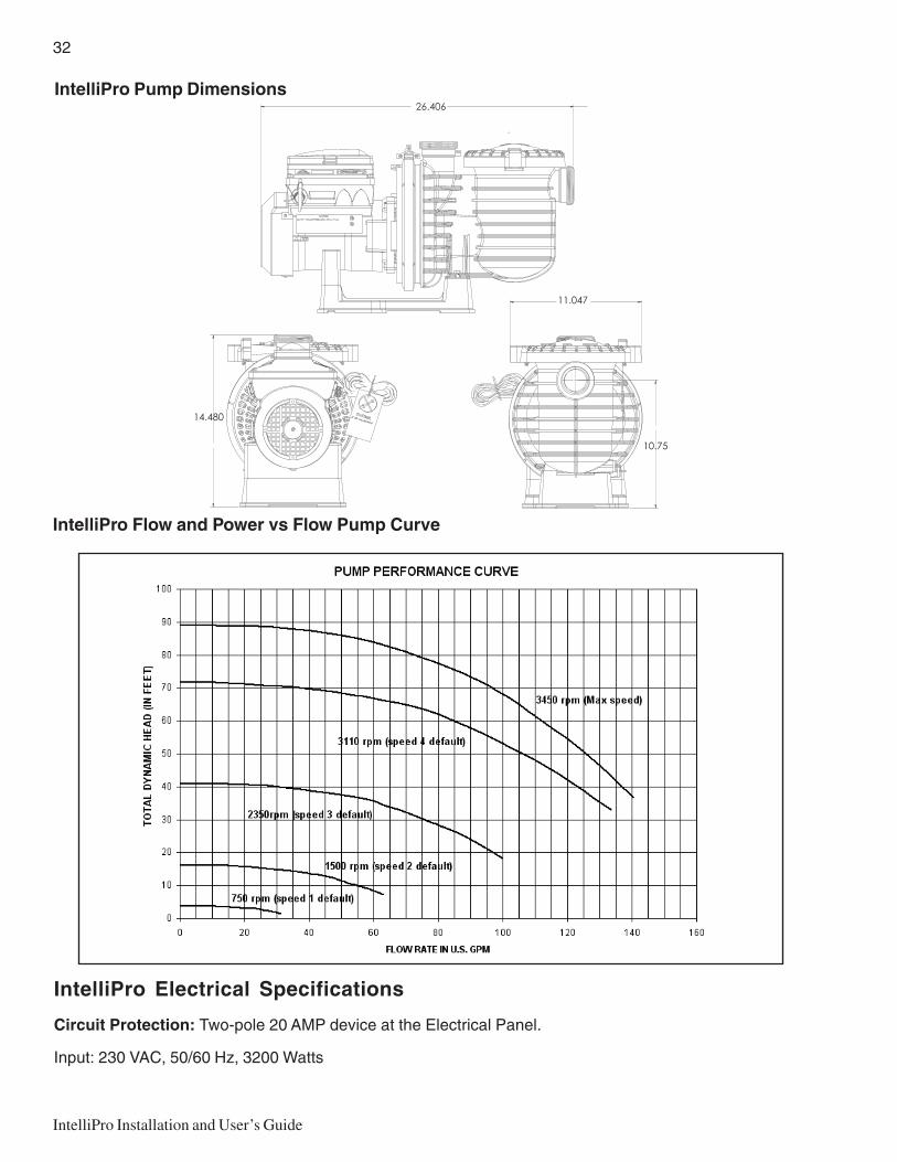
IntelliPro Pump Dimensions
IntelliPro Electrical Specifications
Circuit Protection: Two-pole 20 AMP device at the Electrical Panel.
Input: 230 VAC, 50/60 Hz, 3200 Watts
IntelliPro Flow and Power vs Flow Pump Curve
14.480
26.406
10.75
11.047

33
IntelliPro Installation and User’s Guide
Warning and Alarm conditions
The IntelliPro alarms and warnings are indicated by flashing LEDs on the control panel. For example, if a“Drive Temperature” warning occurs, the LED will blink two times, then Off, then blink two times. Thissequence is repeated until the condition is cleared.
• Warning condition: If a warning condition occurs the pump will be continue to run but at a reducedspeed. The Green LED executes a sequence of blinks to indicate which alarm or warning hasoccurred.
• Alarm condition: If an alarm condition occurs the pump will drive stop running. The red LEDflashes continuously to indicate the presence of an alarm. The alarm LEDs will reset when thecondition clears.
Alarm and warning LED sequence
Section 6Troubleshooting
CAUTION: Before installing this product, read and follow all warning notices and instructions on page ii.
ehtemitforebmuNknilblliwDEL
mralA noitpircseD noitcA
2 gninraWerutarepmeTevirD erutarepmetevirdevissecxE sahnafrotomehterusnE.1.noitalitnevrofaeraetauqeda
.loocotwolladnarotompotS.2
otdeepsrehgihatarotomnuR.3.wolfriagniloocevorpmi
5 mralanwonknU eruliafnortcelE .pmupteserotrewopelcyC.1.evirdecalpeR.2
6 mralAerutarepmeTevirD erutarepmetevirdevissecxE sahnafrotomehterusnE.1.noitalitnevrofaeraetauqeda
otdeepsrehgihatarotomnuR.2.wolfriagniloocevorpmi
7 mralAtuOrewoP wolegatlovylppuS .egatlovylppusreporperusnE
8 mralAtnerrucrevO tnerrucevirdevissecxE lacinahcem/diulfenimaxE.1.daolrevofoecruosrofmetsys
dnarotomezigrene-eD.2.yleerfsnipsrotomfienimreted
.evirdecalpeR.3
9 mralAegatlovrevO ssubevirdnoegatlovevissecxE sdeepsneewtebgnihctiwsdipaR.1segatlovevissecxeesuacnac
.ssubCDs'evirdehtno.egatlovylppusreporperusnE.2
34
IntelliPro Installation and User’s Guide
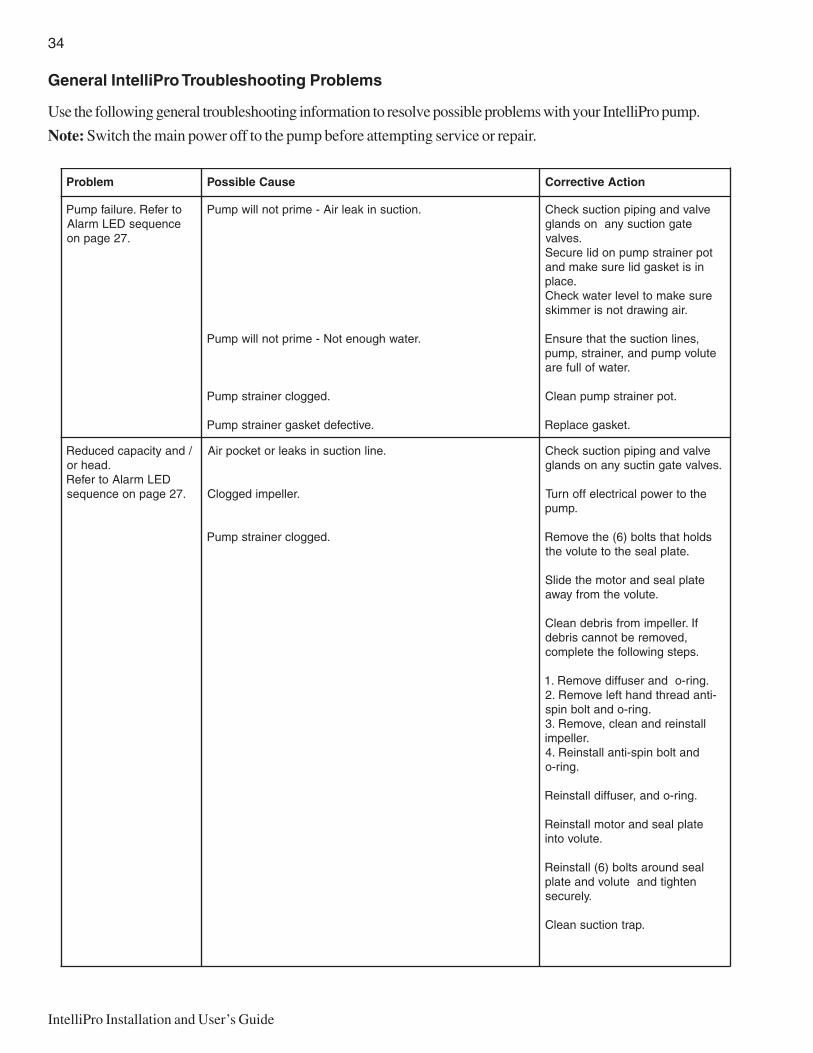
General IntelliPro Troubleshooting Problems
Use the following general troubleshooting information to resolve possible problems with your IntelliPro pump.
Note: Switch the main power off to the pump before attempting service or repair.
melborP esuaCelbissoP noitcAevitcerroC
otrefeR.eruliafpmuPecneuqesDELmralA
.72egapno
.noitcusnikaelriA-emirptonlliwpmuP
.retawhguonetoN-emirptonlliwpmuP
.deggolcreniartspmuP
.evitcefedteksagreniartspmuP
evlavdnagnipipnoitcuskcehCetagnoitcusynanosdnalg
.sevlavtopreniartspmupnodileruceS
nisiteksagdilerusekamdna.ecalp
erusekamotlevelretawkcehC.riagniwardtonsiremmiks
,senilnoitcusehttahterusnEetulovpmupdna,reniarts,pmup
.retawfollufera
.topreniartspmupnaelC
.teksagecalpeR
/dnayticapacdecudeR.daehro
DELmralAotrefeR.72egapnoecneuqes
.enilnoitcusniskaelrotekcopriA
.rellepmideggolC
.deggolcreniartspmuP
evlavdnagnipipnoitcuskcehC.sevlavetagnitcusynanosdnalg
ehtotrewoplacirtceleffonruT.pmup
sdlohtahtstlob)6(ehtevomeR.etalplaesehtotetuloveht
etalplaesdnarotomehtedilS.etulovehtmorfyawa
fI.rellepmimorfsirbednaelC,devomerebtonnacsirbed
.spetsgniwollofehtetelpmoc
.gnir-odnaresuffidevomeR.1-itnadaerhtdnahtfelevomeR.2
.gnir-odnatlobnipsllatsnierdnanaelc,evomeR.3
.rellepmidnatlobnips-itnallatsnieR.4
.gnir-o
.gnir-odna,resuffidllatsnieR
etalplaesdnarotomllatsnieR.etulovotni
laesdnuorastlob)6(llatsnieRnethgitdnaetulovdnaetalp
.yleruces
.partnoitcusnaelC
35
IntelliPro Installation and User’s Guide
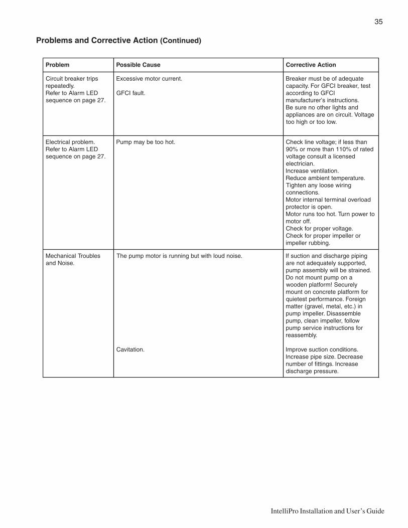
Problems and Corrective Action (Continued)
melborP esuaCelbissoP noitcAevitcerroC
spirtrekaerbtiucriC.yldetaeper
DELmralAotrefeR.72egapnoecneuqes
.tnerrucrotomevissecxE
.tluafICFG
etauqedafoebtsumrekaerBtset,rekaerbICFGroF.yticapac
ICFGotgnidrocca.snoitcurtsnis’rerutcafunam
dnasthgilrehtooneruseBegatloV.tiucricnoerasecnailppa
.wolootrohgihoot
.melborplacirtcelEDELmralAotrefeR
.72egapnoecneuqes
.tohootebyampmuP nahtsselfi;egatlovenilkcehCdetarfo%011nahteromro%09
desnecilatlusnocegatlov.naicirtcele
.noitalitnevesaercnI.erutarepmettneibmaecudeR
gniriwesoolynanethgiT.snoitcennoc
daolrevolanimretlanretnirotoM.neposirotcetorp
otrewopnruT.tohootsnurrotoM.fforotom
.egatlovreporprofkcehCrorellepmireporprofkcehC
.gnibburrellepmi
selbuorTlacinahceM.esioNdna
.esionduolhtiwtubgninnursirotompmupehT
.noitativaC
gnipipegrahcsiddnanoitcusfI,detroppusyletauqedatonera
.deniartseblliwylbmessapmupanopmuptnuomtonoD
yleruceS!mroftalpnedoowrofmroftalpetercnocnotnuom
ngieroF.ecnamrofreptseteiuqni).cte,latem,levarg(rettamelbmessasiD.rellepmipmup
wollof,rellepminaelc,pmuprofsnoitcurtsniecivrespmup
.ylbmessaer
.snoitidnocnoitcusevorpmIesaerceD.ezisepipesaercnI
esaercnI.sgnittifforebmun.erusserpegrahcsid

P/N 357291 - Rev A