Embed Size (px)
Citation preview

Installation andOperations Manual
Addressable Fire Alarm Control Panel
Document: 151274-L8
Rev: XP/N 151274-L8:X ECN: 17-0298
INTELLIKNIGHT®
Model 5808

2
Fire Alarm & Emergency Communication System LimitationsWhile a life safety system may lower insurance rates, it is not a substitute for life and property insurance!An automatic fire alarm system—typically made up of smoke detectors, heat detectors, manual pull stations, audible warning devices, and a fire alarm control panel (FACP) with remote notifi-cation capability—can provide early warning of a developing fire. Such a system, however, does not assure protection against property damage or loss of life resulting from a fire. An emergency communication system—typically made up of an automatic fire alarm system (as described above) and a life safety communication system that may include an autonomous control unit (ACU), local operating console (LOC), voice commu-nication, and other various inter-operable communication meth-ods—can broadcast a mass notification message. Such a system, however, does not assure protection against property damage or loss of life resulting from a fire or life safety event.The Manufacturer recommends that smoke and/or heat detectors be located throughout a protected premises following the recommendations of the current edition of the National Fire Protection Association Standard 72 (NFPA 72), manufacturer's recommendations, State and local codes, and the recommendations contained in the Guide for Proper Use of System Smoke Detectors, which is made available at no charge to all installing dealers. This document can be found at http://www.systemsensor.com/appguides/. A study by the Federal Emergency Management Agency (an agency of the United States government) indicated that smoke detectors may not go off in as many as 35% of all fires. While fire alarm systems are designed to provide early warning against fire, they do not guarantee warning or protection against fire. A fire alarm system may not provide timely or adequate warning, or simply may not function, for a variety of reasons: Smoke detectors may not sense fire where smoke cannot reach the detectors such as in chimneys, in or behind walls, on roofs, or on the other side of closed doors. Smoke detectors also may not sense a fire on another level or floor of a building. A second-floor detector, for example, may not sense a first-floor or basement fire. Particles of combustion or “smoke” from a developing fire may not reach the sensing chambers of smoke detectors because:• Barriers such as closed or partially closed doors, walls, chim-
neys, even wet or humid areas may inhibit particle or smoke flow.
• Smoke particles may become “cold,” stratify, and not reach the ceiling or upper walls where detectors are located.
• Smoke particles may be blown away from detectors by air out-lets, such as air conditioning vents.
• Smoke particles may be drawn into air returns before reaching the detector.
The amount of “smoke” present may be insufficient to alarm smoke detectors. Smoke detectors are designed to alarm at vari-ous levels of smoke density. If such density levels are not created by a developing fire at the location of detectors, the detectors will not go into alarm.Smoke detectors, even when working properly, have sensing lim-itations. Detectors that have photoelectronic sensing chambers tend to detect smoldering fires better than flaming fires, which have little visible smoke. Detectors that have ionizing-type sens-ing chambers tend to detect fast-flaming fires better than smolder-ing fires. Because fires develop in different ways and are often unpredictable in their growth, neither type of detector is necessar-ily best and a given type of detector may not provide adequate warning of a fire. Smoke detectors cannot be expected to provide adequate warn-ing of fires caused by arson, children playing with matches (espe-cially in bedrooms), smoking in bed, and violent explosions (caused by escaping gas, improper storage of flammable materi-als, etc.).
Heat detectors do not sense particles of combustion and alarm only when heat on their sensors increases at a predetermined rate or reaches a predetermined level. Rate-of-rise heat detectors may be subject to reduced sensitivity over time. For this reason, the rate-of-rise feature of each detector should be tested at least once per year by a qualified fire protection specialist. Heat detec-tors are designed to protect property, not life. IMPORTANT! Smoke detectors must be installed in the same room as the control panel and in rooms used by the system for the connection of alarm transmission wiring, communications, sig-naling, and/or power. If detectors are not so located, a developing fire may damage the alarm system, compromising its ability to report a fire. Audible warning devices such as bells, horns, strobes, speakers and displays may not alert people if these devices are located on the other side of closed or partly open doors or are located on another floor of a building. Any warning device may fail to alert people with a disability or those who have recently con-sumed drugs, alcohol, or medication. Please note that:• An emergency communication system may take priority over a
fire alarm system in the event of a life safety emergency.• Voice messaging systems must be designed to meet intelligi-
bility requirements as defined by NFPA, local codes, and Authorities Having Jurisdiction (AHJ).
• Language and instructional requirements must be clearly dis-seminated on any local displays.
• Strobes can, under certain circumstances, cause seizures in people with conditions such as epilepsy.
• Studies have shown that certain people, even when they hear a fire alarm signal, do not respond to or comprehend the meaning of the signal. Audible devices, such as horns and bells, can have different tonal patterns and frequencies. It is the property owner's responsibility to conduct fire drills and other training exercises to make people aware of fire alarm signals and instruct them on the proper reaction to alarm sig-nals.
• In rare instances, the sounding of a warning device can cause temporary or permanent hearing loss.
A life safety system will not operate without any electrical power. If AC power fails, the system will operate from standby batteries only for a specified time and only if the batteries have been prop-erly maintained and replaced regularly. Equipment used in the system may not be technically compati-ble with the control panel. It is essential to use only equipment listed for service with your control panel. Telephone lines needed to transmit alarm signals from a prem-ises to a central monitoring station may be out of service or tem-porarily disabled. For added protection against telephone line failure, backup radio transmission systems are recommended. The most common cause of life safety system malfunction is inadequate maintenance. To keep the entire life safety system in excellent working order, ongoing maintenance is required per the manufacturer's recommendations, and UL and NFPA standards. At a minimum, the requirements of NFPA 72 shall be followed. Environments with large amounts of dust, dirt, or high air velocity require more frequent maintenance. A maintenance agreement should be arranged through the local manufacturer's representa-tive. Maintenance should be scheduled monthly or as required by National and/or local fire codes and should be performed by authorized professional life safety system installers only. Ade-quate written records of all inspections should be kept.
Limit-D-1-2013

3
Installation PrecautionsAdherence to the following will aid in problem-free installation with long-term reliability:WARNING - Several different sources of power can be connected to the fire alarm control panel. Disconnect all sources of power before servicing. Control unit and associated equipment may be damaged by removing and/or inserting cards, modules, or interconnecting cables while the unit is energized. Do not attempt to install, service, or operate this unit until manuals are read and understood.
CAUTION - System Re-acceptance Test after Software Changes: To ensure proper system operation, this product must be tested in accordance with NFPA 72 after any pro-gramming operation or change in site-specific software. Re-acceptance testing is required after any change, addition or deletion of system components, or after any modification, repair or adjustment to system hardware or wiring. All compo-nents, circuits, system operations, or software functions known to be affected by a change must be 100% tested. In addition, to ensure that other operations are not inadvertently affected, at least 10% of initiating devices that are not directly affected by the change, up to a maximum of 50 devices, must also be tested and proper system operation verified.
This system meets NFPA requirements for operation at 0-49º C/32-120º F and at a relative humidity. However, the useful life of the system's standby batteries and the electronic com-ponents may be adversely affected by extreme temperature ranges and humidity. Therefore, it is recommended that this system and its peripherals be installed in an environment with a normal room temperature of 15-27º C/60-80º F.
Verify that wire sizes are adequate for all initiating and indi-cating device loops. Most devices cannot tolerate more than a 10% I.R. drop from the specified device voltage.
Like all solid state electronic devices, this system may operate erratically or can be damaged when subjected to light-ning induced transients. Although no system is completely immune from lightning transients and interference, proper grounding will reduce susceptibility. Overhead or outside aerial wiring is not recommended, due to an increased sus-ceptibility to nearby lightning strikes. Consult with the Techni-cal Services Department if any problems are anticipated or encountered.
Disconnect AC power and batteries prior to removing or inserting circuit boards. Failure to do so can damage circuits.
Remove all electronic assemblies prior to any drilling, filing, reaming, or punching of the enclosure. When possible, make all cable entries from the sides or rear. Before making modifi-cations, verify that they will not interfere with battery, trans-former, or printed circuit board location.
Do not tighten screw terminals more than 9 in-lbs. Over-tightening may damage threads, resulting in reduced terminal contact pressure and difficulty with screw terminal removal.
This system contains static-sensitive components. Always ground yourself with a proper wrist strap before handling any circuits so that static charges are removed from the body. Use static suppressive packaging to protect electronic assemblies removed from the unit.
Follow the instructions in the installation, operating, and programming manuals. These instructions must be followed to avoid damage to the control panel and associated equipment. FACP operation and reliability depend upon proper installa-tion.
Precau-D1-9-2005

4
Documentation FeedbackYour feedback helps us keep our documentation up-to-date and accurate. If you have a question or encounter a problem not covered in this manual, contact Silent Knight Technical Support at 800-446-6444.
Please give the following information:
•Product name and version number (if applicable)
•Printed manual
•Topic Title
•Page number (for printed manual)
•Brief description of content you think should be improved or corrected
•Your suggestion for how to correct/improve documentation
To order parts, contact Silent Knight Sales at 800-328-0103.
Contents
1
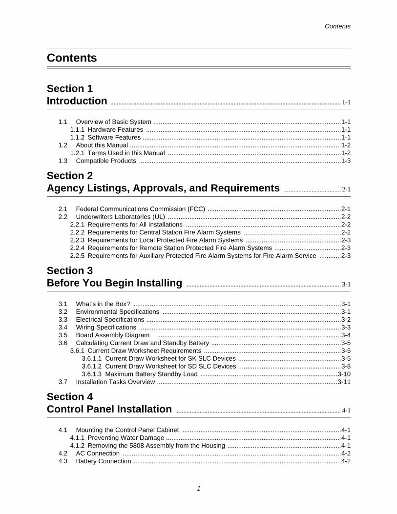
Contents
Section 1Introduction .............................................................................................................................................. 1-1
1.1 Overview of Basic System ........................................................................................................1-11.1.1 Hardware Features ............................................................................................................1-11.1.2 Software Features ..............................................................................................................1-1
1.2 About this Manual .....................................................................................................................1-21.2.1 Terms Used in this Manual ................................................................................................1-2
1.3 Compatible Products ................................................................................................................1-3
Section 2Agency Listings, Approvals, and Requirements ................................... 2-1
2.1 Federal Communications Commission (FCC) ..........................................................................2-12.2 Underwriters Laboratories (UL) ................................................................................................2-2
2.2.1 Requirements for All Installations ......................................................................................2-22.2.2 Requirements for Central Station Fire Alarm Systems ......................................................2-22.2.3 Requirements for Local Protected Fire Alarm Systems .....................................................2-32.2.4 Requirements for Remote Station Protected Fire Alarm Systems .....................................2-32.2.5 Requirements for Auxiliary Protected Fire Alarm Systems for Fire Alarm Service ............2-3
Section 3Before You Begin Installing ............................................................................................... 3-1
3.1 What’s in the Box? ...................................................................................................................3-13.2 Environmental Specifications ...................................................................................................3-13.3 Electrical Specifications ............................................................................................................3-23.4 Wiring Specifications ................................................................................................................3-33.5 Board Assembly Diagram ......................................................................................................3-43.6 Calculating Current Draw and Standby Battery ........................................................................3-5
3.6.1 Current Draw Worksheet Requirements ............................................................................3-53.6.1.1 Current Draw Worksheet for SK SLC Devices .........................................................3-53.6.1.2 Current Draw Worksheet for SD SLC Devices .........................................................3-83.6.1.3 Maximum Battery Standby Load ............................................................................3-10
3.7 Installation Tasks Overview ....................................................................................................3-11
Section 4Control Panel Installation ...................................................................................................... 4-1
4.1 Mounting the Control Panel Cabinet ........................................................................................4-14.1.1 Preventing Water Damage .................................................................................................4-14.1.2 Removing the 5808 Assembly from the Housing ...............................................................4-1
4.2 AC Connection .........................................................................................................................4-24.3 Battery Connection ...................................................................................................................4-2
Contents
2
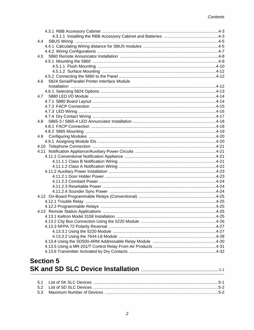
4.3.1 RBB Accessory Cabinet .....................................................................................................4-34.3.1.1 Installing the RBB Accessory Cabinet and Batteries ...............................................4-3
4.4 SBUS Wiring ............................................................................................................................4-54.4.1 Calculating Wiring distance for SBUS modules .................................................................4-54.4.2 Wiring Configurations .........................................................................................................4-7
4.5 5860 Remote Annunciator Installation .....................................................................................4-84.5.1 Mounting the 5860 .............................................................................................................4-9
4.5.1.1 Flush Mounting .......................................................................................................4-104.5.1.2 Surface Mounting ...................................................................................................4-12
4.5.2 Connecting the 5860 to the Panel ....................................................................................4-124.6 5824 Serial/Parallel Printer Interface Module
Installation ..............................................................................................................................4-124.6.1 Selecting 5824 Options ....................................................................................................4-13
4.7 5880 LED I/O Module .............................................................................................................4-144.7.1 5880 Board Layout ...........................................................................................................4-144.7.2 FACP Connection ............................................................................................................4-154.7.3 LED Wiring .......................................................................................................................4-164.7.4 Dry Contact Wiring ...........................................................................................................4-17
4.8 5865-3 / 5865-4 LED Annunciator Installation ........................................................................4-184.8.1 FACP Connection ............................................................................................................4-184.8.2 5865 Mounting .................................................................................................................4-19
4.9 Configuring Modules ..............................................................................................................4-204.9.1 Assigning Module IDs ......................................................................................................4-20
4.10 Telephone Connection ...........................................................................................................4-214.11 Notification Appliance/Auxiliary Power Circuits ......................................................................4-21
4.11.1 Conventional Notification Appliance ...............................................................................4-214.11.1.1 Class B Notification Wiring ....................................................................................4-214.11.1.2 Class A Notification Wiring ....................................................................................4-22
4.11.2 Auxiliary Power Installation .............................................................................................4-234.11.2.1 Door Holder Power ................................................................................................4-234.11.2.2 Constant Power .....................................................................................................4-244.11.2.3 Resettable Power ..................................................................................................4-244.11.2.4 Sounder Sync Power ............................................................................................4-24
4.12 On-Board Programmable Relays (Conventional) ...................................................................4-254.12.1 Trouble Relay .................................................................................................................4-254.12.2 Programmable Relays ....................................................................................................4-25
4.13 Remote Station Applications ..................................................................................................4-254.13.1 Keltron Model 3158 Installation ......................................................................................4-254.13.2 City Box Connection Using the 5220 Module .................................................................4-264.13.3 NFPA 72 Polarity Reversal .............................................................................................4-27
4.13.3.1 Using the 5220 Module .........................................................................................4-274.13.3.2 Using the 7644-L8 Module ....................................................................................4-28
4.13.4 Using the SD500-ARM Addressable Relay Module .......................................................4-304.13.5 Using a MR-201/T Control Relay From Air Products ......................................................4-314.13.6 Transmitter Activated by Dry Contacts ...........................................................................4-32
Section 5SK and SD SLC Device Installation .......................................................................... 5-1
5.1 List of SK SLC Devices ............................................................................................................5-15.2 List of SD SLC Devices ............................................................................................................5-25.3 Maximum Number of Devices ..................................................................................................5-2
Contents
3
5.4 Wiring Requirements for SLC Devices .....................................................................................5-25.4.1 Wiring SLC in Style 4 (Class B) Configuration ...................................................................5-25.4.2 Wiring SLC in Style 6 & 7 (Class A) Configuration ............................................................5-4
5.5 SK Detector Installation ............................................................................................................5-55.5.1 Wiring SK detectors: ..........................................................................................................5-5
5.6 Addressing SK SLC Devices ....................................................................................................5-65.7 SD Detector Installation ............................................................................................................5-6
5.7.1 Wiring SD Detectors ..........................................................................................................5-65.8 Addressing SD Devices ............................................................................................................5-7
5.8.1 SD505-PHOTO or SD505-HEAT .......................................................................................5-75.8.2 SLC Devices with DIP Switches ........................................................................................5-8
Section 6Programming Overview ........................................................................................................... 6-1
6.1 JumpStart Autoprogramming ...................................................................................................6-16.1.1 Input Points ........................................................................................................................6-16.1.2 Output Points .....................................................................................................................6-16.1.3 Running JumpStart AutoProgramming ..............................................................................6-2
6.2 Mapping Overview ....................................................................................................................6-46.2.1 Input Point Mapping ...........................................................................................................6-56.2.2 Output Circuit Mapping ......................................................................................................6-66.2.3 Zone Event Mapping ..........................................................................................................6-76.2.4 Mapping LED Points ..........................................................................................................6-9
6.3 Programming Using the 5660 Silent Knight Software Suite ...................................................6-106.4 Programming Using an Annunciator ......................................................................................6-10
6.4.1 Entering / Exiting the Programming Menu .......................................................................6-106.4.2 Moving through the Menus ..............................................................................................6-116.4.3 Selecting Options and Entering Data ...............................................................................6-116.4.4 Editing Keys .....................................................................................................................6-11
6.5 Programming Menu Quick Reference ....................................................................................6-12
Section 7Programming ......................................................................................................................................... 7-1
7.1 UL 864 Programming Requirements ........................................................................................7-17.2 Modules ....................................................................................................................................7-1
7.2.1 Edit Modules ......................................................................................................................7-27.2.1.1 Naming Modules ......................................................................................................7-27.2.1.2 Module, Wiring Class ...............................................................................................7-2
7.2.2 Adding a Module ................................................................................................................7-27.2.3 Deleting a Module ..............................................................................................................7-37.2.4 View Module List ................................................................................................................7-3
7.3 Zone .........................................................................................................................................7-37.3.1 Edit Zone ............................................................................................................................7-3
7.3.1.1 Edit Zone Name .......................................................................................................7-47.3.1.2 Edit Zone Properties ................................................................................................7-47.3.1.3 Zone Outputs ...........................................................................................................7-67.3.1.4 Cadence Patterns ....................................................................................................7-87.3.1.5 Zone Accessory Options ..........................................................................................7-9
7.3.2 Add Zone ...........................................................................................................................7-9

Model 5808 Installation Manual
4
7.3.3 Delete Zone .......................................................................................................................7-97.3.4 View Zone Points ...............................................................................................................7-9
7.4 Group .....................................................................................................................................7-107.4.1 Edit Group ........................................................................................................................7-10
7.4.1.1 Edit Group Name ...................................................................................................7-107.4.1.2 Edit Group Properties .............................................................................................7-10
7.4.2 Add Group ........................................................................................................................7-127.4.3 Delete Group ....................................................................................................................7-127.4.4 View Group Points ...........................................................................................................7-137.4.5 Edit Output Group Templates ..........................................................................................7-13
7.5 Point .......................................................................................................................................7-147.5.1 Point Programming for the SLC .......................................................................................7-147.5.2 Point Programming For Internal or External Power Module ............................................7-187.5.3 Point Programming For 5880 and 5865 Modules ............................................................7-207.5.4 Assigning a Name to a Point ............................................................................................7-20
7.6 System Options ......................................................................................................................7-217.6.1 Reporting Account ...........................................................................................................7-21
7.6.1.1 Edit Accounts .........................................................................................................7-217.6.1.2 Auto Test Time .......................................................................................................7-23
7.6.2 Phone Lines .....................................................................................................................7-237.6.2.1 Dialing Prefix ..........................................................................................................7-247.6.2.2 Number of Answer Rings .......................................................................................7-247.6.2.3 Dial Option (TouchTone or Pulse) ..........................................................................7-247.6.2.4 Rotary Format ........................................................................................................7-257.6.2.5 Line Monitor ...........................................................................................................7-257.6.2.6 Answering Machine Bypass ...................................................................................7-25
7.6.3 System Event Outputs .....................................................................................................7-257.6.3.1 Trouble Events .......................................................................................................7-257.6.3.2 System Alarm Cadence .........................................................................................7-26
7.6.4 Time Options ....................................................................................................................7-277.6.4.1 Water Flow Delay ...................................................................................................7-277.6.4.2 Alarm Verification Time ..........................................................................................7-277.6.4.3 Low AC Report Delay .............................................................................................7-287.6.4.4 Clock Display Format (AM/PM or Military) .............................................................7-287.6.4.5 Change AC Line Frequency ...................................................................................7-28
7.6.5 Miscellaneous Options .....................................................................................................7-287.6.5.1 Synchronize Strobes Active During Silence ...........................................................7-287.6.5.2 Auto Display Oldest Event .....................................................................................7-297.6.5.3 Report by Zone or by Point ....................................................................................7-297.6.5.4 Plex Door Option ....................................................................................................7-297.6.5.5 Single Key Acknowledge .......................................................................................7-29
7.6.6 Daylight Savings ..............................................................................................................7-297.6.6.1 Automatic Daylight Saving Time Adjustment .........................................................7-297.6.6.2 Daylight Saving Time Start and End ......................................................................7-30
7.6.7 Edit Banner Message .......................................................................................................7-307.6.8 SLC Family ......................................................................................................................7-31
7.7 JumpStart Autoprogramming .................................................................................................7-327.8 Computer Account ..................................................................................................................7-327.9 Access Codes ........................................................................................................................7-32
7.9.1 Profile Edit Menu ..............................................................................................................7-337.9.1.1 Edit Name ..............................................................................................................7-347.9.1.2 Edit Access Code ...................................................................................................7-347.9.1.3 Panel Functions .....................................................................................................7-34
Contents
5
Section 8System Operation ............................................................................................................................ 8-1
8.1 Default User and Installer Codes .............................................................................................8-18.2 Annunciator Description ...........................................................................................................8-1
8.2.1 LCD Displays .....................................................................................................................8-28.2.2 Banner ...............................................................................................................................8-2
8.3 Key Operation ..........................................................................................................................8-28.4 Menu System ...........................................................................................................................8-3
8.4.1 Main Menu Overview .........................................................................................................8-38.4.2 Using the Menus ................................................................................................................8-4
8.5 Basic Operation ........................................................................................................................8-48.5.1 Setting Time and Date .......................................................................................................8-48.5.2 Disable / Enable NACs by Group .......................................................................................8-48.5.3 Disable / Enable a Template ..............................................................................................8-48.5.4 Disable / Enable a Zone .....................................................................................................8-48.5.5 Disable / Enable a Point .....................................................................................................8-48.5.6 View Event History .............................................................................................................8-58.5.7 Clear Event History ............................................................................................................8-58.5.8 Conduct a Fire Drill ............................................................................................................8-58.5.9 Conduct an Indicator Test ..................................................................................................8-58.5.10 Conduct a Walk Test ........................................................................................................8-68.5.11 Conduct a Dialer Test .......................................................................................................8-68.5.12 Silence Alarms or Troubles ..............................................................................................8-68.5.13 Reset Alarms ....................................................................................................................8-68.5.14 Check Detector Sensitivity Through Point Status .............................................................8-78.5.15 View Status of a Point ......................................................................................................8-88.5.16 View Alarms, Supervisories or Troubles ...........................................................................8-88.5.17 View System Information ..................................................................................................8-88.5.18 Reset Items ......................................................................................................................8-8
8.5.18.1 Reset Dialer ............................................................................................................8-88.5.18.2 Reset DSP USB .....................................................................................................8-8
8.5.19 Communicating with a Remote Computer ........................................................................8-88.5.20 Working with a Printer ......................................................................................................8-9
8.6 Operation Mode Behavior ......................................................................................................8-108.7 Releasing Operations .............................................................................................................8-15
8.7.1 Single Interlock Zone Releasing ......................................................................................8-168.7.2 Double Interlock Zone Releasing .....................................................................................8-17
8.8 Smoke Alarm Verification .......................................................................................................8-18
Section 9Reporting ..................................................................................................................................................... 9-1
9.1 Receivers Compatible with the Control Panel ..........................................................................9-19.2 Reporting Formats Table ..........................................................................................................9-1
Section 10Testing and Troubleshooting ......................................................................................... 10-1
10.1 Troubleshooting ......................................................................................................................10-1

Model 5808 Installation Manual
6
10.2 Common Problems .................................................................................................................10-110.2.1 Periodic Testing and Maintenance .................................................................................10-210.2.2 Event History ..................................................................................................................10-3
10.3 Built-in Troubleshooting and Testing Tools ............................................................................10-310.3.1 SLC Device Locator ........................................................................................................10-310.3.2 SLC Multi Locator ...........................................................................................................10-310.3.3 I/O Point Control .............................................................................................................10-4
10.4 Impedances that Cause Earth Ground Faults ........................................................................10-5
Section 11Installation Records .................................................................................................................... 11-1
11.1 SLC Device Point Record .......................................................................................................11-1
Appendix ACompatible Devices ..................................................................................................................... A-1
Appendix BSpecial Characters Lists .........................................................................................................B-1
Silent Knight Fire Product Warranty and Return Policy
Manufacturer Warranties and Limitation of LiabilityModel 5808 Basic Operating Instructions

Contents
7

151274-L8
1-1
Section 1Introduction
The 5808 Fire Alarm Control / Communicator is an addressable fire control system that meets the requirements of UL 864.
1.1 Overview of Basic System
The 5808 base system is an addressable system with a built-in annunciator that can also be used to program the system.
1.1.1 Hardware Features• The 5808 has one signaling line circuit (SLC) that supports 99 SK detectors and 99 SK modules or 127 SD
protocol devices.
• 6.0A of output power is available through 4 sets of terminals for notification appliance circuits or auxiliary applications. Each circuit is power limited per UL 864 and can source up to 3.0A (total output power for all 4 circuits must not exceed 6.0A).
• Built-in dual phone line, digital alarm communicator/transmitter (DACT).
• Reports events to central station by point or by zone.
• UL Listed for pre-action and deluge releasing systems.
• Two general purpose Form C programmable relays.
• One Form C Trouble Relay.
• Basic system operation can be performed using a key or a user code.
• Can be used with up to 12 Model 5860 Remote Annunciators (sold separately).
• Can be used with Model 5865-3, 5865-4, and 5880 in any combination for a total of eight devices on one control panel. See Sections 4.7 and 4.8 for additional information on these models.
• Printing of detector status, event history, and real time event log available through the Model 5824 serial/parallel printer interface module (sold separately).
• 125 software zones, 125 output groups.
• Add four notification/auxiliary power circuits with each 5496 Intelligent Power Module (up to 8 per system).
1.1.2 Software Features
• Advanced smoke detector features:–Automatic drift compensation–Maintenance alert region–Point status meets calibrated smoke test requirements for NFPA 72
• “JumpStart” feature for easy programming
• Non-volatile event history stores 1000 events
• A choice of output patterns available for notification outputs, including ANSI 3.41 temporal signal
• Built-in synchronization appliance support for AMSECO, Faraday, Gentex®, System Sensor®, and
Wheelock®.

IntelliKnight 5808 Installation Manual 151274-L8
1-2
1.2 About this Manual
This manual is intended to be a complete reference for all installation and operation tasks for the 5808. Please let us know if the manual does not meet your needs in any way. We value your feedback!
1.2.1 Terms Used in this Manual
The following terminology is used with the 5808 system:
Table 1-1 Manual Terminology
Term Description
SLC Signaling Line Circuit
Module The term module is used for all hardware devices except for SLC addressable devices and notification appliances. This includes the 5808 panel itself.
Input Point An addressable sensing device, such as a smoke or heat detector or a contact monitor device.
Input Zone A protected area made up of input points.
Output Point(or Output Circuit)
A notification point or circuit for notification appliances. Relay circuits and auxiliary power circuits are also considered output points.
Group (or “Output Group”) A group of output points. Operating characteristics are common to all output points in the group.
Output (or “Cadence”) Pattern The pattern that the output will use, for example, Constant, March Code, ANSI 3.41. Applies to zones and special system events. See Section 7.6.3.2 for additional information.
Mapping Mapping is the process of specifying which outputs are activated when certain events occur in the system. Section 6.2 explains mapping in detail.
Introduction 151274-L8
1-3
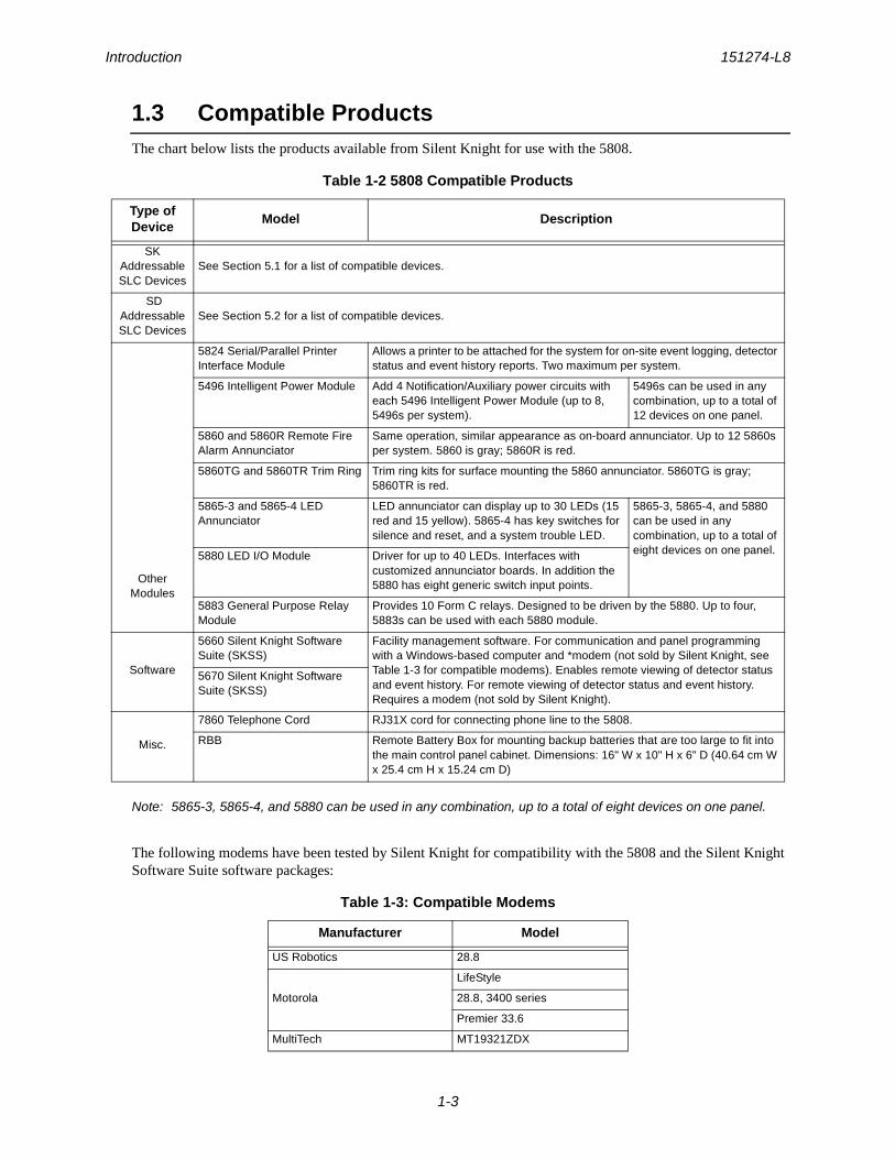
1.3 Compatible ProductsThe chart below lists the products available from Silent Knight for use with the 5808.
Note: 5865-3, 5865-4, and 5880 can be used in any combination, up to a total of eight devices on one panel.
The following modems have been tested by Silent Knight for compatibility with the 5808 and the Silent Knight Software Suite software packages:
Table 1-2 5808 Compatible Products
Type of Device
Model Description
SK Addressable SLC Devices
See Section 5.1 for a list of compatible devices.
SD Addressable SLC Devices
See Section 5.2 for a list of compatible devices.
Other Modules
5824 Serial/Parallel Printer Interface Module
Allows a printer to be attached for the system for on-site event logging, detector status and event history reports. Two maximum per system.
5496 Intelligent Power Module Add 4 Notification/Auxiliary power circuits with each 5496 Intelligent Power Module (up to 8, 5496s per system).
5496s can be used in any combination, up to a total of 12 devices on one panel.
5860 and 5860R Remote Fire Alarm Annunciator
Same operation, similar appearance as on-board annunciator. Up to 12 5860s per system. 5860 is gray; 5860R is red.
5860TG and 5860TR Trim Ring Trim ring kits for surface mounting the 5860 annunciator. 5860TG is gray; 5860TR is red.
5865-3 and 5865-4 LED Annunciator
LED annunciator can display up to 30 LEDs (15 red and 15 yellow). 5865-4 has key switches for silence and reset, and a system trouble LED.
5865-3, 5865-4, and 5880 can be used in any combination, up to a total of eight devices on one panel.5880 LED I/O Module Driver for up to 40 LEDs. Interfaces with
customized annunciator boards. In addition the 5880 has eight generic switch input points.
5883 General Purpose Relay Module
Provides 10 Form C relays. Designed to be driven by the 5880. Up to four, 5883s can be used with each 5880 module.
Software
5660 Silent Knight Software Suite (SKSS)
Facility management software. For communication and panel programming with a Windows-based computer and *modem (not sold by Silent Knight, see Table 1-3 for compatible modems). Enables remote viewing of detector status and event history. For remote viewing of detector status and event history. Requires a modem (not sold by Silent Knight).
5670 Silent Knight Software Suite (SKSS)
Misc.
7860 Telephone Cord RJ31X cord for connecting phone line to the 5808.
RBB Remote Battery Box for mounting backup batteries that are too large to fit into the main control panel cabinet. Dimensions: 16" W x 10" H x 6" D (40.64 cm W x 25.4 cm H x 15.24 cm D)
Table 1-3: Compatible Modems
Manufacturer Model
US Robotics 28.8
Motorola
LifeStyle
28.8, 3400 series
Premier 33.6
MultiTech MT19321ZDX

151274-L8
2-1
Section 2Agency Listings, Approvals, and Requirements
2.1 Federal Communications Commission (FCC)
The following information must be provided to the telephone company before the 5808 can be connected to the phone lines:
This equipment complies with Part 68 of the FCC rules and the requirements adopted by ACTA. On the inside cover of this equipment is a label that contains, among other information, a product identifier. If requested, this information must be provided to the telephone company.
A plug and jack used to connect this equipment to the premises wiring and telephone network must comply with the applicable FCC Part 68 rules and requirements adopted by the ACTA. A compliant telephone cord (not provided) and modular jack must be utilized with this product. It is designed to be used with a modular jack that is also compliant.
The REN (ringer equivalence number) provided on this installation sheet is used to determine the number of devices that may be connected to the public switched telephone network. This number must not exceed 5.0. Since this product has an REN of .8, the number of devices is limited. The REN number is embedded in the FCC registration number as 0.8B.
If the 5808 causes harm to the telephone network, the telephone company will notify you in advance that the temporarily discontinuance of service may be required. But if advance notice is not practical, the telephone company will notify the customer as soon as possible. Also, you will be advised of your right to file a complaint with the FCC if you believe it is necessary.
The telephone company may make changes in its facilities, equipment, operations or procedures that could affect the operation of the equipment. If this happens the telephone company will provide advance notice in order for you to make necessary modifications to maintain uninterrupted service.
If trouble is experienced with the 5808, for repair or warranty information, please contact Silent Knight technical support at 800-446-6444 or www.silentknight.com. If the equipment is causing harm to the telephone network, the telephone company may request that you disconnect the 5808 until the problem has been resolved.
This product cannot be adjusted or repaired in the field. It must be returned to the factory for service.
This equipment is not designed for use with party line service. Connection to party line service is subject to state tariffs. You may contact the state public utility commission, public service commission or corporation commission for information.
Since the 5808 is a commercial fire alarm panel, it must be connected upstream of all other equipment utilizing the phone lines. If you have questions about the installation, contact your telephone company or a qualified
A Manufacturer: Silent Knight by Honeywell
B Model Number: 5808
C FCC registration number: AC6 USA-34758-AL-E
Ringer equivalence: 0.8B
D Type of jack: RJ31X
E Facility Interface Codes: Loop Start: 02LS2
F Service Order Code: 9.0F
Agency Listings, Approvals, and Requirements 151274-L8
2-2
installer.
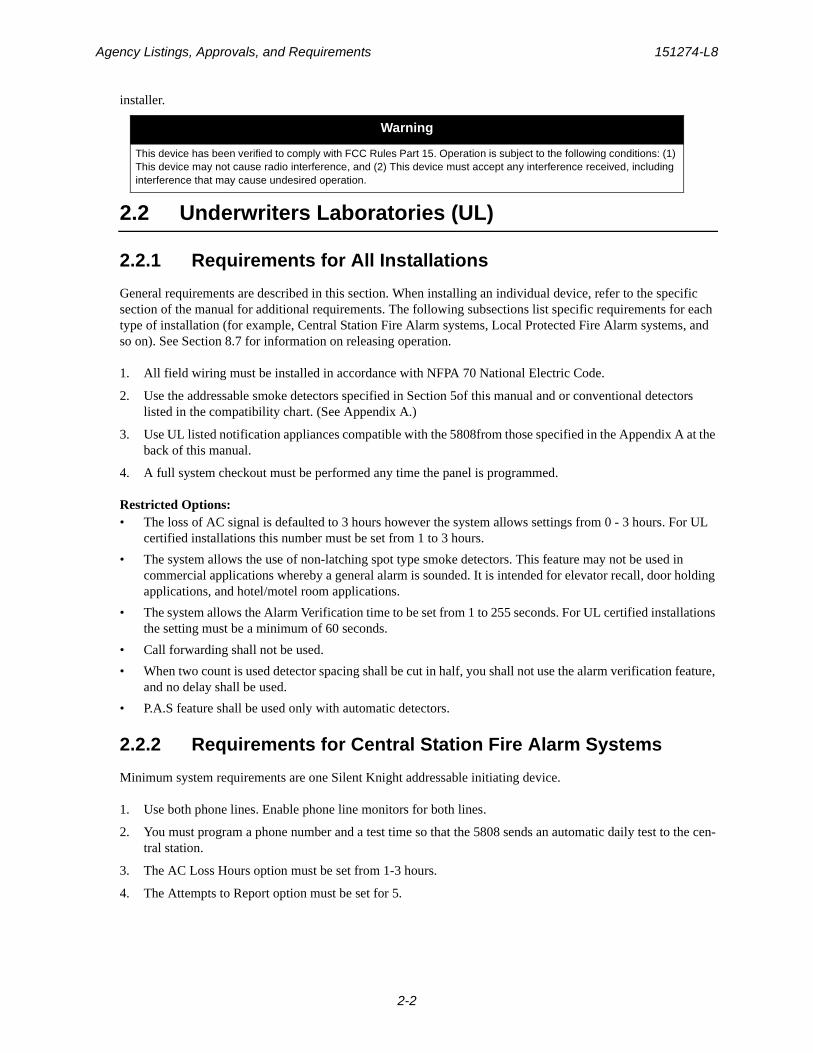
2.2 Underwriters Laboratories (UL)
2.2.1 Requirements for All Installations
General requirements are described in this section. When installing an individual device, refer to the specific section of the manual for additional requirements. The following subsections list specific requirements for each type of installation (for example, Central Station Fire Alarm systems, Local Protected Fire Alarm systems, and so on). See Section 8.7 for information on releasing operation.
1. All field wiring must be installed in accordance with NFPA 70 National Electric Code.
2. Use the addressable smoke detectors specified in Section 5of this manual and or conventional detectors listed in the compatibility chart. (See Appendix A.)
3. Use UL listed notification appliances compatible with the 5808from those specified in the Appendix A at the back of this manual.
4. A full system checkout must be performed any time the panel is programmed.
Restricted Options:• The loss of AC signal is defaulted to 3 hours however the system allows settings from 0 - 3 hours. For UL
certified installations this number must be set from 1 to 3 hours.
• The system allows the use of non-latching spot type smoke detectors. This feature may not be used in commercial applications whereby a general alarm is sounded. It is intended for elevator recall, door holding applications, and hotel/motel room applications.
• The system allows the Alarm Verification time to be set from 1 to 255 seconds. For UL certified installations the setting must be a minimum of 60 seconds.
• Call forwarding shall not be used.
• When two count is used detector spacing shall be cut in half, you shall not use the alarm verification feature, and no delay shall be used.
• P.A.S feature shall be used only with automatic detectors.
2.2.2 Requirements for Central Station Fire Alarm Systems
Minimum system requirements are one Silent Knight addressable initiating device.
1. Use both phone lines. Enable phone line monitors for both lines.
2. You must program a phone number and a test time so that the 5808 sends an automatic daily test to the cen-tral station.
3. The AC Loss Hours option must be set from 1-3 hours.
4. The Attempts to Report option must be set for 5.
Warning
This device has been verified to comply with FCC Rules Part 15. Operation is subject to the following conditions: (1) This device may not cause radio interference, and (2) This device must accept any interference received, including interference that may cause undesired operation.
IntelliKnight 5808 Installation Manual 151274-L8
2-3
2.2.3 Requirements for Local Protected Fire Alarm Systems
At least one UL listed supervised notification appliance must be used. Minimum system requirements are one Silent Knight addressable initiating device.
2.2.4 Requirements for Remote Station Protected Fire Alarm Systems
Minimum system requirements are one Silent Knight addressable initiating device and either a 5220, Keltron 3158 or the built-in Digital Alarm Communicator Transmitter (DACT).
1. Do not exceed the current load restrictions shown in Section 3.6.1.3.
2. The AC Loss Hours option must be set from 1-3 hours.
2.2.5 Requirements for Auxiliary Protected Fire Alarm Systems for Fire Alarm Service
The Model 5220 Direct Connect module must be installed (see Section 4.13.3.1 for wiring).

151274-L8
3-1
Section 3Before You Begin Installing
This section of the manual is intended to help you plan your tasks to facilitate a smooth installation. Please read this section thoroughly, especially if you are installing a 5808 panel for the first time.
3.1 What’s in the Box?
The 5808 ships with the following hardware:
• A cabinet with all hardware assembled
• Two keys for the front door
• Two keys for user operation of the on-board annunciator (installer operations require the Installer’s Code)
• Ten 4.7K ohm end-of-line resistors
• A battery cable for batteries wired in series
3.2 Environmental Specifications
It is important to protect the 5808 control panel from water. To prevent water damage, the following conditions should be FOLLOWED when installing the units:
• Mount indoors in dry locations only
• Do not mount directly on exterior walls, especially masonry walls (condensation)
• Do not mount directly on exterior walls below grade (condensation)
• Protect from plumbing leaks
• Protect from splash caused by sprinkler system inspection ports
• Do not mount in areas with humidity-generating equipment (such as dryers, production machinery)
When selecting a location to mount the 5808 control panel, the unit should be mounted where it will NOT be exposed to temperatures outside the range of 0°C-49°C (32°F-120°F) or humidity not exceeding 93% noncondensing.

Before You Begin Installing 151274-L8
3-2
3.3 Electrical Specifications
Table 3-1 list the terminal block on the 5808 as well as a description of the each individual terminal and their respective electrical rating.
* Regulated/special application when used for releasing.
Table 3-1: Terminal Descriptions and Electrical Specifications
Terminal No.Label
DescriptionRating
Group Individual Voltage Current
Terminal Block 1 AC INPUT B AC input (hot) 120 VAC, 60 Hz 3.6 A
Earth Earth Ground N/A N/A
W AC input (neutral) 120 VAC, 60 Hz 3.6 A
Terminal Block 2 SLC IN – Used for Class A installations 32 VDC 150 mA
+
SLC OUT – SLC terminals 32 VDC 150 mA
+
SLC PROG – Used for programming SLC Detectors
32 VDC 150 mA
+
Terminal Block 3 TELCO 1 RING Phone Line 1 Telco Ring
TIP Phone Line 1 Telco Tip
PHONE 1 RING Phone Line 1 Phone Ring
TIP Phone Line 1 Phone Tip
TELCO 2 RING Phone Line 2 Telco Ring
TIP Phone Line 2 Telco Tip
PHONE 2 RING Phone Line 2 Phone Ring
TIP Phone Line 2 Phone Tip
Terminal Block 4 TROUBLE NC Normally closed relay contact 24 VDC 2.5 A, resistive
COM Common terminal
NO Normally open relay contact
RELAY 1 NC Normally closed relay contact 24 VDC 2.5 A, resistive
COM Common terminal
NO Normally open relay contact
RELAY 2 NC Normally closed relay contact 24 VDC 2.5 A, resistive
COM Common terminal
NO Normally open relay contact
NAC1* – Notification Appliance Circuit/Auxiliary power
24 VDC 3.0 Amp NAC or Aux power +
NAC2* – Notification Appliance Circuit/Auxiliary power
24 VDC 3.0 Amp NAC or Aux power +
NAC3* – Notification Appliance Circuit/Auxiliary power
24 VDC 3.0 Amp NAC or Aux power +
NAC4* – Notification Appliance Circuit/Auxiliary power
24 VDC 3.0 Amp NAC or Aux power +
Terminal Block 5 SBUS B SBUS Communication 5 VDC 100 mA
A
+ SBUS Power 24 VDC 1.0 A
–
BATTERY + To Positive battery terminal 24 VDC Up to 35 Ah (see Section 4.3 for details)– To Negative battery terminal
IntelliKnight 5808 Installation Manual 151274-L8
3-3
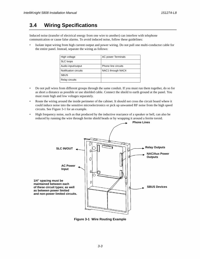
3.4 Wiring Specifications
Induced noise (transfer of electrical energy from one wire to another) can interfere with telephone communication or cause false alarms. To avoid induced noise, follow these guidelines:
• Isolate input wiring from high current output and power wiring. Do not pull one multi-conductor cable for the entire panel. Instead, separate the wiring as follows:
• Do not pull wires from different groups through the same conduit. If you must run them together, do so for as short a distance as possible or use shielded cable. Connect the shield to earth ground at the panel. You must route high and low voltages separately.
• Route the wiring around the inside perimeter of the cabinet. It should not cross the circuit board where it could induce noise into the sensitive microelectronics or pick up unwanted RF noise from the high speed circuits. See Figure 3-1 for an example.
• High frequency noise, such as that produced by the inductive reactance of a speaker or bell, can also be reduced by running the wire through ferrite shield beads or by wrapping it around a ferrite toroid.
Figure 3-1 Wire Routing Example
High voltage AC power Terminals
SLC loops
Audio input/output Phone line circuits
Notification circuits NAC1 through NAC4
SBUS
Relay circuits
Relay Outputs
NAC/Aux PowerOutputs
SBUS Devices
Phone Lines
SLC IN/OUT
AC PowerInput
1/4” spacing must be maintained between each of these circuit types; as well as between power limited and non-power limited circuits.
Before You Begin Installing 151274-L8
3-4
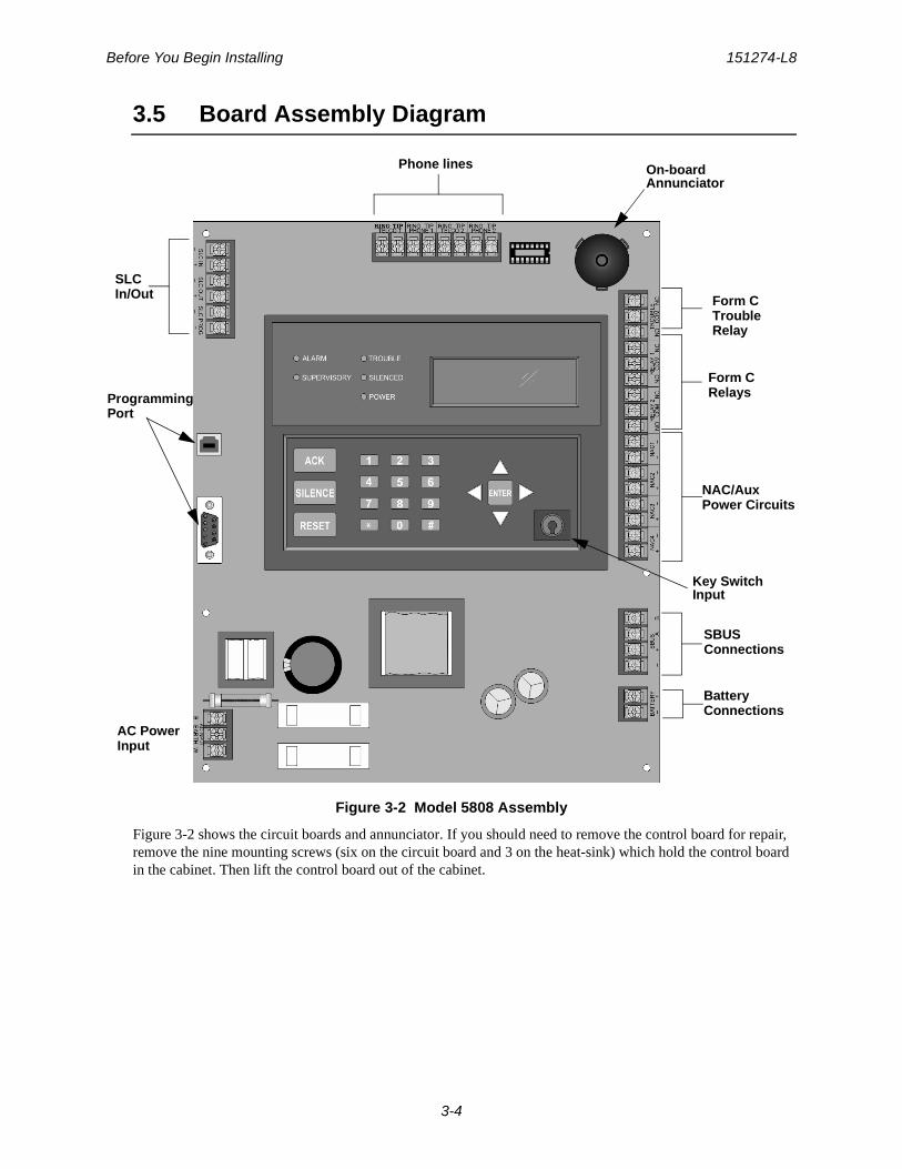
3.5 Board Assembly Diagram
Figure 3-2 Model 5808 Assembly
Figure 3-2 shows the circuit boards and annunciator. If you should need to remove the control board for repair, remove the nine mounting screws (six on the circuit board and 3 on the heat-sink) which hold the control board in the cabinet. Then lift the control board out of the cabinet.
On-board
Key SwitchInput
Annunciator
NAC/AuxPower Circuits
Form CRelays
Phone lines
SLCIn/Out
AC PowerInput
SBUSConnections
BatteryConnections
ProgrammingPort
Form CTroubleRelay

IntelliKnight 5808 Installation Manual 151274-L8
3-5
3.6 Calculating Current Draw and Standby Battery
This section is for helping you determine the current draw and standby battery needs if you are using SK addressable devices (Table 3-2) or SD addressable devices (Table 3-3).
3.6.1 Current Draw Worksheet Requirements
The following steps must be taken when determining 5808 current draw and standby battery requirements.
1. Use the Current Draw Worksheet to determine current draw and standby battery requirements. Use Table 3-2 if installing SK SLC Devices and Table 3-3 if installing SD SLC Devices to determine current draw. For the 5808, the worst case current draw is listed for the panel, addressable devices, and all SBUS expanders. Fill in the number of addressable devices that will be used in the system and compute the current draw requirements for alarm and standby. Record this information in the Current Draw Worksheet on Line A.
2. Add up the current draw for all auxiliary devices and record in the table at Line B.
3. Add up all notification appliance loads and record in the table at Line C.
4. For notification appliance circuits and auxiliary devices not mentioned in the manual, refer to the device manual for the current ratings.
5. Make sure that the total alarm current you calculated, including current for the panel itself, does not exceed 6.0 A. This is the maximum alarm current for the 5808 control panel.
If the current is above 6.0 A you will need to use a notification power expander(s) such as the Silent Knight 5496 intelligent power module, to distribute the power loads so that the 5808 or the power expanders do not exceed their power rating. Refer to the current draw worksheets provided with the 5496 manual so you do not exceed their power requirements.
6. Complete the remaining instructions in the appropriate Current Draw Worksheet for determining battery size requirements.
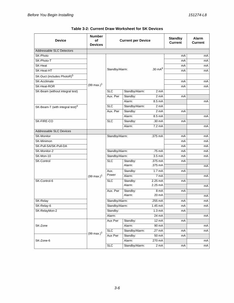
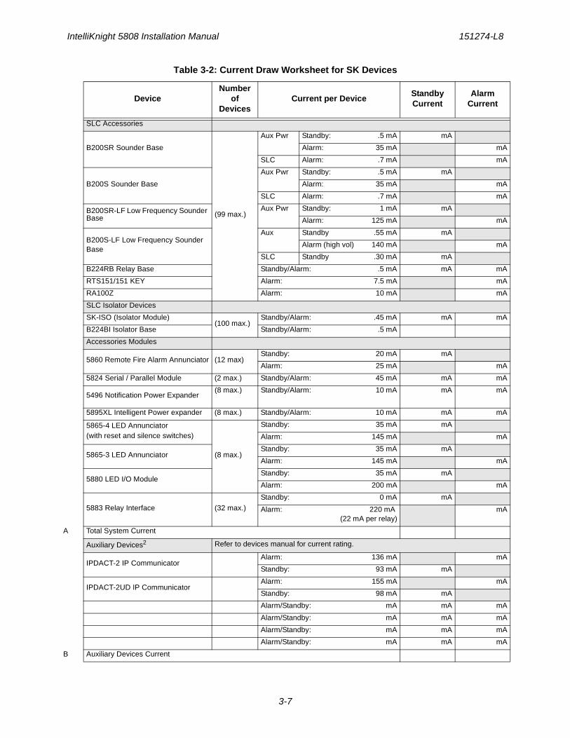
3.6.1.1 Current Draw Worksheet for SK SLC DevicesUse Table 3-2 to determine current requirements during alarm/battery standby operation when SK SLC devices are installed. You can install up to 99 SK detectors and 99 SK modules. (Copy the page if additional space is required.)
Table 3-2: Current Draw Worksheet for SK Devices
DeviceNumber
of Devices
Current per DeviceStandby Current
Alarm Current
For each device use this formula: This column X This column = Current per number of devices.
Fire Panel (Current draw from battery)
1 Standby: 170 mA 170 mA
Alarm: 365 mA 365 mA
Before You Begin Installing 151274-L8
3-6
Addressable SLC Detectors
SK-Photo
(99 max.)1
Standby/Alarm: .30 mA6
mA mA
SK-Photo-T mA mA
SK-Heat mA mA
SK-Heat-HT mA mA
SK-Duct (includes PhotoR)5
SK-Acclimate mA mA
SK-Heat-ROR mA mA
SK-Beam (without integral test) SLC Standby/Alarm: 2 mA
Aux. Pwr Standby: 2 mA mA
Alarm: 8.5 mA mA
SK-Beam-T (with integral test)4 SLC Standby/Alarm: 2 mA
Aux. Pwr Standby: 2 mA mA
Alarm: 8.5 mA mA
SK-FIRE-CO SLC Standby: .30 mA mA
Alarm: 7.2 mA mA
Addressable SLC Devices
SK-Monitor
(99 max.)1
Standby/Alarm: .375 mA mA mA
SK-Minimon mA mA
SK-Pull-SA/SK-Pull-DA mA mA
SK-Monitor-2 Standby/Alarm: .75 mA mA mA
SK-Mon-10 Standby/Alarm: 3.5 mA mA mA
SK-Control SLC Standby: .375 mAAlarm: .375 mA
mA
mA
Aux. Power
Standby: 1.7 mA mA
Alarm: 7 mA mA
SK-Control-6 SLC Standby: 2.25 mAAlarm: 2.25 mA
mA
mA
Aux. Pwr Standby: 8 mAAlarm: 20 mA
mA
mA
SK-Relay Standby/Alarm: .255 mA mA mA
SK-Relay-6 Standby/Alarm: 1.45 mA mA mA
SK-RelayMon-2 Standby: 1.3 mA mA
Alarm: 24 mA mA
SK-Zone
(99 max.)1
Aux Pwr Standby: 12 mA mA
Alarm: 90 mA mA
SLC Standby/Alarm: .27 mA mA mA
SK-Zone-6
Aux Pwr Standby: 50 mA mA
Alarm: 270 mA mA
SLC Standby/Alarm: 2 mA mA mA
Table 3-2: Current Draw Worksheet for SK Devices
DeviceNumber
of Devices
Current per DeviceStandby Current
Alarm Current
IntelliKnight 5808 Installation Manual 151274-L8
3-7
SLC Accessories
B200SR Sounder Base
(99 max.)
Aux Pwr Standby: .5 mA mA
Alarm: 35 mA mA
SLC Alarm: .7 mA mA
B200S Sounder Base
Aux Pwr Standby: .5 mA mA
Alarm: 35 mA mA
SLC Alarm: .7 mA mA
B200SR-LF Low Frequency Sounder Base
Aux Pwr Standby: 1 mA mA
Alarm: 125 mA mA
B200S-LF Low Frequency Sounder Base
Aux Standby .55 mA mA
Alarm (high vol) 140 mA mA
SLC Standby .30 mA mA
B224RB Relay Base Standby/Alarm: .5 mA mA mA
RTS151/151 KEY Alarm: 7.5 mA mA
RA100Z Alarm: 10 mA mA
SLC Isolator Devices
SK-ISO (Isolator Module)(100 max.)
Standby/Alarm: .45 mA mA mA
B224BI Isolator Base Standby/Alarm: .5 mA
Accessories Modules
5860 Remote Fire Alarm Annunciator (12 max)Standby: 20 mA mA
Alarm: 25 mA mA
5824 Serial / Parallel Module (2 max.) Standby/Alarm: 45 mA mA mA
5496 Notification Power Expander(8 max.) Standby/Alarm: 10 mA mA mA
5895XL Intelligent Power expander (8 max.) Standby/Alarm: 10 mA mA mA
5865-4 LED Annunciator(with reset and silence switches)
(8 max.)
Standby: 35 mA mA
Alarm: 145 mA mA
5865-3 LED AnnunciatorStandby: 35 mA mA
Alarm: 145 mA mA
5880 LED I/O ModuleStandby: 35 mA mA
Alarm: 200 mA mA
5883 Relay Interface (32 max.)
Standby: 0 mA mA
Alarm: 220 mA (22 mA per relay)
mA
A Total System Current
Auxiliary Devices2 Refer to devices manual for current rating.
IPDACT-2 IP CommunicatorAlarm: 136 mA mA
Standby: 93 mA mA
IPDACT-2UD IP CommunicatorAlarm: 155 mA mA
Standby: 98 mA mA
Alarm/Standby: mA mA mA
Alarm/Standby: mA mA mA
Alarm/Standby: mA mA mA
Alarm/Standby: mA mA mA
B Auxiliary Devices Current
Table 3-2: Current Draw Worksheet for SK Devices
DeviceNumber
of Devices
Current per DeviceStandby Current
Alarm Current
Before You Begin Installing 151274-L8
3-8
1. Total does not include isolator devices or accessory bases.
2. If using door holders, you do not need to consider door holder current for alarm/battery standby, because power is removed during that time. However, during normal operation, door holders draw current and must be included in the 6.0A total current that can be drawn from the panel.
3. Use next size battery with capacity greater than required.
4. SK-Beam-T draws a maximum of 500mA from Auxiliary power only when the test feature is used. This should be considered when determining auxiliary power capacity but not calculated into current requirements for day to day operation.
5. The SK-Duct housing contains a vacant mount for a SK-Relay (sold separately). Current draw for the SK-Relay is calculated by increasing the SK-Relay row of the calculation sheet by one for each SK-Relay used with a SK-Duct.
6. The FACP can only support 5 devices w/LED’s on. This current draw has been added to the panels alarm current.
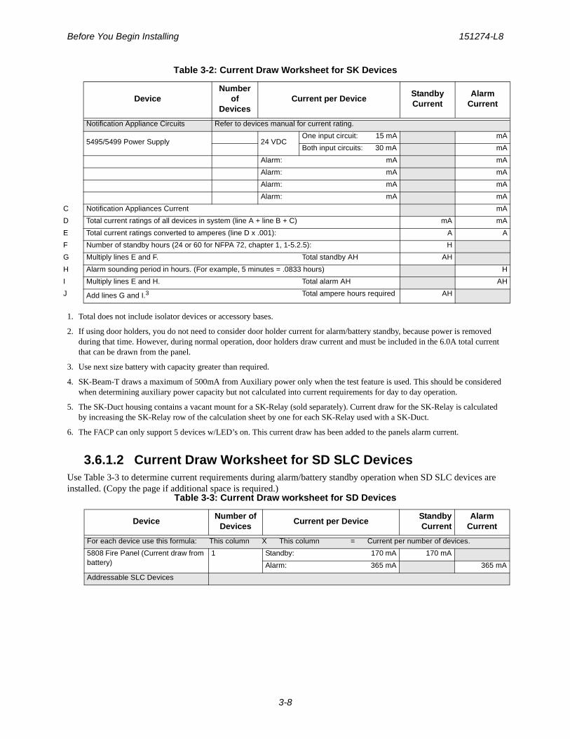
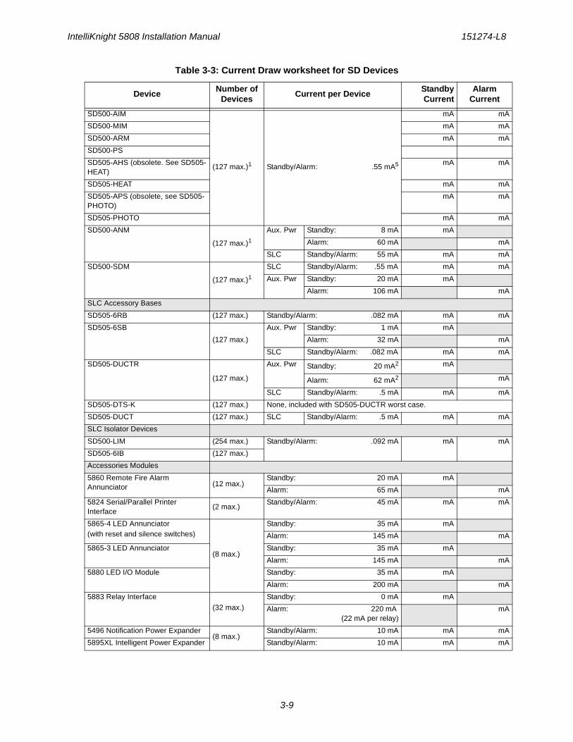
3.6.1.2 Current Draw Worksheet for SD SLC DevicesUse Table 3-3 to determine current requirements during alarm/battery standby operation when SD SLC devices are installed. (Copy the page if additional space is required.)
Notification Appliance Circuits Refer to devices manual for current rating.
5495/5499 Power Supply 24 VDCOne input circuit: 15 mA mA
Both input circuits: 30 mA mA
Alarm: mA mA
Alarm: mA mA
Alarm: mA mA
Alarm: mA mA
C Notification Appliances Current mA
D Total current ratings of all devices in system (line A + line B + C) mA mA
E Total current ratings converted to amperes (line D x .001): A A
F Number of standby hours (24 or 60 for NFPA 72, chapter 1, 1-5.2.5): H
G Multiply lines E and F. Total standby AH AH
H Alarm sounding period in hours. (For example, 5 minutes = .0833 hours) H
I Multiply lines E and H. Total alarm AH AH
J Add lines G and I.3 Total ampere hours required AH
Table 3-3: Current Draw worksheet for SD Devices
DeviceNumber of
DevicesCurrent per Device
StandbyCurrent
Alarm Current
For each device use this formula: This column X This column = Current per number of devices.
5808 Fire Panel (Current draw from battery)
1 Standby: 170 mA 170 mA
Alarm: 365 mA 365 mA
Addressable SLC Devices
Table 3-2: Current Draw Worksheet for SK Devices
DeviceNumber
of Devices
Current per DeviceStandby Current
Alarm Current
IntelliKnight 5808 Installation Manual 151274-L8
3-9
SD500-AIM
(127 max.)1 Standby/Alarm: .55 mA5
mA mA
SD500-MIM mA mA
SD500-ARM mA mA
SD500-PS
SD505-AHS (obsolete. See SD505-HEAT)
mA mA
SD505-HEAT mA mA
SD505-APS (obsolete, see SD505-PHOTO)
mA mA
SD505-PHOTO mA mA
SD500-ANM
(127 max.)1Aux. Pwr Standby: 8 mA mA
Alarm: 60 mA mA
SLC Standby/Alarm: 55 mA mA mA
SD500-SDM
(127 max.)1SLC Standby/Alarm: .55 mA mA mA
Aux. Pwr Standby: 20 mA mA
Alarm: 106 mA mA
SLC Accessory Bases
SD505-6RB (127 max.) Standby/Alarm: .082 mA mA mA
SD505-6SB
(127 max.)
Aux. Pwr Standby: 1 mA mA
Alarm: 32 mA mA
SLC Standby/Alarm: .082 mA mA mA
SD505-DUCTR
(127 max.)
Aux. Pwr Standby: 20 mA2 mA
Alarm: 62 mA2 mA
SLC Standby/Alarm: .5 mA mA mA
SD505-DTS-K (127 max.) None, included with SD505-DUCTR worst case.
SD505-DUCT (127 max.) SLC Standby/Alarm: .5 mA mA mA
SLC Isolator Devices
SD500-LIM (254 max.) Standby/Alarm: .092 mA mA mA
SD505-6IB (127 max.)
Accessories Modules
5860 Remote Fire Alarm Annunciator (12 max.)
Standby: 20 mA mA
Alarm: 65 mA mA
5824 Serial/Parallel Printer Interface
(2 max.)Standby/Alarm: 45 mA mA mA
5865-4 LED Annunciator(with reset and silence switches)
(8 max.)
Standby: 35 mA mA
Alarm: 145 mA mA
5865-3 LED Annunciator Standby: 35 mA mA
Alarm: 145 mA mA
5880 LED I/O Module Standby: 35 mA mA
Alarm: 200 mA mA
5883 Relay Interface
(32 max.)
Standby: 0 mA mA
Alarm: 220 mA (22 mA per relay)
mA
5496 Notification Power Expander(8 max.)
Standby/Alarm: 10 mA mA mA
5895XL Intelligent Power Expander Standby/Alarm: 10 mA mA mA
Table 3-3: Current Draw worksheet for SD Devices
DeviceNumber of
DevicesCurrent per Device
StandbyCurrent
Alarm Current
Before You Begin Installing 151274-L8
3-10
1. Total does not include isolator devices or accessory bases.2. If using 24 VDC aux power only. No standby or alarm current for battery calculation if using 24 VAC, 120
VAC or 240 VAC.3. If using door holders, you do not need to consider door holder current for alarm/battery standby, because
power is removed during that time. However, during normal operation, door holders draw current and must be included in the 6.0A total current that can be drawn from the panel.
4. Use next size battery with capacity greater than required.5. The FACP can only support 5 devices w/LED’s on. This current draw has been added to the panels alarm
current.
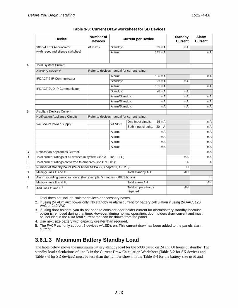
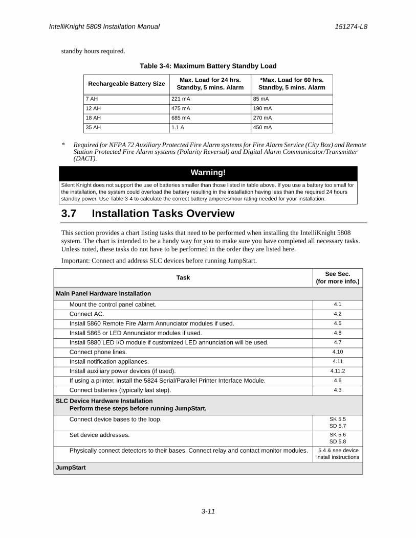
3.6.1.3 Maximum Battery Standby LoadThe table below shows the maximum battery standby load for the 5808 based on 24 and 60 hours of standby. The standby load calculations of line D in the Current Draw Calculation Worksheet (Table 3-2 for SK devices and Table 3-3 for SD devices) must be less than the number shown in the Table 3-4 for the battery size used and
5865-4 LED Annunciator(with reset and silence switches)
(8 max.)
Standby: 35 mA mA
Alarm: 145 mA mA
A Total System Current
Auxiliary Devices3 Refer to devices manual for current rating.
IPDACT-2 IP CommunicatorAlarm: 136 mA mA
Standby: 93 mA mA
IPDACT-2UD IP CommunicatorAlarm: 155 mA mA
Standby: 98 mA mA
Alarm/Standby: mA mA mA
Alarm/Standby: mA mA mA
Alarm/Standby: mA mA mA
B Auxiliary Devices Current
Notification Appliance Circuits Refer to devices manual for current rating.
5495/5499 Power Supply 24 VDCOne input circuit: 15 mA mA
Both input circuits: 30 mA mA
Alarm: mA mA
Alarm: mA mA
Alarm: mA mA
Alarm: mA mA
C Notification Appliances Current mA
D Total current ratings of all devices in system (line A + line B + C) mA mA
E Total current ratings converted to amperes (line D x .001): A A
F Number of standby hours (24 or 60 for NFPA 72, chapter 1, 1-5.2.5): H
G Multiply lines E and F. Total standby AH AH
H Alarm sounding period in hours. (For example, 5 minutes =.0833 hours) H
I Multiply lines E and H. Total alarm AH AH
J Add lines G and I. 4 Total ampere hours required
AH
Table 3-3: Current Draw worksheet for SD Devices
DeviceNumber of
DevicesCurrent per Device
StandbyCurrent
Alarm Current
IntelliKnight 5808 Installation Manual 151274-L8
3-11
standby hours required.
* Required for NFPA 72 Auxiliary Protected Fire Alarm systems for Fire Alarm Service (City Box) and Remote Station Protected Fire Alarm systems (Polarity Reversal) and Digital Alarm Communicator/Transmitter (DACT).
3.7 Installation Tasks Overview
This section provides a chart listing tasks that need to be performed when installing the IntelliKnight 5808 system. The chart is intended to be a handy way for you to make sure you have completed all necessary tasks. Unless noted, these tasks do not have to be performed in the order they are listed here.
Important: Connect and address SLC devices before running JumpStart.
Table 3-4: Maximum Battery Standby Load
Rechargeable Battery SizeMax. Load for 24 hrs.
Standby, 5 mins. Alarm*Max. Load for 60 hrs.
Standby, 5 mins. Alarm
7 AH 221 mA 85 mA
12 AH 475 mA 190 mA
18 AH 685 mA 270 mA
35 AH 1.1 A 450 mA
Warning!Silent Knight does not support the use of batteries smaller than those listed in table above. If you use a battery too small for the installation, the system could overload the battery resulting in the installation having less than the required 24 hours standby power. Use Table 3-4 to calculate the correct battery amperes/hour rating needed for your installation.
TaskSee Sec.
(for more info.)
Main Panel Hardware Installation
Mount the control panel cabinet. 4.1
Connect AC. 4.2
Install 5860 Remote Fire Alarm Annunciator modules if used. 4.5
Install 5865 or LED Annunciator modules if used. 4.8
Install 5880 LED I/O module if customized LED annunciation will be used. 4.7
Connect phone lines. 4.10
Install notification appliances. 4.11
Install auxiliary power devices (if used). 4.11.2
If using a printer, install the 5824 Serial/Parallel Printer Interface Module. 4.6
Connect batteries (typically last step). 4.3
SLC Device Hardware InstallationPerform these steps before running JumpStart.
Connect device bases to the loop. SK 5.5SD 5.7
Set device addresses. SK 5.6SD 5.8
Physically connect detectors to their bases. Connect relay and contact monitor modules. 5.4 & see device install instructions
JumpStart

Before You Begin Installing 151274-L8
3-12
JumpStart is for initial system programming. JumpStart automatically selects some options for SLC devices. See “Input Point Configuration” section of this chart for other options. JumpStart makes selections for the following options. You can customize options, if necessary.
6.1 & 7.7
Device type (detector or switch) configured by JumpStart. To change, see 7.5
Program type of detector (heat, photoelectric, or ionization) selected by JumpStart. To change, see 7.5
System Software Configuration
Select low AC hours report time (3 hours by default). 7.6.4.3
Select Auto Test Time (2:00 AM by default). 7.6.1.2
Enable/disable automatic DST adjustment feature (enabled by default). 7.6.4.4
Change clock display format (12-hour with AM/PM by default). 7.6.4.4
Set up reporting accounts. 7.6.1
Select options for phone lines. 7.6.2
Select system-wide response to trouble conditions, if desired. 7.6.3
Select system-wide cadence patterns for special conditions (fire drill, Aux1 and Aux2 alarms) if desired.
7.6.3.2
Customize banner message (message that displays on LCD in normal mode) if desired. 7.6.7
Input Point (SLC Device) Configuration
JumpStart automatically selects some options for SLC devices (see “JumpStart” section of this chart). You can change options selected by JumpStart, if necessary and further customize input point options.
Program type of switch (manual pull, fire drill, and so on), if necessary. (JumpStart assigns all switches as Manual Pull type.)
7.5
If the installation includes duct detectors, program detector type. (JumpStart does not distinguish duct detectors from ordinary smoke detectors.)
7.5
Assign a name (or description) to the point. 7.5.4
Assign input points to zones, if necessary. (JumpStart assigns all input points to Zone 1.) 7.5.4
Zone Configuration
Add the zone to the system if it does not already exist. (Zone 1 created by JumpStart.) 7.3.2
Program a name (or description) for the zone. 7.3.1.1
Select alarm delay options (detection characteristics) for zone. 7.3.1.1
Select heat detector trip temperature and. (JumpStart selects 150°F for heat detectors and.)
7.3.1.2
Output Point Configuration
Conventional notification circuits (circuits 1-6):
Enable circuits used for notification appliances through programming, if necessary. (JumpStart enables circuits 1-6 as Notification.)
7.4.1
Conventional relay circuits (circuits 7-8):
Select options for relay circuits, if desired. Note: Relay circuits will always output continuously (constant pattern), even if assigned to an Output Group that uses a different output pattern.
7.4.1
Auxiliary power circuits (circuits 1-6):
Enable any circuit used for auxiliary power devices through programming. 7.5
Select type of power (door holder, constant, or resettable, or sounder sync) 7.5
Addressable relay modules
Assign addressable relay modules to output groups through programming. (JumpStart assigns all relay modules to Group 1.)
7.5
LED output points (from the 5880 LED I/O module or 5865/66 LED Annunciator)
TaskSee Sec.
(for more info.)

IntelliKnight 5808 Installation Manual 151274-L8
3-13
Assign LED modules to output groups through programming. 7.5.3
All output circuits (1-8):
Disable (set to UNUSED) any unused circuits. If you do not disable unused output circuits, they will cause a trouble condition (unless an EOL resistor is used).
7.5
Select a name for the point, if desired. 7.5.4
Output Group Configuration
Add the group to the system if it does not already exist. 7.4.2
Assign output points to the group. 7.5
Program a name (or description) for the group, if desired. 7.4.1.1
Select “group properties” (see below).
Latching / non-latching 7.4.1.2
Silencing option 7.4.1
Select options for activation with system switches. 7.4.1
Map zones to output groups that will activate when zone goes into alarm. 7.3.1.3
Select a cadence pattern for outputs in the zone. 7.3.1.4
TaskSee Sec.
(for more info.)
151274-L8
4-1
Section 4Control Panel Installation
4.1 Mounting the Control Panel Cabinet
Read the environmental specifications in Section 3.2 before mounting the 5808 panel.
The 5808 cabinet dimensions are:
16" W x 26.4" H x 3.5" D (40.64 cm W x 67.06 cm H x 8.89 cm D).
The 5808 panel should be located within a secured area, where it is accessible to main drop wiring runs and where it can be easily tested and serviced. End-users responsible for maintaining the panel should be able to hear alarms and troubles. When selecting a location, keep in mind that the panel itself is the main source of alarm and trouble annunciation.
When mounting on interior walls, use appropriate screw anchors in plaster. When mounting on concrete, especially when moisture is expected, attach a piece of 3/4 inch plywood to the concrete surface and then attach the 5808 to the plywood. Also mount any other desired components to the plywood.
DO NOT flush-mount the 5808 cabinet in a wall designated as a fire break.
4.1.1 Preventing Water Damage
Water damage to the fire system can be caused by moisture entering the cabinet through the conduits. Conduits that are installed to enter the top of the cabinet are most likely to cause water problems. Installers should take reasonable precautions to prevent water from entering the cabinet. Water damage is not covered under warranty.
4.1.2 Removing the 5808 Assembly from the Housing
If it should ever be necessary to remove the control panel assembly from the cabinet for repair, do so by removing the screws that hold the control panel in to the cabinet. Do not attempt to disassemble the circuit boards.
Caution!To avoid the risk of electrical shock and damage to the unit, power should be OFF at the control panel while installing or servicing.
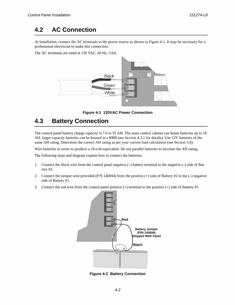
Control Panel Installation 151274-L8
4-2
4.2 AC Connection
At installation, connect the AC terminals to the power source as shown in Figure 4-1. It may be necessary for a professional electrician to make this connection.
The AC terminals are rated at 120 VAC, 60 Hz, 3.6A.
Figure 4-1 120VAC Power Connection
4.3 Battery Connection
The control panel battery charge capacity is 7.0 to 35 AH. The main control cabinet can house batteries up to 18 AH, larger capacity batteries can be housed in a RBB (see Section 4.3.1 for details). Use 12V batteries of the same AH rating. Determine the correct AH rating as per your current load calculation (see Section 3.6).
Wire batteries in series to produce a 24-volt equivalent. Do not parallel batteries to increase the AH rating.
The following steps and diagram explain how to connect the batteries.
1. Connect the black wire from the control panel negative (–) battery terminal to the negative (–) side of Bat-tery #2.
2. Connect the jumper wire provided (P/N 140694) from the positive (+) side of Battery #2 to the (–) negative side of Battery #1.
3. Connect the red wire from the control panel positive (+) terminal to the positive (+) side of Battery #1.
Figure 4-2 Battery Connection
Red
Black
Battery Jumper(P/N 140694)
Shipped With Panel
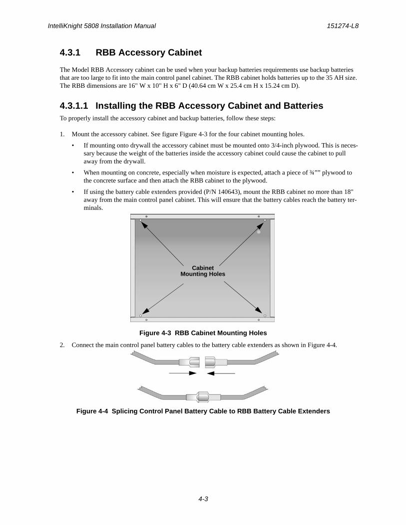
IntelliKnight 5808 Installation Manual 151274-L8
4-3
4.3.1 RBB Accessory Cabinet
The Model RBB Accessory cabinet can be used when your backup batteries requirements use backup batteries that are too large to fit into the main control panel cabinet. The RBB cabinet holds batteries up to the 35 AH size. The RBB dimensions are 16" W x 10" H x 6" D (40.64 cm W x 25.4 cm H x 15.24 cm D).
4.3.1.1 Installing the RBB Accessory Cabinet and BatteriesTo properly install the accessory cabinet and backup batteries, follow these steps:
1. Mount the accessory cabinet. See figure Figure 4-3 for the four cabinet mounting holes.
• If mounting onto drywall the accessory cabinet must be mounted onto 3/4-inch plywood. This is neces-sary because the weight of the batteries inside the accessory cabinet could cause the cabinet to pull away from the drywall.
• When mounting on concrete, especially when moisture is expected, attach a piece of ¾”” plywood to the concrete surface and then attach the RBB cabinet to the plywood.
• If using the battery cable extenders provided (P/N 140643), mount the RBB cabinet no more than 18" away from the main control panel cabinet. This will ensure that the battery cables reach the battery ter-minals.
Figure 4-3 RBB Cabinet Mounting Holes
2. Connect the main control panel battery cables to the battery cable extenders as shown in Figure 4-4.
Figure 4-4 Splicing Control Panel Battery Cable to RBB Battery Cable Extenders
CabinetMounting Holes
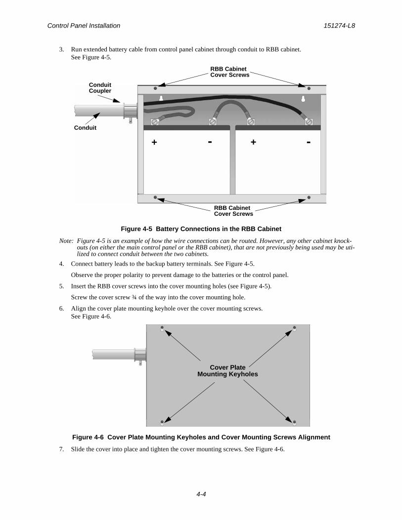
Control Panel Installation 151274-L8
4-4
3. Run extended battery cable from control panel cabinet through conduit to RBB cabinet. See Figure 4-5.
Figure 4-5 Battery Connections in the RBB Cabinet
Note: Figure 4-5 is an example of how the wire connections can be routed. However, any other cabinet knock-outs (on either the main control panel or the RBB cabinet), that are not previously being used may be uti-lized to connect conduit between the two cabinets.
4. Connect battery leads to the backup battery terminals. See Figure 4-5.
Observe the proper polarity to prevent damage to the batteries or the control panel.
5. Insert the RBB cover screws into the cover mounting holes (see Figure 4-5).
Screw the cover screw ¾ of the way into the cover mounting hole.
6. Align the cover plate mounting keyhole over the cover mounting screws. See Figure 4-6.
Figure 4-6 Cover Plate Mounting Keyholes and Cover Mounting Screws Alignment
7. Slide the cover into place and tighten the cover mounting screws. See Figure 4-6.
Conduit
ConduitCoupler
+ +- -
RBB CabinetCover Screws
RBB CabinetCover Screws
Cover PlateMounting Keyholes
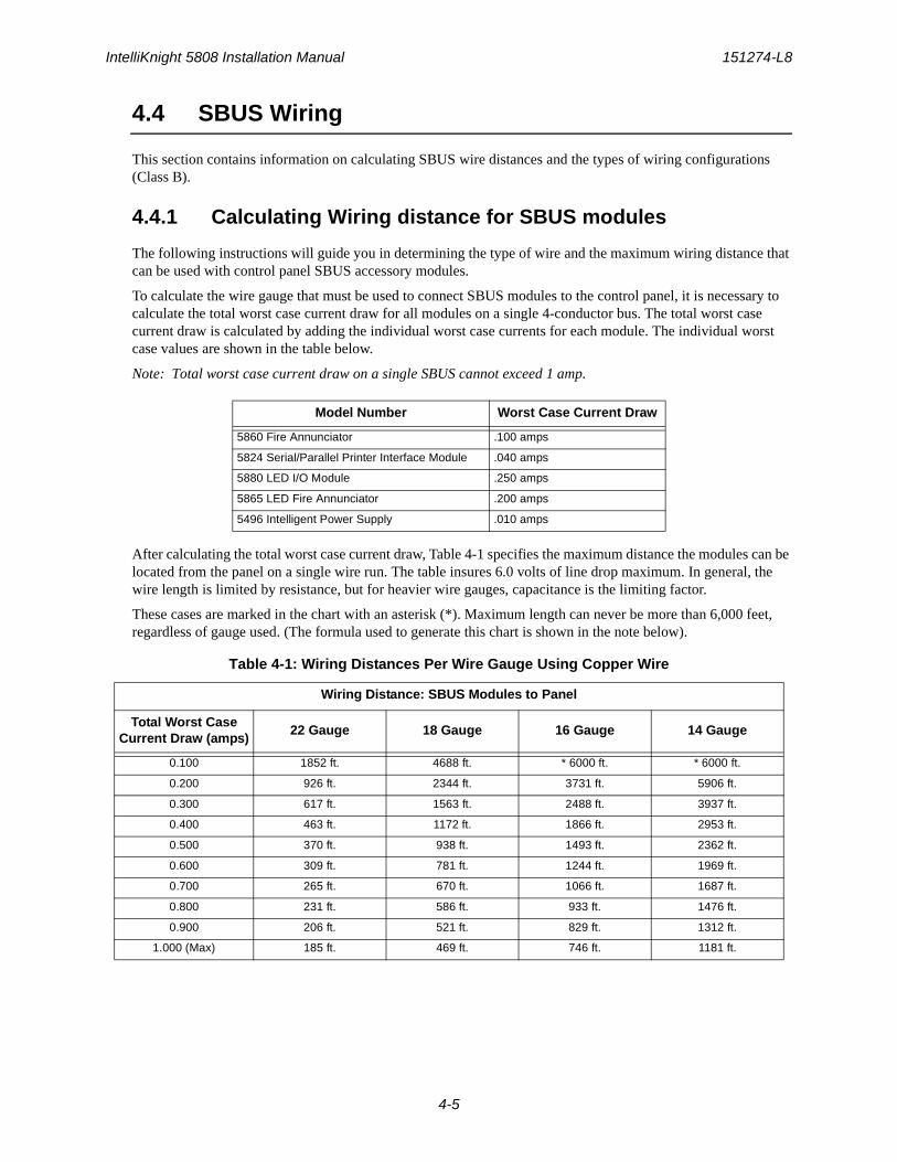
IntelliKnight 5808 Installation Manual 151274-L8
4-5
4.4 SBUS Wiring
This section contains information on calculating SBUS wire distances and the types of wiring configurations (Class B).
4.4.1 Calculating Wiring distance for SBUS modules
The following instructions will guide you in determining the type of wire and the maximum wiring distance that can be used with control panel SBUS accessory modules.
To calculate the wire gauge that must be used to connect SBUS modules to the control panel, it is necessary to calculate the total worst case current draw for all modules on a single 4-conductor bus. The total worst case current draw is calculated by adding the individual worst case currents for each module. The individual worst case values are shown in the table below.
Note: Total worst case current draw on a single SBUS cannot exceed 1 amp.
After calculating the total worst case current draw, Table 4-1 specifies the maximum distance the modules can be located from the panel on a single wire run. The table insures 6.0 volts of line drop maximum. In general, the wire length is limited by resistance, but for heavier wire gauges, capacitance is the limiting factor.
These cases are marked in the chart with an asterisk (*). Maximum length can never be more than 6,000 feet, regardless of gauge used. (The formula used to generate this chart is shown in the note below).
Model Number Worst Case Current Draw
5860 Fire Annunciator .100 amps
5824 Serial/Parallel Printer Interface Module .040 amps
5880 LED I/O Module .250 amps
5865 LED Fire Annunciator .200 amps
5496 Intelligent Power Supply .010 amps
Table 4-1: Wiring Distances Per Wire Gauge Using Copper Wire
Wiring Distance: SBUS Modules to Panel
Total Worst Case Current Draw (amps)
22 Gauge 18 Gauge 16 Gauge 14 Gauge
0.100 1852 ft. 4688 ft. * 6000 ft. * 6000 ft.
0.200 926 ft. 2344 ft. 3731 ft. 5906 ft.
0.300 617 ft. 1563 ft. 2488 ft. 3937 ft.
0.400 463 ft. 1172 ft. 1866 ft. 2953 ft.
0.500 370 ft. 938 ft. 1493 ft. 2362 ft.
0.600 309 ft. 781 ft. 1244 ft. 1969 ft.
0.700 265 ft. 670 ft. 1066 ft. 1687 ft.
0.800 231 ft. 586 ft. 933 ft. 1476 ft.
0.900 206 ft. 521 ft. 829 ft. 1312 ft.
1.000 (Max) 185 ft. 469 ft. 746 ft. 1181 ft.

Control Panel Installation 151274-L8
4-6
Note: The following formulas were used to generate the wire distance chart:
Wiring Distance calculation example:
Suppose a system is configured with the following SBUS modules:
2 - Module 5860 Fire Annunciator
1 - 5496 Notification Power Expander
1 - 5865 LED Fire Annunciator
1 - 5824 Serial/Parallel Printer Interface Module
The total worst case current is calculated as follows:
Using this value, and referring to the Wiring Distance table, it can be found that the available options are:
370 feet maximum using 22 Gauge wire
938 feet maximum using 18 Gauge wire
1493 feet maximum using 16 Gauge wire
2362 feet maximum using 14 Gauge wire
Maximum Resistance (Ohms) =6.0 Volts
Total Worst Case Current Draw (amps)
Maximum Wire Length (Feet) =(6000 feet maximum)
Maximum Resistance (Ohms)* 500
Rpu
where: Rpu = Ohms per 1000 feet for various Wire Gauges (see table below)
Table 4-2: Typical Wire Resistance Per 1000 ft. Using Copper Wire
Wire Gauge Ohms per 1000 feet (Rpu)
22 16.2
18 6.4
16 4.02
14 2.54
5860 Current Draw = 2 x .100 amps = .200 amps
5496 Current Draw = 1 x .010 amps = .010 amps
5865 Current Draw = 1 x .200 amps = .200 amps
5824 Current Draw = 1 x .040 amps = .040 amps
Total Worst Case Current Draw = .450 amps
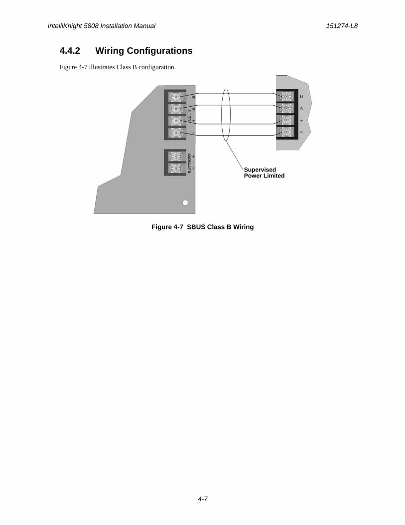
IntelliKnight 5808 Installation Manual 151274-L8
4-7
4.4.2 Wiring Configurations
Figure 4-7 illustrates Class B configuration.
Figure 4-7 SBUS Class B Wiring
SupervisedPower Limited
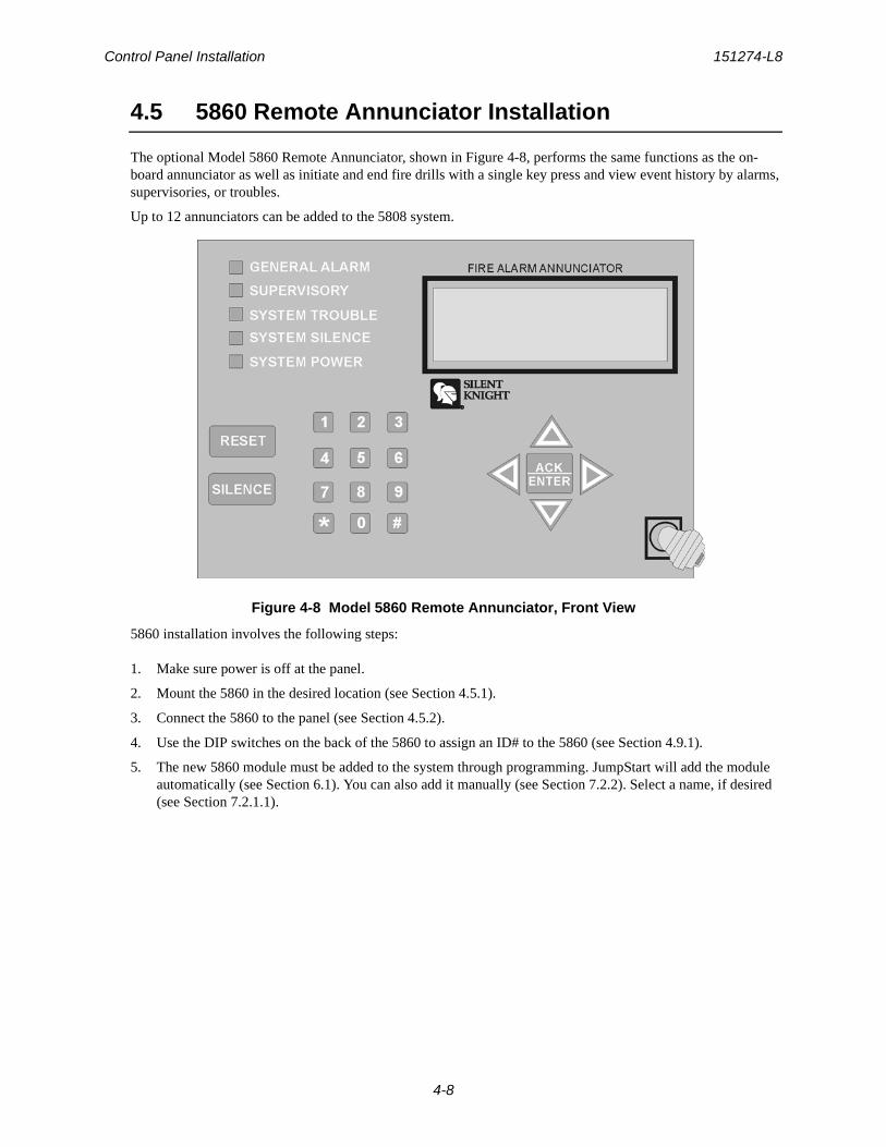
Control Panel Installation 151274-L8
4-8
4.5 5860 Remote Annunciator Installation
The optional Model 5860 Remote Annunciator, shown in Figure 4-8, performs the same functions as the on-board annunciator as well as initiate and end fire drills with a single key press and view event history by alarms, supervisories, or troubles.
Up to 12 annunciators can be added to the 5808 system.
Figure 4-8 Model 5860 Remote Annunciator, Front View
5860 installation involves the following steps:
1. Make sure power is off at the panel.
2. Mount the 5860 in the desired location (see Section 4.5.1).
3. Connect the 5860 to the panel (see Section 4.5.2).
4. Use the DIP switches on the back of the 5860 to assign an ID# to the 5860 (see Section 4.9.1).
5. The new 5860 module must be added to the system through programming. JumpStart will add the module automatically (see Section 6.1). You can also add it manually (see Section 7.2.2). Select a name, if desired (see Section 7.2.1.1).
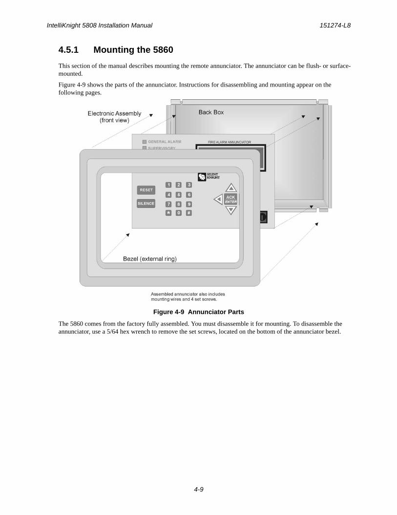
IntelliKnight 5808 Installation Manual 151274-L8
4-9
4.5.1 Mounting the 5860
This section of the manual describes mounting the remote annunciator. The annunciator can be flush- or surface-mounted.
Figure 4-9 shows the parts of the annunciator. Instructions for disassembling and mounting appear on the following pages.
Figure 4-9 Annunciator Parts
The 5860 comes from the factory fully assembled. You must disassemble it for mounting. To disassemble the annunciator, use a 5/64 hex wrench to remove the set screws, located on the bottom of the annunciator bezel.
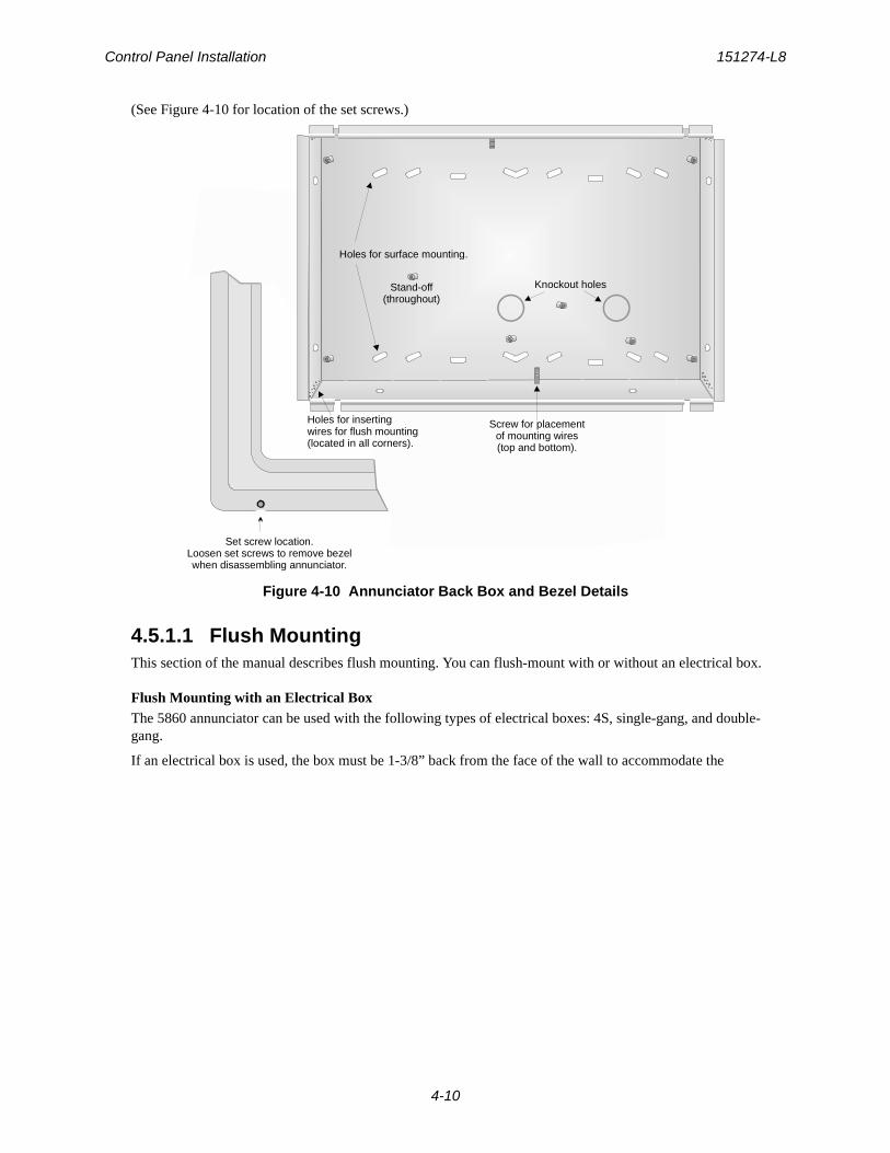
Control Panel Installation 151274-L8
4-10
(See Figure 4-10 for location of the set screws.)
Figure 4-10 Annunciator Back Box and Bezel Details
4.5.1.1 Flush MountingThis section of the manual describes flush mounting. You can flush-mount with or without an electrical box.
Flush Mounting with an Electrical BoxThe 5860 annunciator can be used with the following types of electrical boxes: 4S, single-gang, and double-gang.
If an electrical box is used, the box must be 1-3/8” back from the face of the wall to accommodate the
Set screw location.Loosen set screws to remove bezel when disassembling annunciator.
Knockout holes
Holes for surface mounting.
Holes for insertingwires for flush mounting(located in all corners).
Stand-off(throughout)
Screw for placementof mounting wires(top and bottom).
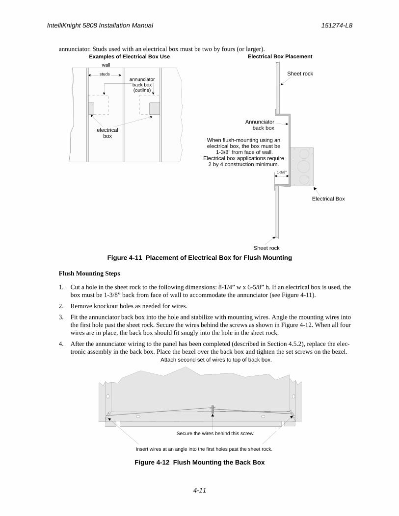
IntelliKnight 5808 Installation Manual 151274-L8
4-11
annunciator. Studs used with an electrical box must be two by fours (or larger).
Figure 4-11 Placement of Electrical Box for Flush Mounting
Flush Mounting Steps
1. Cut a hole in the sheet rock to the following dimensions: 8-1/4” w x 6-5/8” h. If an electrical box is used, the box must be 1-3/8” back from face of wall to accommodate the annunciator (see Figure 4-11).
2. Remove knockout holes as needed for wires.
3. Fit the annunciator back box into the hole and stabilize with mounting wires. Angle the mounting wires into the first hole past the sheet rock. Secure the wires behind the screws as shown in Figure 4-12. When all four wires are in place, the back box should fit snugly into the hole in the sheet rock.
4. After the annunciator wiring to the panel has been completed (described in Section 4.5.2), replace the elec-tronic assembly in the back box. Place the bezel over the back box and tighten the set screws on the bezel.
Figure 4-12 Flush Mounting the Back Box
Sheet rock
Sheet rock
Electrical Box
Annunciator back box
1-3/8"
When flush-mounting using an electrical box, the box must be
1-3/8" from face of wall. Electrical box applications require
2 by 4 construction minimum.
studs
electricalbox
annunciator back box(outline)
wall
Examples of Electrical Box Use Electrical Box Placement
Insert wires at an angle into the first holes past the sheet rock.
Secure the wires behind this screw.
Attach second set of wires to top of back box.
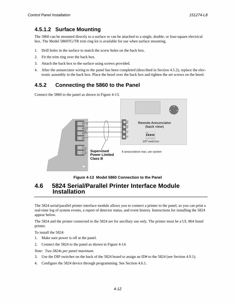
Control Panel Installation 151274-L8
4-12
4.5.1.2 Surface MountingThe 5860 can be mounted directly to a surface or can be attached to a single, double, or four-square electrical box. The Model 5860TG/TR trim ring kit is available for use when surface mounting.
1. Drill holes in the surface to match the screw holes on the back box.
2. Fit the trim ring over the back box.
3. Attach the back box to the surface using screws provided.
4. After the annunciator wiring to the panel has been completed (described in Section 4.5.2), replace the elec-tronic assembly in the back box. Place the bezel over the back box and tighten the set screws on the bezel.
4.5.2 Connecting the 5860 to the Panel
Connect the 5860 to the panel as shown in Figure 4-13.
Figure 4-13 Model 5860 Connection to the Panel
4.6 5824 Serial/Parallel Printer Interface Module Installation
The 5824 serial/parallel printer interface module allows you to connect a printer to the panel, so you can print a real-time log of system events, a report of detector status, and event history. Instructions for installing the 5824 appear below.
The 5824 and the printer connected to the 5824 are for ancillary use only. The printer must be a UL 864 listed printer.
To install the 5824:
1. Make sure power is off at the panel.
2. Connect the 5824 to the panel as shown in Figure 4-14.
Note: Two 5824s per panel maximum.
3. Use the DIP switches on the back of the 5824 board to assign an ID# to the 5824 (see Section 4.9.1).
4. Configure the 5824 device through programming. See Section 4.6.1.
SupervisedPower LimitedClass B
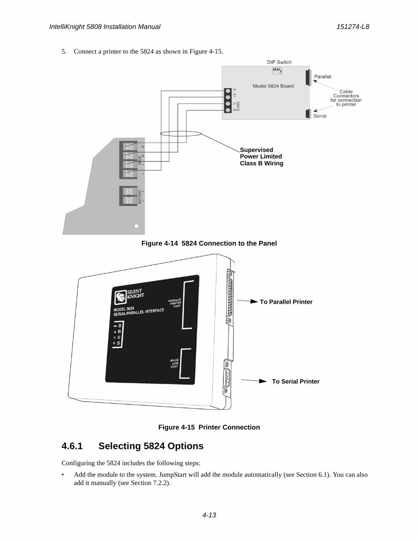
IntelliKnight 5808 Installation Manual 151274-L8
4-13
5. Connect a printer to the 5824 as shown in Figure 4-15.
Figure 4-14 5824 Connection to the Panel
Figure 4-15 Printer Connection
4.6.1 Selecting 5824 Options
Configuring the 5824 includes the following steps:
• Add the module to the system. JumpStart will add the module automatically (see Section 6.1). You can also add it manually (see Section 7.2.2).
SupervisedPower LimitedClass B Wiring
To Serial Printer
To Parallel Printer
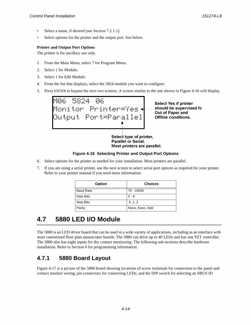
Control Panel Installation 151274-L8
4-14
• Select a name, if desired (see Section 7.2.1.1).
• Select options for the printer and the output port. See below.
Printer and Output Port OptionsThe printer is for ancillary use only.
1. From the Main Menu, select 7 for Program Menu.
2. Select 1 for Module.
3. Select 1 for Edit Module.
4. From the list that displays, select the 5824 module you want to configure.
5. Press ENTER to bypass the next two screens. A screen similar to the one shown in Figure 4-16 will display.
Figure 4-16 Selecting Printer and Output Port Options
6. Select options for the printer as needed for your installation. Most printers are parallel.
7. If you are using a serial printer, use the next screen to select serial port options as required for your printer. Refer to your printer manual if you need more information.
4.7 5880 LED I/O Module
The 5880 is an LED driver board that can be used in a wide variety of applications, including as an interface with most customized floor plan annunciator boards. The 5880 can drive up to 40 LEDs and has one PZT controller. The 5880 also has eight inputs for dry contact monitoring. The following sub-sections describe hardware installation. Refer to Section 6 for programming information.
4.7.1 5880 Board Layout
Figure 4-17 is a picture of the 5880 board showing locations of screw terminals for connection to the panel and contact monitor wiring; pin connectors for connecting LEDs; and the DIP switch for selecting an SBUS ID
Option Choices
Baud Rate: 75 - 19200
Data Bits: 5 - 8
Stop Bits: .5, 1, 2
Parity: None, Even, Odd
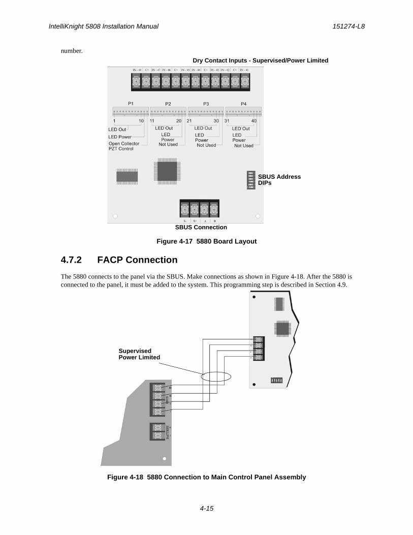
IntelliKnight 5808 Installation Manual 151274-L8
4-15
number.
Figure 4-17 5880 Board Layout
4.7.2 FACP Connection
The 5880 connects to the panel via the SBUS. Make connections as shown in Figure 4-18. After the 5880 is connected to the panel, it must be added to the system. This programming step is described in Section 4.9.
Figure 4-18 5880 Connection to Main Control Panel Assembly
SBUS Connection
Dry Contact Inputs - Supervised/Power Limited
SBUS AddressDIPs
SupervisedPower Limited
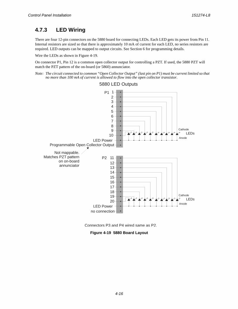
Control Panel Installation 151274-L8
4-16
4.7.3 LED Wiring
There are four 12-pin connectors on the 5880 board for connecting LEDs. Each LED gets its power from Pin 11. Internal resistors are sized so that there is approximately 10 mA of current for each LED, no series resistors are required. LED outputs can be mapped to output circuits. See Section 6 for programming details.
Wire the LEDs as shown in Figure 4-19.
On connector P1, Pin 12 is a common open collector output for controlling a PZT. If used, the 5880 PZT will match the PZT pattern of the on-board (or 5860) annunciator.
Note: The circuit connected to common “Open Collector Output” (last pin on P1) must be current limited so that no more than 100 mA of current is allowed to flow into the open collector transistor.
Figure 4-19 5880 Board Layout
11
20
1213141516171819
LED Powerno connection
Anode
Cathode
LEDs
P2
5880 LED Outputs
1
10
23456789
LED PowerProgrammable Open Collector Output
Not mappable.Matches PZT pattern
on on-board annunciator
Anode
Cathode
LEDs
P1
Connectors P3 and P4 wired same as P2.
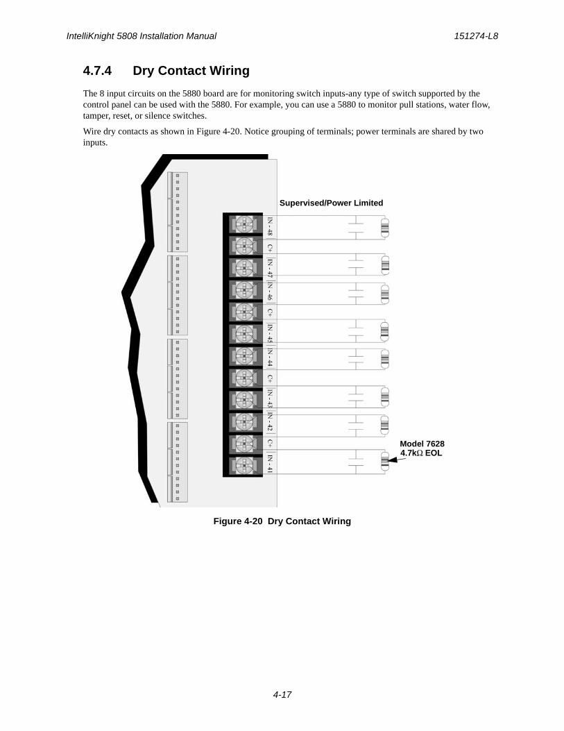
IntelliKnight 5808 Installation Manual 151274-L8
4-17
4.7.4 Dry Contact Wiring
The 8 input circuits on the 5880 board are for monitoring switch inputs-any type of switch supported by the control panel can be used with the 5880. For example, you can use a 5880 to monitor pull stations, water flow, tamper, reset, or silence switches.
Wire dry contacts as shown in Figure 4-20. Notice grouping of terminals; power terminals are shared by two inputs.
Figure 4-20 Dry Contact Wiring
Model 7628
Supervised/Power Limited
4.7kΩ EOL
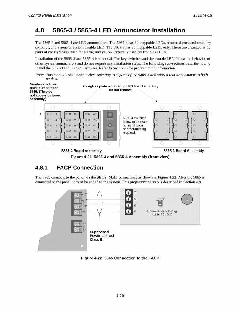
Control Panel Installation 151274-L8
4-18
4.8 5865-3 / 5865-4 LED Annunciator Installation
The 5865-3 and 5865-4 are LED annunciators. The 5865-4 has 30 mappable LEDs, remote silence and reset key switches, and a general system trouble LED. The 5865-3 has 30 mappable LEDs only. These are arranged as 15 pairs of red (typically used for alarm) and yellow (typically used for trouble) LEDs.
Installation of the 5865-3 and 5865-4 is identical. The key switches and the trouble LED follow the behavior of other system annunciators and do not require any installation steps. The following sub-sections describe how to install the 5865-3 and 5865-4 hardware. Refer to Section 6 for programming information.
Note: This manual uses “5865” when referring to aspects of the 5865-3 and 5865-4 that are common to both models.
Figure 4-21 5865-3 and 5865-4 Assembly (front view)
4.8.1 FACP Connection
The 5865 connects to the panel via the SBUS. Make connections as shown in Figure 4-22. After the 5865 is connected to the panel, it must be added to the system. This programming step is described in Section 4.9.
Figure 4-22 5865 Connection to the FACP
SILENCE
TROUBLE
RESET
5865-4 Board Assembly 5865-3 Board Assembly
Plexiglass plate mounted to LED board at factory.Do not remove.
5865-4 switchesfollow main FACP;no installationor programmingrequired.
Numbers indicatepoint numbers for5865. (They donot appear on boardassembly.)
1 2
9 10
11 12 21 22
19 20 29 30
3 4
5 6
7 8
13 14
15 16
17 18
23 24
25 26
27 28
SupervisedPower LimitedClass B
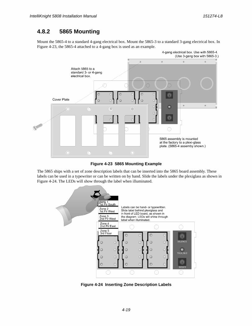
IntelliKnight 5808 Installation Manual 151274-L8
4-19
4.8.2 5865 Mounting
Mount the 5865-4 to a standard 4-gang electrical box. Mount the 5865-3 to a standard 3-gang electrical box. In Figure 4-23, the 5865-4 attached to a 4-gang box is used as an example.
Figure 4-23 5865 Mounting Example
The 5865 ships with a set of zone description labels that can be inserted into the 5865 board assembly. These labels can be used in a typewriter or can be written on by hand. Slide the labels under the plexiglass as shown in Figure 4-24. The LEDs will show through the label when illuminated.
Figure 4-24 Inserting Zone Description Labels
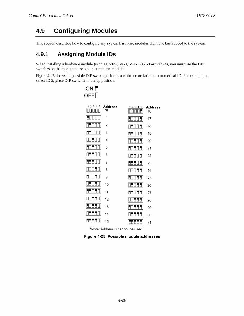
Control Panel Installation 151274-L8
4-20
4.9 Configuring Modules
This section describes how to configure any system hardware modules that have been added to the system.
4.9.1 Assigning Module IDs
When installing a hardware module (such as, 5824, 5860, 5496, 5865-3 or 5865-4), you must use the DIP switches on the module to assign an ID# to the module.
Figure 4-25 shows all possible DIP switch positions and their correlation to a numerical ID. For example, to select ID 2, place DIP switch 2 in the up position.
Figure 4-25 Possible module addresses
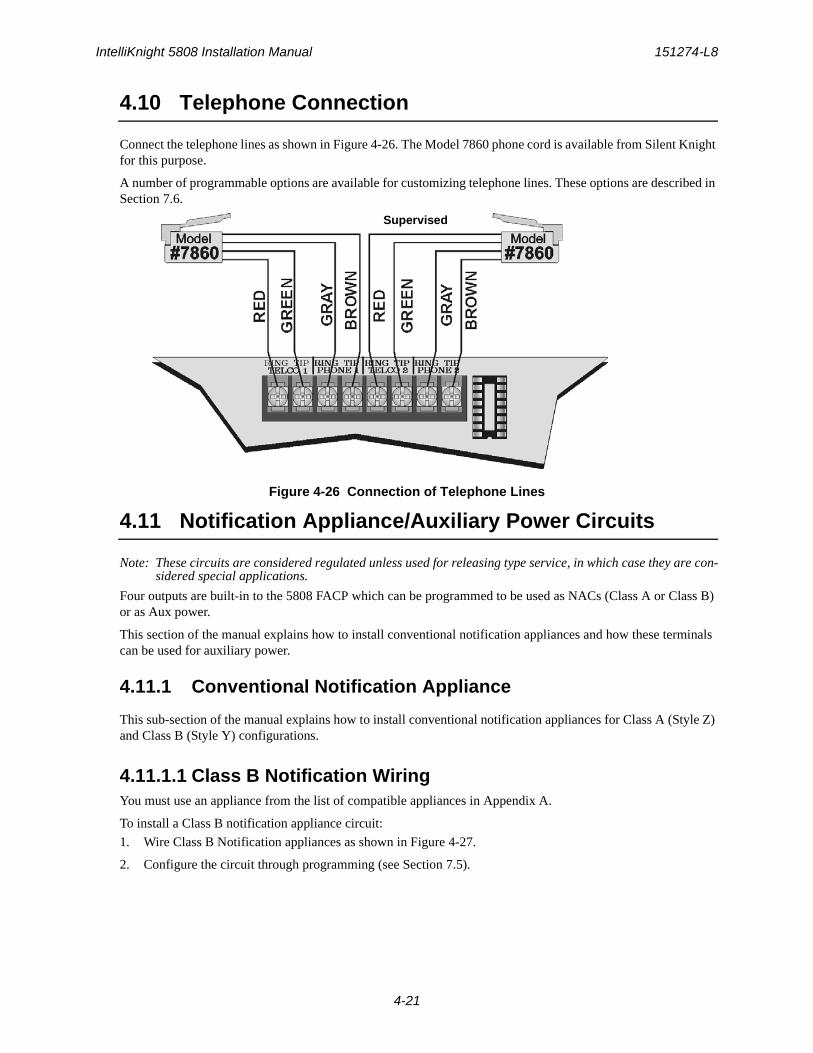
IntelliKnight 5808 Installation Manual 151274-L8
4-21
4.10 Telephone Connection
Connect the telephone lines as shown in Figure 4-26. The Model 7860 phone cord is available from Silent Knight for this purpose.
A number of programmable options are available for customizing telephone lines. These options are described in Section 7.6.
Figure 4-26 Connection of Telephone Lines
4.11 Notification Appliance/Auxiliary Power Circuits
Note: These circuits are considered regulated unless used for releasing type service, in which case they are con-sidered special applications.
Four outputs are built-in to the 5808 FACP which can be programmed to be used as NACs (Class A or Class B) or as Aux power.
This section of the manual explains how to install conventional notification appliances and how these terminals can be used for auxiliary power.
4.11.1 Conventional Notification Appliance
This sub-section of the manual explains how to install conventional notification appliances for Class A (Style Z) and Class B (Style Y) configurations.
4.11.1.1 Class B Notification WiringYou must use an appliance from the list of compatible appliances in Appendix A.
To install a Class B notification appliance circuit:
1. Wire Class B Notification appliances as shown in Figure 4-27.
2. Configure the circuit through programming (see Section 7.5).
Supervised
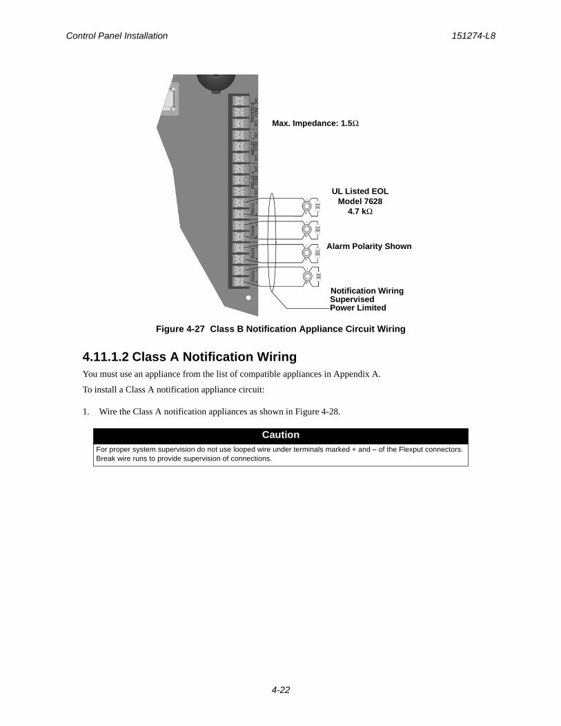
Control Panel Installation 151274-L8
4-22
Figure 4-27 Class B Notification Appliance Circuit Wiring
4.11.1.2 Class A Notification WiringYou must use an appliance from the list of compatible appliances in Appendix A.
To install a Class A notification appliance circuit:
1. Wire the Class A notification appliances as shown in Figure 4-28.
CautionFor proper system supervision do not use looped wire under terminals marked + and – of the Flexput connectors. Break wire runs to provide supervision of connections.
Alarm Polarity Shown
UL Listed EOLModel 7628
4.7 kΩ
SupervisedPower Limited
Notification Wiring
Max. Impedance: 1.5Ω
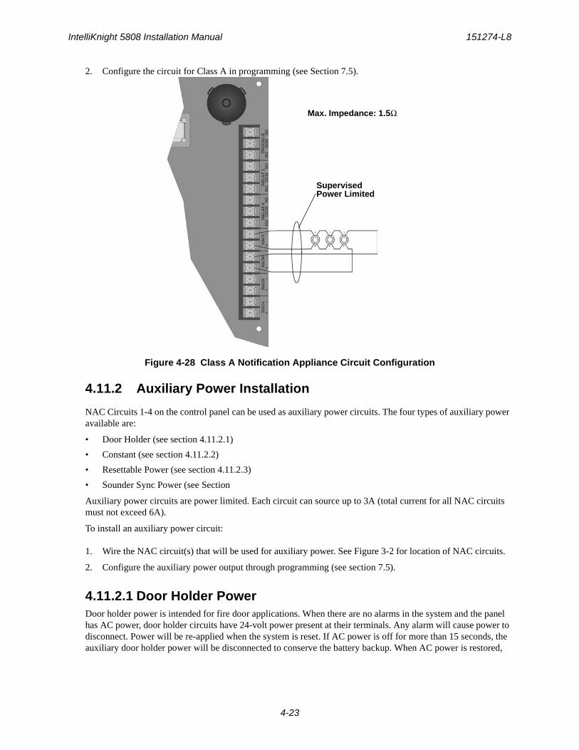
IntelliKnight 5808 Installation Manual 151274-L8
4-23
2. Configure the circuit for Class A in programming (see Section 7.5).
Figure 4-28 Class A Notification Appliance Circuit Configuration
4.11.2 Auxiliary Power Installation
NAC Circuits 1-4 on the control panel can be used as auxiliary power circuits. The four types of auxiliary power available are:
• Door Holder (see section 4.11.2.1)
• Constant (see section 4.11.2.2)
• Resettable Power (see section 4.11.2.3)
• Sounder Sync Power (see Section
Auxiliary power circuits are power limited. Each circuit can source up to 3A (total current for all NAC circuits must not exceed 6A).
To install an auxiliary power circuit:
1. Wire the NAC circuit(s) that will be used for auxiliary power. See Figure 3-2 for location of NAC circuits.
2. Configure the auxiliary power output through programming (see section 7.5).
4.11.2.1 Door Holder PowerDoor holder power is intended for fire door applications. When there are no alarms in the system and the panel has AC power, door holder circuits have 24-volt power present at their terminals. Any alarm will cause power to disconnect. Power will be re-applied when the system is reset. If AC power is off for more than 15 seconds, the auxiliary door holder power will be disconnected to conserve the battery backup. When AC power is restored,
SupervisedPower Limited
Max. Impedance: 1.5Ω
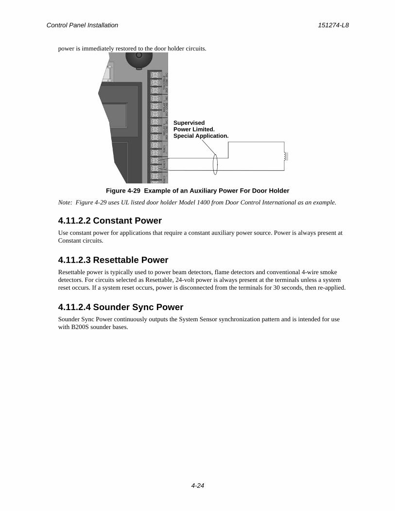
Control Panel Installation 151274-L8
4-24
power is immediately restored to the door holder circuits.
Figure 4-29 Example of an Auxiliary Power For Door Holder
Note: Figure 4-29 uses UL listed door holder Model 1400 from Door Control International as an example.
4.11.2.2 Constant PowerUse constant power for applications that require a constant auxiliary power source. Power is always present at Constant circuits.
4.11.2.3 Resettable PowerResettable power is typically used to power beam detectors, flame detectors and conventional 4-wire smoke detectors. For circuits selected as Resettable, 24-volt power is always present at the terminals unless a system reset occurs. If a system reset occurs, power is disconnected from the terminals for 30 seconds, then re-applied.
4.11.2.4 Sounder Sync PowerSounder Sync Power continuously outputs the System Sensor synchronization pattern and is intended for use with B200S sounder bases.
SupervisedPower Limited.Special Application.
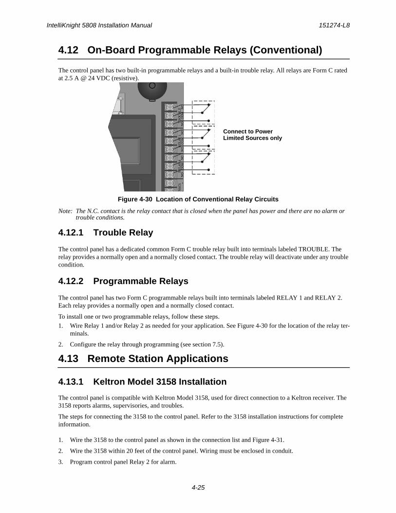
IntelliKnight 5808 Installation Manual 151274-L8
4-25
4.12 On-Board Programmable Relays (Conventional)
The control panel has two built-in programmable relays and a built-in trouble relay. All relays are Form C rated at 2.5 A @ 24 VDC (resistive).
Figure 4-30 Location of Conventional Relay Circuits
Note: The N.C. contact is the relay contact that is closed when the panel has power and there are no alarm or trouble conditions.
4.12.1 Trouble Relay
The control panel has a dedicated common Form C trouble relay built into terminals labeled TROUBLE. The relay provides a normally open and a normally closed contact. The trouble relay will deactivate under any trouble condition.
4.12.2 Programmable Relays
The control panel has two Form C programmable relays built into terminals labeled RELAY 1 and RELAY 2. Each relay provides a normally open and a normally closed contact.
To install one or two programmable relays, follow these steps.
1. Wire Relay 1 and/or Relay 2 as needed for your application. See Figure 4-30 for the location of the relay ter-minals.
2. Configure the relay through programming (see section 7.5).
4.13 Remote Station Applications
4.13.1 Keltron Model 3158 Installation
The control panel is compatible with Keltron Model 3158, used for direct connection to a Keltron receiver. The 3158 reports alarms, supervisories, and troubles.
The steps for connecting the 3158 to the control panel. Refer to the 3158 installation instructions for complete information.
1. Wire the 3158 to the control panel as shown in the connection list and Figure 4-31.
2. Wire the 3158 within 20 feet of the control panel. Wiring must be enclosed in conduit.
3. Program control panel Relay 2 for alarm.
Connect to PowerLimited Sources only
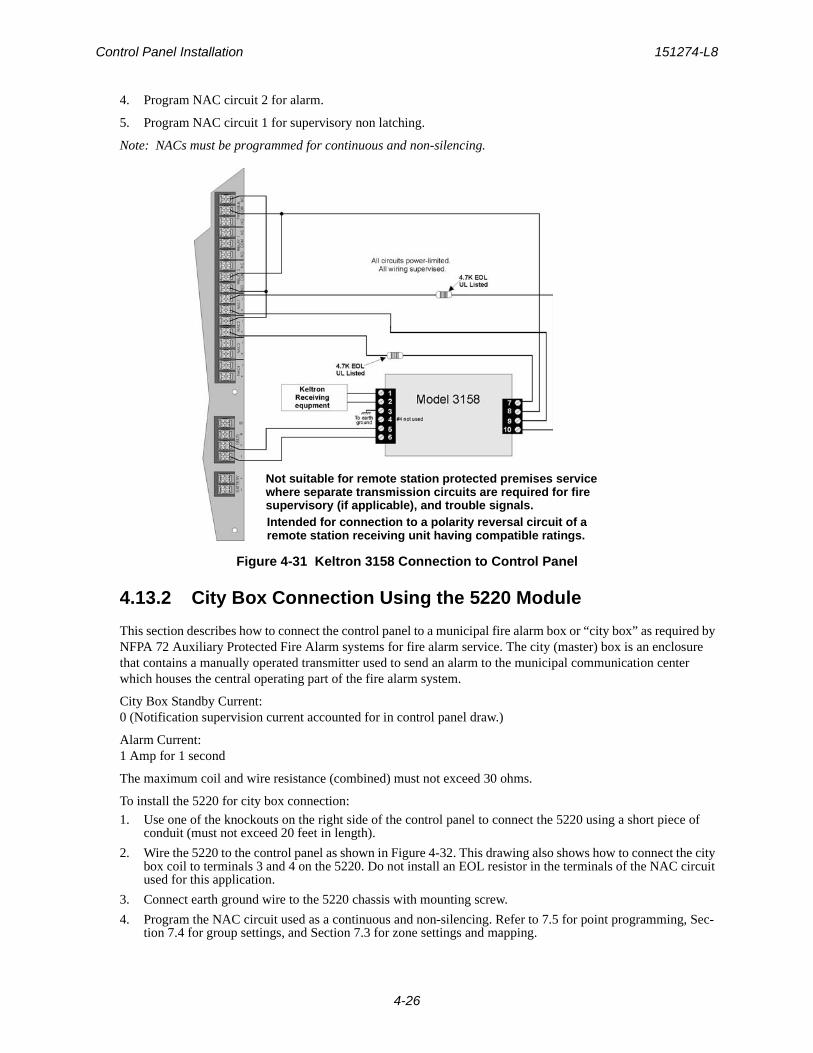
Control Panel Installation 151274-L8
4-26
4. Program NAC circuit 2 for alarm.
5. Program NAC circuit 1 for supervisory non latching.
Note: NACs must be programmed for continuous and non-silencing.
Figure 4-31 Keltron 3158 Connection to Control Panel
4.13.2 City Box Connection Using the 5220 Module
This section describes how to connect the control panel to a municipal fire alarm box or “city box” as required by NFPA 72 Auxiliary Protected Fire Alarm systems for fire alarm service. The city (master) box is an enclosure that contains a manually operated transmitter used to send an alarm to the municipal communication center which houses the central operating part of the fire alarm system.
City Box Standby Current: 0 (Notification supervision current accounted for in control panel draw.)
Alarm Current: 1 Amp for 1 second
The maximum coil and wire resistance (combined) must not exceed 30 ohms.
To install the 5220 for city box connection:
1. Use one of the knockouts on the right side of the control panel to connect the 5220 using a short piece of conduit (must not exceed 20 feet in length).
2. Wire the 5220 to the control panel as shown in Figure 4-32. This drawing also shows how to connect the city box coil to terminals 3 and 4 on the 5220. Do not install an EOL resistor in the terminals of the NAC circuit used for this application.
3. Connect earth ground wire to the 5220 chassis with mounting screw.
4. Program the NAC circuit used as a continuous and non-silencing. Refer to 7.5 for point programming, Sec-tion 7.4 for group settings, and Section 7.3 for zone settings and mapping.
Not suitable for remote station protected premises servicewhere separate transmission circuits are required for fire supervisory (if applicable), and trouble signals.Intended for connection to a polarity reversal circuit of aremote station receiving unit having compatible ratings.
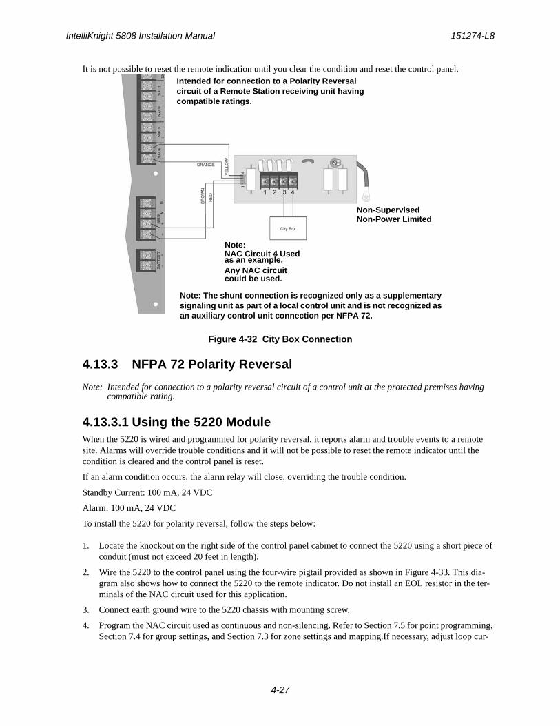
IntelliKnight 5808 Installation Manual 151274-L8
4-27
It is not possible to reset the remote indication until you clear the condition and reset the control panel.
Figure 4-32 City Box Connection
4.13.3 NFPA 72 Polarity Reversal
Note: Intended for connection to a polarity reversal circuit of a control unit at the protected premises having compatible rating.
4.13.3.1 Using the 5220 ModuleWhen the 5220 is wired and programmed for polarity reversal, it reports alarm and trouble events to a remote site. Alarms will override trouble conditions and it will not be possible to reset the remote indicator until the condition is cleared and the control panel is reset.
If an alarm condition occurs, the alarm relay will close, overriding the trouble condition.
Standby Current: 100 mA, 24 VDC
Alarm: 100 mA, 24 VDC
To install the 5220 for polarity reversal, follow the steps below:
1. Locate the knockout on the right side of the control panel cabinet to connect the 5220 using a short piece of conduit (must not exceed 20 feet in length).
2. Wire the 5220 to the control panel using the four-wire pigtail provided as shown in Figure 4-33. This dia-gram also shows how to connect the 5220 to the remote indicator. Do not install an EOL resistor in the ter-minals of the NAC circuit used for this application.
3. Connect earth ground wire to the 5220 chassis with mounting screw.
4. Program the NAC circuit used as continuous and non-silencing. Refer to Section 7.5 for point programming, Section 7.4 for group settings, and Section 7.3 for zone settings and mapping.If necessary, adjust loop cur-
Note:NAC Circuit 4 Used
Any NAC circuit could be used.
Non-SupervisedNon-Power Limited
Intended for connection to a Polarity Reversal circuit of a Remote Station receiving unit having compatible ratings.
Note: The shunt connection is recognized only as a supplementary signaling unit as part of a local control unit and is not recognized as an auxiliary control unit connection per NFPA 72.
as an example.
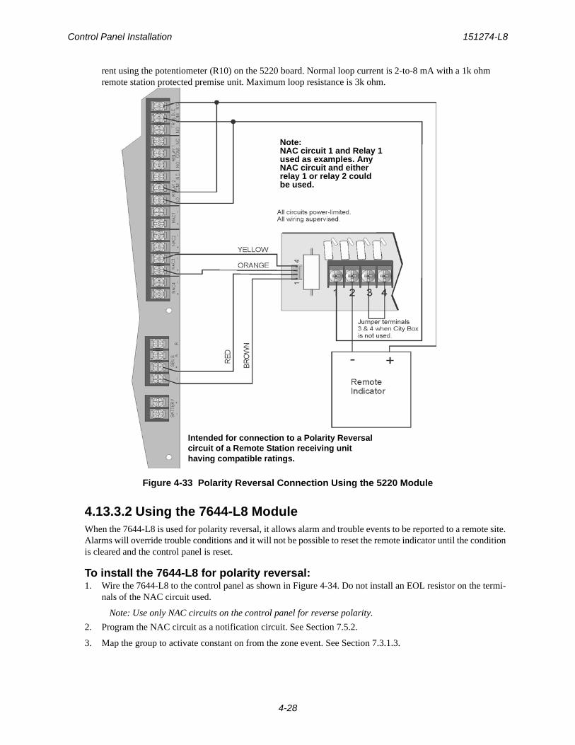
Control Panel Installation 151274-L8
4-28
rent using the potentiometer (R10) on the 5220 board. Normal loop current is 2-to-8 mA with a 1k ohm remote station protected premise unit. Maximum loop resistance is 3k ohm.
Figure 4-33 Polarity Reversal Connection Using the 5220 Module
4.13.3.2 Using the 7644-L8 ModuleWhen the 7644-L8 is used for polarity reversal, it allows alarm and trouble events to be reported to a remote site. Alarms will override trouble conditions and it will not be possible to reset the remote indicator until the condition is cleared and the control panel is reset.
To install the 7644-L8 for polarity reversal:1. Wire the 7644-L8 to the control panel as shown in Figure 4-34. Do not install an EOL resistor on the termi-
nals of the NAC circuit used.
Note: Use only NAC circuits on the control panel for reverse polarity.
2. Program the NAC circuit as a notification circuit. See Section 7.5.2.
3. Map the group to activate constant on from the zone event. See Section 7.3.1.3.
Note:NAC circuit 1 and Relay 1used as examples. AnyNAC circuit and eitherrelay 1 or relay 2 couldbe used.
Intended for connection to a Polarity Reversal circuit of a Remote Station receiving unit having compatible ratings.
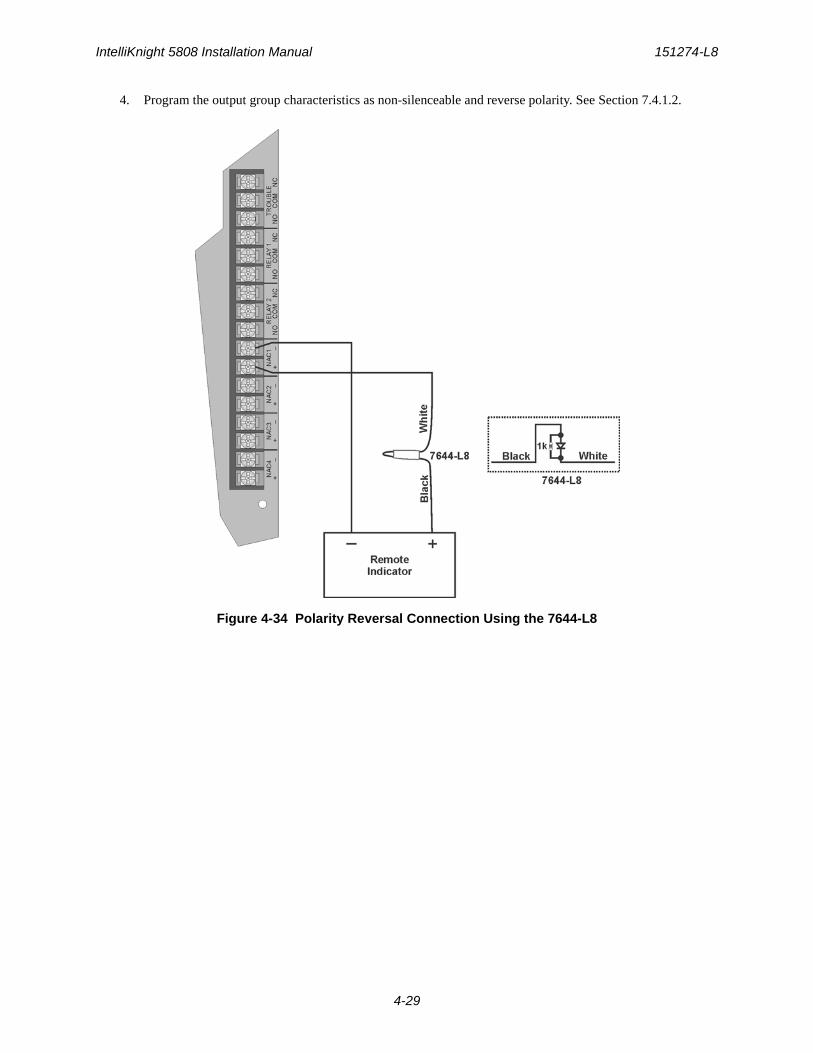
IntelliKnight 5808 Installation Manual 151274-L8
4-29
4. Program the output group characteristics as non-silenceable and reverse polarity. See Section 7.4.1.2.
Figure 4-34 Polarity Reversal Connection Using the 7644-L8
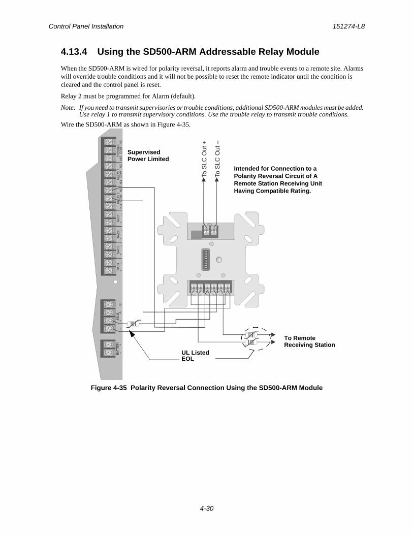
Control Panel Installation 151274-L8
4-30
4.13.4 Using the SD500-ARM Addressable Relay Module
When the SD500-ARM is wired for polarity reversal, it reports alarm and trouble events to a remote site. Alarms will override trouble conditions and it will not be possible to reset the remote indicator until the condition is cleared and the control panel is reset.
Relay 2 must be programmed for Alarm (default).
Note: If you need to transmit supervisories or trouble conditions, additional SD500-ARM modules must be added. Use relay 1 to transmit supervisory conditions. Use the trouble relay to transmit trouble conditions.
Wire the SD500-ARM as shown in Figure 4-35.
Figure 4-35 Polarity Reversal Connection Using the SD500-ARM Module
UL ListedEOL
To Remote
Intended for Connection to a Polarity Reversal Circuit of A Remote Station Receiving Unit Having Compatible Rating.
SupervisedPower Limited
Receiving Station
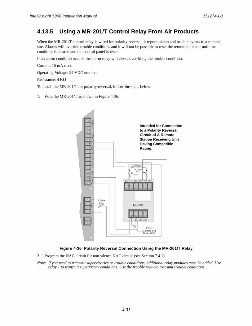
IntelliKnight 5808 Installation Manual 151274-L8
4-31
4.13.5 Using a MR-201/T Control Relay From Air Products
When the MR-201/T control relay is wired for polarity reversal, it reports alarm and trouble events to a remote site. Alarms will override trouble conditions and it will not be possible to reset the remote indicator until the condition is cleared and the control panel is reset.
If an alarm condition occurs, the alarm relay will close, overriding the trouble condition.
Current: 15 mA max.
Operating Voltage: 24 VDC nominal
Resistance: 4 KΩ
To install the MR-201/T for polarity reversal, follow the steps below:
1. Wire the MR-201/T as shown in Figure 4-36.
Figure 4-36 Polarity Reversal Connection Using the MR-201/T Relay
2. Program the NAC circuit for non silence NAC circuit (see Section 7.4.1).
Note: If you need to transmit supervisories or trouble conditions, additional relay modules must be added. Use relay 1 to transmit supervisory conditions. Use the trouble relay to transmit trouble conditions.
Intended for Connection to a Polarity Reversal Circuit of A Remote Station Receiving Unit Having Compatible Rating.
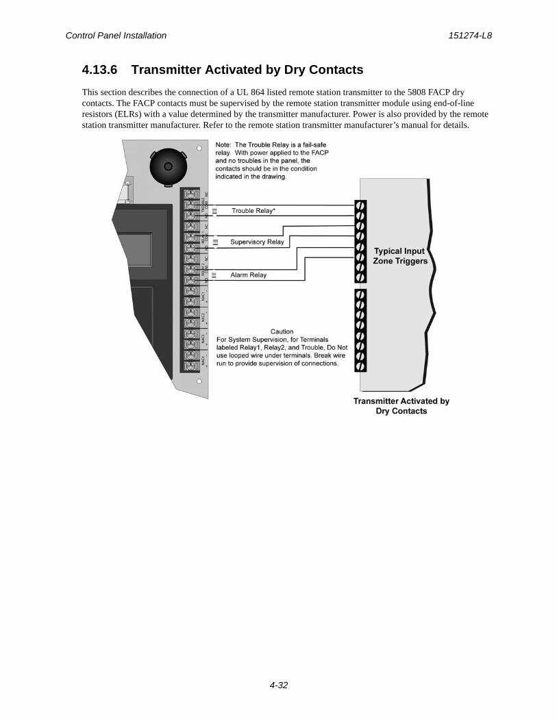
Control Panel Installation 151274-L8
4-32
4.13.6 Transmitter Activated by Dry Contacts
This section describes the connection of a UL 864 listed remote station transmitter to the 5808 FACP dry contacts. The FACP contacts must be supervised by the remote station transmitter module using end-of-line resistors (ELRs) with a value determined by the transmitter manufacturer. Power is also provided by the remote station transmitter manufacturer. Refer to the remote station transmitter manufacturer’s manual for details.
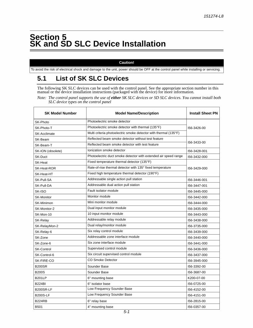
151274-L8
5-1
Section 5SK and SD SLC Device Installation
5.1 List of SK SLC DevicesThe following SK SLC devices can be used with the control panel. See the appropriate section number in this manual or the device installation instructions (packaged with the device) for more information.
Note: The control panel supports the use of either SK SLC devices or SD SLC devices. You cannot install both SLC device types on the control panel
Caution!
To avoid the risk of electrical shock and damage to the unit, power should be OFF at the control panel while installing or servicing.
SK Model Number Model Name/Description Install Sheet PN
SK-Photo Photoelectric smoke detector
I56-3426-00SK-Photo-T Photoelectric smoke detector with thermal (135°F)
SK-Acclimate Multi criteria photoelectric smoke detector with thermal (135°F)
SK-Beam Reflected beam smoke detector without test featureI56-3433-00
SK-Beam-T Reflected beam smoke detector with test feature
SK-ION (obsolete) Ionization smoke detector I56-3428-001
SK-Duct Photoelectric duct smoke detector with extended air speed range I56-3432-000
SK-Heat Fixed temperature thermal detector (135°F)
I56-3429-000SK-Heat-ROR Rate-of-rise thermal detector with 135° fixed temperature
SK-Heat-HT Fixed high temperature thermal detector (190°F)
SK-Pull-SA Addressable single action pull station I56-3446-001
SK-Pull-DA Addressable dual action pull station I56-3447-001
SK-ISO Fault isolator module I56-3445-000
SK-Monitor Monitor module I56-3442-000
SK-Minimon Mini monitor module I56-3444-000
SK-Monitor-2 Dual input monitor module I56-3435-000
SK-Mon-10 10 input monitor module I56-3443-000
SK-Relay Addressable relay module I56-3438-000
SK-RelayMon-2 Dual relay/monitor module I56-3735-000
SK-Relay-6 Six relay control module I56-3439-000
SK-Zone Addressable zone interface module I56-3440-000
SK-Zone-6 Six zone interface module I56-3441-000
SK-Control Supervised control module I56-3436-000
SK-Control-6 Six circuit supervised control module I56-3437-000
SK-FIRE-CO CO Smoke Detector I56-3945-000
B200SR Sounder Base I56-3392-00
B200S Sounder Base I56-3687-00
B201LP 6" mounting base K200-07-00
B224BI 6" isolator base I56-0725-00
B200SR-LF Low Frequency Sounder Base I56-4152-00
B200S-LF Low Frequency Sounder Base I56-4151-00
B224RB 6" relay base I56-2815-00
B501 4" mounting base I56-0357-00
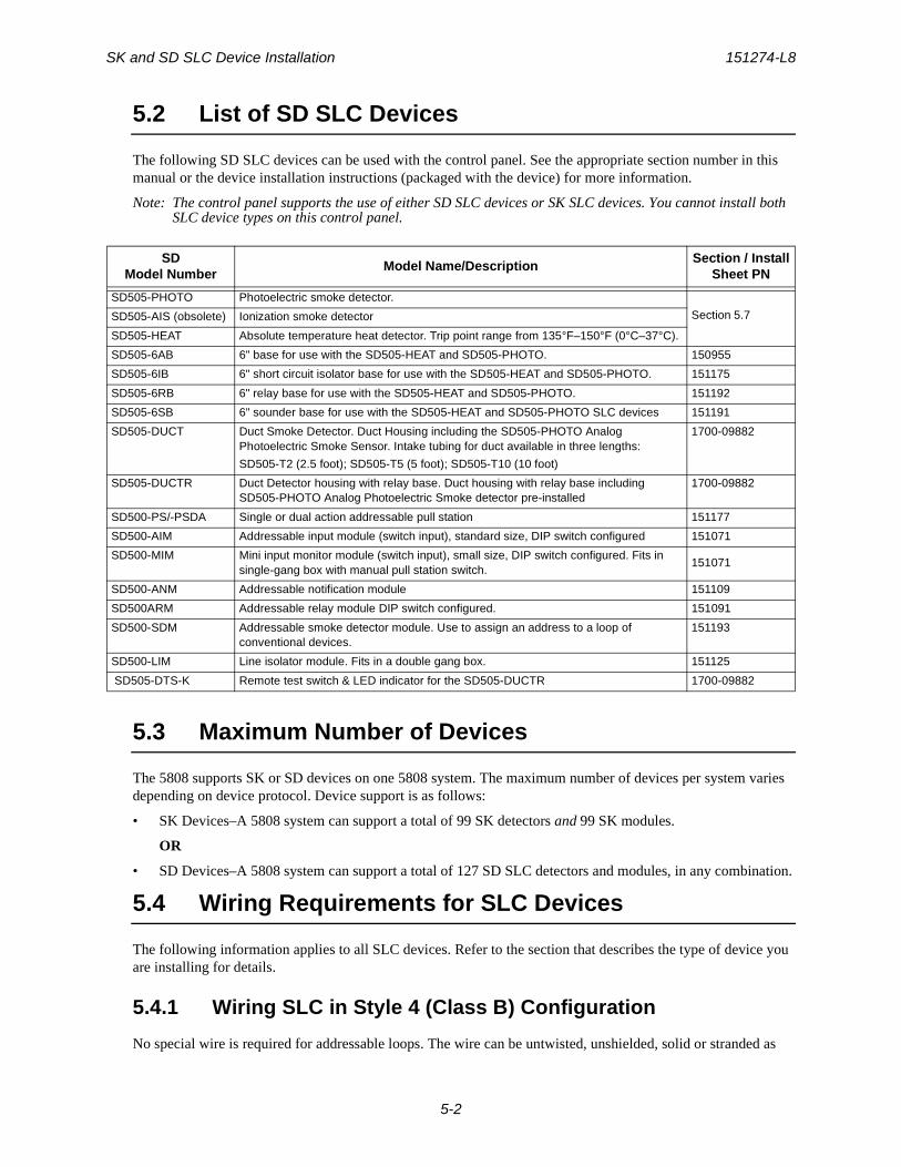
SK and SD SLC Device Installation 151274-L8
5-2
5.2 List of SD SLC Devices
The following SD SLC devices can be used with the control panel. See the appropriate section number in this manual or the device installation instructions (packaged with the device) for more information.
Note: The control panel supports the use of either SD SLC devices or SK SLC devices. You cannot install both SLC device types on this control panel.
5.3 Maximum Number of Devices
The 5808 supports SK or SD devices on one 5808 system. The maximum number of devices per system varies depending on device protocol. Device support is as follows:
• SK Devices–A 5808 system can support a total of 99 SK detectors and 99 SK modules.
OR
• SD Devices–A 5808 system can support a total of 127 SD SLC detectors and modules, in any combination.
5.4 Wiring Requirements for SLC Devices
The following information applies to all SLC devices. Refer to the section that describes the type of device you are installing for details.
5.4.1 Wiring SLC in Style 4 (Class B) Configuration
No special wire is required for addressable loops. The wire can be untwisted, unshielded, solid or stranded as
SDModel Number
Model Name/DescriptionSection / Install
Sheet PN
SD505-PHOTO Photoelectric smoke detector.
Section 5.7SD505-AIS (obsolete) Ionization smoke detector
SD505-HEAT Absolute temperature heat detector. Trip point range from 135°F–150°F (0°C–37°C).
SD505-6AB 6" base for use with the SD505-HEAT and SD505-PHOTO. 150955
SD505-6IB 6" short circuit isolator base for use with the SD505-HEAT and SD505-PHOTO. 151175
SD505-6RB 6" relay base for use with the SD505-HEAT and SD505-PHOTO. 151192
SD505-6SB 6" sounder base for use with the SD505-HEAT and SD505-PHOTO SLC devices 151191
SD505-DUCT Duct Smoke Detector. Duct Housing including the SD505-PHOTO Analog Photoelectric Smoke Sensor. Intake tubing for duct available in three lengths:
SD505-T2 (2.5 foot); SD505-T5 (5 foot); SD505-T10 (10 foot)
1700-09882
SD505-DUCTR Duct Detector housing with relay base. Duct housing with relay base including SD505-PHOTO Analog Photoelectric Smoke detector pre-installed
1700-09882
SD500-PS/-PSDA Single or dual action addressable pull station 151177
SD500-AIM Addressable input module (switch input), standard size, DIP switch configured 151071
SD500-MIM Mini input monitor module (switch input), small size, DIP switch configured. Fits in single-gang box with manual pull station switch.
151071
SD500-ANM Addressable notification module 151109
SD500ARM Addressable relay module DIP switch configured. 151091
SD500-SDM Addressable smoke detector module. Use to assign an address to a loop of conventional devices.
151193
SD500-LIM Line isolator module. Fits in a double gang box. 151125
SD505-DTS-K Remote test switch & LED indicator for the SD505-DUCTR 1700-09882
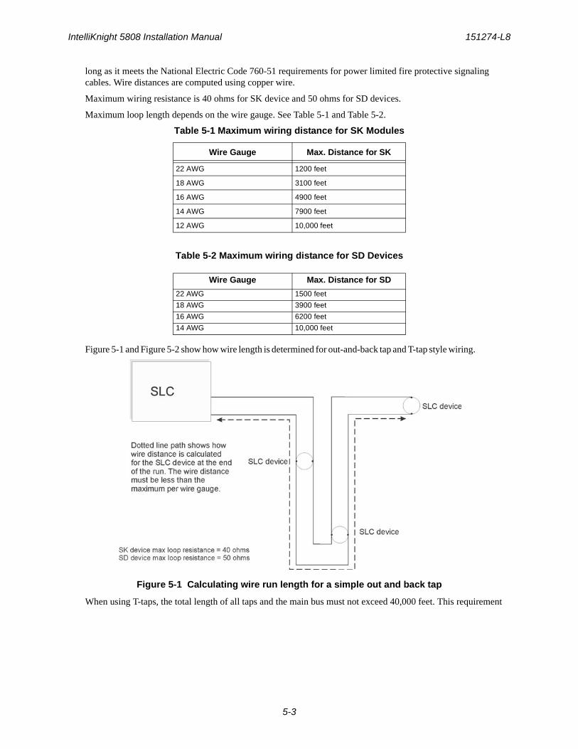
IntelliKnight 5808 Installation Manual 151274-L8
5-3
long as it meets the National Electric Code 760-51 requirements for power limited fire protective signaling cables. Wire distances are computed using copper wire.
Maximum wiring resistance is 40 ohms for SK device and 50 ohms for SD devices.
Maximum loop length depends on the wire gauge. See Table 5-1 and Table 5-2.
Table 5-1 Maximum wiring distance for SK Modules
Table 5-2 Maximum wiring distance for SD Devices
Figure 5-1 and Figure 5-2 show how wire length is determined for out-and-back tap and T-tap style wiring.
Figure 5-1 Calculating wire run length for a simple out and back tap
When using T-taps, the total length of all taps and the main bus must not exceed 40,000 feet. This requirement
Wire Gauge Max. Distance for SK
22 AWG 1200 feet
18 AWG 3100 feet
16 AWG 4900 feet
14 AWG 7900 feet
12 AWG 10,000 feet
Wire Gauge Max. Distance for SD
22 AWG 1500 feet
18 AWG 3900 feet
16 AWG 6200 feet
14 AWG 10,000 feet
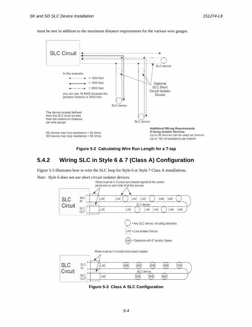
SK and SD SLC Device Installation 151274-L8
5-4
must be met in addition to the maximum distance requirements for the various wire gauges.
Figure 5-2 Calculating Wire Run Length for a T-tap
5.4.2 Wiring SLC in Style 6 & 7 (Class A) Configuration
Figure 5-3 illustrates how to wire the SLC loop for Style 6 or Style 7 Class A installations.
Note: Style 6 does not use short circuit isolator devices.
Figure 5-3 Class A SLC Configuration
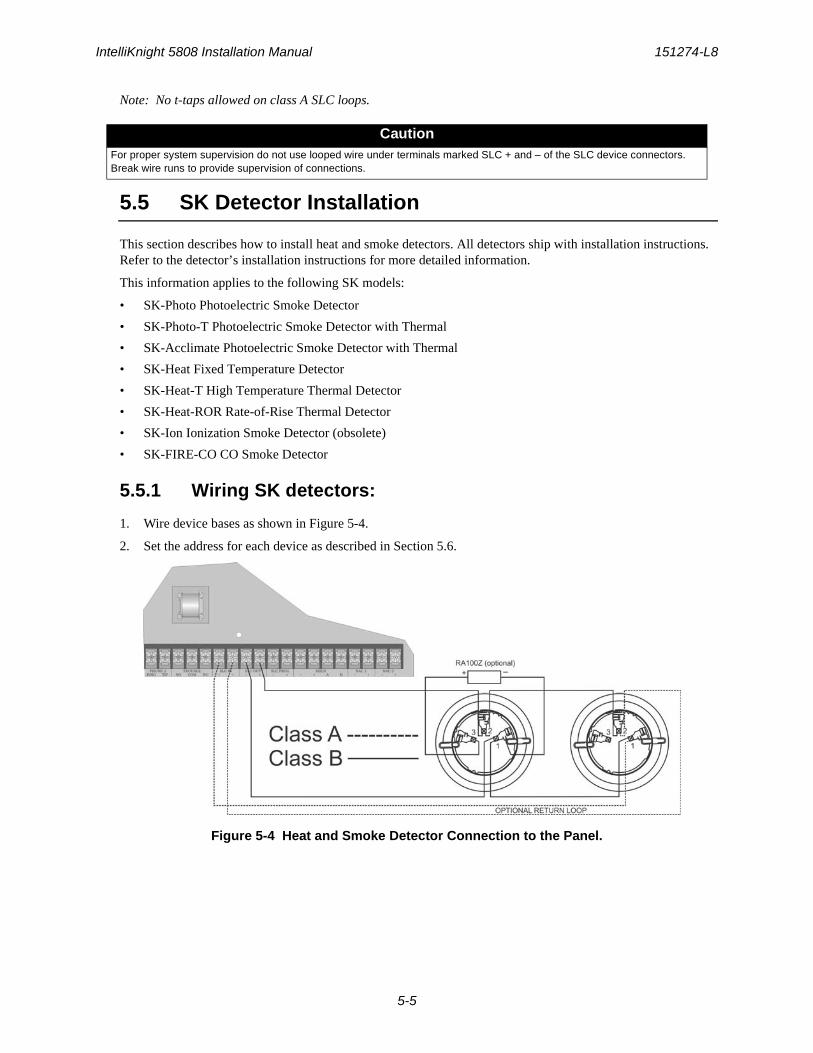
IntelliKnight 5808 Installation Manual 151274-L8
5-5
Note: No t-taps allowed on class A SLC loops.
5.5 SK Detector Installation
This section describes how to install heat and smoke detectors. All detectors ship with installation instructions. Refer to the detector’s installation instructions for more detailed information.
This information applies to the following SK models:
• SK-Photo Photoelectric Smoke Detector
• SK-Photo-T Photoelectric Smoke Detector with Thermal
• SK-Acclimate Photoelectric Smoke Detector with Thermal
• SK-Heat Fixed Temperature Detector
• SK-Heat-T High Temperature Thermal Detector
• SK-Heat-ROR Rate-of-Rise Thermal Detector
• SK-Ion Ionization Smoke Detector (obsolete)
• SK-FIRE-CO CO Smoke Detector
5.5.1 Wiring SK detectors:
1. Wire device bases as shown in Figure 5-4.
2. Set the address for each device as described in Section 5.6.
Figure 5-4 Heat and Smoke Detector Connection to the Panel.
CautionFor proper system supervision do not use looped wire under terminals marked SLC + and – of the SLC device connectors. Break wire runs to provide supervision of connections.
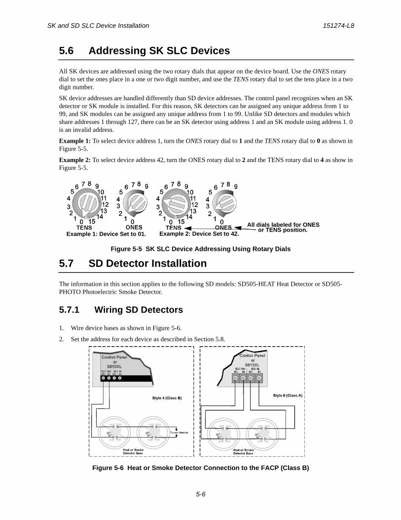
SK and SD SLC Device Installation 151274-L8
5-6
5.6 Addressing SK SLC Devices
All SK devices are addressed using the two rotary dials that appear on the device board. Use the ONES rotary dial to set the ones place in a one or two digit number, and use the TENS rotary dial to set the tens place in a two digit number.
SK device addresses are handled differently than SD device addresses. The control panel recognizes when an SK detector or SK module is installed. For this reason, SK detectors can be assigned any unique address from 1 to 99, and SK modules can be assigned any unique address from 1 to 99. Unlike SD detectors and modules which share addresses 1 through 127, there can be an SK detector using address 1 and an SK module using address 1. 0 is an invalid address.
Example 1: To select device address 1, turn the ONES rotary dial to 1 and the TENS rotary dial to 0 as shown in Figure 5-5.
Example 2: To select device address 42, turn the ONES rotary dial to 2 and the TENS rotary dial to 4 as show in Figure 5-5.
Figure 5-5 SK SLC Device Addressing Using Rotary Dials
5.7 SD Detector Installation
The information in this section applies to the following SD models: SD505-HEAT Heat Detector or SD505-PHOTO Photoelectric Smoke Detector.
5.7.1 Wiring SD Detectors
1. Wire device bases as shown in Figure 5-6.
2. Set the address for each device as described in Section 5.8.
Figure 5-6 Heat or Smoke Detector Connection to the FACP (Class B)
Example 1: Device Set to 01. Example 2: Device Set to 42.
All dials labeled for ONESor TENS position.
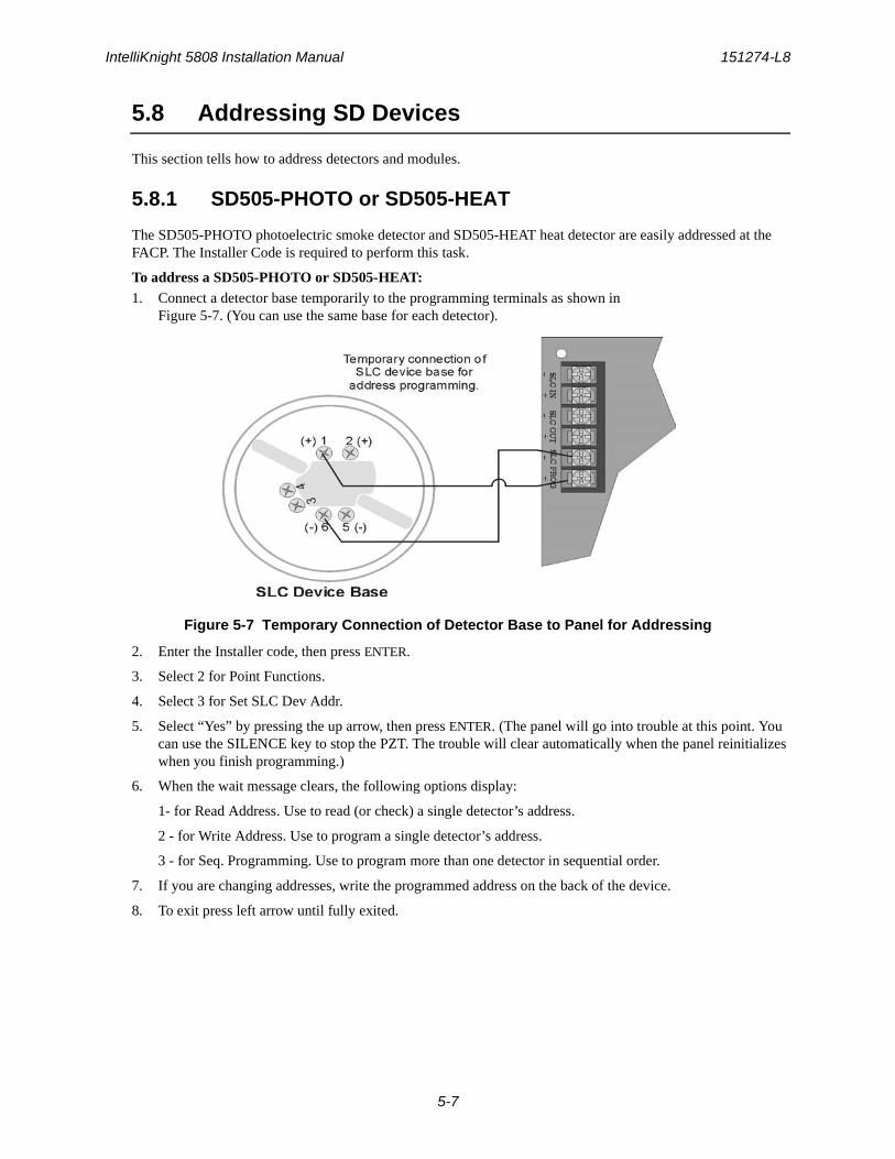
IntelliKnight 5808 Installation Manual 151274-L8
5-7
5.8 Addressing SD Devices
This section tells how to address detectors and modules.
5.8.1 SD505-PHOTO or SD505-HEAT
The SD505-PHOTO photoelectric smoke detector and SD505-HEAT heat detector are easily addressed at the FACP. The Installer Code is required to perform this task.
To address a SD505-PHOTO or SD505-HEAT:1. Connect a detector base temporarily to the programming terminals as shown in
Figure 5-7. (You can use the same base for each detector).
Figure 5-7 Temporary Connection of Detector Base to Panel for Addressing
2. Enter the Installer code, then press ENTER.
3. Select 2 for Point Functions.
4. Select 3 for Set SLC Dev Addr.
5. Select “Yes” by pressing the up arrow, then press ENTER. (The panel will go into trouble at this point. You can use the SILENCE key to stop the PZT. The trouble will clear automatically when the panel reinitializes when you finish programming.)
6. When the wait message clears, the following options display:
1- for Read Address. Use to read (or check) a single detector’s address.
2 - for Write Address. Use to program a single detector’s address.
3 - for Seq. Programming. Use to program more than one detector in sequential order.
7. If you are changing addresses, write the programmed address on the back of the device.
8. To exit press left arrow until fully exited.
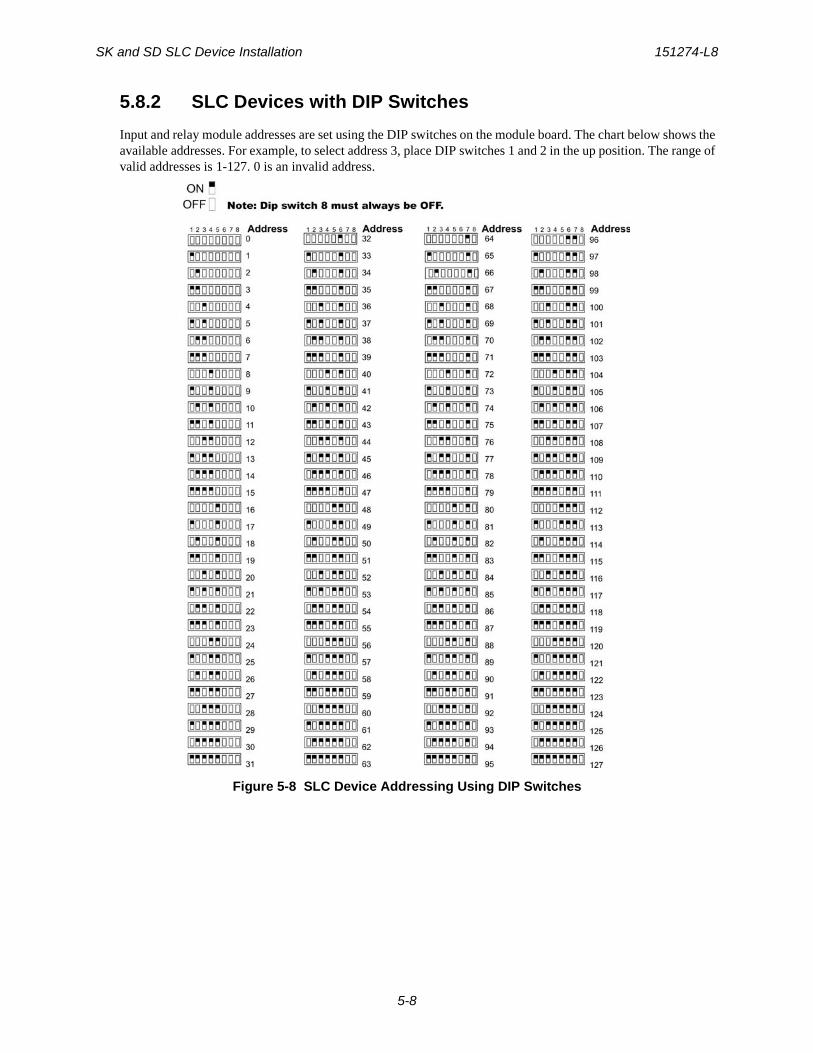
SK and SD SLC Device Installation 151274-L8
5-8
5.8.2 SLC Devices with DIP Switches
Input and relay module addresses are set using the DIP switches on the module board. The chart below shows the available addresses. For example, to select address 3, place DIP switches 1 and 2 in the up position. The range of valid addresses is 1-127. 0 is an invalid address.
Figure 5-8 SLC Device Addressing Using DIP Switches
151274-L8
6-1
Section 6Programming Overview
This section of the manual is intended to give you an overview of the programming process. Please read this section of the manual carefully, especially if you are programming the control panel for the first time.
The JumpStart feature automates many programming tasks and selects default options for the system. You will run JumpStart at least once when you are installing the system. See Section 6.1 for details. After you run JumpStart, you may need to do some additional programming depending on your installation. Section 7 of this manual covers manual programmable options in detail.
Programming the panel can be thought of as a three part process. You must program:
• System options. These are options that affect general operation of the panel (see Section 7.6 for details).
• Options for input points and zones. These are primarily options that control detection behavior of devices (see Section 7.5 for details).
• Options for output points and groups. This includes selecting characteristics for output groups and mapping output circuits to output groups (see Section 7.5 for details).
6.1 JumpStart Autoprogramming
The JumpStart feature allows for faster system setup. When you run JumpStart (immediately after addressing SLC devices), the system scans devices on all SLC loops and determines device type (for example, ionization smoke detector or heat sensor) and selects some system options based on the device type. This saves the installer from having to program options for each device. Depending on the application, the installer may need to make some changes after JumpStart completes.
See Section 6.1.3 for complete details about running JumpStart.
6.1.1 Input Points
JumpStart will determine the number and type of input points (detectors or contact monitor modules) on each SLC loop. JumpStart assigns the correct detector type (heat, ionization or photoelectric), so the installer does not need to edit device type for detectors. Any contact monitor modules on the system will be assigned type "Manual Pull." The installer will need to manually change the switch type if manual pull is not correct.
JumpStart creates one zone (Zone 1) and assigns all input points to Zone 1. Zone 1 is mapped to Output Group 1. After JumpStart completes, you can re-map to configure a multiple zone/output group system (see Section 7.3.1.3). For a general explanation of mapping, see Section 6.2.
6.1.2 Output Points
JumpStart creates three output groups and assigns output circuits as follows:
Circuits 1-4: Configured as Notification and assigned to Group 1. JumpStart automatically programs Zone 1 to activate Group
IMPORTANT
JumpStart is intended to be run one time only, immediately after SLC devices have been addressed and connected. JumpStart will reset all manually programmed options to default settings. Do not run JumpStart after you have configured the system.
Programming Overview 151274-L8
6-2
1 using constant on output when an alarm condition occurs.
Circuit 5 (Relay 1):Assigned to Group 124. JumpStart automatically programs Zone 1 to activate Group 124 using constant on output when a supervisory condition occurs.
Circuit 6 (Relay 2):Assigned to Group 125. JumpStart automatically programs Zone 1 to activate Group 125 using constant on output when an alarm occurs.
Addressable output points (Relay modules, NAC Modules, Sounder Bases, Relay Bases):All addressable relay devices will be configured as "Output Pt" (general purpose output point) and assigned to Group 1.
Note: Relay output is constant even if the zone activating the relay is programmed with an output pattern.
6.1.3 Running JumpStart AutoProgramming
Run JumpStart immediately after you have addressed and connected all input devices (detectors, pull stations, and so on) and output devices (notification appliances, relays, and so on).
Note: If you need to install a few devices after you have run JumpStart, you can install them manually. Follow instructions in Section 7 for configuration.
To run JumpStart, follow these steps.
1. Press ENTER to view the Main Menu.
2. From the Main Menu Select 7 for the Program Menu.
3. From the next menu, select 6 for JumpStart.
4. The message "WARNING Will DELETE all system options" displays on the LCD. Select Yes to continue. A series of messages displays for the next several seconds. JumpStart scans the SLC loops for devices. This can take several minutes, depending on the number of devices attached.
5. When the message, “SLC FAMILY” flashes. Press ENTER to accept SK, or press up arrow to change to SD and press ENTER to accept.
6. When the message “Configuring System Done” displays, press any key to continue.
IntelliKnight 5808 Installation Manual 151274-L8
6-3
7. Select one of the following options from the menu that displays.
1 - Review System Press 1 if you need to review the JumpStart configuration.
2 - Repeat JumpStart Press 2 if you need to rerun JumpStart for any reason.
3 - Accept Config. 1. If you are ready to make the JumpStart configuration permanent, select 3.
2. The system will ask you if the installation contains duct detectors. If there are none, select 2 for No and skip to Step 8. If the system contains duct detectors, select 1 for Yes and continue with Step 3.
3. From the list that displays, select the SLC device that contains the duct detectors.
4. The first photoelectric or ionization detector on the system will display. Select 1 for DUCT and 2 for NonDUCT.
5. Press to select the next detector. Select 1 for DUCT and 2 for NonDUCT. Continue until all duct detectors have been selected. (Note: You can move backwards through the list with
).
6. When you reach the last detector on this device, press .
7. The system will ask you if there are more duct detectors in the system. If there are, select 1 for Yes and repeat from Step 3. If there are no more duct detectors, select 2 for No and continue with Step 8.
8. The system will restart in 10 seconds. You can press 1 to restart immediately.
9. After the system resets, it will use the new JumpStart configuration.
4 - Enter Programing To go directly to Program mode to configure any devices, press 4. The Programming menu appears and you can begin programming
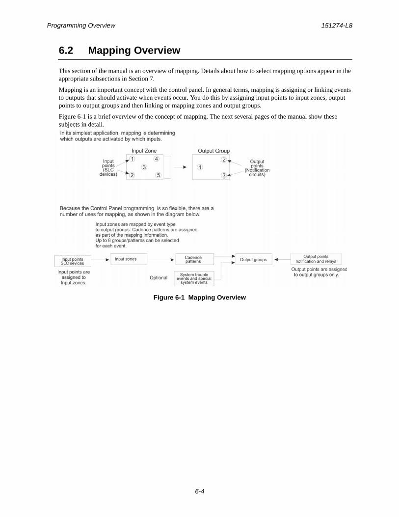
Programming Overview 151274-L8
6-4
6.2 Mapping Overview
This section of the manual is an overview of mapping. Details about how to select mapping options appear in the appropriate subsections in Section 7.
Mapping is an important concept with the control panel. In general terms, mapping is assigning or linking events to outputs that should activate when events occur. You do this by assigning input points to input zones, output points to output groups and then linking or mapping zones and output groups.
Figure 6-1 is a brief overview of the concept of mapping. The next several pages of the manual show these subjects in detail.
Figure 6-1 Mapping Overview
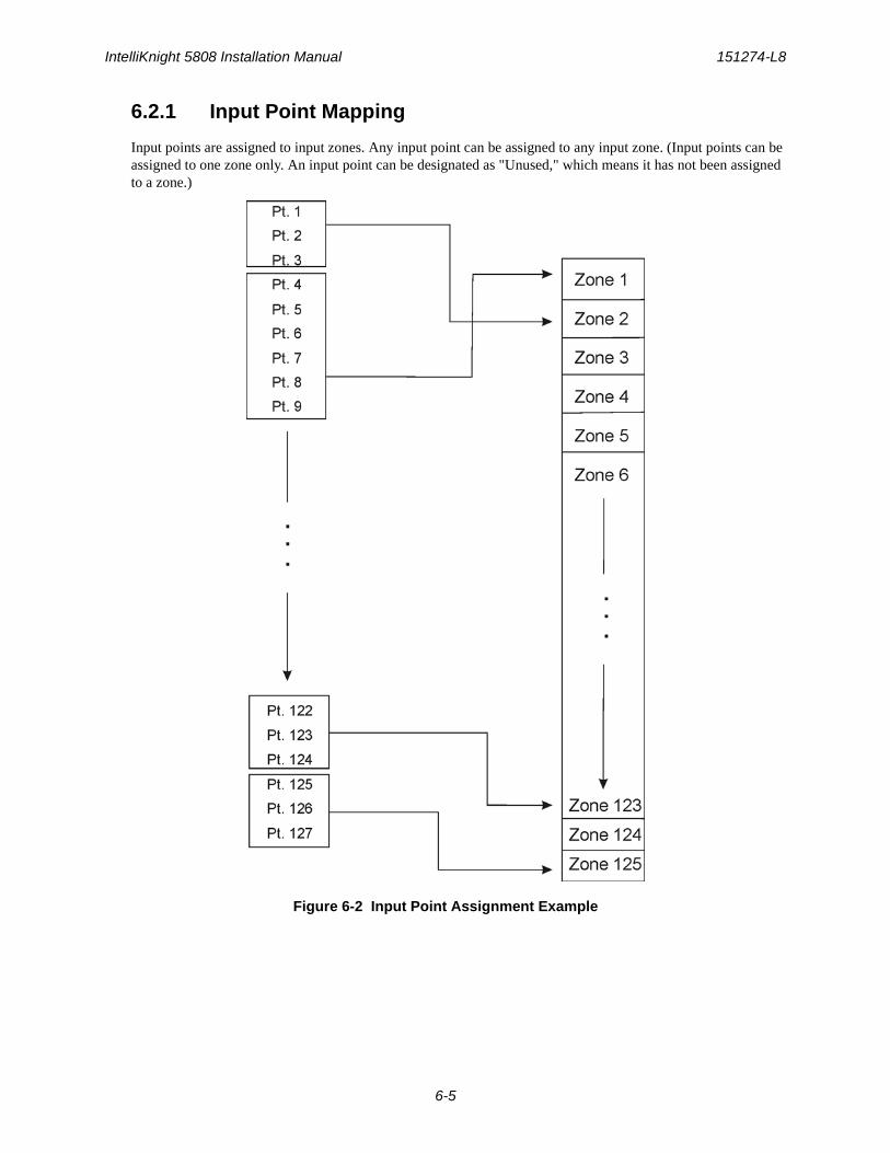
IntelliKnight 5808 Installation Manual 151274-L8
6-5
6.2.1 Input Point Mapping
Input points are assigned to input zones. Any input point can be assigned to any input zone. (Input points can be assigned to one zone only. An input point can be designated as "Unused," which means it has not been assigned to a zone.)
Figure 6-2 Input Point Assignment Example
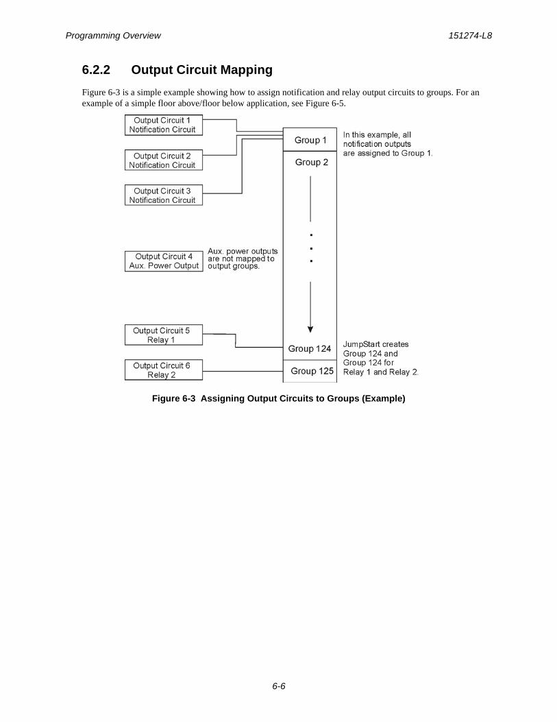
Programming Overview 151274-L8
6-6
6.2.2 Output Circuit Mapping
Figure 6-3 is a simple example showing how to assign notification and relay output circuits to groups. For an example of a simple floor above/floor below application, see Figure 6-5.
Figure 6-3 Assigning Output Circuits to Groups (Example)
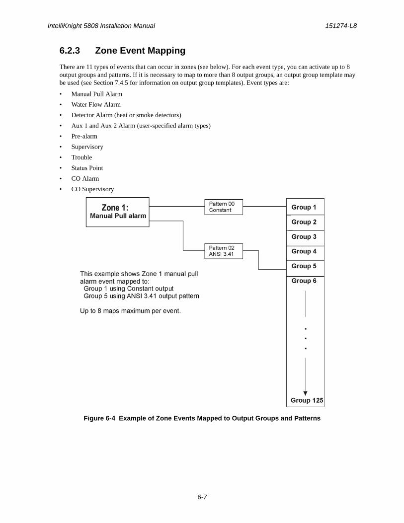
IntelliKnight 5808 Installation Manual 151274-L8
6-7
6.2.3 Zone Event Mapping
There are 11 types of events that can occur in zones (see below). For each event type, you can activate up to 8 output groups and patterns. If it is necessary to map to more than 8 output groups, an output group template may be used (see Section 7.4.5 for information on output group templates). Event types are:
• Manual Pull Alarm
• Water Flow Alarm
• Detector Alarm (heat or smoke detectors)
• Aux 1 and Aux 2 Alarm (user-specified alarm types)
• Pre-alarm
• Supervisory
• Trouble
• Status Point
• CO Alarm
• CO Supervisory
Figure 6-4 Example of Zone Events Mapped to Output Groups and Patterns
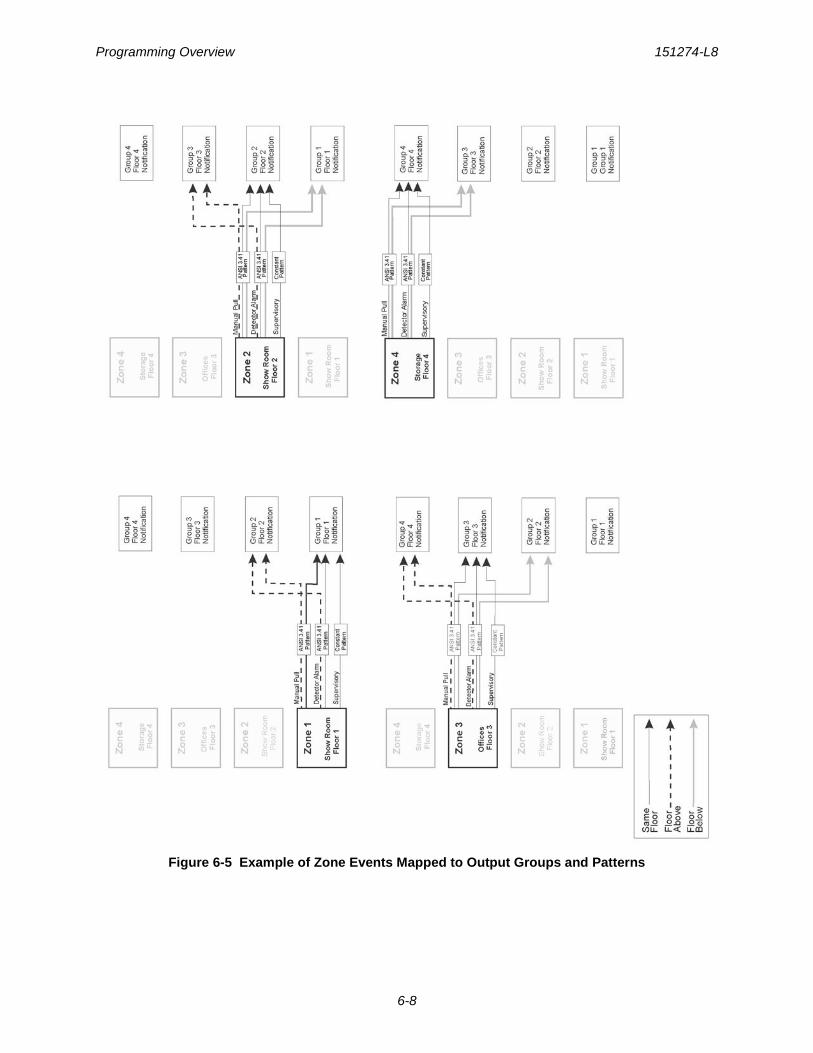
Programming Overview 151274-L8
6-8
Figure 6-5 Example of Zone Events Mapped to Output Groups and Patterns
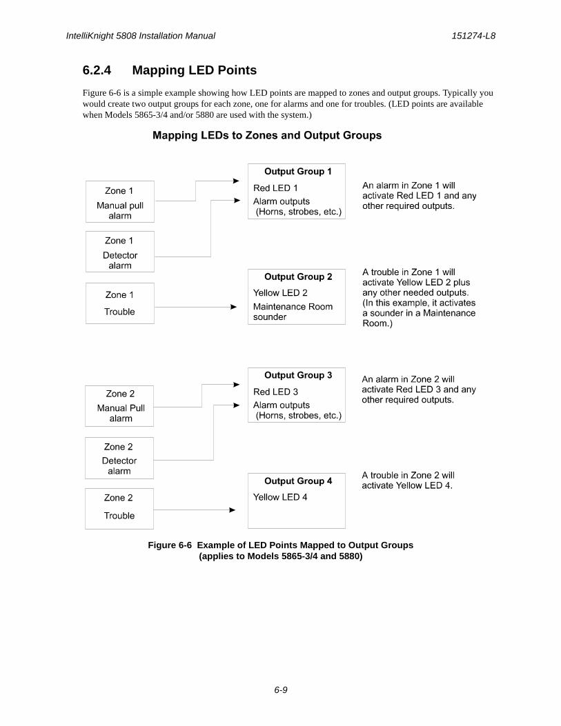
IntelliKnight 5808 Installation Manual 151274-L8
6-9
6.2.4 Mapping LED Points
Figure 6-6 is a simple example showing how LED points are mapped to zones and output groups. Typically you would create two output groups for each zone, one for alarms and one for troubles. (LED points are available when Models 5865-3/4 and/or 5880 are used with the system.)
Figure 6-6 Example of LED Points Mapped to Output Groups(applies to Models 5865-3/4 and 5880)

Programming Overview 151274-L8
6-10
6.3 Programming Using the 5660 Silent Knight Software Suite
You can use the 5660 Silent Knight Software Suite (SKSS) to program the control panel onsite or remotely. SKSS is an optional software package that lets you easily program the control panel using a Windows-based computer and a modem* (not sold by Silent Knight). When using SKSS, you can set up the programming options for the panel, save the options in a file, then download the file to the panel. You connect to the control panel directly using the control panel’s onboard USB or serial port or remotely using a modem. If you need to connect to an older control panel that does not have a USB port, and your laptop does not have a serial port, use a USB to serial converter. SKSS includes an Online help system and a manual. See the SKSS manual (PN 151240) for more information.
* See Section 1.3 for a list of modems that have been tested for compatibility with the control panel and SKSS.
6.4 Programming Using an Annunciator
You can program the control panel from a system annunciator, using either the control panel’s on-board annunciator or a remote annunciator.
The following subsections describe programming basics, including a description of editing keys available for programming and how to move through programming menus. Section 7 contains specific information about individual programming options.
6.4.1 Entering / Exiting the Programming Menu
To enter the Programming Menu: 1. Enter the Installer Code (factory programmed default code is 123456).
2. The display prompts you to press the or ENTER key to bring up the Main Menu (see Figure 6-7).
Figure 6-7 Keypad Enabled Screen
3. Press 7. The menus described in Section 7 of this manual will display. Section 6.5 of this manual is a quick reference listing all programmable options and JumpStart defaults.
To exit the programming menu:When you have completed working with the menus, press the left arrow several times until you are exited from programming mode. Two prompts will display. The first prompt is to make sure you intended to leave the Program Menu (select Yes or No as appropriate). The second prompt is for accepting all changes. If you select No, any changes you have made since you entered the Program Menu will have no effect.
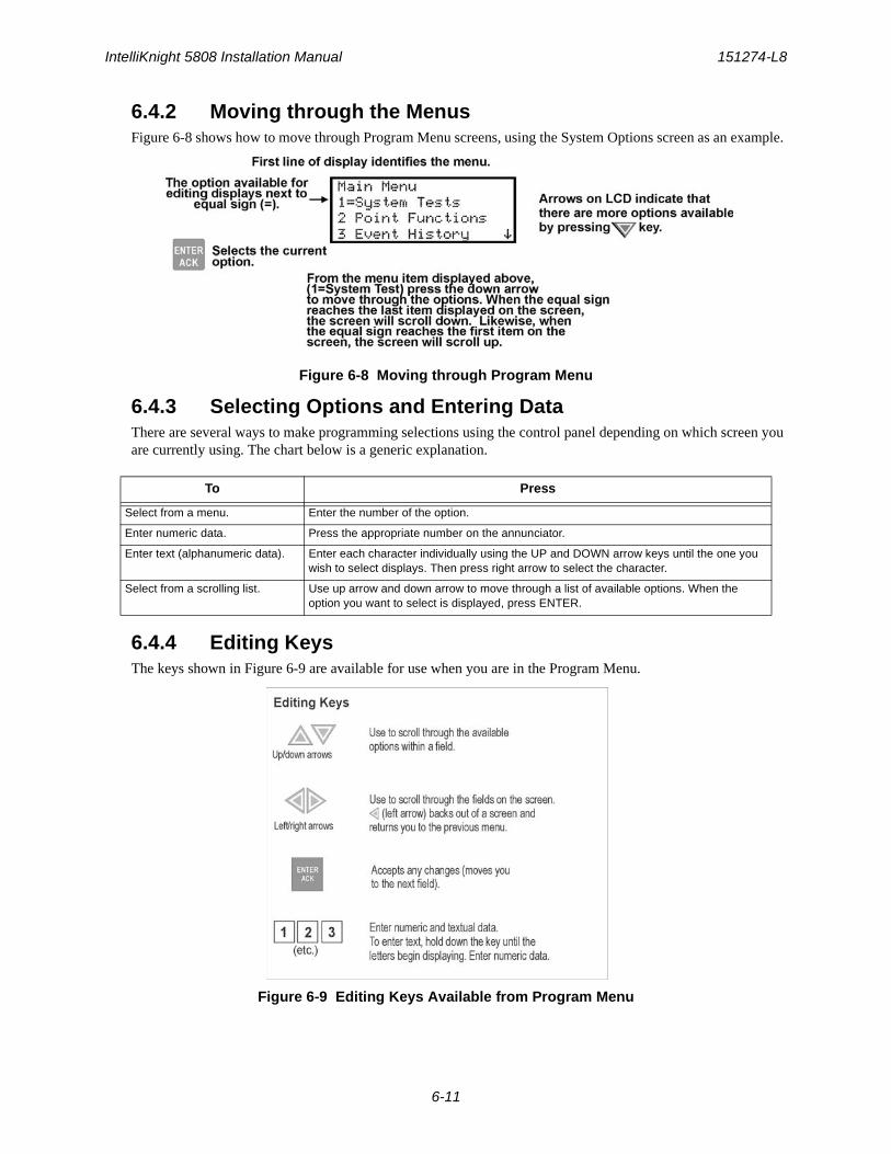
IntelliKnight 5808 Installation Manual 151274-L8
6-11
6.4.2 Moving through the MenusFigure 6-8 shows how to move through Program Menu screens, using the System Options screen as an example.
Figure 6-8 Moving through Program Menu
6.4.3 Selecting Options and Entering DataThere are several ways to make programming selections using the control panel depending on which screen you are currently using. The chart below is a generic explanation.
6.4.4 Editing KeysThe keys shown in Figure 6-9 are available for use when you are in the Program Menu.
Figure 6-9 Editing Keys Available from Program Menu
To Press
Select from a menu. Enter the number of the option.
Enter numeric data. Press the appropriate number on the annunciator.
Enter text (alphanumeric data). Enter each character individually using the UP and DOWN arrow keys until the one you wish to select displays. Then press right arrow to select the character.
Select from a scrolling list. Use up arrow and down arrow to move through a list of available options. When the option you want to select is displayed, press ENTER.
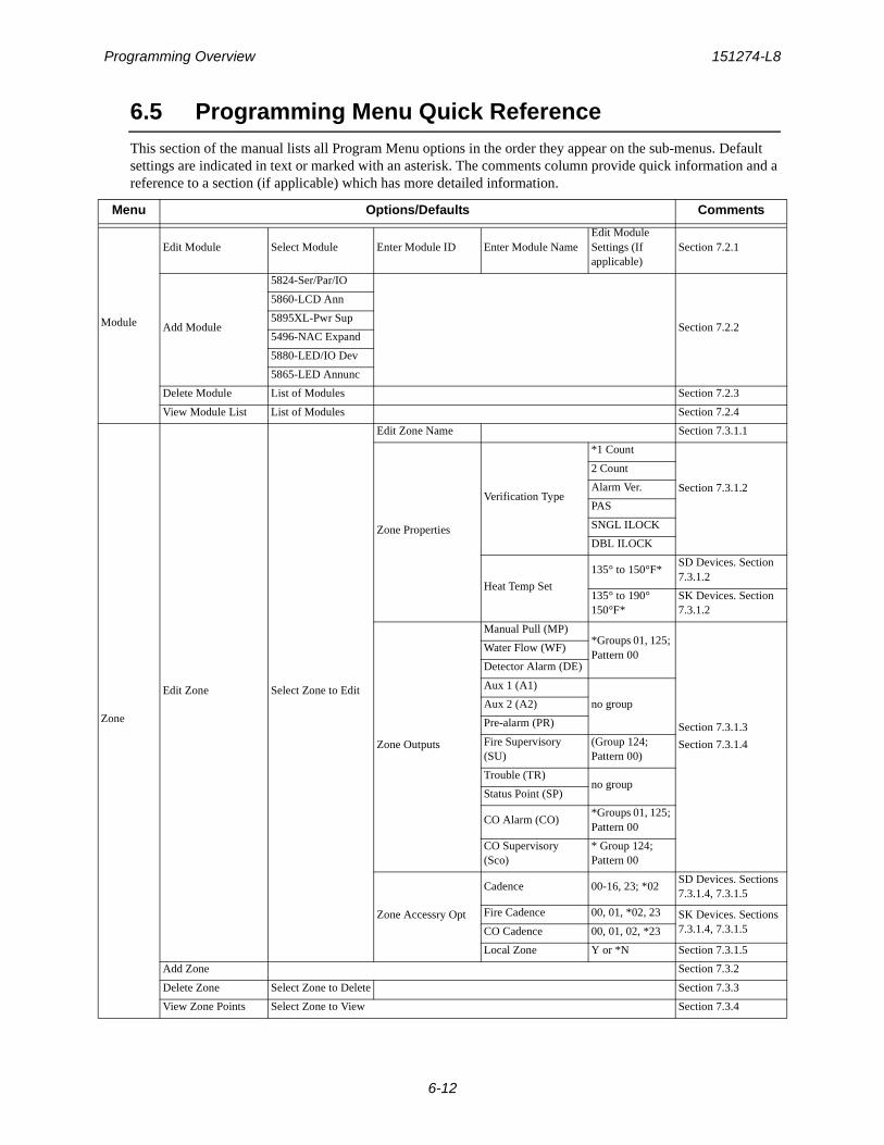
Programming Overview 151274-L8
6-12
6.5 Programming Menu Quick ReferenceThis section of the manual lists all Program Menu options in the order they appear on the sub-menus. Default settings are indicated in text or marked with an asterisk. The comments column provide quick information and a reference to a section (if applicable) which has more detailed information.
Menu Options/Defaults Comments
Module
Edit Module Select Module Enter Module ID Enter Module NameEdit Module Settings (If applicable)
Section 7.2.1
Add Module
5824-Ser/Par/IO
Section 7.2.2
5860-LCD Ann
5895XL-Pwr Sup
5496-NAC Expand
5880-LED/IO Dev
5865-LED Annunc
Delete Module List of Modules Section 7.2.3
View Module List List of Modules Section 7.2.4
Zone
Edit Zone Select Zone to Edit
Edit Zone Name Section 7.3.1.1
Zone Properties
Verification Type
*1 Count
Section 7.3.1.2
2 Count
Alarm Ver.
PAS
SNGL ILOCK
DBL ILOCK
Heat Temp Set
135° to 150°F*SD Devices. Section 7.3.1.2
135° to 190° 150°F*
SK Devices. Section 7.3.1.2
Zone Outputs
Manual Pull (MP)*Groups 01, 125; Pattern 00
Section 7.3.1.3
Section 7.3.1.4
Water Flow (WF)
Detector Alarm (DE)
Aux 1 (A1)
no groupAux 2 (A2)
Pre-alarm (PR)
Fire Supervisory (SU)
(Group 124; Pattern 00)
Trouble (TR)no group
Status Point (SP)
CO Alarm (CO)*Groups 01, 125; Pattern 00
CO Supervisory (Sco)
* Group 124; Pattern 00
Zone Accessry Opt
Cadence 00-16, 23; *02SD Devices. Sections 7.3.1.4, 7.3.1.5
Fire Cadence 00, 01, *02, 23 SK Devices. Sections 7.3.1.4, 7.3.1.5CO Cadence 00, 01, 02, *23
Local Zone Y or *N Section 7.3.1.5
Add Zone Section 7.3.2
Delete Zone Select Zone to Delete Section 7.3.3
View Zone Points Select Zone to View Section 7.3.4
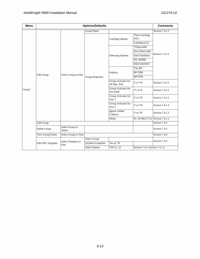
IntelliKnight 5808 Installation Manual 151274-L8
6-13
Group1
Edit Group Select Group to Edit
Group Name Section 7.4.1.1
Group Properties
Latching Options
*Non-Latching (NL)
Section 7.4.1.2
Latching (LA)
Silencing Options
*Silenceable
Non-Silenceable
Auto Unsilence
SIL-INHIB
SHUT-DOWN
Polarity
*No RP
RP-TRB
RP-NTR
Group Activates for all Man. Pull
Y or *N Section 7.4.1.2
Group Activates for Fire Drill
*Y or N Section 7.4.1.2
Group Activates for Aux 1
Y or *N Section 7.4.1.2
Group Activates for Aux 2
Y or *N Section 7.4.1.2
Ignore Global Cadence
Y or *N Section 7.4.1.2
Delay 05 -60 Min (*15) Section 7.4.1.2
Add Group Section 7.4.2
Delete GroupSelect Group to Delete
Section 7.4.3
View Group Points Select Group to View Section 7.4.4
Edit OPG TemplateSelect Template to Edit
Select GroupSection 7.4.5
Include in template Yes or *N
Select Pattern *00-21, 23 Section 7.4.5, Section 7.3.1.4
Menu Options/Defaults Comments
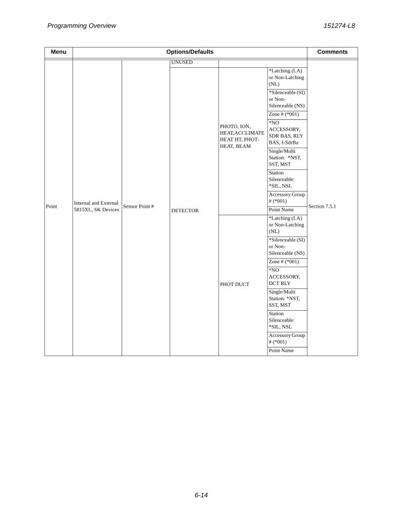
Programming Overview 151274-L8
6-14
PointInternal and External 5815XL, SK Devices
Sensor Point #
UNUSED
Section 7.5.1DETECTOR
PHOTO, ION, HEAT,ACCLIMATEHEAT HT, PHOT-HEAT, BEAM
*Latching (LA) or Non-Latching (NL)
*Silenceable (SI) or Non-Silenceable (NS)
Zone # (*001)
*NO ACCESSORY, SDR BAS, RLY BAS, I-SdrBa
Single/Multi Station: *NST, SST, MST
Station Silenceable: *SIL, NSL
Accessory Group # (*001)
Point Name
PHOT DUCT
*Latching (LA) or Non-Latching (NL)
*Silenceable (SI) or Non-Silenceable (NS)
Zone # (*001)
*NO ACCESSORY, DCT RLY
Single/Multi Station: *NST, SST, MST
Station Silenceable: *SIL, NSL
Accessory Group # (*001)
Point Name
Menu Options/Defaults Comments
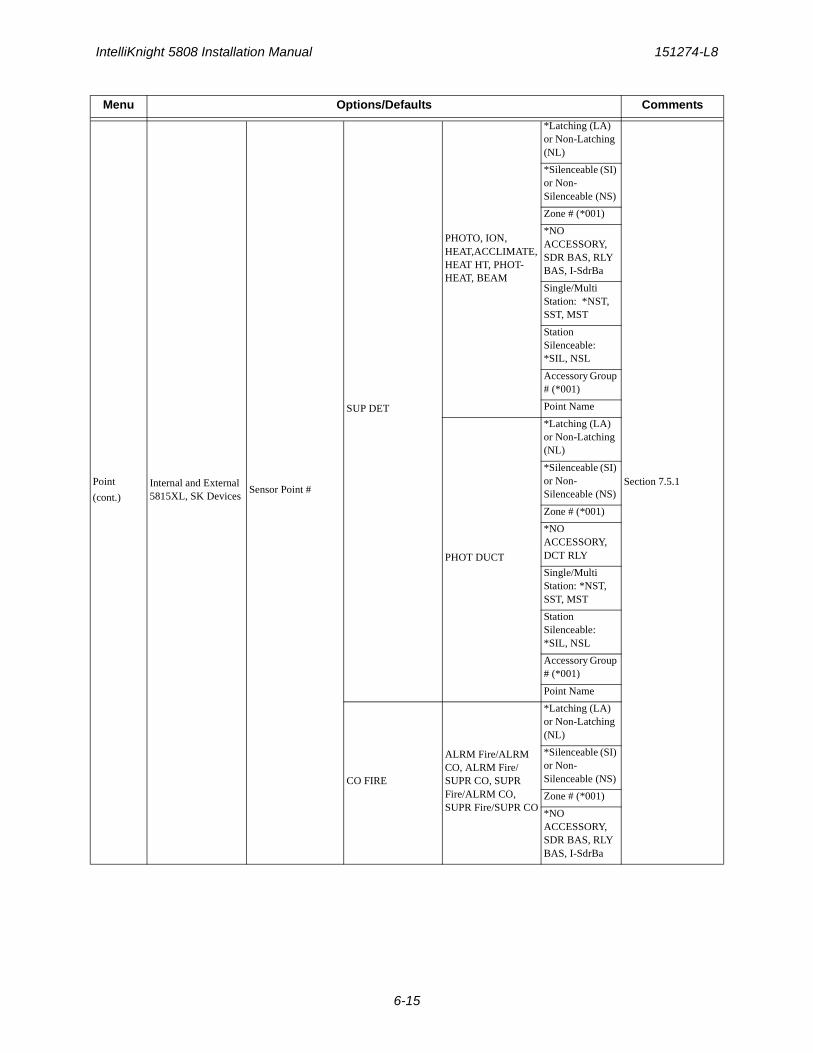
IntelliKnight 5808 Installation Manual 151274-L8
6-15
Point
(cont.)Internal and External 5815XL, SK Devices
Sensor Point #
SUP DET
PHOTO, ION, HEAT,ACCLIMATE, HEAT HT, PHOT-HEAT, BEAM
*Latching (LA) or Non-Latching (NL)
Section 7.5.1
*Silenceable (SI) or Non-Silenceable (NS)
Zone # (*001)
*NO ACCESSORY, SDR BAS, RLY BAS, I-SdrBa
Single/Multi Station: *NST, SST, MST
Station Silenceable: *SIL, NSL
Accessory Group # (*001)
Point Name
PHOT DUCT
*Latching (LA) or Non-Latching (NL)
*Silenceable (SI) or Non-Silenceable (NS)
Zone # (*001)
*NO ACCESSORY, DCT RLY
Single/Multi Station: *NST, SST, MST
Station Silenceable: *SIL, NSL
Accessory Group # (*001)
Point Name
CO FIRE
ALRM Fire/ALRM CO, ALRM Fire/SUPR CO, SUPR Fire/ALRM CO, SUPR Fire/SUPR CO
*Latching (LA) or Non-Latching (NL)
*Silenceable (SI) or Non-Silenceable (NS)
Zone # (*001)
*NO ACCESSORY, SDR BAS, RLY BAS, I-SdrBa
Menu Options/Defaults Comments
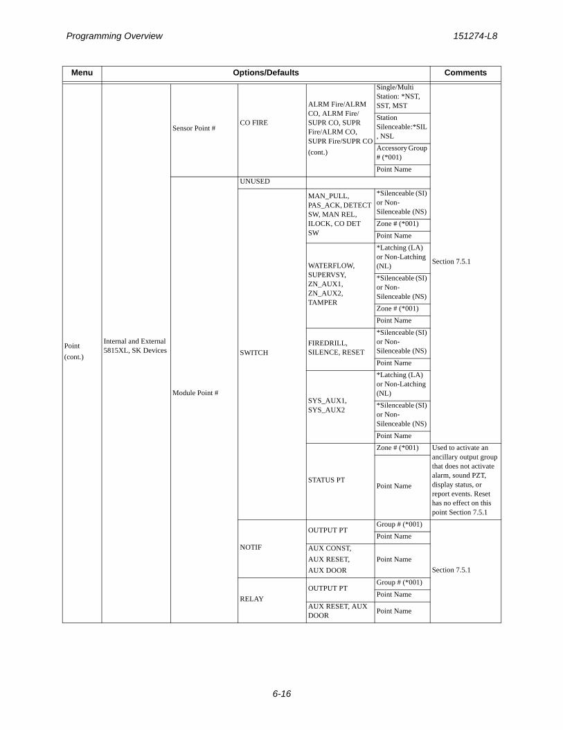
Programming Overview 151274-L8
6-16
Point
(cont.)
Internal and External 5815XL, SK Devices
Sensor Point #CO FIRE
ALRM Fire/ALRM CO, ALRM Fire/SUPR CO, SUPR Fire/ALRM CO, SUPR Fire/SUPR CO
(cont.)
Single/Multi Station: *NST, SST, MST
Section 7.5.1
Station Silenceable:*SIL, NSL
Accessory Group # (*001)
Point Name
Module Point #
UNUSED
SWITCH
MAN_PULL, PAS_ACK, DETECT SW, MAN REL, ILOCK, CO DET SW
*Silenceable (SI) or Non-Silenceable (NS)
Zone # (*001)
Point Name
WATERFLOW, SUPERVSY, ZN_AUX1, ZN_AUX2, TAMPER
*Latching (LA) or Non-Latching (NL)
*Silenceable (SI) or Non-Silenceable (NS)
Zone # (*001)
Point Name
FIREDRILL, SILENCE, RESET
*Silenceable (SI) or Non-Silenceable (NS)
Point Name
SYS_AUX1, SYS_AUX2
*Latching (LA) or Non-Latching (NL)
*Silenceable (SI) or Non-Silenceable (NS)
Point Name
STATUS PT
Zone # (*001) Used to activate an ancillary output group that does not activate alarm, sound PZT, display status, or report events. Reset has no effect on this point Section 7.5.1
Point Name
NOTIF
OUTPUT PTGroup # (*001)
Section 7.5.1
Point Name
AUX CONST,
AUX RESET,
AUX DOOR
Point Name
RELAY
OUTPUT PTGroup # (*001)
Point Name
AUX RESET, AUX DOOR
Point Name
Menu Options/Defaults Comments
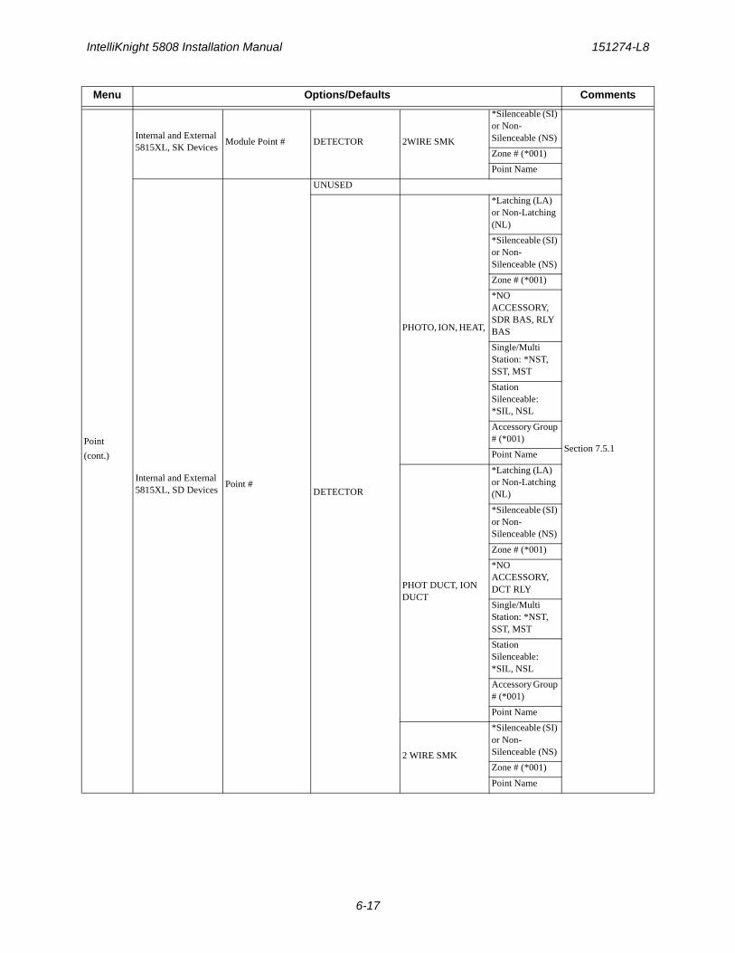
IntelliKnight 5808 Installation Manual 151274-L8
6-17
Point
(cont.)
Internal and External 5815XL, SK Devices
Module Point # DETECTOR 2WIRE SMK
*Silenceable (SI) or Non-Silenceable (NS)
Section 7.5.1
Zone # (*001)
Point Name
Internal and External 5815XL, SD Devices
Point #
UNUSED
DETECTOR
PHOTO, ION, HEAT,
*Latching (LA) or Non-Latching (NL)
*Silenceable (SI) or Non-Silenceable (NS)
Zone # (*001)
*NO ACCESSORY, SDR BAS, RLY BAS
Single/Multi Station: *NST, SST, MST
Station Silenceable: *SIL, NSL
Accessory Group # (*001)
Point Name
PHOT DUCT, ION DUCT
*Latching (LA) or Non-Latching (NL)
*Silenceable (SI) or Non-Silenceable (NS)
Zone # (*001)
*NO ACCESSORY, DCT RLY
Single/Multi Station: *NST, SST, MST
Station Silenceable: *SIL, NSL
Accessory Group # (*001)
Point Name
2 WIRE SMK
*Silenceable (SI) or Non-Silenceable (NS)
Zone # (*001)
Point Name
Menu Options/Defaults Comments
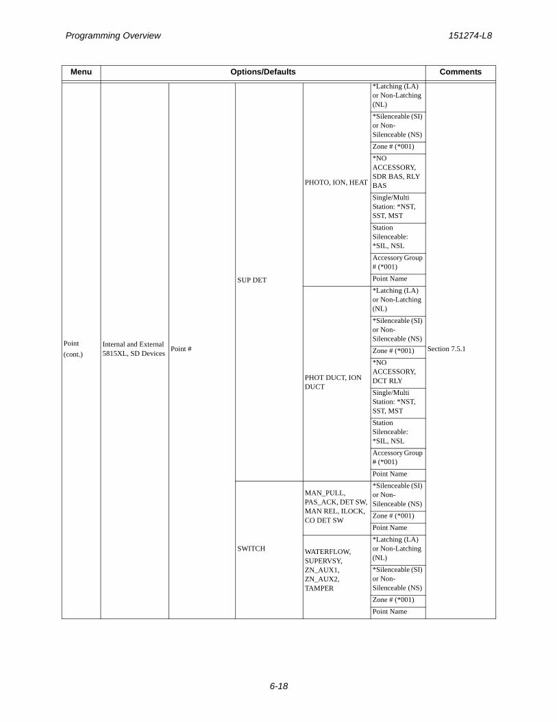
Programming Overview 151274-L8
6-18
Point
(cont.)Internal and External 5815XL, SD Devices
Point #
SUP DET
PHOTO, ION, HEAT
*Latching (LA) or Non-Latching (NL)
Section 7.5.1
*Silenceable (SI) or Non-Silenceable (NS)
Zone # (*001)
*NO ACCESSORY, SDR BAS, RLY BAS
Single/Multi Station: *NST, SST, MST
Station Silenceable: *SIL, NSL
Accessory Group # (*001)
Point Name
PHOT DUCT, ION DUCT
*Latching (LA) or Non-Latching (NL)
*Silenceable (SI) or Non-Silenceable (NS)
Zone # (*001)
*NO ACCESSORY, DCT RLY
Single/Multi Station: *NST, SST, MST
Station Silenceable: *SIL, NSL
Accessory Group # (*001)
Point Name
SWITCH
MAN_PULL, PAS_ACK, DET SW, MAN REL, ILOCK, CO DET SW
*Silenceable (SI) or Non-Silenceable (NS)
Zone # (*001)
Point Name
WATERFLOW, SUPERVSY, ZN_AUX1, ZN_AUX2, TAMPER
*Latching (LA) or Non-Latching (NL)
*Silenceable (SI) or Non-Silenceable (NS)
Zone # (*001)
Point Name
Menu Options/Defaults Comments
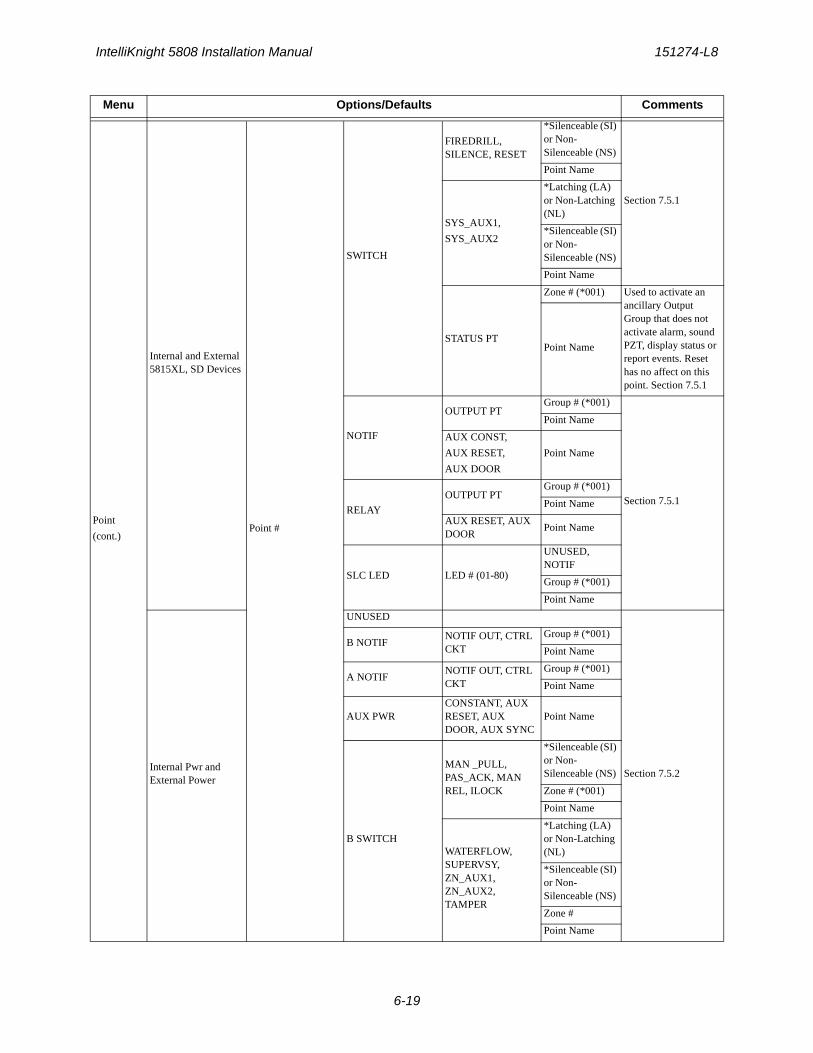
IntelliKnight 5808 Installation Manual 151274-L8
6-19
Point
(cont.)
Internal and External 5815XL, SD Devices
Point #
SWITCH
FIREDRILL, SILENCE, RESET
*Silenceable (SI) or Non-Silenceable (NS)
Section 7.5.1
Point Name
SYS_AUX1,
SYS_AUX2
*Latching (LA) or Non-Latching (NL)
*Silenceable (SI) or Non-Silenceable (NS)
Point Name
STATUS PT
Zone # (*001) Used to activate an ancillary Output Group that does not activate alarm, sound PZT, display status or report events. Reset has no affect on this point. Section 7.5.1
Point Name
NOTIF
OUTPUT PTGroup # (*001)
Section 7.5.1
Point Name
AUX CONST,
AUX RESET,
AUX DOOR
Point Name
RELAY
OUTPUT PTGroup # (*001)
Point Name
AUX RESET, AUX DOOR
Point Name
SLC LED LED # (01-80)
UNUSED, NOTIF
Group # (*001)
Point Name
Internal Pwr and External Power
UNUSED
Section 7.5.2
B NOTIFNOTIF OUT, CTRL CKT
Group # (*001)
Point Name
A NOTIFNOTIF OUT, CTRL CKT
Group # (*001)
Point Name
AUX PWRCONSTANT, AUX RESET, AUX DOOR, AUX SYNC
Point Name
B SWITCH
MAN _PULL, PAS_ACK, MAN REL, ILOCK
*Silenceable (SI) or Non-Silenceable (NS)
Zone # (*001)
Point Name
WATERFLOW, SUPERVSY, ZN_AUX1, ZN_AUX2, TAMPER
*Latching (LA) or Non-Latching (NL)
*Silenceable (SI) or Non-Silenceable (NS)
Zone #
Point Name
Menu Options/Defaults Comments
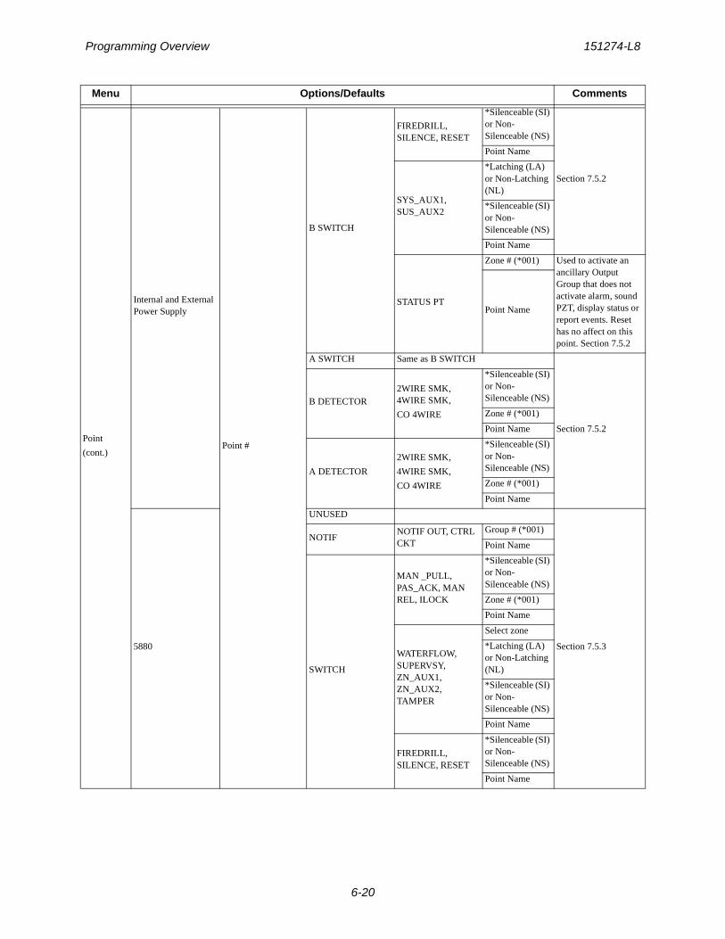
Programming Overview 151274-L8
6-20
Point
(cont.)
Internal and External Power Supply
Point #
B SWITCH
FIREDRILL, SILENCE, RESET
*Silenceable (SI) or Non-Silenceable (NS)
Section 7.5.2
Point Name
SYS_AUX1, SUS_AUX2
*Latching (LA) or Non-Latching (NL)
*Silenceable (SI) or Non-Silenceable (NS)
Point Name
STATUS PT
Zone # (*001) Used to activate an ancillary Output Group that does not activate alarm, sound PZT, display status or report events. Reset has no affect on this point. Section 7.5.2
Point Name
A SWITCH Same as B SWITCH
Section 7.5.2
B DETECTOR2WIRE SMK, 4WIRE SMK,
CO 4WIRE
*Silenceable (SI) or Non-Silenceable (NS)
Zone # (*001)
Point Name
A DETECTOR
2WIRE SMK,
4WIRE SMK,
CO 4WIRE
*Silenceable (SI) or Non-Silenceable (NS)
Zone # (*001)
Point Name
5880
UNUSED
Section 7.5.3
NOTIFNOTIF OUT, CTRL CKT
Group # (*001)
Point Name
SWITCH
MAN _PULL, PAS_ACK, MAN REL, ILOCK
*Silenceable (SI) or Non-Silenceable (NS)
Zone # (*001)
Point Name
WATERFLOW, SUPERVSY, ZN_AUX1, ZN_AUX2, TAMPER
Select zone
*Latching (LA) or Non-Latching (NL)
*Silenceable (SI) or Non-Silenceable (NS)
Point Name
FIREDRILL, SILENCE, RESET
*Silenceable (SI) or Non-Silenceable (NS)
Point Name
Menu Options/Defaults Comments
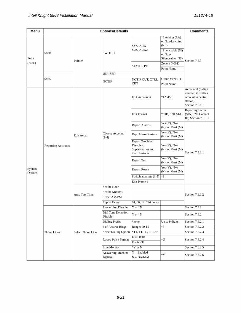
IntelliKnight 5808 Installation Manual 151274-L8
6-21
Point
(cont.)
5880
Point #
SWITCH
SYS_AUX1, SUS_AUX2
*Latching (LA) or Non-Latching (NL)
Section 7.5.3
*Silenceable (SI) or Non-Silenceable (NS)
STATUS PTZone # (*001)
Point Name
5865
UNUSED
NOTIFNOTIF OUT, CTRL CKT
Group # (*001)
Point Name
System Options
Reporting Accounts
Edit Acct.Choose Account (1-4)
Edit Account # *123456
Account # (6-digit number, identifies account to central station)Section 7.6.1.1
Edit Format *CID, S20, SIAReporting Format (SIA, S20, Contact ID) Section 7.6.1.1
Report AlarmsYes (Y), *No (N), or Must (M)
Section 7.6.1.1
Rep. Alarm RestoreYes (Y), *No (N), or Must (M)
Report Troubles, Disables, Supervisories and their Restores
Yes (Y), *No (N), or Must (M)
Report TestYes (Y), *No (N), or Must (M)
Report ResetsYes (Y), *No (N), or Must (M)
Switch attempts (1-5) *3
Edit Phone #
Auto Test Time
Set the Hour
Section 7.6.1.2Set the Minutes
Select AM/PM
Report Every 04, 06, 12, *24 hours
Phone Lines Select Phone Line
Phone Line Disable Y or *N Section 7.6.2
Dial Tone Detection Disable
Y or *N Section 7.6.2
Dialing Prefix *none Up to 9 digits Section 7.6.2.1
# of Answer Rings Range: 00-15 *6 Section 7.6.2.2
Select Dialing Option *TT, TT/PL, PULSE Section 7.6.2.3
Rotary Pulse Format U = 60/40
*U Section 7.6.2.4E = 66/34
Line Monitor *Y or N Section 7.6.2.5
Answering Machine Bypass
Y = Enabled
N = Disabled*Y Section 7.6.2.6
Menu Options/Defaults Comments
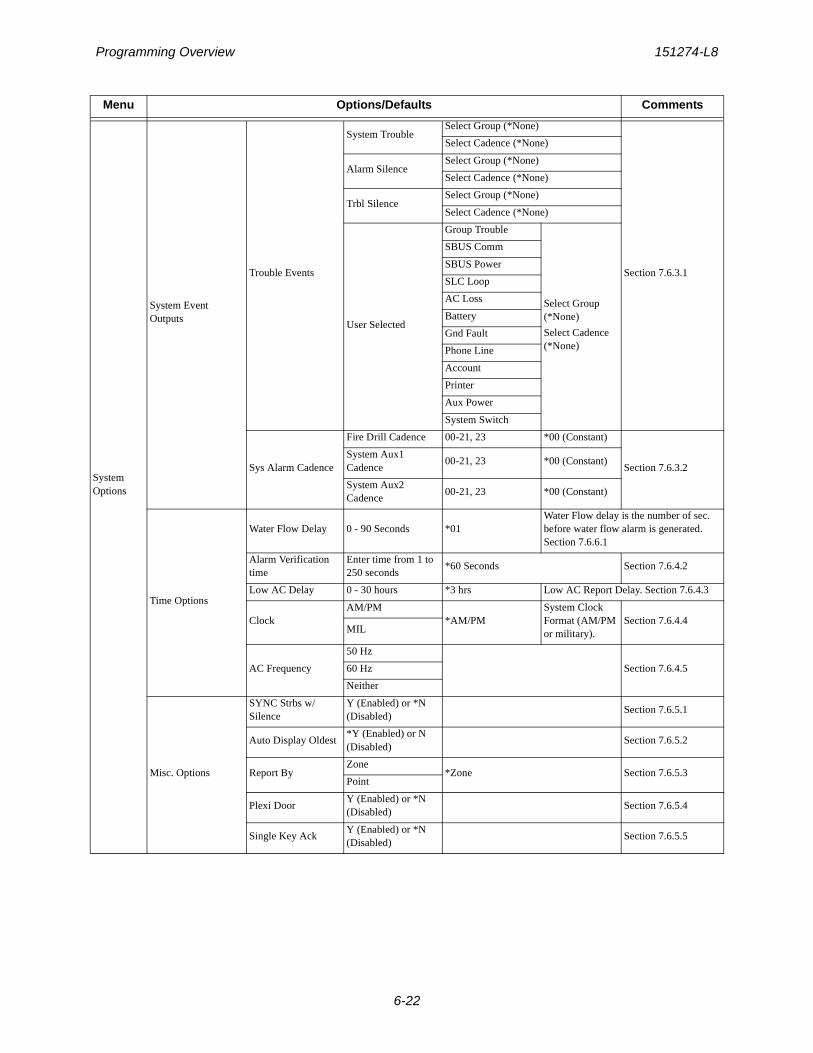
Programming Overview 151274-L8
6-22
System Options
System Event Outputs
Trouble Events
System TroubleSelect Group (*None)
Section 7.6.3.1
Select Cadence (*None)
Alarm SilenceSelect Group (*None)
Select Cadence (*None)
Trbl SilenceSelect Group (*None)
Select Cadence (*None)
User Selected
Group Trouble
Select Group (*None)
Select Cadence (*None)
SBUS Comm
SBUS Power
SLC Loop
AC Loss
Battery
Gnd Fault
Phone Line
Account
Printer
Aux Power
System Switch
Sys Alarm Cadence
Fire Drill Cadence 00-21, 23 *00 (Constant)
Section 7.6.3.2System Aux1 Cadence
00-21, 23 *00 (Constant)
System Aux2 Cadence
00-21, 23 *00 (Constant)
Time Options
Water Flow Delay 0 - 90 Seconds *01Water Flow delay is the number of sec. before water flow alarm is generated. Section 7.6.6.1
Alarm Verification time
Enter time from 1 to 250 seconds
*60 Seconds Section 7.6.4.2
Low AC Delay 0 - 30 hours *3 hrs Low AC Report Delay. Section 7.6.4.3
ClockAM/PM
*AM/PMSystem Clock Format (AM/PM or military).
Section 7.6.4.4MIL
AC Frequency
50 Hz
Section 7.6.4.560 Hz
Neither
Misc. Options
SYNC Strbs w/ Silence
Y (Enabled) or *N (Disabled)
Section 7.6.5.1
Auto Display Oldest*Y (Enabled) or N (Disabled)
Section 7.6.5.2
Report ByZone
*Zone Section 7.6.5.3Point
Plexi DoorY (Enabled) or *N (Disabled)
Section 7.6.5.4
Single Key AckY (Enabled) or *N (Disabled)
Section 7.6.5.5
Menu Options/Defaults Comments
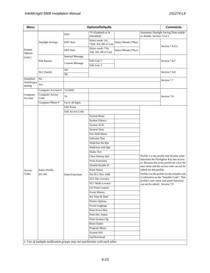
IntelliKnight 5808 Installation Manual 151274-L8
6-23
System Options
(cont.)
Daylight Savings
DST*Y (Enabled) or N (Disabled)
Automatic Daylight Saving Time enable or disable. Section 7.6.6.1
DST StartSelect week: 1st, *2nd, 3rd, 4th or Last
Select Month (*Mar)
Section 7.6.6.2
DST EndSelect week: *1st, 2nd, 3rd, 4th or Last
Select Month (*Nov)
Edit Banner
Internal Message
Section 7.6.7Custom Message
Edit Line 1
Edit Line 2
SLC FamilySD
Section 7.6.8SK
JumpStart AutoProgramming
No Section 7.7
Yes
Computer Account
Computer Account # *123456
Section 7.8Computer Access Code
*0
Computer Phone # Up to 40 digits
Access Codes
Select Profile
(01-20)
Edit Name
Profile 1 is the profile that dictates what functions the Firefighter Key has access to. Because this is the profile for a key the user name and the access code can not be edited for this profile.
Profile 2 is the profile for the installer and is referred to as the “Installer Code”. This profile’s user name and panel functions can not be edited.. Section 7.9
Edit Access Code
Panel Functions
System Reset
System Silence
System ACK
System Tests
Fire Drill Menu
Indicator Test
WalkTest-No Rpt
WalkTest-with Rpt
Dialer Test
Clear History Buf
Point Functions
Disable/Enable Pt
Point Status
Set SLC Dev Addr
SLC Dev Locator
SLC Multi Locator
I/O Point Control
Event History
Set Time & Date
Printer Options
Event Loggings
Print Event Hist.
Print Det. Status
Print System Cfg
Reset Dialer
Program Menu
System Info
Up/Download
1. Use of multiple notification groups may not synchronize with each other.
Menu Options/Defaults Comments
151274-L8
7-1
Section 7Programming
This section of the manual describes how to manually program the control panel from the built-in annunciator. Each subsection discusses these menu options in detail. All options described in this section can be performed using the Silent Knight Software Suite 5660.
7.1 UL 864 Programming Requirements
7.2 Modules
This section lists the options available under the module option in the program menu. The following modules are available for the control panel: 5860 remote fire alarm annunciator, 5824 serial/parallel printer interface module, 5496 intelligent power module, 5880 LED I/O module, and 5865 LED annunciator.
Important!
Before any customized programming is done, Jump-start should be run first. After Jump-start is run, thoroughly test the system. The reason the system should be tested after Jump-start is because Jump-start automatically programs the system, searching for and configuring all SLC and SBUS devices it finds. Jump-start allows you to confirm the integrity of the installation prior to performing any custom programming. After determining that the hardware is properly installed, custom programming can be performed. Refer to Section 6.
NOTICE TO USERS, INSTALLERS, AUTHORITIES HAVING JURISDICTION, AND OTHER INVOLVED PARTIES: This product incorporates field programmable software. In order for the product to comply with the requirements in the Standard for Control Units and Accessories for Fire Alarm Systems, UL 864, certain programming features or options must be limited to specific values or not used at all as indicated below.
Programming Option Menu ItemPermitted inUL 864 (Y/N)
Possible Settings
Settings Permitted in
UL 864
Time Options Low AC Report Delay
Yes 0–30 hours 1–3
Display Oldest EventY (Enabled) Yes Yes & No Yes
N (Disabled) No Yes & No No
Alarm Verification Alarm Verification
Yes 1-250 1-60
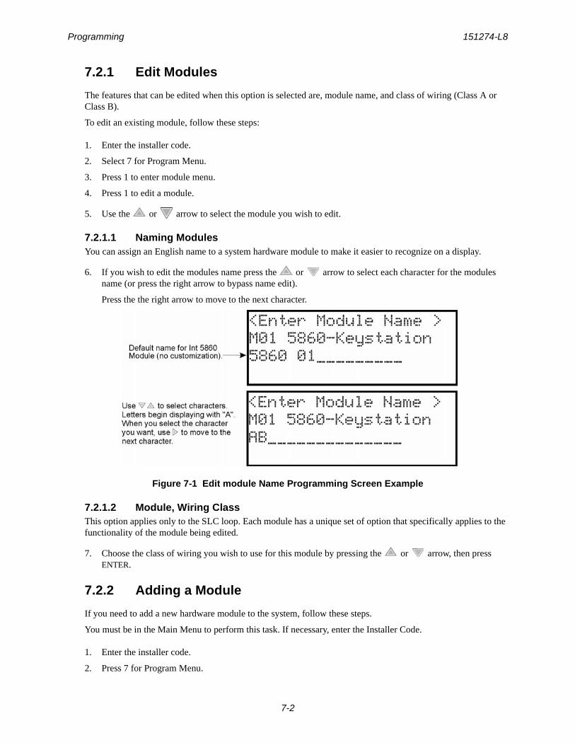
Programming 151274-L8
7-2
7.2.1 Edit Modules
The features that can be edited when this option is selected are, module name, and class of wiring (Class A or Class B).
To edit an existing module, follow these steps:
1. Enter the installer code.
2. Select 7 for Program Menu.
3. Press 1 to enter module menu.
4. Press 1 to edit a module.
5. Use the or arrow to select the module you wish to edit.
7.2.1.1 Naming ModulesYou can assign an English name to a system hardware module to make it easier to recognize on a display.
6. If you wish to edit the modules name press the or arrow to select each character for the modules name (or press the right arrow to bypass name edit).
Press the the right arrow to move to the next character.
Figure 7-1 Edit module Name Programming Screen Example
7.2.1.2 Module, Wiring ClassThis option applies only to the SLC loop. Each module has a unique set of option that specifically applies to the functionality of the module being edited.
7. Choose the class of wiring you wish to use for this module by pressing the or arrow, then press ENTER.
7.2.2 Adding a Module
If you need to add a new hardware module to the system, follow these steps.
You must be in the Main Menu to perform this task. If necessary, enter the Installer Code.
1. Enter the installer code.
2. Press 7 for Program Menu.
IntelliKnight 5808 Installation Manual 151274-L8
7-3
3. Press 1 to enter module menu.
4. Press 2 to add a module.
5. From the next screen, use the or arrow to choose a module type to add from the <New Module Type> screen.
The screen will display “Adding module [#]...” for a few moments. You will be returned to the <New Mod-ule Type> screen where you can add additional modules if desired.
You must save changes when you exit the Program Menu or the new module will not be added.
Note: If you Add a Module that has not been physically connected, the panel will go into trouble after it reinitializes (when you exit the Program Menu). When the new module is attached, the trouble will correct itself automatically the next time you power up the system.
7.2.3 Deleting a Module
If you ever need to delete a module, follow these steps.
You must be in the Main Menu to perform this task. If necessary, enter the Installer Code.
1. Enter the installer code.
2. Press 7 for Program Menu.
3. Press 1 to enter module menu.
4. Press 3 to delete a module.
5. From the next screen, select a module to delete.
6. A warning screen will display. If you want to proceed with deleting the module, select Yes. To cancel, select No.
7.2.4 View Module List
1. Enter the installer code.
2. Press 7 for Program Menu.
3. Press 1 to enter module menu.
4. Press 4 to view module list.
7.3 Zone
Through the zone option in the program menu you can edit, add, delete, and view zone points. Selections made here affect all detectors and switches in the zone. Up to 125 zones can be used in the system.
7.3.1 Edit Zone
Features that can be edited through the edit zone option are zone name, zone properties (which includes, zone type, and detector sensitivity), zone output mapping, and zone accessory options.
To edit a zone, follow these steps:
1. Enter the installer code.
2. Press 7 for Program Menu.
3. Press 2 to enter zone menu.
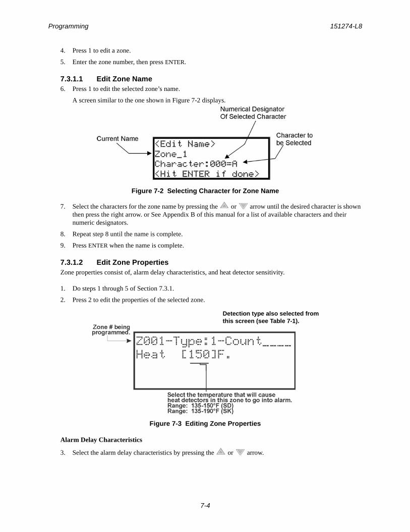
Programming 151274-L8
7-4
4. Press 1 to edit a zone.
5. Enter the zone number, then press ENTER.
7.3.1.1 Edit Zone Name6. Press 1 to edit the selected zone’s name.
A screen similar to the one shown in Figure 7-2 displays.
Figure 7-2 Selecting Character for Zone Name
7. Select the characters for the zone name by pressing the or arrow until the desired character is shown then press the right arrow. or See Appendix B of this manual for a list of available characters and their numeric designators.
8. Repeat step 8 until the name is complete.
9. Press ENTER when the name is complete.
7.3.1.2 Edit Zone PropertiesZone properties consist of, alarm delay characteristics, and heat detector sensitivity.
1. Do steps 1 through 5 of Section 7.3.1.
2. Press 2 to edit the properties of the selected zone.
Figure 7-3 Editing Zone Properties
Alarm Delay Characteristics
3. Select the alarm delay characteristics by pressing the or arrow.
Detection type also selected from this screen (see Table 7-1).

IntelliKnight 5808 Installation Manual 151274-L8
7-5
Table 7-1 list the delay choices and a description of each.
4. Press ENTER.
Heat Temperature SettingUse this feature to set the temperature at which high temperature detectors will respond. All detectors in the zone will respond in the same way. The range for the SD505-AHS heat detector is from 135°F to 150°F. The range for SK-Heat-HT heat detector is from 135°F to 190°F.
The SD505-AHS and SK-Heat-HT heat detectors are absolute temperature devices. This means that they respond to an alarm immediately if the temperature in the zone goes above the programmed temperature.
5. Enter the temperature at which the heat detector will respond, or use the or keys to scroll through the range or enter directly from the number keys on the annunciator, then press ENTER.
6. Use the or keys to scroll through the range.
7. Then press ENTER.
Table 7-1: Alarm Delay Characteristics
Type of Delay Description
1-Count One Count (No Delay). When this option is enabled, an alarm occurs immediately when a single device of any of the following types goes into alarm: detector, manual pull, water flow, Aux1 or Aux2. This is considered the most typical operation and is the default for all zones.
2-Count When this type of alarm delay is used, two or more detectors within the zone must go into alarm in order for the zone to report an alarm. Switches of type manual pull, water flow, Aux1 and Aux2 are an exception; they will cause an alarm when only one switch is in alarm.
When a single detector is in alarm in a 2-Count zone, the system enters a prealarm condition. In a prealarm condition, the touchpad PZT beeps and the annunciator display indicates that a prealarm has occurred. If the zone has been mapped to an output group for the prealarm event, the output group will activate. The prealarm will not be reported to the central station.
Alarm Ver. Alarm verification is an optional false alarm prevention feature that verifies an alarm condition by resetting the smoke detector. If the alarm condition still exists by the time the reset cycle has completed, the detector will go into alarm. If the detector is no longer in alarm, no report will go to the central station. The alarm verification sequence is ignored if the zone is already in alarm.
PAS This option is intended to be used with an acknowledge switch. An alarm is delayed for 15 seconds, giving on-site personnel a chance to investigate the alarm. If the acknowledge switch is not activated within 15 seconds, an alarm occurs automatically.
If this option is enabled for a zone, the zone will respond to an alarm condition as follows:
• The zone will not go into alarm for 15 seconds to allow an on-site operator to activate the acknowledge switch.
• If the operator does not press the acknowledge switch within 15 seconds, the zone will go into alarm.
• If the operator presses the acknowledge switch within 15 seconds, a 180-sec-ond time-frame will begin counting down. This time-frame allows the operator to investigate the cause of the alarm.
If the operator performs a reset within 180 seconds, the alarm will not occur.
If the operator does not perform a reset within 180 seconds, an alarm will occur auto-matically.
• The P.A.S. feature will be overridden if another alarm occurs.
SNGL ILOCK See Section 8.7.1 for single interlock releasing operation.
DBL ILOCK See Section 8.7.2 for double interlock releasing operation.
Note: SK-FIRE-CO and other CO detectors can only be installed in a 1 count zone; they will operate as a 1-count point regardless of the programmed zone type (i.e. Alarm Verification, 2 count, etc.).
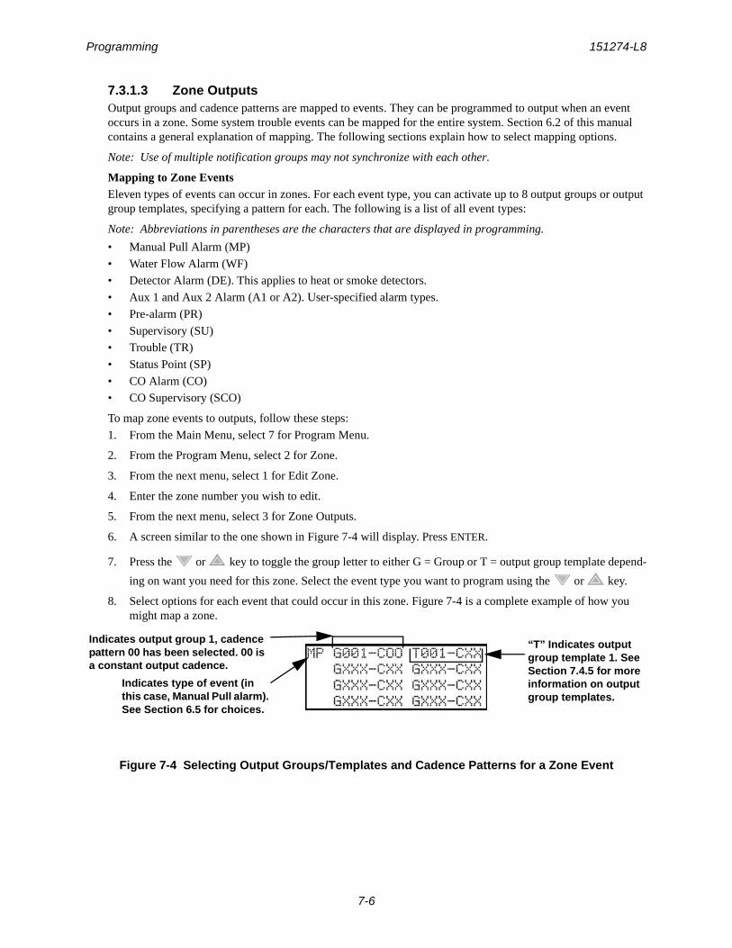
Programming 151274-L8
7-6
7.3.1.3 Zone OutputsOutput groups and cadence patterns are mapped to events. They can be programmed to output when an event occurs in a zone. Some system trouble events can be mapped for the entire system. Section 6.2 of this manual contains a general explanation of mapping. The following sections explain how to select mapping options.
Note: Use of multiple notification groups may not synchronize with each other.
Mapping to Zone EventsEleven types of events can occur in zones. For each event type, you can activate up to 8 output groups or output group templates, specifying a pattern for each. The following is a list of all event types:
Note: Abbreviations in parentheses are the characters that are displayed in programming.
• Manual Pull Alarm (MP)
• Water Flow Alarm (WF)
• Detector Alarm (DE). This applies to heat or smoke detectors.
• Aux 1 and Aux 2 Alarm (A1 or A2). User-specified alarm types.
• Pre-alarm (PR)
• Supervisory (SU)
• Trouble (TR)
• Status Point (SP)
• CO Alarm (CO)
• CO Supervisory (SCO)
To map zone events to outputs, follow these steps:
1. From the Main Menu, select 7 for Program Menu.
2. From the Program Menu, select 2 for Zone.
3. From the next menu, select 1 for Edit Zone.
4. Enter the zone number you wish to edit.
5. From the next menu, select 3 for Zone Outputs.
6. A screen similar to the one shown in Figure 7-4 will display. Press ENTER.
7. Press the or key to toggle the group letter to either G = Group or T = output group template depend-
ing on want you need for this zone. Select the event type you want to program using the or key.
8. Select options for each event that could occur in this zone. Figure 7-4 is a complete example of how you might map a zone.
Figure 7-4 Selecting Output Groups/Templates and Cadence Patterns for a Zone Event
Indicates type of event (in this case, Manual Pull alarm). See Section 6.5 for choices.
Indicates output group 1, cadence pattern 00 has been selected. 00 is a constant output cadence.
“T” Indicates output group template 1. See Section 7.4.5 for more information on output group templates.
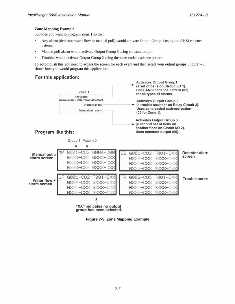
IntelliKnight 5808 Installation Manual 151274-L8
7-7
Zone Mapping ExampleSuppose you want to program Zone 1 so that:
• Any alarm (detector, water flow or manual pull) would activate Output Group 1 using the ANSI cadence pattern.
• Manual pull alarm would activate Output Group 3 using constant output.
• Troubles would activate Output Group 2 using the zone-coded cadence pattern.
To accomplish this you need to access the screen for each event and then select your output groups. Figure 7-5 shows how you would program this application.
Figure 7-5 Zone Mapping Example
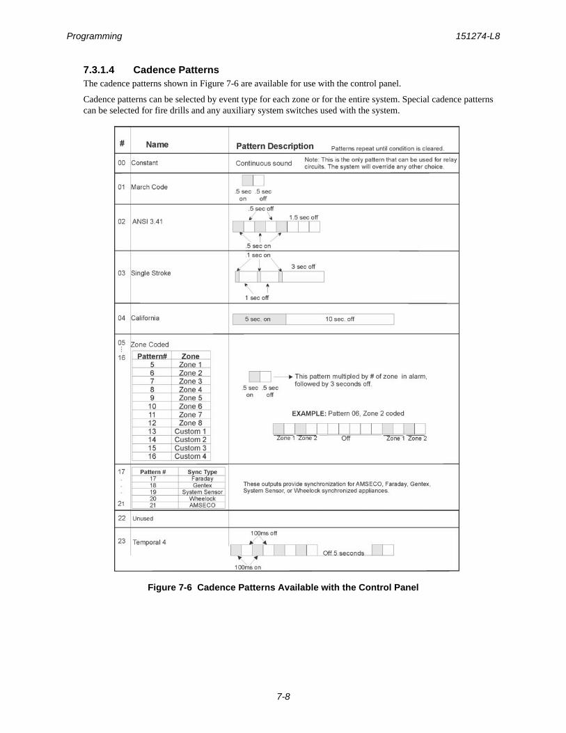
Programming 151274-L8
7-8
7.3.1.4 Cadence PatternsThe cadence patterns shown in Figure 7-6 are available for use with the control panel.
Cadence patterns can be selected by event type for each zone or for the entire system. Special cadence patterns can be selected for fire drills and any auxiliary system switches used with the system.
Figure 7-6 Cadence Patterns Available with the Control Panel
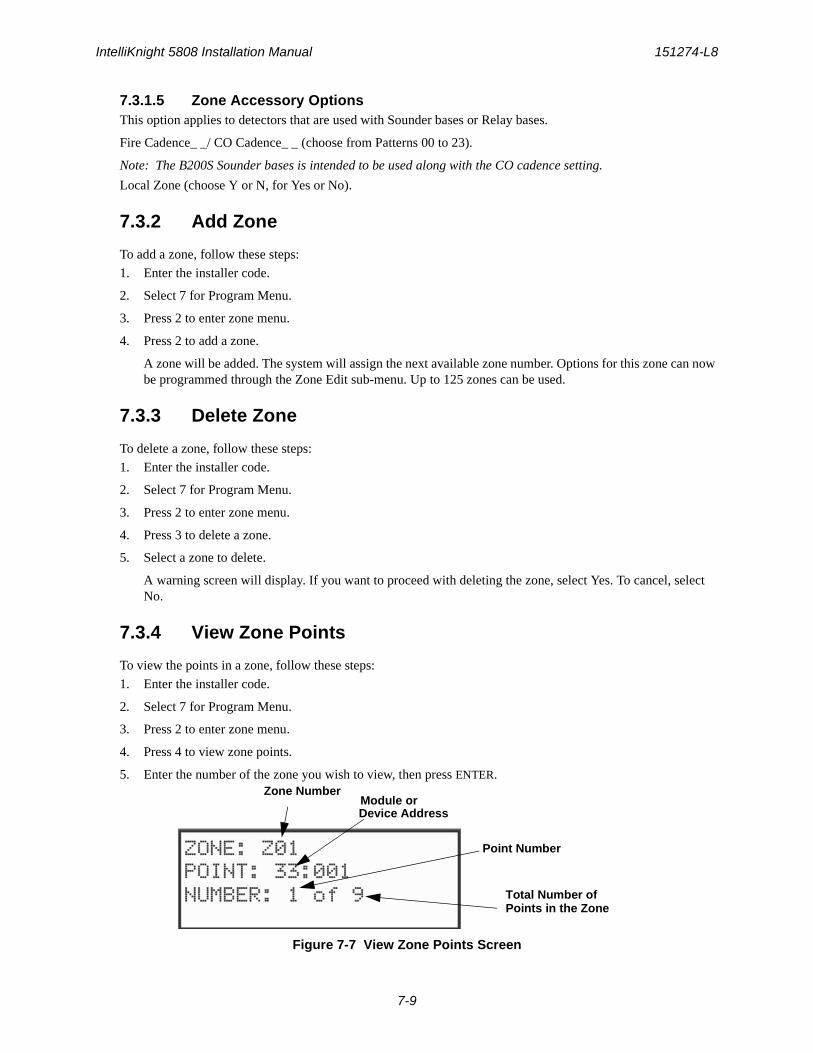
IntelliKnight 5808 Installation Manual 151274-L8
7-9
7.3.1.5 Zone Accessory OptionsThis option applies to detectors that are used with Sounder bases or Relay bases.
Fire Cadence_ _/ CO Cadence_ _ (choose from Patterns 00 to 23).
Note: The B200S Sounder bases is intended to be used along with the CO cadence setting.
Local Zone (choose Y or N, for Yes or No).
7.3.2 Add Zone
To add a zone, follow these steps:
1. Enter the installer code.
2. Select 7 for Program Menu.
3. Press 2 to enter zone menu.
4. Press 2 to add a zone.
A zone will be added. The system will assign the next available zone number. Options for this zone can now be programmed through the Zone Edit sub-menu. Up to 125 zones can be used.
7.3.3 Delete Zone
To delete a zone, follow these steps:
1. Enter the installer code.
2. Select 7 for Program Menu.
3. Press 2 to enter zone menu.
4. Press 3 to delete a zone.
5. Select a zone to delete.
A warning screen will display. If you want to proceed with deleting the zone, select Yes. To cancel, select No.
7.3.4 View Zone Points
To view the points in a zone, follow these steps:
1. Enter the installer code.
2. Select 7 for Program Menu.
3. Press 2 to enter zone menu.
4. Press 4 to view zone points.
5. Enter the number of the zone you wish to view, then press ENTER.
Figure 7-7 View Zone Points Screen
Zone NumberModule orDevice Address
Point Number
Total Number ofPoints in the Zone
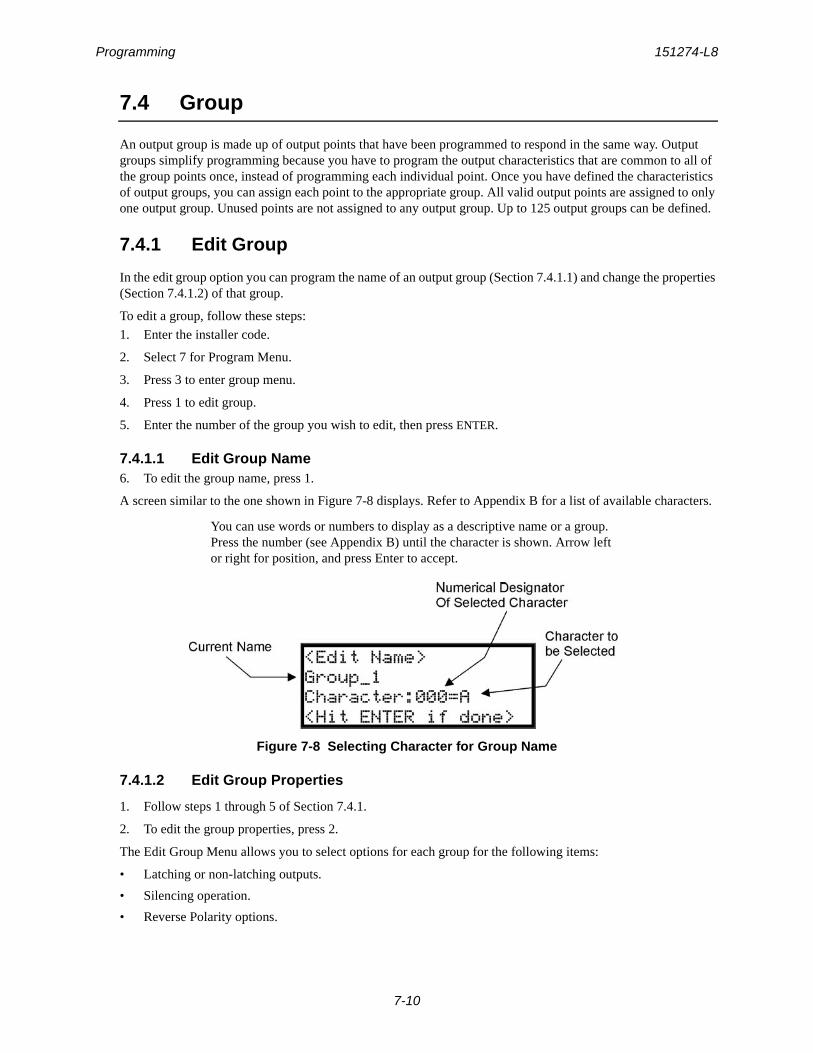
Programming 151274-L8
7-10
7.4 Group
An output group is made up of output points that have been programmed to respond in the same way. Output groups simplify programming because you have to program the output characteristics that are common to all of the group points once, instead of programming each individual point. Once you have defined the characteristics of output groups, you can assign each point to the appropriate group. All valid output points are assigned to only one output group. Unused points are not assigned to any output group. Up to 125 output groups can be defined.
7.4.1 Edit Group
In the edit group option you can program the name of an output group (Section 7.4.1.1) and change the properties (Section 7.4.1.2) of that group.
To edit a group, follow these steps:
1. Enter the installer code.
2. Select 7 for Program Menu.
3. Press 3 to enter group menu.
4. Press 1 to edit group.
5. Enter the number of the group you wish to edit, then press ENTER.
7.4.1.1 Edit Group Name6. To edit the group name, press 1.
A screen similar to the one shown in Figure 7-8 displays. Refer to Appendix B for a list of available characters.
Figure 7-8 Selecting Character for Group Name
7.4.1.2 Edit Group Properties
1. Follow steps 1 through 5 of Section 7.4.1.
2. To edit the group properties, press 2.
The Edit Group Menu allows you to select options for each group for the following items:
• Latching or non-latching outputs.
• Silencing operation.
• Reverse Polarity options.
You can use words or numbers to display as a descriptive name or a group. Press the number (see Appendix B) until the character is shown. Arrow left or right for position, and press Enter to accept.
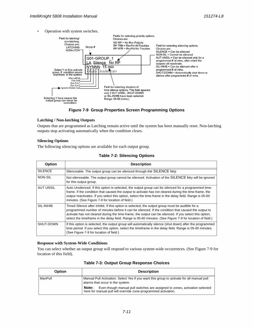
IntelliKnight 5808 Installation Manual 151274-L8
7-11
• Operation with system switches.
Figure 7-9 Group Properties Screen Programming Options
Latching / Non-latching OutputsOutputs that are programmed as Latching remain active until the system has been manually reset. Non-latching outputs stop activating automatically when the condition clears.
Silencing OptionsThe following silencing options are available for each output group.
Response with System-Wide ConditionsYou can select whether an output group will respond to various system-wide occurrences. (See Figure 7-9 for location of this field).
Table 7-2: Silencing Options
Option Description
SILENCE Silenceable. The output group can be silenced through the SILENCE key.
NON-SIL Not silenceable. The output group cannot be silenced. Activation of the SILENCE key will be ignored for this output group.
AUT UNSIL Auto Unsilenced. If this option is selected, the output group can be silenced for a programmed time-frame. If the condition that caused the output to activate has not cleared during the time-frame, the output reactivates. If you select this option, select the time-frame in the delay field. Range is 05-60 minutes. (See Figure 7-9 for location of field.)
SIL-INHIB Timed Silence after Inhibit. If this option is selected, the output group must be audible for a programmed number of minutes before it can be silenced. If the condition that caused the output to activate has not cleared during the time-frame, the output can be silenced. If you select this option, select the timeframe in the delay field. Range is 05-60 minutes. (See Figure 7-9 for location of field.)
SHUT-DOWN If this option is selected, the output group will automatically silence (shut down) after the programmed time period. If you select this option, select the timeframe in the delay field. Range is 05-60 minutes. (See Figure 7-9 for location of field.)
Table 7-3: Output Group Response Choices
Option Description
ManPull Manual Pull Activation. Select Yes if you want this group to activate for all manual pull alarms that occur in the system.
Note: Even though manual pull switches are assigned to zones, activation selected here for manual pull will override zone-programmed activation.
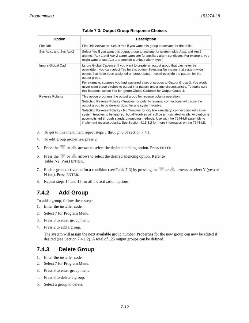
Programming 151274-L8
7-12
3. To get to this menu item repeat steps 1 through 6 of section 7.4.1.
4. To edit group properties, press 2.
5. Press the or arrows to select the desired latching option. Press ENTER.
6. Press the or arrows to select the desired silencing option. Refer toTable 7-2. Press ENTER.
7. Enable group activation for a condition (see Table 7-3) by pressing the or arrows to select Y (yes) or N (no). Press ENTER.
8. Repeat steps 14 and 15 for all the activation options.
7.4.2 Add GroupTo add a group, follow these steps:
1. Enter the installer code.
2. Select 7 for Program Menu.
3. Press 3 to enter group menu.
4. Press 2 to add a group.
The system will assign the next available group number. Properties for the new group can now be edited if desired (see Section 7.4.1.2). A total of 125 output groups can be defined.
7.4.3 Delete Group1. Enter the installer code.
2. Select 7 for Program Menu.
3. Press 3 to enter group menu.
4. Press 3 to delete a group.
5. Select a group to delete.
Fire Drill Fire Drill Activation. Select Yes if you want this group to activate for fire drills.
Sys Aux1 and Sys Aux2 Select Yes if you want this output group to activate for system-wide Aux1 and Aux2 alarms. (Aux 1 and Aux 2 alarm types are for auxiliary alarm conditions. For example, you might want to use Aux 1 to provide a unique alarm type.)
Ignore Global Cad Ignore Global Cadence. If you want to create an output group that can never be overridden, you can select Yes for this option. Selecting No means that system-wide events that have been assigned an output pattern could override the pattern for the output group.
For example, suppose you had assigned a set of strobes to Output Group 3. You would never want these strobes to output in a pattern under any circumstances. To make sure this happens, select Yes for Ignore Global Cadence for Output Group 3.
Reverse Polarity This option programs the output group for reverse polarity operation.
Selecting Reverse Polarity -Troubles for polarity reversal connections will cause the output group to be de-energized for any system trouble.
Selecting Reverse Polarity - No Troubles for city box (auxiliary) connections will cause system troubles to be ignored, but all troubles will still be annunciated locally. Activation is accomplished through standard mapping methods. Use with the 7644-L8 assembly to implement reverse polarity. See Section 4.13.3.2 for more information on the 7644-L8.
Table 7-3: Output Group Response Choices
Option Description
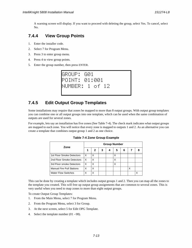
IntelliKnight 5808 Installation Manual 151274-L8
7-13
A warning screen will display. If you want to proceed with deleting the group, select Yes. To cancel, select No.
7.4.4 View Group Points
1. Enter the installer code.
2. Select 7 for Program Menu.
3. Press 3 to enter group menu.
4. Press 4 to view group points.
5. Enter the group number, then press ENTER.
7.4.5 Edit Output Group Templates
Some installations may require that zones be mapped to more than 8 output groups. With output group templates you can combine one or all output groups into one template, which can be used when the same combination of outputs are used for several zones.
For example, lets say an installation has five zones (See Table 7-4). The check mark indicates what output groups are mapped to each zone. You will notice that every zone is mapped to outputs 1 and 2. As an alternative you can create a template that combines output group 1 and 2 as one choice.
This can be done by creating a template which includes output groups 1 and 2. Then you can map all the zones to the template you created. This will free up output group assignments that are common to several zones. This is very useful when you need to map zones to more than eight output groups.
To create Output Group Templates:
1. From the Main Menu, select 7 for Program Menu.
2. From the Program Menu, select 3 for Group.
3. At the next screen, select 5 for Edit OPG Template.
4. Select the template number (01 - 08).
Table 7-4 Zone Group Example
ZoneGroup Number
1 2 3 4 5 6 7 8
1st Floor Smoke Detectors X X X
2nd Floor Smoke Detectors X X X
3rd Floor smoke Detectors X X X
Manual Fire Pull Stations X X X
Water Flow Switches X X X
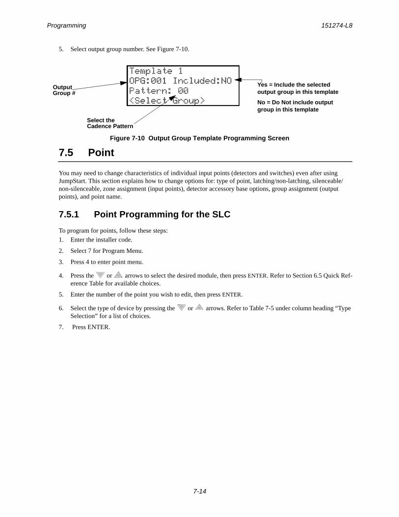
Programming 151274-L8
7-14
5. Select output group number. See Figure 7-10.
Figure 7-10 Output Group Template Programming Screen
7.5 Point
You may need to change characteristics of individual input points (detectors and switches) even after using JumpStart. This section explains how to change options for: type of point, latching/non-latching, silenceable/non-silenceable, zone assignment (input points), detector accessory base options, group assignment (output points), and point name.
7.5.1 Point Programming for the SLC
To program for points, follow these steps:
1. Enter the installer code.
2. Select 7 for Program Menu.
3. Press 4 to enter point menu.
4. Press the or arrows to select the desired module, then press ENTER. Refer to Section 6.5 Quick Ref-erence Table for available choices.
5. Enter the number of the point you wish to edit, then press ENTER.
6. Select the type of device by pressing the or arrows. Refer to Table 7-5 under column heading “Type Selection” for a list of choices.
7. Press ENTER.
OutputGroup #
Yes = Include the selected output group in this template
No = Do Not include output group in this template
Select theCadence Pattern
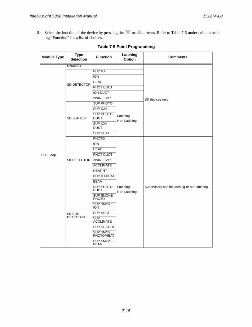
IntelliKnight 5808 Installation Manual 151274-L8
7-15
8. Select the function of the device by pressing the or arrows. Refer to Table 7-5 under column head-ing “Function” for a list of choices.
Table 7-5 Point Programming
Module TypeType
SelectionFunction
Latching Option
Comments
SLC Loop
UNUSED
SD devices only
SD DETECTOR
PHOTO
ION
HEAT
PHOT DUCT
ION DUCT
2WIRE SMK
SD SUP DET
SUP PHOTO
Latching
Non Latching
SUP ION
SUP PHOTO DUCT
SUP ION DUCT
SUP HEAT
SK DETECTOR
PHOTO
ION
HEAT
PHOT DUCT
2WIRE SMK
ACCLIMATE
HEAT HT
PHOTO-HEAT
BEAM
SK SUP DETECTOR
SUP PHOTO DUCT
Latching
Non Latching
Supervisory can be latching or non-latching.
SUP SMOKE PHOTO
SUP SMOKE ION
SUP HEAT
SUP ACCLIMATE
SUP HEAT HT
SUP SMOKE PHOTO/HEAT
SUP SMOKE BEAM
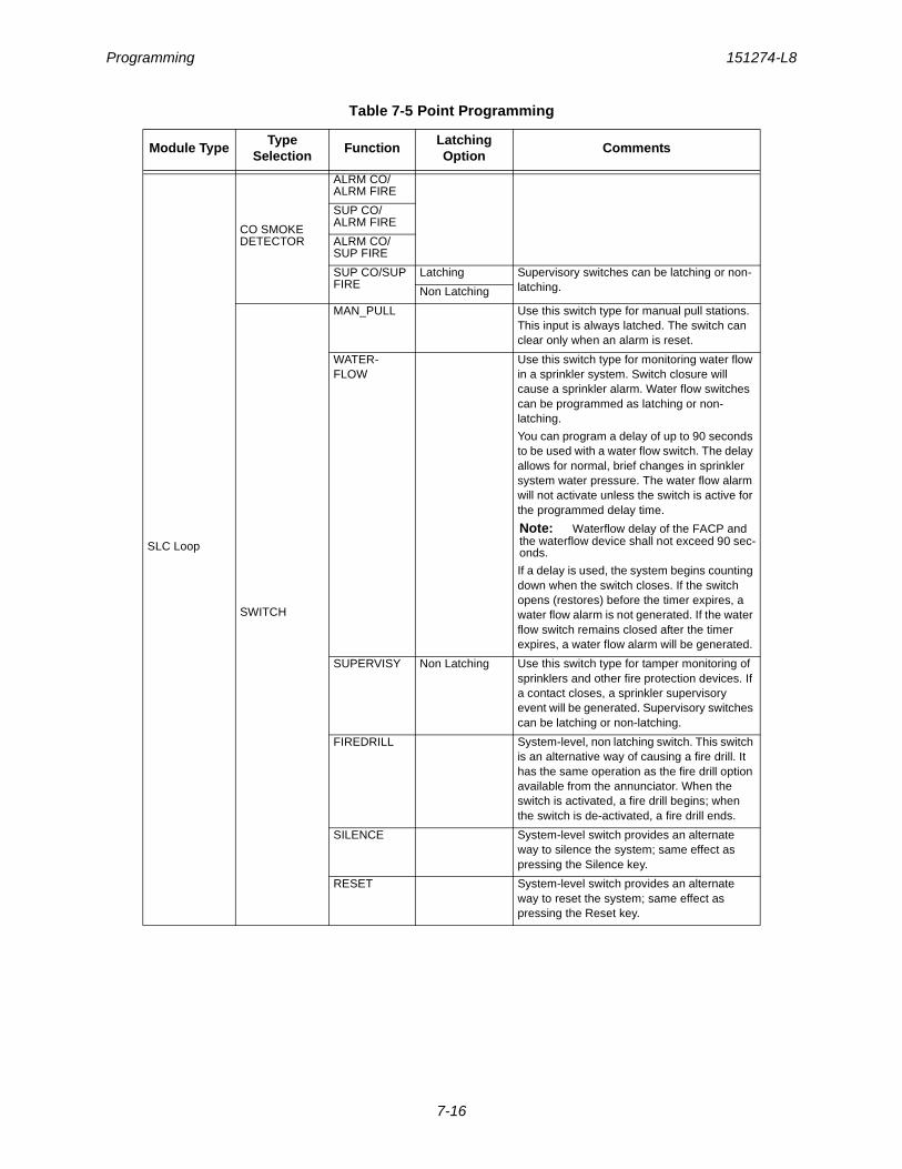
Programming 151274-L8
7-16
SLC Loop
CO SMOKE DETECTOR
ALRM CO/ALRM FIRE
SUP CO/ALRM FIRE
ALRM CO/SUP FIRE
SUP CO/SUP FIRE
Latching Supervisory switches can be latching or non-latching.Non Latching
SWITCH
MAN_PULL Use this switch type for manual pull stations. This input is always latched. The switch can clear only when an alarm is reset.
WATER-FLOW
Use this switch type for monitoring water flow in a sprinkler system. Switch closure will cause a sprinkler alarm. Water flow switches can be programmed as latching or non-latching.
You can program a delay of up to 90 seconds to be used with a water flow switch. The delay allows for normal, brief changes in sprinkler system water pressure. The water flow alarm will not activate unless the switch is active for the programmed delay time.
Note: Waterflow delay of the FACP and the waterflow device shall not exceed 90 sec-onds.
If a delay is used, the system begins counting down when the switch closes. If the switch opens (restores) before the timer expires, a water flow alarm is not generated. If the water flow switch remains closed after the timer expires, a water flow alarm will be generated.
SUPERVISY Non Latching Use this switch type for tamper monitoring of sprinklers and other fire protection devices. If a contact closes, a sprinkler supervisory event will be generated. Supervisory switches can be latching or non-latching.
FIREDRILL System-level, non latching switch. This switch is an alternative way of causing a fire drill. It has the same operation as the fire drill option available from the annunciator. When the switch is activated, a fire drill begins; when the switch is de-activated, a fire drill ends.
SILENCE System-level switch provides an alternate way to silence the system; same effect as pressing the Silence key.
RESET System-level switch provides an alternate way to reset the system; same effect as pressing the Reset key.
Table 7-5 Point Programming
Module TypeType
SelectionFunction
Latching Option
Comments
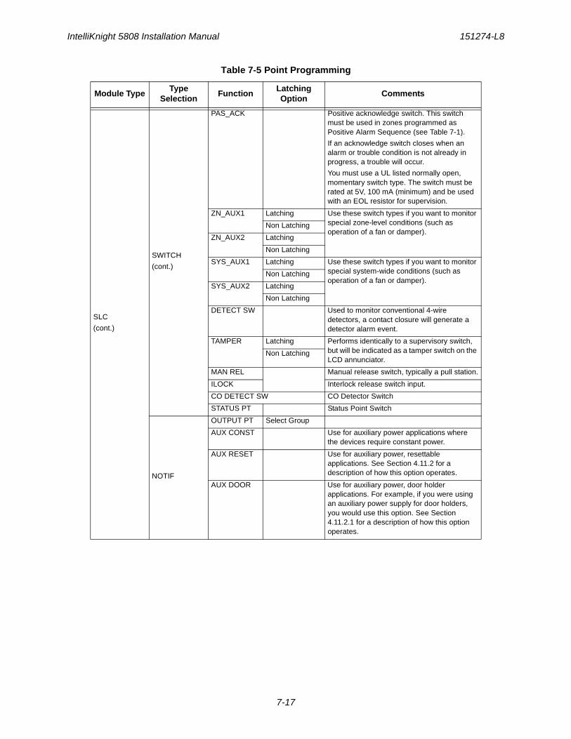
IntelliKnight 5808 Installation Manual 151274-L8
7-17
SLC
(cont.)
SWITCH
(cont.)
PAS_ACK Positive acknowledge switch. This switch must be used in zones programmed as Positive Alarm Sequence (see Table 7-1).
If an acknowledge switch closes when an alarm or trouble condition is not already in progress, a trouble will occur.
You must use a UL listed normally open, momentary switch type. The switch must be rated at 5V, 100 mA (minimum) and be used with an EOL resistor for supervision.
ZN_AUX1 Latching Use these switch types if you want to monitor special zone-level conditions (such as operation of a fan or damper).
Non Latching
ZN_AUX2 Latching
Non Latching
SYS_AUX1 Latching Use these switch types if you want to monitor special system-wide conditions (such as operation of a fan or damper).
Non Latching
SYS_AUX2 Latching
Non Latching
DETECT SW Used to monitor conventional 4-wire detectors, a contact closure will generate a detector alarm event.
TAMPER Latching Performs identically to a supervisory switch, but will be indicated as a tamper switch on the LCD annunciator.
Non Latching
MAN REL Manual release switch, typically a pull station.
ILOCK Interlock release switch input.
CO DETECT SW CO Detector Switch
STATUS PT Status Point Switch
NOTIF
OUTPUT PT Select Group
AUX CONST Use for auxiliary power applications where the devices require constant power.
AUX RESET Use for auxiliary power, resettable applications. See Section 4.11.2 for a description of how this option operates.
AUX DOOR Use for auxiliary power, door holder applications. For example, if you were using an auxiliary power supply for door holders, you would use this option. See Section 4.11.2.1 for a description of how this option operates.
Table 7-5 Point Programming
Module TypeType
SelectionFunction
Latching Option
Comments

Programming 151274-L8
7-18
7.5.2 Point Programming For Internal or External Power Module
To program for an internal or external power module points, follow these steps:
1. Enter the installer code.
2. Select 7 for Program Menu.
3. Press 4 to enter point menu.
4. Press the or arrows to select the desired module, then press ENTER. Refer to Section 6.5 for avail-able choices.
5. Enter the number of the circuit or point you wish to edit, then press ENTER. Refer to Table 7-6 for available selections.
6. Select the type by pressing the or arrows, then press ENTER.
7. Select the function by pressing the or arrows, then press ENTER.
8. Select the group by pressing the or arrows, then press ENTER.
9. Edit point name, or press the right arrow to skip point name edit. See Section 7.5.4.
SLC
(cont.)
RELAY
OUTPUT PT Select Group Output Point, a general use relay type. Use for applications requiring a relay, such as fan shutdown, elevator recall, and so on.
AUX RESET Select Group Use for auxiliary power, resettable applications. See Section 4.11.2.3 for a description of how this option operates.
AUX DOOR Select Group Use for auxiliary power, door holder applications. For example, if you were using an auxiliary power supply for door holders, you would use this option. See Section 4.11.2.1 for a description of how this option operates.
SLC LED
Select LED No.
UNUSED
NOTIF When NOTIF is selected you must then select the output group number.
Table 7-5 Point Programming
Module TypeType
SelectionFunction
Latching Option
Comments
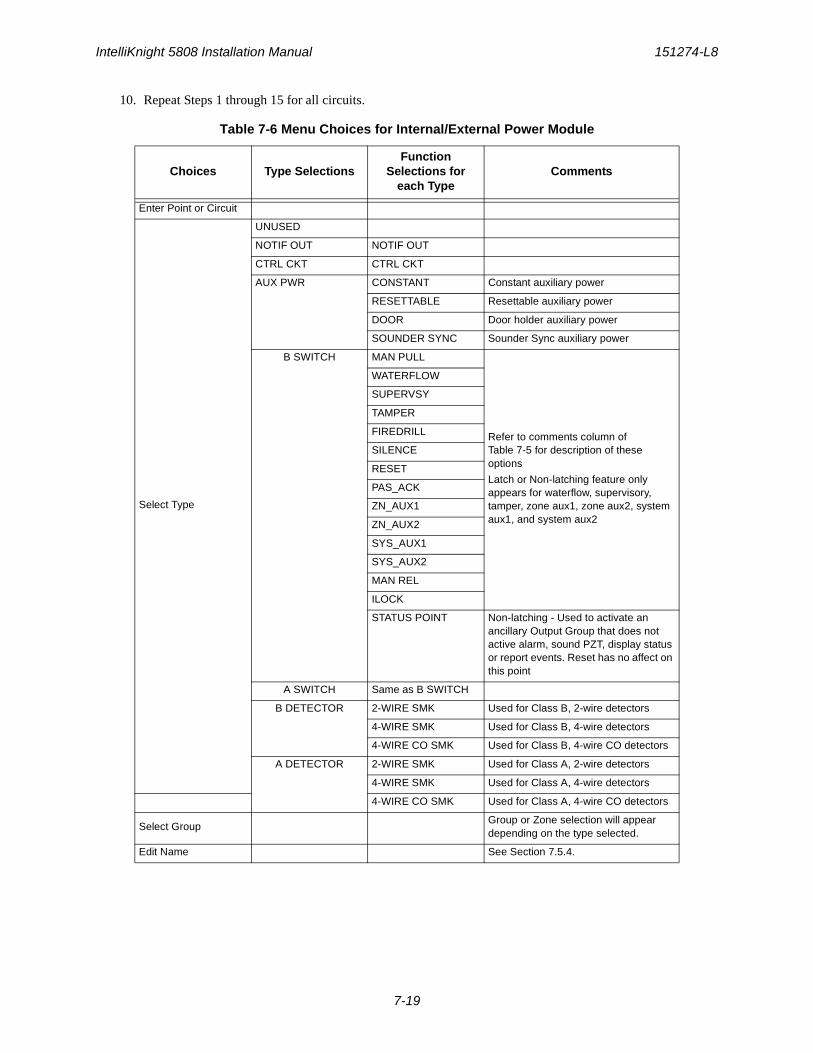
IntelliKnight 5808 Installation Manual 151274-L8
7-19
10. Repeat Steps 1 through 15 for all circuits.
Table 7-6 Menu Choices for Internal/External Power Module
Choices Type SelectionsFunction
Selections for each Type
Comments
Enter Point or Circuit
Select Type
UNUSED
NOTIF OUT NOTIF OUT
CTRL CKT CTRL CKT
AUX PWR CONSTANT Constant auxiliary power
RESETTABLE Resettable auxiliary power
DOOR Door holder auxiliary power
SOUNDER SYNC Sounder Sync auxiliary power
B SWITCH MAN PULL
Refer to comments column ofTable 7-5 for description of these options
Latch or Non-latching feature only appears for waterflow, supervisory, tamper, zone aux1, zone aux2, system aux1, and system aux2
WATERFLOW
SUPERVSY
TAMPER
FIREDRILL
SILENCE
RESET
PAS_ACK
ZN_AUX1
ZN_AUX2
SYS_AUX1
SYS_AUX2
MAN REL
ILOCK
STATUS POINT Non-latching - Used to activate an ancillary Output Group that does not active alarm, sound PZT, display status or report events. Reset has no affect on this point
A SWITCH Same as B SWITCH
B DETECTOR 2-WIRE SMK Used for Class B, 2-wire detectors
4-WIRE SMK Used for Class B, 4-wire detectors
4-WIRE CO SMK Used for Class B, 4-wire CO detectors
A DETECTOR 2-WIRE SMK Used for Class A, 2-wire detectors
4-WIRE SMK Used for Class A, 4-wire detectors
4-WIRE CO SMK Used for Class A, 4-wire CO detectors
Select GroupGroup or Zone selection will appear depending on the type selected.
Edit Name See Section 7.5.4.

Programming 151274-L8
7-20
7.5.3 Point Programming For 5880 and 5865 Modules
To program 5880 or 5865 module points:
1. Enter the installer code.
2. Select 7 for Program Menu.
3. Press 4 to enter point menu.
4. Press the or arrows to select the desired module. Refer to Section 6.5 for available choices. Press ENTER.
Figure 7-11 Programming Points Screen for 5880 and 5865 Modules
5. Enter the point number. Press ENTER.
6. Press the or arrows to select the type (Notification or unused). Press ENTER.
7. Press the or arrows to select the desired Group. Press ENTER.
8. Edit module name. See Section 7.5.4, or Press the right arrow to skip module name edit.
9. Repeat Steps 1 through 8 for all points.
7.5.4 Assigning a Name to a Point
You can assign a name to a point to make it easier to recognize on a display.
If you wish to edit the name of a point, follow these instructions:
1. Do steps 1 through 4 of Section 7.5.3.
2. Using the or arrow, select the module of the point you want to edit, press ENTER.
3. Enter the point number.
4. Press the right arrow until the module name is blinking. Press ENTER.
A screen similar to the one shown in Figure 7-12 displays.
Figure 7-12 Selecting Character for Zone Name
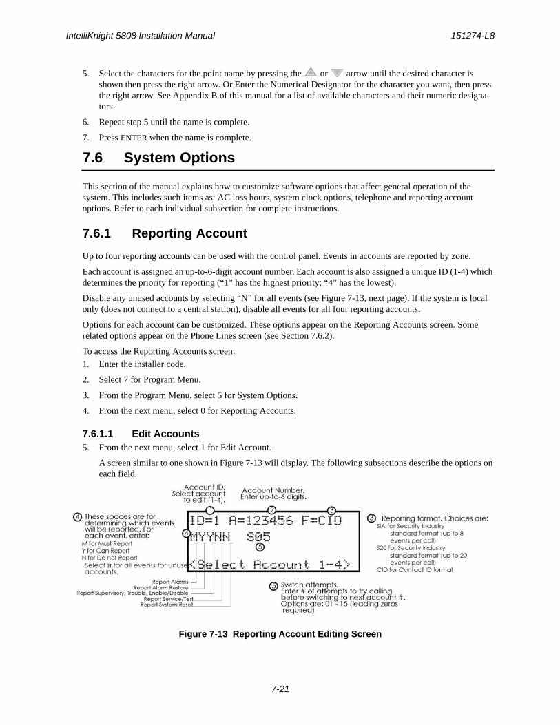
IntelliKnight 5808 Installation Manual 151274-L8
7-21
5. Select the characters for the point name by pressing the or arrow until the desired character is shown then press the right arrow. Or Enter the Numerical Designator for the character you want, then press the right arrow. See Appendix B of this manual for a list of available characters and their numeric designa-tors.
6. Repeat step 5 until the name is complete.
7. Press ENTER when the name is complete.
7.6 System Options
This section of the manual explains how to customize software options that affect general operation of the system. This includes such items as: AC loss hours, system clock options, telephone and reporting account options. Refer to each individual subsection for complete instructions.
7.6.1 Reporting Account
Up to four reporting accounts can be used with the control panel. Events in accounts are reported by zone.
Each account is assigned an up-to-6-digit account number. Each account is also assigned a unique ID (1-4) which determines the priority for reporting (“1” has the highest priority; “4” has the lowest).
Disable any unused accounts by selecting “N” for all events (see Figure 7-13, next page). If the system is local only (does not connect to a central station), disable all events for all four reporting accounts.
Options for each account can be customized. These options appear on the Reporting Accounts screen. Some related options appear on the Phone Lines screen (see Section 7.6.2).
To access the Reporting Accounts screen:
1. Enter the installer code.
2. Select 7 for Program Menu.
3. From the Program Menu, select 5 for System Options.
4. From the next menu, select 0 for Reporting Accounts.
7.6.1.1 Edit Accounts5. From the next menu, select 1 for Edit Account.
A screen similar to one shown in Figure 7-13 will display. The following subsections describe the options on each field.
Figure 7-13 Reporting Account Editing Screen
Programming 151274-L8
7-22
Select Account (ID)The control panel provides up to 4 reporting accounts. The priority of an account is based on its account ID. Account 1 is highest priority; Account 4 is lowest. Use Account 1 to report the highest priority events.
6. Press the or arrow to select account ID number, then press ENTER.
Edit Account NumberEnter an up-to-6-digit number for each account to identify the account to the central station. See Figure 7-13 for location of this option on the screen. The account number should be compatible with the reporting format used. For example, the Contact ID format transmits up to four digits only.
7. Enter the desired account number (up to 6-digits), then press ENTER.
Select Reporting FormatSelect a reporting format for each account. Options are:
8. Press the or arrow to select the reporting format, then press ENTER.
Events to ReportThe next five options select which types of events (or event families) will be reported to this account. (See Figure 7-13 for location of these options on the screen).
9. Press the or arrow to select Must, Yes, or No (see Table below), then press ENTER.
10. Repeat step 9 for all five event report options.
For each event family, select M, Y, or N.
Switch AttemptsSpecify the number of times the dialer should attempt to report to this account before switching to the next
SIA SIA format. 8 events per call.
CID Ademco’s Contact ID format
S20 Same as SIA but reports up to 20 events per phone call.
Event Family Events Included in this Family
Alarms All alarms (Water Flow, Manual Pull, Detectors, Auxiliary Switches, Etc.)
Alarm Restore All alarm restores.
Supervisory, Trouble, Enable/Disable Point
All trouble and supervisory conditions and trouble and supervisory restores. Enabling and disabling of input and output points.
Service/Test Fire drill, walk test, dialer test, automatic test, all programming sessions.
System Reset All system resets.
M(ust) Must Report. Selecting “M” makes this a primary reporting account for this family of events. The dialer MUST report events in this family to this account.
Selecting Must makes an account a primary reporting account. The dialer will try to report the event to the primary account until it exceeds the “Switch Attempts” value. When the dialer has exceeded the Switch Attempt retry limit, it will switch to a backup account (a “Can Report” or “Yes” account, see below). If the dialer cannot report the event to any of the backup accounts, it will return to the primary account and repeat the process until it succeeds or an Account Trouble condition is generated and a local trouble will sound.
Y(es) Can Report. Selecting Y makes this a backup account for this event family. The dialer will report to this account only if it was previously unable to report the event to a Must account.
N(o) No events in this family will ever be reported to this account.
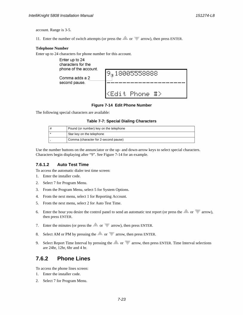
IntelliKnight 5808 Installation Manual 151274-L8
7-23
account. Range is 3-5.
11. Enter the number of switch attempts (or press the or arrow), then press ENTER.
Telephone NumberEnter up to 24 characters for phone number for this account.
Figure 7-14 Edit Phone Number
The following special characters are available:
Use the number buttons on the annunciator or the up- and down-arrow keys to select special characters. Characters begin displaying after “9”. See Figure 7-14 for an example.
7.6.1.2 Auto Test TimeTo access the automatic dialer test time screen:
1. Enter the installer code.
2. Select 7 for Program Menu.
3. From the Program Menu, select 5 for System Options.
4. From the next menu, select 1 for Reporting Account.
5. From the next menu, select 2 for Auto Test Time.
6. Enter the hour you desire the control panel to send an automatic test report (or press the or arrow), then press ENTER.
7. Enter the minutes (or press the or arrow), then press ENTER.
8. Select AM or PM by pressing the or arrow, then press ENTER.
9. Select Report Time Interval by pressing the or arrow, then press ENTER. Time Interval selections are 24hr, 12hr, 6hr and 4 hr.
7.6.2 Phone Lines
To access the phone lines screen:
1. Enter the installer code.
2. Select 7 for Program Menu.
Table 7-7: Special Dialing Characters
# Pound (or number) key on the telephone
* Star key on the telephone
, Comma (character for 2-second pause)
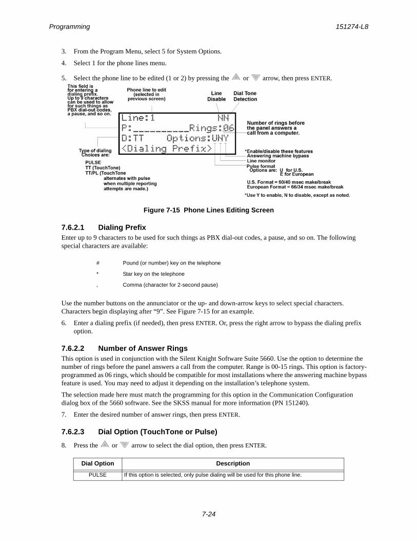
Programming 151274-L8
7-24
3. From the Program Menu, select 5 for System Options.
4. Select 1 for the phone lines menu.
5. Select the phone line to be edited (1 or 2) by pressing the or arrow, then press ENTER.
Figure 7-15 Phone Lines Editing Screen
7.6.2.1 Dialing PrefixEnter up to 9 characters to be used for such things as PBX dial-out codes, a pause, and so on. The following special characters are available:
Use the number buttons on the annunciator or the up- and down-arrow keys to select special characters. Characters begin displaying after “9”. See Figure 7-15 for an example.
6. Enter a dialing prefix (if needed), then press ENTER. Or, press the right arrow to bypass the dialing prefix option.
7.6.2.2 Number of Answer RingsThis option is used in conjunction with the Silent Knight Software Suite 5660. Use the option to determine the number of rings before the panel answers a call from the computer. Range is 00-15 rings. This option is factory-programmed as 06 rings, which should be compatible for most installations where the answering machine bypass feature is used. You may need to adjust it depending on the installation’s telephone system.
The selection made here must match the programming for this option in the Communication Configuration dialog box of the 5660 software. See the SKSS manual for more information (PN 151240).
7. Enter the desired number of answer rings, then press ENTER.
7.6.2.3 Dial Option (TouchTone or Pulse)
8. Press the or arrow to select the dial option, then press ENTER.
# Pound (or number) key on the telephone
* Star key on the telephone
, Comma (character for 2-second pause)
Dial Option Description
PULSE If this option is selected, only pulse dialing will be used for this phone line.
IntelliKnight 5808 Installation Manual 151274-L8
7-25
7.6.2.4 Rotary Format
9. Press the or arrow to select the pulse ratio for rotary dialing option, then press ENTER. Options are:
7.6.2.5 Line MonitorEnable the line monitor for each phone line that will be used. See Figure 7-15 for location of this field on the phone lines screen. When the phone line monitor has been enabled for a phone line, a trouble condition will occur if the line is not connected. If a phone line will not be used, it must be disabled.
10. Select Y (monitor line) or N (don’t monitor line) by pressing the or arrow, then press ENTER.
7.6.2.6 Answering Machine BypassThis option is used in conjunction with the Silent Knight Software Suite 5660. This feature ensures that an answering machine will not interfere with communication between the panel and the computer. If an answering machine is used at the panel site, enable this feature; if an answering machine is not used, disable the feature.
This option is factory-programmed as Yes (enabled).
The selection made here must match the programming for this option in the Communication Configuration dialog box of the 5660 software. See the manual for the software (p/n 151240) if you need more information.
11. Select Y (answering machine bypass enabled) or N (answering machine bypass disabled) by pressing the
or arrow, then press ENTER.
7.6.3 System Event Outputs
1. Enter the installer code.
2. Select 7 for Program Menu.
3. From the Program Menu, select 5 for System Options.
4. From the System Options Menu, select 2 for System Event Outputs.
7.6.3.1 Trouble EventsYou can map certain system trouble events to an output group. To access the screen for selecting output groups and cadence patterns for system trouble events.
5. Press 1 for Trouble Events. A screen similar to the one in Figure 7-16 will display. Select a group and a cadence pattern for each event as needed for your application. The U: field is for a user-specified trouble condition. You can program an output group and cadence pattern for any of the following events:
TT TouchTone dialing. If this option is selected, only TouchTone dialing will be used for this phone line.
TT/PL TouchTone alternating with pulse. If this option is selected, the dialer will first attempt to use TouchTone. It will switch to pulse if TouchTone is not successful on the first attempt. It will continue to alternate between TT and pulse for additional attempts.
U U.S. standard format. Uses the 60 msec / 40 msec make/break ratio.
E European format. Uses the 66 msec / 34 msec make/break ratio.
Battery Low battery condition.
Phone Ln Phone Line 1 or 2 trouble.
Account Account trouble; cannot report to account.
Printer Printer trouble. (Currently not supported; do not select.)
Dial Option Description
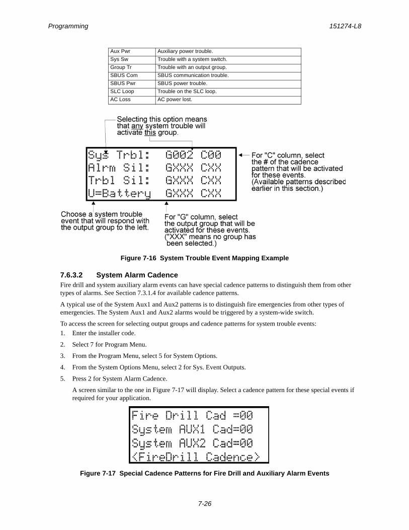
Programming 151274-L8
7-26
Figure 7-16 System Trouble Event Mapping Example
7.6.3.2 System Alarm CadenceFire drill and system auxiliary alarm events can have special cadence patterns to distinguish them from other types of alarms. See Section 7.3.1.4 for available cadence patterns.
A typical use of the System Aux1 and Aux2 patterns is to distinguish fire emergencies from other types of emergencies. The System Aux1 and Aux2 alarms would be triggered by a system-wide switch.
To access the screen for selecting output groups and cadence patterns for system trouble events:
1. Enter the installer code.
2. Select 7 for Program Menu.
3. From the Program Menu, select 5 for System Options.
4. From the System Options Menu, select 2 for Sys. Event Outputs.
5. Press 2 for System Alarm Cadence.
A screen similar to the one in Figure 7-17 will display. Select a cadence pattern for these special events if required for your application.
Figure 7-17 Special Cadence Patterns for Fire Drill and Auxiliary Alarm Events
Aux Pwr Auxiliary power trouble.
Sys Sw Trouble with a system switch.
Group Tr Trouble with an output group.
SBUS Com SBUS communication trouble.
SBUS Pwr SBUS power trouble.
SLC Loop Trouble on the SLC loop.
AC Loss AC power lost.
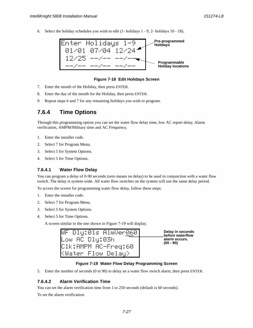
IntelliKnight 5808 Installation Manual 151274-L8
7-27
6. Select the holiday schedules you wish to edit (1- holidays 1 - 9, 2- holidays 10 - 18).
Figure 7-18 Edit Holidays Screen
7. Enter the month of the Holiday, then press ENTER.
8. Enter the day of the month for the Holiday, then press ENTER.
9. Repeat steps 6 and 7 for any remaining holidays you wish to program.
7.6.4 Time Options
Through this programming option you can set the water flow delay time, low AC report delay, Alarm verification, AMPM/Military time and AC Frequency.
1. Enter the installer code.
2. Select 7 for Program Menu.
3. Select 5 for System Options.
4. Select 5 for Time Options.
7.6.4.1 Water Flow DelayYou can program a delay of 0-90 seconds (zero means no delay) to be used in conjunction with a water flow switch. The delay is system-wide. All water flow switches on the system will use the same delay period.
To access the screen for programming water flow delay, follow these steps:
1. Enter the installer code.
2. Select 7 for Program Menu.
3. Select 5 for System Options.
4. Select 5 for Time Options.
A screen similar to the one shown in Figure 7-19 will display.
Figure 7-19 Water Flow Delay Programming Screen
5. Enter the number of seconds (0 to 90) to delay an a water flow switch alarm, then press ENTER.
7.6.4.2 Alarm Verification TimeYou can set the alarm verification time from 1 to 250 seconds (default is 60 seconds).
To set the alarm verification:
Pre-programmedHolidays
ProgrammableHoliday locations
Delay in secondsbefore waterflowalarm occurs.(00 - 90)

Programming 151274-L8
7-28
6. Enter the desired number of seconds for the alarm verification time.
7. Press or ENTER to make your selection and move to the next programming option.
7.6.4.3 Low AC Report DelayNote: You must select 1-3 hours in UL central station installations and UL remote signaling installations.
You can adjust the number of hours before a Low AC report will be sent to the central station.
To program low AC report delay, follow these steps:
Note: Steps continued from step 7 of Section 7.6.4.1.
Figure 7-20 Low AC Report Delay Programming Screen
8. Enter the number of hours before a low AC report will be sent to the central station, then press ENTER. Refer to Figure 7-20.
7.6.4.4 Clock Display Format (AM/PM or Military)To change the system clock display format, continue programming from step 8 above:
9. Select AMPM (for AM/Pm display format) or MIL (for military or 24 hr display format) by pressing the
or arrow, then press ENTER.
7.6.4.5 Change AC Line FrequencyThe panel’s AC line frequency is selectable for 50, 60 Hz, or Neither. AC Frequency feature dictates how the control panel will calculate time based on the AC line frequency used in the installation site. The “Neither” option can be used in areas where the AC line frequency is not dependable and you want the panel to calculate time from the internal crystal. The internal crystal is not as accurate as the AC power source and either 60 Hz or 50 Hz should normally be selected. The panel defaults to the 60 Hz. selection
To change the AC line frequency, continue programming from step 9 above:
10. Select 50, 60 or Neither, by pressing the or arrow, then press ENTER.
7.6.5 Miscellaneous Options
Through this programming option you can turn on or off strobe synchronization during silence, display status at idle (auto display event), report by zone or point, plexiglass door, and single key ack.
To edit Miscellaneous Options:
1. Enter the installer code.
2. Select 7 for Program Menu.
3. Select 5 for System Options.
4. Select 6 for Misc. Options.
7.6.5.1 Synchronize Strobes Active During SilenceWhen “SYNC Strbs w/ Sil:” is Selected as Y (Yes) then strobes will continue to flash when the system is silenced and will stop flashing when the system is reset.
Low AC ReportDelay in Hours(00 - 30)

IntelliKnight 5808 Installation Manual 151274-L8
7-29
Note: The “SYNC Strbs w/ Sil:” only functions with outputs that use a synchronized output pattern.
5. Press the or arrow to toggle this selection between Y (Yes) or N (No).
6. Press the right arrow or ENTER to make your selection and move to the next programming option.
Note: See Section 7.3.1.4 for more information about Synchronization protocol choices.
7.6.5.2 Auto Display Oldest EventWhen this feature is programmed Y (Yes) then the oldest un-acknowledge event will automatically display on the control panel and remote annunciators after there has been no activity on any system touchpad for two minutes.
7. Press the or arrow to toggle this selection between Y (Yes) or N (No).
8. Press the right arrow or ENTER to make your selection and move to the next programming option.
7.6.5.3 Report by Zone or by PointWhen the “Report by” option is set to Zone, then the control panel will report events by zone. If Point is selected then the control panel will report events by point.
9. Press the or arrow to toggle this selection between Zone or Point.
10. Then press the right arrow or ENTER. See Section 9 for reporting codes.
7.6.5.4 Plex Door OptionIf installing the plex door hardware (PN Plex-2), you must turn the Plex Door option On as described in this section.
To turn the Plex Door option on/off:
11. Press the or arrow to toggle this selection between Y (Yes) or N (No).
12. Press the right arrow of ENTER to make your selection and move to the next programming option.
7.6.5.5 Single Key AcknowledgeWhen this feature is programmed Y (Yes) allows the user to press ACK and display the oldest un-acknowledged event in the system. Pressing ACK again will acknowledge the event, then display the next oldest un-
acknowledge event without pressing the or arrow.
7.6.6 Daylight Savings
From Daylight Savings, you set the set the start and end week and month of Daylight Saving Time.
To edit Daylight Savings:1. Enter the installer code.
2. Select 7 for Program Menu.
3. Select 5 for System Options.
4. Select 7 for Daylight Savings.
7.6.6.1 Automatic Daylight Saving Time AdjustmentThe control panel has an automatic DST (Daylight Saving Time) adjustment feature. Before January 2007, if this feature is enabled (set to Yes), the system clock will switch to DST on the first Sunday in April at 2:00 a.m. and revert to standard time on the last Sunday in October at 2:00 a.m. After January 2007, if this feature is enabled, the system clock will start and end DST according to the settings made in Daylight Savings. If this feature is not

Programming 151274-L8
7-30
enabled (set to No) the Daylight Saving Time change is not made to the system clock.
To enable or disable DST adjustment continue programming from step 4 above:
1. Select Y (enabled) or N (disabled) by pressing the or arrow, then press ENTER.
7.6.6.2 Daylight Saving Time Start and EndThis option lets you to adjust the week and month Daylight Saving Time (DST) starts and ends. For this feature to work, you must enable (set to Yes) the DST option under Daylight Savings. You can view and change the settings in this option anytime, however, settings will not take effect until 2007. The default values for the DST Start and End options reflect the August 8, 2005 DST law that goes into effect in 2007:
DST Start: The second Sunday in MarchDST End: The first Sunday in November
To set the start and end for Daylight Saving Time:
1. Press the or arrow to select the week (1st, 2nd, etc.) Daylight Saving Time starts, then press ENTER to make your selection and move to the month setting.
2. Press the or arrow to select the month (January – December) Daylight Saving Time starts, then press ENTER to make your selection and move to the DST End option.
3. Press the or arrow to select the week (1st, 2nd, etc.) Daylight Saving Time ends, then press ENTER to make your selection and move to the month setting.
4. Press the or arrow to select the month (January – December) Daylight Saving Time ends, then press ENTER two times to make your selection and exit.
7.6.7 Edit Banner Message
The banner is the message that displays on the panel LCD when the system is normal, that is, when no alarms or troubles exist and no one is currently using system menus. You can create a customized message, which can be up to 40 characters, two lines of 20 characters each.
If you do not create a customized message, the system will use the internal banner. You cannot change the internal banner.
To customize the banner display message:
1. Enter the installer code.
2. Select 7 for Program Menu.
3. Select 5 for System Options.
4. Select 8 for Edit Banner.
A screen similar to the one shown in Figure 7-21 will display.
Figure 7-21 Internal Banner Message
5. Press the or arrow to select “Custom”, then press ENTER.
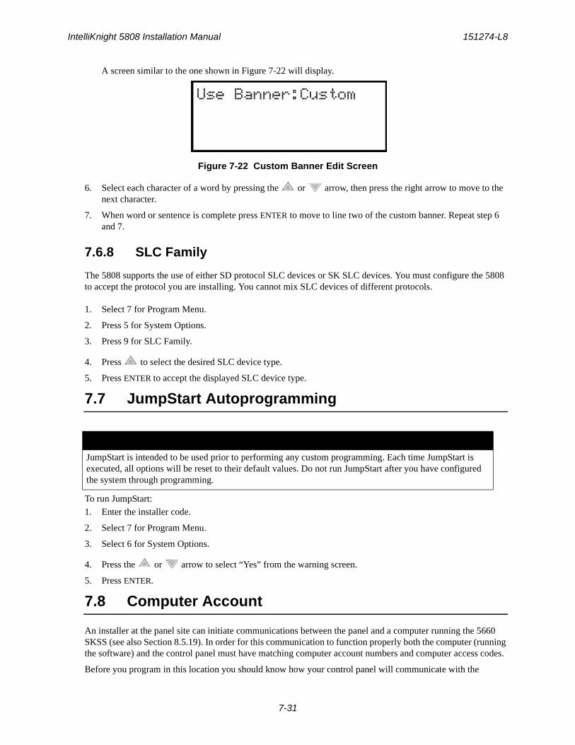
IntelliKnight 5808 Installation Manual 151274-L8
7-31
A screen similar to the one shown in Figure 7-22 will display.
Figure 7-22 Custom Banner Edit Screen
6. Select each character of a word by pressing the or arrow, then press the right arrow to move to the next character.
7. When word or sentence is complete press ENTER to move to line two of the custom banner. Repeat step 6 and 7.
7.6.8 SLC Family
The 5808 supports the use of either SD protocol SLC devices or SK SLC devices. You must configure the 5808 to accept the protocol you are installing. You cannot mix SLC devices of different protocols.
1. Select 7 for Program Menu.
2. Press 5 for System Options.
3. Press 9 for SLC Family.
4. Press to select the desired SLC device type.
5. Press ENTER to accept the displayed SLC device type.
7.7 JumpStart Autoprogramming
To run JumpStart:
1. Enter the installer code.
2. Select 7 for Program Menu.
3. Select 6 for System Options.
4. Press the or arrow to select “Yes” from the warning screen.
5. Press ENTER.
7.8 Computer Account
An installer at the panel site can initiate communications between the panel and a computer running the 5660 SKSS (see also Section 8.5.19). In order for this communication to function properly both the computer (running the software) and the control panel must have matching computer account numbers and computer access codes.
Before you program in this location you should know how your control panel will communicate with the
IMPORTANT!
JumpStart is intended to be used prior to performing any custom programming. Each time JumpStart is executed, all options will be reset to their default values. Do not run JumpStart after you have configured the system through programming.
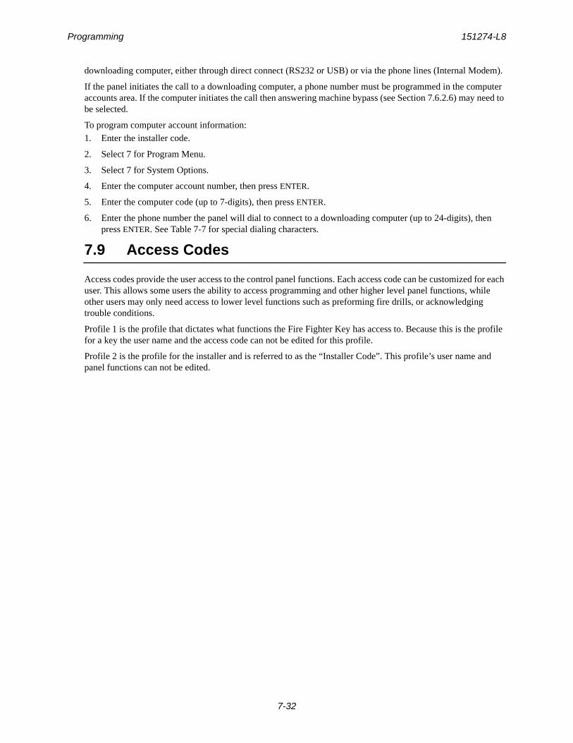
Programming 151274-L8
7-32
downloading computer, either through direct connect (RS232 or USB) or via the phone lines (Internal Modem).
If the panel initiates the call to a downloading computer, a phone number must be programmed in the computer accounts area. If the computer initiates the call then answering machine bypass (see Section 7.6.2.6) may need to be selected.
To program computer account information:
1. Enter the installer code.
2. Select 7 for Program Menu.
3. Select 7 for System Options.
4. Enter the computer account number, then press ENTER.
5. Enter the computer code (up to 7-digits), then press ENTER.
6. Enter the phone number the panel will dial to connect to a downloading computer (up to 24-digits), then press ENTER. See Table 7-7 for special dialing characters.
7.9 Access Codes
Access codes provide the user access to the control panel functions. Each access code can be customized for each user. This allows some users the ability to access programming and other higher level panel functions, while other users may only need access to lower level functions such as preforming fire drills, or acknowledging trouble conditions.
Profile 1 is the profile that dictates what functions the Fire Fighter Key has access to. Because this is the profile for a key the user name and the access code can not be edited for this profile.
Profile 2 is the profile for the installer and is referred to as the “Installer Code”. This profile’s user name and panel functions can not be edited.

IntelliKnight 5808 Installation Manual 151274-L8
7-33
Table 7-8 lists the panel functions that can be selected for each user profile.
To change an access code:
1. Enter the installer code.
2. Select 7 for Program Menu.
3. Select 8 for System Options.
Display reads:Select Profile 01
Fire Fighter’s Key
4. Select the access code you wish to edit by pressing the or arrow. Then press ENTER.
7.9.1 Profile Edit Menu
From the Profile Edit Menu you can change the users name, access code, and the panel functions that the user will have access to with their code.
Table 7-8: User Profile Selectable Panel Functions
Type of Function Selectable Functions
Panel Operations System Reset
System Silence
Event Acknowledge
Panel Menus System Test
Fire Drill
Indicator Test
Walk Test no Report
Walk Test with Report
Dialer Test
Clear History Buffer
Point Functions
Disable/Enable Point
Point Status
Set SLC Device Address
SLC Device Locator
SLC Mult-Device Locator
I/O Point Control
Event History
Set Time & Date
Printer Options
Event Logging
Print Event History
Print Detector Status
Print System Configuration
Reset Dialer
Program Menu
System Information
Upload/Download

Programming 151274-L8
7-34
Note: Profile 1 (Fire Fighter’s Key) the user name and access code can not be edited. Profile 2 (Installer) the user name and panel functions can not be edited.
7.9.1.1 Edit Name
5. Select each character of a word by pressing the or arrow, then press the right arrow to move to the next character.
6. Repeat step 7 until user name is complete. Then press ENTER to finish.
7.9.1.2 Edit Access Code7. Enter new access code (minimum of 4 digits, maximum of 7 digit). Press ENTER.
8. Enter code again. Press ENTER.
7.9.1.3 Panel Functions
9. Press the or arrow to move through the list of available functions.
10. Then press the right arrow to move to Y (yes) or N (no) selection column.
11. Press the or arrow to select Y or N. Press ENTER.
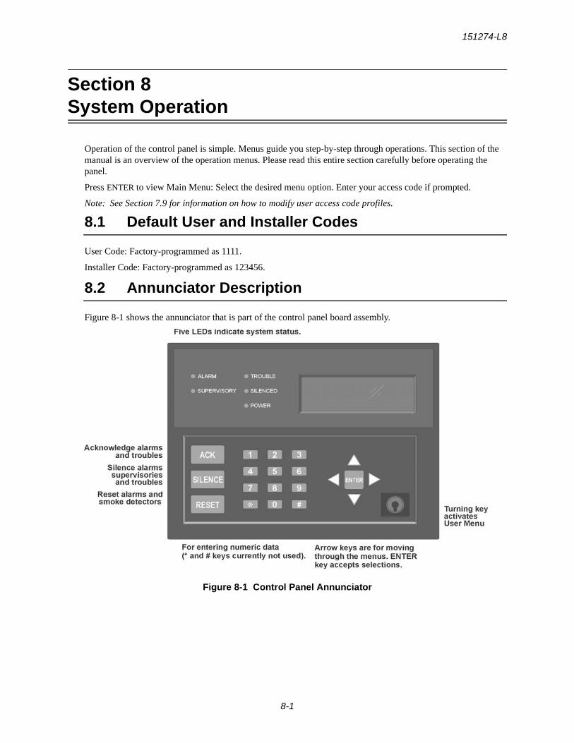
151274-L8
8-1
Section 8System Operation
Operation of the control panel is simple. Menus guide you step-by-step through operations. This section of the manual is an overview of the operation menus. Please read this entire section carefully before operating the panel.
Press ENTER to view Main Menu: Select the desired menu option. Enter your access code if prompted.
Note: See Section 7.9 for information on how to modify user access code profiles.
8.1 Default User and Installer Codes
User Code: Factory-programmed as 1111.
Installer Code: Factory-programmed as 123456.
8.2 Annunciator Description
Figure 8-1 shows the annunciator that is part of the control panel board assembly.
Figure 8-1 Control Panel Annunciator
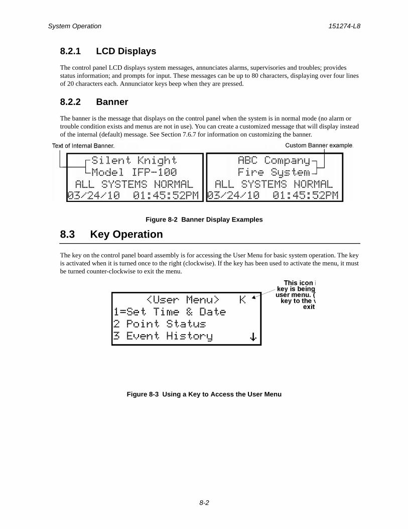
System Operation 151274-L8
8-2
8.2.1 LCD Displays
The control panel LCD displays system messages, annunciates alarms, supervisories and troubles; provides status information; and prompts for input. These messages can be up to 80 characters, displaying over four lines of 20 characters each. Annunciator keys beep when they are pressed.
8.2.2 Banner
The banner is the message that displays on the control panel when the system is in normal mode (no alarm or trouble condition exists and menus are not in use). You can create a customized message that will display instead of the internal (default) message. See Section 7.6.7 for information on customizing the banner.
Figure 8-2 Banner Display Examples
8.3 Key Operation
The key on the control panel board assembly is for accessing the User Menu for basic system operation. The key is activated when it is turned once to the right (clockwise). If the key has been used to activate the menu, it must be turned counter-clockwise to exit the menu.
Figure 8-3 Using a Key to Access the User Menu
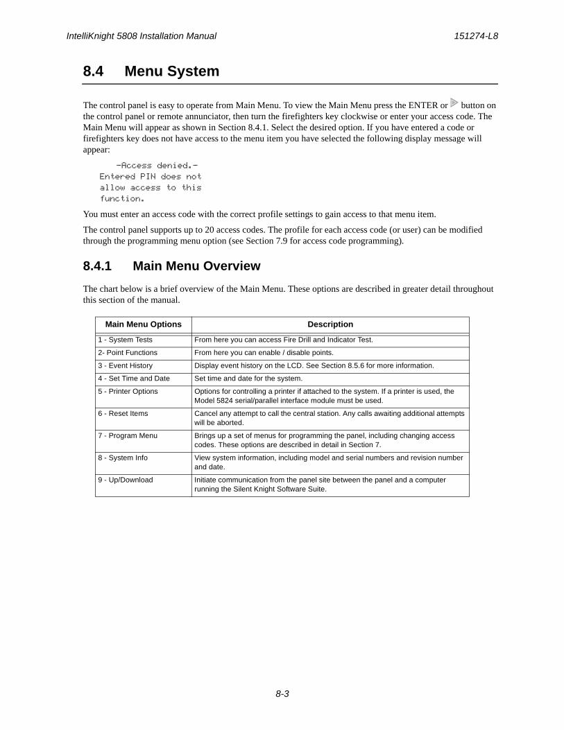
IntelliKnight 5808 Installation Manual 151274-L8
8-3
8.4 Menu System
The control panel is easy to operate from Main Menu. To view the Main Menu press the ENTER or button on the control panel or remote annunciator, then turn the firefighters key clockwise or enter your access code. The Main Menu will appear as shown in Section 8.4.1. Select the desired option. If you have entered a code or firefighters key does not have access to the menu item you have selected the following display message will appear:
-Access denied.-Entered PIN does notallow access to thisfunction.
You must enter an access code with the correct profile settings to gain access to that menu item.
The control panel supports up to 20 access codes. The profile for each access code (or user) can be modified through the programming menu option (see Section 7.9 for access code programming).
8.4.1 Main Menu Overview
The chart below is a brief overview of the Main Menu. These options are described in greater detail throughout this section of the manual.
Main Menu Options Description
1 - System Tests From here you can access Fire Drill and Indicator Test.
2- Point Functions From here you can enable / disable points.
3 - Event History Display event history on the LCD. See Section 8.5.6 for more information.
4 - Set Time and Date Set time and date for the system.
5 - Printer Options Options for controlling a printer if attached to the system. If a printer is used, the Model 5824 serial/parallel interface module must be used.
6 - Reset Items Cancel any attempt to call the central station. Any calls awaiting additional attempts will be aborted.
7 - Program Menu Brings up a set of menus for programming the panel, including changing access codes. These options are described in detail in Section 7.
8 - System Info View system information, including model and serial numbers and revision number and date.
9 - Up/Download Initiate communication from the panel site between the panel and a computer running the Silent Knight Software Suite.
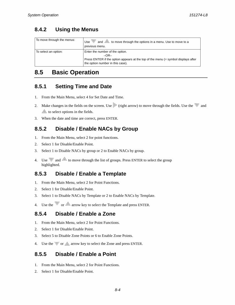
System Operation 151274-L8
8-4
8.4.2 Using the Menus
8.5 Basic Operation
8.5.1 Setting Time and Date
1. From the Main Menu, select 4 for Set Date and Time.
2. Make changes in the fields on the screen. Use (right arrow) to move through the fields. Use the and
to select options in the fields.
3. When the date and time are correct, press ENTER.
8.5.2 Disable / Enable NACs by Group
1. From the Main Menu, select 2 for point functions.
2. Select 1 for Disable/Enable Point.
3. Select 1 to Disable NACs by group or 2 to Enable NACs by group.
4. Use and to move through the list of groups. Press ENTER to select the group highlighted.
8.5.3 Disable / Enable a Template
1. From the Main Menu, select 2 for Point Functions.
2. Select 1 for Disable/Enable Point.
3. Select 1 to Disable NACs by Template or 2 to Enable NACs by Template.
4. Use the or arrow key to select the Template and press ENTER.
8.5.4 Disable / Enable a Zone
1. From the Main Menu, select 2 for Point Functions.
2. Select 1 for Disable/Enable Point.
3. Select 5 to Disable Zone Points or 6 to Enable Zone Points.
4. Use the or arrow key to select the Zone and press ENTER.
8.5.5 Disable / Enable a Point
1. From the Main Menu, select 2 for Point Functions.
2. Select 1 for Disable/Enable Point.
To move through the menus:Use and to move through the options in a menu. Use to move to a previous menu.
To select an option: Enter the number of the option.–OR–
Press ENTER if the option appears at the top of the menu (= symbol displays after the option number in this case).
IntelliKnight 5808 Installation Manual 151274-L8
8-5
3. Select 7 for Disable/Enable Pt.
4. Use and to move through the list. Press ENTER to select the module where the point you want to disable/enable is located. A description of the point should display. The fourth line of the screen should show “NORMAL” (meaning that the point is currently enabled) or “DISABLED” (the point is currently dis-
abled). Press to toggle between NORMAL and DISABLE.
8.5.6 View Event History
Use the View Event History feature to display events on LCD. From the Main Menu, press 3 to select Event History. Events will begin displaying with most recent events first.
The panel can store up to 1000 events. When it reaches its 1000-event capacity, it begins deleting, starting with the oldest events.
If a printer is attached to the system (via a Module 5824 serial/parallel interface module), you can print event history (see Section 8.5.20).
The 5660 SKSS can be used to retain more than 1000 events and to create event history reports.
8.5.7 Clear Event HistoryFrom the main menu select 1 for System Tests. From the test menu select 6 Clear History Buffer.
8.5.8 Conduct a Fire Drill1. From the Main Menu, press 1 for System Tests.
2. Press 1 for Fire Drill. You will be prompted to press ENTER.
3. The drill will begin immediately after you press ENTER.
4. Press any key to end the drill. (If you do not press any key to end the fire drill manually, it will time out auto-matically after ten minutes).
If a fire drill switch has been installed, activating the switch will begin the drill; deactivating the switch will end the drill.
8.5.9 Conduct an Indicator TestThe indicator test checks the annunciator LEDs and the PZT sounder.
1. From the Main Menu, press 1 for System Tests.
2. Press 2 for Indicator Test. The system turns on each LED and beeps the PZT. A problem is indicated if any of the following occurs:
• An LED does not turn on
• You do not hear a PZT beep
The test will time out after 15 minutes or you can press any key on the annunciator to end the test manually. When the test ends, you will be returned to the System Test Menu.
System Operation 151274-L8
8-6
8.5.10 Conduct a Walk Test1. From the Main Menu, press 1 for System Tests.
2. Select 3 for Walk Test-No Rpt. Enter the time period you wish the NAC circuit to be active for each alarm (06 to 180 seconds). The LCD will display “WALK TEST STOPPED” on Line 1 and “ENTER = start test” on Line 3. By selecting this option, central station reporting is disabled while the test is in progress.
Or
Select 4 for Walk Test-with Rpt. Enter the time period you wish the NAC circuit to be active for each alarm (06 to 180 seconds). The LCD will display “WALK TEST STOPPED” on Line 1 and “ENTER = start test” on Line 3. By selecting this option, central station reporting will occur as normal during the walk test.
The panel generates a TEST report to the central station when the walk test begins. During a walk test, the panel’s normal fire alarm function is completely disabled, placing the panel in a local trouble condition. All zones respond as 1-Count zones (respond when a single detector is in alarm) during a walk test. Each alarm initiated during the walk test will be reported and stored in the event history buffer.
3. Press ENTER to end the walk test. The system will reset. The panel will send a “TEST RESTORE” report to the central station.
If you do not end the walk test manually within four hours, it will end automatically. If an alarm or pre-alarm condition is occurring in the system, you will not be able to enter the walk test.
Note: the panel does not do a full 30 second reset on resettable power outputs. As soon as the device is back to normal, the panel is ready to go to the next device.
8.5.11 Conduct a Dialer Test1. From the Main Menu, press 1 for System Tests.
2. Select 5 for Dialer Test. The screen will display “Manual dialer test started”. When the test is completed, you will be returned to the <Test Menu>.
8.5.12 Silence Alarms or Troubles
Press SILENCE and enter your code or rotate the key at the prompt. If an external silence switch has been installed, activating the switch will silence alarms or troubles. If you are already using system menus when you press SILENCE, you will not need to enter your code or rotate the key.
Note: Alarm and trouble signals that have been silenced but the detector remains un-restored will un-silence every 24 hours until it is restored.
8.5.13 Reset Alarms
Press RESET and enter your code or rotate the key at the prompt. If an external reset switch has been installed, activating the switch will reset alarms. If you are already using system menus when you press RESET, you will not need to enter your code or rotate the key.
IMPORTANT!
If any alarm verification zones are being used, the user will be asked if they wish to disable alarm verification during walk test. This occurs for either walk test option.
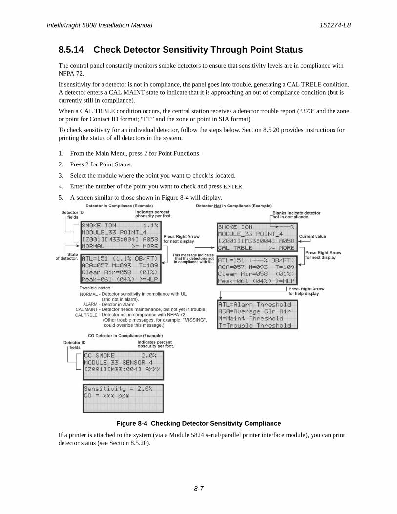
IntelliKnight 5808 Installation Manual 151274-L8
8-7
8.5.14 Check Detector Sensitivity Through Point Status
The control panel constantly monitors smoke detectors to ensure that sensitivity levels are in compliance with NFPA 72.
If sensitivity for a detector is not in compliance, the panel goes into trouble, generating a CAL TRBLE condition. A detector enters a CAL MAINT state to indicate that it is approaching an out of compliance condition (but is currently still in compliance).
When a CAL TRBLE condition occurs, the central station receives a detector trouble report (“373” and the zone or point for Contact ID format; “FT” and the zone or point in SIA format).
To check sensitivity for an individual detector, follow the steps below. Section 8.5.20 provides instructions for printing the status of all detectors in the system.
1. From the Main Menu, press 2 for Point Functions.
2. Press 2 for Point Status.
3. Select the module where the point you want to check is located.
4. Enter the number of the point you want to check and press ENTER.
5. A screen similar to those shown in Figure 8-4 will display.
Figure 8-4 Checking Detector Sensitivity Compliance
If a printer is attached to the system (via a Module 5824 serial/parallel printer interface module), you can print detector status (see Section 8.5.20).
System Operation 151274-L8
8-8
8.5.15 View Status of a Point
1. From the Main Menu, select 2 for Point Status.
2. From the list that displays, press ENTER to select the module where this point is located. Next, enter the point to display. The screen that displays will show you if the point has a trouble and will provide sensitivity compliance information. (See Section 8.5.14 for complete information about detector sensitivity compli-ance.)
8.5.16 View Alarms, Supervisories or Troubles
When the system is in alarm, supervisory or trouble, you can press to view the location of an alarm, supervisory or trouble.
8.5.17 View System Information
Press 8 from the Main Menu to view the panel model and serial number and system version number and date. Press Left arrow to return to the main menu.
8.5.18 Reset Items
From the Main Menu, select 6 for Reset Items.
8.5.18.1 Reset DialerThis options allows the user to Reset the Dialer. The LCD will display:
“Dialer Reset in progress… Please Wait“
You will be returned to the Main Menu when the reset is complete.
8.5.18.2 Reset DSP USBThis options allows the user to reset both the DSP Controller and USB interface logic. The LCD will display:
“Dialer Reset in progress… Please Wait“
You will be returned to the Main Menu when the reset is complete.
8.5.19 Communicating with a Remote Computer
An installer at the panel site can initiate communications between the panel and a computer running the Silent Knight Software Suite 5660. You can use this feature to upload a panel configuration. For example, if you have made programming changes to an installation on site using an annunciator, you can send your changes to the computer, so that the central station will have the latest data about the installation. See the software manual for more information (PN 151240).
To initiate communication, follow the steps below.
1. From the Main Menu, select 9 for Up/Download.
2. From the next screen that displays, select the communication device. Options are:
1 = Internal Modem If you select this option, you will use the panel’s built-in modem to call the computer.
2 = RS232 connection If you select this option, the panel and a computer are both on-site connected via a 9-pin straight-through serial cable.

IntelliKnight 5808 Installation Manual 151274-L8
8-9
3. If you are using the panel’s internal modem to communicate, you will be prompted to enter a phone number. If you are communicating via the RS232 connection, a phone number is not needed and this step will be skipped.
If the phone number you will be calling is already displayed, press ENTER. Continue with Step 4. If the phone number you will be calling is not already displayed, enter the number and press ENTER. A phone number can be up to 24 digits long and can contain the following special characters.
Use the number buttons on the annunciator or the up- and down-arrow keys to select special characters. Characters begin displaying after “9”.
4. You will be prompted to enter an account number. If the account number you want to use is already dis-played, just press ENTER to begin communication.
If the account number displayed is not the correct one, enter the account number and press ENTER to begin communication or view the next screen.
5. If you are using the panel's internal modem to communicate, you will be prompted to select a modem speed. Press ENTER on a speed to begin communication.
6. The panel will attempt to communicate with the computer. If communication was established, the upload task you created will be placed on the Downloading Software job queue, awaiting processing. When pro-cessing is completed, an “Unsolicited Upload” task will appear in the queue.
8.5.20 Working with a Printer
If you are using the Model 5824 serial/parallel printer interface module, several printing options are available. See Section 4.6 for information about installing the 5824.
1. From the Main Menu, select 5 Printer Options.
2. From the next screen, select the 5824 module where the printer is connected.
3. If the printer is not currently busy printing another report, a screen with the following options will be avail-able. If the printer is busy, a message will display. You can press 1 to cancel the current print job. These options will then display.
# Pound (or number) key on the telephone
* Star key on the telephone
, Comma (character for 2-second pause)
1= Event Logging Enables event logging, which causes the printer to continuously print events as they occur. The date/time will print in 24-hour military format. Once event logging is enabled, it will remain enabled until canceled by the installer. If you need to disable event logging, return to this option and press 1 to disable.
Sample Event Log
2 = Print Event History Prints the up-to-1000 events currently stored in the panel’s event history buffer. Events print starting with the newest. The date and time printed will be when the event actually occurred and will print in 24-hour military format.
EVENT LOG:
EVENT LOG:
STARTED: 02/17/97 02:23
STOPPED: 02/17/97 15:02
02/17/97 11:23 Event: System Silenced02/17/97 11:24 Event: System Reset02/17/97 14:30 Event: Local Programming Begin02/17/97 15:01 Event: Local Programming Ended Successfully
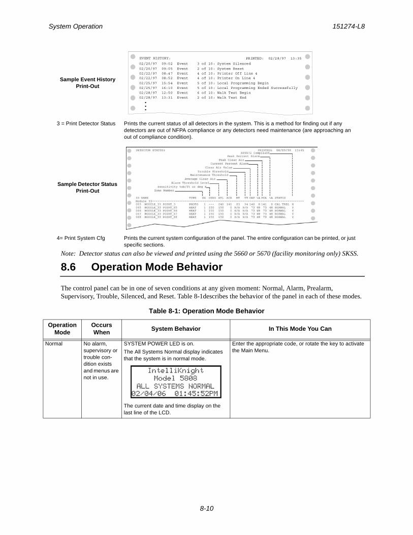
System Operation 151274-L8
8-10
Note: Detector status can also be viewed and printed using the 5660 or 5670 (facility monitoring only) SKSS.
8.6 Operation Mode Behavior
The control panel can be in one of seven conditions at any given moment: Normal, Alarm, Prealarm, Supervisory, Trouble, Silenced, and Reset. Table 8-1describes the behavior of the panel in each of these modes.
Sample Event History Print-Out
3 = Print Detector Status Prints the current status of all detectors in the system. This is a method for finding out if any detectors are out of NFPA compliance or any detectors need maintenance (are approaching an out of compliance condition).
Sample Detector Status Print-Out
4= Print System Cfg Prints the current system configuration of the panel. The entire configuration can be printed, or just specific sections.
Table 8-1: Operation Mode Behavior
Operation Mode
Occurs When
System Behavior In This Mode You Can
Normal No alarm, supervisory or trouble con-dition exists and menus are not in use.
SYSTEM POWER LED is on.
The All Systems Normal display indicates that the system is in normal mode.
The current date and time display on the last line of the LCD.
Enter the appropriate code, or rotate the key to activate the Main Menu.
EVENT HISTORY: PRINTED: 02/28/97 13:35
02/20/97 09:05 Event 2 of 10: System Reset
02/28/97 13:31 Event 2 of 10: Walk Test End
02/20/97 09:02 Event 3 of 10: System Silenced
02/22/97 08:47 Event 4 of 10: Printer Off Line 402/22/97 08:52 Event 4 of 10: Printer On Line 4
02/25/97 15:54 Event 5 of 10: Local Programming Begin02/25/97 16:10 Event 5 of 10: Local Programming Ended Successfully02/28/97 12:50 Event 6 of 10: Walk Test Begin
...
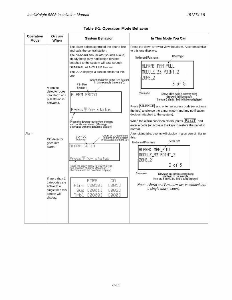
IntelliKnight 5808 Installation Manual 151274-L8
8-11
Alarm
A smoke detector goes into alarm or a pull station is activated.
CO detector goes into alarm.
If more than 3 categories are active at a single time this screen will display.
The dialer seizes control of the phone line and calls the central station.
The on-board annunciator sounds a loud, steady beep (any notification devices attached to the system will also sound).
GENERAL ALARM LED flashes.
The LCD displays a screen similar to this one.
Press the down arrow to view the alarm. A screen similar to this one displays.
Press and enter an access code (or activate the key) to silence the annunciator (and any notification devices attached to the system).
When the alarm condition clears, press and enter a code (or activate the key) to restore the panel to normal.
After sitting idle, events will display in a screen similar to this:
Note: Alarm and Prealarm are combined into a single alarm count.
Table 8-1: Operation Mode Behavior
Operation Mode
Occurs When
System Behavior In This Mode You Can
SILENCE
RESET
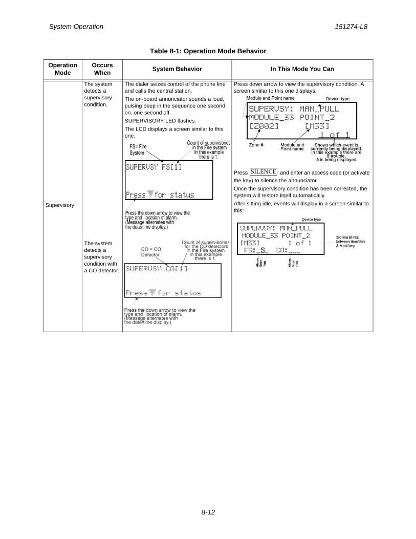
System Operation 151274-L8
8-12
Supervisory
The system detects a supervisory condition.
The system detects a supervisory condition with a CO detector.
The dialer seizes control of the phone line and calls the central station.
The on-board annunciator sounds a loud, pulsing beep in the sequence one second on, one second off.
SUPERVISORY LED flashes.
The LCD displays a screen similar to this one.
Press down arrow to view the supervisory condition. A screen similar to this one displays.
Press and enter an access code (or activate the key) to silence the annunciator.
Once the supervisory condition has been corrected, the system will restore itself automatically.
After sitting idle, events will display in a screen similar to this:
Table 8-1: Operation Mode Behavior
Operation Mode
Occurs When
System Behavior In This Mode You Can
SILENCE
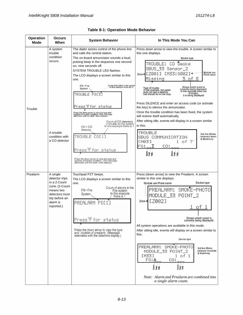
IntelliKnight 5808 Installation Manual 151274-L8
8-13
Trouble
A system trouble condition occurs.
A trouble condition with a CO detector
The dialer seizes control of the phone line and calls the central station.
The on-board annunciator sounds a loud, pulsing beep in the sequence one second on, nine seconds off.
SYSTEM TROUBLE LED flashes.
The LCD displays a screen similar to this one.
Press down arrow to view the trouble. A screen similar to this one displays.
Press SILENCE and enter an access code (or activate the key) to silence the annunciator.
Once the trouble condition has been fixed, the system will restore itself automatically.
After sitting idle, events will display in a screen similar
to this:
Prealarm A single detector trips in a 2-Count zone. (2-Count means two detectors must trip before an alarm is reported.)
Touchpad PZT beeps.
The LCD displays a screen similar to this one.
Press (down arrow) to view the Prealarm. A screen similar to this one displays.
All system operations are available in this mode.
After sitting idle, events will display on a screen similar to this:
Note: Alarm and Prealarm are combined into a single alarm count.
Table 8-1: Operation Mode Behavior
Operation Mode
Occurs When
System Behavior In This Mode You Can
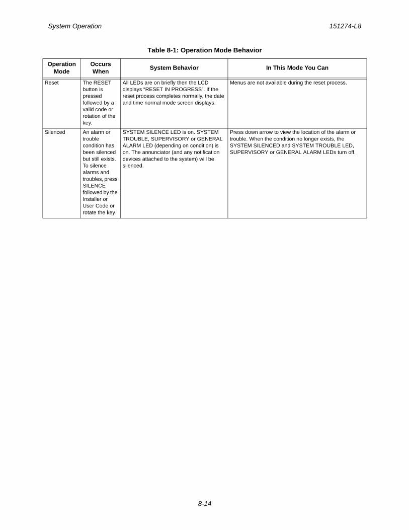
System Operation 151274-L8
8-14
Reset The RESET button is pressed followed by a valid code or rotation of the key.
All LEDs are on briefly then the LCD displays “RESET IN PROGRESS”. If the reset process completes normally, the date and time normal mode screen displays.
Menus are not available during the reset process.
Silenced An alarm or trouble condition has been silenced but still exists. To silence alarms and troubles, press SILENCE followed by the Installer or User Code or rotate the key.
SYSTEM SILENCE LED is on. SYSTEM TROUBLE, SUPERVISORY or GENERAL ALARM LED (depending on condition) is on. The annunciator (and any notification devices attached to the system) will be silenced.
Press down arrow to view the location of the alarm or trouble. When the condition no longer exists, the SYSTEM SILENCED and SYSTEM TROUBLE LED, SUPERVISORY or GENERAL ALARM LEDs turn off.
Table 8-1: Operation Mode Behavior
Operation Mode
Occurs When
System Behavior In This Mode You Can
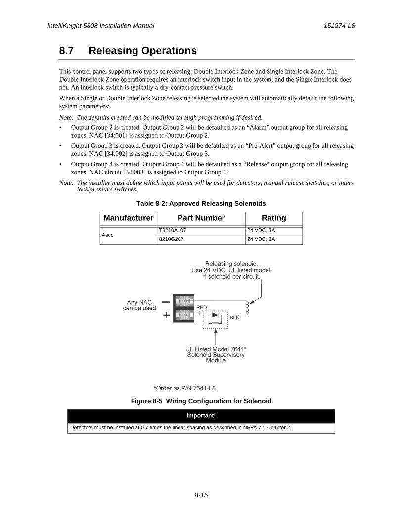
IntelliKnight 5808 Installation Manual 151274-L8
8-15
8.7 Releasing Operations
This control panel supports two types of releasing: Double Interlock Zone and Single Interlock Zone. The Double Interlock Zone operation requires an interlock switch input in the system, and the Single Interlock does not. An interlock switch is typically a dry-contact pressure switch.
When a Single or Double Interlock Zone releasing is selected the system will automatically default the following system parameters:
Note: The defaults created can be modified through programming if desired.
• Output Group 2 is created. Output Group 2 will be defaulted as an “Alarm” output group for all releasing zones. NAC [34:001] is assigned to Output Group 2.
• Output Group 3 is created. Output Group 3 will be defaulted as an “Pre-Alert” output group for all releasing zones. NAC [34:002] is assigned to Output Group 3.
• Output Group 4 is created. Output Group 4 will be defaulted as a “Release” output group for all releasing zones. NAC circuit [34:003] is assigned to Output Group 4.
Note: The installer must define which input points will be used for detectors, manual release switches, or inter-lock/pressure switches.
Figure 8-5 Wiring Configuration for Solenoid
Table 8-2: Approved Releasing Solenoids
Manufacturer Part Number Rating
AscoT8210A107 24 VDC, 3A
8210G207 24 VDC, 3A
Important!
Detectors must be installed at 0.7 times the linear spacing as described in NFPA 72, Chapter 2.
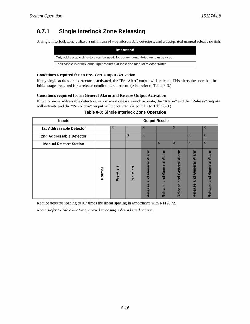
System Operation 151274-L8
8-16
8.7.1 Single Interlock Zone Releasing
A single interlock zone utilizes a minimum of two addressable detectors, and a designated manual release switch.
Conditions Required for an Pre-Alert Output ActivationIf any single addressable detector is activated, the “Pre-Alert” output will activate. This alerts the user that the initial stages required for a release condition are present. (Also refer to Table 8-3.)
Conditions required for an General Alarm and Release Output ActivationIf two or more addressable detectors, or a manual release switch activate, the “Alarm” and the “Release” outputs will activate and the “Pre-Alarm” output will deactivate. (Also refer to Table 8-3.)
Reduce detector spacing to 0.7 times the linear spacing in accordance with NFPA 72.
Note: Refer to Table 8-2 for approved releasing solenoids and ratings.
Important!
Only addressable detectors can be used. No conventional detectors can be used.
Each Single Interlock Zone input requires at least one manual release switch.
Table 8-3: Single Interlock Zone Operation
Inputs Output Results
1st Addressable Detector X X X X
2nd Addressable Detector X X X X
Manual Release Station X X X X
No
rmal
Pre
-Ale
rt
Pre
-Ale
rt
Rel
ease
an
d G
ener
al A
larm
Rel
ease
an
d G
ener
al A
larm
Rel
ease
an
d G
ener
al A
larm
Rel
ease
an
d G
ener
al A
larm
Rel
ease
an
d G
ener
al A
larm
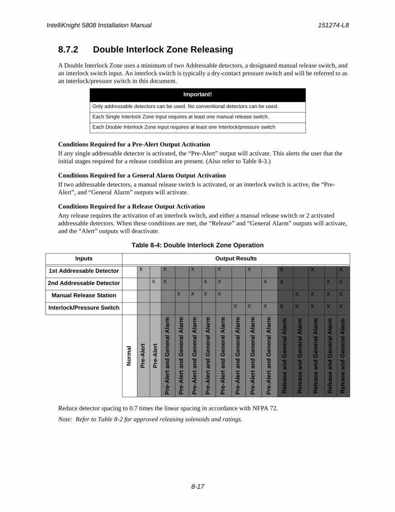
IntelliKnight 5808 Installation Manual 151274-L8
8-17
8.7.2 Double Interlock Zone Releasing
A Double Interlock Zone uses a minimum of two Addressable detectors, a designated manual release switch, and an interlock switch input. An interlock switch is typically a dry-contact pressure switch and will be referred to as an interlock/pressure switch in this document.
Conditions Required for a Pre-Alert Output ActivationIf any single addressable detector is activated, the “Pre-Alert” output will activate. This alerts the user that the initial stages required for a release condition are present. (Also refer to Table 8-3.)
Conditions Required for a General Alarm Output ActivationIf two addressable detectors, a manual release switch is activated, or an interlock switch is active, the “Pre-Alert”, and “General Alarm” outputs will activate.
Conditions Required for a Release Output ActivationAny release requires the activation of an interlock switch, and either a manual release switch or 2 activated addressable detectors. When these conditions are met, the “Release” and “General Alarm” outputs will activate, and the “Alert” outputs will deactivate.
Reduce detector spacing to 0.7 times the linear spacing in accordance with NFPA 72.
Note: Refer to Table 8-2 for approved releasing solenoids and ratings.
Important!
Only addressable detectors can be used. No conventional detectors can be used.
Each Single Interlock Zone input requires at least one manual release switch.
Each Double Interlock Zone input requires at least one Interlock/pressure switch
Table 8-4: Double Interlock Zone Operation
Inputs Output Results
1st Addressable Detector X X X X X X X X
2nd Addressable Detector X X X X X X X X
Manual Release Station X X X X X X X X
Interlock/Pressure Switch X X X X X X X X
No
rmal
Pre
-Ale
rt
Pre
-Ale
rt
Pre
-Ale
rt a
nd
Gen
eral
Ala
rm
Pre
-Ale
rt a
nd
Gen
eral
Ala
rm
Pre
-Ale
rt a
nd
Gen
eral
Ala
rm
Pre
-Ale
rt a
nd
Gen
eral
Ala
rm
Pre
-Ale
rt a
nd
Gen
eral
Ala
rm
Pre
-Ale
rt a
nd
Gen
eral
Ala
rm
Pre
-Ale
rt a
nd
Gen
eral
Ala
rm
Pre
-Ale
rt a
nd
Gen
eral
Ala
rm
Rel
ease
an
d G
ener
al A
larm
Rel
ease
an
d G
ener
al A
larm
Rel
ease
an
d G
ener
al A
larm
Rel
ease
an
d G
ener
al A
larm
Rel
ease
an
d G
ener
al A
larm
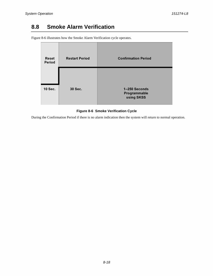
System Operation 151274-L8
8-18
8.8 Smoke Alarm Verification
Figure 8-6 illustrates how the Smoke Alarm Verification cycle operates.
Figure 8-6 Smoke Verification Cycle
During the Confirmation Period if there is no alarm indication then the system will return to normal operation.
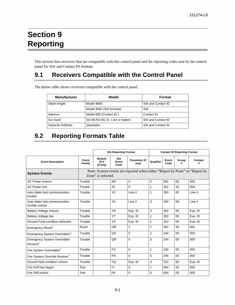
151274-L8
9-1
Section 9Reporting
This section lists receivers that are compatible with this control panel and the reporting codes sent by the control panel for SIA and Contact ID formats.
9.1 Receivers Compatible with the Control Panel
The below table shows receivers compatible with the control panel.
9.2 Reporting Formats Table
Manufacturer Model Format
Silent Knight Model 9800 SIA and Contact ID
Model 9000 (SIA formats) SIA
Ademco Model 685 (Contact ID ) Contact ID
Sur-Gard SG-MLR2-DG (V. 1.64 or higher) SIA and Contact ID
Osborne Hoffman Quickalert SIA and Contact ID
SIA Reporting Format Contact ID Reporting Format
Event Description Event Family
ModuleID #
(if any)
SIAEventCode
Parameter (if any) Qualifier Event
CodeGroup
#Contact
#
System Events Note: System events are reported when either “Report by Point” or “Report by Zone” is selected.
AC Power restore Trouble AR 0 3 301 00 000
AC Power lost Trouble AT 0 1 301 00 000
Auto dialer test communication trouble
Trouble YC Line # 1 350 00 Line #
Auto dialer test communication trouble restore
Trouble YK Line # 3 350 00 Line #
Battery Voltage restore Trouble YR Exp. ID 3 302 00 Exp. ID
Battery Voltage low Trouble YT Exp. ID 1 302 00 Exp. ID
Ground Fault condition detected Trouble YP Exp. ID 1 310 00 Exp. ID
Emergency Reset1 Reset OR 1 1 401 00 001
Emergency System Overridden1 Trouble QS 0 1 244 00 000
Emergency System Overridden
Restore1Trouble QR 0 3 244 00 000
Fire System Overridden1 Trouble FS 0 1 245 00 000
Fire System Override Restore1 Trouble FR 0 3 245 00 000
Ground fault condition restore Trouble YQ Exp. ID 3 310 00 Exp. ID
Fire Drill has begun Test FI 0 1 604 00 000
Fire Drill ended Test FK 0 3 604 00 000
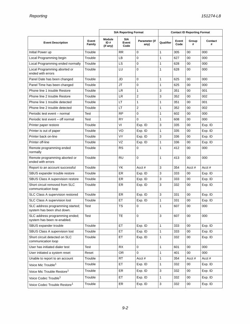
Reporting 151274-L8
9-2
Initial Power up Trouble RR 0 1 305 00 000
Local Programming begin Trouble LB 0 1 627 00 000
Local Programming ended normally Trouble LS 0 1 628 00 000
Local Programming aborted or ended with errors
Trouble LU 0 1 628 00 000
Panel Date has been changed Trouble JD 0 1 625 00 000
Panel Time has been changed Trouble JT 0 1 625 00 000
Phone line 1 trouble Restore Trouble LR 1 3 351 00 001
Phone line 2 trouble Restore Trouble LR 2 3 352 00 002
Phone line 1 trouble detected Trouble LT 1 1 351 00 001
Phone line 2 trouble detected Trouble LT 2 1 352 00 002
Periodic test event – normal Test RP 0 1 602 00 000
Periodic test event – off normal Test RY 0 1 608 00 000
Printer paper restore Trouble VI Exp. ID 3 335 00 Exp. ID
Printer is out of paper Trouble VO Exp. ID 1 335 00 Exp. ID
Printer back on-line Trouble VY Exp. ID 3 336 00 Exp. ID
Printer off-line Trouble VZ Exp. ID 1 336 00 Exp. ID
Remote programming ended normally
Trouble RS 0 1 412 00 000
Remote programming aborted or ended with errors
Trouble RU 0 1 413 00 000
Report to an account successful Trouble YK Acct # 3 354 Acct # Acct #
SBUS expander trouble restore Trouble ER Exp. ID 3 333 00 Exp. ID
SBUS Class A supervision restore Trouble ER Exp. ID 3 333 00 Exp. ID
Short circuit removed from SLC communication loop
Trouble ER Exp. ID 3 332 00 Exp. ID
SLC Class A supervision restored Trouble ER Exp. ID 3 331 00 Exp. ID
SLC Class A supervision lost Trouble ET Exp. ID 1 331 00 Exp. ID
SLC address programming started; system has been shut down.
Test TS 0 1 607 00 000
SLC address programming ended; system has been re-enabled.
Test TE 0 3 607 00 000
SBUS expander trouble Trouble ET Exp. ID 1 333 00 Exp. ID
SBUS Class A supervision lost Trouble ET Exp. ID 1 333 00 Exp. ID
Short circuit detected on SLC communication loop
Trouble ET Exp. ID 1 332 00 Exp. ID
User has initiated dialer test Test RX 0 1 601 00 000
User initiated a system reset Reset OR 0 1 401 00 000
Unable to report to an account Trouble RT Acct # 1 354 Acct # Acct #
Voice Mic Trouble1 Trouble ET Exp. ID 1 332 00 Exp. ID
Voice Mic Trouble Restore1 Trouble ER Exp. ID 3 332 00 Exp. ID
Voice Codec Trouble1 Trouble ET Exp. ID 1 332 00 Exp. ID
Voice Codec Trouble Restore1 Trouble ER Exp. ID 3 332 00 Exp. ID
SIA Reporting Format Contact ID Reporting Format
Event Description Event Family
ModuleID #
(if any)
SIAEventCode
Parameter (if any) Qualifier Event
CodeGroup
#Contact
#
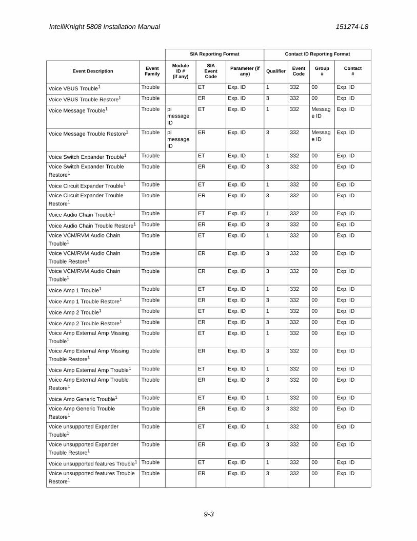
IntelliKnight 5808 Installation Manual 151274-L8
9-3
Voice VBUS Trouble1 Trouble ET Exp. ID 1 332 00 Exp. ID
Voice VBUS Trouble Restore1 Trouble ER Exp. ID 3 332 00 Exp. ID
Voice Message Trouble1 Trouble pi message ID
ET Exp. ID 1 332 Message ID
Exp. ID
Voice Message Trouble Restore1 Trouble pi message ID
ER Exp. ID 3 332 Message ID
Exp. ID
Voice Switch Expander Trouble1 Trouble ET Exp. ID 1 332 00 Exp. ID
Voice Switch Expander Trouble
Restore1Trouble ER Exp. ID 3 332 00 Exp. ID
Voice Circuit Expander Trouble1 Trouble ET Exp. ID 1 332 00 Exp. ID
Voice Circuit Expander Trouble
Restore1Trouble ER Exp. ID 3 332 00 Exp. ID
Voice Audio Chain Trouble1 Trouble ET Exp. ID 1 332 00 Exp. ID
Voice Audio Chain Trouble Restore1 Trouble ER Exp. ID 3 332 00 Exp. ID
Voice VCM/RVM Audio Chain
Trouble1Trouble ET Exp. ID 1 332 00 Exp. ID
Voice VCM/RVM Audio Chain
Trouble Restore1Trouble ER Exp. ID 3 332 00 Exp. ID
Voice VCM/RVM Audio Chain
Trouble1Trouble ER Exp. ID 3 332 00 Exp. ID
Voice Amp 1 Trouble1 Trouble ET Exp. ID 1 332 00 Exp. ID
Voice Amp 1 Trouble Restore1 Trouble ER Exp. ID 3 332 00 Exp. ID
Voice Amp 2 Trouble1 Trouble ET Exp. ID 1 332 00 Exp. ID
Voice Amp 2 Trouble Restore1 Trouble ER Exp. ID 3 332 00 Exp. ID
Voice Amp External Amp Missing
Trouble1Trouble ET Exp. ID 1 332 00 Exp. ID
Voice Amp External Amp Missing
Trouble Restore1Trouble ER Exp. ID 3 332 00 Exp. ID
Voice Amp External Amp Trouble1 Trouble ET Exp. ID 1 332 00 Exp. ID
Voice Amp External Amp Trouble
Restore1Trouble ER Exp. ID 3 332 00 Exp. ID
Voice Amp Generic Trouble1 Trouble ET Exp. ID 1 332 00 Exp. ID
Voice Amp Generic Trouble
Restore1Trouble ER Exp. ID 3 332 00 Exp. ID
Voice unsupported Expander
Trouble1Trouble ET Exp. ID 1 332 00 Exp. ID
Voice unsupported Expander
Trouble Restore1Trouble ER Exp. ID 3 332 00 Exp. ID
Voice unsupported features Trouble1 Trouble ET Exp. ID 1 332 00 Exp. ID
Voice unsupported features Trouble
Restore1Trouble ER Exp. ID 3 332 00 Exp. ID
SIA Reporting Format Contact ID Reporting Format
Event Description Event Family
ModuleID #
(if any)
SIAEventCode
Parameter (if any) Qualifier Event
CodeGroup
#Contact
#
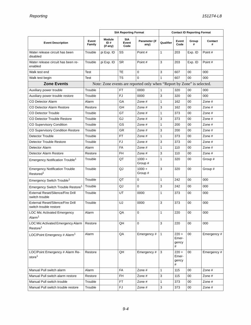
Reporting 151274-L8
9-4
Water release circuit has been disabled
Trouble pi Exp. ID SS Point # 1 203 Exp. ID Point #
Water release circuit has been re-enabled
Trouble pi Exp. ID SR Point # 3 203 Exp. ID Point #
Walk test end Test TE 0 3 607 00 000
Walk test begin Test TS 0 1 607 00 000
Zone Events Note: Zone events are reported only when “Report by Zone” is selected.
Auxiliary power trouble Trouble FT 0000 1 320 00 000
Auxiliary power trouble restore Trouble FJ 0000 3 320 00 000
CO Detector Alarm Alarm GA Zone # 1 162 00 Zone #
CO Detector Alarm Restore Restore GH Zone # 3 162 00 Zone #
CO Detector Trouble Trouble GT Zone # 1 373 00 Zone #
CO Detector Trouble Restore Trouble GJ Zone # 3 373 00 Zone #
CO Supervisory Condition Trouble GS Zone # 1 200 00 Zone #
CO Supervisory Condition Restore Trouble GR Zone # 3 200 00 Zone #
Detector Trouble Trouble FT Zone # 1 373 00 Zone #
Detector Trouble Restore Trouble FJ Zone # 3 373 00 Zone #
Detector Alarm Alarm FA Zone # 1 110 00 Zone #
Detector Alarm Restore Restore FH Zone # 3 110 00 Zone #
Emergency Notification Trouble1 Trouble QT 1000 + Group #
1 320 00 Group #
Emergency Notification Trouble
Restored1Trouble QJ 1000 +
Group #3 320 00 Group #
Emergency Switch Trouble1 Trouble QT 0 1 242 00 000
Emergency Switch Trouble Restore1 Trouble QJ 0 3 242 00 000
External Reset/Silence/Fire Drill switch trouble
Trouble UT 0000 1 373 00 000
External Reset/Silence/Fire Drill switch trouble restore
Trouble UJ 0000 3 373 00 000
LOC Mic Activated Emergency
Alarm1Alarm QA 0 1 220 00 000
LOC Mic Activated Emergency Alarm
Restore1Restore QH 0 3 220 00 000
LOC/Point Emergency # Alarm1 Alarm QA Emergency # 1 220 + Emer-gency #
00 Emergency #
LOC/Point Emergency # Alarm Re-
store1Restore QH Emergency # 3 220 +
Emer-gency #
00 Emergency #
Manual Pull switch alarm Alarm FA Zone # 1 115 00 Zone #
Manual Pull switch alarm restore Restore FH Zone # 3 115 00 Zone #
Manual Pull switch trouble Trouble FT Zone # 1 373 00 Zone #
Manual Pull switch trouble restore Trouble FJ Zone # 3 373 00 Zone #
SIA Reporting Format Contact ID Reporting Format
Event Description Event Family
ModuleID #
(if any)
SIAEventCode
Parameter (if any) Qualifier Event
CodeGroup
#Contact
#
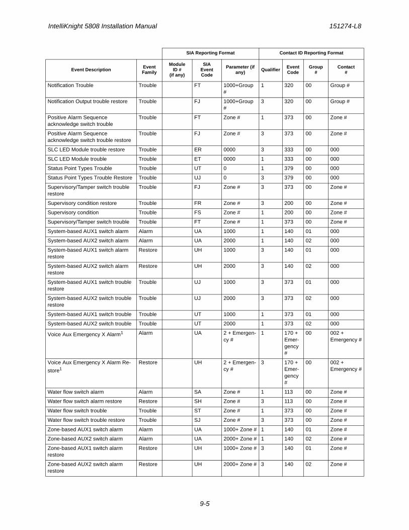
IntelliKnight 5808 Installation Manual 151274-L8
9-5
Notification Trouble Trouble FT 1000+Group #
1 320 00 Group #
Notification Output trouble restore Trouble FJ 1000+Group #
3 320 00 Group #
Positive Alarm Sequence acknowledge switch trouble
Trouble FT Zone # 1 373 00 Zone #
Positive Alarm Sequence acknowledge switch trouble restore
Trouble FJ Zone # 3 373 00 Zone #
SLC LED Module trouble restore Trouble ER 0000 3 333 00 000
SLC LED Module trouble Trouble ET 0000 1 333 00 000
Status Point Types Trouble Trouble UT 0 1 379 00 000
Status Point Types Trouble Restore Trouble UJ 0 3 379 00 000
Supervisory/Tamper switch trouble restore
Trouble FJ Zone # 3 373 00 Zone #
Supervisory condition restore Trouble FR Zone # 3 200 00 Zone #
Supervisory condition Trouble FS Zone # 1 200 00 Zone #
Supervisory/Tamper switch trouble Trouble FT Zone # 1 373 00 Zone #
System-based AUX1 switch alarm Alarm UA 1000 1 140 01 000
System-based AUX2 switch alarm Alarm UA 2000 1 140 02 000
System-based AUX1 switch alarm restore
Restore UH 1000 3 140 01 000
System-based AUX2 switch alarm restore
Restore UH 2000 3 140 02 000
System-based AUX1 switch trouble restore
Trouble UJ 1000 3 373 01 000
System-based AUX2 switch trouble restore
Trouble UJ 2000 3 373 02 000
System-based AUX1 switch trouble Trouble UT 1000 1 373 01 000
System-based AUX2 switch trouble Trouble UT 2000 1 373 02 000
Voice Aux Emergency X Alarm1 Alarm UA 2 + Emergen-cy #
1 170 + Emer-gency #
00 002 + Emergency #
Voice Aux Emergency X Alarm Re-
store1Restore UH 2 + Emergen-
cy #3 170 +
Emer-gency #
00 002 + Emergency #
Water flow switch alarm Alarm SA Zone # 1 113 00 Zone #
Water flow switch alarm restore Restore SH Zone # 3 113 00 Zone #
Water flow switch trouble Trouble ST Zone # 1 373 00 Zone #
Water flow switch trouble restore Trouble SJ Zone # 3 373 00 Zone #
Zone-based AUX1 switch alarm Alarm UA 1000+ Zone # 1 140 01 Zone #
Zone-based AUX2 switch alarm Alarm UA 2000+ Zone # 1 140 02 Zone #
Zone-based AUX1 switch alarm restore
Restore UH 1000+ Zone # 3 140 01 Zone #
Zone-based AUX2 switch alarm restore
Restore UH 2000+ Zone # 3 140 02 Zone #
SIA Reporting Format Contact ID Reporting Format
Event Description Event Family
ModuleID #
(if any)
SIAEventCode
Parameter (if any) Qualifier Event
CodeGroup
#Contact
#
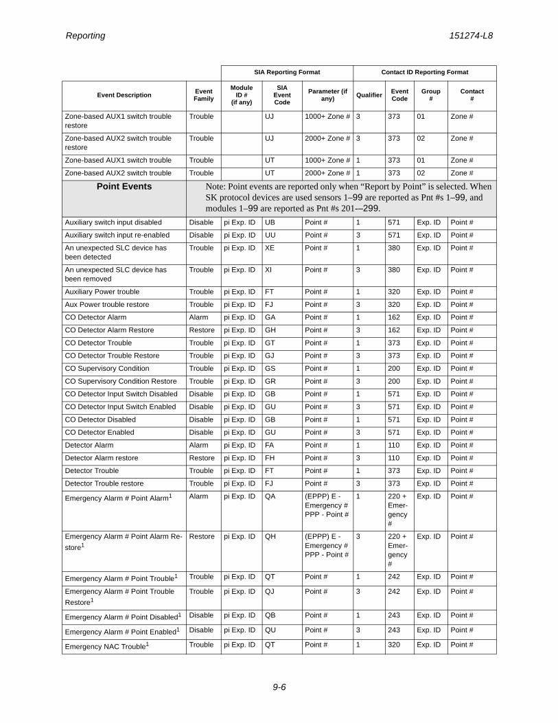
Reporting 151274-L8
9-6
Zone-based AUX1 switch trouble restore
Trouble UJ 1000+ Zone # 3 373 01 Zone #
Zone-based AUX2 switch trouble restore
Trouble UJ 2000+ Zone # 3 373 02 Zone #
Zone-based AUX1 switch trouble Trouble UT 1000+ Zone # 1 373 01 Zone #
Zone-based AUX2 switch trouble Trouble UT 2000+ Zone # 1 373 02 Zone #
Point Events Note: Point events are reported only when “Report by Point” is selected. When SK protocol devices are used sensors 1–99 are reported as Pnt #s 1–99, and modules 1–99 are reported as Pnt #s 201-–299.
Auxiliary switch input disabled Disable pi Exp. ID UB Point # 1 571 Exp. ID Point #
Auxiliary switch input re-enabled Disable pi Exp. ID UU Point # 3 571 Exp. ID Point #
An unexpected SLC device has been detected
Trouble pi Exp. ID XE Point # 1 380 Exp. ID Point #
An unexpected SLC device has been removed
Trouble pi Exp. ID XI Point # 3 380 Exp. ID Point #
Auxiliary Power trouble Trouble pi Exp. ID FT Point # 1 320 Exp. ID Point #
Aux Power trouble restore Trouble pi Exp. ID FJ Point # 3 320 Exp. ID Point #
CO Detector Alarm Alarm pi Exp. ID GA Point # 1 162 Exp. ID Point #
CO Detector Alarm Restore Restore pi Exp. ID GH Point # 3 162 Exp. ID Point #
CO Detector Trouble Trouble pi Exp. ID GT Point # 1 373 Exp. ID Point #
CO Detector Trouble Restore Trouble pi Exp. ID GJ Point # 3 373 Exp. ID Point #
CO Supervisory Condition Trouble pi Exp. ID GS Point # 1 200 Exp. ID Point #
CO Supervisory Condition Restore Trouble pi Exp. ID GR Point # 3 200 Exp. ID Point #
CO Detector Input Switch Disabled Disable pi Exp. ID GB Point # 1 571 Exp. ID Point #
CO Detector Input Switch Enabled Disable pi Exp. ID GU Point # 3 571 Exp. ID Point #
CO Detector Disabled Disable pi Exp. ID GB Point # 1 571 Exp. ID Point #
CO Detector Enabled Disable pi Exp. ID GU Point # 3 571 Exp. ID Point #
Detector Alarm Alarm pi Exp. ID FA Point # 1 110 Exp. ID Point #
Detector Alarm restore Restore pi Exp. ID FH Point # 3 110 Exp. ID Point #
Detector Trouble Trouble pi Exp. ID FT Point # 1 373 Exp. ID Point #
Detector Trouble restore Trouble pi Exp. ID FJ Point # 3 373 Exp. ID Point #
Emergency Alarm # Point Alarm1 Alarm pi Exp. ID QA (EPPP) E - Emergency #PPP - Point #
1 220 + Emer-gency #
Exp. ID Point #
Emergency Alarm # Point Alarm Re-
store1Restore pi Exp. ID QH (EPPP) E -
Emergency #PPP - Point #
3 220 + Emer-gency #
Exp. ID Point #
Emergency Alarm # Point Trouble1 Trouble pi Exp. ID QT Point # 1 242 Exp. ID Point #
Emergency Alarm # Point Trouble
Restore1Trouble pi Exp. ID QJ Point # 3 242 Exp. ID Point #
Emergency Alarm # Point Disabled1 Disable pi Exp. ID QB Point # 1 243 Exp. ID Point #
Emergency Alarm # Point Enabled1 Disable pi Exp. ID QU Point # 3 243 Exp. ID Point #
Emergency NAC Trouble1 Trouble pi Exp. ID QT Point # 1 320 Exp. ID Point #
SIA Reporting Format Contact ID Reporting Format
Event Description Event Family
ModuleID #
(if any)
SIAEventCode
Parameter (if any) Qualifier Event
CodeGroup
#Contact
#
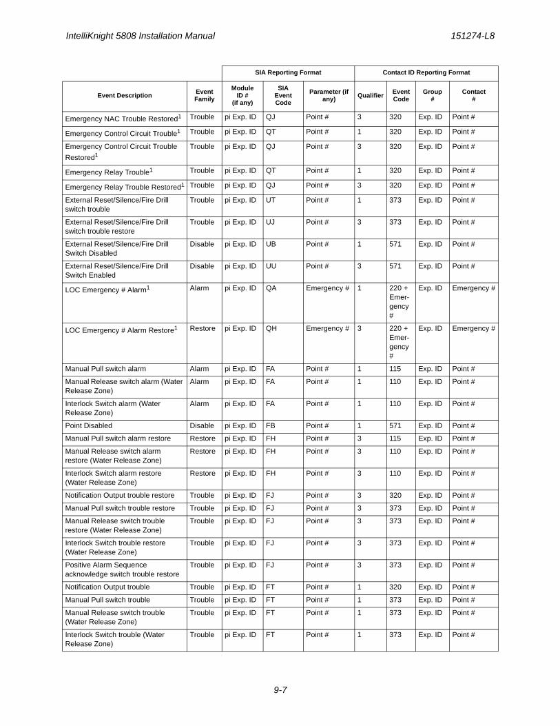
IntelliKnight 5808 Installation Manual 151274-L8
9-7
Emergency NAC Trouble Restored1 Trouble pi Exp. ID QJ Point # 3 320 Exp. ID Point #
Emergency Control Circuit Trouble1 Trouble pi Exp. ID QT Point # 1 320 Exp. ID Point #
Emergency Control Circuit Trouble
Restored1Trouble pi Exp. ID QJ Point # 3 320 Exp. ID Point #
Emergency Relay Trouble1 Trouble pi Exp. ID QT Point # 1 320 Exp. ID Point #
Emergency Relay Trouble Restored1 Trouble pi Exp. ID QJ Point # 3 320 Exp. ID Point #
External Reset/Silence/Fire Drill switch trouble
Trouble pi Exp. ID UT Point # 1 373 Exp. ID Point #
External Reset/Silence/Fire Drill switch trouble restore
Trouble pi Exp. ID UJ Point # 3 373 Exp. ID Point #
External Reset/Silence/Fire Drill Switch Disabled
Disable pi Exp. ID UB Point # 1 571 Exp. ID Point #
External Reset/Silence/Fire Drill Switch Enabled
Disable pi Exp. ID UU Point # 3 571 Exp. ID Point #
LOC Emergency # Alarm1 Alarm pi Exp. ID QA Emergency # 1 220 + Emer-gency #
Exp. ID Emergency #
LOC Emergency # Alarm Restore1 Restore pi Exp. ID QH Emergency # 3 220 + Emer-gency #
Exp. ID Emergency #
Manual Pull switch alarm Alarm pi Exp. ID FA Point # 1 115 Exp. ID Point #
Manual Release switch alarm (Water Release Zone)
Alarm pi Exp. ID FA Point # 1 110 Exp. ID Point #
Interlock Switch alarm (Water Release Zone)
Alarm pi Exp. ID FA Point # 1 110 Exp. ID Point #
Point Disabled Disable pi Exp. ID FB Point # 1 571 Exp. ID Point #
Manual Pull switch alarm restore Restore pi Exp. ID FH Point # 3 115 Exp. ID Point #
Manual Release switch alarm restore (Water Release Zone)
Restore pi Exp. ID FH Point # 3 110 Exp. ID Point #
Interlock Switch alarm restore (Water Release Zone)
Restore pi Exp. ID FH Point # 3 110 Exp. ID Point #
Notification Output trouble restore Trouble pi Exp. ID FJ Point # 3 320 Exp. ID Point #
Manual Pull switch trouble restore Trouble pi Exp. ID FJ Point # 3 373 Exp. ID Point #
Manual Release switch trouble restore (Water Release Zone)
Trouble pi Exp. ID FJ Point # 3 373 Exp. ID Point #
Interlock Switch trouble restore (Water Release Zone)
Trouble pi Exp. ID FJ Point # 3 373 Exp. ID Point #
Positive Alarm Sequence acknowledge switch trouble restore
Trouble pi Exp. ID FJ Point # 3 373 Exp. ID Point #
Notification Output trouble Trouble pi Exp. ID FT Point # 1 320 Exp. ID Point #
Manual Pull switch trouble Trouble pi Exp. ID FT Point # 1 373 Exp. ID Point #
Manual Release switch trouble (Water Release Zone)
Trouble pi Exp. ID FT Point # 1 373 Exp. ID Point #
Interlock Switch trouble (Water Release Zone)
Trouble pi Exp. ID FT Point # 1 373 Exp. ID Point #
SIA Reporting Format Contact ID Reporting Format
Event Description Event Family
ModuleID #
(if any)
SIAEventCode
Parameter (if any) Qualifier Event
CodeGroup
#Contact
#
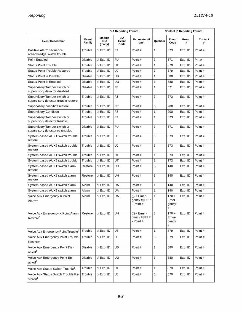
Reporting 151274-L8
9-8
Positive Alarm sequence acknowledge switch trouble
Trouble pi Exp. ID FT Point # 1 373 Exp. ID Point #
Point Enabled Disable pi Exp. ID FU Point # 3 571 Exp. ID Pnt #
Status Point Trouble Trouble pi Exp. ID UT Point # 1 379 Exp. ID Point #
Status Point Trouble Restored Trouble pi Exp. ID UJ Point # 3 379 Exp. ID Point #
Status Point is Disabled Disable pi Exp. ID UB Point # 1 580 Exp. ID Point #
Status Point is Enabled Disable pi Exp. ID UU Point # 3 580 Exp. ID Point #
Supervisory/Tamper switch or supervisory detector disabled
Disable pi Exp. ID FB Point # 1 571 Exp. ID Point #
Supervisory/Tamper switch or supervisory detector trouble restore
Trouble pi Exp. ID FJ Point # 3 373 Exp. ID Point #
Supervisory condition restore Trouble pi Exp. ID FR Point # 3 200 Exp. ID Point #
Supervisory Condition Trouble pi Exp. ID FS Point # 1 200 Exp. ID Point #
Supervisory/Tamper switch or supervisory detector trouble
Trouble pi Exp. ID FT Point # 1 373 Exp. ID Point #
Supervisory/Tamper switch or supervisory detector re-enabled
Disable pi Exp. ID FU Point # 3 571 Exp. ID Point #
System-based AUX1 switch trouble restore
Trouble pi Exp. ID UJ Point # 3 373 Exp. ID Point #
System-based AUX2 switch trouble restore
Trouble pi Exp. ID UJ Point # 3 373 Exp. ID Point #
System-based AUX1 switch trouble Trouble pi Exp. ID UT Point # 1 373 Exp. ID Point #
System-based AUX2 switch trouble Trouble pi Exp. ID UT Point # 1 373 Exp. ID Point #
System-based AUX1 switch alarm restore
Restore pi Exp. ID UH Point # 3 140 Exp. ID Point #
System-based AUX2 switch alarm restore
Restore pi Exp. ID UH Point # 3 140 Exp. ID Point #
System-based AUX1 switch alarm Alarm pi Exp. ID UA Point # 1 140 Exp. ID Point #
System-based AUX2 switch alarm Alarm pi Exp. ID UA Point # 1 140 Exp. ID Point #
Voice Aux Emergency X Point
Alarm1Alarm pi Exp. ID UA ([2+ Emer-
gency #] PPP - Point #
1 170 + Emer-gency #
Exp. ID Point #
Voice Aux Emergency X Point Alarm
Restore1Restore pi Exp. ID UH ([2+ Emer-
gency #] PPP - Point #
3 170 + Emer-gency #
Exp. ID Point #
Voice Aux Emergency Point Trouble1 Trouble pi Exp. ID UT Point # 1 379 Exp. ID Point #
Voice Aux Emergency Point Trouble
Restore1Trouble pi Exp. ID UJ Point # 3 379 Exp. ID Point #
Voice Aux Emergency Point Dis-
abled1Disable pi Exp. ID UB Point # 1 580 Exp. ID Point #
Voice Aux Emergency Point En-
abled1Disable pi Exp. ID UU Point # 3 580 Exp. ID Point #
Voice Aux Status Switch Trouble1 Trouble pi Exp. ID UT Point # 1 379 Exp. ID Point #
Voice Aux Status Switch Trouble Re-
stored1Trouble pi Exp. ID UJ Point # 3 379 Exp. ID Point #
SIA Reporting Format Contact ID Reporting Format
Event Description Event Family
ModuleID #
(if any)
SIAEventCode
Parameter (if any) Qualifier Event
CodeGroup
#Contact
#
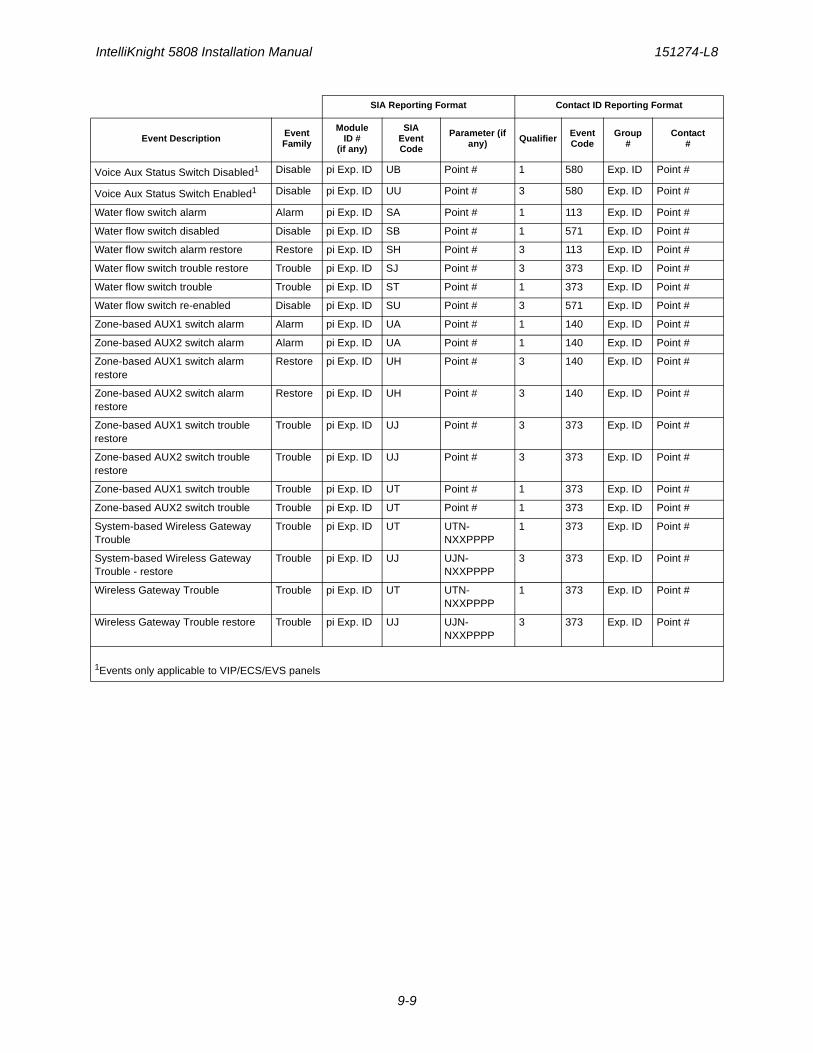
IntelliKnight 5808 Installation Manual 151274-L8
9-9
Voice Aux Status Switch Disabled1 Disable pi Exp. ID UB Point # 1 580 Exp. ID Point #
Voice Aux Status Switch Enabled1 Disable pi Exp. ID UU Point # 3 580 Exp. ID Point #
Water flow switch alarm Alarm pi Exp. ID SA Point # 1 113 Exp. ID Point #
Water flow switch disabled Disable pi Exp. ID SB Point # 1 571 Exp. ID Point #
Water flow switch alarm restore Restore pi Exp. ID SH Point # 3 113 Exp. ID Point #
Water flow switch trouble restore Trouble pi Exp. ID SJ Point # 3 373 Exp. ID Point #
Water flow switch trouble Trouble pi Exp. ID ST Point # 1 373 Exp. ID Point #
Water flow switch re-enabled Disable pi Exp. ID SU Point # 3 571 Exp. ID Point #
Zone-based AUX1 switch alarm Alarm pi Exp. ID UA Point # 1 140 Exp. ID Point #
Zone-based AUX2 switch alarm Alarm pi Exp. ID UA Point # 1 140 Exp. ID Point #
Zone-based AUX1 switch alarm restore
Restore pi Exp. ID UH Point # 3 140 Exp. ID Point #
Zone-based AUX2 switch alarm restore
Restore pi Exp. ID UH Point # 3 140 Exp. ID Point #
Zone-based AUX1 switch trouble restore
Trouble pi Exp. ID UJ Point # 3 373 Exp. ID Point #
Zone-based AUX2 switch trouble restore
Trouble pi Exp. ID UJ Point # 3 373 Exp. ID Point #
Zone-based AUX1 switch trouble Trouble pi Exp. ID UT Point # 1 373 Exp. ID Point #
Zone-based AUX2 switch trouble Trouble pi Exp. ID UT Point # 1 373 Exp. ID Point #
System-based Wireless Gateway Trouble
Trouble pi Exp. ID UT UTN-NXXPPPP
1 373 Exp. ID Point #
System-based Wireless Gateway Trouble - restore
Trouble pi Exp. ID UJ UJN-NXXPPPP
3 373 Exp. ID Point #
Wireless Gateway Trouble Trouble pi Exp. ID UT UTN-NXXPPPP
1 373 Exp. ID Point #
Wireless Gateway Trouble restore Trouble pi Exp. ID UJ UJN-NXXPPPP
3 373 Exp. ID Point #
1Events only applicable to VIP/ECS/EVS panels
SIA Reporting Format Contact ID Reporting Format
Event Description Event Family
ModuleID #
(if any)
SIAEventCode
Parameter (if any) Qualifier Event
CodeGroup
#Contact
#
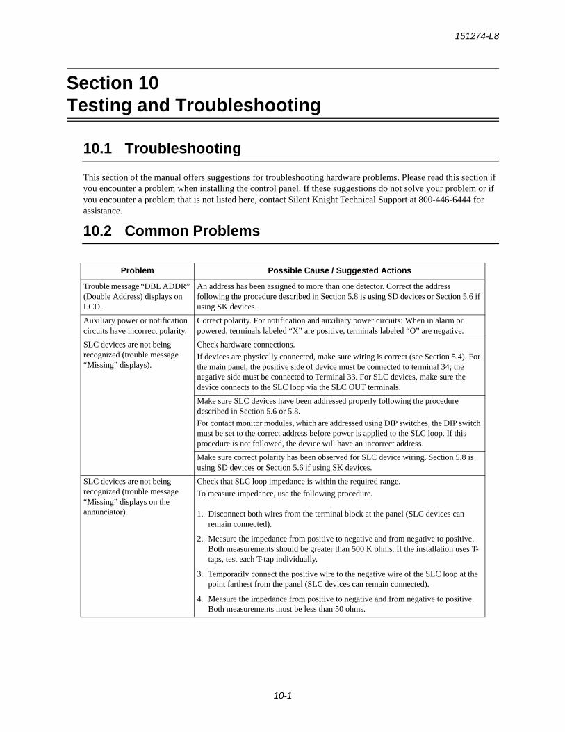
151274-L8
10-1
Section 10Testing and Troubleshooting
10.1 Troubleshooting
This section of the manual offers suggestions for troubleshooting hardware problems. Please read this section if you encounter a problem when installing the control panel. If these suggestions do not solve your problem or if you encounter a problem that is not listed here, contact Silent Knight Technical Support at 800-446-6444 for assistance.
10.2 Common Problems
Problem Possible Cause / Suggested Actions
Trouble message “DBL ADDR” (Double Address) displays on LCD.
An address has been assigned to more than one detector. Correct the address following the procedure described in Section 5.8 is using SD devices or Section 5.6 if using SK devices.
Auxiliary power or notification circuits have incorrect polarity.
Correct polarity. For notification and auxiliary power circuits: When in alarm or powered, terminals labeled “X” are positive, terminals labeled “O” are negative.
SLC devices are not being recognized (trouble message “Missing” displays).
Check hardware connections.
If devices are physically connected, make sure wiring is correct (see Section 5.4). For the main panel, the positive side of device must be connected to terminal 34; the negative side must be connected to Terminal 33. For SLC devices, make sure the device connects to the SLC loop via the SLC OUT terminals.
Make sure SLC devices have been addressed properly following the procedure described in Section 5.6 or 5.8.
For contact monitor modules, which are addressed using DIP switches, the DIP switch must be set to the correct address before power is applied to the SLC loop. If this procedure is not followed, the device will have an incorrect address.
Make sure correct polarity has been observed for SLC device wiring. Section 5.8 is using SD devices or Section 5.6 if using SK devices.
SLC devices are not being recognized (trouble message “Missing” displays on the annunciator).
Check that SLC loop impedance is within the required range.
To measure impedance, use the following procedure.
1. Disconnect both wires from the terminal block at the panel (SLC devices can remain connected).
2. Measure the impedance from positive to negative and from negative to positive. Both measurements should be greater than 500 K ohms. If the installation uses T-taps, test each T-tap individually.
3. Temporarily connect the positive wire to the negative wire of the SLC loop at the point farthest from the panel (SLC devices can remain connected).
4. Measure the impedance from positive to negative and from negative to positive. Both measurements must be less than 50 ohms.
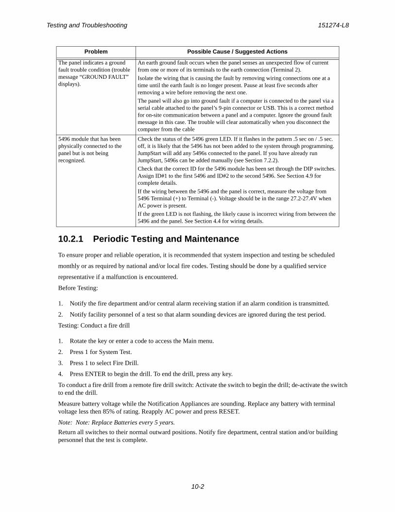
Testing and Troubleshooting 151274-L8
10-2
10.2.1 Periodic Testing and Maintenance
To ensure proper and reliable operation, it is recommended that system inspection and testing be scheduled
monthly or as required by national and/or local fire codes. Testing should be done by a qualified service
representative if a malfunction is encountered.
Before Testing:
1. Notify the fire department and/or central alarm receiving station if an alarm condition is transmitted.
2. Notify facility personnel of a test so that alarm sounding devices are ignored during the test period.
Testing: Conduct a fire drill
1. Rotate the key or enter a code to access the Main menu.
2. Press 1 for System Test.
3. Press 1 to select Fire Drill.
4. Press ENTER to begin the drill. To end the drill, press any key.
To conduct a fire drill from a remote fire drill switch: Activate the switch to begin the drill; de-activate the switch to end the drill.
Measure battery voltage while the Notification Appliances are sounding. Replace any battery with terminal voltage less then 85% of rating. Reapply AC power and press RESET.
Note: Note: Replace Batteries every 5 years.
Return all switches to their normal outward positions. Notify fire department, central station and/or building personnel that the test is complete.
The panel indicates a ground fault trouble condition (trouble message “GROUND FAULT” displays).
An earth ground fault occurs when the panel senses an unexpected flow of current from one or more of its terminals to the earth connection (Terminal 2).
Isolate the wiring that is causing the fault by removing wiring connections one at a time until the earth fault is no longer present. Pause at least five seconds after removing a wire before removing the next one.
The panel will also go into ground fault if a computer is connected to the panel via a serial cable attached to the panel’s 9-pin connector or USB. This is a correct method for on-site communication between a panel and a computer. Ignore the ground fault message in this case. The trouble will clear automatically when you disconnect the computer from the cable
5496 module that has been physically connected to the panel but is not being recognized.
Check the status of the 5496 green LED. If it flashes in the pattern .5 sec on / .5 sec. off, it is likely that the 5496 has not been added to the system through programming. JumpStart will add any 5496s connected to the panel. If you have already run JumpStart, 5496s can be added manually (see Section 7.2.2).
Check that the correct ID for the 5496 module has been set through the DIP switches. Assign ID#1 to the first 5496 and ID#2 to the second 5496. See Section 4.9 for complete details.
If the wiring between the 5496 and the panel is correct, measure the voltage from 5496 Terminal (+) to Terminal (-). Voltage should be in the range 27.2-27.4V when AC power is present.
If the green LED is not flashing, the likely cause is incorrect wiring from between the 5496 and the panel. See Section 4.4 for wiring details.
Problem Possible Cause / Suggested Actions
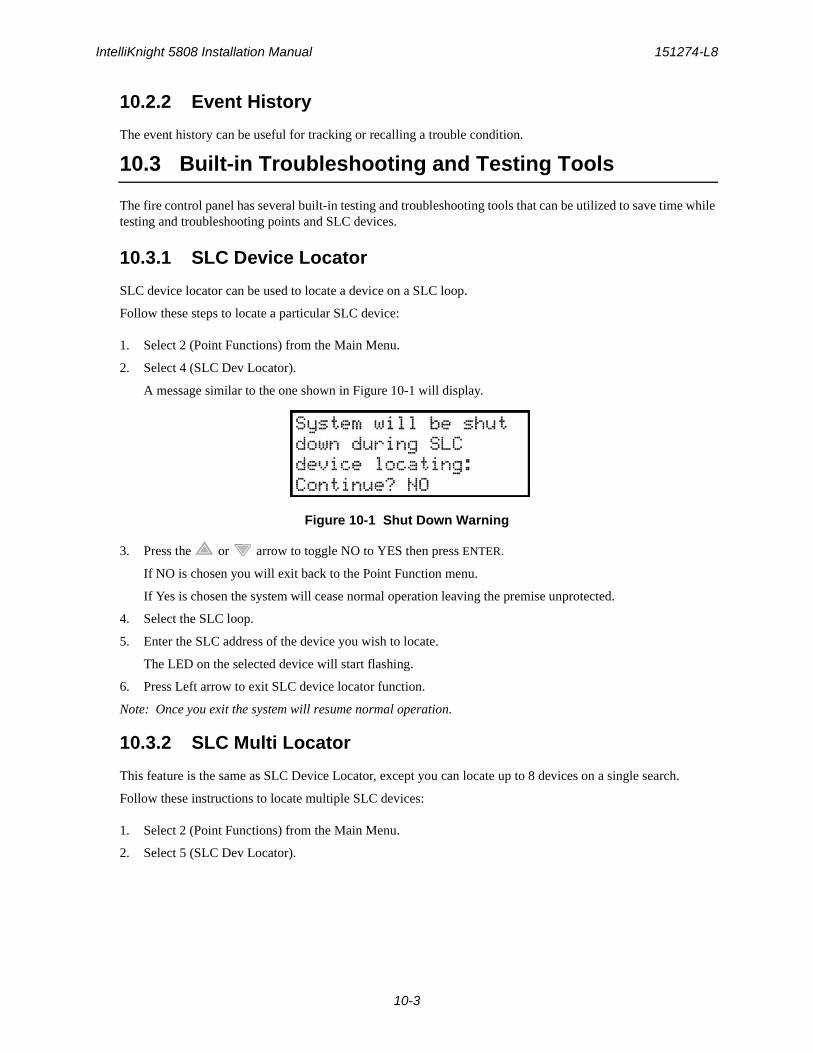
IntelliKnight 5808 Installation Manual 151274-L8
10-3
10.2.2 Event History
The event history can be useful for tracking or recalling a trouble condition.
10.3 Built-in Troubleshooting and Testing Tools
The fire control panel has several built-in testing and troubleshooting tools that can be utilized to save time while testing and troubleshooting points and SLC devices.
10.3.1 SLC Device Locator
SLC device locator can be used to locate a device on a SLC loop.
Follow these steps to locate a particular SLC device:
1. Select 2 (Point Functions) from the Main Menu.
2. Select 4 (SLC Dev Locator).
A message similar to the one shown in Figure 10-1 will display.
Figure 10-1 Shut Down Warning
3. Press the or arrow to toggle NO to YES then press ENTER.
If NO is chosen you will exit back to the Point Function menu.
If Yes is chosen the system will cease normal operation leaving the premise unprotected.
4. Select the SLC loop.
5. Enter the SLC address of the device you wish to locate.
The LED on the selected device will start flashing.
6. Press Left arrow to exit SLC device locator function.
Note: Once you exit the system will resume normal operation.
10.3.2 SLC Multi Locator
This feature is the same as SLC Device Locator, except you can locate up to 8 devices on a single search.
Follow these instructions to locate multiple SLC devices:
1. Select 2 (Point Functions) from the Main Menu.
2. Select 5 (SLC Dev Locator).
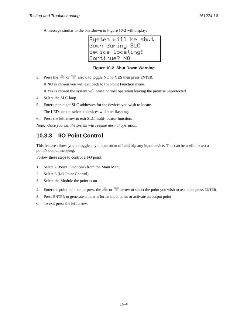
Testing and Troubleshooting 151274-L8
10-4
A message similar to the one shown in Figure 10-2 will display.
Figure 10-2 Shut Down Warning
3. Press the or arrow to toggle NO to YES then press ENTER.
If NO is chosen you will exit back to the Point Function menu.
If Yes is chosen the system will cease normal operation leaving the premise unprotected.
4. Select the SLC loop.
5. Enter up to eight SLC addresses for the devices you wish to locate.
The LEDs on the selected devices will start flashing.
6. Press the left arrow to exit SLC multi-locator function.
Note: Once you exit the system will resume normal operation.
10.3.3 I/O Point Control
This feature allows you to toggle any output on or off and trip any input device. This can be useful to test a point’s output mapping.
Follow these steps to control a I/O point:
1. Select 2 (Point Functions) from the Main Menu.
2. Select 6 (I/O Point Control).
3. Select the Module the point is on.
4. Enter the point number, or press the or arrow to select the point you wish to test, then press ENTER.
5. Press ENTER to generate an alarm for an input point or activate an output point.
6. To exit press the left arrow.

IntelliKnight 5808 Installation Manual 151274-L8
10-5
10.4 Impedances that Cause Earth Ground Faults
Table 10-1 show the minimum impedances that cause an earth ground fault on this system.
Table 10-1: Earth Ground Faults in Ohms
TERMINAL LOW BIASED HIGH BIASED
(values in kohms) high trip high restore low trip low restore
NAC 1 - 0 0
NAC 1 + 0 0
NAC 2 - 0 0
NAC 2 + 0 0
NAC 3 - 0 0
NAC 3 + 0 0
NAC 4 - 0 0
NAC 4 + 0 0
SBUS - 0 0
SBUS + 0 0
SBUS A 0 0
SBUS B 0 0
SLC IN - 0 0
SLC IN + 0 0
SLC OUT - 0 0
SLC OUT + 0 0
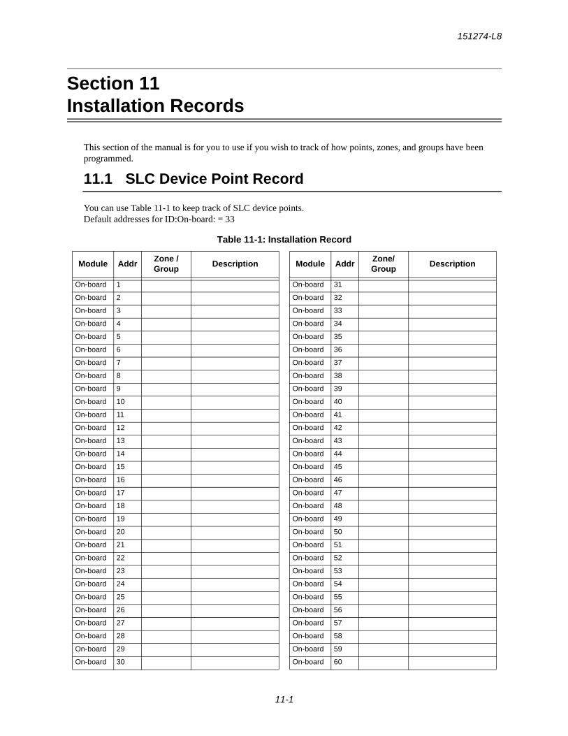
151274-L8
11-1
Section 11Installation Records
This section of the manual is for you to use if you wish to track of how points, zones, and groups have been programmed.
11.1 SLC Device Point Record
You can use Table 11-1 to keep track of SLC device points. Default addresses for ID:On-board: = 33
Table 11-1: Installation Record
Module AddrZone / Group
Description Module AddrZone/ Group
Description
On-board 1 On-board 31
On-board 2 On-board 32
On-board 3 On-board 33
On-board 4 On-board 34
On-board 5 On-board 35
On-board 6 On-board 36
On-board 7 On-board 37
On-board 8 On-board 38
On-board 9 On-board 39
On-board 10 On-board 40
On-board 11 On-board 41
On-board 12 On-board 42
On-board 13 On-board 43
On-board 14 On-board 44
On-board 15 On-board 45
On-board 16 On-board 46
On-board 17 On-board 47
On-board 18 On-board 48
On-board 19 On-board 49
On-board 20 On-board 50
On-board 21 On-board 51
On-board 22 On-board 52
On-board 23 On-board 53
On-board 24 On-board 54
On-board 25 On-board 55
On-board 26 On-board 56
On-board 27 On-board 57
On-board 28 On-board 58
On-board 29 On-board 59
On-board 30 On-board 60
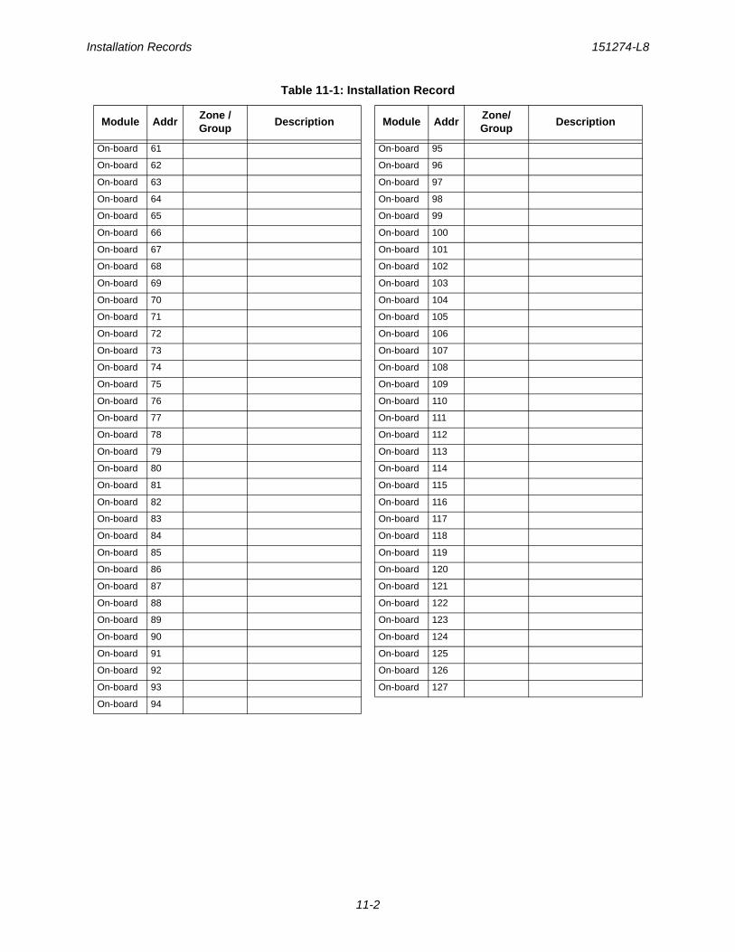
Installation Records 151274-L8
11-2
On-board 61 On-board 95
On-board 62 On-board 96
On-board 63 On-board 97
On-board 64 On-board 98
On-board 65 On-board 99
On-board 66 On-board 100
On-board 67 On-board 101
On-board 68 On-board 102
On-board 69 On-board 103
On-board 70 On-board 104
On-board 71 On-board 105
On-board 72 On-board 106
On-board 73 On-board 107
On-board 74 On-board 108
On-board 75 On-board 109
On-board 76 On-board 110
On-board 77 On-board 111
On-board 78 On-board 112
On-board 79 On-board 113
On-board 80 On-board 114
On-board 81 On-board 115
On-board 82 On-board 116
On-board 83 On-board 117
On-board 84 On-board 118
On-board 85 On-board 119
On-board 86 On-board 120
On-board 87 On-board 121
On-board 88 On-board 122
On-board 89 On-board 123
On-board 90 On-board 124
On-board 91 On-board 125
On-board 92 On-board 126
On-board 93 On-board 127
On-board 94
Table 11-1: Installation Record
Module AddrZone / Group
Description Module AddrZone/ Group
Description

151274-L8
A-1
Appendix ACompatible Devices
A.1 Notification Appliances
For proper operation, you must use polarized devices with a 4.7k ohm EOL resistor on each loop. All supervised notification appliances used with the control panel must be polarized.
Note: Not all devices can use the Sync feature, be sure to check table below to ensure the device you have chosen will work with this feature. This control is UL listed for panel wide Synchronization.
Table below lists notification appliances compatible with the fire alarm control panel. Appliances which can be synchronized indicate the type of SYNC available in the columns marked Audio and Visual.
Table A-1: Compatible Notification Appliances
Manufacturer Model Audio Visual Type
AMSECO
SH24W-153075 x x Horn/Strobe
SAD24-153075 x Strobe
SAD24-75110 x Strobe
SL24W-75110 x Strobe
SL24C-3075110 x Strobe
SLB24-75 x Strobe
RSD24-153075 x Strobe
RSD24-75110 x Strobe
SH24W-75110 x x Horn/Strobe
SH24W-3075110 x x Horn/Strobe
SHB24-75 x x Horn/Strobe
SCM24W-153075 x Chimes/Strobe
SCM24W-75110 x Chimes/Strobe
SCM24C-3075110 x Chimes/Strobe
SCM24C-177 x Chimes/Strobe
H24W x Horn
H24R x Horn
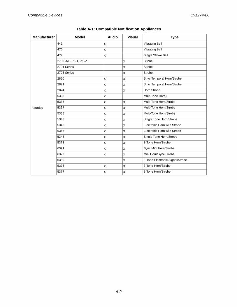
Compatible Devices 151274-L8
A-2
Faraday
446 x Vibrating Bell
476 x Vibrating Bell
477 x Single Stroke Bell
2700 -M. -R, -T, -Y, -Z x Strobe
2701 Series x Strobe
2705 Series x Strobe
2820 x x Snyc Temporal Horn/Strobe
2821 x x Snyc Temporal Horn/Strobe
2824 x x Horn Strobe
5333 x Multi-Tone Horn)
5336 x x Multi-Tone Horn/Strobe
5337 x x Multi-Tone Horn/Strobe
5338 x x Multi-Tone Horn/Strobe
5343 x x Single Tone Horn/Strobe
5346 x x Electronic Horn with Strobe
5347 x x Electronic Horn with Strobe
5348 x x Single Tone Horn/Strobe
5373 x x 8-Tone Horn/Strobe
6321 x x Sync Mini Horn/Strobe
6322 x x Mini Horn/Sync Strobe
6380 x 8-Tone Electronic Signal/Strobe
5376 x x 8-Tone Horn/Strobe
5377 x x 8-Tone Horn/Strobe
Table A-1: Compatible Notification Appliances
Manufacturer Model Audio Visual Type
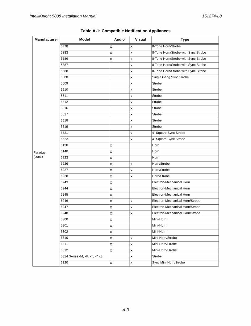
IntelliKnight 5808 Installation Manual 151274-L8
A-3
Faraday(cont.)
5378 x x 8-Tone Horn/Strobe
5383 x x 8-Tone Horn/Strobe with Sync Strobe
5386 x x 8-Tone Horn/Strobe with Sync Strobe
5387 x 8-Tone Horn/Strobe with Sync Strobe
5388 x 8-Tone Horn/Strobe with Sync Strobe
5508 x Single Gang Sync Strobe
5509 x Strobe
5510 x Strobe
5511 x Strobe
5512 x Strobe
5516 x Strobe
5517 x Strobe
5518 x Strobe
5519 x Strobe
5521 x 4” Square Sync Strobe
5522 x 4” Square Sync Strobe
6120 x Horn
6140 x Horn
6223 x Horn
6226 x x Horn/Strobe
6227 x x Horn/Strobe
6228 x x Horn/Strobe
6243 x Electron-Mechanical Horn
6244 x Electron-Mechanical Horn
6245 x Electron-Mechanical Horn
6246 x x Electron-Mechanical Horn/Strobe
6247 x x Electron-Mechanical Horn/Strobe
6248 x x Electron-Mechanical Horn/Strobe
6300 x Mini-Horn
6301 x Mini-Horn
6302 x Mini-Horn
6310 x x Mini-Horn/Strobe
6311 x x Mini-Horn/Strobe
6312 x x Mini-Horn/Strobe
6314 Series -M, -R, -T, -Y, -Z x Strobe
6320 x x Sync Mini Horn/Strobe
Table A-1: Compatible Notification Appliances
Manufacturer Model Audio Visual Type
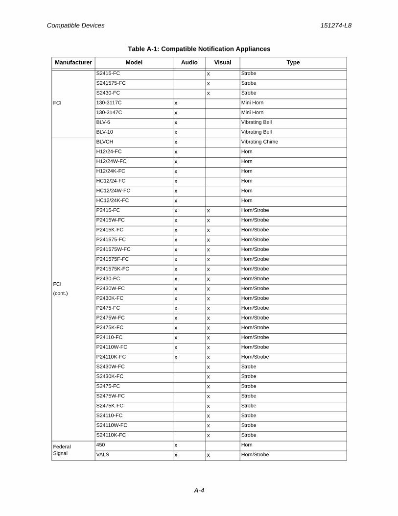
Compatible Devices 151274-L8
A-4
FCI
S2415-FC x Strobe
S241575-FC x Strobe
S2430-FC x Strobe
130-3117C x Mini Horn
130-3147C x Mini Horn
BLV-6 x Vibrating Bell
BLV-10 x Vibrating Bell
FCI
(cont.)
BLVCH x Vibrating Chime
H12/24-FC x Horn
H12/24W-FC x Horn
H12/24K-FC x Horn
HC12/24-FC x Horn
HC12/24W-FC x Horn
HC12/24K-FC x Horn
P2415-FC x x Horn/Strobe
P2415W-FC x x Horn/Strobe
P2415K-FC x x Horn/Strobe
P241575-FC x x Horn/Strobe
P241575W-FC x x Horn/Strobe
P241575F-FC x x Horn/Strobe
P241575K-FC x x Horn/Strobe
P2430-FC x x Horn/Strobe
P2430W-FC x x Horn/Strobe
P2430K-FC x x Horn/Strobe
P2475-FC x x Horn/Strobe
P2475W-FC x x Horn/Strobe
P2475K-FC x x Horn/Strobe
P24110-FC x x Horn/Strobe
P24110W-FC x x Horn/Strobe
P24110K-FC x x Horn/Strobe
S2430W-FC x Strobe
S2430K-FC x Strobe
S2475-FC x Strobe
S2475W-FC x Strobe
S2475K-FC x Strobe
S24110-FC x Strobe
S24110W-FC x Strobe
S24110K-FC x Strobe
Federal Signal
450 x Horn
VALS x x Horn/Strobe
Table A-1: Compatible Notification Appliances
Manufacturer Model Audio Visual Type

IntelliKnight 5808 Installation Manual 151274-L8
A-5
Gentex
GEC-24-15 x x Horn/Strobe
GEC-24-30 x x Horn/Strobe
GEC-24-60 x x Horn/Strobe
GEC-24-75 x x Horn/Strobe
GEC-24-177 x x Horn/Strobe
GEC-24-110 x x Horn/Strobe
GEC-24-15/75 x x Horn/Strobe
GX91 x MiniHorn Steady Tone
GX93 x MiniHorn Temporal Tone
Gentex
(cont.)
HG124 x Horn
HS24-15 x x Horn/Strobe
HS24-30 x x Horn/Strobe
HS24-60 x x Horn/Strobe
HS24-75 x x Horn/Strobe
HS24-110 x x Horn/Strobe
HS24-1575 x x Horn/Strobe
GCC24 x x Multi Candella Horn/Strobe Ceiling Mount
GCCR24 x Multi Candella Horn/Strobe Ceiling Mount
GCS24 x Multi Candella Strobe Ceiling Mount
GCSR24 x Multi Candella Strobe Ceiling Mount
GECR-24 x x Multi Candella Horn/Strobe
GES24-15 x Strobe
GES24-30 x Strobe
GES24-60 x Strobe
GES24-75 x Strobe
GES24-110 x Strobe
GES24-15/75 x Strobe
GES24-177 x Strobe
GES3-24 x Multi Candella Strobe
GESR-24 x Multi Candella Strobe
GEH-24 x Horn
ST24-30 x Strobe
ST24-60 x Strobe
ST24-75 x Strobe
ST24-110 x Strobe
ST24-1575 x Strobe
WGEC24-75W x x Weatherproof Horn/Strobe
WGES24-75W x Weatherproof Strobe
WGMS-24-X x x Horn/Strobe
Table A-1: Compatible Notification Appliances
Manufacturer Model Audio Visual Type
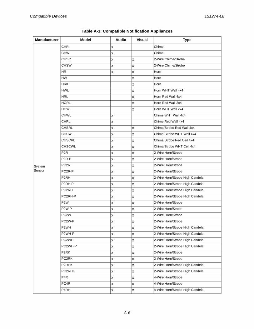
Compatible Devices 151274-L8
A-6
System Sensor
CHR x Chime
CHW x Chime
CHSR x x 2-Wire Chime/Strobe
CHSW x x 2-Wire Chime/Strobe
HR x x Horn
HW x Horn
HRK x Horn
HWL x Horn WHT Wall 4x4
HRL x Horn Red Wall 4x4
HGRL x Horn Red Wall 2x4
HGWL x Horn WHT Wall 2x4
CHWL x Chime WHT Wall 4x4
CHRL x Chime Red Wall 4x4
CHSRL x x Chime/Strobe Red Wall 4x4
CHSWL x x Chime/Strobe WHT Wall 4x4
CHSCRL x x Chime/Strobe Red Ceil 4x4
CHSCWL x x Chime/Strobe WHT Ceil 4x4
P2R x x 2-Wire Horn/Strobe
P2R-P x x 2-Wire Horn/Strobe
PC2R x x 2-Wire Horn/Strobe
PC2R-P x x 2-Wire Horn/Strobe
P2RH x x 2-Wire Horn/Strobe High Candela
P2RH-P x x 2-Wire Horn/Strobe High Candela
PC2RH x x 2-Wire Horn/Strobe High Candela
PC2RH-P x x 2-Wire Horn/Strobe High Candela
P2W x x 2-Wire Horn/Strobe
P2W-P x x 2-Wire Horn/Strobe
PC2W x x 2-Wire Horn/Strobe
PC2W-P x x 2-Wire Horn/Strobe
P2WH x x 2-Wire Horn/Strobe High Candela
P2WH-P x x 2-Wire Horn/Strobe High Candela
PC2WH x x 2-Wire Horn/Strobe High Candela
PC2WH-P x x 2-Wire Horn/Strobe High Candela
P2RK x x 2-Wire Horn/Strobe
PC2RK x x 2-Wire Horn/Strobe
P2RHK x x 2-Wire Horn/Strobe High Candela
PC2RHK x x 2-Wire Horn/Strobe High Candela
P4R x x 4-Wire Horn/Strobe
PC4R x x 4-Wire Horn/Strobe
P4RH x x 4-Wire Horn/Strobe High Candela
Table A-1: Compatible Notification Appliances
Manufacturer Model Audio Visual Type
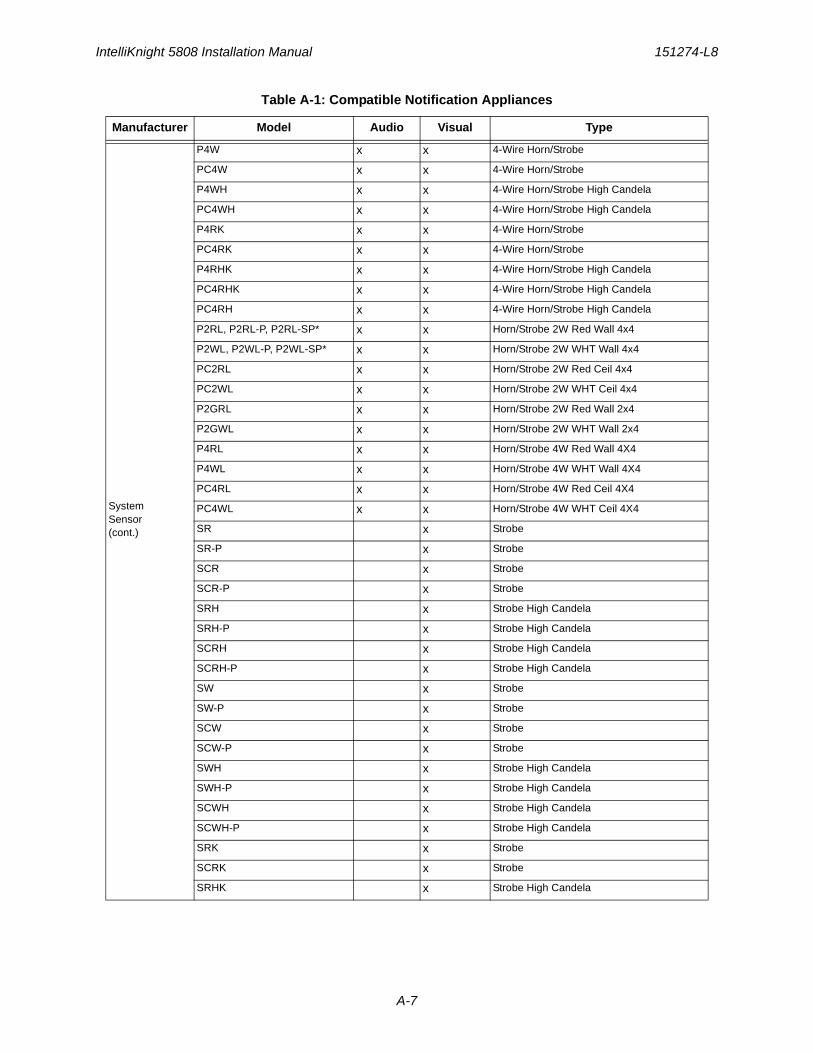
IntelliKnight 5808 Installation Manual 151274-L8
A-7
System Sensor(cont.)
P4W x x 4-Wire Horn/Strobe
PC4W x x 4-Wire Horn/Strobe
P4WH x x 4-Wire Horn/Strobe High Candela
PC4WH x x 4-Wire Horn/Strobe High Candela
P4RK x x 4-Wire Horn/Strobe
PC4RK x x 4-Wire Horn/Strobe
P4RHK x x 4-Wire Horn/Strobe High Candela
PC4RHK x x 4-Wire Horn/Strobe High Candela
PC4RH x x 4-Wire Horn/Strobe High Candela
P2RL, P2RL-P, P2RL-SP* x x Horn/Strobe 2W Red Wall 4x4
P2WL, P2WL-P, P2WL-SP* x x Horn/Strobe 2W WHT Wall 4x4
PC2RL x x Horn/Strobe 2W Red Ceil 4x4
PC2WL x x Horn/Strobe 2W WHT Ceil 4x4
P2GRL x x Horn/Strobe 2W Red Wall 2x4
P2GWL x x Horn/Strobe 2W WHT Wall 2x4
P4RL x x Horn/Strobe 4W Red Wall 4X4
P4WL x x Horn/Strobe 4W WHT Wall 4X4
PC4RL x x Horn/Strobe 4W Red Ceil 4X4
PC4WL x x Horn/Strobe 4W WHT Ceil 4X4
SR x Strobe
SR-P x Strobe
SCR x Strobe
SCR-P x Strobe
SRH x Strobe High Candela
SRH-P x Strobe High Candela
SCRH x Strobe High Candela
SCRH-P x Strobe High Candela
SW x Strobe
SW-P x Strobe
SCW x Strobe
SCW-P x Strobe
SWH x Strobe High Candela
SWH-P x Strobe High Candela
SCWH x Strobe High Candela
SCWH-P x Strobe High Candela
SRK x Strobe
SCRK x Strobe
SRHK x Strobe High Candela
Table A-1: Compatible Notification Appliances
Manufacturer Model Audio Visual Type
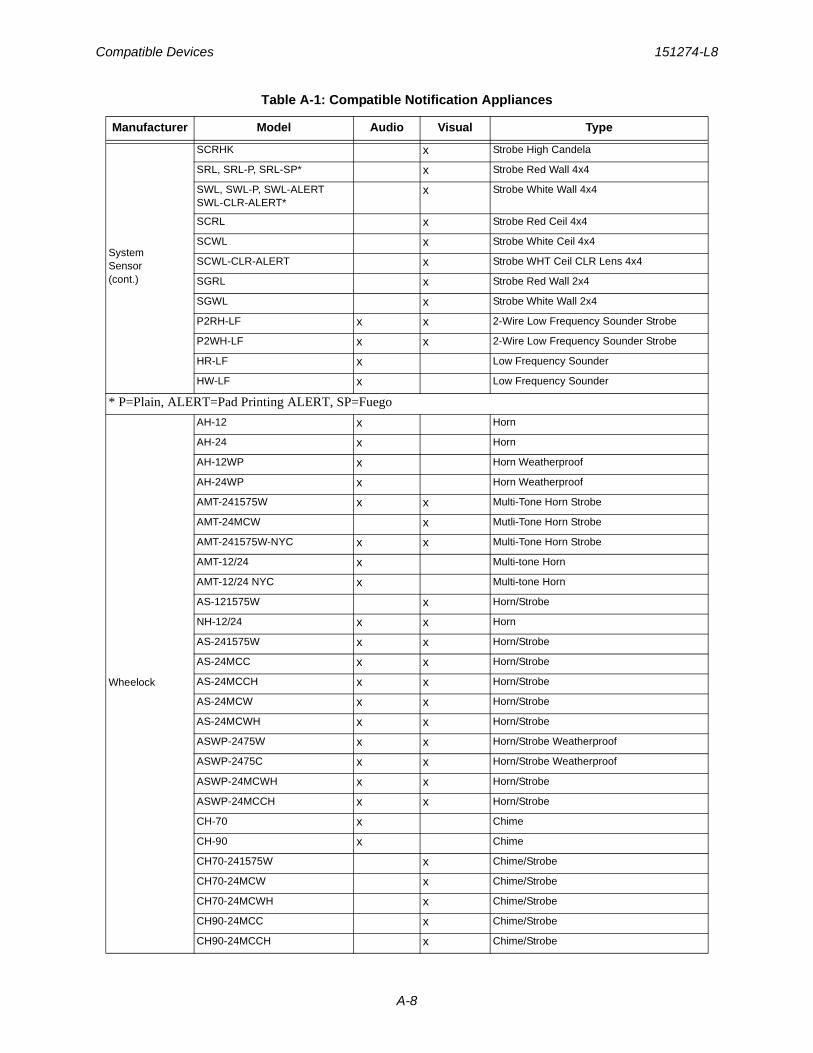
Compatible Devices 151274-L8
A-8
System Sensor(cont.)
SCRHK x Strobe High Candela
SRL, SRL-P, SRL-SP* x Strobe Red Wall 4x4
SWL, SWL-P, SWL-ALERTSWL-CLR-ALERT*
x Strobe White Wall 4x4
SCRL x Strobe Red Ceil 4x4
SCWL x Strobe White Ceil 4x4
SCWL-CLR-ALERT x Strobe WHT Ceil CLR Lens 4x4
SGRL x Strobe Red Wall 2x4
SGWL x Strobe White Wall 2x4
P2RH-LF x x 2-Wire Low Frequency Sounder Strobe
P2WH-LF x x 2-Wire Low Frequency Sounder Strobe
HR-LF x Low Frequency Sounder
HW-LF x Low Frequency Sounder
* P=Plain, ALERT=Pad Printing ALERT, SP=Fuego
Wheelock
AH-12 x Horn
AH-24 x Horn
AH-12WP x Horn Weatherproof
AH-24WP x Horn Weatherproof
AMT-241575W x x Multi-Tone Horn Strobe
AMT-24MCW x Mutli-Tone Horn Strobe
AMT-241575W-NYC x x Multi-Tone Horn Strobe
AMT-12/24 x Multi-tone Horn
AMT-12/24 NYC x Multi-tone Horn
AS-121575W x Horn/Strobe
NH-12/24 x x Horn
AS-241575W x x Horn/Strobe
AS-24MCC x x Horn/Strobe
AS-24MCCH x x Horn/Strobe
AS-24MCW x x Horn/Strobe
AS-24MCWH x x Horn/Strobe
ASWP-2475W x x Horn/Strobe Weatherproof
ASWP-2475C x x Horn/Strobe Weatherproof
ASWP-24MCWH x x Horn/Strobe
ASWP-24MCCH x x Horn/Strobe
CH-70 x Chime
CH-90 x Chime
CH70-241575W x Chime/Strobe
CH70-24MCW x Chime/Strobe
CH70-24MCWH x Chime/Strobe
CH90-24MCC x Chime/Strobe
CH90-24MCCH x Chime/Strobe
Table A-1: Compatible Notification Appliances
Manufacturer Model Audio Visual Type
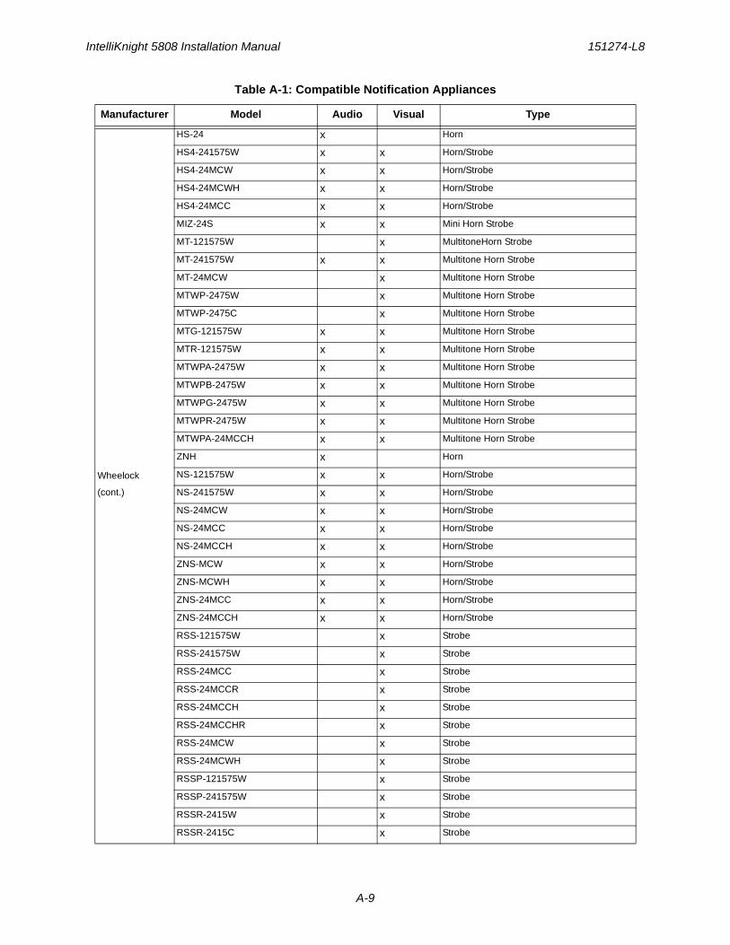
IntelliKnight 5808 Installation Manual 151274-L8
A-9
Wheelock
(cont.)
HS-24 x Horn
HS4-241575W x x Horn/Strobe
HS4-24MCW x x Horn/Strobe
HS4-24MCWH x x Horn/Strobe
HS4-24MCC x x Horn/Strobe
MIZ-24S x x Mini Horn Strobe
MT-121575W x MultitoneHorn Strobe
MT-241575W x x Multitone Horn Strobe
MT-24MCW x Multitone Horn Strobe
MTWP-2475W x Multitone Horn Strobe
MTWP-2475C x Multitone Horn Strobe
MTG-121575W x x Multitone Horn Strobe
MTR-121575W x x Multitone Horn Strobe
MTWPA-2475W x x Multitone Horn Strobe
MTWPB-2475W x x Multitone Horn Strobe
MTWPG-2475W x x Multitone Horn Strobe
MTWPR-2475W x x Multitone Horn Strobe
MTWPA-24MCCH x x Multitone Horn Strobe
ZNH x Horn
NS-121575W x x Horn/Strobe
NS-241575W x x Horn/Strobe
NS-24MCW x x Horn/Strobe
NS-24MCC x x Horn/Strobe
NS-24MCCH x x Horn/Strobe
ZNS-MCW x x Horn/Strobe
ZNS-MCWH x x Horn/Strobe
ZNS-24MCC x x Horn/Strobe
ZNS-24MCCH x x Horn/Strobe
RSS-121575W x Strobe
RSS-241575W x Strobe
RSS-24MCC x Strobe
RSS-24MCCR x Strobe
RSS-24MCCH x Strobe
RSS-24MCCHR x Strobe
RSS-24MCW x Strobe
RSS-24MCWH x Strobe
RSSP-121575W x Strobe
RSSP-241575W x Strobe
RSSR-2415W x Strobe
RSSR-2415C x Strobe
Table A-1: Compatible Notification Appliances
Manufacturer Model Audio Visual Type
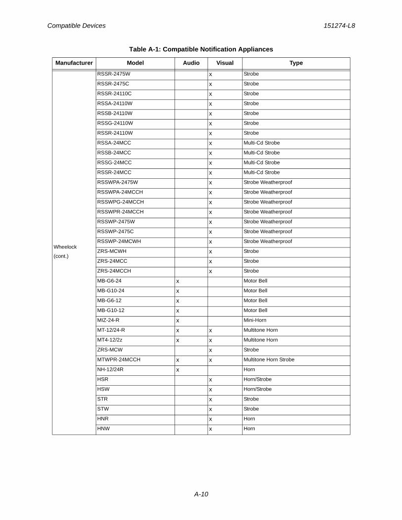
Compatible Devices 151274-L8
A-10
Wheelock
(cont.)
RSSR-2475W x Strobe
RSSR-2475C x Strobe
RSSR-24110C x Strobe
RSSA-24110W x Strobe
RSSB-24110W x Strobe
RSSG-24110W x Strobe
RSSR-24110W x Strobe
RSSA-24MCC x Multi-Cd Strobe
RSSB-24MCC x Multi-Cd Strobe
RSSG-24MCC x Multi-Cd Strobe
RSSR-24MCC x Multi-Cd Strobe
RSSWPA-2475W x Strobe Weatherproof
RSSWPA-24MCCH x Strobe Weatherproof
RSSWPG-24MCCH x Strobe Weatherproof
RSSWPR-24MCCH x Strobe Weatherproof
RSSWP-2475W x Strobe Weatherproof
RSSWP-2475C x Strobe Weatherproof
RSSWP-24MCWH x Strobe Weatherproof
ZRS-MCWH x Strobe
ZRS-24MCC x Strobe
ZRS-24MCCH x Strobe
MB-G6-24 x Motor Bell
MB-G10-24 x Motor Bell
MB-G6-12 x Motor Bell
MB-G10-12 x Motor Bell
MIZ-24-R x Mini-Horn
MT-12/24-R x x Multitone Horn
MT4-12/2z x x Multitone Horn
ZRS-MCW x Strobe
MTWPR-24MCCH x x Multitone Horn Strobe
NH-12/24R x Horn
HSR x Horn/Strobe
HSW x Horn/Strobe
STR x Strobe
STW x Strobe
HNR x Horn
HNW x Horn
Table A-1: Compatible Notification Appliances
Manufacturer Model Audio Visual Type
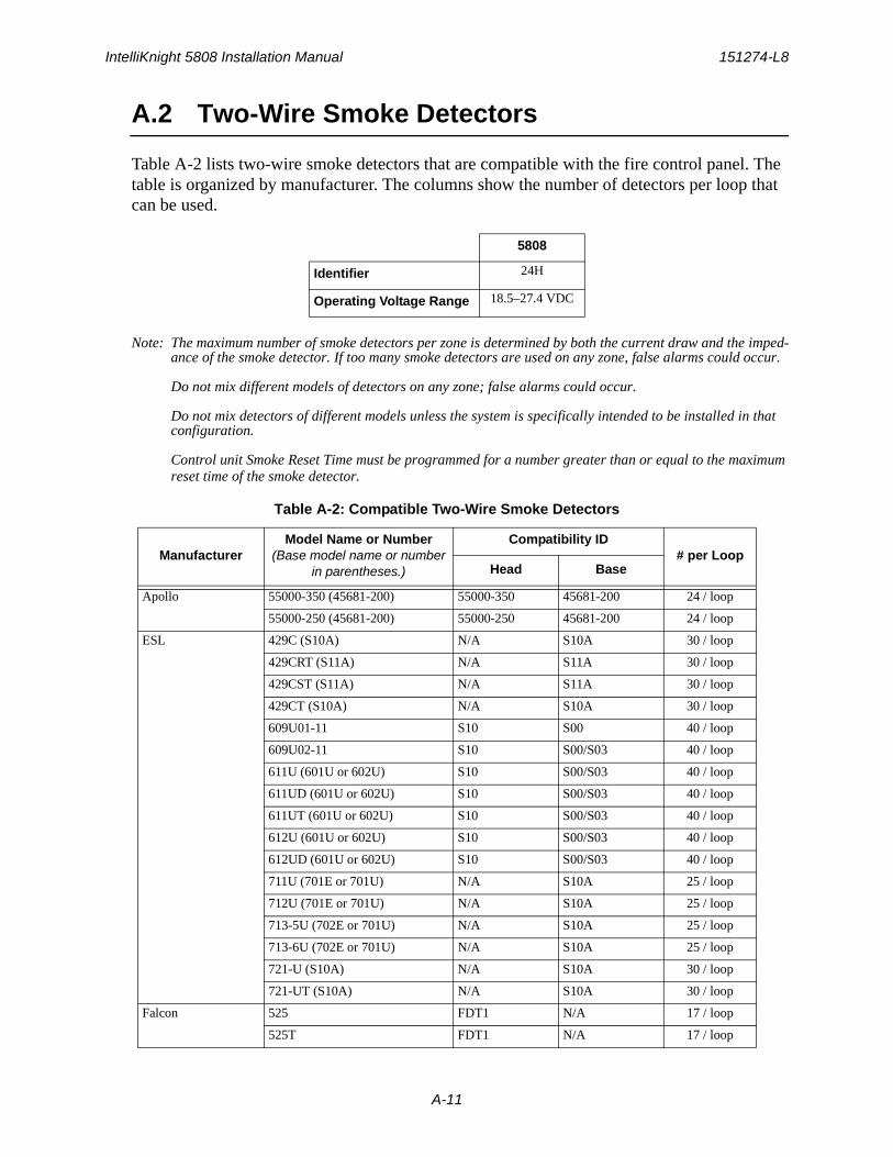
IntelliKnight 5808 Installation Manual 151274-L8
A-11
A.2 Two-Wire Smoke Detectors
Table A-2 lists two-wire smoke detectors that are compatible with the fire control panel. The table is organized by manufacturer. The columns show the number of detectors per loop that can be used.
Note: The maximum number of smoke detectors per zone is determined by both the current draw and the imped-ance of the smoke detector. If too many smoke detectors are used on any zone, false alarms could occur.
Do not mix different models of detectors on any zone; false alarms could occur.
Do not mix detectors of different models unless the system is specifically intended to be installed in that configuration.
Control unit Smoke Reset Time must be programmed for a number greater than or equal to the maximum reset time of the smoke detector.
5808
Identifier 24H
Operating Voltage Range 18.5–27.4 VDC
Table A-2: Compatible Two-Wire Smoke Detectors
ManufacturerModel Name or Number
(Base model name or number in parentheses.)
Compatibility ID# per Loop
Head Base
Apollo 55000-350 (45681-200) 55000-350 45681-200 24 / loop
55000-250 (45681-200) 55000-250 45681-200 24 / loop
ESL 429C (S10A) N/A S10A 30 / loop
429CRT (S11A) N/A S11A 30 / loop
429CST (S11A) N/A S11A 30 / loop
429CT (S10A) N/A S10A 30 / loop
609U01-11 S10 S00 40 / loop
609U02-11 S10 S00/S03 40 / loop
611U (601U or 602U) S10 S00/S03 40 / loop
611UD (601U or 602U) S10 S00/S03 40 / loop
611UT (601U or 602U) S10 S00/S03 40 / loop
612U (601U or 602U) S10 S00/S03 40 / loop
612UD (601U or 602U) S10 S00/S03 40 / loop
711U (701E or 701U) N/A S10A 25 / loop
712U (701E or 701U) N/A S10A 25 / loop
713-5U (702E or 701U) N/A S10A 25 / loop
713-6U (702E or 701U) N/A S10A 25 / loop
721-U (S10A) N/A S10A 30 / loop
721-UT (S10A) N/A S10A 30 / loop
Falcon 525 FDT1 N/A 17 / loop
525T FDT1 N/A 17 / loop
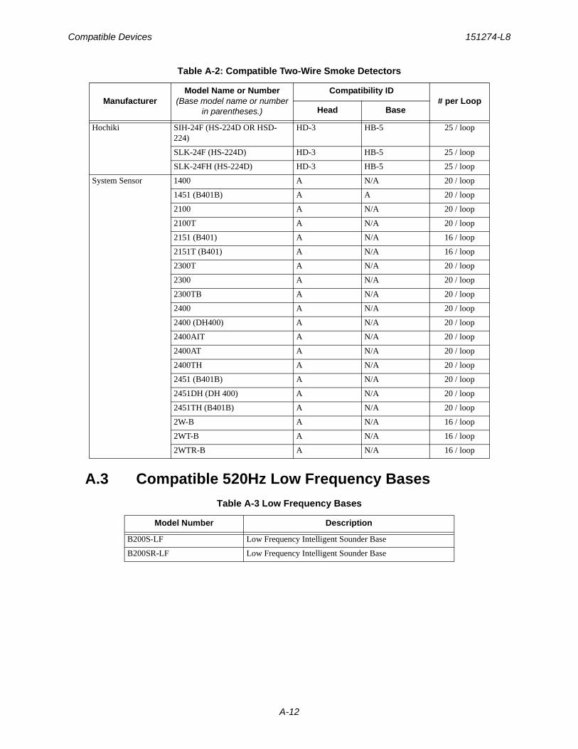
Compatible Devices 151274-L8
A-12
A.3 Compatible 520Hz Low Frequency Bases
Hochiki SIH-24F (HS-224D OR HSD-224)
HD-3 HB-5 25 / loop
SLK-24F (HS-224D) HD-3 HB-5 25 / loop
SLK-24FH (HS-224D) HD-3 HB-5 25 / loop
System Sensor 1400 A N/A 20 / loop
1451 (B401B) A A 20 / loop
2100 A N/A 20 / loop
2100T A N/A 20 / loop
2151 (B401) A N/A 16 / loop
2151T (B401) A N/A 16 / loop
2300T A N/A 20 / loop
2300 A N/A 20 / loop
2300TB A N/A 20 / loop
2400 A N/A 20 / loop
2400 (DH400) A N/A 20 / loop
2400AIT A N/A 20 / loop
2400AT A N/A 20 / loop
2400TH A N/A 20 / loop
2451 (B401B) A N/A 20 / loop
2451DH (DH 400) A N/A 20 / loop
2451TH (B401B) A N/A 20 / loop
2W-B A N/A 16 / loop
2WT-B A N/A 16 / loop
2WTR-B A N/A 16 / loop
Table A-3 Low Frequency Bases
Model Number Description
B200S-LF Low Frequency Intelligent Sounder Base
B200SR-LF Low Frequency Intelligent Sounder Base
Table A-2: Compatible Two-Wire Smoke Detectors
ManufacturerModel Name or Number
(Base model name or number in parentheses.)
Compatibility ID# per Loop
Head Base

151274-L8
B-1
Appendix BSpecial Characters Lists
This section contains tables of programmable characters that may be used for device, module, and zone names or phone numbers.
B.1 Characters used for Naming
Table B-1 list the available character and their associated numeric designator. When programming these numbers can be entered as a short cut to using the up or down arrow keys, to select characters when naming a point or zone.
Table B-1: Character Table
000 A 001 B 002 C 003 D
004 E 005 F 006 G 007 H
008 I 009 J 010 K 011 L
012 M 013 N 014 O 015 P
016 Q 017 R 018 S 019 T
020 U 021 V 022 W 023 X
024 Y 025 Z 026 a 027 b
028 c 029 d 030 e 031 f
032 g 033 h 034 i 035 j
036 k 037 l 038 m 039 n
040 o 041 p 042 q 043 r
044 s 045 t 046 u 047 v
048 w 049 x 050 y 051 z
052 053 0 054 1 055 2
056 3 057 4 058 5 059 6
060 7 061 8 062 9 063 :
064 - 065 _ 066 . 067 ,
068 & 069 * 070 #

Honeywell Fire Product Warranty and Return Policy
General Terms and Conditions• All new fire products manufactured by Honeywell Silent Knight have a limited warranty period of 36
months from the date of manufacture against defects in materials and workmanship. See limited warranty statement for details.
• This limited warranty does not apply to those products that are damaged due to misuse, abuse, negligence, exposure to adverse environmental conditions, or have been modified in any manner whatsoever.
Repair and RMA Procedure• All products that are returned to Honeywell for credit or repair require a RMA (Return Authorization)
number. Call Customer Service at 800-328-0103 or 203-484-7161 between 8:00 A.M. and 5:00 P.M. EST, Monday through Friday to obtain a return authorization number.
• Honeywell Silent Knight and Farenhyt Series Technical Support is available at 800-446-6444 between 8:00 A.M. and 5:00 P.M. CST, Monday through Friday.
• All returns for credit are subject to inspection and testing at the factory before actual determination is made to allow credit.
• RMA number must be prominently displayed on the outside of the shipping box. See return address example under Advanced Replacement Policy.
• Included with each return should be: a packing slip that has the RMA number, a content list, and a detailed description of the problem.
• All products returned by Honeywell must be sent freight pre-paid. After the product is processed, Honeywell will pay for shipping product back to customer via UPS ground.
• Return the Honeywell Silent Knight product circuit board only. Products that are returned in cabinets will be charged an additional $50 to cover the extra shipping and handling costs over board only returns. Do not return batteries. Honeywell has the authority to determine if a product is repairable. Products that are deemed un-repairable will be returned to the customer.
• Product that is returned that has a board date code more than 36 months from date of manufacture will be repaired and the customer will be assessed the standard Honeywell Silent Knight repair charge for that model.
Advanced Replacement Policy• Honeywell Silent Knight and Farenhyt Series offers an option of advance replacement for fire product
printed circuit boards that fail during the first 6 months of the warranty period. These items must be returned with transportation charges prepaid and must be accompanied by a return authorization.
• For advance replacement of a defective board, contact your local Honeywell Silent Knight distributor or call Honeywell Silent Knight at 800-328-0103 to obtain a RMA (Return Authorization) number and request advanced replacement.
• A new or refurbished board will be shipped to the customer. The customer will initially be billed for the replacement board but a credit will be issued after the repairable board is received at Honeywell Silent Knight. All returned products must comply with the guidelines described under “General Terms and Conditions” and “Repair and RMA Procedure”.
• The defective board must be returned within 30 days of shipment of replacement board for customer to receive credit. No credit will be issued if the returned board was damaged due to misuse or abuse.

• Repairs and returns should be sent to:Honeywell Fire SystemsAttn: Repair Department / RA Number_______________________12 Clintonville RoadNorthford, CT 06472 USA
Manufacturer Warranties and Limitation of Liability
Manufacturer Warranties. Subject to the limitations set forth herein, Manufacturer warrants that the Products manufactured by it in its Northford, Connecticut facility and sold by it to its authorized Distributors shall be free, under normal use and service, from defects in material and workmanship for a period of thirty six months (36) months from the date of manufacture (effective Jan. 1, 2009). The Products manufactured and sold by Manufacturer are date stamped at the time of production. Manufacturer does not warrant Products that are not manufactured by it in its Northford, Connecticut facility but assigns to its Distributor, to extent possible, any warranty offered by the manufacturer of such product. This warranty shall be void if a Product is altered, service repaired by anyone other than Manufacturer or its authorized Distributors. This warranty shall also be void if there is a failure to maintain the Products and the systems in which they operate in proper working conditions.
MANUFACTURER MAKES NO FURTHER WARRANTIES, AND DISCLAIMS ANY AND ALL OTHER WARRANTIES, EITHER EXPRESSED OR IMPLIED, WITH RESPECT TO THE PRODUCTS,TRADEMARKS, PROGRAMS AND SERVICES RENDERED BY MANUFACTURER INCLUDING WITHOUT LIMITATION, INFRINGEMENT, TITLE, MERCHANTABILITY, OR FITNESS FOR ANY PARTICULAR PURPOSE. MANUFACTURER SHALL NOT BE LIABLE FOR ANY PERSONAL INJURY OR DEATH WHICH MAY ARISE IN THE COURSE OF, OR AS A RESULT OF, PERSONAL, COMMERCIAL OR INDUSTRIAL USES OF ITS PRODUCTS.
This document constitutes the only warranty made by Manufacturer with respect to its products and replaces all previous warranties and is the only warranty made by Manufacturer. No increase or alteration, written or verbal, of the obligation of this warranty is authorized. Manufacturer does not represent that its products will prevent any loss by fire or otherwise.
Warranty Claims. Manufacturer shall replace or repair, at Manufacturer's discretion, each part returned by its authorized Distributor and acknowledged by Manufacturer to be defective, provided that such part shall have been returned to Manufacturer with all charges prepaid and the authorized Distributor has completed Manufacturer's Return Material Authorization form. The replacement part shall come from Manufacturer's stock and may be new or refurbished. THE FOREGOING IS DISTRIBUTOR'S SOLE AND EXCLUSIVE REMEDY IN THE EVENT OF A WARRANTY CLAIM.
Warn-HL-08-2009.fm
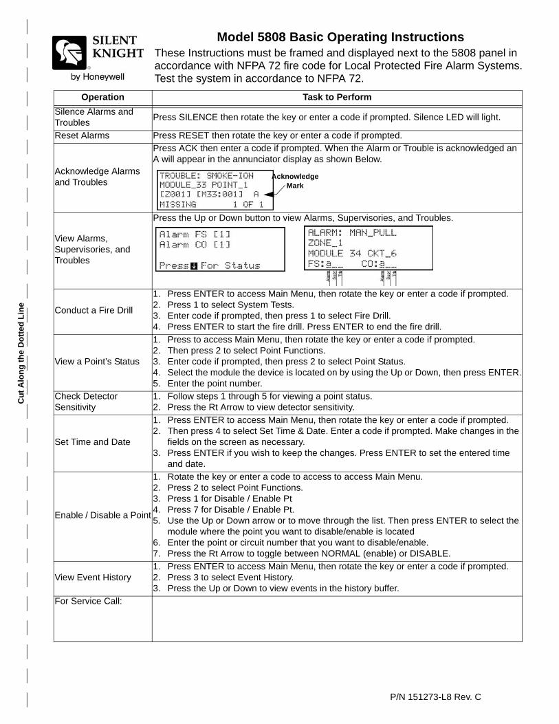
Cu
t A
lon
g t
he
Do
tted
Lin
e
P/N 151273-L8 Rev. C
Model 5808 Basic Operating InstructionsThese Instructions must be framed and displayed next to the 5808 panel in accordance with NFPA 72 fire code for Local Protected Fire Alarm Systems. Test the system in accordance to NFPA 72.
Operation Task to Perform
Silence Alarms and Troubles
Press SILENCE then rotate the key or enter a code if prompted. Silence LED will light.
Reset Alarms Press RESET then rotate the key or enter a code if prompted.
Acknowledge Alarms and Troubles
Press ACK then enter a code if prompted. When the Alarm or Trouble is acknowledged an A will appear in the annunciator display as shown Below.
View Alarms, Supervisories, and Troubles
Press the Up or Down button to view Alarms, Supervisories, and Troubles.
Conduct a Fire Drill
1. Press ENTER to access Main Menu, then rotate the key or enter a code if prompted.2. Press 1 to select System Tests.3. Enter code if prompted, then press 1 to select Fire Drill.4. Press ENTER to start the fire drill. Press ENTER to end the fire drill.
View a Point’s Status
1. Press to access Main Menu, then rotate the key or enter a code if prompted.2. Then press 2 to select Point Functions.3. Enter code if prompted, then press 2 to select Point Status.4. Select the module the device is located on by using the Up or Down, then press ENTER.5. Enter the point number.
Check Detector Sensitivity
1. Follow steps 1 through 5 for viewing a point status.2. Press the Rt Arrow to view detector sensitivity.
Set Time and Date
1. Press ENTER to access Main Menu, then rotate the key or enter a code if prompted.2. Then press 4 to select Set Time & Date. Enter a code if prompted. Make changes in the
fields on the screen as necessary.3. Press ENTER if you wish to keep the changes. Press ENTER to set the entered time
and date.
Enable / Disable a Point
1. Rotate the key or enter a code to access to access Main Menu.2. Press 2 to select Point Functions.3. Press 1 for Disable / Enable Pt4. Press 7 for Disable / Enable Pt.5. Use the Up or Down arrow or to move through the list. Then press ENTER to select the
module where the point you want to disable/enable is located6. Enter the point or circuit number that you want to disable/enable.7. Press the Rt Arrow to toggle between NORMAL (enable) or DISABLE.
View Event History1. Press ENTER to access Main Menu, then rotate the key or enter a code if prompted.2. Press 3 to select Event History.3. Press the Up or Down to view events in the history buffer.
For Service Call:
AcknowledgeMark

Cu
t A
lon
g t
he
Do
tted
Lin
e


Silent Knight12 Clintonville Road
Northford, CT 06472-1610203-484-7161
Fax: 203-484-7118
www.silentknight.com