Embed Size (px)
Citation preview
INTELLIGENT TRANSPORTATION SYSTEMS
TELECOMMUNICATIONS STRATEGY
Infrastructure Affairs
Roads Design Department
Version 1.0
December 2014
ITS Telecommunications Strategy
Hard copies of this document are uncontrolled
Page i
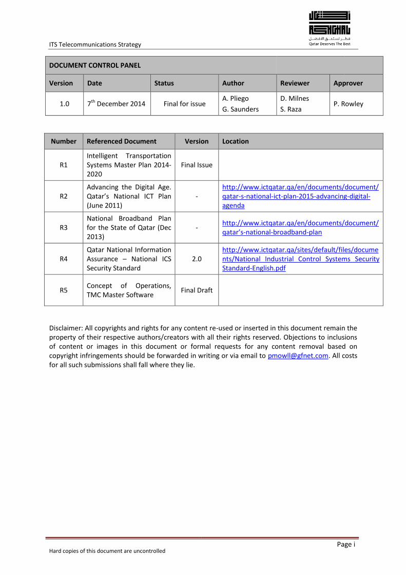
DOCUMENT CONTROL PANEL
Version Date Status Author Reviewer Approver
1.0 7th December 2014 Final for issue A. Pliego
G. Saunders
D. Milnes
S. Raza P. Rowley
Number Referenced Document Version Location
R1 Intelligent Transportation Systems Master Plan 2014-2020
Final Issue
R2 Advancing the Digital Age. Qatar’s National ICT Plan (June 2011)
- http://www.ictqatar.qa/en/documents/document/qatar-s-national-ict-plan-2015-advancing-digital-agenda
R3 National Broadband Plan for the State of Qatar (Dec 2013)
- http://www.ictqatar.qa/en/documents/document/qatar’s-national-broadband-plan
R4 Qatar National Information Assurance – National ICS Security Standard
2.0 http://www.ictqatar.qa/sites/default/files/documents/National Industrial Control Systems Security Standard-English.pdf
R5 Concept of Operations, TMC Master Software
Final Draft
Disclaimer: All copyrights and rights for any content re-used or inserted in this document remain the property of their respective authors/creators with all their rights reserved. Objections to inclusions of content or images in this document or formal requests for any content removal based on copyright infringements should be forwarded in writing or via email to [email protected]. All costs for all such submissions shall fall where they lie.
ITS Telecommunications Strategy
Hard copies of this document are uncontrolled
Page ii
Glossary of acronyms
Term Definition
3G Third Generation Mobile telephony and data
4G Fourth Generation Mobile telephony and data
AA Ashghal Asset Affairs
AN Access Node
BPF Business Process Framework
CCTV Closed Circuit Television
ConOps Concept of Operations
COTS Commercial Off The Shelf
C2C Centre to Centre
C2F Centre to Field
CWDM Coarse Wave Division Multiplexing
CRA Communications Regulatory Authority
DIA Doha International Airport
DN Distribution Node
DSRC Dedicated Short Range Communications
DWDM Dense Wave Division Multiplexing
EBSD Ashghal Engineering Business Support Department
EXW Expressway
F2C Field to Centre
GbE Gigabit Ethernet
GEC General Engineering Consultant
GIS Geographic Information System
GME Ground Mounted Enclosure
GPRS General Packet Radio System
GPS Global Positioning System
GSM Global System for Mobile
HCB Human Capacity Building
HIA Hamad International Airport
ICS Industrial Control Systems
IEEE Institute of Electrical and Electronics Engineers
IP Internet Protocol
ISD Ashghal Information Systems Department
IA Ashghal Infrastructure Affairs
IP Internet Protocol
ITS Intelligent Transportation Systems
ITU-R International Telecommunications Union (Radio sector)
ITU-T International Telecommunications Union (Telecoms sector)
ITS Telecommunications Strategy
Hard copies of this document are uncontrolled
Page iii
LAN Local Area Network
LTE Long Term Evolution (4G)
LR&D Local Roads and Drainage
Mbps Megabits Per Second
MMUP Ministry of Municipality and Urban Planning
MOE Ministry of Environment
MOI Ministry of Interior
MPLS Multi Protocol Label Switching
MSTP Multiple Spanning Tree Protocol
NCC National Command Centre
NTCIP National Transportation Communications for ITS Protocol
NTMC National Transportation Management Centre
OAM Operations, Administration and Management
PC-WAN Principal Telecommunications Wide Area Network
PMC Programme Management Consultant
PTZ Pan-Tilt-Zoom (functions of CCTV)
PWA Public Works Authority (Ashghal)
QNBN Qatar National Broadband Network
QoS Quality of service
QR Qatar Rail
RNMC Road Network Management Centre
RSTP Rapid Spanning Tree Protocol
SCADA Supervisory Control And Data Acquisition
SCH Supreme Council for Health
SLA Service Level Agreement
STP Spanning Tree Protocol
SOP Standard Operating Procedure
TCP Transmission Control Protocol
TETRA Terrestrial Trunked Radio
TMC Transportation Management Centre
TSCR Traffic Signal Control Room
UMTS Universal Mobile Telecommunications System (3G)
VLAN Virtual LAN
WAN Wide Area Network
WDM Wave Division Multiplexing
WiMAX Worldwide Interoperability for Microwave Access
WLAN Wireless Local Area Network
ITS Telecommunications Strategy
Hard copies of this document are uncontrolled
Page iv
Table of Contents
Executive Summary ...................................................................................................................... 1
1 Introduction ......................................................................................................................... 4
2 Requirement for an ITS Telecommunications Strategy ........................................................... 5
2.1 Purpose of the Telecommunications Deployment Plan ......................................................... 5
3 Key Drivers and Enablers ...................................................................................................... 7
3.1 The Qatar National Vision 2030 .............................................................................................. 7
3.2 The Vision for ITS .................................................................................................................... 8
3.3 Roles and Responsibilities ....................................................................................................... 8
3.4 Stakeholders ........................................................................................................................... 9
4 Telecommunications policies .............................................................................................. 10
4.1 Telecommunications Regulation in Qatar ............................................................................ 10
4.2 Radio Spectrum for ITS and Automotive applications .......................................................... 10
4.3 Network Security .................................................................................................................. 12
5 The ITS Telecommunications Network ................................................................................. 13
5.1 Overview ............................................................................................................................... 13
5.2 Model and architecture for the ITS Telecommunications Network ..................................... 14
5.3 Topology of the ITS Telecommunications Network .............................................................. 17
5.4 Deployment considerations (constructability) ..................................................................... 18
5.5 Network availability .............................................................................................................. 21
5.6 Proposed Business Process Framework ................................................................................ 22
5.7 Alternatives for Operations, Administration and Maintenance ........................................... 24
6 Data Centres....................................................................................................................... 26
6.1 Introduction .......................................................................................................................... 26
6.2 Options .................................................................................................................................. 26
7 Key Challenges and Inhibitors ............................................................................................. 28
7.1 Providing a Future Proof network ......................................................................................... 28
7.2 Operations ............................................................................................................................ 28
7.3 Resources and skills .............................................................................................................. 28
8 Budgetary Estimates ........................................................................................................... 30
9 Outcomes and Benefits ....................................................................................................... 33
10 Next Steps ...................................................................................................................... 34
Appendix A. Products and services ............................................................................................. 36
A.1 Telecommunications for ITS ....................................................................................................... 36
A.2 Service packages ......................................................................................................................... 36
A.3 ITS Telecommunications domains .............................................................................................. 37
ITS Telecommunications Strategy
Hard copies of this document are uncontrolled
Page v
A.4 E-Commerce and e-government ................................................................................................ 38
A.5 Mobile data applications ............................................................................................................ 38
A.6 Connectivity, Control Centres and Data Centres ........................................................................ 39
A.7 Ashghal Corporate IT network .................................................................................................... 39
A.8 Network Security ........................................................................................................................ 39
Appendix B. Implementation, monitoring and evaluation ........................................................... 41
B.1 Infrastructure and build model ................................................................................................... 41
B.2 Delivery Timeline ........................................................................................................................ 41
B.3 Asset Sharing ............................................................................................................................... 42
B.4 Monitoring and Evaluation ......................................................................................................... 43
Appendix C. Technology and definitions ..................................................................................... 44
Appendix D. Drawings for the ITS telecommunications Network ................................................. 53
Figures
Figure 1 Relationship of the Telecommunications Strategy with ITS delivery ....................................... 4 Figure 2 Enablers ..................................................................................................................................... 7 Figure 3 Wireless based services and applications ............................................................................... 11 Figure 4 The overall ITS Telecommunications Network ....................................................................... 14 Figure 5 Hierarchical model for the ITS Telecommunications Network ............................................... 15 Figure 6 Example of cable routing ........................................................................................................ 21 Figure 7 Business Process Framework .................................................................................................. 23 Figure 8 ITS Telecommunications Network capital expenditure estimate ........................................... 31 Figure 9 RACI Matrix ............................................................................................................................. 35 Figure 10 Logical association of ITS components ................................................................................. 37 Figure 11 Proposed routing for Centre to Centre communications ..................................................... 54 Figure 12 High level topology for the ITS telecommunications Network ............................................. 55 Figure 13 Fibre pathing for for ITS LAN and PC WAN (Expressway schemes) ...................................... 56 Figure 14 Fibre schematic for ITS LAN and PC WAN (Expressway schemes) ........................................ 57 Figure 15 Fibre pathing for for ITS LAN and PC WAN (Local Roads schemes) ...................................... 58 Figure 16 Fibre schematic for for ITS LAN and PC WAN (Local Roads schemes) .................................. 59 Figure 17 Network switch topology model ........................................................................................... 60 Figure 18 Guideline for fibre core allocation ........................................................................................ 61 Figure 19 Guideline for duct allocation ................................................................................................ 62 Figure 20 Duct routing layouts .............................................................................................................. 63
Tables
Table 1 Stakeholders ............................................................................................................................... 9 Table 2 Network availability figures ...................................................................................................... 22 Table 3 Telecommunication Network capital expenditure estimate ................................................... 31 Table 4 Service types and applications ................................................................................................. 36 Table 5 Wireless Spectrum Usage ......................................................................................................... 45 Table 6 ITS Telecommunications technologies and uses. ..................................................................... 48
ITS Telecommunications Strategy
Hard copies of this document are uncontrolled
Page 1
Executive Summary
The purpose of the ITS Telecommunication Strategy is to enable and support the deployment of Intelligent Transportation Systems (ITS) throughout all modes of transportation in the State of Qatar, thus supporting the human, social, economic and environmental development of Qatar for the benefit of both the nation and its residents.
The telecommunications network for the ITS for the State of Qatar will be based on current and future open standards communications technologies that are specifically implemented to undertake the task of supporting ITS systems platforms. The telecommunications network provides the core communications foundation over which the ITS operation and its related equipment will be built. Whilst the communications layer is built at the same time using much of the ITS infrastructure, it is regarded technically as an independent and subsystem agnostic separate layer. Because of this it requires an independent operational approach with its own service levels, key performance indicators and management focus. Security for the telecommunications network is guaranteed through the entire separation of the control and management equipment from any public networks in line with the recommendations of the Communications Regulatory Authority (CRA) National Industrial Control Systems Security Standard.
As well as a telecommunications facility to support the ITS, Data Centre (DC) facilities will also be implemented to manage, store and process the information derived from the ITS. The DC facilities will, like the telecommunications network, be required to operate at the highest levels of resilience, reliability and availability.
The telecommunications network itself shall be implemented to deliver an availability of 99.99% (equivalent to unplanned downtime of 53 min per year), the availability required from Data Centres shall be 99.999% (equivalent to an unplanned downtime of 5.3 min/year).
Ashghal will implement telecommunications networks where it is responsible for implementing the ITS. In order to fill gaps in the telecommunications network and to deliver ITS applications to locations where the ITS telecommunications network does not yet exist or proves not to be cost effective, products and services can be procured from third parties such as Ooredoo, Vodafone and QNBN. With the recent launch of the Es’hailSat service, based in the State of Qatar, there is scope for a range of satellite based services to also be developed.
In the case of a relationship with QNBN, there is scope and potential for Ashghal and QNBN to share and swap assets, both fibre optic cable and ducts, in a controlled manner to help each other support and accelerate each other’s network expansion. This approach will satisfy the strategy being implemented by the CRA for the State of Qatar by minimising network and asset duplication and deliver greater efficiencies in building and operating telecommunications network infrastructure.
The estimated capital costs for the telecommunications network is an average of 7% of the total ITS infrastructure costs and is included in the existing cost estimate. The operational costs are anticipated in the range of 5-8% of the capital costs per annum. Costs for the leasing of third party services from telecommunication network operators and service providers are subject to commercial agreements and are not included in the cost estimate.
The technology approach adopted for the telecommunications network is vendor neutral and will use current and future open standards Internet Protocol (IP). This allows industry standard hardware
ITS Telecommunications Strategy
Hard copies of this document are uncontrolled
Page 2
and software to seamlessly integrate in to the ITS infrastructure whilst minimising the need for specialist engineering support therefore lowering capital and operational expenditure. The telecommunications infrastructure provides for conventional and enhanced ITS management of the roadway network and also provides for emerging technologies for services such as vehicle to vehicle (V2V) and vehicle to infrastructure (V2I) communications. It is important that wireless spectrum for V2V and V2I applications is reserved and managed to enable the successful development of these future technologies.
The Telecommunications Strategy aligns the ITS telecommunications network with the vision for ITS and Vision 2030 for the State of Qatar. It proposes not only the design and implementation of the telecommunications infrastructure but also includes for the training and development of the staff that will implement and operate the infrastructure.
The implementation of the telecommunications network is closely related to the ITS Procurement Strategy. Within the ITS procurement process, telecommunications is included as a separate requirement. In order that the desired high levels of network availability are achieved, it is essential that strategic relationships are built with internationally recognised companies at the top of the product and service delivery supply chain (Tier 1 suppliers) for the telecommunications equipment and the ITS services to be developed. It is also essential that tier 1 suppliers are also responsible for providing the on-going operational support (Assurance) services for the built network.
In conjunction with the ITS Telecommunications Strategy, the ITS Telecommunications deployment plan is also being developed. The deployment plan is being developed in conjunction with the Expressway and Local Roads and Drainage Programmes in order that the telecommunications network is deployed within the appropriate timescale for the ITS delivery of those programmes.
In order to carry forward the ITS Telecommunications Strategy and the deployment plan, an ITS Governance Board will be set up in order to manage the roles and responsibilities for ITS telecommunication of the various stakeholders.
It will be the responsibility of the ITS Governance Board to ensure that suitable policies, regulations and operational agreements are in place to deliver the ITS telecommunications network through asset sharing agreements, network development policies, spectrum management policies and operational procedures and practices.
Primary roles and responsibilities for roadway ITS are with Ashghal, to ensure the successful deployment of ITS as part of the on-going infrastructure investment. Other Stakeholders that have significant roles and responsibilities include the Ministry of Interior (MOI), CRA, Mowasalat, etc.
With the leadership and support from the ITS Governance Board the telecommunications network will be achieved leading to the realisation of the benefits delivered through the ITS.
The involvement of Stakeholders in the next steps for the Telecommunications Strategy is detailed under section 10 in the form of a RACI Matrix.
To realise the outcomes and full benefits of the Strategy, the following steps must be taken.
Build a formal working relationship with CRA to implement the ITS telecommunications network and to contribute to the delivery of the Qatar National Broadband Plan and National ICT Strategy
ITS Telecommunications Strategy
Hard copies of this document are uncontrolled
Page 3
Identify the core network elements that need to be procured through third party network access agreements
Engage fully with Ashghal ISD and EBSD to Implement a BPF that will allow Ashghal to define, deliver, operate and maintain all of the services and applications that the ITS telecommunications network will deliver
Following the launch of the ITS Master Plan, engage with other Transportation Stakeholders to put in place a suitable mechanism for the integration of the various telecommunications networks
Develop and implement an HCB programme to recruit, train and develop a local resource to operate and manage the ITS telecommunications network
Manage the deployment of the ITS telecommunications network through the EXW and LR&D programmes.
Section 5 of this document along with Appendix D outline the proposed topology and architecture of the ITS Telecommunications network, addressing the main active and passive network components and providing guidelines for ITS network layout and connectivity and leading into the Wide Area Network Detailed Design.
ITS Telecommunications Strategy
Hard copies of this document are uncontrolled
Page 4
1 Introduction
ITS for the State of Qatar will integrate travellers, transportation systems and vehicles of all modes, through the gathering of transport related data, provision of accurate information and the use of advanced telecommunications technologies to substantially improve safety, security and efficiency for all users and operators of the roadway network.
To support traveller needs for improved roadway safety and journey time reliability, Ashghal, through the Expressway (EXW) and Local Roads and Drainage Programmes (LR&DP), are deploying roadside, tunnels and Centre ITS equipment to support their roadway operations. This equipment requires a telecommunications network that can support standard types of data and information exchange between the operations centres and the wide range of devices alongside the roadway, expressways and tunnels network and across all modes of transport. Relevant ITS data may be shared with third parties if required upon mutual agreement (e.g. MOI, HIA, etc.)
Alongside the development of the ITS telecommunications network, it will be necessary to develop high quality resilient Transportation Management Centres (TMC) and Data Centres (DC) facilities in which the ITS management and control equipment will be located.
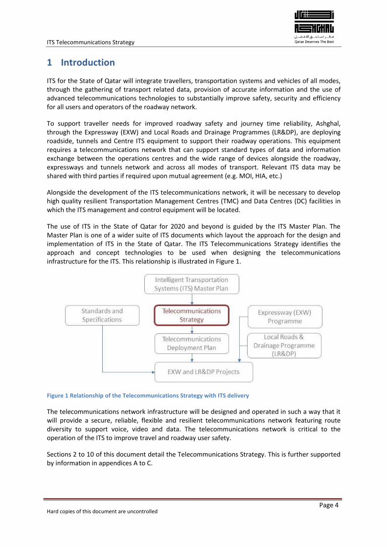
The use of ITS in the State of Qatar for 2020 and beyond is guided by the ITS Master Plan. The Master Plan is one of a wider suite of ITS documents which layout the approach for the design and implementation of ITS in the State of Qatar. The ITS Telecommunications Strategy identifies the approach and concept technologies to be used when designing the telecommunications infrastructure for the ITS. This relationship is illustrated in Figure 1.
Figure 1 Relationship of the Telecommunications Strategy with ITS delivery
The telecommunications network infrastructure will be designed and operated in such a way that it will provide a secure, reliable, flexible and resilient telecommunications network featuring route diversity to support voice, video and data. The telecommunications network is critical to the operation of the ITS to improve travel and roadway user safety.
Sections 2 to 10 of this document detail the Telecommunications Strategy. This is further supported by information in appendices A to C.
ITS Telecommunications Strategy
Hard copies of this document are uncontrolled
Page 5
2 Requirement for an ITS Telecommunications Strategy
The ITS Telecommunications Strategy outlines the approach to the procurement, building, operation and management a of telecommunications network that will then allow Ashghal to successfully deliver the outcomes of providing a world class multi-modal ITS for the State of Qatar.
Current ITS technology in the State of Qatar is connected over an Internet Protocol (IP) Virtual Private Network (VPN). The individual ITS sites around Qatar are connected to the Ooredoo public network which then aggregates all of the services and connects them to the Traffic Signal Control Room (TSCR) at the Ashghal office over a single high capacity fibre optic connection. The current arrangement however does not have any suitable Service Level Agreements (SLA) in place affecting operational performance and ultimately the credibility of the existing services.
The ITS Master Plan, Action Plan and ITS Architecture all establish that Qatar deserves the best ITS and this can only be realised if the ITS is supported by a robust and reliable telecommunications network. Whilst the ITS Master Plan and Action Plan detail the ITS strategies that will provide Qatar with the best ITS solutions, the ITS Telecommunications Strategy is necessary to describe how those strategies dependent upon a telecommunications network can be coordinated and delivered.
This document includes information on:
The key drivers and enablers
The challenges and inhibitors
The infrastructure model that the ITS telecommunications network will deliver
Recommendations for network architecture using best practice backbone design, including route diversity to link the various TMCs
The services that the ITS telecommunications network will deliver
The framework to guide the build, operate and manage roles.
The aims of the ITS Telecommunications Strategy are straightforward:
To demonstrate the need for a secure, reliable, flexible and comprehensive ITS telecommunications network and services
To highlight barriers that may constrain the deployment, operation and management of the ITS telecommunications network and to make recommendations that will address these barriers.
The ITS telecommunications network and services are a pre-requisite requirement for the delivery of the ITS project for the State of Qatar and therefore critical to the realisation of the Vision for the State of Qatar. It is therefore essential to communicate the benefits of the ITS telecommunications network to the Stakeholders for the ITS.
2.1 Purpose of the Telecommunications Deployment Plan
In conjunction with the Telecommunications Strategy, a Telecommunications deployment plan is being developed within the overall ITS Deployment Guidelines and associated standards. The proposed implementation will utilise the EXW Programme and the LR&DP to develop roll-out plans for the backbone telecommunications network. The deployment plan will consider the telecommunications infrastructure across the State of Qatar and will provide solutions for use in
ITS Telecommunications Strategy
Hard copies of this document are uncontrolled
Page 6
cities and rural areas, utilising not only the Ashghal network but also the network infrastructure of other network operators and service providers.
ITS Telecommunications Strategy
Hard copies of this document are uncontrolled
Page 7
3 Key Drivers and Enablers
Change in Qatar is driven by both the need to meet the Vision set out in the Qatar National Vision 2030 (QNV2030) and the vision for the ITS as set out in the ITS Master Plan. The drivers include:
A telecommunications network built and operated for the ITS across all transportation modes
Traffic and transport data acquisition in real time across all transport modes
Changes and advances in technology delivering internet based (e-commerce) services
Accurate traveller information provision
Traffic and traveller data management and archiving
Ongoing ITS equipment development and evolution which increasingly demands the use of higher bandwidth communications, i.e. higher resolution Closed Circuit Television (CCTV) cameras and encoders.
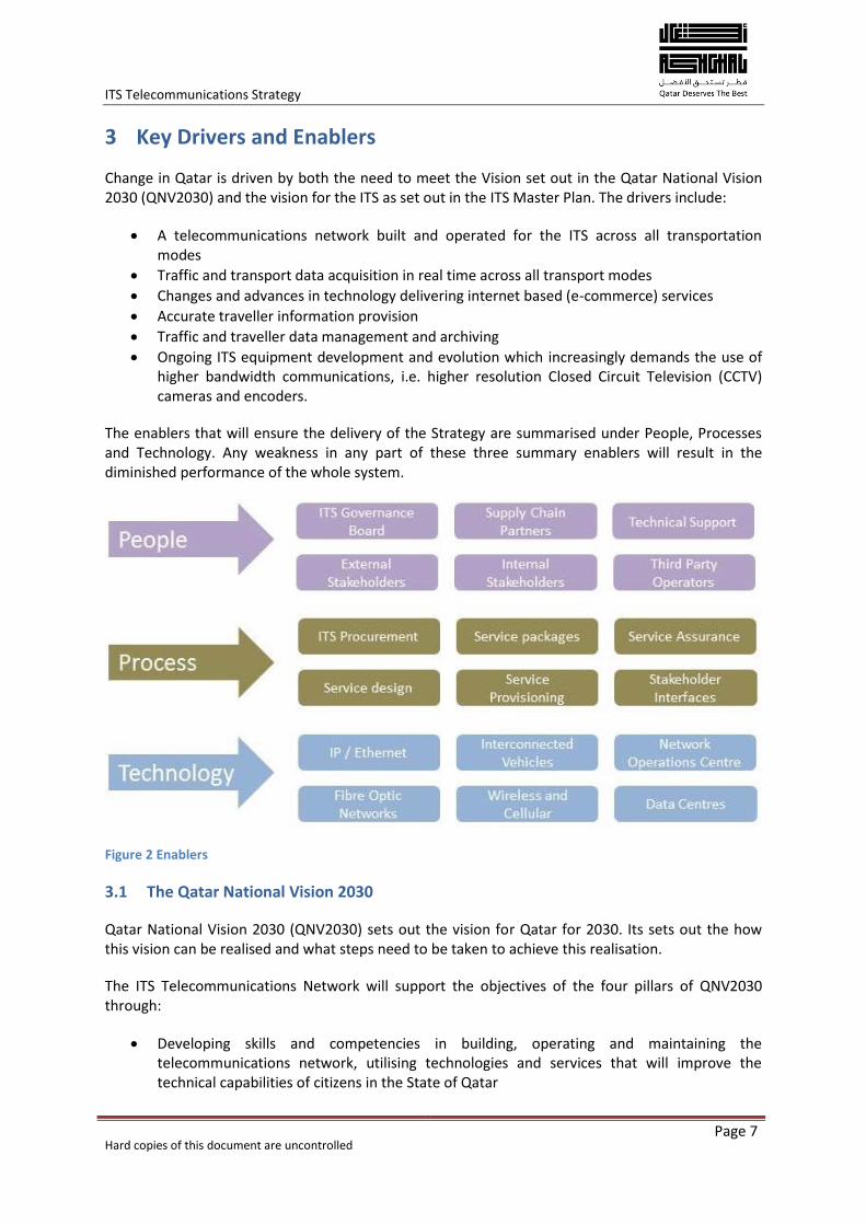
The enablers that will ensure the delivery of the Strategy are summarised under People, Processes and Technology. Any weakness in any part of these three summary enablers will result in the diminished performance of the whole system.
Figure 2 Enablers
3.1 The Qatar National Vision 2030
Qatar National Vision 2030 (QNV2030) sets out the vision for Qatar for 2030. Its sets out the how this vision can be realised and what steps need to be taken to achieve this realisation.
The ITS Telecommunications Network will support the objectives of the four pillars of QNV2030 through:
Developing skills and competencies in building, operating and maintaining the telecommunications network, utilising technologies and services that will improve the technical capabilities of citizens in the State of Qatar
ITS Telecommunications Strategy
Hard copies of this document are uncontrolled
Page 8
Allowing Qatar to become a major influence in innovation, research and design of ITS technologies across the Gulf Cooperation Council (GCC) states and encouraging economic development in the State of Qatar
Providing a telecommunication network that will support ITS technologies across all modes of transportation, improving journeys, reducing congestion and reducing both the number of incidents and the impact of incidents and the reducing the environmental effects of congestions and incidents
Provide transportation service providers and road users with high quality services in response to the needs of individuals and businesses.
3.2 The Vision for ITS
The Vision for ITS, as detailed in the ITS Master Plan 2014-2020 states that “By 2020, the State of Qatar will have the most accessible, efficient, safe and technologically advanced transportation network in the World.”
The telecommunications Infrastructure is a critical element in the deployment of the ITS infrastructure and contributes to meeting the overall ITS vision which:
Enables, supports and promotes a seamless and efficient multi-modal transportation network
Promotes and supports an inclusive transport infrastructure that will benefit the entire community
Helps ensure the competitive position of the State in national and international markets while addressing social and environmental objectives
Supplements the objectives, goals, and programmes outlined in the Transportation Master Plan for Qatar
Is supported by major stakeholders.
3.3 Roles and Responsibilities
The roles and responsibilities for ITS telecommunications will be managed through the ITS Governance Board as all of the participating agencies and Stakeholders have roles and responsibilities in the implementation and operation of the ITS and its telecommunications network.
Through the ITS Governance Board, the relevant team members from the Stakeholder groups will be fully engaged in the ITS implementation and they recognise not only their role in the implementation but also the benefits that they will derive from its successful implementation.
Primary roles and responsibilities for roadway ITS are with Ashghal, to ensure the successful deployment of ITS as part of the on-going infrastructure investment. Other Stakeholders that have significant roles and responsibilities include the Ministry of Interior (MOI), CRA, Mowasalat, etc.
It is the responsibility of the ITS Governance Board to ensure that suitable policies, regulations and operational agreements are in place to deliver the ITS telecommunications network through asset sharing agreements, network development policies, spectrum management policies and operational procedures and practices.
ITS Telecommunications Strategy
Hard copies of this document are uncontrolled
Page 9
3.4 Stakeholders
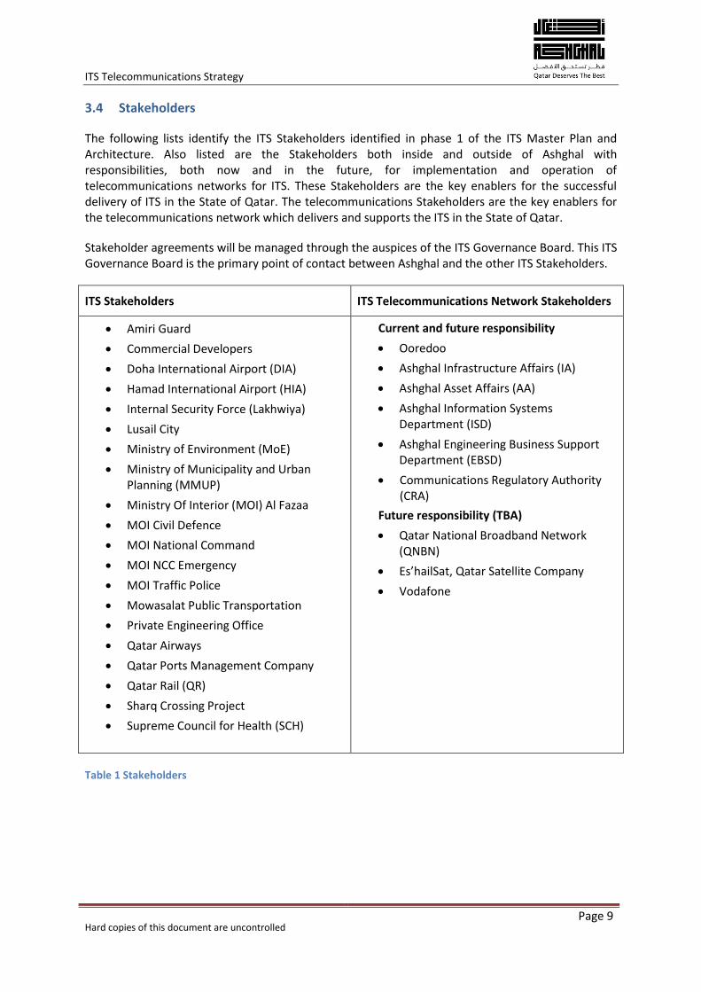
The following lists identify the ITS Stakeholders identified in phase 1 of the ITS Master Plan and Architecture. Also listed are the Stakeholders both inside and outside of Ashghal with responsibilities, both now and in the future, for implementation and operation of telecommunications networks for ITS. These Stakeholders are the key enablers for the successful delivery of ITS in the State of Qatar. The telecommunications Stakeholders are the key enablers for the telecommunications network which delivers and supports the ITS in the State of Qatar.
Stakeholder agreements will be managed through the auspices of the ITS Governance Board. This ITS Governance Board is the primary point of contact between Ashghal and the other ITS Stakeholders.
ITS Stakeholders ITS Telecommunications Network Stakeholders
Amiri Guard
Commercial Developers
Doha International Airport (DIA)
Hamad International Airport (HIA)
Internal Security Force (Lakhwiya)
Lusail City
Ministry of Environment (MoE)
Ministry of Municipality and Urban Planning (MMUP)
Ministry Of Interior (MOI) Al Fazaa
MOI Civil Defence
MOI National Command
MOI NCC Emergency
MOI Traffic Police
Mowasalat Public Transportation
Private Engineering Office
Qatar Airways
Qatar Ports Management Company
Qatar Rail (QR)
Sharq Crossing Project
Supreme Council for Health (SCH)
Current and future responsibility
Ooredoo
Ashghal Infrastructure Affairs (IA)
Ashghal Asset Affairs (AA)
Ashghal Information Systems Department (ISD)
Ashghal Engineering Business Support Department (EBSD)
Communications Regulatory Authority (CRA)
Future responsibility (TBA)
Qatar National Broadband Network (QNBN)
Es’hailSat, Qatar Satellite Company
Vodafone
Table 1 Stakeholders
ITS Telecommunications Strategy
Hard copies of this document are uncontrolled
Page 10
4 Telecommunications policies
4.1 Telecommunications Regulation in Qatar
The Communications Regulatory Authority (CRA) has the role of regulator for telecommunications in Qatar and is responsible for setting the legal frameworks to stimulate investment and lower market barriers for telecommunications. Qatar has adopted an open and competitive approach to telecommunications to encourage growth and investment and to encourage adoption of the latest technologies.
In June 2011, the CRA published “Advancing the Digital Agenda – Qatar’s National ICT Plan”. The plan details the government of the State of Qatar’s approach to creating a “vibrant ICT sector that will support the development of a knowledge economy and empower our people to use ICT to enrich their lives”. The plan also details the role of Qatar’s ICT infrastructure in the development of the country and outlines the services that will be developed to benefit the society of Qatar. These services include government shared-services platforms and a government payment platform. Other benefits of the plan include improving ICT education, building an ICT capable workforce and providing accessibility for all.
The following programmes and initiatives from the National ICT plan are closely related to, or directly impact the ITS Telecommunications Strategy:
Improving Connectivity through the building of a resilient high bandwidth network contributing to the national fibre network roll-out
Boosting Capacity by educating and developing engineers and technical resources through an ITS and telecommunications training programme
Fostering Economic Development through implementing an infrastructure on which e-commerce and e-government platforms can be developed and exploited
Enhancing Public Service Delivery through interconnectivity with Government telecommunications networks and data centres
Advancing Societal benefits through the use of emerging technologies and providing infrastructure to promote the use of internet based applications and technologies.
4.2 Radio Spectrum for ITS and Automotive applications
The CRA are also responsible for the regulation and management of radio spectrum in Qatar to ensure interoperability and fair use of the available spectrum. Spectrum allocations are based upon recognised standards developed and administered by the International Telecommunications Union (ITU) so that as far as is practicable, products developed in other parts of the world can be used in the State of Qatar.
There are a number of ITS applications and services which use radio communications as the communications medium. Recent developments in ITS and automotive application has led to the international standardisation of radio spectrum allocation through the ITU and other bodies such as the European Telecommunications Standards Institute (ETSI). This regulation is essential for two reasons
To protect spectrum and bandwidth so that it is only used for certain applications i.e. Emergency services
ITS Telecommunications Strategy
Hard copies of this document are uncontrolled
Page 11
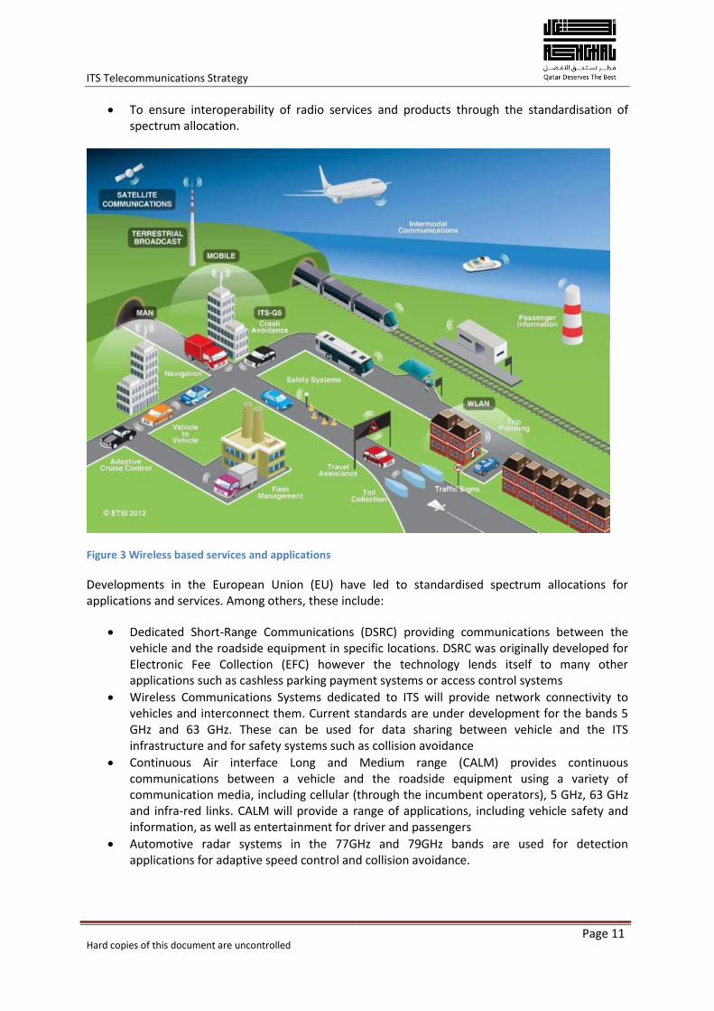
To ensure interoperability of radio services and products through the standardisation of spectrum allocation.
Figure 3 Wireless based services and applications
Developments in the European Union (EU) have led to standardised spectrum allocations for applications and services. Among others, these include:
Dedicated Short-Range Communications (DSRC) providing communications between the vehicle and the roadside equipment in specific locations. DSRC was originally developed for Electronic Fee Collection (EFC) however the technology lends itself to many other applications such as cashless parking payment systems or access control systems
Wireless Communications Systems dedicated to ITS will provide network connectivity to vehicles and interconnect them. Current standards are under development for the bands 5 GHz and 63 GHz. These can be used for data sharing between vehicle and the ITS infrastructure and for safety systems such as collision avoidance
Continuous Air interface Long and Medium range (CALM) provides continuous communications between a vehicle and the roadside equipment using a variety of communication media, including cellular (through the incumbent operators), 5 GHz, 63 GHz and infra-red links. CALM will provide a range of applications, including vehicle safety and information, as well as entertainment for driver and passengers
Automotive radar systems in the 77GHz and 79GHz bands are used for detection applications for adaptive speed control and collision avoidance.
ITS Telecommunications Strategy
Hard copies of this document are uncontrolled
Page 12
These developments form part of wider global initiatives on issues such as road safety (for example the European Commission's eSafety initiative) and road tolling. It is essential however that the spectrum for the services and applications are dedicated and allocated for ITS and that these adopted standards also align with those adopted by other GCC members. Radio spectrum, wireless applications and services are further detailed in Appendix C. Ultimately these applications and services will connect to the ITS Backbone network, as shown in Appendix D, together with Internet Service provider wireless telemetry.
4.3 Network Security
Whilst the technology and topology (refer to Appendix D) used for the ITS telecommunications network is similar to that of the public internet, the two networks are entirely separate. In this way, the security of the ITS telecommunications network is assured. Along with physical separation, hardware and software safeguards are in place to inhibit interference with the telecommunications network and its data traffic. The implementation of these safeguards ensures that the ITS telecommunications network meets the national ICS security standards prescribed by CRA (Ref: R4).
Third party access to the ITS network should be governed by an Ashghal security policy, in line with MOI standards.
ITS Telecommunications Strategy
Hard copies of this document are uncontrolled
Page 13
5 The ITS Telecommunications Network
5.1 Overview
The ITS telecommunications network will be responsible for implementing and managing Field-to-Centre (F2C) and Centre to Centre (C2C) communications as well as interfacing third party systems and access to these systems as needed.
The ITS operation requires a highly resilient and flexible telecommunications network that provides extremely high levels of availability. This will be achieved by means of alternate paths to link the various TMCs (route diversity) and the incorporation of redundant systems where critical services are required.
A range of business and safety critical systems and operations will be reliant upon the telecommunications network. Without extremely high levels of availability throughout the telecommunications network, ITS failures will impact all transportation modes, emergency services and the credibility of the State of Qatar to deliver a sustainable transportation network.
As an organisation, Ashghal is responsible for the management of a major infrastructure in the State of Qatar, primarily roadways, drainage and buildings. During the course of its normal day to day business, Ashghal will make business use of commercial telecommunications services. In building an ITS infrastructure, Ashghal will at the same time implement a telecommunications network, and be responsible for the supervision and monitoring of network operations. However Ashghal’s business operation will not change to the extent that it will also become a telecommunications network operator.
The telecommunications network will comprise a mix of technologies and services to deliver a set of integrated choices for how the network is delivered and how it is operated. (Further information on the available technologies is provided in Appendix C). These choices include:
Network access using the near-limitless capacity of optical fibre networks installed along the
Expressway and Locals Roads projects with some network gaps filled by Ashghal and through
the use of local wireless solutions
Network facilities leased / shared, with providers to fill in strategic gaps in the network
Remote services from public telecommunications service providers (Ooredoo and Vodafone)
over fixed links, wireless and satellite (Es’hailSat)
Wireless infrastructure and technology that will enable Vehicle to Vehicle (V2V) and Vehicle
to Infrastructure (V2I) platforms and services to be developed and implemented along with
wireless ITS technology.
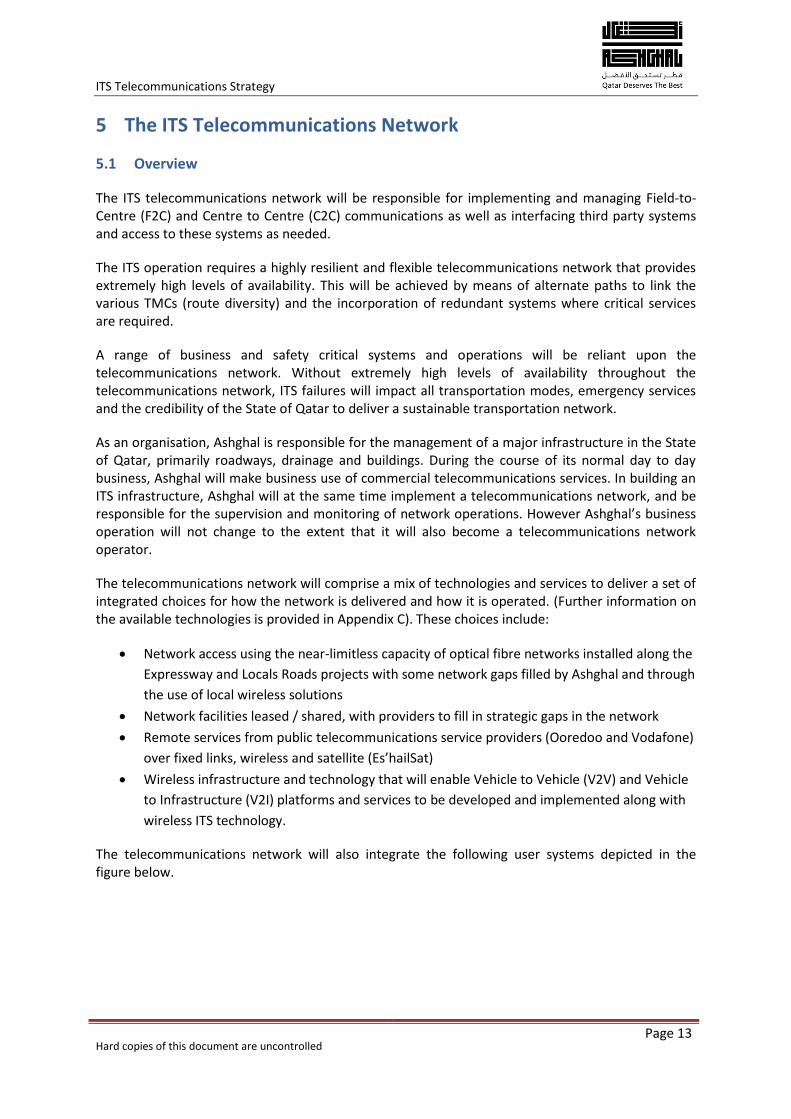
The telecommunications network will also integrate the following user systems depicted in the figure below.
ITS Telecommunications Strategy
Hard copies of this document are uncontrolled
Page 14
Figure 4 The overall ITS Telecommunications Network
5.2 Model and architecture for the ITS Telecommunications Network
The ITS Telecommunications Network features several interconnected networks:
A series of Local Area Networks (LAN) incorporating ITS devices deployed within a given scheme or project (ITS-LAN)
A Backbone Network (BN) connecting the various ITS-LANs together
A Wide Area Network (WAN) formed by the BN and the various ITS-LANs. This WAN may be considered the Principal Telecommunications WAN (PC-WAN), where “Principal” is the owner of the network (Ashghal).
The overall network architecture addresses the way in which networks are interconnected as well as the management schemes of packets moving through it.
5.2.1 Network architecture According to best practice network design, the network that will support ITS operations follows a hierarchical model which incorporates three layers:
The access layer, which supports the ITS-LAN
The distribution layer, which supports the interconnection of ITS-LANs. This layer is part of
the WAN
ITS Telecommunications Strategy
Hard copies of this document are uncontrolled
Page 15
The core layer, which supports C2C communications as well as other high-speed links to
Data centres, stakeholders, etc. This layer is also part of the WAN.
The various layers incorporate the following active equipment:
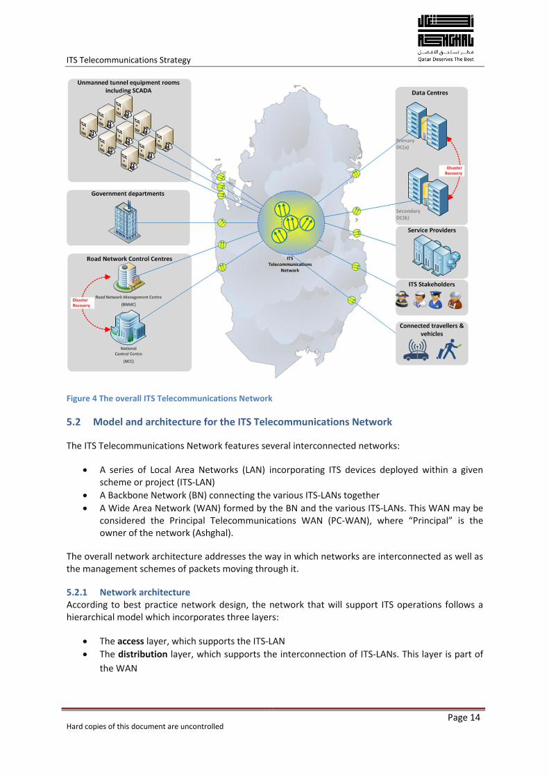
The access layer will consist of Access Nodes (AN) fitted with Layer-2 Gigabit Ethernet switches running on a mix of CAT 6 twisted-pair cables and fibre cabling. In some cases a microwave link may be required to facilitate “last mile” access. The access layer switches will have a minimum of 1 Gbps uplinks to the distribution layer
The distribution layer will consist of Distribution Nodes (DN) fitted with high port-count Layer-2 fibre switches that will be connected in a ring and ladder topology using 10 GbE fibres. The distribution layer will terminate at the various TMCs and Tunnel Control Centres on a Layer-3 switch. The use of a 10GbE backbone at this level ensures that high bandwidth data such as video images are dealt with accordingly
The core layer use Layer-3 Ethernet switches running either 10 GbE, 40 GbE up to 100 GbE over fibre as required by the overall WAN design. These switches will be installed at the TMCs and other sites such as Tunnel Control Centres only to provide access to the various Virtual LANs (VLANs) and subnets on the distribution layer. Centre to centre links will be accomplished using a dedicated Centre to Centre backbone incorporating redundant links that can be implemented over either fibre or via a third party service provider if required.
Figure 5 Hierarchical model for the ITS Telecommunications Network
Physical rings provide route diversity between the main network nodes so that a switch can be reached through various paths at both the access and distribution layers as well as at the core layer. Nevertheless, logical loops are to be avoided; in order to deliver a loop-free logical topology, the Multiple Spanning Tree Protocol (MSTP), will be used on the network switches.
ITS Telecommunications Strategy
Hard copies of this document are uncontrolled
Page 16
Apart from the inherent protection delivered by the ring and ladder topology, the WAN can incorporate redundant switches to improve network resilience on the distribution layer so if one switch fails, the WAN continues to operate.
5.2.2 Network segmentation The ITS telecommunications network is to be partitioned into different segments (users and services) through the use of Virtual LANs. VLANs are logical networks within a single physical network in which devices are assigned to LAN segments by software rather than by hardware. It is envisaged that each TMC shall be on its own VLAN. In addition, the video streams generated by CCTV should be segregated from the remaining ITS data at a minimum to allow for QoS rules (see Section 5.2.3) to be applied.
Additionally, due to the staging of multiple contracts and the creation of a large number of rings, the use of MSTP may be necessary to ensure spanning tree convergence; MSTP provides all the benefits of the Rapid Spanning Tree Protocol (RSTP) with the addition of allowing the network to be split into logical MST (Multi Spanning Tree) regions. It will also allow for the construction of VLAN specific spanning trees and hence can be used to implement an additional degree of load balancing across the network.
5.2.3 Quality of Service (QoS) Quality of service is the ability of a telecommunications network to provide different priority to different applications, users, or data flows, or to guarantee a certain level of performance to a data flow.
The VLANs implemented on the ITS network will carry services with varying bandwidth needs or pre-defined priorities; for this purpose an SLA (Service Level Agreement) with a distinct QoS (Quality of Service) must be set up on a per-service type and location basis.
The QoS implementation can be done on a physical port basis or on a per-VLAN basis. The implementation of QoS on the network will involve a clear definition of the various services and their associated bandwidth requirements at both the core and the distribution layers. It is recommended that this should be done at the outset of the design process to mitigate any risks involved with the implementation. A typical implementation for ITS systems would typically characterize the following service types:
Network overhead: Consists of network management traffic (e.g. SNMP, Spanning Tree BPDUs and is typically the highest priority)
Real-time/Time-sensitive data: Vehicle detector, DMS, ANPR images, etc.
CCTV video
Remaining network traffic on a “best-effort” basis.
5.2.4 Data flow The network will be designed such that data flows between road-side devices, servers and hosts follow pre-determined, predictable and redundant paths. The spanning trees setup as a result of the route diversity need to be carefully designed such that the information generated and shared does not unnecessarily overload the network hardware and plenty of spare capacity is available for future expansion.
ITS Telecommunications Strategy
Hard copies of this document are uncontrolled
Page 17
5.2.5 Benefits of the architecture The main benefits of the architecture proposed are the following:
The IP-based architecture provides for the transport of voice, video, and data over the same network infrastructure (network convergence)
The optic fibre ring and ladder topology and redundant equipment leverages data path diversity and combines high speed data rates with resilience and availability
The approach of a Layer-2 design for the access and distribution layers simplifies the network design, not affecting spanning tree convergence (due to MSTP) and dramatically reduces equipment costs
Traffic prioritization of time-sensitive and real-time network traffic enables a reliable quality of service for end user applications
Critical links between TMCs and Tunnel Control Centres allow for additional traffic shaping and result in high speed links between centres.
5.3 Topology of the ITS Telecommunications Network
The various Communications Nodes mentioned before will be housed in Ground Mounted Enclosures (GME) incorporating passive and active hardware as required by the relevant ITS scheme. The GME will meet the ITS specifications.
The Nodes will be interconnected by means of the following passive infrastructure depending on the type of roadway.
5.3.1 Expressway schemes On-scheme connections:
2 cables of 96 fibres each for the ITS LAN. Each cable (ITS LAN 1.1 and ITS LAN 1.2) shall be ducted individually and laid on each side of the road (whenever possible). Both cables constitute the looping path
2 cables of 96 fibres each for the PC WAN. Each cable (PC WAN 1.1 and PC WAN 1.2) will be ducted individually and laid on each side of the road (whenever possible). Both cables constitute the direct path for PC WAN and also carry the ITS direct return path (a redundant path for greater resilience in case of failover using MSTP protocol). These cables can also carry potential third-party access at Ashghal discretion
Access layer rings for each EXW scheme will be independent of access layer rings for adjacent EXW schemes terminating at the distribution switch at either end of the scheme.
Designers need to be aware of EXW schemes containing major intersecting roadways where the Limit of Work on the intersecting roadway interfaces with an adjacent EXW scheme (e.g. East/West corridor and Airport Road). In such instances, the ITS devices located on the intersecting roadway shall be part of its own access layer ring. (e.g. ITS located on Airport Road will not be a part of the access layer ring for East/West Corridor).
Inter-scheme connections:
1 cable of 96 fibres on each side of the road, ducted individually, for interconnection at a PC WAN level of adjacent schemes, Centre to Centre communications, etc.
Distribution nodes will need to be provided at major expressway intersections to enable possibilities for scheme interconnections as part of the overall WAN design.
ITS Telecommunications Strategy
Hard copies of this document are uncontrolled
Page 18
Local roads connections:
Distribution nodes will need to be provided with at interface points with local roads projects to allow for connectivity of these projects to EXW scheme’s WAN for backhaul to the operations centres.
5.3.2 Local roads schemes The number and type of cable will be identical to the Expressway schemes; in this case all four cables will be individually ducted along the median of the road where applicable.
Ducting within local roads schemes shall be designed to extend the WAN as far as possible through the local roads projects. Considerations should be made to design that ducting through local roads projects to provide a duct route between any adjacent EXW schemes that may be located at the project boundaries. In such situations, various local roads projects will need to co-ordinate to provide a continuous duct run through adjacent projects to connect binding EXW schemes. The purpose of this shall be to provide connectivity to various EXW schemes and allow for the staging and resilience of the overall WAN network design.
5.3.3 Interfaces The interface point with other schemes shall be the WAN GME, either at the end of scheme or as a mid-point interface within the scheme at major intersections.
A given scheme will always be terminated at least by a couple of diagonally opposed WAN GMEs matching the adjacent ones (see figures 15 and 17 for more detail).
5.3.4 Network switch topology The network switch layout presented serves as a model. However, the final layout depends on the detailed design for the particular scheme and on the required number of ITS LAN rings to be deployed based on RSTP convergence and switch recovery times.
For further guidance on the overall network topology, refer to the following drawings featured in Appendix D:
Figure 11: Proposed routing for Centre to Centre communications
Figure 12: High level topology for the ITS telecommunications Network
Figure 13: Fibre pathing for ITS LAN and PC WAN (Expressway schemes)
Figure 14: Fibre schematic for ITS LAN and PC WAN (Expressway schemes)
Figure 15: Fibre pathing for ITS LAN and PC WAN (Local Roads schemes)
Figure 16: Fibre schematic for ITS LAN and PC WAN (Local Roads schemes)
Figure 17: Network switch topology model
5.4 Deployment considerations (constructability)
This document is intended as a framework for all ITS designers to follow for designing the ITS LAN telecommunications network and WAN requirements for EXW and LRDP ITS schemes.
A re-evaluation has been required for fibre allocation, chamber sizes and cable slack required at GMEs, duct branches from the backbone duct network and the interfacing at the limits of work for each scheme.
ITS Telecommunications Strategy
Hard copies of this document are uncontrolled
Page 19
5.4.1 Fibre optic core allocation and splicing Specifically, this document introduces the following major changes within the ITS telecommunications design:
Splicing of fibre is shifted from ITS splice chambers to within the ITS GMEs (located at the Access Nodes)
Splicing within Access Nodes consists of 48 fibres being present, 24 fibres spliced through and 24 fibre pigtails laid up within the enclosure
Underground splicing occurs only for tunnel, pole mount or access enclosures which are not located along the local ITS backbone network by means of a 12 SM fibre optic drop cable
An additional 96 strand WAN trunk cable is introduced to accommodate scheme to scheme, scheme to centre, and centre to centre fibre connections
48 fibres from the WAN trunk are presented in Distribution Nodes with the remaining 48 coiled and laid up for future use.
For further detail, refer to Figure 18 in Appendix D which presents a guideline for the fibre core allocation for ITS LAN and PC WAN.
5.4.2 Fibre optic cable slack The following recommendations shall be followed when accounting for the amount of slack provided in the fibre optic trunk or drop cables. The existing specification or standard applies where a recommendation is not given.
For Access Node GMEs placed along the backbone duct network, 10m of slack in the ITS fibre optic trunk cable shall be provided within the Draw chamber directly adjacent the GME in either direction (i.e. going into and out of the GME). An additional 2m fibre optic slack cable shall be provided within the GME
For Access Node GMEs not on the backbone duct network, 10m of slack in the fibre optic drop cable shall be provided within the ITS chamber in either direction i.e. going into and out of the GME
2m of slack ITS trunk or drop cable (as applicable) shall be provided before and after the fibre optic patch panel within all Access Node GMEs
60m of slack in both the WAN and ITS fibre optic trunk cable shall be provided within the Draw chamber outside all Distribution Node GMEs at the project extents
2m of slack in both the WAN and ITS fibre optic trunk cables shall be provided in draw chambers that are pass-through. A pass-through chamber is defined as one with no direct connection to ITS devices or GMEs
10m of slack in both the WAN and ITS fibre optic trunk cables shall be provided in any chambers that involve a change in direction greater than 22.5 degrees
30 m of slack on each direction (total 60m) shall be provided for the WAN fibre optic trunk cable, within the draw chambers at major arterial or expressway intersections where the Limit of Work with the intersecting roadway is shared with an adjacent EXW scheme.
5.4.3 Chamber types The current Ashghal Civil & Structural Standards for ITS call out 3 types of chambers:
ITS Chambers (1m x 1m external)
Splice Chambers (1.4m by 1.4m external)
Draw Chambers (1.2m x 2.4m external)
ITS Telecommunications Strategy
Hard copies of this document are uncontrolled
Page 20
It is recommended that the following strategy should be used to evaluate the type of chamber that needs to be deployed at a given location. The existing specification or standard applies where a recommendation is not given.
Chambers used at extents of Limit of Works shall be Draw Chambers to accommodate the presence and slack requirements of Distribution nodes described before
Chambers used exclusively for pass-through of cable along the backbone duct network shall be Draw Chambers to facilitate easy hauling of cables
Chambers used for change in direction of backbone duct network shall be Draw Chambers to accommodate the bend radius for fibre optic cables during a change in direction
Chambers placed outside all Access Node GMEs along the backbone duct network shall be Draw Chambers to accommodate for the slack provided in the fibre optic trunk cables
Chambers placed outside all Distribution Node GMEs shall be Draw Chambers to accommodate for the slack provided in the fibre optic trunk cable
Chambers placed outside all Access Node GMEs that are not along the backbone duct network shall be ITS Chambers to accommodate for the slack in the drop cables
Chambers placed outside poles or structures supporting ducting between GMEs and end field devices shall be ITS Chambers.
5.4.4 Duct deployment and allocation The ducts are placed in a stack incorporating the following types of cables:
ITS LAN
WAN
SCADA
POWER
Power cables shall always be located at the bottom of the stack.
For further detail on the duct allocation and placement in stacks and chambers for Expressway schemes and Local Roads schemes, refer to Figure 19 in Appendix D.
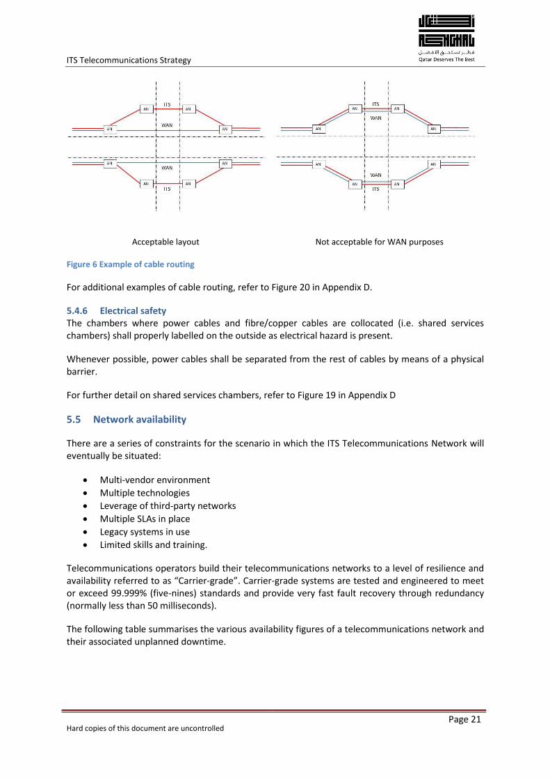
5.4.5 Cable routing at road junctions At road junctions, WAN and ITS cables are not to follow the same path: the WAN cable shall always follow a path as straight as possible (consider using directional drilling).
The reason for this is that the optical signal on the ITS looping path is regenerated in the Access Nodes switches; the optical signal on the WAN can only be regenerated in the Distribution Nodes either at both ends of the scheme or at mid-point presentations where access to the WAN is required.
Therefore, the WAN cable shall not be either over bent nor cut or spliced at intersections in order to minimise attenuation due to insertion losses such as splices or connectors and excessive bend radius. Otherwise, losses propagate across adjacent schemes compromising the overall optical link budget.
Additionally, the straight path reduces pulling resistance and stress for the cable taking into account the length of fibre cable reels (around 5-6 km).
ITS Telecommunications Strategy
Hard copies of this document are uncontrolled
Page 21
Acceptable layout Not acceptable for WAN purposes
Figure 6 Example of cable routing
For additional examples of cable routing, refer to Figure 20 in Appendix D.
5.4.6 Electrical safety The chambers where power cables and fibre/copper cables are collocated (i.e. shared services chambers) shall properly labelled on the outside as electrical hazard is present.
Whenever possible, power cables shall be separated from the rest of cables by means of a physical barrier.
For further detail on shared services chambers, refer to Figure 19 in Appendix D
5.5 Network availability
There are a series of constraints for the scenario in which the ITS Telecommunications Network will eventually be situated:
Multi-vendor environment
Multiple technologies
Leverage of third-party networks
Multiple SLAs in place
Legacy systems in use
Limited skills and training.
Telecommunications operators build their telecommunications networks to a level of resilience and availability referred to as “Carrier-grade”. Carrier-grade systems are tested and engineered to meet or exceed 99.999% (five-nines) standards and provide very fast fault recovery through redundancy (normally less than 50 milliseconds).
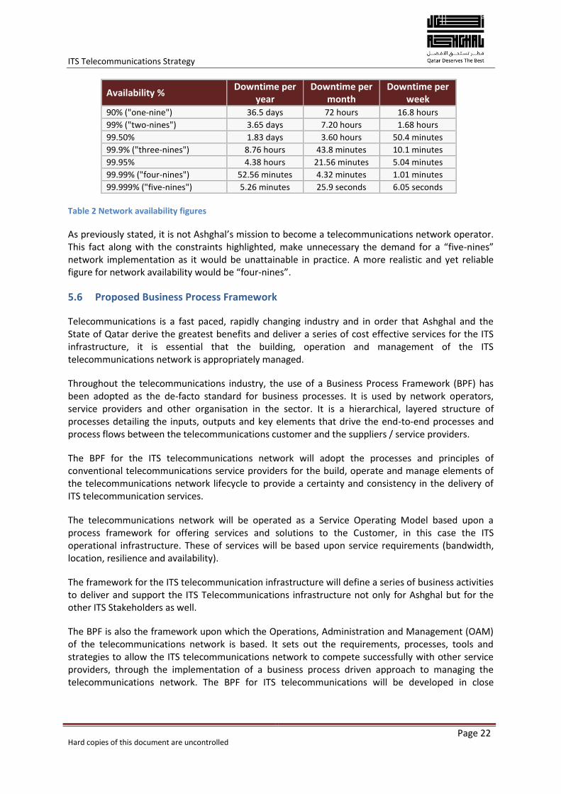
The following table summarises the various availability figures of a telecommunications network and their associated unplanned downtime.
ITS Telecommunications Strategy
Hard copies of this document are uncontrolled
Page 22
Availability % Downtime per
year Downtime per
month Downtime per
week 90% ("one-nine") 36.5 days 72 hours 16.8 hours
99% ("two-nines") 3.65 days 7.20 hours 1.68 hours
99.50% 1.83 days 3.60 hours 50.4 minutes
99.9% ("three-nines") 8.76 hours 43.8 minutes 10.1 minutes
99.95% 4.38 hours 21.56 minutes 5.04 minutes
99.99% ("four-nines") 52.56 minutes 4.32 minutes 1.01 minutes
99.999% ("five-nines") 5.26 minutes 25.9 seconds 6.05 seconds
Table 2 Network availability figures
As previously stated, it is not Ashghal’s mission to become a telecommunications network operator. This fact along with the constraints highlighted, make unnecessary the demand for a “five-nines” network implementation as it would be unattainable in practice. A more realistic and yet reliable figure for network availability would be “four-nines”.
5.6 Proposed Business Process Framework
Telecommunications is a fast paced, rapidly changing industry and in order that Ashghal and the State of Qatar derive the greatest benefits and deliver a series of cost effective services for the ITS infrastructure, it is essential that the building, operation and management of the ITS telecommunications network is appropriately managed.
Throughout the telecommunications industry, the use of a Business Process Framework (BPF) has been adopted as the de-facto standard for business processes. It is used by network operators, service providers and other organisation in the sector. It is a hierarchical, layered structure of processes detailing the inputs, outputs and key elements that drive the end-to-end processes and process flows between the telecommunications customer and the suppliers / service providers.
The BPF for the ITS telecommunications network will adopt the processes and principles of conventional telecommunications service providers for the build, operate and manage elements of the telecommunications network lifecycle to provide a certainty and consistency in the delivery of ITS telecommunication services.
The telecommunications network will be operated as a Service Operating Model based upon a process framework for offering services and solutions to the Customer, in this case the ITS operational infrastructure. These of services will be based upon service requirements (bandwidth, location, resilience and availability).
The framework for the ITS telecommunication infrastructure will define a series of business activities to deliver and support the ITS Telecommunications infrastructure not only for Ashghal but for the other ITS Stakeholders as well.
The BPF is also the framework upon which the Operations, Administration and Management (OAM) of the telecommunications network is based. It sets out the requirements, processes, tools and strategies to allow the ITS telecommunications network to compete successfully with other service providers, through the implementation of a business process driven approach to managing the telecommunications network. The BPF for ITS telecommunications will be developed in close
ITS Telecommunications Strategy
Hard copies of this document are uncontrolled
Page 23
cooperation with Ashghal Information Services Department (ISD) and the Engineering Business Support Department (EBSD).
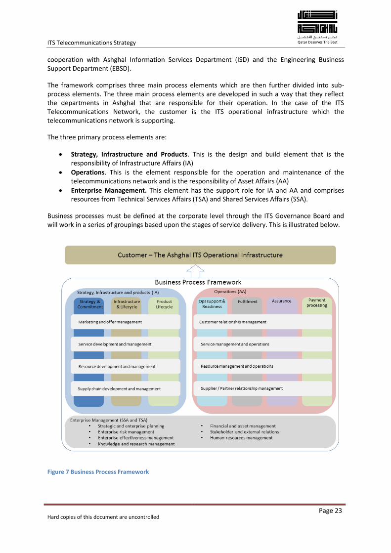
The framework comprises three main process elements which are then further divided into sub-process elements. The three main process elements are developed in such a way that they reflect the departments in Ashghal that are responsible for their operation. In the case of the ITS Telecommunications Network, the customer is the ITS operational infrastructure which the telecommunications network is supporting.
The three primary process elements are:
Strategy, Infrastructure and Products. This is the design and build element that is the responsibility of Infrastructure Affairs (IA)
Operations. This is the element responsible for the operation and maintenance of the telecommunications network and is the responsibility of Asset Affairs (AA)
Enterprise Management. This element has the support role for IA and AA and comprises resources from Technical Services Affairs (TSA) and Shared Services Affairs (SSA).
Business processes must be defined at the corporate level through the ITS Governance Board and will work in a series of groupings based upon the stages of service delivery. This is illustrated below.
Figure 7 Business Process Framework
ITS Telecommunications Strategy
Hard copies of this document are uncontrolled
Page 24
5.7 Alternatives for Operations, Administration and Maintenance
Activities in operating an in-house telecommunications network include the management of telecommunication services, networks and equipment, by means of designing generic and technology-specific architectures based on a series of functional requirements. This will also include determining information models, and protocols for the specification and management of Operation, Administration and Management (OAM) interfaces between network elements at the roadside and in vehicles, between roadside equipment and management systems and also between the various management systems. Ashghal will need to integrate the above activities in its business processes to successfully operate the telecommunications network for the ITS.
There are various OAM options to be examined when it comes to the telecommunications network for the ITS for the State of Qatar. These are:
A completely private network designed, operated and maintained by Ashghal. This will be developed through conventional contracting where Ashghal would manage separate contractors to operate and maintain the network with Ashghal undertaking network operations and management
A completely private network designed and built by Ashghal and maintained, operated and managed by a supply chain partner on behalf of Ashghal
A telecommunications network designed, built, operated and maintained by a tasked Government Agency
A telecommunications network designed, built, operated and maintained by a third party on a lease/concession basis owned by the Government.
In addition to these options, it should be recognised that the backbone will take a period of time to evolve to provide the infrastructure for the ITS and on occasions there will be a telecommunications network requirement at locations where the backbone network is not yet available. A dialogue will be established to seek suitable solutions and designs for filling in gaps in the network. In this way, asset sharing can be shown as a way of accelerating the network build-out without duplicating network build in already congested areas of Qatar.
Whichever procurement route is chosen, the arrangement must:
Encourage a long term strategic investment approach to the requirements of the ITS infrastructure
Provide a secure, reliable, flexible and resilient telecommunications network featuring route diversity
Provide a network built on open standards using off the shelf technology
Include an investment structure that will realistically spread the cost of building, operating and managing the network over the life of the contract
Include an active ICT asset management system and database. This system will include configurations details, layer management, asset monitoring, remote access to assets, together with configuration, version control and change management modules.
The development and implementation of the Telecommunications Network architecture for the ITS will be as a result of the outcome of the ITS procurement process. The detailed architecture for the telecommunications network will be based upon the capabilities and functionality of the core network equipment. The selection of core network elements, their installation and operation will be a critical outcome of the procurement process.
ITS Telecommunications Strategy
Hard copies of this document are uncontrolled
Page 25
The Procurement Strategy will detail the approach for procurement of all ITS equipment and services.
The telecommunications products and services that the ITS network will need are detailed in Appendix A. The implementation, monitoring and evaluation of the telecommunications network and facilities are further detailed in Appendix B. The technologies available for use in the ITS telecommunications network are detailed in Appendix C. Telecommunications backbone network diagrams are shown in Appendix D.
ITS Telecommunications Strategy
Hard copies of this document are uncontrolled
Page 26
6 Data Centres
6.1 Introduction
As with all telecommunication operations, the network is only as strong as its weakest link. The highest levels of resilience and availability need to pervade throughout the entire telecommunications network and this is particularly crucial at locations where the data is stored and managed.
The implementation of a high quality telecommunications network for the ITS and other systems will be dependent on equally high quality facilities to house the equipment and systems that operate and manage the ITS. The use of purpose built Data Centres (DC) will address this requirement and will ensure that the investment in the ITS and the telecommunications infrastructure is not eroded.
The data centres themselves will be implemented on a “five-nines” approach as they are constitute discrete network locations with the following characteristics:
Controlled environment.
Bespoke facilities
Dedicated support 24/7
Resilient infrastructure.
The existing installed ITS equipment in and around Doha is currently controlled at the Traffic Signal Control Room (TSCR) located at the Ashghal head office (Al Faisal Tower 2) in West Bay. Whilst the location is suited to the existing levels of equipment deployed in Doha, it has insufficient capacity to expand and deliver the required levels of capability and resilience for future ITS deployments.
In the long term (post 2016/2017), all ITS will be managed and controlled from the National Transportation Management Centre (NTMC) on the Al Shamal road. In the medium term (late 2015), installed ITS equipment will be controlled from the Road Network Management Centre (RNMC) at Ashghal Roads Operations and Maintenance (O&M) office on Wholesale Market Road. This means that in the period up until the delivery of the RNMC, ITS will be controlled and managed from a facility with limited capability and very limited capacity. Further information on the telecommunications network deployment timescales are provided in Appendix B.
The TSCR in its current form cannot expand and has very limited resilience. Data storage is in the form of tapes, stored off site however there is no resilience for any of the systems located at the TSCR. The RNMC is still at the design stage and will not be available until the end of 2015. This leaves a break in the capability for Ashghal to operate a resilient ITS control facility with acceptable levels of Disaster Recovery and resilience.
6.2 Options
To enable a step change in the operation and management of ITS, suitably managed DC facilities are required and there are a number of options that can address this.
Option 1
Ashghal rent equipment space from existing DC providers. This will offer:
ITS Telecommunications Strategy
Hard copies of this document are uncontrolled
Page 27
Secure space in a highly controlled environment
Staff to operate and maintain the data equipment and critical systems
Site resilience and DR for critical systems
Expansion space
Reduced total cost of ownership
Connection of the DC to the TSCR for continued operations.
This option can deliver tangible benefits in the short term (6-12 months) until the RNMC is operational.
Option 2
Ashghal to build and operate their own DC facilities. This will require that:
Ashghal own and operate at least 2 DCs
Ashghal build and maintain a high grade telecommunications network between the two sites and the ITS equipment.
This option can only deliver the full benefit once both DCs are available.
Option 3
A combination of the two previous options whereby Ashghal rent space in an existing DC whilst a second DC facility is being built. This combination will allow Ashghal to install ITS systems into a resilient and secure environment in a short timescale. The DC will be connected to the TSCR through a resilient telecommunications network delivered by one of the available service providers.
Option 3 will deliver the most appropriate outcome for the use of DC facilities. It will allow Ashghal to expand their ITS capability in a short timescale and deliver the high levels of resilience that the ITS management requires.
Development and delivery of the DC facilities for the ITS will need to be carefully managed through very close liaison with the Information Services Department (ISD) within Ashghal. ISD are responsible for the management of Ashghal’s IT infrastructure and telecommunications services. Plans are being developed by ISD to deliver enhanced services and facilities for Ashghal and the development of ITS services will need to be included as part of those plans.
Once the upgraded facilities are in place and operational, ISD will continue to be a major Stakeholder in the ongoing Operations, Administration and Management (OAM) of the services and facilities and will be an internal supplier to the ITS operation.
ITS Telecommunications Strategy
Hard copies of this document are uncontrolled
Page 28
7 Key Challenges and Inhibitors
7.1 Providing a Future Proof network
Through the use of Ethernet and IP over fibre optics and radio, the Ashghal ITS Telecommunications Network will be as future proof as is possible to achieve with current and foreseeable technology whilst remaining cost effective. Using Ethernet and fibre optics as the network infrastructure, future designs and improvements will be driven though innovations with control and management applications and end devices.
The availability of high levels of data and information from the roadway network will lead to future development that will use the data for new applications aimed at improving journey time reliability and road safety and through connecting Stakeholders to the Ashghal ITS, the information and data can be shared and used to offer improved services and data uses.
7.2 Operations
At present Ashghal procure ITS telecommunications services through a third party service provider. With the construction and delivery of its own telecommunications network, Ashghal will need to put in place the appropriate operational management to ensure that the investment is not eroded.
Operational Support Systems (OSS) will need to be developed to provide the expected service levels for the ITS infrastructure, providing processes and personnel in three primary dimensions:
Customer facing (providing the services for the ITS operation)
Partner facing (third party operators and traveller service providers)
Network facing (keeping the telecommunications network running).
Software systems are available to help deliver these processes but Ashghal will still need the personnel to deliver the services.
7.3 Resources and skills
ITS telecommunications Human Capacity Building (HCB) will be the primary vehicle for educating the current and emerging transportation workforce about ITS telecommunication technologies. The HCB task will need to link telecommunication practitioners and decision makers with suppliers, instructors and trainers, and peers to advance the position of Ashghal’s ITS telecommunications capability.
The ITS telecommunications HCB task is to develop a telecommunications profession within Ashghal and its major supply chain partners, taking the lead in the innovative use of telecommunications technologies. This programme will need to comprise of four primary elements:
Collaboration
Innovative thinking
An ITS customer-focused strategy
A results-driven approach.
The primary focus of a telecommunications HCB task will be on building a telecommunications professional capacity and developing the future telecommunications workforce. The task will seek to
ITS Telecommunications Strategy
Hard copies of this document are uncontrolled
Page 29
influence the most informative and effective learning structures to provide the latest in best practices in telecommunications delivery and research to the Ashghal workforce and its supply chain. The task will need to support activities that deliver multi-technology telecommunications learning opportunities to the engineering community by:
Encouraging knowledge sharing of best practices
Providing technical assistance to telecommunication technology engineers through Peer-to-Peer (P2P) and formal training programmes
Delivering telecommunications technology training through suppliers and partners.
A set of core components provide a basis for the tasks four interrelated outcomes are:
Professional development, which seeks to equip current and emerging telecommunication professionals with the knowledge, skills, and abilities to plan, design, deploy, operate, and maintain ITS telecommunication technologies
Leadership Outreach which includes the development of a network of champions who promote the value of ITS telecommunications
Knowledge Exchange to facilitate the exchange of knowledge through innovative solutions
Technology Transfer to accelerate technology transfer to bring ITS telecommunications research and proven solutions to the user community.
Put into action, the four components and outcome areas support a strategic approach for training delivery that seeks to connect the workforce, accelerate the adoption of ITS telecommunication technologies, deliver learning in the most effective and engaging manner, and continuously evaluate the learning programme for maximum impact.
ITS Telecommunications Strategy
Hard copies of this document are uncontrolled
Page 30
8 Budgetary Estimates
The cost and completion timescales for the ITS telecommunications network will depend upon a range of factors, including:
Programme management of adjacent schemes
Access to third party networks
Availability of skilled labour available to build and maintain the network
Coordination between Ashghal and other parties
Material supplies
Operational capabilities and knowledge of telecommunications requirements around specific technologies and data services required between field devices to centres.(F2C)) centres to field devices, (C2F) and in centre to centre communications, (C2C).
With good planning practices, the risks inherent in such a large scale infrastructure project can be mitigated so that the network can be completed in the most cost effective manner.
As of September 2013 [Ref: R5], ITS equipment located at 44 junctions in and around Doha is connected to the TSCR using a VPN provided by Ooredoo. Each of the 44 connections (CCTV cameras and Traffic signal controllers) costs Ashghal QAR 4,550 per month, a total of QAR 200,202 per month (or QAR 2,402,400 per annum). If these figures were extrapolated to include all future connections of ITS equipment, the costs will rise to many millions of QAR per month.
Much of the cost of the proposed ITS telecommunications network, around 90%, is already included as part of the overall ITS cost estimate for each scheme. Included in these costs are:
Fibre optic cable for the ITS equipment locations (the Access network)
Fibre optic cable for the Backbone network, connecting the sections of Access network together and to the TMCs and DCs
The Layer 2 IP switch located at the Ground Mounted Enclosure, local to the roadside ITS equipment
The fibre optic splicing and terminations in the Access and backbone networks
The Layer 2 and Layer 3 IP equipment located in the WAN/Backbone networks.
Costs excluded are:
Infrastructure and facilities at the RNMC, NTMC and TSCR
Network management system (hardware and software) for OAM of the telecommunications network
Leased network costs from Ooredoo and QNBN for telecommunications network gap infill when required
SCADA network
Dedicated fibre cable for Centre to Centre communications
Operational Expenditure (opex) costs.
As a comparison, the Capital Expenditure (capex) of the entire proposed telecommunications infrastructure for all of the current planned ITS schemes is approximately QAR 359,3 million. This equates on average to 7% of the total ITS infrastructure capex over the ITS project period. This is illustrated in the table below.
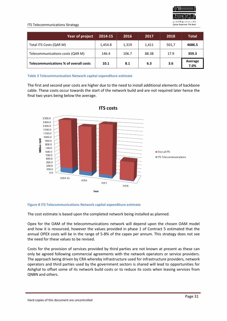
ITS Telecommunications Strategy
Hard copies of this document are uncontrolled
Page 31
Year of project 2014-15 2016 2017 2018 Total
Total ITS Costs (QAR M) 1,454.8 1,319 1,411 501,7 4686.5
Telecommunications costs (QAR M) 146.4 106.7 88.38 17.9 359.3
Telecommunications % of overall costs 10.1 8.1 6.3 3.6 Average
7.0%
Table 3 Telecommunication Network capital expenditure estimate
The first and second year costs are higher due to the need to install additional elements of backbone cable. These costs occur towards the start of the network build and are not required later hence the final two years being below the average.
Figure 8 ITS Telecommunications Network capital expenditure estimate
The cost estimate is based upon the completed network being installed as planned.
Opex for the OAM of the telecommunications network will depend upon the chosen OAM model and how it is resourced, however the values provided in phase 1 of Contract 5 estimated that the annual OPEX costs will be in the range of 5-8% of the capex per annum. This strategy does not see the need for these values to be revised.
Costs for the provision of services provided by third parties are not known at present as these can only be agreed following commercial agreements with the network operators or service providers. The approach being driven by CRA whereby infrastructure used for infrastructure providers, network operators and third parties used by the government sectors is shared will lead to opportunities for Ashghal to offset some of its network build costs or to reduce its costs when leasing services from QNBN and others.
ITS Telecommunications Strategy
Hard copies of this document are uncontrolled
Page 32
The expenditure for telecommunications services operating over the infrastructure of mobile telephony network providers will again depend on the commercial agreements entered into however the capex for the base equipment is anticipated to be in the range of QAR 5,000 – 10,000 with a monthly opex in the range QAR 750 – 1,000 depending on the bandwidth requirements and the Service Level Agreements put in place.
The Capital costs for the equipping of the Data Centre (racks, server chassis’ cabling and telecommunications infrastructure) over the ITS construction period is approximately QAR 60 million with QAR 20 million required for the first year. The first year costs include the initial base infrastructure at the data centre (racks, cabling, hardware chassis’ and network management infrastructure) and over the following years network elements (hard disk storage, server capacity and management software) will be incremented as the ITS roadside infrastructure is deployed. Like the telecommunications network, the opex for the OAM of the DC is anticipated at 5-8 % however this is very dependent upon the procurement model used and the extent to which the infrastructure is shared with other Ashghal operations and services.
ITS Telecommunications Strategy
Hard copies of this document are uncontrolled
Page 33
9 Outcomes and Benefits
The telecommunications network for the ITS will enable the full range of ITS services and applications to be delivered across the State of Qatar. The network will deliver the required levels of availability of 99.99% and deliver a flexible and robust infrastructure designed for mission critical service delivery.
The outcomes and benefits of the Strategy are detailed below. The outcomes are the desired results to be achieved through the delivery of the strategy. The benefits are the measurable deliverables that the outcomes will deliver.
Outcomes
Development and use of a Business Process Framework for the building, operation and management of the telecommunications network and subsystems
Delivering a network that has the capability to be used for other services e.g. drainage SCADA and Ashghal Enterprise IT
A network flexible enough to accommodate a wide range of ITS technologies without excessive physical reconfiguration
Development of a range of services to provide an array of ITS connectivity solutions
Open, standards based interfaces to allow interconnectivity with other Stakeholders and sharing of services from ITS systems, (CCTV etc.)
Provide a first choice alternative to commercial network service providers
Enabling future connected vehicle technologies
A framework for the delivery, operation and management of all ITS related services and applications
Telecommunications Supplier / Partner relationships based upon measured performance and service delivery of core ITS related telecommunications services
A reliable network that connects safety and business critical systems to the TMCs
Strategic Telecommunications Infrastructure designed for flexible and robust service delivery.
Benefits
Enhanced network bandwidth and improvements to service capability
Improved response times for service delivery and restoration
Resilient, self-healing network delivering extremely high levels of availability
Highest possible network availability through the design, implementation and operation of the telecommunications network
A trained and educated workforce.
ITS Telecommunications Strategy
Hard copies of this document are uncontrolled
Page 34
10 Next Steps
In order to deliver the ITS telecommunications network to meet the requirements of this strategy, it is essential that a series of actions are immediately undertaken by Ashghal along with telecommunications network operators, service providers and ITS stakeholders.
Ashghal will need to adopt new ways in which some of their business operations are carried out including the transition from network build to network operations. Targets for the implementation of the telecommunications network will need to be agreed and action plans put in place to deliver to these targets.
The telecommunications network will need to be in place to meet the operational ITS start dates for the various EXW and LR&DP schemes and for the RNMC (late 2015), the NTMC (late 2017) and Data Centres (date still TBA) to be interconnected.
With the leadership and support from the ITS Governance Board the telecommunications network will be achieved, leading to the realisation of the benefits delivered through the ITS.
The following steps must be taken in order that the outcomes and benefits of the Strategy are realised.
Build a formal working relationship with CRA to implement the ITS telecommunications network and to contribute to the delivery of the Qatar National Broadband Plan and National ICT Strategy
Identify the core network elements that need to be procured through third party network access agreements
Engage fully with Ashghal ISD and EBSD to implement a BPF that will allow Ashghal to define, deliver, operate and maintain all of the services and applications that the ITS telecommunications network will deliver
Following the launch of the ITS Master Plan, engage with other transportation stakeholders to put in place a suitable mechanism for the integration of the various telecommunications networks
Develop and implement a HCB programme to recruit, train and develop a local resource to operate and manage the ITS telecommunications network
Manage the deployment of the ITS telecommunications network through the EXW and LR&D programmes.
The involvement of stakeholders in the next steps for the Telecommunications Strategy is detailed in the following RACI matrix.
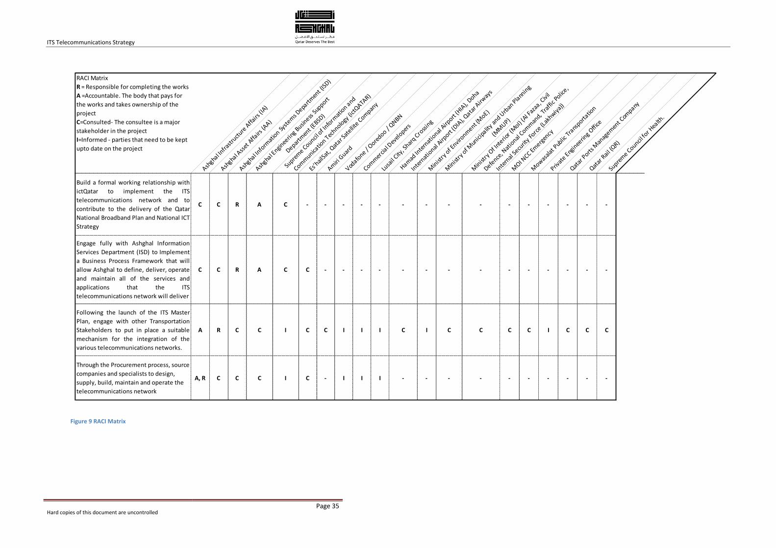
ITS Telecommunications Strategy
Hard copies of this document are uncontrolled
Page 35
Figure 9 RACI Matrix
RACI Matrix
R = Responsible for completing the works
A =Accountable. The body that pays for
the works and takes ownership of the
project
C=Consulted- The consultee is a major
stakeholder in the project
I=Informed - parties that need to be kept
upto date on the project
Ashgha
l Infra
stru
cture
Affa
irs (I
A)
Ashgha
l Ass
et A
ffairs
(AA)
Ashgha
l Info
rmat
ion Sy
stem
s Depa
rtmen
t (IS
D)
Ashgha
l Engin
eerin
g Busin
ess S
upport
Departm
ent (
EBSD)
Supre
me C
ouncil o
f Info
rmat
ion a
nd
Comm
unicatio
n Tec
hnology
(ict
QATAR)
Es’h
ailSa
t, Qat
ar Sat
ellite
Compan
y
Amiri
Guar
d
Vodafo
ne / O
oredoo /
QNBN
Comm
ercia
l Dev
eloper
s
Lusa
il City
, Shar
q Cro
ssin
g
Hamad
Inte
rnat
ional
Airport
(HIA
), Doha
Inte
rnat
ional
Airport
(DIA
), Qata
r Airw
ays
Min
istry
of E
nvironm
ent (M
oE)
Min
istry
of M
unici
palit
y an
d Urb
an P
lann
ing
(MM
UP)
Min
istry
Of I
nterio
r (M
oI) (A
l Faz
aa, C
ivil
Defence
, Nat
ional
Comm
and,
Tra
ffic P
olice,
Inte
rnal
Secu
rity
Forc
e (L
akhwiy
a))
MOI N
CC Emerg
ency
Mow
asala
t Pub
lic T
rans
portatio
n
Privat
e Eng
inee
ring
Office
Qatar
Ports
Man
agem
ent C
ompany
Qatar
Rai
l (QR)
Supre
me C
ouncil fo
r Hea
lth.
Build a formal working relationship with
ictQatar to implement the ITS
telecommunications network and to
contribute to the delivery of the Qatar
National Broadband Plan and National ICT
Strategy
C C R A C - - - - - - - - - - - - - - -
Engage fully with Ashghal Information
Services Department (ISD) to Implement
a Business Process Framework that will
allow Ashghal to define, deliver, operate
and maintain all of the services and
applications that the ITS
telecommunications network will deliver
C C R A C C - - - - - - - - - - - - - -
Following the launch of the ITS Master
Plan, engage with other Transportation
Stakeholders to put in place a suitable
mechanism for the integration of the
various telecommunications networks.
A R C C I C C I I I C I C C C C I C C C
Through the Procurement process, source
companies and specialists to design,
supply, build, maintain and operate the
telecommunications network
A, R C C C I C - I I I - - - - - - - - - -
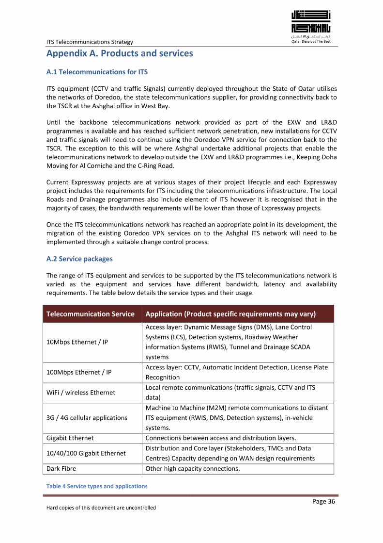
ITS Telecommunications Strategy
Hard copies of this document are uncontrolled
Page 36
Appendix A. Products and services
A.1 Telecommunications for ITS
ITS equipment (CCTV and traffic Signals) currently deployed throughout the State of Qatar utilises the networks of Ooredoo, the state telecommunications supplier, for providing connectivity back to the TSCR at the Ashghal office in West Bay.
Until the backbone telecommunications network provided as part of the EXW and LR&D programmes is available and has reached sufficient network penetration, new installations for CCTV and traffic signals will need to continue using the Ooredoo VPN service for connection back to the TSCR. The exception to this will be where Ashghal undertake additional projects that enable the telecommunications network to develop outside the EXW and LR&D programmes i.e., Keeping Doha Moving for Al Corniche and the C-Ring Road.
Current Expressway projects are at various stages of their project lifecycle and each Expressway project includes the requirements for ITS including the telecommunications infrastructure. The Local Roads and Drainage programmes also include element of ITS however it is recognised that in the majority of cases, the bandwidth requirements will be lower than those of Expressway projects.
Once the ITS telecommunications network has reached an appropriate point in its development, the migration of the existing Ooredoo VPN services on to the Ashghal ITS network will need to be implemented through a suitable change control process.
A.2 Service packages
The range of ITS equipment and services to be supported by the ITS telecommunications network is varied as the equipment and services have different bandwidth, latency and availability requirements. The table below details the service types and their usage.
Telecommunication Service Application (Product specific requirements may vary)
10Mbps Ethernet / IP
Access layer: Dynamic Message Signs (DMS), Lane Control
Systems (LCS), Detection systems, Roadway Weather
information Systems (RWIS), Tunnel and Drainage SCADA
systems
100Mbps Ethernet / IP Access layer: CCTV, Automatic Incident Detection, License Plate
Recognition
WiFi / wireless Ethernet Local remote communications (traffic signals, CCTV and ITS
data)
3G / 4G cellular applications
Machine to Machine (M2M) remote communications to distant
ITS equipment (RWIS, DMS, Detection systems), in-vehicle
systems.
Gigabit Ethernet Connections between access and distribution layers.
10/40/100 Gigabit Ethernet Distribution and Core layer (Stakeholders, TMCs and Data
Centres) Capacity depending on WAN design requirements
Dark Fibre Other high capacity connections.
Table 4 Service types and applications
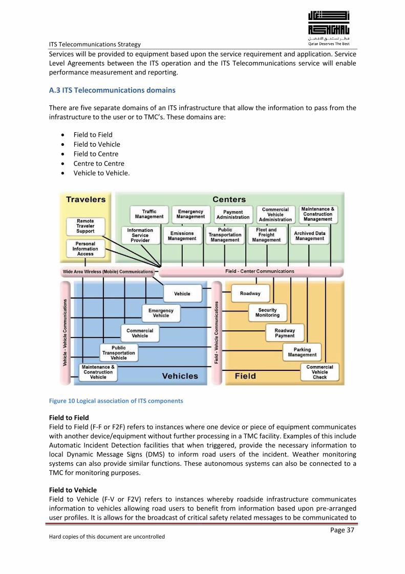
ITS Telecommunications Strategy
Hard copies of this document are uncontrolled
Page 37
Services will be provided to equipment based upon the service requirement and application. Service Level Agreements between the ITS operation and the ITS Telecommunications service will enable performance measurement and reporting.
A.3 ITS Telecommunications domains
There are five separate domains of an ITS infrastructure that allow the information to pass from the infrastructure to the user or to TMC’s. These domains are:
Field to Field
Field to Vehicle
Field to Centre
Centre to Centre
Vehicle to Vehicle.
Figure 10 Logical association of ITS components
Field to Field Field to Field (F-F or F2F) refers to instances where one device or piece of equipment communicates with another device/equipment without further processing in a TMC facility. Examples of this include Automatic Incident Detection facilities that when triggered, provide the necessary information to local Dynamic Message Signs (DMS) to inform road users of the incident. Weather monitoring systems can also provide similar functions. These autonomous systems can also be connected to a TMC for monitoring purposes.
Field to Vehicle Field to Vehicle (F-V or F2V) refers to instances whereby roadside infrastructure communicates information to vehicles allowing road users to benefit from information based upon pre-arranged user profiles. It is allows for the broadcast of critical safety related messages to be communicated to
ITS Telecommunications Strategy
Hard copies of this document are uncontrolled
Page 38
vehicles in the event of emergencies, incidents or weather related road conditions. This domain also allows for field devices to derive information from vehicle based systems that can be used to inform other systems. An example of this will be “Floating Vehicle Data” (FVD) where the data from the vehicles journey is shared with the applications at the TMC to analyse journey time and congestion.
Field to Centre Field to Centre (F-C or F2C) refers to the instance where data originating from roadside devices is communicated back to a TMC or similar facility. Example of this include network surveillance CCTV images transmitted to a TMC or traffic flow data from carriageway based traffic detection devices informing traffic databases for immediate and future analysis. This domain also includes the information and data transmission from the centre to the field i.e. providing messages to DMS or information and data for onward transmission to vehicles in the F-V domain.
Centre to Centre Centre to Centre (C-C or C2C) refers to instances where data and information is communicated between two or more TMC’s or between a TMC and another data management facility. Examples of this include data replication between a main and a stand-by TMC or between a TMC and an third party data facility providing internet based information to road users and travellers. As the ITS system for Qatar will adopt a multi-modal approach, C-C communications will allow all public transport operators (road, rail, metro and buses) to share data and information.
It should be appreciated that the above 4 domains will not operate as separate entities rather they will make up the entire system. Information and data on occasions will be derived and disseminated across multiple domains.
Vehicle to Vehicle Vehicle to Vehicle (V-V or V2V) is the anonymous communications between vehicles whereby data regarding speed, direction and location are exchanged to allow the vehicles to develop an awareness of other traffic. It is primarily a safety based form of communication aimed at sharing information about threats, hazards and traffic conditions. Technology for V2V is still in development without a clear set of international standards fully in place.
A.4 E-Commerce and e-government
The integration of the networks of the various Stakeholders will enable the development and launching of e-commerce and e-government applications to the market in Qatar taking in future Cloud computing opportunities. Integrated (Multi-modal) ticketing systems, electronic bill payment and on-line transactions will all be enabled through the ITS telecommunications network and the implementation of Electronic Data Interchange (EDI) applications and services. Service can include Traffic Violation Penalty Management, Real-time mobile penalty payment systems for the MOI (Traffic Police) and mobile payment systems using smart phone applications.
The CRA has recognised that Cloud computing will play an important role in future e-commerce applications and the 2010 e-commerce law will allow businesses in Qatar to develop innovative online business models and offerings. This will also allow the development of travel oriented mobile data applications.
A.5 Mobile data applications
Information from the TMC and the control centres of other stakeholders will be made available to mobile application service providers. In this way, journey planning and travel advice applications can be developed and rolled out. This will require the provision of connections from the TMCs and
ITS Telecommunications Strategy
Hard copies of this document are uncontrolled
Page 39
Stakeholder control centres to the networks of Ooredoo and Vodafone will allow mobile phone based applications to be deployed.
The deployment of future services whereby the ITS infrastructure communicates directly with vehicles for applications such as queue warning, advance incident information or hazard warning systems will be developed for future deployment. Building a telecommunications network based upon Ethernet applications over a fibre optic network to roadway based equipment will allow future applications and services to be developed with minimal additional infrastructure investment.
The use of Machine to Machine (M2M) services from cellular telephony service providers will allow Ashghal to operate and manage remote equipment at any time including ITS roadside equipment and some CCTV facilities. M2M services can be used for in-car functions such as “infotainment”, vehicle diagnostics and road safety applications. The use of M2M applications will require a strong operational relationship with the cellular service provider. This relationship is a further opportunity for asset sharing.
A.6 Connectivity, Control Centres and Data Centres
The telecommunications network will provide the critical link between Transportation Management Centres and Control Centres for other ITS Stakeholders. This can be either through a Pan-Government Wide Area Network (WAN) connecting to the Stakeholders separate sites around Qatar or through the interconnectivity of government data centres used by the Stakeholders. It will be through the Data centres that access to Cloud based services will be provided along with access to historical and archived transport related data.
The CRA National ICT Plan recommends establishing a centralised data centre to house critical computer systems and associated components for all government entities to enhance efficiency and improve access to information. The connectivity and operational relationship between TMCs and the data centres for hosting of applications and services will be examined as part of the overall ITS deployment plan.
A.7 Ashghal Corporate IT network
In connecting the ITS infrastructure to the TMC facilities in Qatar, the telecommunications network lends itself ideally to supporting the Ashghal corporate IT network. This will allow Ashghal to develop and operate its own IT network infrastructure and remove its reliance upon a third party network service provider. Initial benefits will include the sharing of CCTV images around the Ashghal business environment, provide high bandwidth data transmission facilities and allow for improved corporate IT service and operations.
It will also be possible, through connection to other government network assets that the telecommunications network can provide connectivity for other government agencies and services.
A.8 Network Security
The ITS telecommunications network is built using off-the shelf technology and will operate in a similar fashion to a large corporate Ethernet. For this reason, it is essential that any equipment connected to the network, either at the roadside or from a Stakeholders network, does not compromise the security of the network.
ITS Telecommunications Strategy
Hard copies of this document are uncontrolled
Page 40
A Security Framework will be implemented that will provide a standard mechanism that will identify, treat and manage the security risks presented when connecting equipment to the network. In this way, the operational equipment can be protected along with the reputation of Ashghal.
The Security Framework will not mandate technical or business designs on suppliers or other parties or describe how third parties can achieve a desired level of security. It acts as a series of checks and balances to ensure Suppliers have adopted best practice and are not introducing unacceptable risk to the ITS telecommunications network and to Ashghal.
ITS Telecommunications Strategy
Hard copies of this document are uncontrolled
Page 41
Appendix B. Implementation, monitoring and evaluation
B.1 Infrastructure and build model
Through the Expressway Programme for the roadways in Qatar, a duct and fibre optic infrastructure will be constructed. It will be necessary to connect these separate networks together to form an integrated telecommunications network and it will also be necessary to implement some longer additional sections of network construction outside of the expressway programme to provide interconnectivity between network sections. This will be through either a separate construction contract or by variation on existing Expressway contracts.
A Further alternative that may provide a solution is to utilise the QNBN network where it is available. The QNBN network is built to a very high standard and uses a similar hierarchical architecture to the ITS telecommunications network. The technology being deployed by QNBN will interface directly with the ITS telecommunications network.
The Local Roads and Drainage (LR&D) programme will also be providing ITS infrastructure however it is anticipated that the LR&D programme will require lower volumes of ITS and will comprise mainly of access (spur) network infrastructure rather than backbone. The LR&D projects will build infrastructure to connect to the Backbone however additional infrastructure construction works will need to be undertaken where the LR&D project is remote from the Expressway projects or where they are completed at different times.
The LR&D programme also includes projects in remote areas far away from Doha or any Expressway projects. In such cases, Radio access technology (WiMAX or 3G/4G mobile telephony) should be used to provide a cost effective solution.
B.2 Delivery Timeline
The timeline for the delivery of the ITS telecommunications will initially follow the Expressway and Local Roads and Drainage Programmes. The Backbone will primarily follow the Expressway Programme with completion at the end of 2018.
Connections to devices on the local roads network will be connected from the backbone however there may be requirements for interim measures should the connection to the backbone network not be readily available. These interim measures could include wireless applications or short term contracts with Ooredoo or Vodafone.
CCTV and Traffic Signal systems are already deployed in Qatar to manage and monitor traffic. These are currently connected to the Traffic Signal Control Room (TSCR) at Ashghal in West Bay using Ooredoo private circuits. In the short term, until the RNMC is available in late 2015, the use or Ooredoo services will need to be continued.
Once the RNMC is available in the medium term, the ITS from the expressway projects can be connected to the RNMC with the TSCR acting as a form of back-up facility. The RNMC will accommodate the CCTV and traffic signal services as well once they are migrated from the Ooredoo services where possible. It will be necessary for the Ooredoo services to be connected to both the TSCR and the RNMC at the same time.
In the longer term, the National NTMC will be implemented to the north of Doha, going operational during 2017. The NTMC will be the primary TMC for Qatar with the RNMC operating in a back-up /
ITS Telecommunications Strategy
Hard copies of this document are uncontrolled
Page 42
fall-back facility. The TSCR will no longer be required. The services from the RNMC will be shared with the NTMC. All of the Expressway and Local Roads ITS will be connected primarily to the NTMC.
B.3 Asset Sharing
Opportunities for asset sharing should be considered as they can reduce roll-out timescales, reduce construction impacts and hence reduce roadway congestion.
Ashghal also operate and maintain the drainage systems for the State of Qatar and the roadway network and drainage network share common routes around the country. Drainage pumping stations and treatment works can be connected to the ITS Telecommunications Network to connect the remote sites back to the Drainage SCADA Control Centre. Ashghal are undertaking significant investment in replacing sections of drainage in Qatar and sharing telecommunications asset in this way will minimise network duplication and provide enhanced levels of network resilience.
The Ministry of the Interior (MOI) deploy red light and speed enforcement equipment along much of the roadway network in Qatar however the MOI currently operate their own network for these functions. Increased efforts should be made to work with the MOI to share assets and minimise duplication of network assets. Security of the networks and the enforcement systems is of concern to the MOI and it will therefore be necessary to convince the MOI of the integrity and security of the ITS telecommunications network in order that they will consider using it.
The ITS telecommunications network will be connected to the MOI National Command Centre (NCC) as part of the Incident detection systems and for the sharing of CCTV images. The incremental connections of enforcement equipment will not significantly increase the network burden.
The MOI own and operate a private Fourth Generation (4G) mobile telephone network solely for the use of MOI for managing safety and security across Qatar. Discussion should be undertaken between the MOI and Ashghal to apportion some of the 4G services for Ashghal use for communications with MOI Traffic Police and with ISF during events.
Other agencies and utilities (Qatar Armed Forces and Kahramaa) also operate fibre optic telecommunications networks however their infrastructure does not immediately lend itself to asset sharing.
The introduction of the Qatar National Broadband Network (QNBN) also provides an opportunity for asset sharing and an opportunity to develop an innovative approach to the ITS Telecommunications Network Service Model.
The Qatar National Broadband Network (QNBN) is the third telecommunications network provider in Qatar providing high bandwidth optical fibre infrastructure. QNBN are building a fibre optic network with the aim to reach 95% coverage of Qatar by the end of 2015. The fibre optic network will be made available to other service operators and network providers to offer other broadband based services, promoting competition and innovation. Unlike Ooredoo and Vodafone, QNBN cannot offer wireless services.
A mutual asset sharing agreement between Ashghal and QNBN will allow for the sharing of duct and fibre network assets and has the potential to minimise travel disruption, reduce deployment timescales and improve network reliability and resilience.
ITS Telecommunications Strategy
Hard copies of this document are uncontrolled
Page 43
B.4 Monitoring and Evaluation
Both Ashghal and the Programme Management Consultants (PMCs) will be involved in the monitoring and evaluation for the telecommunications network for the ITS. The technical process for monitoring and evaluation will need support from both Ashghal and the PMCs as they will need to agree measures and methodologies with the suppliers and General Engineering Consultants (GEC).
The timely preparation and submission of progress reports along with other monitoring and evaluation outputs will form an integral part of the evaluation process. The main reports / outputs performance monitoring system are:
Cables installed and tested
Network elements installed and commissioned back to the TMC facility.
ITS Roadside devices installed and commissioned back to the TMC facility
TMC to TMC interconnection facilities installed and commissioned
TMC to Stakeholder interconnection facilities installed and commissioned.
ITS Telecommunications Strategy
Hard copies of this document are uncontrolled
Page 44
Appendix C. Technology and definitions
Infrastructure and Technologies The choice of physical media for ITS telecommunications network needs to be carefully considered against the circumstances in which it will be used and operated. Each medium has advantages and disadvantages. The media can be further broken down into two further sub groups, fixed line and wireless.
Fixed Line - Fibre Optics The installation and implementation of fibre optic cables were provided in the ITS Specifications. The advantages of fibre optics include high bandwidth, low latency, high capacity and low weight.
Originally restricted to long distance communications, fibre optics have now become a standard product for residential and commercial networks.
Fibre optic cables, of a range of standard sizes, shall be used to form the optical backbone and access network. They shall be constructed and installed to the standard as quoted in the ITS Specifications. Optical fibre cables shall also be used to interconnect to other Network Operators (Ooredoo, QNBN, Vodafone and possibly Kahramaa).
Fixed Line - Metallic cables Whilst Fibre optics are now being installed at a rate greater than that of copper cables, copper cables still form the greater part of national telecommunication operators network. Copper cables are still a useful asset and can fulfil many service functions, including some high bandwidth digital services. Data services can be provided over copper cable networks although the service will be of limited bandwidth depending upon its length and the quality of the cable.
Connections from the Roadside cabinets to the end devices (LCS, DMS, and CCTV etc.) shall be made using copper data cables appropriate to the data protocols being used. Patch and jumper cables in cabinets and at the TMC facilities shall be Category (cat) 5/6 standard with RJ45 terminations.
Wireless Wireless services, driven by mobile applications, have expanded at a fast rate in the last decade, with more services becoming available with the passing of each year. Wireless services are used in both public and private networks with public mobile telephone being the predominant service.
Radio spectrum that is used for the ITS telecommunications network and ITS applications are included in the CRA spectrum plan. Other wireless applications (3G and 4G mobile telephony) will use existing spectrum allocations based upon the technologies used. Details of the ITS applications that will use wireless spectrum are detailed in the table below.
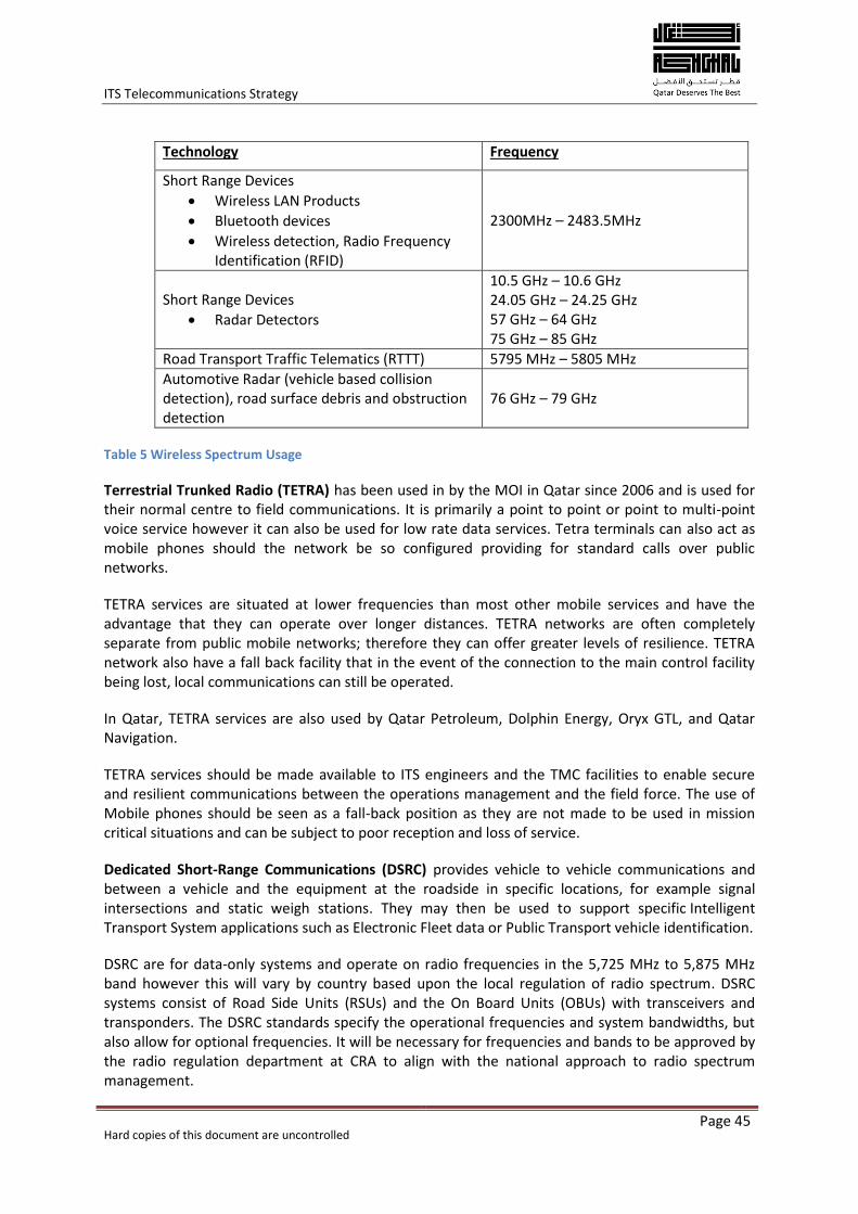
ITS Telecommunications Strategy
Hard copies of this document are uncontrolled
Page 45
Technology Frequency
Short Range Devices
Wireless LAN Products
Bluetooth devices
Wireless detection, Radio Frequency Identification (RFID)
2300MHz – 2483.5MHz
Short Range Devices
Radar Detectors
10.5 GHz – 10.6 GHz 24.05 GHz – 24.25 GHz 57 GHz – 64 GHz 75 GHz – 85 GHz
Road Transport Traffic Telematics (RTTT) 5795 MHz – 5805 MHz
Automotive Radar (vehicle based collision detection), road surface debris and obstruction detection
76 GHz – 79 GHz
Table 5 Wireless Spectrum Usage
Terrestrial Trunked Radio (TETRA) has been used in by the MOI in Qatar since 2006 and is used for their normal centre to field communications. It is primarily a point to point or point to multi-point voice service however it can also be used for low rate data services. Tetra terminals can also act as mobile phones should the network be so configured providing for standard calls over public networks.
TETRA services are situated at lower frequencies than most other mobile services and have the advantage that they can operate over longer distances. TETRA networks are often completely separate from public mobile networks; therefore they can offer greater levels of resilience. TETRA network also have a fall back facility that in the event of the connection to the main control facility being lost, local communications can still be operated.
In Qatar, TETRA services are also used by Qatar Petroleum, Dolphin Energy, Oryx GTL, and Qatar Navigation.
TETRA services should be made available to ITS engineers and the TMC facilities to enable secure and resilient communications between the operations management and the field force. The use of Mobile phones should be seen as a fall-back position as they are not made to be used in mission critical situations and can be subject to poor reception and loss of service.
Dedicated Short-Range Communications (DSRC) provides vehicle to vehicle communications and between a vehicle and the equipment at the roadside in specific locations, for example signal intersections and static weigh stations. They may then be used to support specific Intelligent Transport System applications such as Electronic Fleet data or Public Transport vehicle identification.
DSRC are for data-only systems and operate on radio frequencies in the 5,725 MHz to 5,875 MHz band however this will vary by country based upon the local regulation of radio spectrum. DSRC systems consist of Road Side Units (RSUs) and the On Board Units (OBUs) with transceivers and transponders. The DSRC standards specify the operational frequencies and system bandwidths, but also allow for optional frequencies. It will be necessary for frequencies and bands to be approved by the radio regulation department at CRA to align with the national approach to radio spectrum management.
ITS Telecommunications Strategy
Hard copies of this document are uncontrolled
Page 46
Standardization is essential in order to ensure interoperability across the Gulf Cooperation Council (GCC) States, particularly for applications such as vehicle data collection, Freight management for which there will be a need for interoperability of systems. Standardization will also assist with the provision and promotion of additional services using DSRC, and help ensure compatibility and interoperability within a multi-vendor environment.
DSRC is planned to be used for (infrastructure) field to vehicle and vehicle to vehicle communications for applications such as freight management and vehicle tracking as well as Road User Charging and Tolling.
Bluetooth is an unlicensed short range wireless communications system. Initially developed for communications between mobile phones and computers, it has developed into an almost universal method for creating Personal Area Networks (PAN).
Bluetooth is a popular technology for connecting mobile phones to vehicles thus aiding drivers to use phones hands free whilst driving. It is the use of Bluetooth in cars that has allowed technology deployed at the roadside to use the Bluetooth “Signatures” to allow journey time measurement to be undertaken. Only the Media Access Control (MAC) address is used in the Bluetooth data collection thus guaranteeing driver anonymity and security.
Bluetooth is a low powered short-range product and is only suitable for specific ITS applications. It will not be used as a mainstream telecommunications technology and as such will not be included in the Telecommunications Deployment Plan.
Wi-Fi is a wireless communications protocol used to connect computing devices to other computers or networks. Standards for Wi-Fi are governed by the Institute of Electrical and Electronics Engineers' (IEEE) 802.11 standards to ensure international compatibility. Wi-Fi is generally used as a synonym for a Wireless Local Area Network (WLAN).
In ITS vehicle based applications, Wi-Fi, due the nature of its communications methods is really only suitable for stationary or very slow moving equipment. Vehicles parked outside properties, at service stations or street side can benefit from data communications using Wi-Fi for updating car based information (navigation systems, vehicle data or driver profiles) or for sharing vehicle data at service centres or inspection centres.
Wi-Fi is ideally suited to short distance access network applications. Examples include communications from backbone and main carriageway routes to ITS technology deployed along side streets and across busy intersections. Products are available from a number of sources and are suited to the applications and environments found in the ITS for the State of Qatar. Applications include Traffic Signals, Remote DMS, RWIS and CCTV.
Worldwide Interoperability for Microwave Access (WiMax) is a form of wireless used for “Last Mile” communications where cable is not feasible due to cost or time to install. It is covered by the IEEE 802.16 standards. The average cell range of a WiMax device can actually be as much as 10-12 km for non-Line of Sight applications; 40km can be achieved with Line of Sight applications. Like all radio systems, distance will also affect the available bandwidth and Quality of Service (QoS) however bandwidth of 30-40Mbps can generally be achieved. WiMax is suited to remote applications that require longer distance wireless communications. It can also be used for building to building communications. Applications specific to ITS include remote CCTV, Remote DMS and RWIS.
Satellite Services are now available to Stakeholders and service providers in the State of Qatar following the launch in 2013 of the first Qatari owned satellite service, Es’hailSat. The
ITS Telecommunications Strategy
Hard copies of this document are uncontrolled
Page 47
telecommunications satellite is geostationary over the Gulf region and is capable of broadcast services as well as telecommunications services. Once in service, the satellite will be able to offer network connection facilities to remote parts of the state where normal telecommunications infrastructure is not available.
Mobile telephony Third Generation (3G) mobile telephone services, also known as Universal Mobile Telecommunications System (UMTS) have been operating in Qatar since 2006 and are operated by Ooredoo and Vodafone. As well as voice and video services, 3G/UMTS services also offer the opportunity for high rate data services. These data services will however be limited by local network capacity and network usage with city centre areas and business districts accounting for the greater proportion of network traffic. Network capacity is greater in the more remote areas on the outskirts of cities. Data speeds of 1 Mbps upload and 7.2 Mbps download have been available on the Ooredoo network since 2009.
3G mobile services also include General Packet Radio Service (GPRS) as part of the technology offering. GPRS is a data service however it is a “best effort” service which has variable data throughput and can suffer from issue with latency as it is a shard service. GPRS services do support Internet Protocols (IP) and can offer point to point or point to multipoint services. The cost and availability of GPRS services will vary with the service provider however they can offer remote connections to equipment off of a fixed line network e.g. DMS or weather alert systems.
3G data and GPRS technology is used for Machine to Machine (M2M) communications for remote equipment such as Remote DMS and RWIS. It is not suitable for safety critical systems such as Automated Incident detection as it works as a “best effort” principle through the public telecoms network rather than a private network.
Fourth Generation (4G) services, also known as Long Term Evolution (LTE) are starting to be rolled out across telecommunications networks however these have yet to be provided for public use in Qatar.
4G networks are different to previous mobile telephony services in that they are entirely IP based communications giving rise to enhanced data management and service improvements over 3G services.
In Qatar, the Ministry of the Interior (MOI) now operates a private 4G network for the MOI staff and related agencies, giving them the capability to transmit pictures and data to the National Command Centre (NCC) and to other MOI departments. The MOI intend to operate their 4G network in parallel with their existing Terrestrial Trunked Radio (TETRA) service.
Ooredoo and Vodafone are currently offering 4G services; the service coverage will develop across Doha with excellent signal strength in city areas however outside the city coverage is likely to be weak or non-existent.
4G networks can be used from either public or private operators and as such, the services using the 4G need to be appropriately segregated. Services using a public 4G network should be restricted to low priority, non-safety related services. Operational telephony and data services can use a private 4G network as long as the service levels are agreed beforehand. In the case of using the MOI 4G network, it needs to be recognised that in the event of a security crisis or high profile event, the MOI may, at very short notice, severely restrict access to the network, protecting the usage for their own operations.
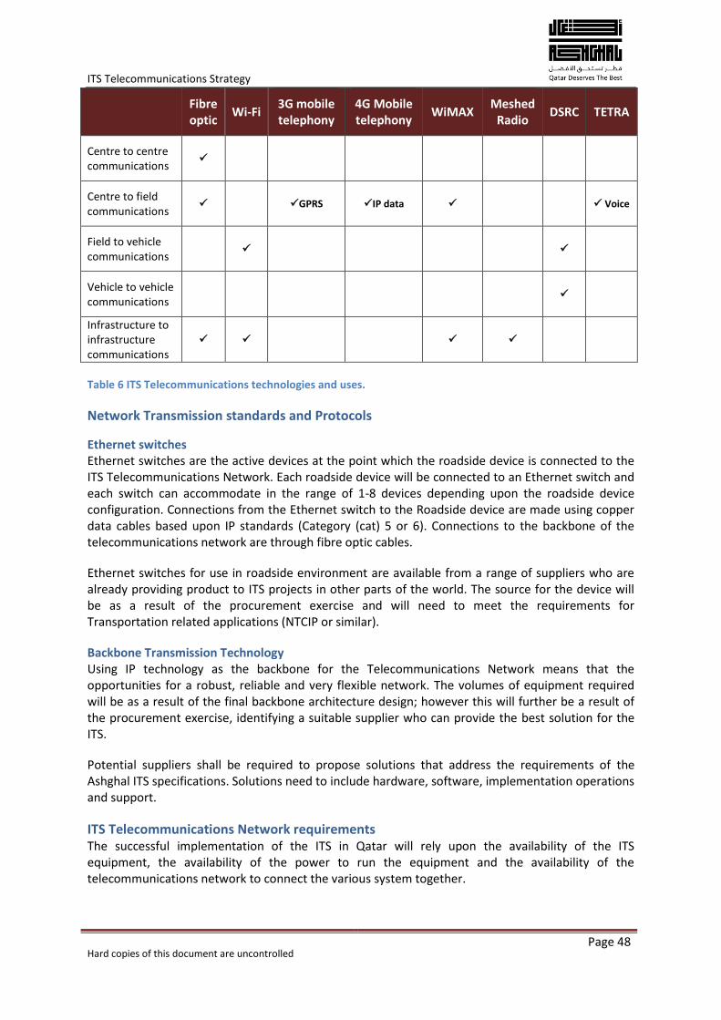
ITS Telecommunications Strategy
Hard copies of this document are uncontrolled
Page 48
Fibre optic
Wi-Fi 3G mobile telephony
4G Mobile telephony
WiMAX Meshed
Radio DSRC TETRA
Centre to centre communications
Centre to field communications
GPRS IP data Voice
Field to vehicle communications
Vehicle to vehicle communications
Infrastructure to infrastructure communications
Table 6 ITS Telecommunications technologies and uses.
Network Transmission standards and Protocols
Ethernet switches Ethernet switches are the active devices at the point which the roadside device is connected to the ITS Telecommunications Network. Each roadside device will be connected to an Ethernet switch and each switch can accommodate in the range of 1-8 devices depending upon the roadside device configuration. Connections from the Ethernet switch to the Roadside device are made using copper data cables based upon IP standards (Category (cat) 5 or 6). Connections to the backbone of the telecommunications network are through fibre optic cables.
Ethernet switches for use in roadside environment are available from a range of suppliers who are already providing product to ITS projects in other parts of the world. The source for the device will be as a result of the procurement exercise and will need to meet the requirements for Transportation related applications (NTCIP or similar).
Backbone Transmission Technology Using IP technology as the backbone for the Telecommunications Network means that the opportunities for a robust, reliable and very flexible network. The volumes of equipment required will be as a result of the final backbone architecture design; however this will further be a result of the procurement exercise, identifying a suitable supplier who can provide the best solution for the ITS.
Potential suppliers shall be required to propose solutions that address the requirements of the Ashghal ITS specifications. Solutions need to include hardware, software, implementation operations and support.
ITS Telecommunications Network requirements The successful implementation of the ITS in Qatar will rely upon the availability of the ITS equipment, the availability of the power to run the equipment and the availability of the telecommunications network to connect the various system together.
ITS Telecommunications Strategy
Hard copies of this document are uncontrolled
Page 49
The telecommunications network for the multi-modal ITS in Qatar is designed to be a Wide Area Network (WAN) topology, connecting the roadside equipment back to the TMC and to connect the TMC to other transportation Stakeholders and information providers. Existing WAN connectivity technologies available for use in the ITS Telecommunications Network are either fixed line or wireless.
Digital Communications The ITS Telecommunications Network will utilise digital communications where the common entry point to the network is through an Ethernet interface which is now being developed as the common form of network throughout the ITS industry.
The topology of the IP Network follows the same design as that of the public Internet, using a combination of access devices, backbone routers and high-speed data links to interconnect a large number of devices in a meshed configuration for high resilience.
The telecommunications network needs need to align with the business needs. The Ashghal strapline is “Qatar deserves the best” and the implementation of the telecommunications network must reflect this:
The network must be flexible, secure and resilient and deliver high availability.
Must facilitate cross organisation collaboration, not just in Ashghal but across the Government agencies for the State of Qatar
Must be cost effective and dimensioned to a size suitable for the task.
Will allow for the development and deployment of future services and applications.
These guiding principles initially look at the technical aspects that will underpin the telecommunications networks. These will need to be further supported by institutional and operational processes and strategies.
Network availability The network availability has been measured for a long time within the telecommunication industry. The term availability can be defined by:
The ability of a functional unit to be in a state to perform a required function under given conditions at a given instant of time or over a given time interval, assuming that the required external resources are provided (ISO2382-14).
In the case of the ITS for the State of Qatar, the external resources referred to above will be the power supply and the ITS Roadside equipment. Availability is often given as a percentage of time that the network is actually delivering services divided by the amount of time it is expected to be delivering service. The time the network is not delivering service is referred to as down time.
High quality core telecommunications services are typically quoted as having 99.999% (five-nines) availability. This figure typically excludes planned outages for network changes or expansion. The availability is an average over time and tells nothing about how frequently an outage may occur. If the system fails only once a year, the five-nines availability implies that it must be fixed in about five minutes. If it fails once a week, the time to restore services must be about six seconds. This can have significant detrimental impacts on traffic management outcomes. Guaranteed availability is achieved through designing, building and operating a network that is resilient, secure, flexible and reliable.
ITS Telecommunications Strategy
Hard copies of this document are uncontrolled
Page 50
Resilience A resilient network is a function of network infrastructure resilience which is primarily based on redundant network sections which are fault-tolerant, self-healing and which can manage congestion.
Telecommunication-quality networks require at least one redundant route, but this will be dependent on how much risk is tolerated. Where the time-to-repair an outage may be significant, then two levels of redundancy will be required.
To be effectively redundant, different paths must be geographically separate. Duplicating optical fibre cables down both sides of an expressway will meet this requirement if the threat is purely local, such as damage from local utility works. If, however, the threat is over a wide area, such as from an earthquake or flood, then significant assets can be affected over an entire city or region and significantly more effort will be required to achieve redundancy.
The resilience of a telecommunications network is the result of both technical and institutional solutions being in place. In conventional telecommunication networks, critical higher bandwidth portions of the network are duplicated to enable re-routing of data in the event of a network failure. It is generally the access element (the “last mile”) connection that is the weakest link so it is therefore in the best interest of the ITS to keep the access element as short as possible.
Technical solutions for telecommunications resilience must be supported by operational and organisational solutions and processes. In the event of a TMC facility failing and being evacuated, a technical solution i.e. a second (back-up) TMC site will need to be supported and the staff will need to be familiar with procedures for evacuation and relocation.
The introduction of pro-active maintenance regimes along with strategic spares holding and material management will also contribute to improved resilience and high network availability.
Security Security of telecommunications networks can provided in both physical and virtual forms. The standards and procedures for the implementation and operation of the networks will provide the physical security through ensuring that the infrastructure is built and maintained to the correct standards.
Ethernet technology will provide not only excellent performance for ITS services and applications, but a wide range of network security measures to maintain availability, integrity, and confidentiality of the ITS. Availability is very often mentioned as the main security requirement from an ITS point of view. Integrity protects data and systems from intentional or accidental alteration. Confidentiality helps ensure that data cannot be accessed by unauthorized users. These network security advantages protect roadside and network devices such as equipment controllers as well as TMC equipment, and apply to both physical equipment and data security practices.
As with any system characteristic, security is maintained through a lifecycle of design, implementation, maintenance, and improvement. Security and administration policies are a key foundation for developing robust network security. A security policy should logically segment the devices and network in an ITS environment into groups, zones or corridors on which the policies can be applied. Once the security policy is defined, there are a number of key technical capabilities available to implement the policy. These include, but are not limited to:
Access control and authentication
Secure connectivity and management
Firewalls
ITS Telecommunications Strategy
Hard copies of this document are uncontrolled
Page 51
Network Buffer zones
Load Balancing
VLAN configuration.
Operation of the network must be carried out in an appropriate manner in order that the security of the information is not compromised. This will require stringent controls in the management of software and network connections to ensure that the telecommunications network is suitable isolated from outside influences and interference.
Flexibility Flexibility in the telecommunications network will allow for as many services as possible to be accommodated over the network without increasing the complexity of the technologies involved. Whilst it will not be possible to accommodate all technologies, the correct design of the network and the correct selection of the technologies to be deployed will ensure viable levels of flexibility.
The use of Fibre optic technology and Ethernet and IP based services will provide the highest levels of flexibility that are available with the current forms of technology. Equipment manufacturers and network providers now use common, open standards and have moved away from bespoke solutions. It is through the application of open standards and applications that the maximum flexibility will be achieved.
Reliability Network reliability is important for the operational ITS services to ensure that the telecommunications network is available as and when it is required. Reliability is achieved in normal operation using a combination of high integrity equipment and a physical network designed to offer fall back services in the event of a network interruption. Fast fault recovery times are also important to resume normal service following an event or incident.
Because the ITS operates in real time, the telecommunications network must be available to users at the TMC on a continuous basis, with little or no downtime. Network reliability can be improved by using effective network design principles, as well as intelligent networking services.
Reliability needs to be considered at each stage of the telecommunications network. Especially important for network design considerations is the telecommunications network transmission equipment. At each point on the network, a number of techniques or considerations can be applied to achieve the required level of reliability:
At the roadside – Dual power supplies where required, ruggedised equipment and
professional installation methods
In the telecommunications network – Redundant network connections and links as well as
redundant or back-up TMC facilities. The use of Internet Protocol IP routing will ensure any
data being transmitted will find the best route between the end devices.
Bandwidth Each device connected to the network will require its own amount of bandwidth in order to communicate with other devices, systems or control facilities. Devices will range from low bandwidth devices such as message signs and signals through to high bandwidth devices such as CCTV systems and inter centre communications systems for management control centres.
It is therefore essential that the network has the flexibility to enable technology of various bandwidths to be deployed. Ethernet and IP based applications are the most suitable services that
ITS Telecommunications Strategy
Hard copies of this document are uncontrolled
Page 52
can provide suitable levels of bandwidth for ITS applications. The use of a common infrastructure will ensure consistent levels of bandwidth being available across the entire telecommunications network.
Latency Signals from field devices to other field devices or control centres will be used to trigger or initiate other processes or systems. It is essential that any delay for signals to complete the circuit route are managed and that the latency (delay) is kept to a minimum.
Ethernet technologies used in ITS networks normally have very low latencies, which refers to the time it takes for a network packet to transit between a roadside device and the TMC. Most ITS operations and applications can tolerate latencies of 10 to 50 milliseconds (ms) with some older traffic signal control systems capable of tolerating 500ms delay. Because Ethernet applications for ITS are of low capacity (a few hundred bytes), the latency introduced by an Ethernet switch at 100 Mbps is only about 30 microseconds with a worst-case scenario of close to 100 microseconds—well below the limit and 100 times faster than most applications require.
Latency on public or third party networks is more difficult to manage or predict and can result in system or service instability. Third party operators will need occasionally to undertake network load balancing activities and will re-route traffic as a result of repairs or service interruptions. Automatic or unplanned changes in the routing of circuits will introduce additional delay that is unforeseen and can cause some systems to become unstable or fail. Whilst it is possible to have Service Level Agreements in place to agree set parameters for network performance, the increasingly autonomous nature of telecommunications networks means that on occasions that will re-arrange themselves without notice, changing latency values and un-balancing some of the network systems.
ITS Telecommunications Strategy
Hard copies of this document are uncontrolled
Page 53
Appendix D. Drawings for the ITS telecommunications Network
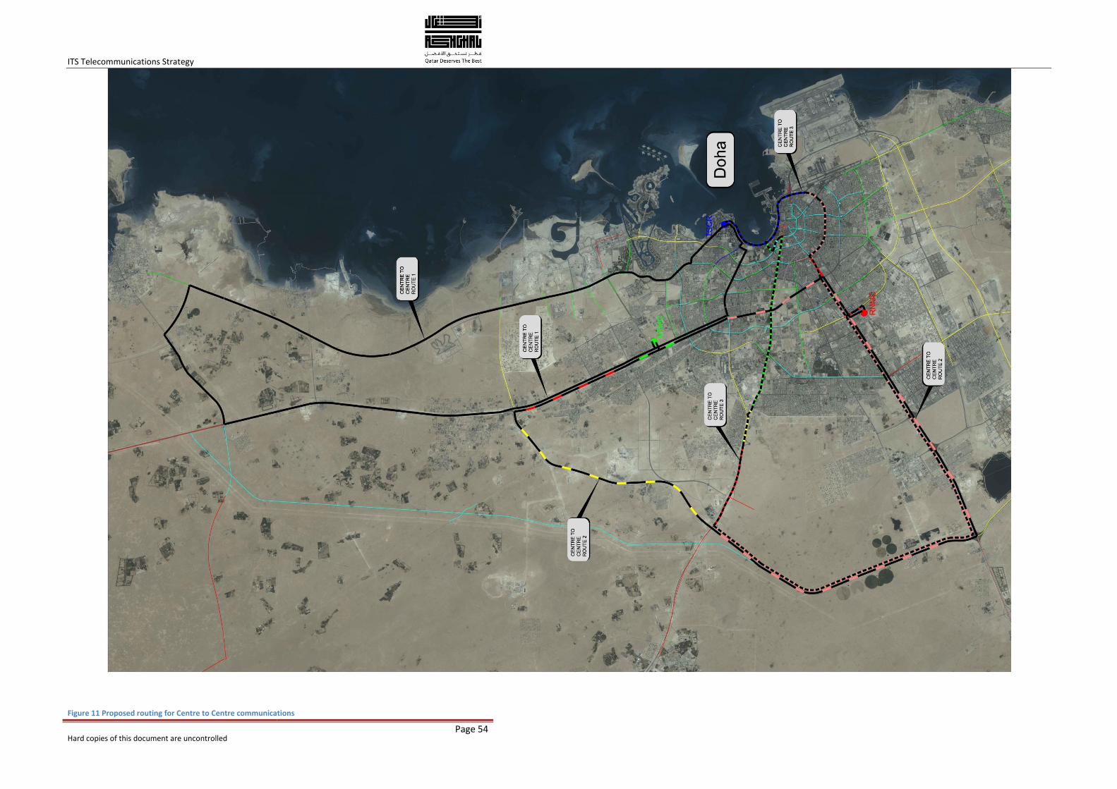
ITS Telecommunications Strategy
Hard copies of this document are uncontrolled
Page 54
Figure 11 Proposed routing for Centre to Centre communications
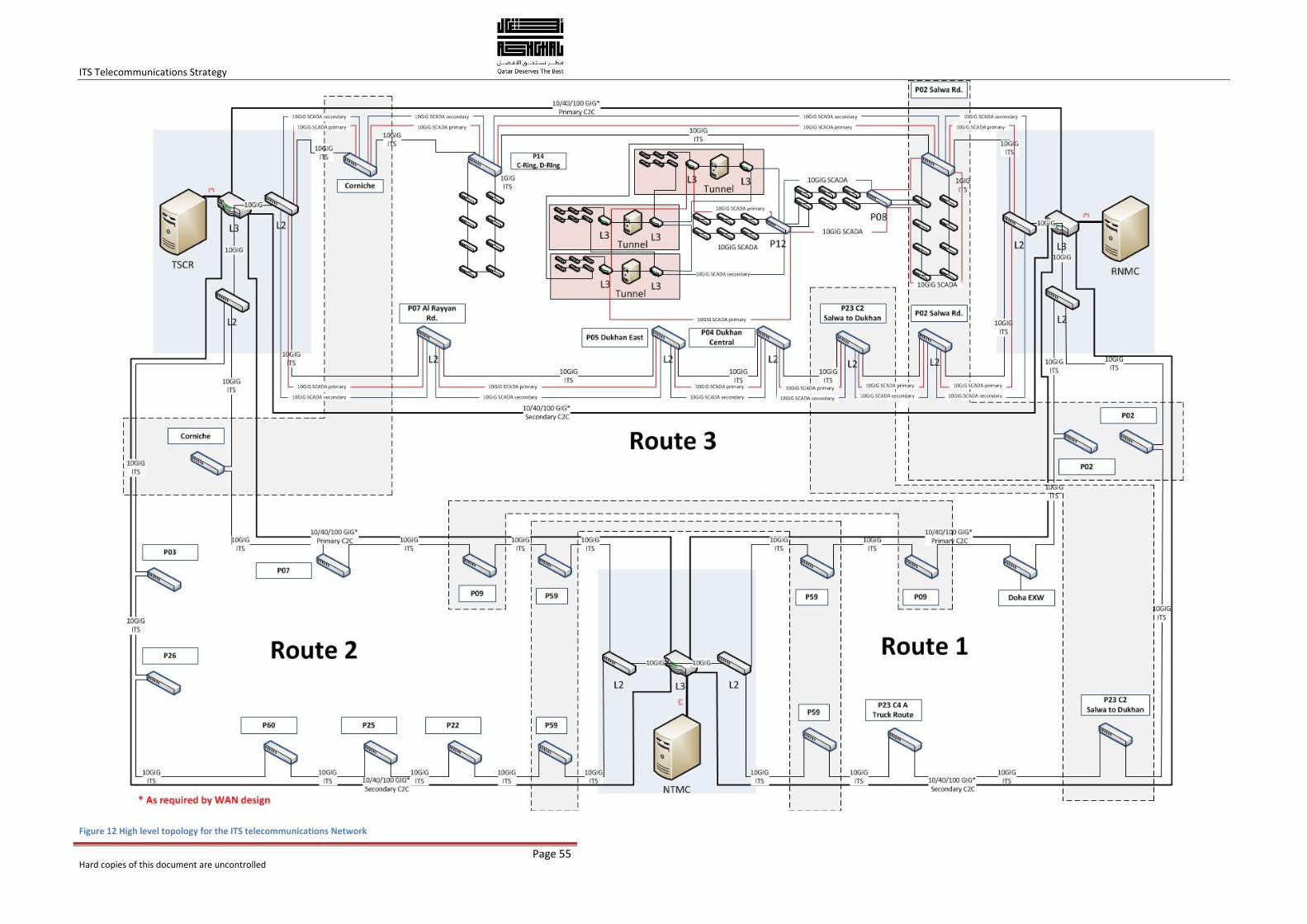
ITS Telecommunications Strategy
Hard copies of this document are uncontrolled
Page 55
Figure 12 High level topology for the ITS telecommunications Network
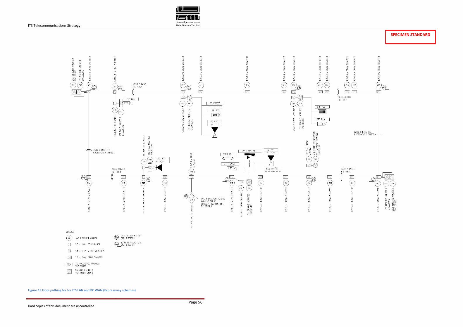
ITS Telecommunications Strategy
Hard copies of this document are uncontrolled
Page 56
Figure 13 Fibre pathing for for ITS LAN and PC WAN (Expressway schemes)
SPECIMEN STANDARD
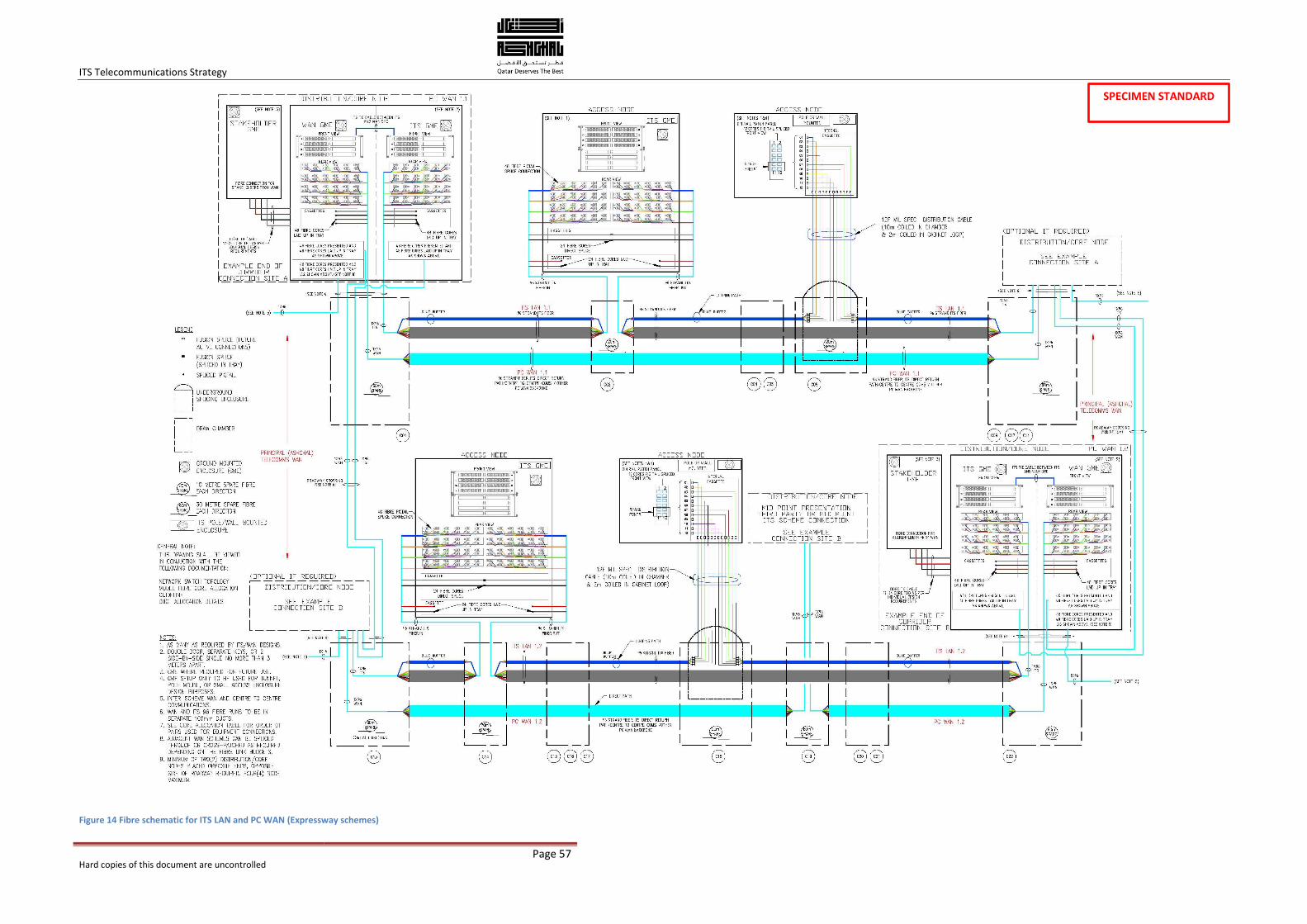
ITS Telecommunications Strategy
Hard copies of this document are uncontrolled
Page 57
Figure 14 Fibre schematic for ITS LAN and PC WAN (Expressway schemes)
SPECIMEN STANDARD
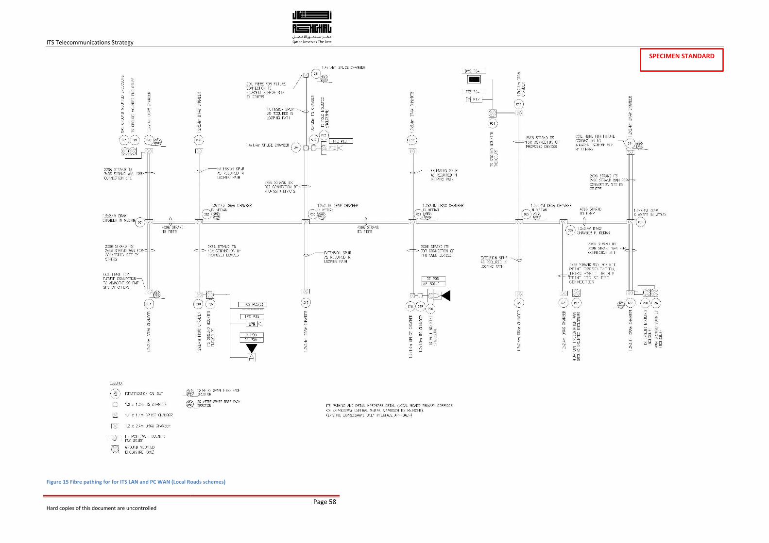
ITS Telecommunications Strategy
Hard copies of this document are uncontrolled
Page 58
Figure 15 Fibre pathing for for ITS LAN and PC WAN (Local Roads schemes)
SPECIMEN STANDARD
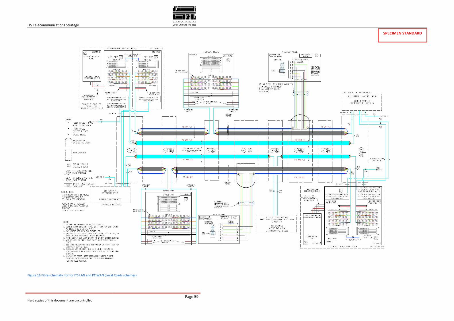
ITS Telecommunications Strategy
Hard copies of this document are uncontrolled
Page 59
Figure 16 Fibre schematic for for ITS LAN and PC WAN (Local Roads schemes)
SPECIMEN STANDARD
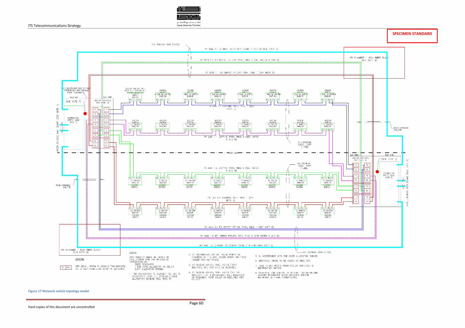
ITS Telecommunications Strategy
Hard copies of this document are uncontrolled
Page 60
Figure 17 Network switch topology model
SPECIMEN STANDARD
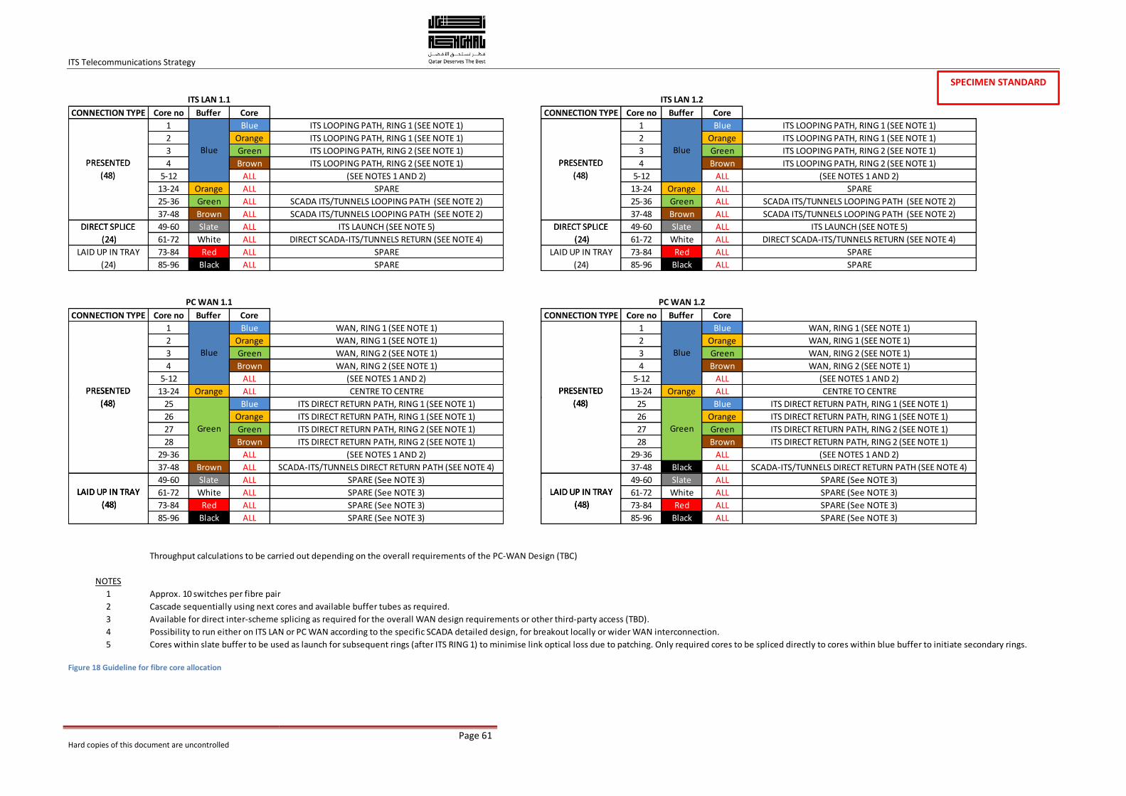
ITS Telecommunications Strategy
Hard copies of this document are uncontrolled
Page 61
Figure 18 Guideline for fibre core allocation
CONNECTION TYPE Core no Buffer Core CONNECTION TYPE Core no Buffer Core
ITS LAN 1.1 ITS LAN 1.2
PRESENTED
(48)
PRESENTED
(48)
Blue Blue
1 Blue ITS LOOPING PATH, RING 1 (SEE NOTE 1) 1 Blue ITS LOOPING PATH, RING 1 (SEE NOTE 1)
2 Orange ITS LOOPING PATH, RING 1 (SEE NOTE 1) 2 Orange ITS LOOPING PATH, RING 1 (SEE NOTE 1)
3 Green ITS LOOPING PATH, RING 2 (SEE NOTE 1) 3 Green ITS LOOPING PATH, RING 2 (SEE NOTE 1)
4 Brown ITS LOOPING PATH, RING 2 (SEE NOTE 1) 4 Brown ITS LOOPING PATH, RING 2 (SEE NOTE 1)
5-12 ALL (SEE NOTES 1 AND 2) 5-12 ALL (SEE NOTES 1 AND 2)
13-24 Orange ALL SPARE 13-24 Orange ALL SPARE
25-36 Green ALL SCADA ITS/TUNNELS LOOPING PATH (SEE NOTE 2) 25-36 Green ALL SCADA ITS/TUNNELS LOOPING PATH (SEE NOTE 2)
37-48 Brown ALL SCADA ITS/TUNNELS LOOPING PATH (SEE NOTE 2) 37-48 Brown ALL SCADA ITS/TUNNELS LOOPING PATH (SEE NOTE 2)
PRESENTED
(48)
DIRECT SPLICE
(24)
PRESENTED
(48)
DIRECT SPLICE
(24)
Blue Blue
49-60 Slate ALL ITS LAUNCH (SEE NOTE 5) 49-60 Slate ALL ITS LAUNCH (SEE NOTE 5)
61-72 White ALL DIRECT SCADA-ITS/TUNNELS RETURN (SEE NOTE 4) 61-72 White ALL DIRECT SCADA-ITS/TUNNELS RETURN (SEE NOTE 4)
73-84 Red ALL SPARE 73-84 Red ALL SPARE
85-96 Black ALL SPARE 85-96 Black ALL SPARE
CONNECTION TYPE Core no Buffer Core CONNECTION TYPE Core no Buffer Core
PRESENTED
(48)
PRESENTED
(48)
Blue Blue
PC WAN 1.1 PC WAN 1.2
LAID UP IN TRAY
(24)
DIRECT SPLICE
(24)
DIRECT SPLICE
(24)
LAID UP IN TRAY
(24)
1 Blue WAN, RING 1 (SEE NOTE 1) 1 Blue WAN, RING 1 (SEE NOTE 1)
2 Orange WAN, RING 1 (SEE NOTE 1) 2 Orange WAN, RING 1 (SEE NOTE 1)
3 Green WAN, RING 2 (SEE NOTE 1) 3 Green WAN, RING 2 (SEE NOTE 1)
4 Brown WAN, RING 2 (SEE NOTE 1) 4 Brown WAN, RING 2 (SEE NOTE 1)
5-12 ALL (SEE NOTES 1 AND 2) 5-12 ALL (SEE NOTES 1 AND 2)
13-24 Orange ALL CENTRE TO CENTRE 13-24 Orange ALL CENTRE TO CENTRE
Green
PRESENTED
(48)
PRESENTED
(48)
Blue
Green
Blue
25 Blue ITS DIRECT RETURN PATH, RING 1 (SEE NOTE 1) 25 Blue ITS DIRECT RETURN PATH, RING 1 (SEE NOTE 1)
26 Orange ITS DIRECT RETURN PATH, RING 1 (SEE NOTE 1) 26 Orange ITS DIRECT RETURN PATH, RING 1 (SEE NOTE 1)
27 Green ITS DIRECT RETURN PATH, RING 2 (SEE NOTE 1) 27 Green ITS DIRECT RETURN PATH, RING 2 (SEE NOTE 1)
28 Brown ITS DIRECT RETURN PATH, RING 2 (SEE NOTE 1) 28 Brown ITS DIRECT RETURN PATH, RING 2 (SEE NOTE 1)
29-36 ALL (SEE NOTES 1 AND 2) 29-36 ALL (SEE NOTES 1 AND 2)
37-48 Brown ALL SCADA-ITS/TUNNELS DIRECT RETURN PATH (SEE NOTE 4) 37-48 Black ALL SCADA-ITS/TUNNELS DIRECT RETURN PATH (SEE NOTE 4)
Green
PRESENTED
(48)
PRESENTED
(48)
LAID UP IN TRAY
(48)
LAID UP IN TRAY
(48)
Green
49-60 Slate ALL SPARE (See NOTE 3) 49-60 Slate ALL SPARE (See NOTE 3)
61-72 White ALL SPARE (See NOTE 3) 61-72 White ALL SPARE (See NOTE 3)LAID UP IN TRAY
(48)
LAID UP IN TRAY
(48)73-84 Red ALL SPARE (See NOTE 3) 73-84 Red ALL SPARE (See NOTE 3)
85-96 Black ALL SPARE (See NOTE 3) 85-96 Black ALL SPARE (See NOTE 3)
Throughput calculations to be carried out depending on the overall requirements of the PC-WAN Design (TBC)
NOTES
1 Approx. 10 switches per fibre pair
2 Cascade sequentially using next cores and available buffer tubes as required.
3 Available for direct inter-scheme splicing as required for the overall WAN design requirements or other third-party access (TBD).
4 Possibility to run either on ITS LAN or PC WAN according to the specific SCADA detailed design, for breakout locally or wider WAN interconnection.
5 Cores within slate buffer to be used as launch for subsequent rings (after ITS RING 1) to minimise link optical loss due to patching. Only required cores to be spliced directly to cores within blue buffer to initiate secondary rings.
LAID UP IN TRAY
(48)
LAID UP IN TRAY
(48)
SPECIMEN STANDARD
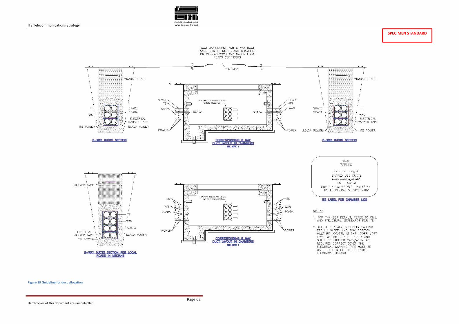
ITS Telecommunications Strategy
Hard copies of this document are uncontrolled
Page 62
Figure 19 Guideline for duct allocation
SPECIMEN STANDARD
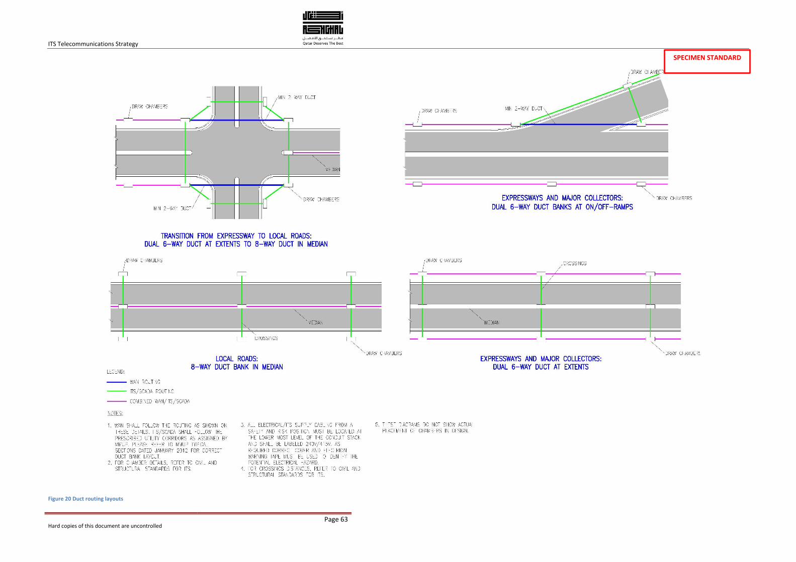
ITS Telecommunications Strategy
Hard copies of this document are uncontrolled
Page 63
Figure 20 Duct routing layouts
SPECIMEN STANDARD

Prepared by