Embed Size (px)
Citation preview

Intelligent Systems Lab.
Extrinsic Self Calibration of a Camera and a 3D Laser Range Finder from Natural Scenes
Davide Scaramuzza, Ahad Harati, and Roland Siegwar
IEEE/RSJ International Conference on Intelligent Robots and Systems, IROS, 2007
Presenter: Van-Dung [email protected]
October 12, 2013

Intelligent Systems Lab.2
Content
Introduction Camera and LRF model Bearing angle images Extrinsic laser-camera calibration Experiments Conclusions
Intelligent Systems Lab.3
Introduction
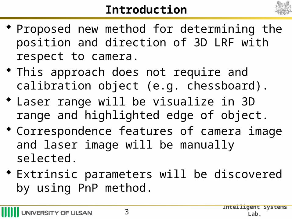
Proposed new method for determining the position and direction of 3D LRF with respect to camera.
This approach does not require and calibration object (e.g. chessboard).
Laser range will be visualize in 3D range and highlighted edge of object.
Correspondence features of camera image and laser image will be manually selected.
Extrinsic parameters will be discovered by using PnP method.

Intelligent Systems Lab.4
Camera model The camera system consists of
perspective camera, catadioptric mirror, which has a single center of projection.
Image point- 3D point estimate
(u,v) is point in image.
[x, y, z] is a ray from center of camera to point in world.
is scalar value.
F is a project function, it depend on the camera used.
Intelligent Systems Lab.5
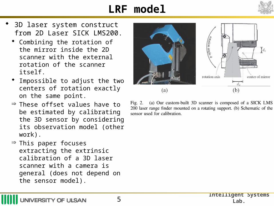
LRF model 3D laser system construct from 2D
Laser SICK LMS200. Combining the rotation of the mirror
inside the 2D scanner with the external rotation of the scanner itself.
Impossible to adjust the two centers of rotation exactly on the same point.
Þ These offset values have to be estimated by calibrating the 3D sensor by considering its observation model (other work).
Þ This paper focuses extracting the extrinsic calibration of a 3D laser scanner with a camera is general (does not depend on the sensor model).

Intelligent Systems Lab.6
LRF model The sensor model can be written:
where ρij is the j-th measured distance with orientation θj in the i-th scan line, and angle j (external rotation) with the horizontal plane.
(dx, dz) is offset of the external rotation axis from the center of the laser mirror.
Intelligent Systems Lab.7
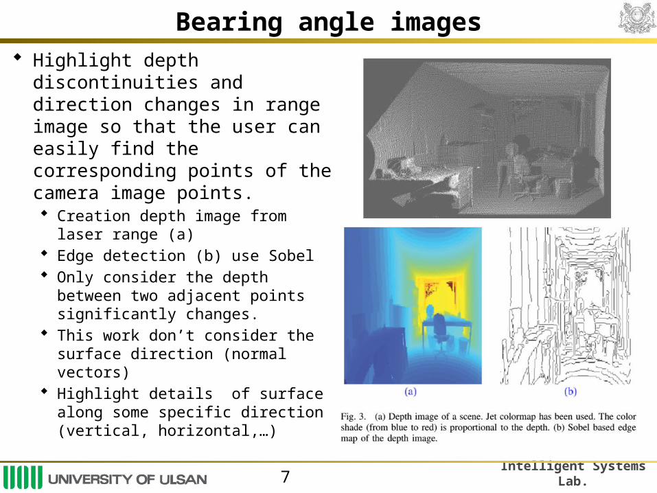
Bearing angle images Highlight depth discontinuities
and direction changes in range image so that the user can easily find the corresponding points of the camera image points. Creation depth image from laser
range (a) Edge detection (b) use Sobel Only consider the depth between
two adjacent points significantly changes.
This work don’t consider the surface direction (normal vectors)
Highlight details of surface along some specific direction (vertical, horizontal,…)

Intelligent Systems Lab.8
Bearing angle images
Bearing Angle (BA) the angle between the laser beam and the segment joining two consecutive measurement points (a)
Where ρi is the i- th depth value in the selected trace of the depth matrix and d is the corresponding angle increment.
Constructing BA image.

Intelligent Systems Lab.9
Bearing angle images
Pi
Pi-1
pi pi-1
d
iBA

Intelligent Systems Lab.10
Bearing angle images

Intelligent Systems Lab.11
Extrinsic laser-camera calibration
Data process: Collecting data and image. Computing BA images Manually select correspondence points between BA image and
intensity image. Store correspondence points
where θC and θL are unit norm orientation vectors of camera and laser points
dL is the point distances in laser frame.

Intelligent Systems Lab.12
Extrinsic laser-camera calibration
Extrinsic calibration Finding rotation R and translation T between Camera-LRF
+ To minimize error function
where (R, T, pi) is the reprojection onto the image plane
of the laser point pi, mi is correspondence image point with pi.
+ Due to camera resolution is not uniform, another criteria is used.
where θCL is the unit norm orientation vector of (R, T, pi)
Intelligent Systems Lab.13
Extrinsic laser-camera calibration
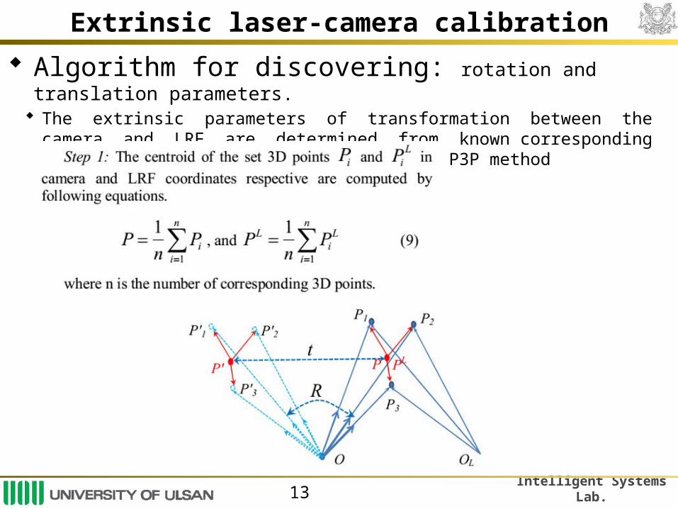
Algorithm for discovering: rotation and translation parameters. The extrinsic parameters of transformation between the camera and LRF are
determined from known corresponding 3D points. It is solved by using the P3P method
Intelligent Systems Lab.14
Extrinsic calibration extraction

Intelligent Systems Lab.15
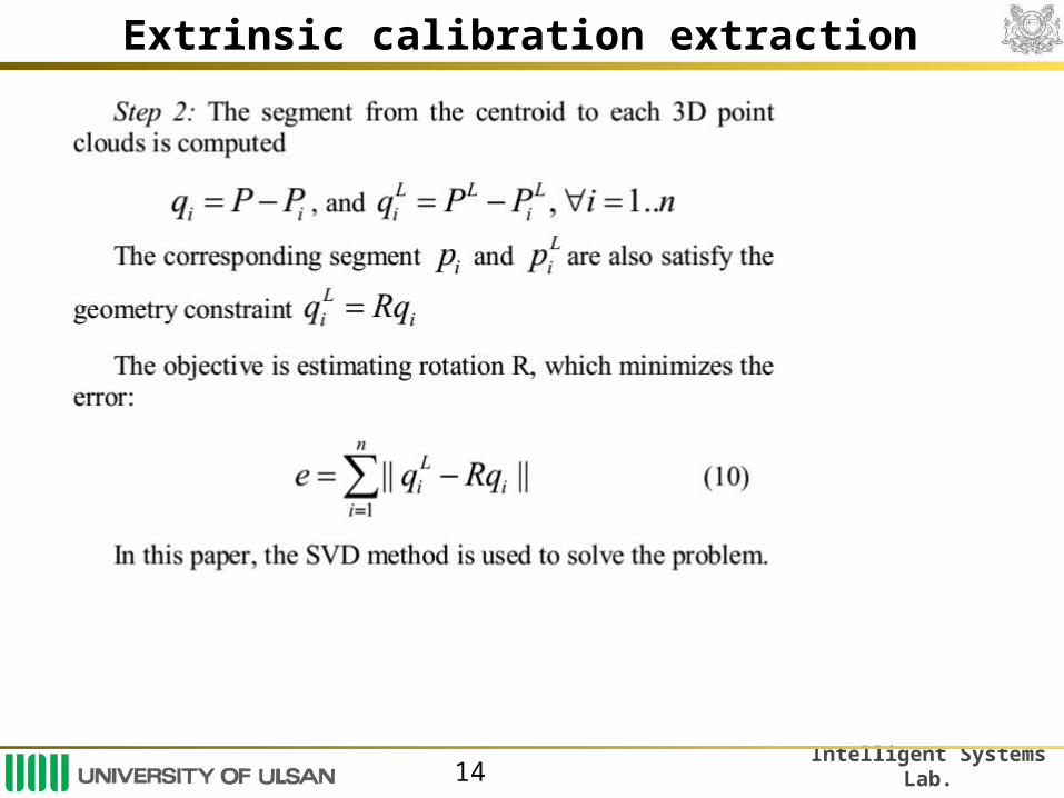
Extrinsic calibration extraction
The rotation matrix R =X if det(X)=1, otherwise for failure solution. Step 4: Translation:

Intelligent Systems Lab.16
Experimental results
Setup the system: Camera SONY XCD-SX910-CR Mirror: KAIDAN 360 One VR hyperbolic Laser SICK LMS 200.
FOV 180O, resolution 0.5O
Rotating scanner. FOV 360O, resolution 1O

Intelligent Systems Lab.17
Experimental results
Estimation of the translation (meters) versus the number of selected points.
Estimation of the rotation (roll, pitch, and yaw angles) versus the number of selected points (the x-axis ranges from 4 to 10).

Intelligent Systems Lab.18
Experimental results
Re-projection laser point onto intensity image

Intelligent Systems Lab.19
Experimental results
Construction 3D point cloud from laser points and vision points.

Intelligent Systems Lab.20
Conclusions The method uses only a few correspondent points that manually
selected by the user from natural scene. No calibration patterns are required, nor more than one single laser-
camera acquisition necessary. The proposed method relies on a novel technique to visualize the
range information obtained from a 3D laser scanner. The BA images and the application of the method to an omni camera
were the two main contributions of the paper. Proposed approach requires no special equipment and allows the
user to calibrate quickly the system.

Intelligent Systems Lab.
THANK YOU FOR ATTENTION!

Intelligent Systems Lab.22
Project function
This paper the camera coordinate system coincides with the single effective viewpoint.
The x-y plane is orthogonal to the mirror axis.
2 2 2
2 2 2
2 2 2
2 2 2
2 2 2
2 2 2
1 (1 )( )
1 (1 )( )( , )
1 (1 )( )
u vu
u v
u vF u v v
u v
u v
u v
The distance d between focal points of conic and the latus rectum l.

![Ahadun Ahad - Creative Motivationscreative-motivations.com/wp-content/uploads/2016/03/Ahadun-Ahad … · Al-Ahad [112:1] The One and Unique He is One, Unique, and He has no origin](https://img.pdfslide.us/doc/110x75/5f505ab66caef736d810fe1b/ahadun-ahad-creative-motivationscreative-al-ahad-1121-the-one-and-unique.jpg)