Embed Size (px)
Citation preview
INTELLIGENT MULTIPLEX SYSTEM
ISIS inlInk™ InStallatIon InStructIonS
dISconnectIng MaStercell™ unIt
Unplug all connections to the MASTERCELL™ input unit as shown in the diagram to the left.
Remove the input unit from your vehicle and proceed to step 2.
SteP 1
Screw reMoval
Turn over the MASTERCELL™ unit and remove the screws from the back of the input unit using a phillips screwdriver. There are two screws on each side of the box for a total of eight.
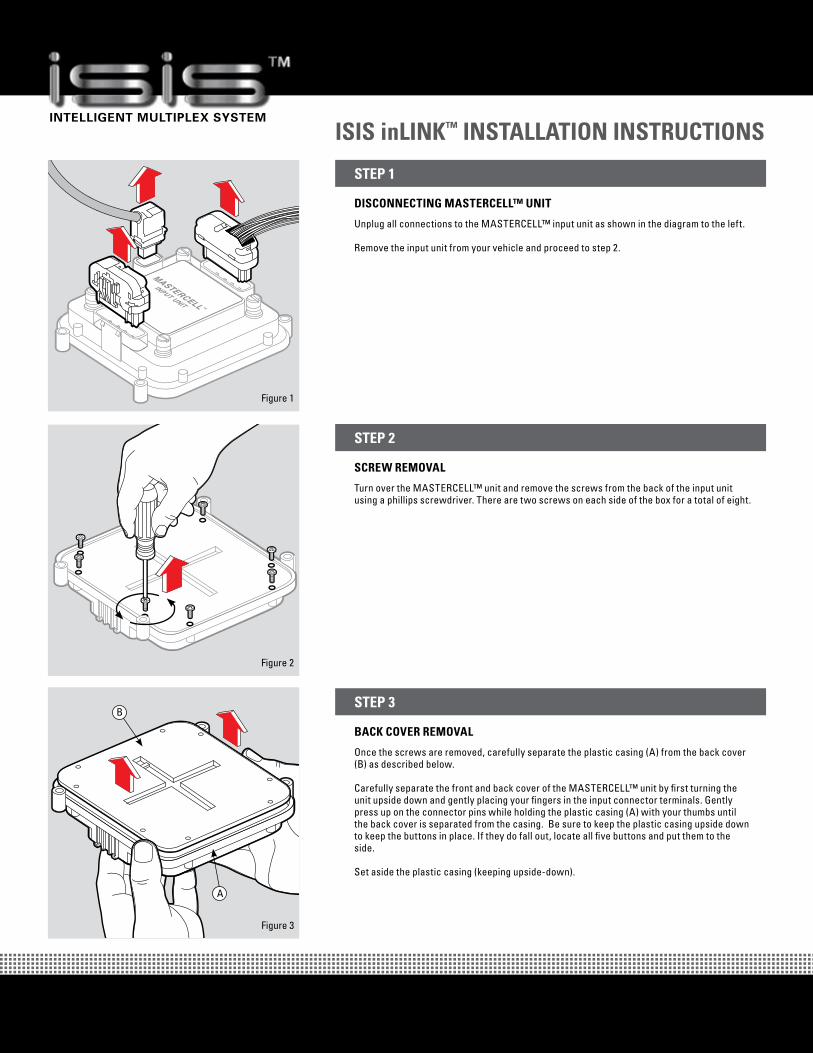
SteP 2
back cover reMoval
Once the screws are removed, carefully separate the plastic casing (A) from the back cover (B) as described below.
Carefully separate the front and back cover of the MASTERCELL™ unit by first turning the unit upside down and gently placing your fingers in the input connector terminals. Gently press up on the connector pins while holding the plastic casing (A) with your thumbs until the back cover is separated from the casing. Be sure to keep the plastic casing upside down to keep the buttons in place. If they do fall out, locate all five buttons and put them to the side.
Set aside the plastic casing (keeping upside-down).
SteP 3
Figure 1
Figure 2
Figure 3
B
A

INTELLIGENT MULTIPLEX SYSTEM
ISIS inlInk™ InStallatIon InStructIonS
radIo board InStallatIon PreParatIon
Disconnect the daughter board (A) in figure 4 from the top header (C) on the radio board (B). Be careful not to bend the pins when removing.
SteP 4
clear SPacer PlaceMent
Place the two clear spacers (A) on the board (B) as shown in figure 5 to the left.
SteP 5
radIo board InStallatIon
While keeping the spacers in place, carefully align the pins on the radio board (A) with the header on the MASTERCELL™ board labeled ISIS Radio Module (B) as shown in figure 6.
Insert the radio board pins (A) into the MASTERCELL™ unit connecting header (B) and push in the board until the plastic connector on the radio board meets with the header on the MASTERCELL™ board.
Ensure that the spacers are still aligned with the holes prior to securing the radio board with screws. If the spacers are not aligned, CAREFULLY put them back in place using a small tool.
SteP 6
Figure 4
Figure 5
Figure 6
B C
A
B
A
B
A
INTELLIGENT MULTIPLEX SYSTEM
ISIS inlInk™ InStallatIon InStructIonS
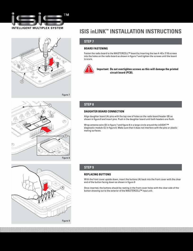
board faStenIng
Fasten the radio board to the MASTERCELL™ board by inserting the two 4-40 x 7/18 screws into the holes on the radio board as shown in figure 7 and tighten the screws until the board is scure.
Important: do not overtighten screws as this will damage the printed circuit board (Pcb).
SteP 7
daughter board connectIon
Align daughter board (A) pins with the top row of holes on the radio board header (B) as shown in figure 8 and insert pins. Push in the daughter board until both headers are flush.
Wrap antenna wire (D) in figure 7 and figure 8 in a large circle around the inSIGHT™ diagnostic module (C) in figure 8. Make sure that it does not interfere with the pins or plastic mating surfaces.
SteP 8
rePlacIng buttonS
With the front cover upside down, insert the buttons (A) back into the front cover with the clear end of the button facing down as shown in figure 9
Once inserted, the buttons should be resting in the front cover holes with the clear side of the button showing out to the exterior of the MASTERCELL™ input unit.
SteP 9
Figure 7
Figure 8
Figure 9
D
B
C
A
A
D
INTELLIGENT MULTIPLEX SYSTEM
ISIS inlInk™ InStallatIon InStructIonS
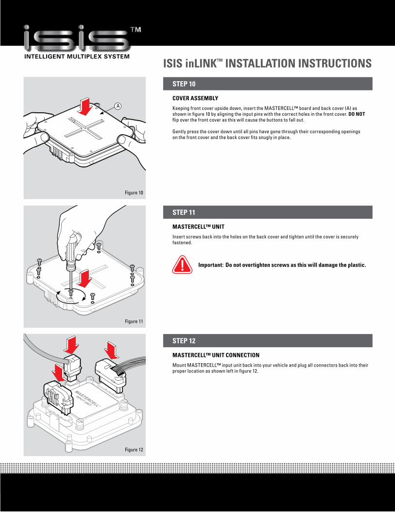
cover aSSeMbly
Keeping front cover upside down, insert the MASTERCELL™ board and back cover (A) as shown in figure 10 by aligning the input pins with the correct holes in the front cover. do not flip over the front cover as this will cause the buttons to fall out.
Gently press the cover down until all pins have gone through their corresponding openings on the front cover and the back cover fits snugly in place.
SteP 10
MaStercell™ unIt
Insert screws back into the holes on the back cover and tighten until the cover is securely fastened.
Important: do not overtighten screws as this will damage the plastic.
SteP 11
MaStercell™ unIt connectIon
Mount MASTERCELL™ input unit back into your vehicle and plug all connectors back into their proper location as shown left in figure 12.
SteP 12
Figure 10
Figure 11
Figure 12
A