Embed Size (px)
Citation preview
1© 2005 Cisco Systems, Inc. All rights reserved.Session NumberPresentation_ID Cisco Confidential
Intelligent Information Network
2© 2005 Cisco Systems, Inc. All rights reserved.Session NumberPresentation_ID Cisco Confidential
FTTX Deployment Considerations
Wolfgang [email protected]

3© 2005 Cisco Systems, Inc. All rights reserved.Session NumberPresentation_ID Cisco Confidential
Trends for access bitrates
333© 2003, Cisco Systems, Inc. All rights reserved.Presentation_ID
4© 2005 Cisco Systems, Inc. All rights reserved.Session NumberPresentation_ID Cisco Confidential
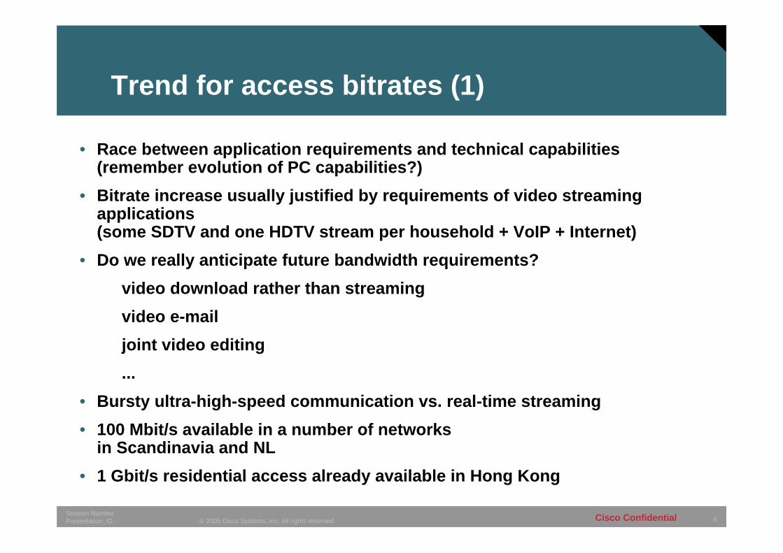
Trend for access bitrates (1)
• Race between application requirements and technical capabilities(remember evolution of PC capabilities?)
• Bitrate increase usually justified by requirements of video streaming applications (some SDTV and one HDTV stream per household + VoIP + Internet)
• Do we really anticipate future bandwidth requirements?video download rather than streamingvideo e-mailjoint video editing...
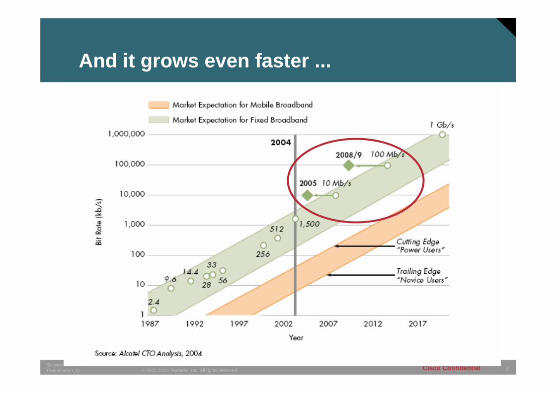
• Bursty ultra-high-speed communication vs. real-time streaming• 100 Mbit/s available in a number of networks
in Scandinavia and NL• 1 Gbit/s residential access already available in Hong Kong
5© 2005 Cisco Systems, Inc. All rights reserved.Session NumberPresentation_ID Cisco Confidential
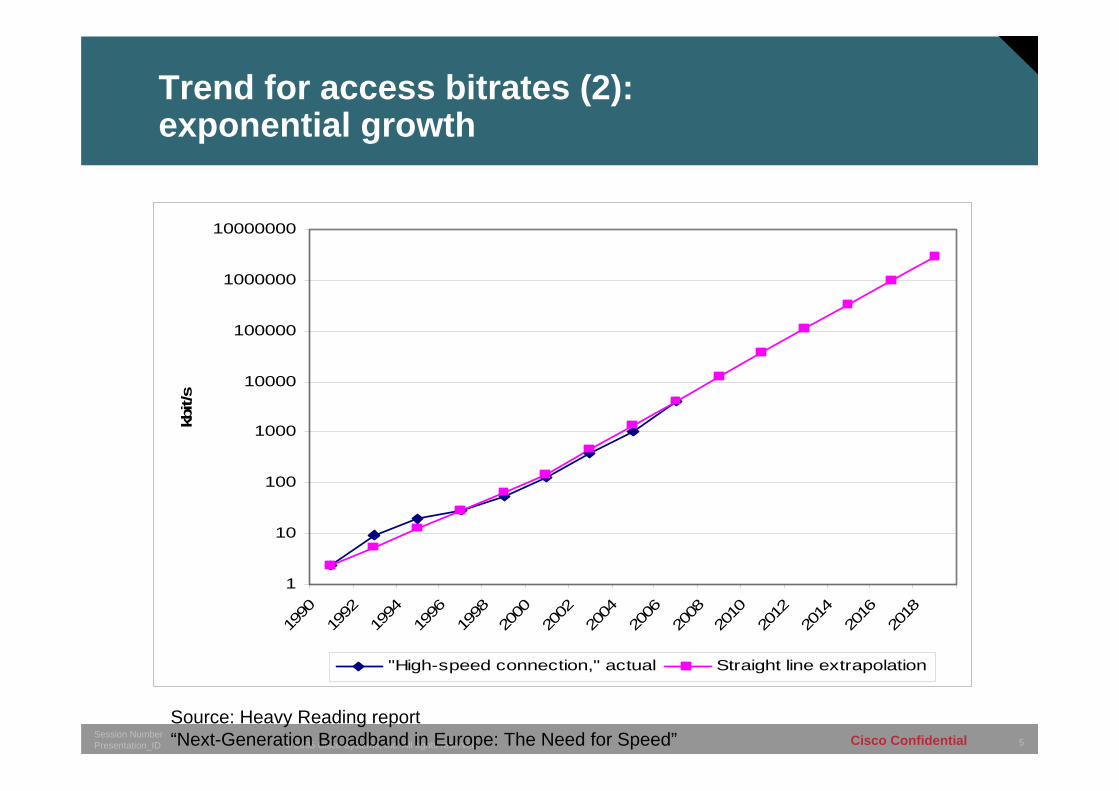
Trend for access bitrates (2):exponential growth
1
10
100
1000
10000
100000
1000000
10000000
1990
1992
1994
1996
1998
2000
2002
2004
2006
2008
2010
2012
2014
2016
2018
kbit/
s
"High-speed connection," actual Straight line extrapolation
Source: Heavy Reading report “Next-Generation Broadband in Europe: The Need for Speed”
6© 2005 Cisco Systems, Inc. All rights reserved.Session NumberPresentation_ID Cisco Confidential
And it grows even faster ...

7© 2005 Cisco Systems, Inc. All rights reserved.Session NumberPresentation_ID Cisco Confidential
Topologies
777© 2003, Cisco Systems, Inc. All rights reserved.Presentation_ID
8© 2005 Cisco Systems, Inc. All rights reserved.Session NumberPresentation_ID Cisco Confidential
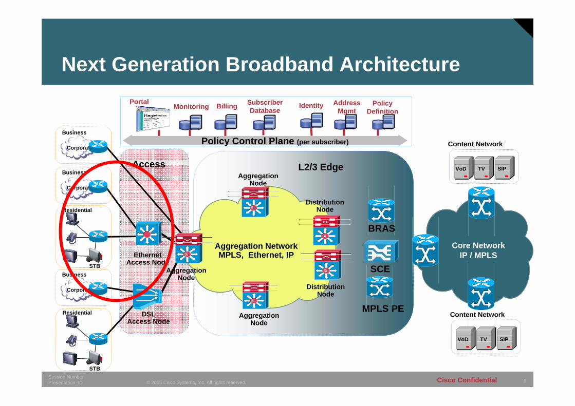
Next Generation Broadband Architecture
DSL Access Node
Distribution Node
BRAS
MPLS PE
SCE
Residential
STB
Aggregation Node
Aggregation Node
Core NetworkIP / MPLS
VoD
Content Network
TV SIPBusiness
Corporate
Business
Corporate
Aggregation Node
SiSi
SiSi
SiSi
SiSi
SiSi
Ethernet Access Node
Aggregation NetworkMPLS, Ethernet, IP
Distribution Node
Access L2/3 Edge
Identity Address Mgmt
Portal Subscriber DatabaseMonitoring Policy
DefinitionBilling
Policy Control Plane (per subscriber)
VoD
Content Network
TV SIP
Residential
STBBusiness
Corporate
9© 2005 Cisco Systems, Inc. All rights reserved.Session NumberPresentation_ID Cisco Confidential
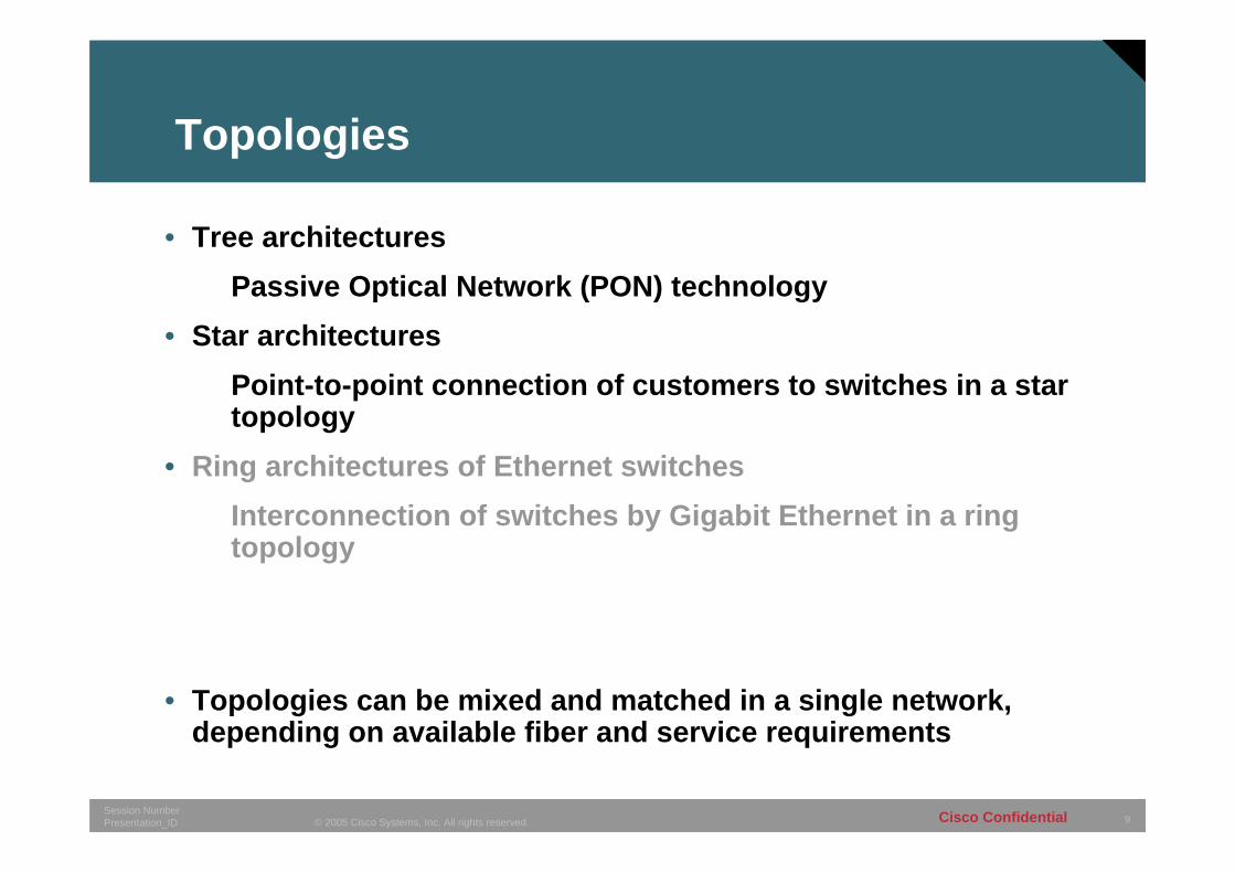
Topologies
• Tree architecturesPassive Optical Network (PON) technology
• Star architecturesPoint-to-point connection of customers to switches in a star topology
• Ring architectures of Ethernet switchesInterconnection of switches by Gigabit Ethernet in a ring topology
• Topologies can be mixed and matched in a single network, depending on available fiber and service requirements
10© 2005 Cisco Systems, Inc. All rights reserved.Session NumberPresentation_ID Cisco Confidential
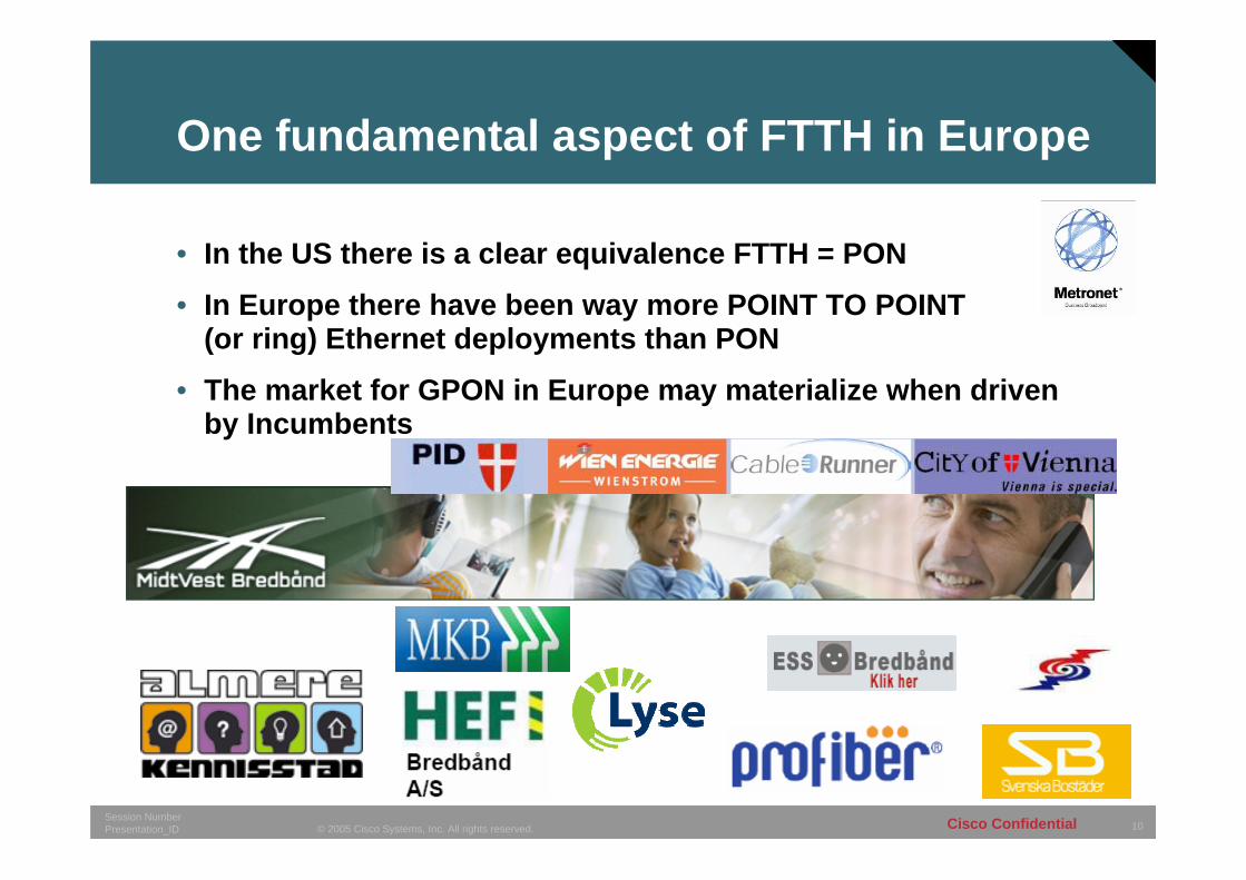
One fundamental aspect of FTTH in Europe
• In the US there is a clear equivalence FTTH = PON
• In Europe there have been way more POINT TO POINT (or ring) Ethernet deployments than PON
• The market for GPON in Europe may materialize when driven by Incumbents
11© 2005 Cisco Systems, Inc. All rights reserved.Session NumberPresentation_ID Cisco Confidential
Passive Optical Networks (PON)
111111© 2003, Cisco Systems, Inc. All rights reserved.Presentation_ID
12© 2005 Cisco Systems, Inc. All rights reserved.Session NumberPresentation_ID Cisco Confidential
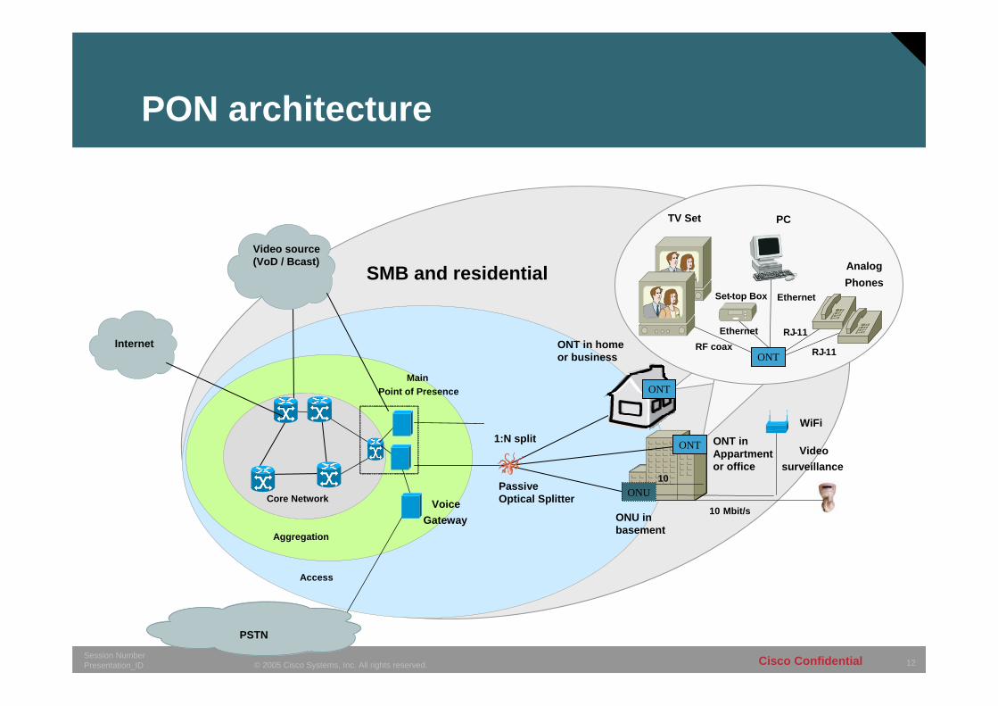
Core Network
Aggregation
Access
Main Point of Presence
Internet
PSTN
ONU in basement
Voice Gateway
SMB and residential
10 Passive Optical Splitter
10 Mbit/s
WiFi
Videosurveillance
1:N split
Video source (VoD / Bcast)
ONT
PCTV Set
Ethernet
RJ-11
RJ-11Ethernet
Set-top Box
AnalogPhones
RF coax
ONT in Appartment or office
ONT in home or business
ONT
ONU
ONT
PON architecture
13© 2005 Cisco Systems, Inc. All rights reserved.Session NumberPresentation_ID Cisco Confidential
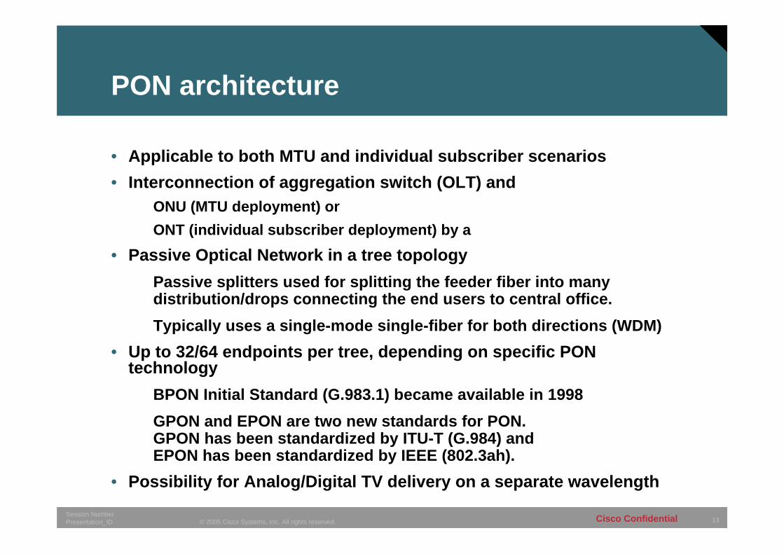
PON architecture
• Applicable to both MTU and individual subscriber scenarios• Interconnection of aggregation switch (OLT) and
ONU (MTU deployment) orONT (individual subscriber deployment) by a
• Passive Optical Network in a tree topologyPassive splitters used for splitting the feeder fiber into many distribution/drops connecting the end users to central office.Typically uses a single-mode single-fiber for both directions (WDM)
• Up to 32/64 endpoints per tree, depending on specific PON technology
BPON Initial Standard (G.983.1) became available in 1998GPON and EPON are two new standards for PON. GPON has been standardized by ITU-T (G.984) and EPON has been standardized by IEEE (802.3ah).
• Possibility for Analog/Digital TV delivery on a separate wavelength
14© 2005 Cisco Systems, Inc. All rights reserved.Session NumberPresentation_ID Cisco Confidential
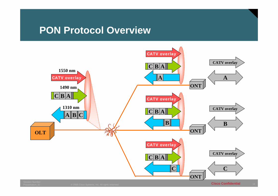
PON Protocol Overview
OLT
C B A1490 nm
C B A
C B A
C B A
CBA1310 nm
A
C
B
ONT
ONT
ONT
A
CATV overlay
B
CATV overlay
C
CATV overlay
CATV overlay
CATV overlay
CATV overlay
CATV overlay
1550 nm
15© 2005 Cisco Systems, Inc. All rights reserved.Session NumberPresentation_ID Cisco Confidential
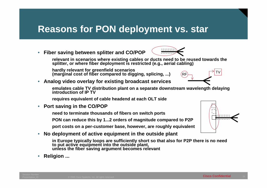
Reasons for PON deployment vs. star
• Fiber saving between splitter and CO/POPrelevant in scenarios where existing cables or ducts need to be reused towards the splitter, or where fiber deployment is restricted (e.g., aerial cabling)hardly relevant for greenfield scenarios (marginal cost of fiber compared to digging, splicing, ...)
• Analog video overlay for existing broadcast servicesemulates cable TV distribution plant on a separate downstream wavelength delaying introduction of IP TVrequires equivalent of cable headend at each OLT side
• Port saving in the CO/POPneed to terminate thousands of fibers on switch portsPON can reduce this by 1...2 orders of magnitude compared to P2Pport costs on a per-customer base, however, are roughly equivalent
• No deployment of active equipment in the outside plantin Europe typically loops are sufficiently short so that also for P2P there is no need to put active equipment into the outside plant, unless the fiber saving argument becomes relevant
• Religion ...
RF TV
16© 2005 Cisco Systems, Inc. All rights reserved.Session NumberPresentation_ID Cisco Confidential
Splitter deployment
Three possibilities to place splitter1. CO/POP
– backhaul of all the fibers to the CO/POP and termination on ODF– no fiber cost saving– port saving in the CO/POP compared to P2P– maximum flexibility to allocate customers to trees and change architecture
in the future to P2P2. Buried in the field
- static allocation of customers to trees- feasible for new-builds where customer acceptance is given- maximum fiber saving towards the CO/POP- no flexibility- splicing in the field required
3. In street cabinet- flexible allocation of customers to trees or even P2P fibers if available- feasible for overbuilds with unpredictable take rate- maximum fiber saving towards the CO/POP- splicing and street cabinet in the field required (expensive!)
17© 2005 Cisco Systems, Inc. All rights reserved.Session NumberPresentation_ID Cisco Confidential
Issues with PONs
• Bandwidth is shared among all users on the tree • Every endpoint (OLT, ONT, ...) has to operate at the aggregate bitrate
e.g. a GPON ONT delivering 40 Mbit/s to an end customer has to operate at 2.5 Gbit/s
• Significantly higher optical power required e.g. 20.4 dB (power ratio of 110) for 1:64 split => equivalent to 58 km of fiber at 1300 nm or 102 km at 1500 nm
• Theoretical maximum number of customers per tree is rarely reached due to take-up rates, unless expensive ODFs in the field are used to optimize utilization
• No resilienceOLT optics is single point of failurecorrupt CPE can impact entire PON tree
• In case of technology obsolescence all terminations on a tree need to be replaced
18© 2005 Cisco Systems, Inc. All rights reserved.Session NumberPresentation_ID Cisco Confidential
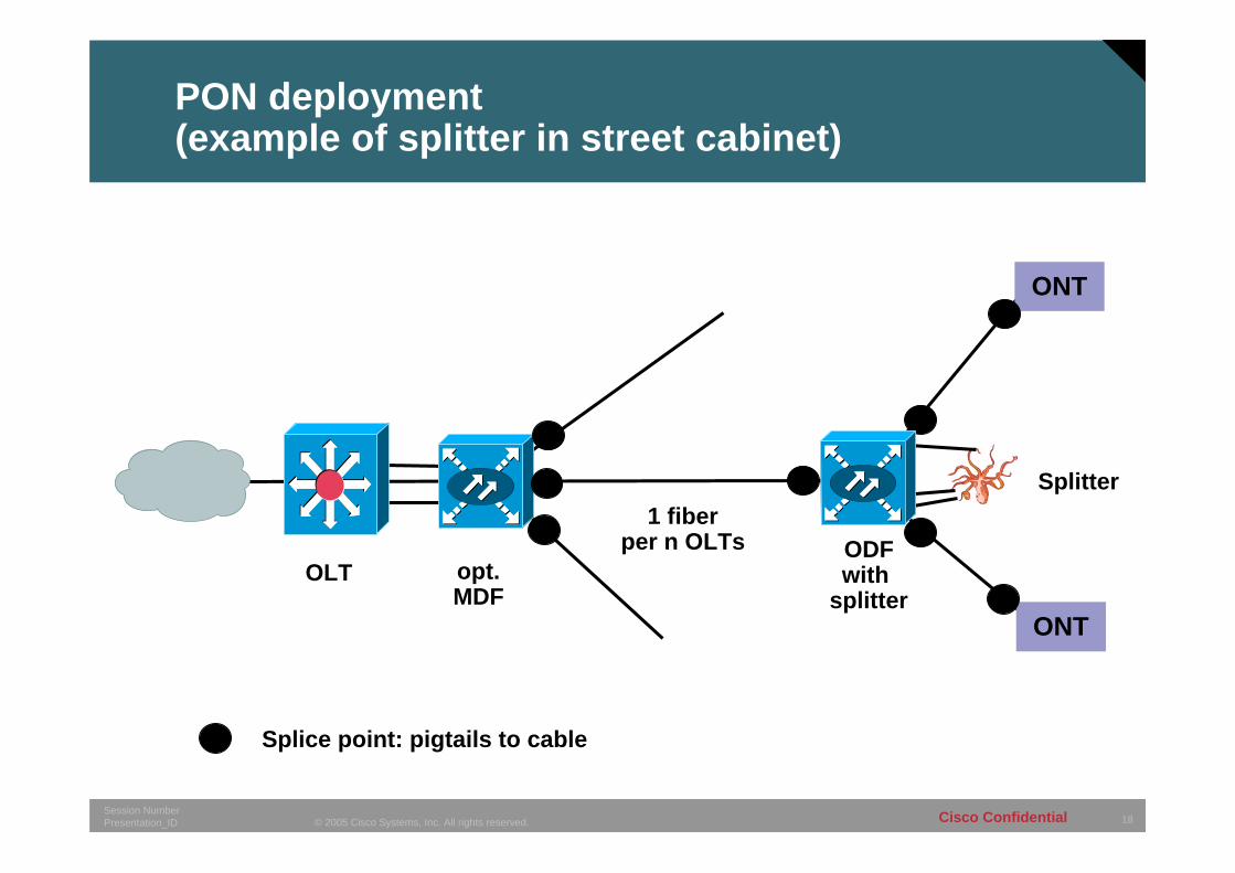
PON deployment (example of splitter in street cabinet)
OLT opt.MDF
ODFwith
splitter
Splice point: pigtails to cable
ONT
ONT
1 fiberper n OLTs
Splitter
19© 2005 Cisco Systems, Inc. All rights reserved.Session NumberPresentation_ID Cisco Confidential
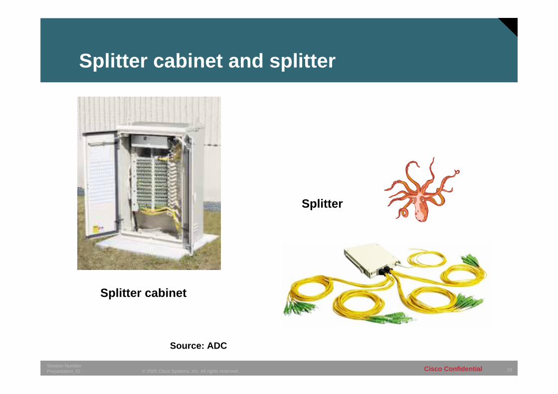
Splitter cabinet and splitter
Source: ADC
Splitter cabinet
Splitter
20© 2005 Cisco Systems, Inc. All rights reserved.Session NumberPresentation_ID Cisco Confidential
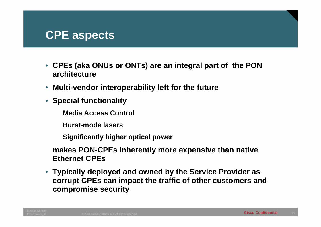
CPE aspects
• CPEs (aka ONUs or ONTs) are an integral part of the PON architecture
• Multi-vendor interoperability left for the future
• Special functionalityMedia Access Control
Burst-mode lasers
Significantly higher optical power
makes PON-CPEs inherently more expensive than native Ethernet CPEs
• Typically deployed and owned by the Service Provider as corrupt CPEs can impact the traffic of other customers and compromise security

21© 2005 Cisco Systems, Inc. All rights reserved.Session NumberPresentation_ID Cisco Confidential
ONU/OLT ratio forecast for Japan
166493 663 813 903 953
280
1,597
2,947
4,647
5,847
6,647
1.69
3.24
4.44
5.72
6.486.97
-
1,000
2,000
3,000
4,000
5,000
6,000
7,000
8,000
9,000
10,000
2004 Actual 2005Prospect
2006Forecast
2007Forecast
2008Forecast
2009Forecast
0.00
1.00
2.00
3.00
4.00
5.00
6.00
7.00
8.00
OLTONUONU/OLT Ratio
Source: FCR
22© 2005 Cisco Systems, Inc. All rights reserved.Session NumberPresentation_ID Cisco Confidential
Star Architecture or Point-to-Point (P2P) orhome run fiber
222222© 2003, Cisco Systems, Inc. All rights reserved.Presentation_ID
23© 2005 Cisco Systems, Inc. All rights reserved.Session NumberPresentation_ID Cisco Confidential
Core Network
Aggregation
Access
Main Point of Presence
Internet
PSTN
Access switch in basement
Voice Gateway
SMB and residential
10
10 Mbit/s
WiFi
Videosurveillance
Video source (VoD / Bcast)
ONT
PCTV Set
Ethernet
RJ-11
RJ-11Ethernet
Set-top Box
AnalogPhones
ONT in Appartment or office
ONT in home or business
ONT
ONT
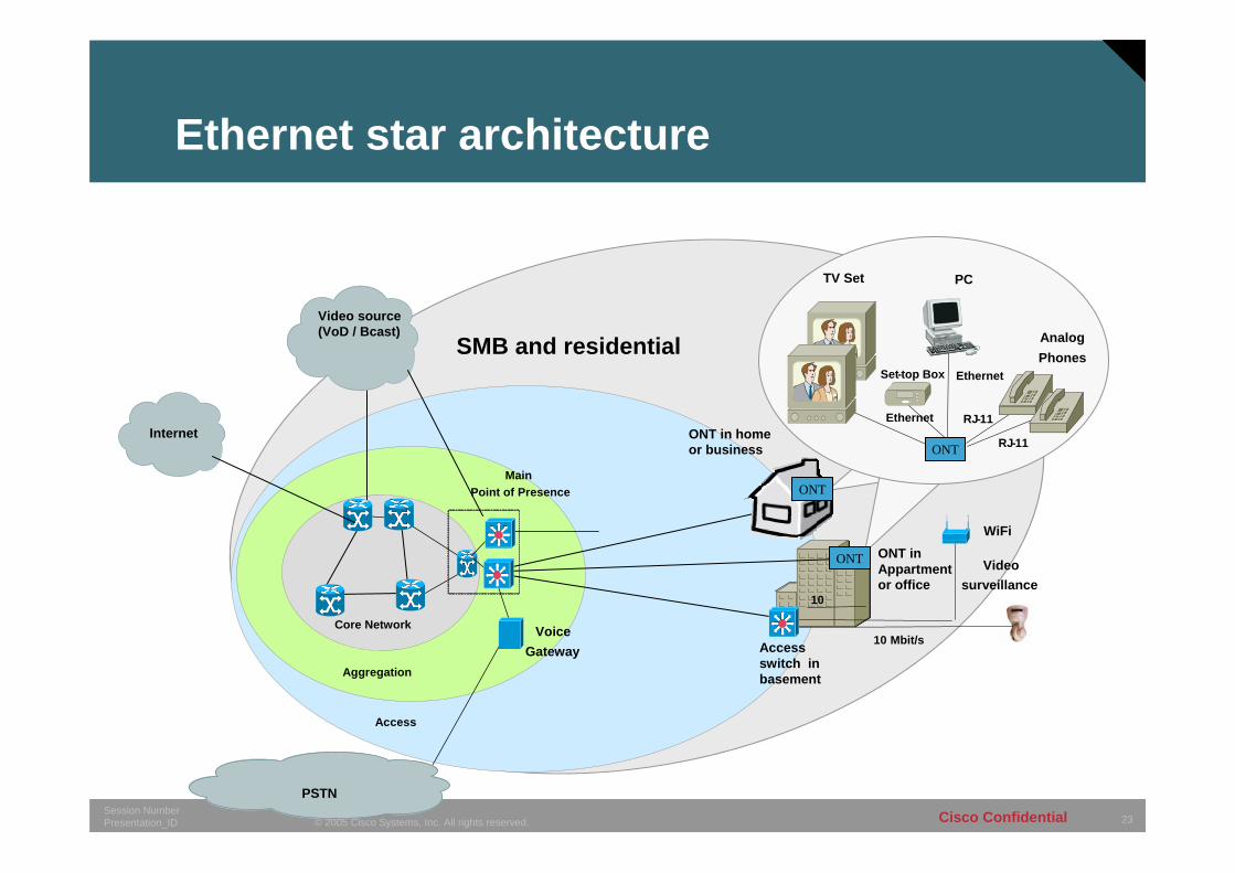
Ethernet star architecture
24© 2005 Cisco Systems, Inc. All rights reserved.Session NumberPresentation_ID Cisco Confidential
Ethernet star architecture(aka home run)
• Fiber access to individual subscribers (e.g. single family residences)
Access switches in CO or cabinetSingle mode single or dual fibre
• MTU deployments for residential, SMB, and Enterprise customers
Access switches in basement of MTU; last drop via Cat5, MMF, EoVDSL
• Increased resilience can be achieved by dual homing of access switches (second pair of fibers)
• Very flexible and future proof solution as it allows virtually unlimited bandwidth per customer
• No splices in the field needed if, e.g., microduct technology is used
25© 2005 Cisco Systems, Inc. All rights reserved.Session NumberPresentation_ID Cisco Confidential
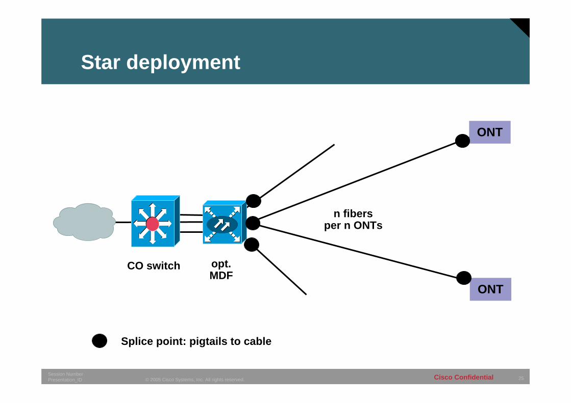
Star deployment
CO switch opt.MDF
Splice point: pigtails to cable
ONT
ONT
n fibersper n ONTs
26© 2005 Cisco Systems, Inc. All rights reserved.Session NumberPresentation_ID Cisco Confidential
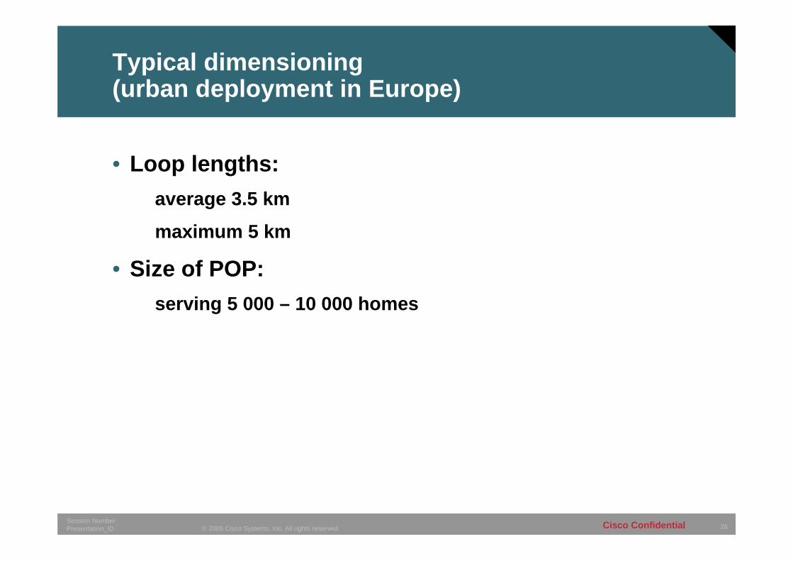
Typical dimensioning(urban deployment in Europe)
• Loop lengths:average 3.5 km
maximum 5 km
• Size of POP:serving 5 000 – 10 000 homes
27© 2005 Cisco Systems, Inc. All rights reserved.Session NumberPresentation_ID Cisco Confidential
CPE aspects
• CPEs can be commodity items purchased at a retail store
• No interoperability issues• No special functionality required
No Media Access ControlNo Burst-mode lasers
CPEs less expensive than PON CPEs• Can be deployed and owned by the customer as
corrupt CPEs can not impact the traffic of other customers or compromise security
just switch off the port in case of insane CPE behaviour

28© 2005 Cisco Systems, Inc. All rights reserved.Session NumberPresentation_ID Cisco Confidential
Open Access
282828© 2003, Cisco Systems, Inc. All rights reserved.Presentation_ID
29© 2005 Cisco Systems, Inc. All rights reserved.Session NumberPresentation_ID Cisco Confidential
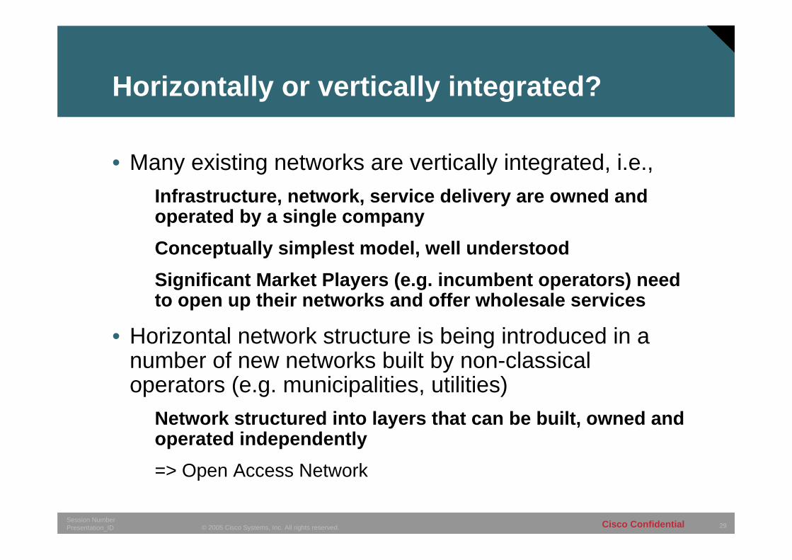
Horizontally or vertically integrated?
• Many existing networks are vertically integrated, i.e.,Infrastructure, network, service delivery are owned and operated by a single companyConceptually simplest model, well understoodSignificant Market Players (e.g. incumbent operators) need to open up their networks and offer wholesale services
• Horizontal network structure is being introduced in a number of new networks built by non-classical operators (e.g. municipalities, utilities)
Network structured into layers that can be built, owned and operated independently=> Open Access Network
30© 2005 Cisco Systems, Inc. All rights reserved.Session NumberPresentation_ID Cisco Confidential
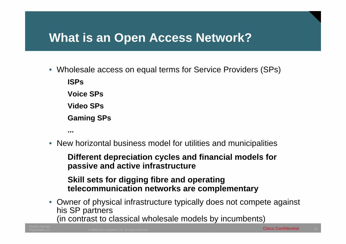
What is an Open Access Network?
• Wholesale access on equal terms for Service Providers (SPs)ISPsVoice SPsVideo SPsGaming SPs...
• New horizontal business model for utilities and municipalities
Different depreciation cycles and financial models for passive and active infrastructureSkill sets for digging fibre and operating telecommunication networks are complementary
• Owner of physical infrastructure typically does not compete against his SP partners (in contrast to classical wholesale models by incumbents)
31© 2005 Cisco Systems, Inc. All rights reserved.Session NumberPresentation_ID Cisco Confidential
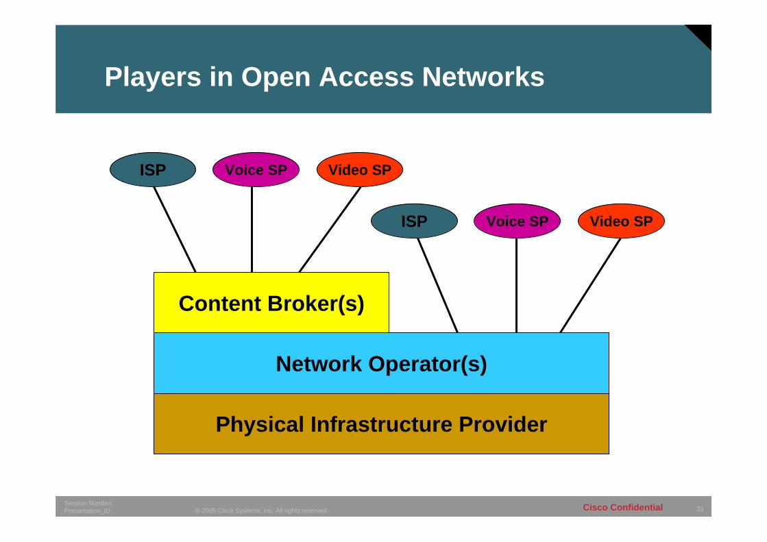
Physical Infrastructure Provider
Network Operator(s)
Content Broker(s)
ISP Voice SP Video SP
ISP Voice SP Video SP
Players in Open Access Networks
32© 2005 Cisco Systems, Inc. All rights reserved.Session NumberPresentation_ID Cisco Confidential
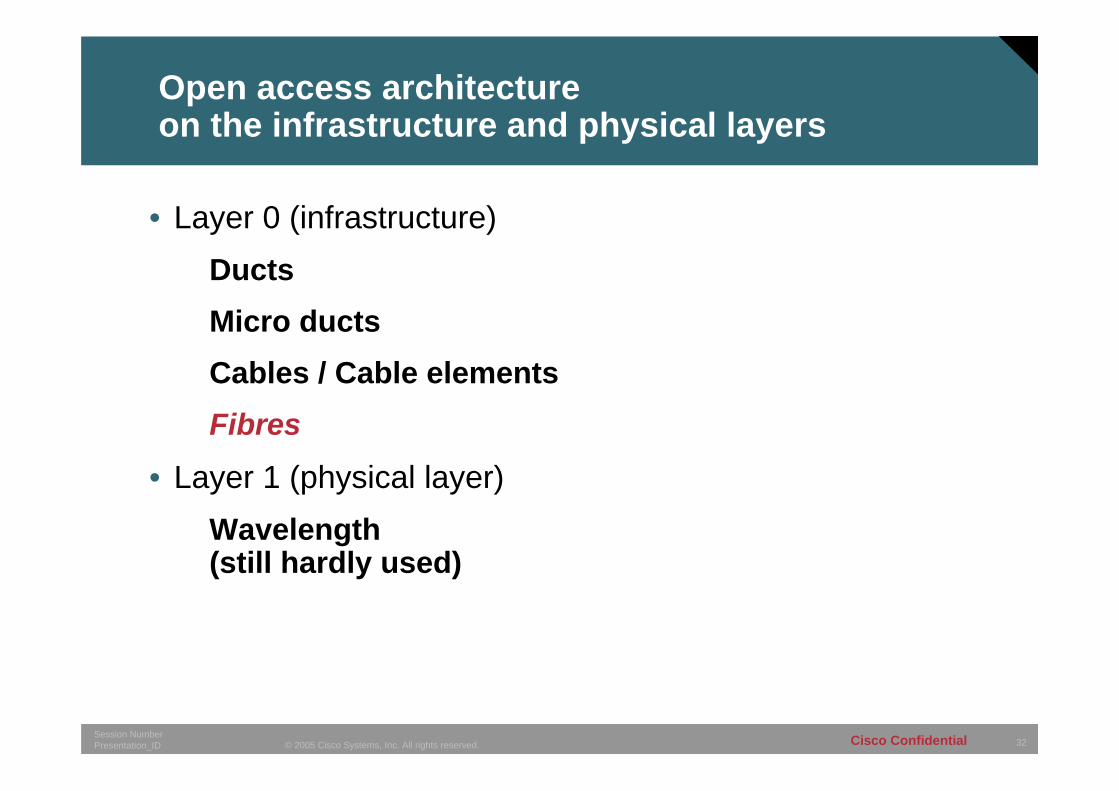
Open access architecture on the infrastructure and physical layers
• Layer 0 (infrastructure)DuctsMicro ductsCables / Cable elementsFibres
• Layer 1 (physical layer)Wavelength (still hardly used)
33© 2005 Cisco Systems, Inc. All rights reserved.Session NumberPresentation_ID Cisco Confidential
Open access architecture on architectural layers
• Layer 2 (Ethernet)Service / provider specific VLANsL2TP over IP infrastructure (hardly used)PPPoE (not used in FTTH deployments, lack of flexibility)
• Layer 3 (IP / MPLS)Standard IP peering agreements between content aggregator and SPMPLS VPN-like

34© 2005 Cisco Systems, Inc. All rights reserved.Session NumberPresentation_ID Cisco Confidential
Microduct technology
343434© 2003, Cisco Systems, Inc. All rights reserved.Presentation_ID
35© 2005 Cisco Systems, Inc. All rights reserved.Session NumberPresentation_ID Cisco Confidential
Microduct technology
• Microducts are small plastic tubes (down to 3mm diameter) which provide a continuous physical channel between endpoints (e.g. CO to customer)
• After installation of the microduct fiber is blown into it as a single strand without any intermediate splices. Up to about 6km of fiber can be inserted in a single blow.
• Microducts are bundled in outer ducts for easy deployment in trenches or sewers
• Routing of individual microducts from one duct to another is typically performed in small underground cabinets, and pieces of microducts are interconnected using muff couplers
36© 2005 Cisco Systems, Inc. All rights reserved.Session NumberPresentation_ID Cisco Confidential
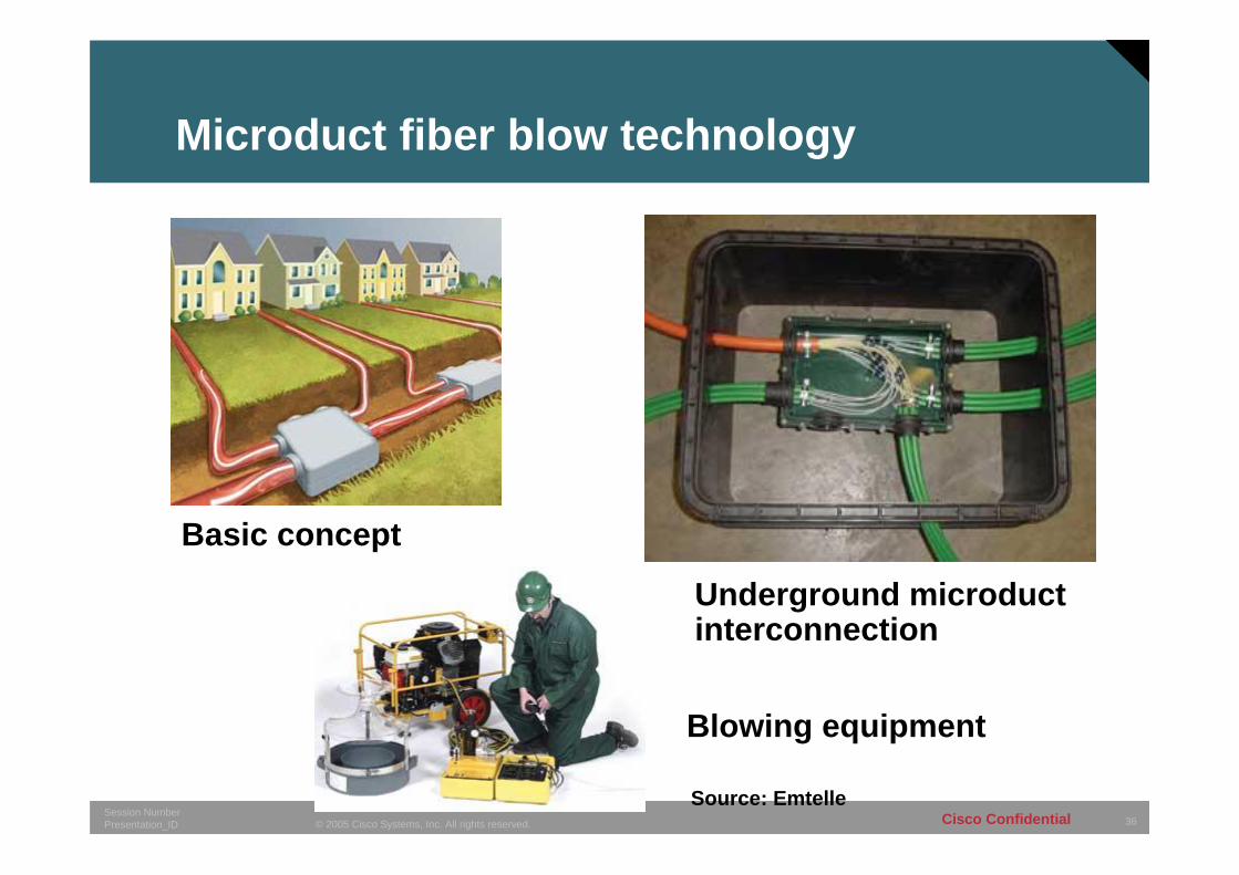
Microduct fiber blow technology
Basic concept
Underground microductinterconnection
Blowing equipment
Source: Emtelle

37© 2005 Cisco Systems, Inc. All rights reserved.Session NumberPresentation_ID Cisco Confidential
Summary
373737© 2003, Cisco Systems, Inc. All rights reserved.Presentation_ID
38© 2005 Cisco Systems, Inc. All rights reserved.Session NumberPresentation_ID Cisco Confidential
What has been deployed so far?
• In the US the big incumbents are currently deploying BPON with plans for GPON in the future
Re-use of existing duct and outside cabinet structure
• In Japan NTT are deploying EPONRegulatory situation enforced lowest common denominator
• Virtually anywhere elseDeployment of Point-to-Point/Star Ethernet or Ethernet rings
Only very little traction for PONs
39© 2005 Cisco Systems, Inc. All rights reserved.Session NumberPresentation_ID Cisco Confidential
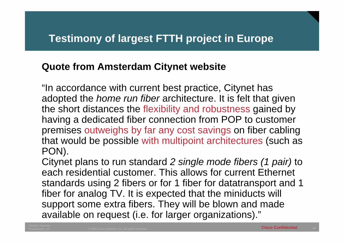
Testimony of largest FTTH project in Europe
Quote from Amsterdam Citynet website
“In accordance with current best practice, Citynet has adopted the home run fiber architecture. It is felt that given the short distances the flexibility and robustness gained by having a dedicated fiber connection from POP to customer premises outweighs by far any cost savings on fiber cablingthat would be possible with multipoint architectures (such as PON).Citynet plans to run standard 2 single mode fibers (1 pair) to each residential customer. This allows for current Ethernet standards using 2 fibers or for 1 fiber for datatransport and 1 fiber for analog TV. It is expected that the miniducts will support some extra fibers. They will be blown and made available on request (i.e. for larger organizations).”
40© 2005 Cisco Systems, Inc. All rights reserved.Session NumberPresentation_ID Cisco Confidential
Conclusion
• Fiber deployment to residences is a large investment into the future
• Every deployment scheme for FTTH networks has its own merits
• PONs can optimize deployment cost in the very short term, but do not represent a very future-proof investment as they constitute bottle-necks built into the physical infrastructure
• Star architectures represent the most future-proof solution which can provide virtually unlimited bitrates to subscribers. Individual subscribers can be migrated to more powerful technologies as needed without impacting the service to other subscribers