Embed Size (px)
Citation preview

For more information about the IFP-1000, or tolocate your nearest source, please call1-800-446-6444 or in Minnesota 612-493-6435Or Write to: Silent Knight Sales7550 Meridian CircleMaple Grove, Mn 55369-4927
Product Overview
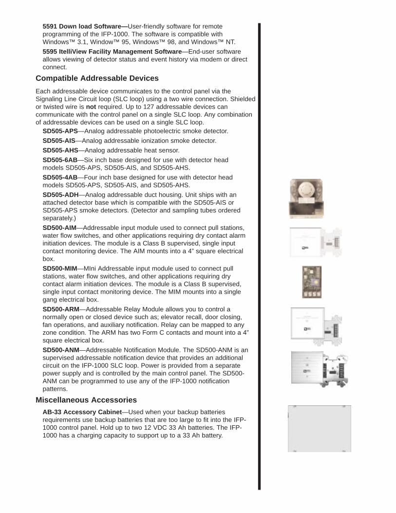
The IFP-1000 is a 1016 point intelligent analog/addressable firecontrol panel. The IFP-1000 has six on-board Flexput™ circuits thatcan be configured for notification outputs, or for conventional smokedetector (either Class A or Class B) inputs. The control panel alsohas a built-in dual line digital fire communicator, Form C troublerelay, and two programmable Form C relays. The firmware haspowerful features such as detector sensitivity, day/night thresholds,drift compensation and pre-trouble maintenance alert.
The basic IFP-1000 system has a single SLC loop, which cansupport 127 SLC devices, and can be expanded to 1016 points byadding 5815XL Signalling Line Circuit Expanders. Other devicesthat can be added to the system are the RA-1000 RemoteAnnunciator, the Model 5824 Serial/Parallel Interface (for printingsystem reports), and the RPS-1000 Intelligent Power Module.Features
• Up to 1016 analog addressable points.
• Supports Class B (Style 4) and Class A (Style 6) configuration for SLC,and SBUS.
• Distributed, intelligent power.
• Sensor sensitivity settings.
• Day/Night sensitivity setting.
• Automatic drift compensation.
• Flexput™ I/O circuits. Flexput circuits can be configured for notificationoutputs, or conventional smoke detector inputs. Notification circuits canbe configured as Class A (Style Z) or Class B (Style Y). 2- and 4-wiresmoke detectors can be configured as Class A (Style D) or Class B(Style B).
• Built-in annunciator with a backlit 80-character LCD display.
• RS-485 bus provides communication to system accessories.
• Built-in RS-232 interface for programming via PC.
• Built-in digital communicator.
• Built-in Form C trouble relay rated at 2.5 amps at 24 VDC.
• Two built-in Form C programmable relays rated at 2.5 amps at 24VDC.
• Individual addressable devices can be tested.
• SLC device locator can be used to locate a single or multiple deviceson a SLC loop.
• Uses standard wire—no shielded or twisted pair required.
• System automatically tests the addressable devices.
• Seven preset notification cadence patterns including ANSI 3.41 andfour user programmable patterns.
• Jumpstart® auto-programming.
• Built-in UL listed digital communicator for remote reporting of systemactivity and system programming.
IntelligentFire Panel
IFP-10001016 point Analog/Addressable Fire Alarm
Control System
P/N 350093B, 3/3/99
Copyright © 1999 Silent Knight
Flexput™ is a Trademark of Silent Knight
Jumpstart® is a Register Trademark ofSilent Knight
• Any combination of addressable devicescan be used on a single SLC loop (up to a127 devices)
MEA429-92-E Vol. 9
Built-in Digital Communicator Operation
The communicator has the ability to seize two telephone lines to reportalarms and troubles to a monitoring facility. Both phone lines aresupervised and will activate a trouble signal if a line failure is sustained formore than 45 seconds. Other communication features include:• Retry if communication fails
• Dual phone line capability
• programmable download computer number
• touchtone or rotary dialing
• Can communicate in SIA or Ademco Contact ID.
• The communication format is programmable by account number. (Up to 4accounts per panel.)
Accessory Product Information
The 485 SBUS is a 4-wire data communication link between the IFP-1000and the devices listed below. The 485 SBUS uses non-shielded wire up to6,000 feet in length.
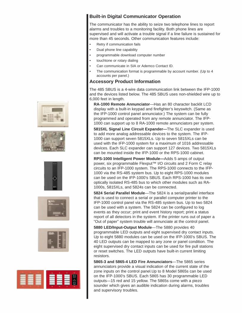
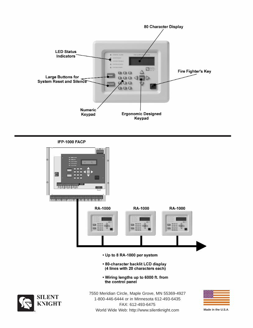
RA-1000 Remote Annunciator —Has an 80 character backlit LCDdisplay with a built-in keypad and firefighter’s keyswitch. (Same asthe IFP-1000 control panel annunciator.) The system can be fullyprogrammed and operated from any remote annunciator. The IFP-1000 can support up to 8 RA-1000 remote annunciators per system.
5815XL Signal Line Circuit Expander— The SLC expander is usedto add more analog addressable devices to the system. The IFP-1000 can support seven 5815XLs. Up to seven 5815XLs can beused with the IFP-1000 system for a maximum of 1016 addressabledevices. Each SLC expander can support 127 devices. Two 5815XLscan be mounted inside the IFP-1000 or the RPS-1000 cabinet.
RPS-1000 Intelligent Power Module— Adds 5 amps of outputpower, six programmable Flexput™ I/O circuits and 2 Form C relaycircuits to an IFP-1000 system. The RPS-1000 connects to the IFP-1000 via the RS-485 system bus. Up to eight RPS-1000 modulescan be used on the IFP-1000’s SBUS. Each RPS-1000 has its ownoptically isolated RS-485 bus to which other modules such as RA-1000s, 5815XLs, and 5824s can be connected.
5824 Serial Parallel Module —The 5824 is a serial/parallel interfacethat is used to connect a serial or parallel computer printer to theIFP-1000 control panel via the RS-485 system bus. Up to two 5824can be used with a system. The 5824 can be configured to logevents as they occur; print and event history report; print a statusreport of all detectors in the system. If the printer runs out of paper a“Out of paper” system trouble will annunciate at the control panel.
5880 LED/Input-Output Module —The 5880 provides 40programmable LED outputs and eight supervised dry contact inputs.Up to eight 5880 modules can be used on the IFP-1000’s SBUS. The40 LED outputs can be mapped to any zone or panel condition. Theeight supervised dry contact inputs can be used for fire pull stationsor reset switches. The LED outputs have built-in current limitingresistors.
5865-3 and 5865-4 LED Fire Annunciators —The 5865 seriesannunciators provide a visual indication of the current state of thezone inputs on the control panel.Up to 8 Model 5865s can be usedon the IFP-1000’s SBUS. Each 5865 has 30 programmable LEDoutputs—15 red and 15 yellow. The 5865s come with a piezosounder which gives an audible indication during alarms, troublesand supervisory troubles.
5591 Down load Software— User-friendly software for remoteprogramming of the IFP-1000. The software is compatible withWindows™ 3.1, Window™ 95, Windows™ 98, and Windows™ NT.
5595 ItelliV iew Facility Management Software —End-user softwareallows viewing of detector status and event history via modem or directconnect.
Compatible Addressable Devices
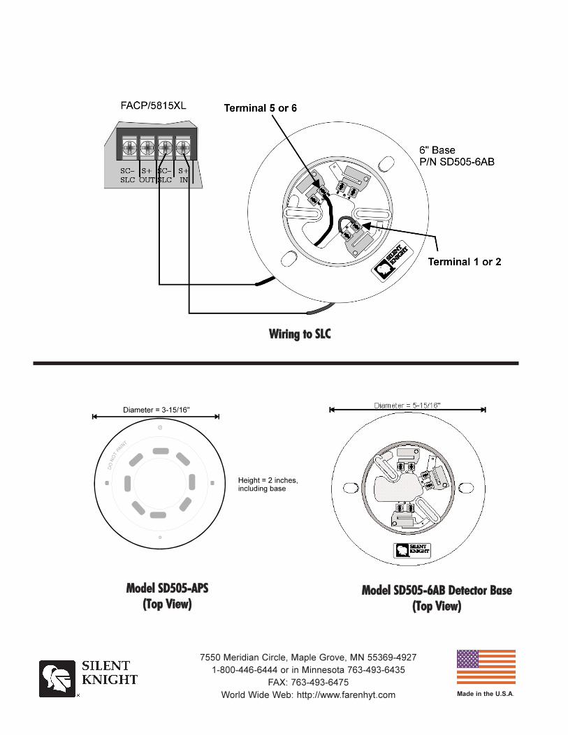
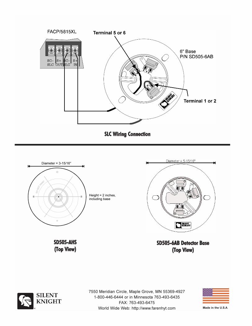
Each addressable device communicates to the control panel via theSignaling Line Circuit loop (SLC loop) using a two wire connection. Shieldedor twisted wire is not required. Up to 127 addressable devices cancommunicate with the control panel on a single SLC loop. Any combinationof addressable devices can be used on a single SLC loop.
SD505-APS—Analog addressable photoelectric smoke detector.
SD505-AIS—Analog addressable ionization smoke detector.
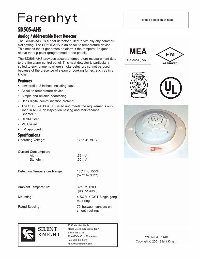
SD505-AHS—Analog addressable heat sensor.
SD505-6AB—Six inch base designed for use with detector headmodels SD505-APS, SD505-AIS, and SD505-AHS.
SD505-4AB—Four inch base designed for use with detector headmodels SD505-APS, SD505-AIS, and SD505-AHS.
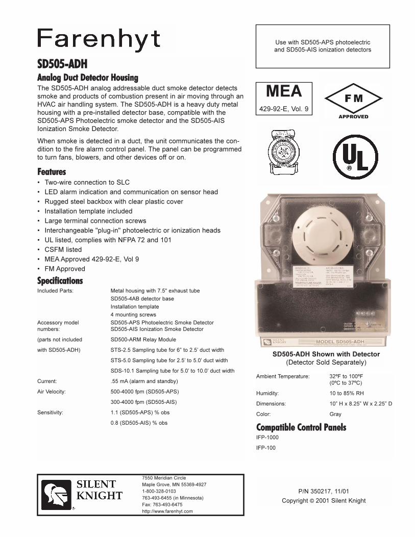
SD505-ADH—Analog addressable duct housing. Unit ships with anattached detector base which is compatible with the SD505-AIS orSD505-APS smoke detectors. (Detector and sampling tubes orderedseparately.)
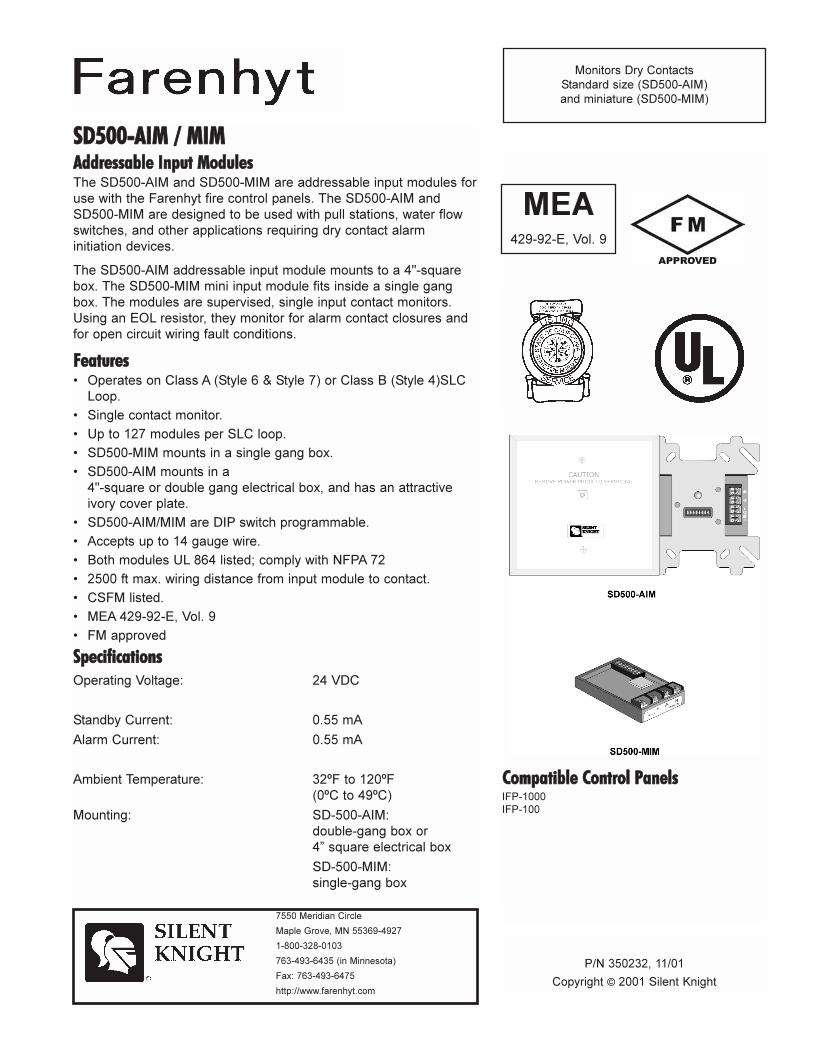
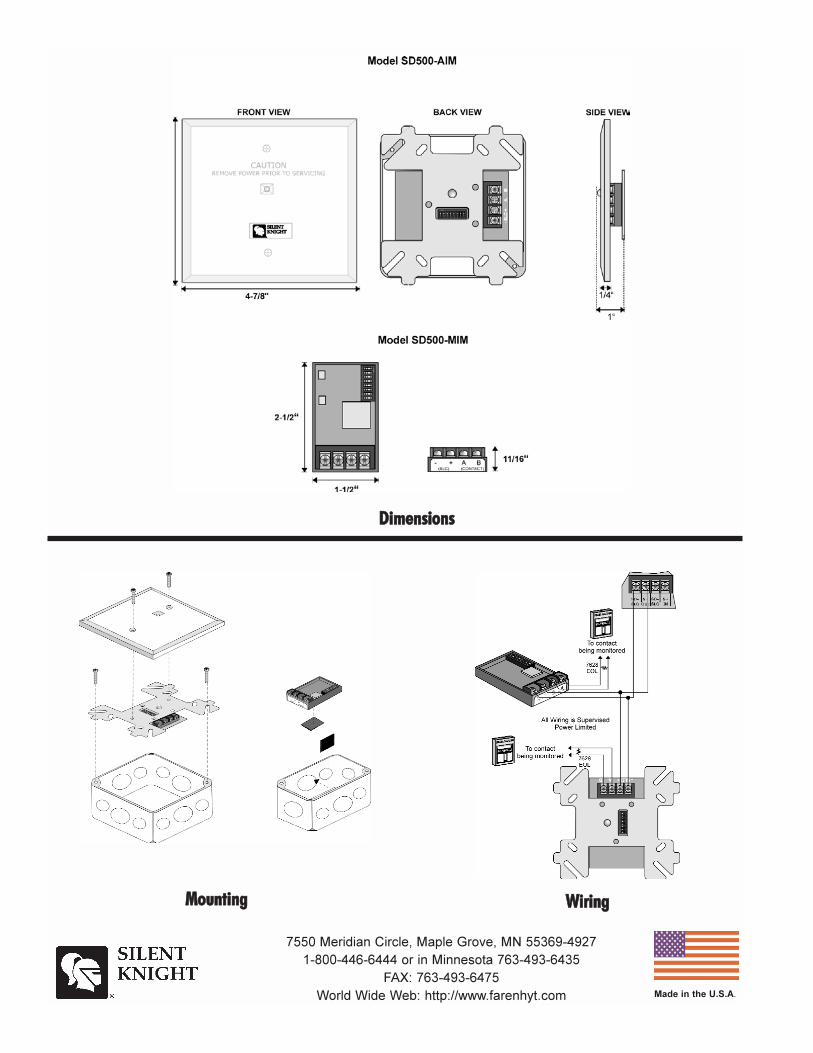
SD500-AIM—Addressable input module used to connect pull stations,water flow switches, and other applications requiring dry contact alarminitiation devices. The module is a Class B supervised, single inputcontact monitoring device. The AIM mounts into a 4” square electricalbox.
SD500-MIM—MIni Addressable input module used to connect pullstations, water flow switches, and other applications requiring drycontact alarm initiation devices. The module is a Class B supervised,single input contact monitoring device. The MIM mounts into a singlegang electrical box.
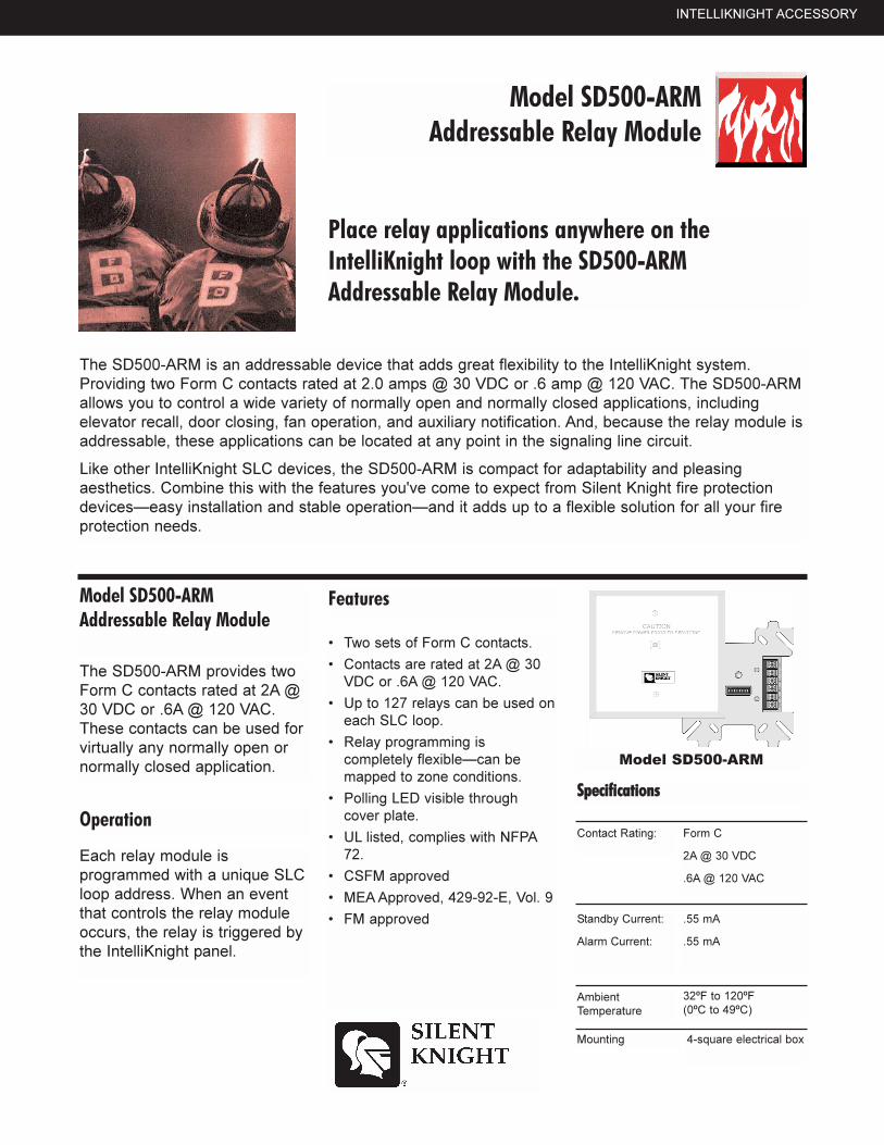
SD500-ARM—Addressable Relay Module allows you to control anormally open or closed device such as; elevator recall, door closing,fan operations, and auxiliary notification. Relay can be mapped to anyzone condition. The ARM has two Form C contacts and mount into a 4”square electrical box.
SD500-ANM—Addressable Notification Module. The SD500-ANM is ansupervised addressable notification device that provides an additionalcircuit on the IFP-1000 SLC loop. Power is provided from a separatepower supply and is controlled by the main control panel. The SD500-ANM can be programmed to use any of the IFP-1000 notificationpatterns.
Miscellaneous Accessories
AB-33 Accessory Cabinet —Used when your backup batteriesrequirements use backup batteries that are too large to fit into the IFP-1000 control panel. Hold up to two 12 VDC 33 Ah batteries. The IFP-1000 has a charging capacity to support up to a 33 Ah battery.
Specifications
Electrical Specifications
Primary AC: 230* / 120 VRMS @ 50 / 60 hz, 2.5A
Total Accessory Load: 4 A @ 24 VDC5 Amps @ 24 VDC of power-limited notificationpower
Standby Current: 140 mAAlarm Current: 260 mA
Battery Charging Capacity: Up to 33 Ah
*Requires optional transformer
Flexput™ Circuits
Six programmable circuits which can beprogrammed individually as:
Notification Circuits: 3 amps of power-limited powerper circuit at 24 VDC.
Auxiliary Power Circuits: 3 amps of power-limitedpower per circuit at 24 VDC.
Initiation Circuit: 100 mA of power-limited power percircuit at 24 VDC.
Approvals
UL ListingNFPA 72 Central Station
Remote SignallingLocal Protective Signalling SystemsAuxiliary Protected Premises Unit
CSFM 7165-0559: 130
MEA 429-92-E Vol. 9
Indicator Lights
General Alarm (Red) On for alarmsSupervisory (Yellow) On when a
supervisory conditionexists
System Troubles(Yellow) On when a trouble
condition exists
System Silenced On when an alarm, (Yellow) trouble or supervisory
condition has beensilenced but not yet cleared
System Power (Green) On when power systems are normal;flashes for AC or DCfailure
Mechanical Specifications
Dimensions: 16”W x 26.4”H x 4.65”DWeight: 28 lbs. (12.8 kg)Color: RedTelephone Requirements FCC Part 15 and
Part 68 approved
Type of Jack: RJ31X (two required)
Made in the U.S.A .
7550 Meridian Circle, Maple Grove, MN 55369-49271-800-446-6444 or in Minnesota 612-493-6435
FAX: 612-493-6475World Wide Web: http://www.silentknight.com
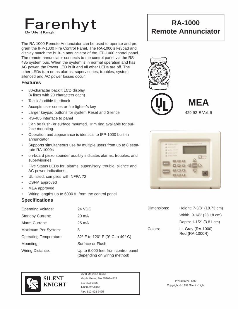
The RA-1000 Remote Annunciator can be used to operate and pro-gram the IFP-1000 Fire Control Panel. The RA-1000’s keypad anddisplay match the built-in annunciator of the IFP-1000 control panel.The remote annunciator connects to the control panel via the RS-485 system bus. When the system is in normal operation and hasAC power, the Power LED is lit and all other LEDs are off. Theother LEDs turn on as alarms, supervisories, troubles, systemsilenced and AC power losses occur.
Features
• 80-character backlit LCD display (4 lines with 20 characters each)
• Tactile/audible feedback
• Accepts user codes or fire fighter’s key
• Larger keypad buttons for system Reset and Silence
• RS-485 interface to panel
• Can be flush- or surface mounted. Trim ring available for sur-face mounting.
• Operation and appearance is identical to IFP-1000 built-inannunciator
• Supports simultaneous use by multiple users from up to 8 sepa-rate RA-1000s
• on-board piezo sounder audibly indicates alarms, troubles, andsupervisories
• Five Status LEDs for; alarms, supervisory, trouble, silence andAC power indications.
• UL listed, complies with NFPA 72
• CSFM approved
• MEA approved
• Wiring lengths up to 6000 ft. from the control panel
Specifications
Operating Voltage: 24 VDC
Standby Current: 20 mA
Alarm Current: 25 mA
Maximum Per System: 8
Operating Temperature: 32° F to 120° F (0° C to 49° C)
Mounting: Surface or Flush
Wiring Distance: Up to 6,000 feet from control panel(depending on wiring method)
Dimensions: Height: 7-3/8” (18.73 cm)
Width: 9-1/8” (23.18 cm)
Depth: 1-1/2” (3.81 cm)
Colors: Lt. Gray (RA-1000)Red (RA-1000R)
RA-1000Remote Annunciator
7550 Meridian Circle
Maple Grove, Mn 55369-4927
612-493-6455
1-800-328-0103
Fax: 612-493-7475
P/N 350071, 5/99
Copyright © 1999 Silent Knight
MEA429-92-E Vol. 9
7550 Meridian Circle, Maple Grove, MN 55369-49271-800-446-6444 or in Minnesota 612-493-6435
FAX: 612-493-6475World Wide Web: http://www.silentknight.com Made in the U.S.A .


���������������
� ��������� ������������������
���������� ����� �� !"���� �
�������������������������� �� ������������������ ������������������������ �������� ���������� ����������������#��$����� ��� �$����$���������������$��! �������� �����$��������%&����� � ��������������� ���$��$����'���$�������(���������� ���)���"������*&��+�
,��������%&���� !����$����$�� !$���$���� ��� ��$!��$�� ����������-�� �!���+������� ���$��"�$�� ���������������!���.�-��� � !�$��! �������+�,��������%&��� ����$�� (��� ��������$��$�� ��$�����������/ ���������%&0�"$���� !�$��"���(���� ����������� ����������������$�� (���� ��� !������$�����$�� ��$�����$��!��� ��1�"�����+�2�3�� �����*$��������! 3�������� ������������%&�� �����$�������$��$�� ����$"��� ���$�� ��4*���$��������� ����� �$���-$��$�%������$���� �3���+
��������������5 2 (��� �����������������������"$��
5 ��!����$�������$"���$����������(��� ���!���$���$���(������
5 &�� !$����� !����$�� �� ������ ��� ��$!��$�� �
5 0����%��� ��������� �$����
5 ��!���������� ���$��"�$�� ������������� ��������� ��� ���$���� ���! �������� ����$�6��� (�,/ "$����� !�����+�76��� (�,/
� �($�����'������ ����! ����������+8
5 9$��$�%������$����� �3���� �$�����
5 *��������$�$"��
5 :2 �������!������*�& ;�����;���'����!����
5 ��*/�&��� -��
5 /<& &��� -��
5 */�&��� -��
��������������������������=���$�����9 ��$��> �;%?��9��
��������� ���!��� �>��$��"�> +���!&&�$�!> +���!&
=���$�����,�!���$����> ��@*�� ����@*�7�@��� �?A@�8
4��$��-��B�!�����> C�D�� �� ��������
�������-���> �+CCD�%��+�D *,
&���9�� ����> ��%�����*�/
;����/�����$��������
/$����E� -��/�����A%?A�;
�%C��%��C%����
;�%?A�%?���7���/����� �$8
*$1>�;�%?A�%?;�
����>��(((+ $������+� !
���?�A%A�%<�9 �+�A
;����/�����$���������/$����E� -��/�����A%?A�;�%C��%??%???� �����/����� �$�;�%?A�%?��
*&F>�;�%?A�%?;�6 ����6����6�">�����>��(((+ $������+� ! ����������� � �+
���������� ���� ��!!""
##������ ������������������$$������ %%����&&''
##������ ������������((��)) ���������������� ))����$$������ %%����&&''
�������������
�� �������� �����������������
��������������������������
�������������������������� �� ������������������ ������ ����������������!����"���#$%����������������������&������������&�����������''��#������������ �!����"���#$%���������(���&�����' ����&��������� !����'������������������������������'����������' ����&��������(����������� � �����) �����''���������� ����* �
!����"���#$%�� �����������&�������' ����&���'���&��'������������������������'��������� ���� �!��������������������� �����&�������&���������������'�����+������'�,�������������������(��&���(���&���������� ���������������'�������,�����&'����&����������,������
��������������- .�+� ��������������������&�����(���
- $(���&�����' ����&���������
- ��' ������������(�������������
- /��������������''&��������� �������
- !����"���#$%�����/. .����������'�����������0&���'������&�#����������1�$ 2��3�� �������!�����������4�������������� ����2
- �1�4�������
- 45$ ������
- 14�� �����
��������������������������6 ��������7������8 2����9�7"�
�&����������&' ����8$���'8 ���'$�����(�8 ���'$
"���������!�' ����&���:����8 ��;1������;1�)�2;�����<�;�*
$'(�����!�' ����&��8 ��;1������;1�)�;�����9=;�*
4�&�����8 9��>:�9?6�! �����������'&������
:������ �����8 2�@ (��+���������������'�������������
2����4��������������
4� ���A�����4�����<=#9=�2
#B��#��B#���
2<�#9=�#<9���)���4��������*
1�C8�2<�#9=�#<92�
��� 8��+++ �������� ��'
���9�=#=�#5�7���=
2����4���������������4� ���A�����4�����<=#9=�2#B��#99<#<999�������4���������2<�#9=�#<9��
1$D8�2<�#9=�#<92�E�����E����E�(8���� 8��+++ �������� ��' ����������� � �
������ ������������ ��������������������
�������������������������� ����!!""
������������##��$$ ���������������� $$������������ ����!!""
�������������������������� �������� ���������������� ��������������������������� ��������������������������������������������������� ����������������������� ������ ��� ��������� ����������� ���������� ��� ��� ����!���������������������� ���� ����������� ��"���������� ���������������������#������������"������������$� $����������������������������� �����������%�%� �&���� ���������������!�
'�� �������������������� �������#������ �������� ������������� ����� ��������������������� ������� ��!������� ����� �������������������� ��� �#����"���#�� ������������������������ !
��������������( �"�"������ ����� �����)�
( )*��������� ������� �� ������� ������ �� ��� ��������
( +������������������,�"�����������������������
( % ��������� ����������� �������
( )���������� ����� ����� �����"�
( % ������ �������-����� -�������������������� �&���� ������
( .) ������#����������"����/0$ 12�� ��3�3
( ��04�������
( 4*��������52662*#�����6�
( 04��������
��������������������������% �������$����7 4���������� ��"����1!�-��,����������
�����58��������������
% ��������� ���������
5���� �� ������"��
������� ������ �����$��$��������������������������� ������7 �����%��%� �&���� ���������������
9������ ���� ������ �����+4�+��� �4�����
"�����������: ���2!�������� �����������;<����2!�= �����"����
����!�������� �����������2!�= ����!�= �����"����
���3�!3������� ������������!�= ���3�!�= �����"����
����� �7 !���� 9������� ����� �� :
���������� 7 ���5��������9�����$�:
>��5��������9�����%�:
�� ������� 7 3!3�9�����$�:�?����
�!@�9�����%�:�?����
$A/�>��231#�33A�3
��� ������B 2��3����� ��C ����
.���"���������$����������������� �������%� �� �&���� ����������
1����4������ �������
4�����D����#�4/���>;65621
3@��>2@�3�>
1;>56>;5���9� �4� �����:
0�,7�1;>56>;51�
����7AA"""!���� � �!���
���� �������������7 >2E0����3��E09�E�����>1E�:
������� 7 3�����@�?�+�
���� ��� �7 3�<���,�@!2�<�'�,�2!2�<��
�����7 D��
���������������� ������������ ��������%0$3���
%0$3��
���52662*#����!�6
����������� � �����������9����������������������� :

1����4������ �������#�4�����D����#�4/���>;656213@��55;;555����� �4� ������1;>56>;5>�
0F7�1;>56>;51�'�����'����'��7�����7AA"""!���� � �!��� ��������������!
��������������������
������������������
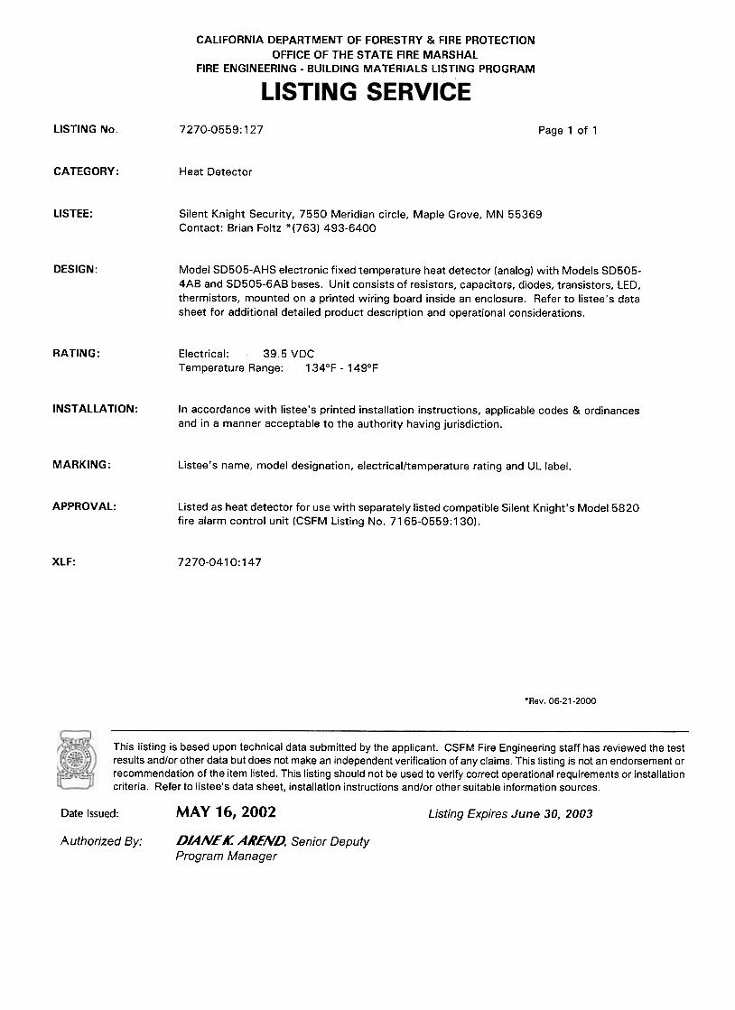
CALIFORNIA DEPARTMENT OF FORESTRY & FIRE PROTECTION OFFICE OF THE STATE FIRE MARSHAL
FIRE ENGINEERING - BUILDING MATERIALS LISTING PROGRAM
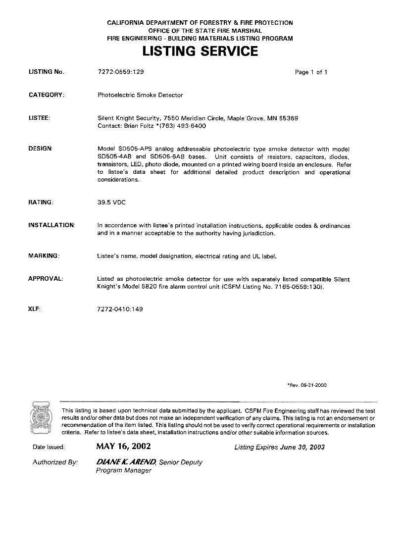
LISTING SERVICE LISTING No. 3240-0559:133 Page 1 of 1 CATEGORY: Duct Smoke Detector Housing/Base LISTEE: Silent Knight Security, 7550 Meridian Circle, Maple Grove, MN 55369
Contact: Brian Foltz *(763) 493-6400 DESIGN: Model SD505-ADH duct smoke detector unit. Unit consists of a metal enclosure, electrical
components, Model SD505-APS (CSFM Listing No. 7272-0559:129) or SD505-AIS (CSFM Listing No. 7271-0559:128) smoke detector with Model SD505-4AB or SD505-6AB bases, sampling and exhaust tubes. Refer to listee's data sheet for additional detailed product description and operational considerations.
RATING: 39.5 VDC INSTALLATION: In accordance with listee's printed installation instructions, applicable codes & ordinances
and in a manner acceptable to the authority having jurisdiction. MARKING: Listee's name, model designation, electrical rating and UL label. APPROVAL: Listed as duct smoke detector unit for use with separately listed compatible Silent Knight's
Model 5820 fire alarm control unit (CSFM Listing No. 7165-0559:130). Unit Model SD505-AIS detector head is suitable for air velocities between 300 and 4000 ft/min. Unit with Model SD505-APS detector head is suitable for air velocities between 500 and 4000 ft/min.
*Rev. 06-21-2000
This listing is based upon technical data submitted by the applicant. CSFM Fire Engineering staff has reviewed the test results and/or other data but does not make an independent verification of any claims. This listing is not an endorsement or recommendation of the item listed. This listing should not be used to verify correct operational requirements or installation criteria. Refer to listee’s data sheet, installation instructions and/or other suitable information sources.
Date Issued: MAY 17, 2001 Listing Expires June 30, 2002
Authorized By: BEN HO, Supervising Deputy Program Manager

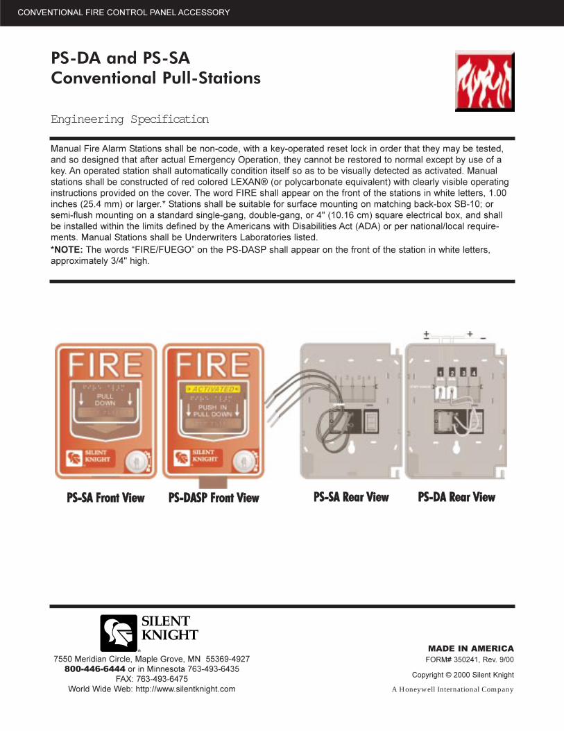
OOppeerraattiioonnThe single-action pull-station isactivated by a single pull-down ofthe alarm handle. The dual-actionversions require pushing in thehandle, then pulling the handledown for activation. The PS-DA/PS-SA manual pull stations areUL listed and meet the ADArequirement of a 5-lbs. maximumpull force to activate. Operatinginstructions are molded into thehandle along with Braille text.Molded terminal numbers can befound adjacent to the wiring termi-nals.
MMooddeellss::PS-SA� Single action with �pigtail�connections and a key lock reset.Pigtail wires are provided for con-nection to the Fire Alarm ControlPanel�s (FACP) initiation circuit.
PS-DA � Dual action model withscrew terminal connections and akey lock reset.
PS-DASP � Same as PS-DAexcept with both English andSpanish operating instructions.
FFeeaattuurreess::� UL Listed
� CSFM Listed
� Meets ADA requirements
� Operating instructions are mold-ed into the handle along withBraille text.
� Made of durable Lexan
� Available in Spanish
� Key resettable
� Easy to Install and operate
� Single or dual action
� Surface mount box available
SSppeecciiffiiccaattiioonn::Dimensions:
Height: 5-1/2� (13.97 cm)Width: 4� (10.16 cm)Depth: 1-7/16� (3.65 cm)
Operatingtemperature: 32°F to 120°F
(0°C to 49°C)
Electrical:Switch ContactRating: 0.25 A @ 30 VAC
or VDC
AAcccceessssoorriieess::SB-10 Surface Mount
Back-box
BG-TR Trim Ring
PS-DA and PS-SAConventional Pull-stations
The PS-DA/PS-SA Pull Stations are non-coded manual pull stations which provide a Fire Alarm Control Panel(FACP) with a single alarm initiating input signal. The PS-DA/PS-SA pull stations includes both single-action anddual-action models equipped with key lock / reset.It was designed to meet multiple applications with the installerand end-user in mind. Its innovative design, durable construction, and multiple mounting options make the PS-DA and PS-SA simple to install, maintain, and operate.
Easy to Install and Operate
PPSS--DDAA PPSS--DDAASSPP
CONVENTIONAL FIRE CONTROL PANEL ACCESSORY
CONVENTIONAL FIRE CONTROL PANEL ACCESSORY
PS-DA and PS-SAConventional Pull-Stations
Engineering Specification
Manual Fire Alarm Stations shall be non-code, with a key-operated reset lock in order that they may be tested,and so designed that after actual Emergency Operation, they cannot be restored to normal except by use of akey. An operated station shall automatically condition itself so as to be visually detected as activated. Manualstations shall be constructed of red colored LEXAN® (or polycarbonate equivalent) with clearly visible operatinginstructions provided on the cover. The word FIRE shall appear on the front of the stations in white letters, 1.00inches (25.4 mm) or larger.* Stations shall be suitable for surface mounting on matching back-box SB-10; orsemi-flush mounting on a standard single-gang, double-gang, or 4" (10.16 cm) square electrical box, and shallbe installed within the limits defined by the Americans with Disabilities Act (ADA) or per national/local require-ments. Manual Stations shall be Underwriters Laboratories listed.*NOTE: The words �FIRE/FUEGO� on the PS-DASP shall appear on the front of the station in white letters,approximately 3/4" high.
7550 Meridian Circle, Maple Grove, MN 55369-4927800-446-6444 or in Minnesota 763-493-6435
FAX: 763-493-6475World Wide Web: http://www.silentknight.com
MADE IN AMERICAFORM# 350241, Rev. 9/00
Copyright © 2000 Silent Knight
A Honeywell International Company
PPSS--SSAA FFrroonntt VViieeww PPSS--DDAASSPP FFrroonntt VViieeww PPSS--SSAA RReeaarr VViieeww PPSS--DDAA RReeaarr VViieeww
CALIFORNIA DEPARTMENT OF FORESTRY & FIRE PROTECTION OFFICE OF THE STATE FIRE MARSHAL
FIRE ENGINEERING - BUILDING MATERIALS LISTING PROGRAM
LISTING SERVICE LISTING No. 7150-0559:140 Page 1 of 1 CATEGORY: Boxes/Pull Stations LISTEE: Silent Knight Security, 7550 Meridian Cr., Maple Grove MN 55369 Contact: Brian Foltz (763) 493-6400 *FAX (763) 391-5464 DESIGN: Models PS-SA, PS-DA, PS-DASP fire alarm pull boxes. The PS series is a dual action pull
station that has normally open switch contacts. Refer to listee's data sheet for detailed product description and operational considerations.
INSTALLATION: In accordance with listee's printed installation instructions, applicable codes and ordinances
and in a manner acceptable to the authority having jurisdiction. MARKING: Listee's name, model number and UL label. APPROVAL: Listed as fire alarm pull boxes for use with separately listed compatible fire alarm control
units. XLF: 7150-0028:199
*Rev. 05-28-2004
This listing is based upon technical data submitted by the applicant. CSFM Fire Engineering staff has reviewed the test results and/or other data but does not make an independent verification of any claims. This listing is not an endorsement or recommendation of the item listed. This listing should not be used to verify correct operational requirements or installation criteria. Refer to listee’s data sheet, installation instructions and/or other suitable information sources.
Date Issued: JUNE 21, 2004 Listing Expires June 30, 2005
Authorized By: DIANE K. AREND, Senior Deputy Program Manager
�������������
�� �������� �����������������
�������������������������������� ��!�����"#$�%�����&�����'���!�����"�$�%
�������������������������������� ���������� �������������������� ��(��������"#$�����������"�$��������������)����� '��&��'����*��'���+��������,��������*������������ �����-�(��������"#$����������"�$������������������)��'����+���� '������������+�����*��+�+������������������ ������������.'����������������������&�������������/����-�
(��������"#$����������)����� '��&��'���&�'���������01"�.'���)�2-�(��������"�$��&������ '��&��'���*������������������������)�2-�(���&��'���������' ��/�������������� '����������&�������-3��������456 ��������������&�������*�������&�������������'�������*���� �������'���+������*�'�������������-
�� �������� ��7 5 ����������������# !������8�9�������:%����������;�!������0%�6�
6�� -
7 ���������������&������-
7 3 �����:�&��'���� ����6����� -
7 �����"�$��&�'���������������������)�2-
7 �����"#$��&�'���������01"�.'���������')�������������������)�2��������������������/��/������/��� ����-
7 �����"#$���$�������$� �+����� �����&&�)��-
7 #��� ���' ����0���'���+���-
7 ;����&��'����36 <80�������=���& ���+�����,�# :�
7 �����*��&�2-�+���������������*��&��� '��&��'�������������-
7 ��,��������-
7 �4# 0�>">�"4�?��-�>
7 ,��� ��/��
���� ����������������������5 ��������?������@ �0�?��
�����)���'�����@� �-���&#
#���&��'�����@ �-���&#
#&)�����(�& ����'��@ ��A,������A,�!�A�����0>A�%
��'�����@ ��"���"#$�@���')��"�����)�2���0B��.'���������������)�2
��"���"�$�@�������"�����)�2
:�������������������
�� ���C��/��������8>"0>�:
"<��"��<"���
:8�"0>�"80���!������������%
,�2@�:8�"0>�"80:�
��� @��+++-*�������-��&
���0�>">�"4�?��-�>
������������������ �������������������� ����$,�"���$,�"��
:���������������������� ���C��/��������8>"0>�:"<��"008"8000�����������������:8�"0>�"80��
,#D@�:8�"0>�"80:�E�����E����E�)@���� @��+++-*�������-��& ����������� � �-
������ ������������
����������������������������
���������� ������������� �����������
������������ ������������������������������������� ����������� ! ��"����� �������������������#��$����%������$�&&'���'������&&'�� ����������&&'��&������ &�������
���������� ������������� �����������
��������������������������#&�������������������(�����%&�)�#�&��'��������*���&&�+��(����'���� ,�������(������������������������������� ���� �������������� !��� ���"����� �������������&&����'�$����������&��������������'��%������&&'�� ������������&&'��&������ &��������-����&$���(�&�����������&&-�������&����(-�%���� �������-������$)�&���'�����%������� ���-�#���$���������&�'����$&������������#&�-�������� &�������������#��&������������'� ��������������(��&��(�&��������$��
.�/��������*���&&�+��(����.���������-������������������� ����%������ ��#�&��'����� &�����(���������� ����#������������������%���$����'�$0������������) ����%������&����+��(���%���� ����������������1���'������&&�������������#&��� �������1������������$ ������%&�)�#&����&$�����%����&&�'�$��%��� ���������������
������������������������������������������������������������������������ ������������� ������������
�������
2 ����������%����������������
2 ����������������������� ����������� ! ��"�����
2 3 ����"�4���&�'������#��$������������.��&��
2 ��&�'� ��(������(������ &���&'�%&�)�#&�1����#��� ������5��������������
2 ,�&&��(�.6������#&������$(������� &���
2 3. &�����-���� &���������7�,4�
2 ������ �����
2 �6 �����-�8�99�6-���& �9
2 ���� �����
���������� �
*7�6..*+7*:;� ��6��<�=
����������!!����������������
��$����( 8�>$�����&�������&�#�)
"��������
6������&�'����$&���� ��(��������������$��>$���.�&�� �������� �?�����������������������&��������&�'����$&����$��-�������&�'�������((�����#'����*���&&�+��(��� ���&
�������������(@
����
����
�����#'��$�����@
&�����$�����@
�#������� ����$��
������
� ��������
! ��"�����
��A�����"��A�B�A�����89A�C

*7�6..*+7*:;� ��6��<�=
�������������������� �������������������������� ����������������������
#����������������!��������
������������������&&�%$���������������&&������������������������ &���-���������#&����&�'���$&��-���&����+��(���������� ��������$&������&&�#��3. &��������� ���#&���������&���+��(��0��*���&&�/��(�����,�
������&�'����$&���$��� ��������������������'�������������������� ���� ��������������� !�� ����"�����
������&�'����$&���$���#���$���#&��%�����$����(���������������8�>$�����&�������&�#�)�����$������&$����� &������������ &��� �������&�'����$&��#������$��� ����������.6�������������#&��%���������$�������%����������� &���
������&�'��$���#��%$&&'� ��(�����#&��%����$���� &������������������>$�����#'���������&&�����
4�����������������&�-��� &��:����-��7�����!989�4���������� ����������������4!�89�!8��
�D@�4!�89�!84�?��&��?����?�#@���� @EE��� ��&���/��(�� ���
����������� ���
�<��F�����"G-���� �""E�"
�� '��(���H����"���&����+��(���
�������������������� ���������������������������� ����������������������������$$��������������
CALIFORNIA DEPARTMENT OF FORESTRY & FIRE PROTECTION OFFICE OF THE STATE FIRE MARSHAL
FIRE ENGINEERING - BUILDING MATERIALS LISTING PROGRAM
LISTING SERVICE LISTING No. 7300-0559:132 Page 1 of 1 CATEGORY: Misc. Devices/Control Unit Accessories LISTEE: Silent Knight Security, 7550 Meridian Circle, Maple Grove, MN 55369
Contact: Brian Foltz (763) 493-6400 *FAX (763) 391-5464 DESIGN: Models SD500-FRCM, SD500-FRCM-4 Monitor Modules and Model SD505-ARM Relay
Module. Models SD500-ARM, SD500-AIM, SD500-MIM Addressable Input Modules.
Models SD500-FRCM and SD500-FRCM-4 monitor modules provide inputs for a control unit communication circuit and one Style B (Class B) contact closure initiating device circuits.
Models SD505-ARM and SD500-ARM provide inputs for a control unit communication circuit and have two sets of dry relay contacts. Models SD500-AIM and -MIM provide additional input circuits.
Refer to listee's data sheet for additional detailed product description and operational considerations.
RATING: SD500-FRCM, -FRCM-4, -ARM, -AIM, -MIM: 24 VDC
SD505-ARM: 120 VAC, 30 VDC INSTALLATION: In accordance with listee's printed installation instructions, applicable codes & ordinances and
in a manner acceptable to the authority having jurisdiction. MARKING: Listee's name, model number, electrical rating and UL label. APPROVAL: Listed as control unit accessories for use with listee’s separately listed compatible fire alarm
control units. Refer to listee’s Installation Instruction Manual for details. XLF: 7300-0410:145 *Rev. 05-27-2004
This listing is based upon technical data submitted by the applicant. CSFM Fire Engineering staff has reviewed the test results and/or other data but does not make an independent verification of any claims. This listing is not an endorsement or recommendation of the item listed. This listing should not be used to verify correct operational requirements or installation criteria. Refer to listee’s data sheet, installation instructions and/or other suitable information sources.
Date Issued: JUNE 21, 2004 Listing Expires June 30, 2005
Authorized By: DIANE K. AREND, Senior Deputy Program Manager
• 24 V units have field selectable candela options of 15,30, 60, 75, and 110 candela
• 12 VDC units have field selectable candela options of15, 30, 60, and 75 candela
• GEH horn is available in 12 or 24 Volt• Prewire Entire System, Then Install Your Signals• Ease of Supervision Testing (Super Slide™)• Lower Installation and Operating Costs • Input Terminals 12 to 18 AWG• Switch Selection for High or Low dBA• Switch Selection for High or Low Frequency
(1500-3000 Hz)• Switch for Temporal 3, Chime, or Whoop Tones• Tamperproof Re-entrant Grill• Surface Mount with the GSB (Gentex Surface
Mount Box)• Synchronize Strobe and/or Horn by Using the
AVS-44 Control Module (24 Volt only)• Silence Horn While Strobes Remain Flashing
• Rugged Die Cast Metal Mounting Bracket• True Evacuation Tone• Wide Voltage Range 8-17.5 VDC (12 Volt Models)
16-33 VDC or FWR (24 Volt Models)• Separate Horn and Strobe Functions• Available in Red or Off-White
GE3 SERIESThe Commander3 Series is a low
profile horn, strobe or horn/strobecombination that offers dependableaudible and visual alarms and thelowest current available.
The GE3 Series 24V offers fieldselectable candela options of 15, 30,60, 75, and 110 candela in 24 volt.The 12VDC offers selectable candelaoptions of 15, 30, 60, and 75 candela.
The Commander3 Series hornsoffer a new synchable chime andwhoop tone and provide a selectionof high or low dBA as well as aselection of a 2400 Hz (remotesignaling) or a low frequency broadband 1500-3000Hz mechanicalsounding (evacuation) tone wheredoors could be a problem.
The GE3 Series are easily fieldchangeable from temporal 3 to acontinuous tone by simply removing a
jumper. The GEC3 is shipped fromthe factory on the temporal lowerfrequency mode and it comesstandard with a rugged cast metalmounting plate.
The Commander3 has a minimaloperation current and has a minimumflash rate of 1Hz regardless of inputvoltage.
The Commander3 Series comesstandard with the 4" mounting platewhich incorporates the popular"Superslide" feature that allows youto easily test for supervision. Alsoincluded is a locking mechanismwhich secures the product to thebracket without any screws showing
The Commander3 (GE3 Series)appliances are UL 464 and UL 1971,listed for use with fire protectivesystems and are warranted for threeyears from date of purchase.
• Americans with Disabilities Act (ADA 4.28.3)• BFP (City of Chicago) • BS+A/MEA #285-91-E • CSFM 7135-0569:122 (GEC3)
7125-0569:123 (GES3)• NFPA 72• UL ULC Dual Listed 464, 1971
Commander3 Series SelectableCandela Evacuation Signals
Approvals
Standard Features
Applications
GES3 GEC3
GEH
Notes: The GE3 Series is not listed for outdoor use. Operating temperature: 32°to 120°F (0° to 49° C). For nominal andpeak current across UL regulated voltage range for filtered DC power and unfiltered (FWR [Full Wave Rectified]) power, seeinstallation manual. 12 Volt models are DC only. Gentex does not recommend using a coded or pulsing signaling circuitwith any of our strobe products. See Technical Bulletin Number 014 for more information.
Model Number Part Number Nominal CandelaVoltage (UL 1971)
GES3-12WR 904-1235-002 12 VDC 15, 30, 60, 75GES3-12WW 904-1237-002 12 VDC 15, 30, 60, 75GES3-12PWR 904-1236-002 12 VDC 15, 30, 60, 75GES3-12PWW 904-1238-002 12 VDC 15, 30, 60, 75GES3-24WR 904-1321-002 24 VDC 15, 30, 60, 75, 110GES3-24WW 904-1319-002 24 VDC 15, 30, 60, 75, 110GES3-24PWR 904-1322-002 24 VDC 15, 30, 60, 75, 110GES3-24PWW 904-1320-002 24 VDC 15, 30, 60, 75, 110
Model Number Part Number Nominal Candela dBA @ Voltage (UL 1971) 10 Ft.
GEC3-12WR 904-1231-002 12 VDC 15, 30, 60, 75 100GEC3-12WW 904-1233-002 12 VDC 15, 30, 60, 75 100GEC3-12PWR 904-1232-002 12 VDC 15, 30, 60, 75 100GEC3-12PWW 904-1234-002 12 VDC 15, 30, 60, 75 100GEC3-24WR 904-1317-002 24 VDC 15, 30, 60, 75, 110 100GEC3-24WW 904-1315-002 24 VDC 15, 30, 60, 75, 110 100GEC3-24PWR 904-1318-002 24 VDC 15, 30, 60, 75, 110 100GEC3-24PWW 904-1314-002 24 VDC 15, 30, 60, 75, 110 100
GES3 12 or 24 Volt Selectable Candela Low Profile Evacuation Strobe
GEC3 12 or 24 Volt Selectable Candela Low Profile Evacuation Horn/Strobe
Candela @ 12VDC @ 24VDC15 106mA 55mA30 131mA 63mA60 186mA 88mA75 237mA 112mA110 N/A 136mA
Operating Strobe Current
*Operating the horn in this mode at this voltagewill result in not meeting the minimum UL rever-berant sound level required for public mode fireprotection service. These settings are accept-able only for private mode fire alarm use. Usethe high dBA setting for public mode application(not applicable when using the chime tone. Thechime tone is always private mode).
Notes: The sound output for the temporal 3 toneis rated lower since the time the horn is off isaveraged into the sound output rating. While the horn is producing a tone in the temporal 3 mode its sound pressure is the sameas the continuous mode.
HORN RATINGS OVER INPUT VOLTAGE RANGE OF 8-17.5V
Horn Mode
dBA @ 10Ft. Per UL464 (HIGH)
dBA @ 10Ft. Per UL464 (LOW)
DC(mA) @ LOW Setting
DC(mA) @ HIGH Setting
8v 12v 17.5v 8v 12v 17.5v 8v 12v 17.5v 8v 12v 17.5v
Temp 3 2400Hz 76 78 81 69* 73 76 10 16 21 16 22 29 Temp 3 Mechanical 75 78 80 68* 72* 75 10 14 20 14 20 26
Temp 3 Chime 62* 63* 64* 60* 62* 63* 7 9 12 8 10 13
Continuous 2400Hz 79 82 84 74* 76 79 10 16 21 16 22 29 Continuous Mechanical 78 81 83 72* 75 79 10 14 20 14 20 26
Continuous Chime 63* 64* 65* 61* 63* 64* 7 9 12 8 10 13
Whoop 78 79 80 71* 74* 77 20 29 41 45 52 55
12 VDC
HORN RATINGS OVER INPUT VOLTAGE RANGE OF 16-33V
Horn Mode
dBA @ 10Ft. Per UL464 HIGH dB
dBA @ 10Ft. Per UL464 LOW dB
DC(mA)
FWR(mA)
16v 24v 33v 16v 24v 33v 16v 24v 33v 16v 24v 33v
Temp 3 2400Hz 78 83 84 71* 75 77 13 19 24 27 37 43
Temp 3 Mechanical 76 81 82 70* 73* 76 11 16 22 23 33 40 Temp 3 Chime 70* 71* 71* 66* 68* 70* 9 12 15 19 24 29
Continuous 2400Hz 81 86 87 74* 78 80 14 21 28 21 42 48
Continuous Mechanical 80 84 85 72* 76 78 13 18 25 27 37 44 Continuous Chime 70* 71* 73* 66* 68* 70* 10 12 15 19 24 30
Whoop 82 83 83 69* 72* 75 43 51 56 51 58 62
24 VDC
Model designations:"W" = Wall Mount "R" = Red Faceplate"W" = Off-White Faceplate"P" = Plain (no lettering) Available with all models.
These units are non-returnable."Agent" bezel also available.
GEH 12 or 24 Volt Low Profile Evacuation HornModel Number Part Number Nominal dBA @
Voltage 10Ft.GEH12WR 904-1239-002 12 VDC 100GEH12WW 904-1241-002 12 VDC 100GEH24WR 904-1205-002 24 VDC 100GEH24WW 904-1207-002 24 VDC 100

Dimensions
Die Cast Metal Mounting Plate: Mounts to single gang,double gang 4" square boxes or GSB box.
2.5"4.5"
Switch Locations
5"
Grip bothsides ofbezel andpull in adownwardand outwardmotion.
Removing Bezel
CandelaSelection
Mounting Super Slide™
Conventional GES3/GEC3 Series Wiring Diagrams

AccessoriesGOE Outdoor EnclosureApplicationsThe GOE is listed for outdoor use with theCommander2 GEH horn and the WGE Seriesstrobe and horn/strobe. Use for outdoorapplications. These units can be synchronized byusing the Gentex AVS44 control module.
Standard Features:• Backbox or Side Mount with Mounting Tabs• UV Stable Polycarbonate Lens• 1/2" Conduit Knockouts• Reinforcement Steel Hardware• Stainless Steel Hardware • Available in Fire Alarm Red or Off-White
Textured Plastic Finish• Weatherproof Seal• UL 464 listed
4.75"
4.18"
Dimensions
GSB Surface Back BoxApplicationsThe Gentex surface back box isconstructed of durable plastic andis fully compatible with theCommander 1, 2 and 3 Series(ST/HS, GE and GE3).
Standard Features:• 1/2" Conduit Knockouts with Metal Washer
Reinforcement• Wiremold Knockouts for 500 and 700 Series• Red or Off-White Textured Plastic Finish• Clean Look, all Screw Heads Hidden• Easy to Install
Dimensions
4.55"
• BFP• BS+A/MEA (285-91-E)• CSFM (7300-0569:124)• UL 464
Approvals

Fire Protection Products: www.gentex.com10985 Chicago Dr., Box 310, Zeeland, MI 49464616/392-7195 FAX: 616/392-4219
ACC0897-8Gentex Corporation reserves the right to make changes to the product data sheets at their discretion. Printed on Recycled Paper
AccessoriesSGP Trim Plate ApplicationsThe Gentex trim plate is constructed of durableplastic and is designed for mounting to a singlegang or 4" electrical box. This is for use with theGX91/GX93 Series remote signal.
Standard Features:• Red or Off-White Textured Plastic Finish• Easy to install
4.55"
AssembledDepth 1.23"
Dimensions
Agent BezelApplicationsThe Gentex Agent bezel is constructed of durableplastic and is designed for Agent applications. Thisbezel will replace the Fire bezel that comesstandard with the Commander 2, and 3 Series (GE,GE3) appliances.
Standard Features:• Red or Off-White Textured Plastic Finish• Easy to Install• Agent Wording on Side of Bezel

CALIFORNIA DEPARTMENT OF FORESTRY & FIRE PROTECTION OFFICE OF THE STATE FIRE MARSHAL
FIRE ENGINEERING - BUILDING MATERIALS LISTING PROGRAM
LISTING SERVICE LISTING No. 7135-0569:122 Page 1 of 1 CATEGORY: Audible Devices LISTEE: Gentex Corporation, 10985 Chicago Dr., Zeeland MI 49464
Contact: *Keiffer Sestric (616) 392-7195 FAX (616) 392-4219 DESIGN: Model GEH24 horn and Models HS24-15, HS24-15/75, HS24-30, HS24-60, HS24-75,
HS24-110, GEC24-15, GEC24-15/75, GEC24-30, GEC24-60, GEC24-75, GEC24-110, GEC24-177, GCC24-C, GEC3-24 and WGEC1638-75 horn strobes. May be followed by -W (wall) and -W or -R (white or red) or -P plain. Models GCC24-C horn/strobe are ceiling mounted followed by -R (red), -W (white) or -P (plain). Refer to listee's data sheet for additional product description and operational considerations.
RATING: Electrical: 24 VDC
Candela: 15cd, 15/75cd, 30cd, 60cd, 75cd, 110cd, 177cd. GCC24-C Ceiling: 15cd, 30cd, 75cd, 95cd 115cd (selectable)
GEC3-24 Wall: 15cd, 30cd, 60cd, 75cd, 110cd (selectable) INSTALLATION: In accordance with listee's printed installation instructions, applicable codes and ordinances
and in a manner acceptable to the authority having jurisdiction. MARKING: Listee's name, model number, electrical ratings and UL label. APPROVAL: Listed as horn and horn/strobes for use with separately listed compatible fire alarm control
units. For indoor use only. Model WGEC1638-75 is intended for outdoor use when used with Model GOE outdoor enclosure (CSFM Listing No. 7300-0569:124). Model WGEC1638-75 is intended for private mode signaling use only. Not approved for hearing impaired application.
Units can generate the distinctive three-pulse Temporal Pattern Fire Alarm Evacuation Signal (for total evacuation) in accordance with NFPA 72, 1999 Edition.
*Rev. 12-09-2003
This listing is based upon technical data submitted by the applicant. CSFM Fire Engineering staff has reviewed the test results and/or other data but does not make an independent verification of any claims. This listing is not an endorsement or recommendation of the item listed. This listing should not be used to verify correct operational requirements or installation criteria. Refer to listee’s data sheet, installation instructions and/or other suitable information sources.
Date Issued: JUNE 21, 2004 Listing Expires June 30, 2005
Authorized By: DIANE K. AREND, Senior Deputy Program Manager

CALIFORNIA DEPARTMENT OF FORESTRY & FIRE PROTECTION OFFICE OF THE STATE FIRE MARSHAL
FIRE ENGINEERING - BUILDING MATERIALS LISTING PROGRAM
LISTING SERVICE LISTING No. 7161-1505:100 Page 1 of 1 CATEGORY: Cable-Fire Protective Signaling LISTEE: Jinan Pac Cable & Wire Co., 6611 Preston Ave, Suite A, Livermore, CA 94550
Contact: Derek McMullen (925) 454-3434* DESIGN: Power Limited Fire-Protective Signaling Cable, Type FPL and FPLP. Refer to listee's
data sheet for additional detailed product description and operational considerations.
Insulation: PVC, SRPVC with minimum average thickness of 6 mils, minimum at any point at 5 mils; PVC compound Apex 910 with minimum average thickness of 6 mils, minimum at any point at 5 mils, maximum average thickness at 14 mils.
Shield (Optional): Aluminum/polyester tape.
Core Wrap (Optional): Polyester tape, 2 mils thick max.
Jacket: PVC compound Teknor Apex 4128, PVC Compound Apex 910.
INSTALLATION: In accordance with listee's printed installation instructions, NEC Article 760, applicable
codes & ordinances and in a manner acceptable to the authority having jurisdiction. MARKING: Type FPL or FPLP, and UL label. APPROVAL: Listed as a power-limited fire protective signaling cable. *Rev. 06-20-2001
This listing is based upon technical data submitted by the applicant. CSFM Fire Engineering staff has reviewed the test results and/or other data but does not make an independent verification of any claims. This listing is not an endorsement or recommendation of the item listed. This listing should not be used to verify correct operational requirements or installation criteria. Refer to listee’s data sheet, installation instructions and/or other suitable information sources.
Date Issued: JULY 13, 2004 Listing Expires June 30, 2005
Authorized By: DIANE K. AREND, Senior Deputy Program Manager


![IFP Module.[1]](https://img.pdfslide.us/doc/110x75/547ef894b379593a2b8b558c/ifp-module1.jpg)