Embed Size (px)
Citation preview

®
All Motion www.allmotion.com 30097 Ahern Avenue, Union City, CA 94587 Telephone 408.460.1345 Email [email protected] REV 110315
Model EZHR23EN48V
Intelligent Controller/Driver with Dual Encoder Feedback, up to 50V supplyGeneral Specifications
Supply Input.......................... +12 to +50V 3A Dimensions ........................... Board: 2.25” X 2.25” (57mm X 57mm) square, .762” (19mm)
thick. With heat sink: 2.75” X 2.35” (70mm X 60mm), 1.217” (31mm) high.
Step Resolution/Speed ......... Selectable 1/2 to 1/256th step; 20 million microsteps/secondOperating Modes .................. PC controlled or standalonePC Control ............................ Up to 16 products can be daisy-chained together in RS485.Communications Protocol..... USB and RS485. Direct USB and RS485 connections built
in. Provision built in for future addition of CAN protocol. Control Protocol .................... Compatible with devices that use the Cavro DT or OEM
protocol. Can use EZCommander™ Windows application or serial terminal program such as HyperTerminal to issue ASCII text-based commands.
Motor Compatibility ............... Typically compatible with any stepper motor that is 3” or smaller (size 23 or smaller). Outputs can regulate to any motor voltage via software commands.
Mating Connectors ............... AMP MTA 100 series. Recommended tools: Digikey A9982; or (better) A1998 + A2031. (See Application Note 131021 for other connector options.) USB Mini-B receptacle included.
Digital/Analog Interface ........ Accepts 2 opto-electronic inputs, or 4 ADC or mechanical switch inputs (I/0 1 through 4 not currently coded). ADC inputs accurate to 7 bits; can modify to 10 bit (contact factory).Signal Levels: <0.8V Vlow; >2V Vhigh (TTL compatible). Threshold set at 1.23V; can be changed via programming.Optical switch specifications: Transistor optical switch with IC> 1 mA @ IF=20mA. Examples: Digikey QVA11134 or H21A1; Honeywell HOA1887-012 or HOA1870-33 (prewired); OPTEK OPB830W11 (prewired).
5V Output Current ................ <200mA (power available for encoders and sensors)Encoder Interface ................. Max. freq. 4 MHz, 5V signals (3.3V upon special request)Operating Temperature ......... -20 to 85 °C PCB copper temperature
Relative Humidity.................. 10% to 90% non condensing (operating and storage)
I/O #Ø COnnECtORMating connector: AMP MtA 100 Series 8 pin, 26 GA, part 3-643815-8 Digikey part A31030-nDPin Function notes1 Switch input #2, A/D input #2 10k Ω pullup to 3.3V. Switch closure is to ground.2 Switch input #1, A/D input #1 10k Ω pullup to 3.3V. Switch closure is to ground.3 Opto sensor #2 LED See Note 1.4 Opto sensor #2 input, A/D input #4, switch 10k Ω pullup to 3.3V. Switch closure is to ground.5 Opto sensor #2 ground Common input ground6 Opto Sensor #1 LED See Note 1.7 Opto Sensor #1 input, A/D Input #3, switch 10k Ω pullup to 3.3V. Switch closure is to ground.8 Opto sensor #1 ground Common input ground
EnCODER COnnECtORS (2)Mating connector: AMP MtA 100 Series 5 pin, 26 GA, part 3-643815-5 Digikey part A31027-nD
Pin Function notes1 Ground Ground for encoder
2 Index Input from encoder. High level must be >4.5V (external pullups may be required).
3 Chan A Input from encoder. See comment for Pin 2.4 +5V (V+) Power to encoder5 Chan B Input from encoder. See comment for Pin 2.
POWER OutPut DRIVERS COnnECtORMating connector: AMP MtA 100 Series 4 pin, 22GA, part 3-643813-4 Digikey part A31108-nD
Pin Function notes1 ON/OFF Driver #2 (V-) Open collector2 ON/OFF Driver #2 (V+) 2A peak; 1A continuous3 ON/OFF Driver #1 (V-) Open collector4 ON/OFF Driver #1 (V+) 2A peak; 1A continuous
For rapid implementa-tion of stepper motor solu-tions where up to 50V power is available.
POWER AnD RS485 COMMunICAtIOnMating connector: AMP MtA 100 Series 4 pin, 22 GA
part 3-643813-4 Digikey part A31108-nD
Pin Function
1 V+ (external supply) +12–50V2 GROUND3 RS485 B4 RS485 A
MOtOR 1 DRIVE COnnECtORMating connector: AMP MtA 100 Series 4 pin, 22 GA
part 3-643813-4 Digikey part A31108-nD
Pin Function
1 Motor A+2 Motor A-3 Motor B+4 Motor B-
MOtOR 2 & 3 COntROl COnnECtORSMating connector: AMP MtA 100 Series 6 pin, 22 GA closed end
part 3-640440-6 Digikey part A31084-nD
Pin Function notes
1 TTL Not currently active.2 PWM Not currently active.3 DIRECT Pulse output. Not currently active on
Motor 3.4 STEP Voltage level output. Not currently active
on Motor 3.5 GROUND Common ground6 Drive V+ Input power pass-through to external drive
Connectors continue on next page.
ADDRESSSWITCH
POWER/RS485
USB
I/O #4
I/O #3
I/O #2
ENCODER # 2
I/O #1ENCODER
# 1
CAN
I/O #Ø
POWER OUTPUTDRIVERS
MOTOR 3 CONTROLTO EXTERNAL DRIVE
MOTOR 1 DRIVE
MOTOR 2 CONTROLTO EXTERNAL DRIVE
(NOT ACTIVE)
NOTE: I/O #1 THROUGH #4 NOT ACTIVE
note 1: Each LED sensor input includes a series 200 Ω resistor to 5V. Resistor can be removed for sen-sors needing direct access to 5V. Max current draw is <200mA.
App
rox.
act
ual s
ize
®
All Motion www.allmotion.com 30097 Ahern Avenue, Union City, CA 94587 Telephone 408.460.1345 Email [email protected] REV 110315
Model EZHR23EN48V
Intelligent Controller/Driver with Dual Encoder Feedback, up to 50V supply
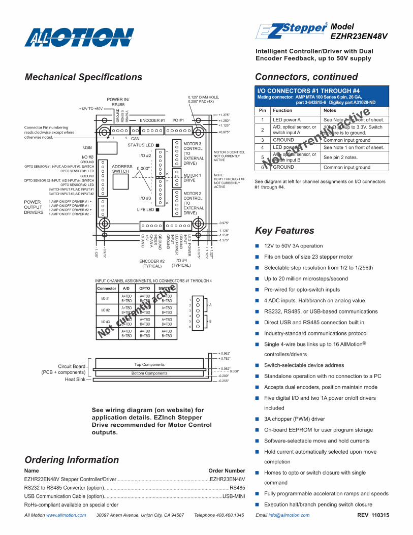
Mechanical Specifications Connectors, continued
I/O COnnECtORS #1 tHROuGH #4Mating connector: AMP MtA 100 Series 6 pin, 26 GA,
part 3-643815-6 Digikey part A31028-nD
Pin Function notes
1 LED power A See Note 1 on front of sheet.
2 A/D, optical sensor, or switch input A
10k Ω pullup to 3.3V. Switch closure is to ground.
3 GROUND Common input ground4 LED power B See Note 1 on front of sheet.
5 A/D, optical sensor, or switch input B See pin 2 notes.
6 GROUND Common input ground
See diagram at left for channel assignments on I/O connectors #1 through #4.
Ordering Informationname Order numberEZHR23EN48V Stepper Controller/Driver...................................................................EZHR23EN48VRS232 to RS485 Converter (option)..........................................................................................RS485USB Communication Cable (option).....................................................................................USB-MINIRoHs-compliant available on special order
-0.975"
-1.125"
- 0.975"
+ 1.125"
+ 0.975"
- 1.125"
+1.125"+1.250"
+1.375"
-1.250"
+0.975"
-1.375"
+ 1.227"
0.000"
0.125" DIAM HOLE, 0.250" PAD (4X)
1 4
Connector Pin numbering reads clockwise except where otherwise noted.
POWER IN/RS485
CAN
ADDRESS
STATUS LED
LIFE LED
GR
OU
ND
RS4
85 A
RS4
85 B
+12V TO +50V
GR
OU
ND
CH
AN
B+5VC
HA
N A
IND
EX
INPU
TLE
D P
OW
ER
GR
OU
ND
INPU
TLED
POW
ERG
RO
UN
D
ENCODER #1
ENCODER #2(TYPICAL)
OPTO SENSOR #1 INPUT, A/D INPUT #3, SWITCHOPTO SENSOR #1 LED
OPTO SENSOR #2 LEDOPTO SENSOR #2 INPUT, A/D INPUT #4, SWITCH
SWITCH INPUT #1, A/D INPUT #1
I/O #Ø
USB
GROUND
GROUND
SWITCH INPUT #2, A/D INPUT #2
1 AMP ON/OFF DRIVER #1 +1 AMP ON/OFF DRIVER #1 -
1 AMP ON/OFF DRIVER #2 -1 AMP ON/OFF DRIVER #2 +
SWITCH
1 61 6
I/O #4(TYPICAL)
I/O #1
POWER OUTPUTDRIVERS
MOTOR 3 CONTROL(TO EXTERNAL DRIVE)
MOTOR 2 CONTROL(TO EXTERNAL DRIVE)
MOTOR 1 DRIVE
Circuit Board(PCB + components)
Heat Sink
0.000"
1
2
3
4
5
6
A
B
INPUT CHANNEL ASSIGNMENTS, I/O CONNECTORS #1 THROUGH 4
Connector A/D OPTO SWITCH
I/O #1 A=TBDB=TBD
A=TBDB=TBD
A=TBDB=TBD
I/O #2 A=TBDB=TBD
A=TBDB=TBD
A=TBDB=TBD
I/O #3 A=TBDB=TBD
A=TBDB=TBD
A=TBDB=TBD
I/O #4 A=TBDB=TBD
A=TBDB=TBD
A=TBDB=TBD
I/O #2
I/O #3
Not currently active
+ 0.762"
+ 0.062"
-0.200" -0.255"
+ 0.962"
MOTOR 3 CONTROLNOT CURRENTLY ACTIVE
NOTE:I/O #1 THROUGH #4 NOT CURRENTLY ACTIVE
Top Components
Bottom Components
Key Features12V to 50V 3A operation ■Fits on back of size 23 stepper motor ■Selectable step resolution from 1/2 to 1/256th ■Up to 20 million microsteps/second ■Pre-wired for opto-switch inputs ■4 ADC inputs. Halt/branch on analog value ■RS232, RS485, or USB-based communications ■Direct USB and RS485 connection built in ■Industry-standard communications protocol ■Single 4-wire bus links up to 16 AllMotion ■ ®
controllers/drivers
Switch-selectable device address ■Standalone operation with no connection to a PC ■Accepts dual encoders, position maintain mode ■Five digital I/O and two 1A power on/off drivers ■included
3A chopper (PWM) driver ■On-board EEPROM for user program storage ■Software-selectable move and hold currents ■Hold current automatically selected upon move ■completion
Homes to opto or switch closure with single ■command
Fully programmable acceleration ramps and speeds ■Execution halt/branch pending switch closure ■
See wiring diagram (on website) for application details. EZInch Stepper Drive recommended for Motor Control outputs.
not currently active