Embed Size (px)
Citation preview
Proceedings of 2004 JUSFA 2004 Japan - USA Symposium on Flexible Automation
Denver Colorado July 19-21 2004
JL024
INTELLIGENT CAM SYSTEM FOR MANUFACTURING OF DIEMOLD
Hirotoshi Ohtsuka
Oita Industrial Research
Institute 1-4361-10 Takae nishi Oita 870-1117 Japan
(ootukaoita-rigojp)
Yoshiaki Kakino
Iwao Yamaji Atsushi Matsubara
Soichi Ibaraki Kyoto University
Yoshida-honmachi Sakyo-ku Kyoto 606-8501 Japan
Heisaburo Nakagawa
The University of Shiga
Prefecture Hassaka-Cho Hikone Shiga 522-8533 Japan
Susumu Nishida
Manufacturing Technology
Institute Inc 1-3 Nakase Mihama-ku Chiba 261-8501 Japan
Keywords endmilling hardened steel dies and molds cutting force fixed cycle pattern tool life estimation CAM
ABSTRACT
An intelligent CAM system for manufacturing of diemold has been developed by DBM Research Consortium This system allows even inexperienced operators to successfully apply the method of direct endmilling of hardened steel using (AlTi)N-coated micro-grain carbide cutters for pre-finish cutting processes of diemold This system supports process design for rough and intermediate-rough cutting decision of cutting conditions and tool life estimation Fixed cycles such as spiral trochoid and corner machining are fully utilized in the proposed CAM system along with a feed rate adaptation strategy for constant cutting forces They are applied mainly for removing critical regions in the tool path pattern Those regions are characterized by an excessive cutting engagement and excessive cutting force The intelligent CAM system was verified experimentally for rough and intermediate-rough machining in the case of manufacturing a cavity-type mold The system achieved good results with regard to productivity and costs
1 Introduction
The worldwide market for diemold has shown increasing demand for short manufacturing and delivery times as well as low price and high quality In diemold industry the fundamental change of manufacturing diemold has occurred with increasing general availability of (AlTi)N-coated micro-grain carbide endmills[1] They are capable of machining hardened steel of the hardness up to about HRC53 and engender the so-called Hardened
Steel Machining Method in manufacturing diemold which has the potential to significantly reduce the process lead time by either eliminating or reducing ineffective grinding and heat treatment processes Knowledge of appropriate cutting conditions and tool life prediction must be established for such advanced tools to be useful for industrial practice because these tools react very sensitively to unsuitable cutting conditions In other words design of optimal cutting conditions and generation of appropriate CL data become the most difficult problem for machining of hardened steel
Complex and free-formed shape of diemold requires CADCAM software for NC-controlled milling Many commercial CADCAM systems exist for diemold nevertheless most of them can not meet the requirement mentioned above Fundamentally they can only generate tool path patterns using the profile offset method from product geometry For that reason experienced and skillful operators still have to decide cutting conditions that are suitable for the purpose For example there are quite often severe concave contour cuttings which cause a remarkable increase of cutting engagement and cutting forces For such cutting feed rate control must be done by experienced and skillful operators for safety and efficiency It is difficult for inexperienced operators to generate appropriate control programs including process design for diemold production using conventional CADCAM systems
This study constructs an intelligent endmilling system for manufacturing diemold It uses a relatively compact database to determine appropriate cutting conditions It can be smoothly integrated into a CADCAM system Moreover its objective is to enable even an inexperienced operator to apply the method of
direct endmilling of hardened steel with reasonable ease and favorable economic outcomes Furthermore a feed rate adaptation strategy for constant cutting forces based on our previous study is also applied along with appropriately designed fixed cycles for efficient removal of critical regions 2 Construction of Intelligent CAM System 21 Objectives Structures and Limitations
The main objective of the intelligent CAM system is automatic process design and NC program generation for rough and intermediate-rough cutting for small and middle-sized diemold made of hardened steel (this study considers die steel JIS SKD6l which is widely used in Japanrsquos diemold industry) using a radius endmill( (AlTi)N-coated micro-grain carbide) The system can determine the tool diameter and cutting conditions depending upon mathematically-expressed productivity and manufacturing cost criteria
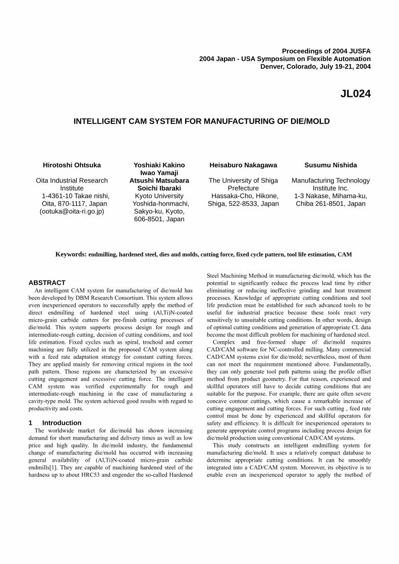
An overviewed flow of the system is shown in Fig 1 First from a 3D CAD model of diemold CL data are produced for a tool candidate by use of commercial CADCAM-software Subsequently a tool path pattern analysis is performed and critical tool path regions are detected geometrically Then fixed cycles such as trochoid milling are applied for removing them For the remaining tool paths the feed rate is adjusted in curved contours to prevent chipping and tool breakage by keeping the cutting forces constant This constant cutting force strategy is also applied for each fixed cycle Next NC programs are generated and the machining time and cost are estimated The entire process design is carried out for different endmill candidates (cutter diameter) Finally the endmill with the most effective result is chosen for use for the actual cutting process
Fig 1 General flow of the intelligent CAM system
The process contains various subsystems and algorithms to realize these functions (a) Tool selection subsystem
This algorithm is intended to select a suitable end mill from candidates based on the material removal ratio and so forth which leads to the lowest time and costs for the desired machining operation (b) Path pattern analysis subsystem
This subsystem detects critical regions geometrically in given tool path patterns There are regions where cutting engagement becomes too large in tool path patterns generated by the profile-offset method such regions may engender high cutting temperature and excessive cutting forces (c) Fixed cycle subsystem
This subsystem inserts fixed cycles on regions where cutting conditions become critical throughout rough and intermediate- rough cutting processes The fixed cycle is a subset of cutting operations that has a certain tool path pattern it is used to remove a certain type of geometric feature such as helical boring spiral milling trochoid milling and corner milling (d) Cutting force estimation subsystem
This subsystem is intended to maintain the average cutting force during the cutting of curved contours by calculating an adjusted feed rate for each tool path to prevent chipping and tool breakage (e) Tool life estimation subsystem
This subsystem estimates the percentage of the tool life of the end mill has already been spent This estimate is calculated based on a database constructed from results of standard cutting tests Our recent study revealed that tool life becomes much shorter when the cutting engagement angle of an end mill is too large even if the constant cutting force strategy is adopted Tool life is estimated depending on cutting conditions with compensation of this effect (f) Cutting time and cost estimation subsystem
This subsystem mathematically estimates the machining time and costs throughout rough and intermediate-rough cutting processes This algorithm determines the most effective process design with lower machining time and costs 22 Cutting Process of DieMold by the system 221 Rough Cutting
In most cases a cavity is more difficult to machine than the core because of its shape Cavity molds are usually rough-cut layer by layer in contour cutting using a radius endmill which has a higher material removal rate compared to a ball endmill of the same diameter Rough cutting starts from an approach hole machined by helical boring and then milling towards the periphery A core mold is also machined layer by layer by starting at the periphery and then milling towards the core shape After one layer is cut the endmill is lowered by an axial depth of cut and the next layer is cut similar to the rough cutting process of the cavity mold 222 Intermediate-Rough Cutting
The objective of the intermediate-rough cutting process is to reduce or eliminate of step-shaped leftover volume that remains after rough cutting It also accelerates the following intermediate and finish cutting processes In most cases it is carried out by a radius endmill Allowance for the following intermediate-finish cutting operation is usually about 1-05mm Intermediate-rough cutting is characterized by an axial depth of cut that is much smaller than that of the rough cutting process However the intermediate-rough cutting process is important from the viewpoint
3D CAD model
Cutting Tool Candidate
Generation of CL DATA (CADCAM system)
Analysis of CL DATA (Detection of Critical Regions)
Application of Fixed Cycles (spiral trochoid corner etc)
Prediction of Cutting Force (Feed rate adaptation for curved contours)
Time and Cost Estimation (Tool Life Prediction)
Generation of NC program
Manufacturing
Cutting Tool Data file
Cutting Conditions Database
of machining time and accuracy of the diemold since it influences the time spent on subsequent intermediate-finish and finish cutting processes Also in the intermediate-rough cutting process the contour cutting is usually used 223 Definition and Types of Fixed Cycles
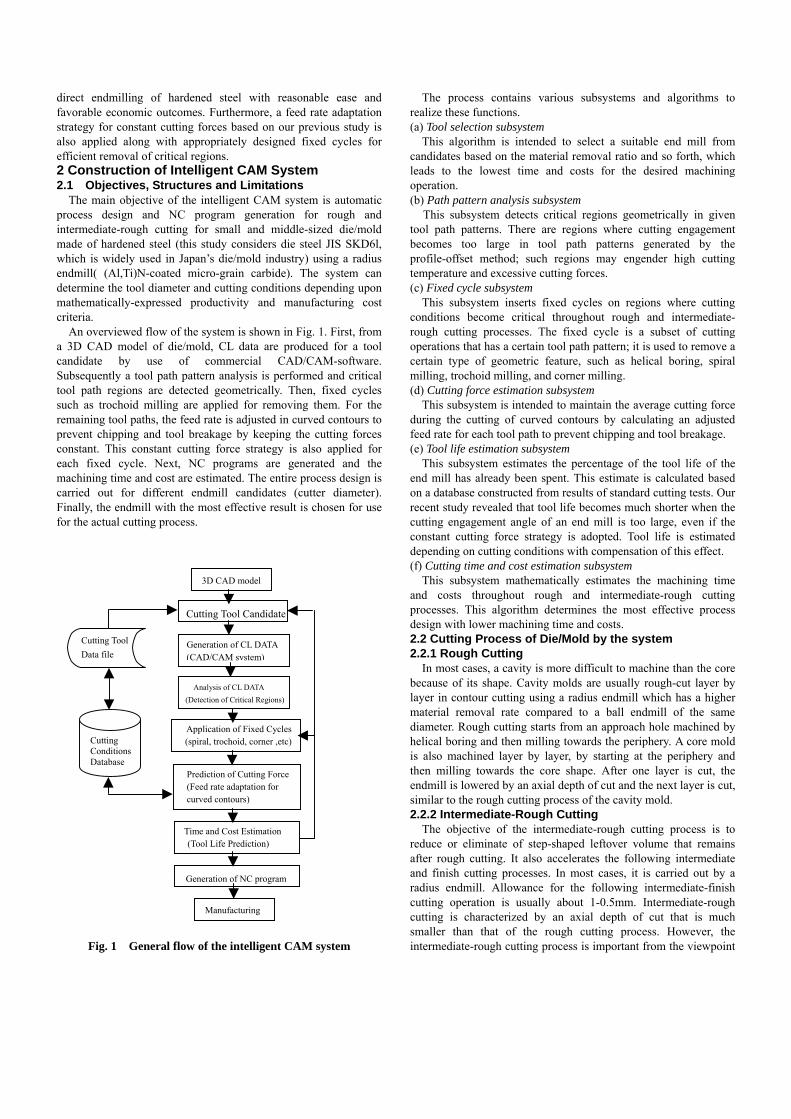
Tool path patterns generated by CADCAM software using the profile offset method for rough and intermediate-rough cutting frequently give localized critical regions for cutting especially for cavity molds It is effective to apply standardized cutting approaches to address this problem The fixed cycle pattern is useful for such a purpose It is often used as pre-cutting for rough cutting For example a simple rectangular pocket can be machined by four prepared fixed cycles as shown in Fig 2 helical boring spiral milling trochoid milling and corner milling Only helical boring used for machining an approach hole for rough cutting process is performed by a ball endmill (Fig 3(a)) In these fixed cycles trochoid slot milling is suitable for removing localized critical regions in the given tool path patterns detected by
Fig 2 Typical fixed cycles for pocketing(Cavity)
(a) Helical boring
(b) Trochoid milling
Fig 3 Schematics of fixed cycles with parameters
(a) parameters (b) Cutting force components
Fig 4 Geometrical relationship for concave contour cutting the path pattern analysis subsystem(Fig 3(b)) Another advantage of this classification is that the process in each fixed cycle can be studied individually Thereby the number of cutting parameters that must be designed simultaneously are reduced to a manageable scale 23 Decision of the Cutting Feed Rate
Selection of a suitable feed rate is a crucial task for cutting of diemold made of hardened steel A critical problem with the cutting of concave contours is increased cutting force Therefore the goal must be to maintain cutting forces at the same level as that in straight cutting This can be accomplished by optimizing the feed rate along the tool path
The basic approach is to predict cutting force while machining and to adjust cutting parameters (eg the feed rate) so that the cutting force becomes constant A second-order cutting force model from our previous work [2] is expressed generally by the following equation
Fxy =β0+β1tm+β2L+β11 tm 2+β22L2+β12 tm L (1)
where Fxy denotes the average cutting force value in XY-plane and tm and L are the maximum undeformed chip thickness and cutting arc length respectively The six coefficients (β0hellip β12) are identified by conducting a set of straight cutting experiments using the least-squares method Fig 4 shows geometric relations associating tm and L for concave contour endmilling For cutting force control a target force Fxy is preset first then the feed rate is solved from the above force model The target force is determined from the standard conditions for straight cutting or industrial recommendation Fig 4 shows that the feed rate must be decreased for smaller tool path contour radius to keep the cutting force constant 24 Estimation of the Tool Life
Tool life estimation provides an important look-ahead capability for diemold manufacturing when considering that tool cost comprises as much as 20 of the total cost of diemode manufacturing In practice it is desired to machine diemold in one single setup with one endmill In this study the total cutting length is used as a measure of tool life and it can be simply assumed that the total cutting length is constant under the feed rate control described in the previous section as the following
(2)
HHeelliiccaall BBoorriinngg SSppiirraall TTrroocchhooiidd Corner
H P Z
D 1
D 2
A1
L 1
L 2
X
Z A2
D
Slot width w
P
CLLi
if ==sum
Point of action(cutting edge)
Fxy
Fy
Fx
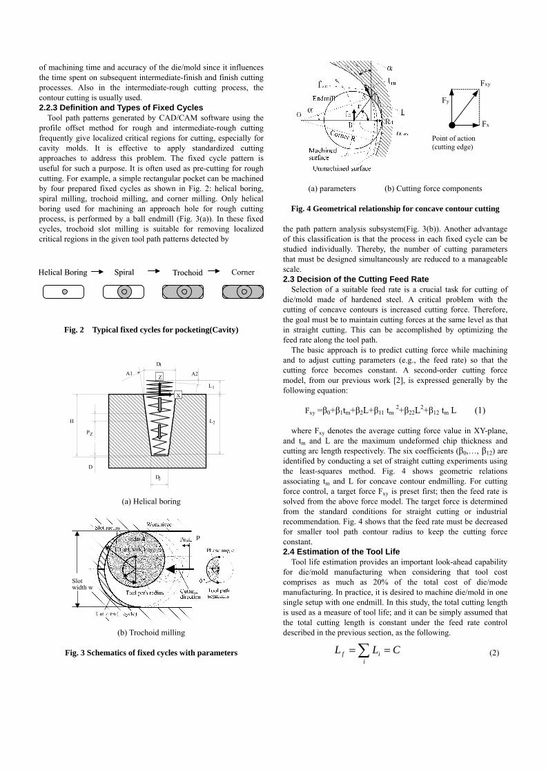
Therein Lf is a measure of tool life as the sum of all the cutting arc lengths Li Nevertheless the validity of this assumption is subject to various constraints The tool life of an endmill becomes very short at the cutting of concave contour in particular when radius ratio Kr(machined surface radiusendmill radius) becomes very small Fig5 shows experimental cutting length against radius ratio Kr As can be seen from this figure cutting length becomes constant for larger radius ratio Kr Incidentally when radius ratio Kr equals to infinity it is equivalent to straight cutting In contrast to that cutting length becomes much shorter when radius ratio Kr is smaller than 20 This short tool life arises from temperature elevation on the endmill at concave contour cutting the time with a cutter engaged in the cutting increases concomitant with the cutting engagement angle(αen in Fig 4(a)) The increased time engenders large temperature elevation on the endmill cutter and consequently a high rate of tool wear As an intermittent cutting process the end milling process has a thermal mechanism that periodically repeats the cycle of heating under cutting and cooling under non-cutting Our recent study shows that tool life becomes also much shorter with increasing cutting engagement angle even if a constant cutting force strategy is adopted The tool wear rate appears to be greatly affected by the cutting engagement angle
Considering this thermal effect on the tool wear rate for diemold cutting the tool life model (2) must be modified as the following
(3)
In that equation γ the correction coefficient is governed by the engagement angle αen Another study by the authors has shown that the flank surface temperature of the worn cutting edge rose sharply at engagement angles larger than 40˚ This fact concurs with the sharp drop in tool life when radius ratio Kr is smaller than 20 as seen in Fig5 Therefore the region subject to such a high cutting engagement angle must be avoided or be removed first by additional tool paths using fixed cycles By integrating the total cutting length Lt along the tool path one can estimate the consumption of tool life at any given point using the ratio of Lt to Lf
Fig 5 Relation between radius ratio Kr and tool life in endmilling concave contour
25 Detection of Critical Regions in the Tool Path Pattern As described in the previous sections trochoid milling is a fixed
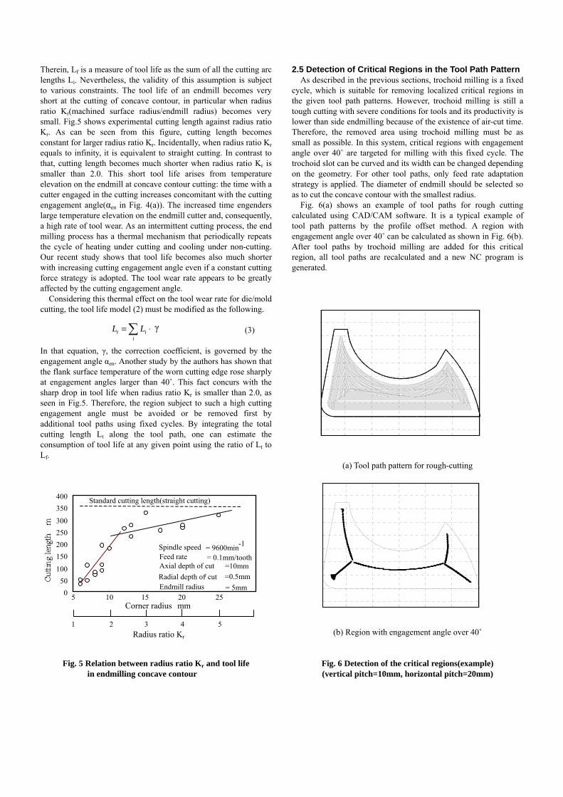
cycle which is suitable for removing localized critical regions in the given tool path patterns However trochoid milling is still a tough cutting with severe conditions for tools and its productivity is lower than side endmilling because of the existence of air-cut time Therefore the removed area using trochoid milling must be as small as possible In this system critical regions with engagement angle over 40˚ are targeted for milling with this fixed cycle The trochoid slot can be curved and its width can be changed depending on the geometry For other tool paths only feed rate adaptation strategy is applied The diameter of endmill should be selected so as to cut the concave contour with the smallest radius
Fig 6(a) shows an example of tool paths for rough cutting calculated using CADCAM software It is a typical example of tool path patterns by the profile offset method A region with engagement angle over 40˚ can be calculated as shown in Fig 6(b) After tool paths by trochoid milling are added for this critical region all tool paths are recalculated and a new NC program is generated
(a) Tool path pattern for rough-cutting
(b) Region with engagement angle over 40˚
Fig 6 Detection of the critical regions(example) (vertical pitch=10mm horizontal pitch=20mm)
0 50
100 150 200 250 300 350 400
Radius ratio Kr
Standard cutting length(straight cutting)
Spindle speed = 9600min -1
Feed rate
Axial depth of cut =10mmRadial depth of cut =05mm
1 2 3 4 5
Corner radius mm 5 10 15 20 25
= 5mmEndmill radius
= 01mmtooth
sdot=sumi
it LL γ
20 40 60 80 100 120
-10
0
10
20
30
40
50
60
70
X mm
Y mm
20 40 60 80 100 120
-10
0
10
20
30
40
50
60
70
x mm
y mm
1223
726
285
360
(mm)
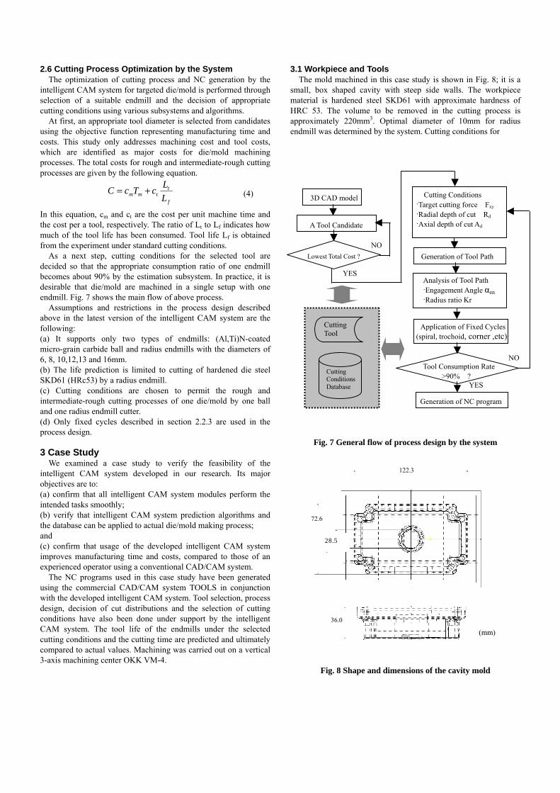
26 Cutting Process Optimization by the System The optimization of cutting process and NC generation by the
intelligent CAM system for targeted diemold is performed through selection of a suitable endmill and the decision of appropriate cutting conditions using various subsystems and algorithms
At first an appropriate tool diameter is selected from candidates using the objective function representing manufacturing time and costs This study only addresses machining cost and tool costs which are identified as major costs for diemold machining processes The total costs for rough and intermediate-rough cutting processes are given by the following equation
(4)
In this equation cm and ct are the cost per unit machine time and the cost per a tool respectively The ratio of Lt to Lf indicates how much of the tool life has been consumed Tool life Lf is obtained from the experiment under standard cutting conditions
As a next step cutting conditions for the selected tool are decided so that the appropriate consumption ratio of one endmill becomes about 90 by the estimation subsystem In practice it is desirable that diemold are machined in a single setup with one endmill Fig 7 shows the main flow of above process Assumptions and restrictions in the process design described above in the latest version of the intelligent CAM system are the following (a) It supports only two types of endmills (AlTi)N-coated micro-grain carbide ball and radius endmills with the diameters of 6 8 101213 and 16mm (b) The life prediction is limited to cutting of hardened die steel SKD61 (HRc53) by a radius endmill (c) Cutting conditions are chosen to permit the rough and intermediate-rough cutting processes of one diemold by one ball and one radius endmill cutter (d) Only fixed cycles described in section 223 are used in the process design 3 Case Study
We examined a case study to verify the feasibility of the intelligent CAM system developed in our research Its major objectives are to (a) confirm that all intelligent CAM system modules perform the intended tasks smoothly (b) verify that intelligent CAM system prediction algorithms and the database can be applied to actual diemold making process and (c) confirm that usage of the developed intelligent CAM system improves manufacturing time and costs compared to those of an experienced operator using a conventional CADCAM system
The NC programs used in this case study have been generated using the commercial CADCAM system TOOLS in conjunction with the developed intelligent CAM system Tool selection process design decision of cut distributions and the selection of cutting conditions have also been done under support by the intelligent CAM system The tool life of the endmills under the selected cutting conditions and the cutting time are predicted and ultimately compared to actual values Machining was carried out on a vertical 3-axis machining center OKK VM-4
31 Workpiece and Tools The mold machined in this case study is shown in Fig 8 it is a
small box shaped cavity with steep side walls The workpiece material is hardened steel SKD61 with approximate hardness of HRC 53 The volume to be removed in the cutting process is approximately 220mm3 Optimal diameter of 10mm for radius endmill was determined by the system Cutting conditions for
Fig 7 General flow of process design by the system
Fig 8 Shape and dimensions of the cavity mold
f
ttmm L
LcTcC +=3D CAD model
A Tool Candidate
Cutting Conditions Target cutting force Fxy
Radial depth of cut Rd Axial depth of cut Ad
Application of Fixed Cycles(spiral trochoid corner etc)
Analysis of Tool Path Engagement Angle αen Radius ratio Kr
Tool Consumption Rate gt90
Generation of NC program
Cutting Tool
Cutting Conditions Database
Generation of Tool Path Lowest Total Cost
NO
NO
YES
YES
Fig 9 Tool paths for rough cutting (with trochoid tool path
added for critical regions) Fig 10 Machined workpiece after rough and intermediate- rough cutting
Table 1 Case study results Intelligent
CAM System Conventional CADCAM (TOOLS)
Cutting length (m) 5607 15390
Cutting time (min) (Predicted cutting time)
3351 (2527)
4247
Time required for (min) programming(approx)
6000
3000
Removal ratio ( mm3min) 663 521
Tool wear
normal wear VB=004mm
normal wear VB=01mm chipping(small)
rough cutting and other cutting processes with their tool path patterns are also decided For example standard cutting conditions for rough cutting are the following with tool path patterns shown in Fig9 spindle speed=4800rpm feed rate=01mmcutter radial depth of cut=05mm axial depth of cut =10mm and so force This figure shows that the axial depth of cut for rough cutting was divided into four layers the critical region detected in the deepest layer machined by trochoid milling differs greatly from that in the first layer
For comparison another cutting condition and tool paths using only a ball endmill were determined by an experienced operator using a conventional CADCAM system It is conventionally a standard way machining of small and middle-sized diemold is usually done using a ball endmill In this case standard cutting conditions using a ball endmill with a 5 mm radius(2 flutes) for rough cutting are spindle speed=4800rpm feed rate=005mm cutter radial depth of cut=35mm axial depth of cut =06mm and so forth 32 Machining Results
Table 1 shows the obtained results of rough and intermediate -rough machining processes Machining of the cavity mold was carried out with just one ball endmill and one radius endmill As shown in this table cutting time was reduced by 20 and removal ratio was increased by 27 over the conventional method The actual cutting time was longer by 35 compared to predicted time by the system mostly because the commanded feed rate cannot be achieved at corners because of servo delay The conventional scheme allowed longer cutting length because it requires machining of 58 layers with a small axial depth of cut After rough and intermediate-rough machining by the intelligent CAM system normal flank wear(VB=004mm) was observed at the cutting edge with no serious failure which proved clearly the validity of the developed cutting condition database and the effectiveness of an integrated system including the fixed cycle of trochoid milling 4 Conclusions
An intelligent CAM system for manufacturing diemold was developed A cutting condition database for endmilling hardened steel by (AlTi)N-coated micro-grain carbide cutters was also developed based on cutting experiment results This integrated system allows an inexperienced operator to apply the method of direct endmilling of hardened steel successfully It supports process design and decision of cutting conditions for rough and intermediate-rough cutting processes in conjunction with integrated subsystems such as feed rate adaptation tool life estimation and others Results of the case study for machining a box-shaped cavity mold validated the productivity improvements of the developed system with the database over that of the conventional method References
1 YamadaY et al High Speed Cutting Performance of (AlTi)N-coated carbide endmills Proceedings of the International Conference on Progress of Cutting and Grinding 1996(ICPCG-96) Vol3 pp2111996
2 Kakino Y et al NC Programming for Constant Cutting Force in Die Machining Proceedings of the International Conference on Advanced Manufacturing System and Manufacturing Automation 2000pp471 2000
20mm (b) 4th layer (deepest layer)
(a) First layer 20mm
direct endmilling of hardened steel with reasonable ease and favorable economic outcomes Furthermore a feed rate adaptation strategy for constant cutting forces based on our previous study is also applied along with appropriately designed fixed cycles for efficient removal of critical regions 2 Construction of Intelligent CAM System 21 Objectives Structures and Limitations
The main objective of the intelligent CAM system is automatic process design and NC program generation for rough and intermediate-rough cutting for small and middle-sized diemold made of hardened steel (this study considers die steel JIS SKD6l which is widely used in Japanrsquos diemold industry) using a radius endmill( (AlTi)N-coated micro-grain carbide) The system can determine the tool diameter and cutting conditions depending upon mathematically-expressed productivity and manufacturing cost criteria
An overviewed flow of the system is shown in Fig 1 First from a 3D CAD model of diemold CL data are produced for a tool candidate by use of commercial CADCAM-software Subsequently a tool path pattern analysis is performed and critical tool path regions are detected geometrically Then fixed cycles such as trochoid milling are applied for removing them For the remaining tool paths the feed rate is adjusted in curved contours to prevent chipping and tool breakage by keeping the cutting forces constant This constant cutting force strategy is also applied for each fixed cycle Next NC programs are generated and the machining time and cost are estimated The entire process design is carried out for different endmill candidates (cutter diameter) Finally the endmill with the most effective result is chosen for use for the actual cutting process
Fig 1 General flow of the intelligent CAM system
The process contains various subsystems and algorithms to realize these functions (a) Tool selection subsystem
This algorithm is intended to select a suitable end mill from candidates based on the material removal ratio and so forth which leads to the lowest time and costs for the desired machining operation (b) Path pattern analysis subsystem
This subsystem detects critical regions geometrically in given tool path patterns There are regions where cutting engagement becomes too large in tool path patterns generated by the profile-offset method such regions may engender high cutting temperature and excessive cutting forces (c) Fixed cycle subsystem
This subsystem inserts fixed cycles on regions where cutting conditions become critical throughout rough and intermediate- rough cutting processes The fixed cycle is a subset of cutting operations that has a certain tool path pattern it is used to remove a certain type of geometric feature such as helical boring spiral milling trochoid milling and corner milling (d) Cutting force estimation subsystem
This subsystem is intended to maintain the average cutting force during the cutting of curved contours by calculating an adjusted feed rate for each tool path to prevent chipping and tool breakage (e) Tool life estimation subsystem
This subsystem estimates the percentage of the tool life of the end mill has already been spent This estimate is calculated based on a database constructed from results of standard cutting tests Our recent study revealed that tool life becomes much shorter when the cutting engagement angle of an end mill is too large even if the constant cutting force strategy is adopted Tool life is estimated depending on cutting conditions with compensation of this effect (f) Cutting time and cost estimation subsystem
This subsystem mathematically estimates the machining time and costs throughout rough and intermediate-rough cutting processes This algorithm determines the most effective process design with lower machining time and costs 22 Cutting Process of DieMold by the system 221 Rough Cutting
In most cases a cavity is more difficult to machine than the core because of its shape Cavity molds are usually rough-cut layer by layer in contour cutting using a radius endmill which has a higher material removal rate compared to a ball endmill of the same diameter Rough cutting starts from an approach hole machined by helical boring and then milling towards the periphery A core mold is also machined layer by layer by starting at the periphery and then milling towards the core shape After one layer is cut the endmill is lowered by an axial depth of cut and the next layer is cut similar to the rough cutting process of the cavity mold 222 Intermediate-Rough Cutting
The objective of the intermediate-rough cutting process is to reduce or eliminate of step-shaped leftover volume that remains after rough cutting It also accelerates the following intermediate and finish cutting processes In most cases it is carried out by a radius endmill Allowance for the following intermediate-finish cutting operation is usually about 1-05mm Intermediate-rough cutting is characterized by an axial depth of cut that is much smaller than that of the rough cutting process However the intermediate-rough cutting process is important from the viewpoint
3D CAD model
Cutting Tool Candidate
Generation of CL DATA (CADCAM system)
Analysis of CL DATA (Detection of Critical Regions)
Application of Fixed Cycles (spiral trochoid corner etc)
Prediction of Cutting Force (Feed rate adaptation for curved contours)
Time and Cost Estimation (Tool Life Prediction)
Generation of NC program
Manufacturing
Cutting Tool Data file
Cutting Conditions Database
of machining time and accuracy of the diemold since it influences the time spent on subsequent intermediate-finish and finish cutting processes Also in the intermediate-rough cutting process the contour cutting is usually used 223 Definition and Types of Fixed Cycles
Tool path patterns generated by CADCAM software using the profile offset method for rough and intermediate-rough cutting frequently give localized critical regions for cutting especially for cavity molds It is effective to apply standardized cutting approaches to address this problem The fixed cycle pattern is useful for such a purpose It is often used as pre-cutting for rough cutting For example a simple rectangular pocket can be machined by four prepared fixed cycles as shown in Fig 2 helical boring spiral milling trochoid milling and corner milling Only helical boring used for machining an approach hole for rough cutting process is performed by a ball endmill (Fig 3(a)) In these fixed cycles trochoid slot milling is suitable for removing localized critical regions in the given tool path patterns detected by
Fig 2 Typical fixed cycles for pocketing(Cavity)
(a) Helical boring
(b) Trochoid milling
Fig 3 Schematics of fixed cycles with parameters
(a) parameters (b) Cutting force components
Fig 4 Geometrical relationship for concave contour cutting the path pattern analysis subsystem(Fig 3(b)) Another advantage of this classification is that the process in each fixed cycle can be studied individually Thereby the number of cutting parameters that must be designed simultaneously are reduced to a manageable scale 23 Decision of the Cutting Feed Rate
Selection of a suitable feed rate is a crucial task for cutting of diemold made of hardened steel A critical problem with the cutting of concave contours is increased cutting force Therefore the goal must be to maintain cutting forces at the same level as that in straight cutting This can be accomplished by optimizing the feed rate along the tool path
The basic approach is to predict cutting force while machining and to adjust cutting parameters (eg the feed rate) so that the cutting force becomes constant A second-order cutting force model from our previous work [2] is expressed generally by the following equation
Fxy =β0+β1tm+β2L+β11 tm 2+β22L2+β12 tm L (1)
where Fxy denotes the average cutting force value in XY-plane and tm and L are the maximum undeformed chip thickness and cutting arc length respectively The six coefficients (β0hellip β12) are identified by conducting a set of straight cutting experiments using the least-squares method Fig 4 shows geometric relations associating tm and L for concave contour endmilling For cutting force control a target force Fxy is preset first then the feed rate is solved from the above force model The target force is determined from the standard conditions for straight cutting or industrial recommendation Fig 4 shows that the feed rate must be decreased for smaller tool path contour radius to keep the cutting force constant 24 Estimation of the Tool Life
Tool life estimation provides an important look-ahead capability for diemold manufacturing when considering that tool cost comprises as much as 20 of the total cost of diemode manufacturing In practice it is desired to machine diemold in one single setup with one endmill In this study the total cutting length is used as a measure of tool life and it can be simply assumed that the total cutting length is constant under the feed rate control described in the previous section as the following
(2)
HHeelliiccaall BBoorriinngg SSppiirraall TTrroocchhooiidd Corner
H P Z
D 1
D 2
A1
L 1
L 2
X
Z A2
D
Slot width w
P
CLLi
if ==sum
Point of action(cutting edge)
Fxy
Fy
Fx
Therein Lf is a measure of tool life as the sum of all the cutting arc lengths Li Nevertheless the validity of this assumption is subject to various constraints The tool life of an endmill becomes very short at the cutting of concave contour in particular when radius ratio Kr(machined surface radiusendmill radius) becomes very small Fig5 shows experimental cutting length against radius ratio Kr As can be seen from this figure cutting length becomes constant for larger radius ratio Kr Incidentally when radius ratio Kr equals to infinity it is equivalent to straight cutting In contrast to that cutting length becomes much shorter when radius ratio Kr is smaller than 20 This short tool life arises from temperature elevation on the endmill at concave contour cutting the time with a cutter engaged in the cutting increases concomitant with the cutting engagement angle(αen in Fig 4(a)) The increased time engenders large temperature elevation on the endmill cutter and consequently a high rate of tool wear As an intermittent cutting process the end milling process has a thermal mechanism that periodically repeats the cycle of heating under cutting and cooling under non-cutting Our recent study shows that tool life becomes also much shorter with increasing cutting engagement angle even if a constant cutting force strategy is adopted The tool wear rate appears to be greatly affected by the cutting engagement angle
Considering this thermal effect on the tool wear rate for diemold cutting the tool life model (2) must be modified as the following
(3)
In that equation γ the correction coefficient is governed by the engagement angle αen Another study by the authors has shown that the flank surface temperature of the worn cutting edge rose sharply at engagement angles larger than 40˚ This fact concurs with the sharp drop in tool life when radius ratio Kr is smaller than 20 as seen in Fig5 Therefore the region subject to such a high cutting engagement angle must be avoided or be removed first by additional tool paths using fixed cycles By integrating the total cutting length Lt along the tool path one can estimate the consumption of tool life at any given point using the ratio of Lt to Lf
Fig 5 Relation between radius ratio Kr and tool life in endmilling concave contour
25 Detection of Critical Regions in the Tool Path Pattern As described in the previous sections trochoid milling is a fixed
cycle which is suitable for removing localized critical regions in the given tool path patterns However trochoid milling is still a tough cutting with severe conditions for tools and its productivity is lower than side endmilling because of the existence of air-cut time Therefore the removed area using trochoid milling must be as small as possible In this system critical regions with engagement angle over 40˚ are targeted for milling with this fixed cycle The trochoid slot can be curved and its width can be changed depending on the geometry For other tool paths only feed rate adaptation strategy is applied The diameter of endmill should be selected so as to cut the concave contour with the smallest radius
Fig 6(a) shows an example of tool paths for rough cutting calculated using CADCAM software It is a typical example of tool path patterns by the profile offset method A region with engagement angle over 40˚ can be calculated as shown in Fig 6(b) After tool paths by trochoid milling are added for this critical region all tool paths are recalculated and a new NC program is generated
(a) Tool path pattern for rough-cutting
(b) Region with engagement angle over 40˚
Fig 6 Detection of the critical regions(example) (vertical pitch=10mm horizontal pitch=20mm)
0 50
100 150 200 250 300 350 400
Radius ratio Kr
Standard cutting length(straight cutting)
Spindle speed = 9600min -1
Feed rate
Axial depth of cut =10mmRadial depth of cut =05mm
1 2 3 4 5
Corner radius mm 5 10 15 20 25
= 5mmEndmill radius
= 01mmtooth
sdot=sumi
it LL γ
20 40 60 80 100 120
-10
0
10
20
30
40
50
60
70
X mm
Y mm
20 40 60 80 100 120
-10
0
10
20
30
40
50
60
70
x mm
y mm
1223
726
285
360
(mm)
26 Cutting Process Optimization by the System The optimization of cutting process and NC generation by the
intelligent CAM system for targeted diemold is performed through selection of a suitable endmill and the decision of appropriate cutting conditions using various subsystems and algorithms
At first an appropriate tool diameter is selected from candidates using the objective function representing manufacturing time and costs This study only addresses machining cost and tool costs which are identified as major costs for diemold machining processes The total costs for rough and intermediate-rough cutting processes are given by the following equation
(4)
In this equation cm and ct are the cost per unit machine time and the cost per a tool respectively The ratio of Lt to Lf indicates how much of the tool life has been consumed Tool life Lf is obtained from the experiment under standard cutting conditions
As a next step cutting conditions for the selected tool are decided so that the appropriate consumption ratio of one endmill becomes about 90 by the estimation subsystem In practice it is desirable that diemold are machined in a single setup with one endmill Fig 7 shows the main flow of above process Assumptions and restrictions in the process design described above in the latest version of the intelligent CAM system are the following (a) It supports only two types of endmills (AlTi)N-coated micro-grain carbide ball and radius endmills with the diameters of 6 8 101213 and 16mm (b) The life prediction is limited to cutting of hardened die steel SKD61 (HRc53) by a radius endmill (c) Cutting conditions are chosen to permit the rough and intermediate-rough cutting processes of one diemold by one ball and one radius endmill cutter (d) Only fixed cycles described in section 223 are used in the process design 3 Case Study
We examined a case study to verify the feasibility of the intelligent CAM system developed in our research Its major objectives are to (a) confirm that all intelligent CAM system modules perform the intended tasks smoothly (b) verify that intelligent CAM system prediction algorithms and the database can be applied to actual diemold making process and (c) confirm that usage of the developed intelligent CAM system improves manufacturing time and costs compared to those of an experienced operator using a conventional CADCAM system
The NC programs used in this case study have been generated using the commercial CADCAM system TOOLS in conjunction with the developed intelligent CAM system Tool selection process design decision of cut distributions and the selection of cutting conditions have also been done under support by the intelligent CAM system The tool life of the endmills under the selected cutting conditions and the cutting time are predicted and ultimately compared to actual values Machining was carried out on a vertical 3-axis machining center OKK VM-4
31 Workpiece and Tools The mold machined in this case study is shown in Fig 8 it is a
small box shaped cavity with steep side walls The workpiece material is hardened steel SKD61 with approximate hardness of HRC 53 The volume to be removed in the cutting process is approximately 220mm3 Optimal diameter of 10mm for radius endmill was determined by the system Cutting conditions for
Fig 7 General flow of process design by the system
Fig 8 Shape and dimensions of the cavity mold
f
ttmm L
LcTcC +=3D CAD model
A Tool Candidate
Cutting Conditions Target cutting force Fxy
Radial depth of cut Rd Axial depth of cut Ad
Application of Fixed Cycles(spiral trochoid corner etc)
Analysis of Tool Path Engagement Angle αen Radius ratio Kr
Tool Consumption Rate gt90
Generation of NC program
Cutting Tool
Cutting Conditions Database
Generation of Tool Path Lowest Total Cost
NO
NO
YES
YES
Fig 9 Tool paths for rough cutting (with trochoid tool path
added for critical regions) Fig 10 Machined workpiece after rough and intermediate- rough cutting
Table 1 Case study results Intelligent
CAM System Conventional CADCAM (TOOLS)
Cutting length (m) 5607 15390
Cutting time (min) (Predicted cutting time)
3351 (2527)
4247
Time required for (min) programming(approx)
6000
3000
Removal ratio ( mm3min) 663 521
Tool wear
normal wear VB=004mm
normal wear VB=01mm chipping(small)
rough cutting and other cutting processes with their tool path patterns are also decided For example standard cutting conditions for rough cutting are the following with tool path patterns shown in Fig9 spindle speed=4800rpm feed rate=01mmcutter radial depth of cut=05mm axial depth of cut =10mm and so force This figure shows that the axial depth of cut for rough cutting was divided into four layers the critical region detected in the deepest layer machined by trochoid milling differs greatly from that in the first layer
For comparison another cutting condition and tool paths using only a ball endmill were determined by an experienced operator using a conventional CADCAM system It is conventionally a standard way machining of small and middle-sized diemold is usually done using a ball endmill In this case standard cutting conditions using a ball endmill with a 5 mm radius(2 flutes) for rough cutting are spindle speed=4800rpm feed rate=005mm cutter radial depth of cut=35mm axial depth of cut =06mm and so forth 32 Machining Results
Table 1 shows the obtained results of rough and intermediate -rough machining processes Machining of the cavity mold was carried out with just one ball endmill and one radius endmill As shown in this table cutting time was reduced by 20 and removal ratio was increased by 27 over the conventional method The actual cutting time was longer by 35 compared to predicted time by the system mostly because the commanded feed rate cannot be achieved at corners because of servo delay The conventional scheme allowed longer cutting length because it requires machining of 58 layers with a small axial depth of cut After rough and intermediate-rough machining by the intelligent CAM system normal flank wear(VB=004mm) was observed at the cutting edge with no serious failure which proved clearly the validity of the developed cutting condition database and the effectiveness of an integrated system including the fixed cycle of trochoid milling 4 Conclusions
An intelligent CAM system for manufacturing diemold was developed A cutting condition database for endmilling hardened steel by (AlTi)N-coated micro-grain carbide cutters was also developed based on cutting experiment results This integrated system allows an inexperienced operator to apply the method of direct endmilling of hardened steel successfully It supports process design and decision of cutting conditions for rough and intermediate-rough cutting processes in conjunction with integrated subsystems such as feed rate adaptation tool life estimation and others Results of the case study for machining a box-shaped cavity mold validated the productivity improvements of the developed system with the database over that of the conventional method References
1 YamadaY et al High Speed Cutting Performance of (AlTi)N-coated carbide endmills Proceedings of the International Conference on Progress of Cutting and Grinding 1996(ICPCG-96) Vol3 pp2111996
2 Kakino Y et al NC Programming for Constant Cutting Force in Die Machining Proceedings of the International Conference on Advanced Manufacturing System and Manufacturing Automation 2000pp471 2000
20mm (b) 4th layer (deepest layer)
(a) First layer 20mm
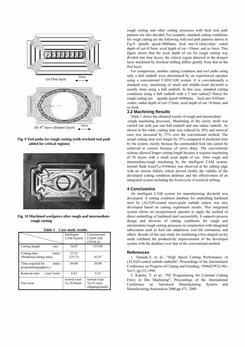