Embed Size (px)
Citation preview
1
Intellicus Cluster and Load
Balancing- Linux Version: 16.0

2
Copyright © 2017 Intellicus Technologies
This document and its content is copyrighted material of Intellicus Technologies.
The content may not be copied or derived from, through any means, in parts or in whole, without a prior
written permission from Intellicus Technologies. All other product names are believed to be registered
trademarks of the respective companies.
Dated: August 2017
Acknowledgements
Intellicus acknowledges using of third-party libraries to extend support to the functionalities that they
provide.
For details, visit: http://www.intellicus.com/acknowledgements.htm

3
Contents
1 Introduction 4
Introduction to Intellicus Clustering 4
2 Architecture & Component Description 5
Architecture Diagram 5
Components 5
3 Prerequisites 7
Prerequisites for Installing Intellicus Report Server Cluster 7
4 Installation and Configuration 8
Setting up NFS 8
Installing Report Server Node 9
Configuring Report Server Node 9
Installing Load Balancer Component 12
Configuring Load Balancer 12
Installing Cluster Java Portal setup 16
Configuring each of the Cluster Report Servers 16
Running Sequence 18
5 Load Balancer page on Portal 19
Cluster Nodes (Report Servers) 19
Load Balancers 20
Settings 21

4
1 Introduction
Introduction to Intellicus Clustering
Intellicus BI server is a high performance platform for service Enterprise BI needs. The report server
component is the heavy duty performer that processes data and renders pages, grids and charts. Report
server is architected to efficiently utilize allocated resources – RAM, Disk and CPU from the given machine. It
is fully multi-threaded and designed to provide concurrent reporting functionality to hundreds of
simultaneous users.
When the demand for concurrency increases, first option to scale is to allocate more resources to Intellicus
report server. Allocation of resources on a single machine may reach certain limitation.
On an enterprise production reporting scenario, the need of high availability of BI server is essential. This
requires failover mechanism.
To achieve extended scalability and high availability of Intellicus BI infrastructure, you can install Intellicus
report servers on multiple machines to form a cluster and configure load balancing and failover.
Intellicus report server cluster is assisted by a light weight component – Intellicus load balancer, which is
primarily responsible for heart beat gathering and load distribution.
5
2 Architecture & Component Description
Architecture Diagram
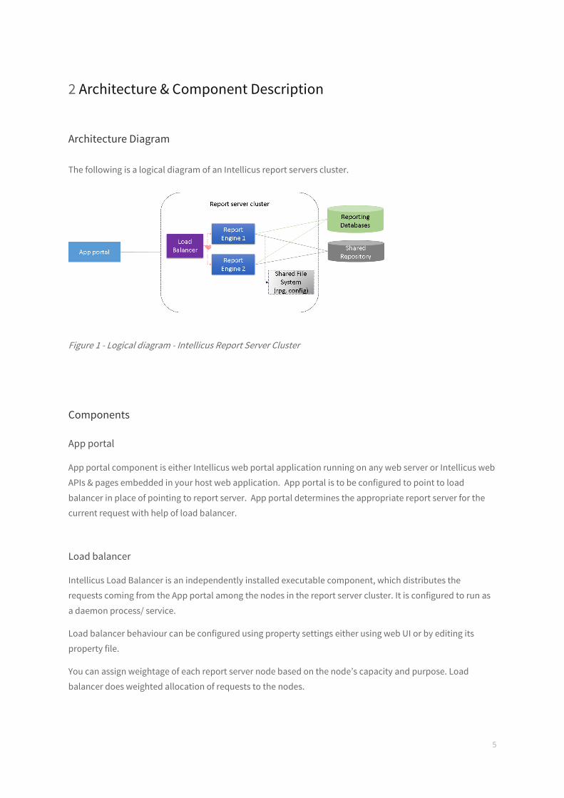
The following is a logical diagram of an Intellicus report servers cluster.
Figure 1 - Logical diagram - Intellicus Report Server Cluster
Components
App portal
App portal component is either Intellicus web portal application running on any web server or Intellicus web
APIs & pages embedded in your host web application. App portal is to be configured to point to load
balancer in place of pointing to report server. App portal determines the appropriate report server for the
current request with help of load balancer.
Load balancer
Intellicus Load Balancer is an independently installed executable component, which distributes the
requests coming from the App portal among the nodes in the report server cluster. It is configured to run as
a daemon process/ service.
Load balancer behaviour can be configured using property settings either using web UI or by editing its
property file.
You can assign weightage of each report server node based on the node’s capacity and purpose. Load
balancer does weighted allocation of requests to the nodes.
6
Note: You can install more than one load balancer components in your cluster to
support load balancer failover.
Report Server (node)
Report server node has all the software runnable installed on its own machine and the key folders pointed
to a shared file system. It performs all reporting operations as a standalone report server except of all
common configuration files – namely connection files, style templates, language bundles, property files and
persisted storage – namely published reports folder(rpg), report data cache, etc.
All report server nodes connect to same repository database. Any report object saved/deployed on the
cluster will be immediately available to all nodes of the cluster.
Report server node communicates its current load information and health to the load balancer component
at a regular interval.
Shared File System
Intellicus Report Servers cluster shares a file system for common persisted storage and common
configuration files. The shared file system can be made available using a NFS or a shared folder mounted on
other nodes. We recommend sufficient iops be available to cater to all the report servers to read and write
data to this Shared File System.
Note: Shared file System is the single point of failure in an Intellicus report
server cluster. It is strongly recommended that you ensure highly available, fail-
proof RAID systems supporting the Shared File System.
Shared Repository
All nodes on a report server cluster connect to same Intellicus repository and share all report objects
seamlessly.
Note: Shared repository database is the single point of failure.
It is strongly recommended that you ensure it is highly available by database
replication systems.
Reporting databases
All nodes on a report server cluster connect to same reporting databases. The database schema is
configured to fetch only once and shared by all nodes.
7
3 Prerequisites
Prerequisites for Installing Intellicus Report Server Cluster
Following information needs to be kept handy before beginning Installation of Intellicus Report Server
Cluster:
Shared File System - that can be mounted on all the report server node machines.
High speed network access from machines with high IOPS
Machines identified for installing Intellicus report server node (Two or more)
10-20GB RAM available for report server process
IP address, Server port number, resources (RAM, CPUs) for setting weightage
Packages – gunzip
Appropriate rights to do chmod, to mount the NFS (or NFS already mounted)
Machines identified for installing Load Balancers component (One or more)
1 GB RAM available for load balancer process
IP Address, balancer port number
Packages - gunzip
Note: Load balancer is a light weight component and the machine identified could be
same as App portal machine or report server node machine.
Machines identified on which Intellicus clients APIs or App portal will be installed
Repository database – must be a multi user database system (Mysql, PostGreSQL, OracleDB etc.)
IP Address, Server port, Report data user credentials
8
4 Installation and Configuration
Setting up NFS
Configuring directory structure on the Shared File System
The Shared File System needs to have a set of directories and config files that shall be used by all the report
server nodes. To create the required directory structure, a compressed file is shipped to you, which is to be
extracted at the designated shared file system path.
Steps:
Copy the files to a target location on shared file system:
1) IntellicusShared7.x_ux64.tar.gz
2) InstallSharedIntellicus7.x_ux64.sh
Run InstallSharedIntellicus7.x_ux64.sh to extract the folder structure from IntellicusShared7.x_ux64.tar.gz
Syntax:
./InstallSharedIntellicus7.x_ux64.sh
The InstallSharedIntellicus7.x_ux64.sh has ungzip commands to extract the folder structure at the same
location where IntellicusShared7.x_ux64.tar.gz was placed.
After successful extraction, your list (ls) command would show a structure as per below image.
Verify that user and the group has read and write (rw) access on this extracted folder structure.
Sharing and mounting
The Intellicus Shared folder created above on Shared File System (on NFS) needs to be shared for mounting
on all the cluster nodes.
Open /etc/exports file on the file system sharing machine
Make the sharing entry as
<exportdirectory> <host><options>
Example:
installpath/IntellicusShared 192.168.1.100(rw,no_root_squash,async)
Starting NFS services
The NFS service needs to be started to activate.
9
On RedHat
Use following commands to start NFS services in RedHat
service nfs start service portmap start
On SUSE
Use the following command to start NFS services in SUSE
rcnfs start
Installing Report Server Node
Intellicus report server node software has binaries, libraries, configurations and local temporary storage
structures.
To install a node, a compressed file is shipped to you, which needs to be extracted at the target location on
the report server node machine.
Steps:
Copy the files to a target location on shared file system:
1) IntellicusClusterNode7.x_ux64.tar.gz
2) InstallIntellicusClusterNode7.x_ux64.sh
Run InstallIntellicusClusterNode7.x_ux64.sh to extract the folder structure from
IntellicusClusterNode7.x_ux64.tar.gz
Syntax:
./InstallIntellicusClusterNode7.x_ux64.sh
After successful extraction, your list (ls) command would show a structure as per below image.
For each node you must repeat the steps (4.2 & 4.3) on those nodes.
Configuring Report Server Node
Configuring a report server node has following steps:
1. Map host names to IP Addresses
2. Mount Shared File System Path on local machine
3. Configure Shared File System Path
4. Configuring network, scheduler and other properties of report server node
10
Map host names to IP Addresses
This step is generally completed by IT teams in any network system. You can verify that database machines,
NFS are mapped, so that IP addresses can be interchangeably used with machine host names.
Mount Shared File System Path on local machine
It is essential that the Shared File System path is mounted and available on the node server, before the
report server boots to run.
We recommend that the mount command is added in boot scripts of the node server machine.
Alternatively, the mount command can be put inside Intellicus start script and Intellicus script be added to
boot script.
Syntax:
Create a directory on the local node server machine to mount Intellicus Shared File System folder.
mkdir /user/IntellicusShared
mount the directory
mount -t nfs <NFS IP address>:/<NFSInstallPath/IntellicusShared> /user/IntellicusShared
Configure Shared File System Path
Report Server node saves the Shared File System path in cluster.properties file.
On Linux, we provide a shell script to prompt you to enter the mounted directory path on the console.
Syntax:
In the directory, go to /<installpath>/IntellicusCluster
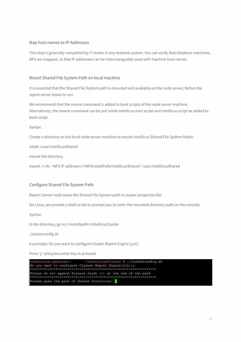
./clusterconfig.sh
It prompts: Do you want to configure Cluster Report Engine (y/n):
Press ‘y’ and press enter key to proceed.
It prompts: Please pass the path of Shared Intellicus:
Type /user/IntellicusShared or equivalent mount path you have configured and press enter.
Do not suffix the path with a closing /
11
Configure network, scheduler and other properties of report server node
Each report server node can be further configured for the node level behaviour. This includes letting the
node know the path of shared file system directory, network port etc.
These properties are configured by editing the cluster.properties present in [Install
Path]/ClusterReportEngine/cluster
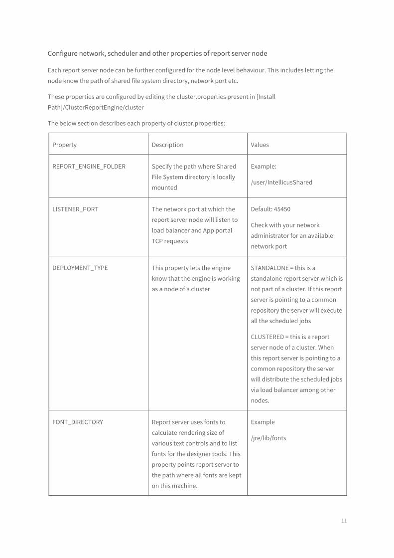
The below section describes each property of cluster.properties:
Property Description Values
REPORT_ENGINE_FOLDER Specify the path where Shared
File System directory is locally
mounted
Example:
/user/IntellicusShared
LISTENER_PORT The network port at which the
report server node will listen to
load balancer and App portal
TCP requests
Default: 45450
Check with your network
administrator for an available
network port
DEPLOYMENT_TYPE This property lets the engine
know that the engine is working
as a node of a cluster
STANDALONE = this is a
standalone report server which is
not part of a cluster. If this report
server is pointing to a common
repository the server will execute
all the scheduled jobs
CLUSTERED = this is a report
server node of a cluster. When
this report server is pointing to a
common repository the server
will distribute the scheduled jobs
via load balancer among other
nodes.
FONT_DIRECTORY Report server uses fonts to
calculate rendering size of
various text controls and to list
fonts for the designer tools. This
property points report server to
the path where all fonts are kept
on this machine.
Example
/jre/lib/fonts
12
LOG Report server writes application
logs at this mentioned path
Example
../logs
Installing Load Balancer Component
Intellicus Load Balancer is shipped as a tar file. This file is generally named as
IntellicusLoadBalancer.x.tar.gz
For example, IntellicusLoadBalancerLinux_64Bit_ 6.1.1.tar.gz
Copy the tar.gz to the desired directory location on machine identified for installing Load Balancer
Load balancer can be co-installed either on app portal machine or one of the report server nodes or can be
installed on a separate machine.
Syntax:
Un-tar the file using below command
tar -zxvf IntellicusLoadBalancerLinux_64Bit_ 6.1.1.tar.gz
This process will create directory structure ‘Intellicus/LoadBalancer’ and copies the Load Balancer software
files inside it.
Load balancer component can be started using runLB.sh under Intellicus/LoadBalancer/bin/.
Load Balancer can be stopped using shutdownLB.sh under Intellicus/LoadBalancer/bin/.
Configuring Load Balancer
Load balancer is responsible for distributing the incoming report view requests among the nodes of report
server cluster based on load, health and weightage ratio. Load balancer checks the heartbeat of all the
nodes of the cluster to diagnose their health.
Load balancer itself can be installed in multiple, for fail-over in this layer.
A load balancer is configured with the addresses of report server nodes of the cluster that it will manage.
Optionally it is also configured with secondary load balancer addresses for fail-over.
Configuring a load balancer has following steps:
1. Map host names to IP Addresses
2. Configuring Load balancer component properties
3. Configure report server node addresses and their weightage
13
4. Configuring secondary load balancer address, if required
5. Configure load balancer algorithm
Map host names to IP addresses
This step is generally completed by IT teams in any network system. You can verify that report server nodes
are mapped, so that IP addresses can be interchangeably used with machine host names.
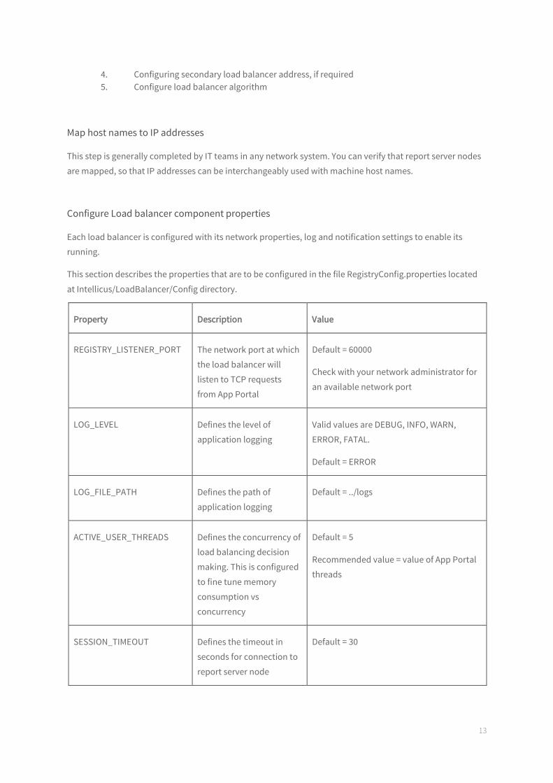
Configure Load balancer component properties
Each load balancer is configured with its network properties, log and notification settings to enable its
running.
This section describes the properties that are to be configured in the file RegistryConfig.properties located
at Intellicus/LoadBalancer/Config directory.
Property Description Value
REGISTRY_LISTENER_PORT The network port at which
the load balancer will
listen to TCP requests
from App Portal
Default = 60000
Check with your network administrator for
an available network port
LOG_LEVEL Defines the level of
application logging
Valid values are DEBUG, INFO, WARN,
ERROR, FATAL.
Default = ERROR
LOG_FILE_PATH Defines the path of
application logging
Default = ../logs
ACTIVE_USER_THREADS Defines the concurrency of
load balancing decision
making. This is configured
to fine tune memory
consumption vs
concurrency
Default = 5
Recommended value = value of App Portal
threads
SESSION_TIMEOUT Defines the timeout in
seconds for connection to
report server node
Default = 30
14
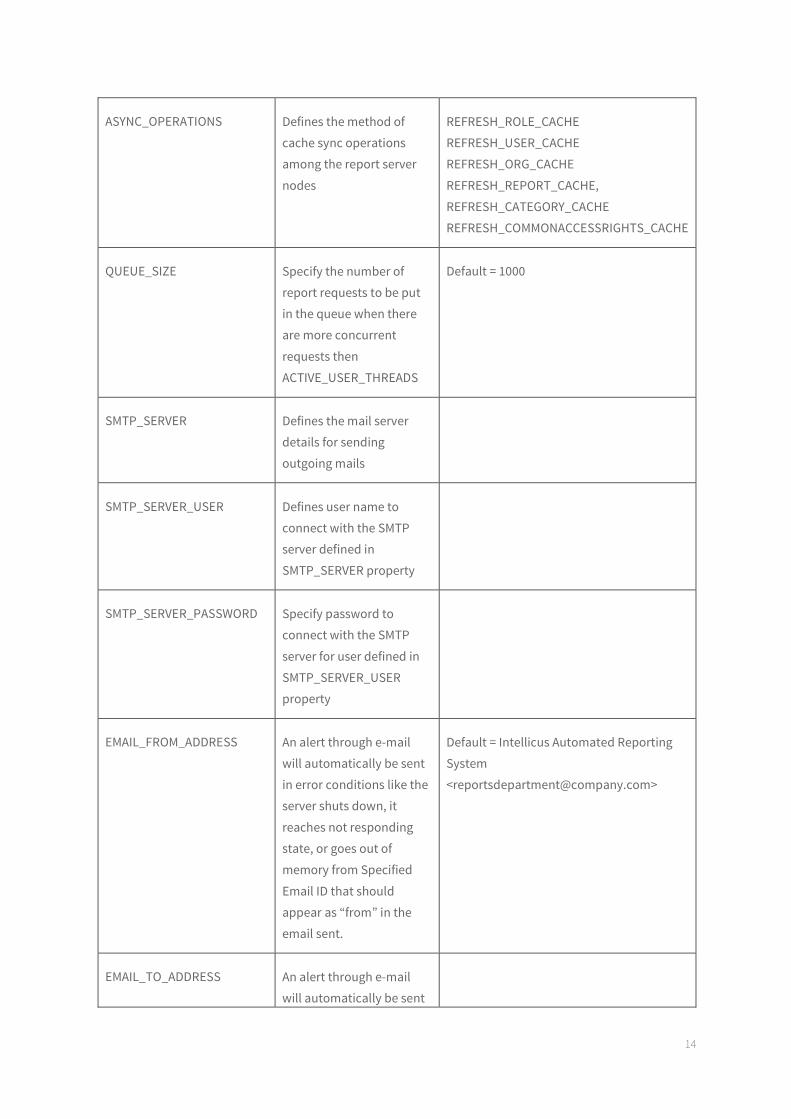
ASYNC_OPERATIONS Defines the method of
cache sync operations
among the report server
nodes
REFRESH_ROLE_CACHE
REFRESH_USER_CACHE
REFRESH_ORG_CACHE
REFRESH_REPORT_CACHE,
REFRESH_CATEGORY_CACHE
REFRESH_COMMONACCESSRIGHTS_CACHE
QUEUE_SIZE Specify the number of
report requests to be put
in the queue when there
are more concurrent
requests then
ACTIVE_USER_THREADS
Default = 1000
SMTP_SERVER Defines the mail server
details for sending
outgoing mails
SMTP_SERVER_USER Defines user name to
connect with the SMTP
server defined in
SMTP_SERVER property
SMTP_SERVER_PASSWORD Specify password to
connect with the SMTP
server for user defined in
SMTP_SERVER_USER
property
EMAIL_FROM_ADDRESS An alert through e-mail
will automatically be sent
in error conditions like the
server shuts down, it
reaches not responding
state, or goes out of
memory from Specified
Email ID that should
appear as “from” in the
email sent.
Default = Intellicus Automated Reporting
System
EMAIL_TO_ADDRESS An alert through e-mail
will automatically be sent
15
in error conditions like the
server shuts down, it
reaches not responding
state, or goes out of
memory to Specified Email
ID where the email should
be sent.
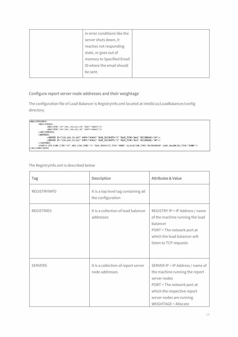
Configure report server node addresses and their weightage
The configuration file of Load Balancer is RegistryInfo.xml located at Intellicus/LoadBalancer/config
directory.
The RegistryInfo.xml is described below
Tag Description Attributes & Value
REGISTRYINFO It is a top level tag containing all
the configuration
REGISTRIES It is a collection of load balancer
addresses
REGISTRY IP = IP Address / name
of the machine running the load
balancer
PORT = The network port at
which the load balancer will
listen to TCP requests
SERVERS It is a collection of report server
node addresses
SERVER IP = IP Address / name of
the machine running the report
server nodes
PORT = The network port at
which the respective report
server nodes are running
WEIGHTAGE = Allocate
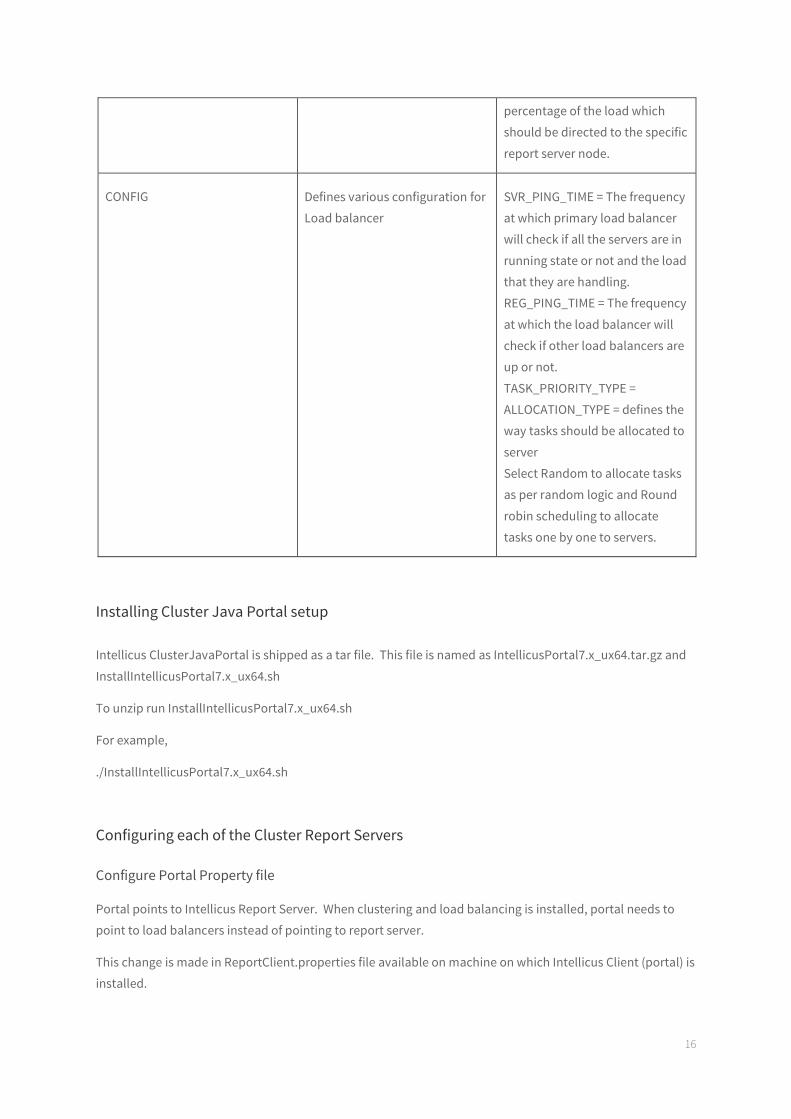
16
percentage of the load which
should be directed to the specific
report server node.
CONFIG Defines various configuration for
Load balancer
SVR_PING_TIME = The frequency
at which primary load balancer
will check if all the servers are in
running state or not and the load
that they are handling.
REG_PING_TIME = The frequency
at which the load balancer will
check if other load balancers are
up or not.
TASK_PRIORITY_TYPE =
ALLOCATION_TYPE = defines the
way tasks should be allocated to
server
Select Random to allocate tasks
as per random logic and Round
robin scheduling to allocate
tasks one by one to servers.
Installing Cluster Java Portal setup
Intellicus ClusterJavaPortal is shipped as a tar file. This file is named as IntellicusPortal7.x_ux64.tar.gz and
InstallIntellicusPortal7.x_ux64.sh
To unzip run InstallIntellicusPortal7.x_ux64.sh
For example,
./InstallIntellicusPortal7.x_ux64.sh
Configuring each of the Cluster Report Servers
Configure Portal Property file
Portal points to Intellicus Report Server. When clustering and load balancing is installed, portal needs to
point to load balancers instead of pointing to report server.
This change is made in ReportClient.properties file available on machine on which Intellicus Client (portal) is
installed.

17
When Intellicus is installed in Jakarta, this file is placed at path:
/intellicus/Jakarta/webapps/intellicus/client/config/ReportClient.properties
Change values of following properties:
REGISTRY_ENABLED
Set this property to TRUE. For example:
REGISTRY_ENABLED=TRUE
REGISTRIES
Specify all IP and port of all of the load balancers separated by only semi colon (no space).
For example:
REGISTRIES=201.90.56.23:60000;201.90.88.95:60002;
Save the file after making changes.
How property values are used
When value of REGISTRY_ENABLED is FALSE, it is assumed that clustering does not exist and client sends
request to the IP specified in REPORT_ENGINE_IP property.
When value of REGISTRY_ENABLED is set to TRUE, client sends request to the 1st load balancer IP specified
in REGISTRIES property.
If that load balancer is not available, client sends request to next load balancer in the list.
At a time multiple load balancers may be active. IP needs to be specified only by primary load balancer.
If the load balancer that client communicates with is not the primary load balancer, then it provides IP of
the primary load balancer to the client. (So that from next time all the client requests should go to primary
load balancer).
The client then checks if the load balancer IP provided exists in the list specified in REGISTRIES property.
Note: If the IP exists or it does not exist but list also has *, client sends the request to that load balancer. If it
does not exist in the list; and list does not have *, then the client falls back to the IP specified in
REPORT_ENGINE_IP property.
When client sends request to the primary load balancer, it provides IP of the server where the client should
send this request.
Now that the client know server IP, it sends the request to that server.
18
Running Sequence
There is no pre-defined running sequence for bringing up the components. Any of the components can be
started or stopped at any time.
To run a load balancer
Report Server is located in the /Intellicus/LoadBalancer/bin folder. To start the Load Balancer, run the file
runLB.sh.
./runLB.sh
Note: The load balancer that boots first, becomes primary load balancer. If primary load balancer fails, any
of the secondary load balancers will become primary load balancer.
To stop a load balancer
Run the file shutdownLB.sh. This file is available in Intellicus/LoadBalancer/bin folder.
./shutdownLB.sh
To run a cluster node
Intellicus Cluster Report Server is located in the /Intellicus/ClusterReportEngine/bin folder. To start the
Cluster Report Server, run the file run.sh.
./run.sh
To stop a cluster node
Run the file shutdown.sh. This file is located in the Intellicus/ClusterReportEngine/bin folder.
./shutdown.sh
19
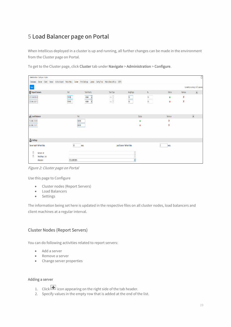
5 Load Balancer page on Portal
When Intellicus deployed in a cluster is up and running, all further changes can be made in the environment
from the Cluster page on Portal.
To get to the Cluster page, click Cluster tab under Navigate > Administration > Configure.
Figure 2: Cluster page on Portal
Use this page to Configure
Cluster nodes (Report Servers)
Load Balancers
Settings
The information being set here is updated in the respective files on all cluster nodes, load balancers and
client machines at a regular interval.
Cluster Nodes (Report Servers)
You can do following activities related to report servers:
Add a server
Remove a server
Change server properties
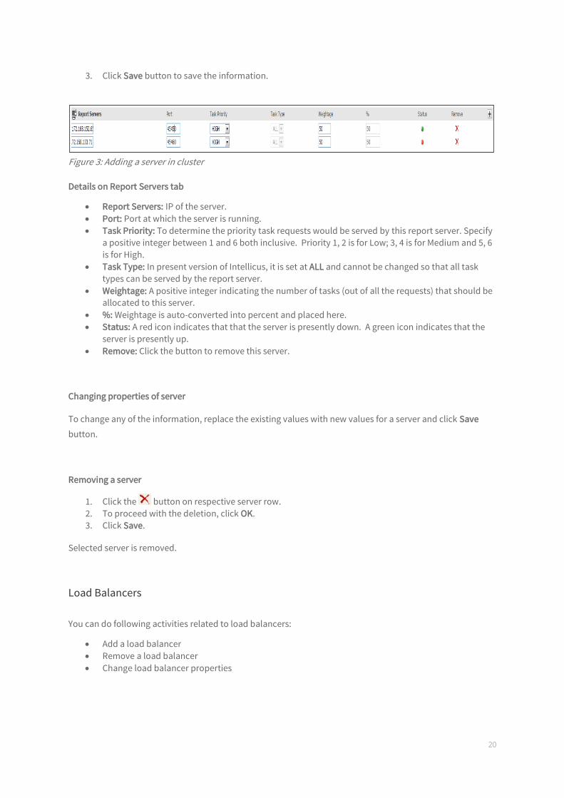
Adding a server
1. Click icon appearing on the right side of the tab header.
2. Specify values in the empty row that is added at the end of the list.
20
3. Click Save button to save the information.
Figure 3: Adding a server in cluster
Details on Report Servers tab
Report Servers: IP of the server.
Port: Port at which the server is running.
Task Priority: To determine the priority task requests would be served by this report server. Specify
a positive integer between 1 and 6 both inclusive. Priority 1, 2 is for Low; 3, 4 is for Medium and 5, 6
is for High.
Task Type: In present version of Intellicus, it is set at ALL and cannot be changed so that all task
types can be served by the report server.
Weightage: A positive integer indicating the number of tasks (out of all the requests) that should be
allocated to this server.
%: Weightage is auto-converted into percent and placed here.
Status: A red icon indicates that that the server is presently down. A green icon indicates that the
server is presently up.
Remove: Click the button to remove this server.
Changing properties of server
To change any of the information, replace the existing values with new values for a server and click Save
button.
Removing a server
1. Click the button on respective server row.
2. To proceed with the deletion, click OK.
3. Click Save.
Selected server is removed.
Load Balancers
You can do following activities related to load balancers:
Add a load balancer
Remove a load balancer
Change load balancer properties
21
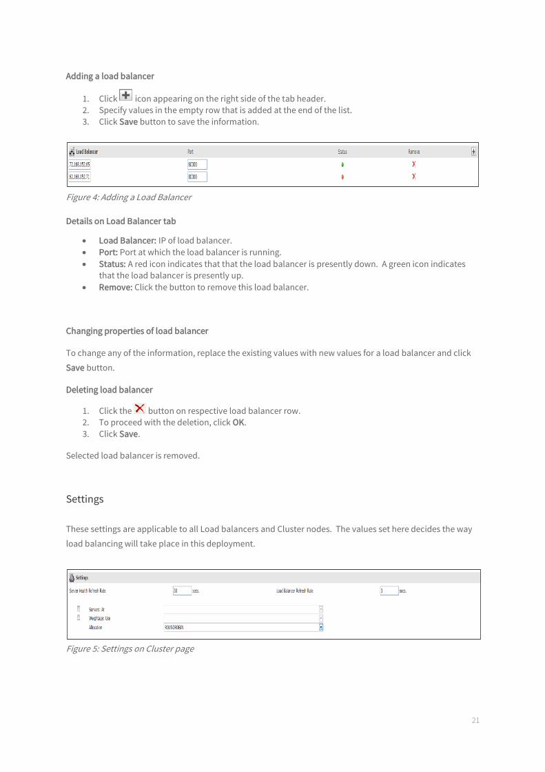
Adding a load balancer
1. Click icon appearing on the right side of the tab header.
2. Specify values in the empty row that is added at the end of the list.
3. Click Save button to save the information.
Figure 4: Adding a Load Balancer
Details on Load Balancer tab
Load Balancer: IP of load balancer.
Port: Port at which the load balancer is running.
Status: A red icon indicates that that the load balancer is presently down. A green icon indicates
that the load balancer is presently up.
Remove: Click the button to remove this load balancer.
Changing properties of load balancer
To change any of the information, replace the existing values with new values for a load balancer and click
Save button.
Deleting load balancer
1. Click the button on respective load balancer row.
2. To proceed with the deletion, click OK.
3. Click Save.
Selected load balancer is removed.
Settings
These settings are applicable to all Load balancers and Cluster nodes. The values set here decides the way
load balancing will take place in this deployment.
Figure 5: Settings on Cluster page

22
Details on Settings tab
Server Health Refresh Rate: The time interval after which primary load balancer will check if all the
servers are in running state or not and the load that they are handling.
Load Balancer Refresh Rate: The time interval after which load balancer will check if all the load
balancers are up or not.
Servers: At: Check this check box and select Exact Priority to allocate tasks set for respective server.
Select Upto Priority to allocate tasks set for the set category and higher.
Weightage: Use: Select this checkbox and select Specified Weight Only to allocate tasks as per set
weightage. Select Server Health Only to allocate tasks based on server health (actual load on
respective server).
Allocation: Select the way tasks should be allocated to servers. Select Random to allocate tasks as
per random logic. Select Round robin scheduling to allocate tasks one by one to servers.
After making changes click Save button to save the changes.