Embed Size (px)
DESCRIPTION
chattanooga
Citation preview

© 2007 Encore Medical, L.P.


Intelect® Transpor t Combo Therapy SystemTABLE OF CONTENTS
FOREWORD . .. .. .. .. .. .. .. .. .. .. .. .. .. .. .. .. .. .. .. .. .. .. .. 11- SAFETY PRECAUTIONS .. .. .. .. .. .. .. .. .. .. .. .. .. . 2-4
1.1 PRECAUTIONARY SYMBOL DEFINITIONS . 21.2 SAFETY PRECAUTIONS .. .. .. .. .. .. .. .. .. .. .. .. 2
2- THEORY OF OPERATION .. .. .. .. .. .. .. .. .. .. .. .. .. .. 52.1 OVERVIEW.. .. .. .. .. .. .. .. .. .. .. .. .. .. .. .. .. .. .. .. 52.2 POWER SUPPLY CIRCUIT .. .. .. .. .. .. .. .. .. .. .. 52.3 CONTROL BOARD .. .. .. .. .. .. .. .. .. .. .. .. .. .. .. 52.4 STIM BOARDS .. .. .. .. .. .. .. .. .. .. .. .. .. .. .. .. .. 52.5 ULTRASOUND BOARD
AND APPLICATOR .. .. .. .. .. .. .. .. .. .. .. .. .. .. ..52.6 USER INTERFACE AND ACCESSORIES.. .. .. 52.7 NIMH BATTERY (OPTIONAL) . .. .. .. .. .. .. .. .. 5
3- NOMENCLATURE . .. .. .. .. .. .. .. .. .. .. .. .. .. .. .. .. . 6-83.1 COMPONENT AND CONTROLS .. .. .. .. .. .. .. 63.2 HARDWARE AND SOFTWARE
SYMBOL DEFINITIONS .. .. .. .. .. .. .. .. .. .. .. .. 74- SPECIFICATIONS .. .. .. .. .. .. .. .. .. .. .. .. .. .. .. .. .. 9-13
4.1 INTELECT® TRANSPORT COMBO SYSTEM . 94.2 INTELECT® TRANSPORT ELECTROTHERAPY
WAVEFORM SPECIFICATIONS .. .. .. .. .. .. .. 104.3 INTELECT® TRANSPORT COMBO
ULTRASOUND SPECIFICATIONS . .. .. .. .. .. 135- TROUBLESHOOTING . .. .. .. .. .. .. .. .. .. .. .. .. .. 14-28 5.1 INTELECT® TRANSPORT COMBO ERROR MESSAGES . .. .. .. .. .. .. .. .. .. .. .. .. .. .. .. .. .. .. 14 5.2 INTELECT® TRANSPORT COMBO SYSTEM TESTING .. .. .. .. .. .. .. .. .. .. .. .. .. .. .. .. .. .. .. .. 16 5.3 ELECTRICAL SAFETY . .. .. .. .. .. .. .. .. .. .. .. .. 17 5.4 LEAKAGE TESTS . .. .. .. .. .. .. .. .. .. .. .. .. .. .. .. 17 5.5 VISUAL INSPECTION . .. .. .. .. .. .. .. .. .. .. .. .. 18 5.6 UNIT STARTUP AND FAN TESTING .. .. .. .. 18 5.7 ELECTRICAL STIMULATOR TEST SYSTEM SETUP .. .. .. .. .. .. .. .. .. .. .. .. .. .. .. .. 19 5.8 INTERFERENTIAL MODE TEST.. .. .. .. .. .. .. 20 5.9 PREMODULATED MODE TEST.. .. .. .. .. .. .. 20 5.10 RUSSIAN MODE TEST .. .. .. .. .. .. .. .. .. .. .. .. 21 5.11 HIGH VOLTAGE PULSED CURRENT (HVPC) MODE TEST .. .. .. .. .. .. .. .. .. .. .. .. .. 22 5.12 ULTRASOUND TESTS . .. .. .. .. .. .. .. .. .. .23 - 28 5.13 ULTRASOUND APPLICATOR IDENTIFICATION TEST . .. .. .. .. .. .. .. .. .. .. .. 23 5.14 ULTRASOUND APPLICATOR OUTPUT TEST.. .. .. .. .. .. .. .. .. .. .. .. .. .. .. .. .. 24 5.15 ULTRASOUND DUTY CYCLE TEST . .. .. .. .. 26 5.16 COMBO OPERATION TEST .. .. .. .. .. .. .. .. .. 286- REMOVAL & REPLACEMENT .. .. .. .. .. .. .. .. .. 29-40 6.1 SEPARATING TOP & BOTTOM .. .. .. .. .. .. .. .. 29 6.2 THERAPY SYSTEM FAN .. .. .. .. .. .. .. .. .. .. .. .. 30 6.3 POWER SUPPLY .. .. .. .. .. .. .. .. .. .. .. .. .. .. .. .. . 31 6.4 CHANNEL 1 STIM BOARD .. .. .. .. .. .. .. .. .. .. . 33 6.5 CHANNEL 2 STIM BOARD .. .. .. .. .. .. .. .. .. .. .. 34 6.6 ULTRASOUND BOARD- .. .. .. .. .. .. .. .. .. .. .. .. 35 6.7 CONTROL BOARD ASSEMBLY .. .. .. .. .. .. .. .. 36 6.8 LCD .. .. .. .. .. .. .. .. .. .. .. .. .. .. .. .. .. .. .. .. .. .. .. .. 38
6.9 KEYMAT, ON/OFF BUTTON AND UNIT TOP .. .. .. .. .. .. .. .. .. .. .. .. .. .. .. .. .. 39 6.10 PLYNTH . .. .. .. .. .. .. .. .. .. .. .. .. .. .. .. .. .. .. .. .. .. 407- GENERAL MAINTENANCE . .. .. .. .. .. .. .. .. .. .. .. 41 7.1 CLEANING THE SYSTEM .. .. .. .. .. .. .. .. .. .. 41 7.2 CALIBRATION REQUIREMENTS .. .. .. .. .. .. 41 7.3 FIELD SERVICE .. .. .. .. .. .. .. .. .. .. .. .. .. .. .. .. 41 7.4 FACTORY SERVICE .. .. .. .. .. .. .. .. .. .. .. .. .. .. 418- ULTRASOUND APPLICATOR CALIBRATION.. 42 8.1 GENERAL PROCEDURES .. .. .. .. .. .. .. .. .. .. 429- PARTS.. .. .. .. .. .. .. .. .. .. .. .. .. .. .. .. .. .. .. .. .. .. 43-4710- SCHEMATICS . .. .. .. .. .. .. .. .. .. .. .. .. .. .. .. .. .. 48-6611- WARRANTY . .. .. .. .. .. .. .. .. .. .. .. .. .. .. .. .. .. .. .. .. 67

1
Intelect® Transpor t Combo Therapy System
Read, understand, and follow the Safety Precautions and all other information contained in this manual.
This manual contains the necessary safety and field service information for those field service technicians, certified by Chattanooga Group, to perform field service on the Intelect® Transport Combo Therapy System.
At the time of publication, the information contained herein was current and up-to-date. However, due to continual technological improvements and increased clinical knowledge in the field of electrotherapy, as well as Chattanooga Group’s policy of continual improvement, Chattanooga Group reserves the right to make periodic changes and improvements to their equipment and documentation without any obligation on the part of Chattanooga Group. As significant changes occur to the Intelect® Transport Combo Therapy System, service bulletins may be made available on our web site (chattgroup.com) in lieu of reprinted manuals.
Technicians repairing the Intelect Transport Combo Therapy System agree to assume all risk and liability associated with this process.
This system is to be used only under the supervision of a licensed practitioner.
FOREWORD
©2007 Encore Medical, L.P. and its affiliates, Austin, Texas, USA. Any use of editorial, pictorial, or layout composition of this publication without express written
consent from Chattanooga Group of Encore Medical, L.P. is strictly prohibited. This publication was written, illustrated, and prepared for print by Chattanooga
Group of Encore Medical, L.P.

2
Intelect® Transpor t Combo Therapy System
1.1 PRECAUTIONARY SYMBOL DEFINITIONSThe precautionary instructions found in this manual are indicated by specific symbols. Understand these symbols and their definitions before operating or servicing this equipment. The definitions of these symbols are as follows:
A. CAUTION Text with a “CAUTION” indicator will explain possible safety infractions that have the potential to cause minor to moderate injury or damage to equipment.
B. WARNING Text with a “WARNING” indicator will explain possible safety infractions that will potentially cause serious injury and equipment damage.
C. DANGER Text with a “DANGER” indicator will explain possible safety infractions that are imminently hazardous situations that would result in death or serious injury.
D. DANGEROUS VOLTAGE Text with a “Dangerous Voltage” indicator serves to inform the user of possible hazards resulting in the electrical charge delivered to the patient in certain treatment configurations of TENS waveforms.
E. CORROSIVE HAZARD (NIMH BATTERY)Text with a “Corrosive Hazard” indicator will explain possible safety infractions if the chemical components of this product are exposed to air, skin, or other materials.
F. NOTE: Throughout this manual “NOTE” may be found. These Notes are helpful information to aid in the particular area or function being described.
1.2 SAFETY PRECAUTIONSRead, understand, and follow all safety precautions found in this manual. Below are general safety precautions that must be read and understood before attempting any service techniques on these systems.
Read, understand, and practice the precautionary and operating instructions. Know the limitations and hazards associated with using any electrical stimulation or ultrasound device. Observe the precautionary and operational decals placed on the unit.
DO NOT operate the Intelect Transport Combo unit when connected to any unit other than Chattanooga Group devices.
DO NOT operate this unit in an environment where other devices are being used that intentionally radiate electromagnetic energy in an unshielded manner. Portable and mobile RF communications equipment can affect Medical Electrical Equipment.
DO NOT use sharp objects such as a pencil point or ballpoint pen to operate the buttons on the control panel.
This unit should be operated, transported, and stored in temperatures between 15° C and 40° C (59° F and 104° F), with relative humidity ranging from 30%-60%, and where the atmospheric pressure is between 950 h Pa and 1050 h Pa.
The Intelect battery pack is designed for use only with Chattanooga Group Intelect Transport, Stim, Combo, and Ultrasound systems.
Before use, remove the yellow, plastic cap from the sound head.
The unit should be routinely checked before each use to determine that all controls function normally; especially that the intensity control properly adjusts the intensity of the electrotherapy and ultrasonic power output in a stable manner. Also, determine that the treatment time control actually terminates electrotherapy and ultrasonic power output when the timer reaches zero.
Inspect cables and connectors before each use.
The Intelect Transport Combo is not designed to prevent the ingress of water or liquids. Ingress of water or liquids could cause malfunction of internal components of the system and therefore create a risk of injury to the patient.
DO NOT permit any foreign materials or liquids to enter the unit. Take care to prevent any foreign materials including, but not limited to, inflammables, water, and metallic objects from entering the unit. These may cause unit damage, malfunction, electrical shock, fire, or personal injury.
Handle the applicator with care. Inappropriate handling of the applicator may adversely affect its characteristics.
Before each use, inspect the applicator for cracks, which may allow the ingress of conductive fluid.
This equipment generates, uses, and can radiate radio frequency energy and, if not installed and used in accordance with the instructions, may cause harmful interference to other devices in the vicinity. However, there is no guarantee that interference will not occur in a particular installation. Harmful interference to other devices can be determined by turning this equipment on and off. Try to correct the interference using one or more of the following: reorient or relocate the receiving device, increase the separation between the equipment, connect the equipment to an outlet on a different circuit from that to which the other device(s) are connected and consult
the factory field service technician for help.
•
•
•
•
•
•
••
••
•
•
•
•
1- SAFETY PRECAUTIONS

3
Intelect® Transpor t Combo Therapy System1- SAFETY PRECAUTIONS
These devices are restricted to sale by, or on the order of, a physician or licensed practitioner. This device should be used only under the continued supervision of a physician or licensed practitioner.
For continued protection against fire hazard, replace fuses only with ones of the same type and rating.
Make certain the unit is electrically grounded by connecting only to a grounded electrical service receptacle conforming to the applicable national and local electrical codes.
The Intelect Mobile Ultrasound should not be used adjacent to or stacked with other equipment, and if adjacent or stacked use is necessary, the Intelect Mobile Ultrasound should be observed to verify normal operation in the configuration in which it will be used.
The user must keep the device out of the reach of children.
Powered muscle stimulators should be used only with the leads and electrodes recommended for use by the manufacturer.
Before administering any treatment to a patient you should become acquainted with the operating procedures for each mode of treatment available, as well as the indications, contraindications, warnings, and precautions. Consult other resources for additional information regarding the application of electrotherapy and ultrasound.
To prevent electrical shock, disconnect the unit from the power source before attempting any maintenance procedures.
Keep electrodes separated during treatment. Electrodes in contact with each other could result in improper stimulation or skin burns.
•
•
•
•
••
•
•
•
Long term effects of chronic electrical stimulation are unknown.
Stimulation should not be applied over the anterior neck or mouth. Severe spasm of the laryngeal and pharyngeal muscles may occur and the contractions may be strong enough to close the airway or cause difficulty in breathing.
Stimulation should not be applied transthoracically because the introduction of electrical current into the heart may cause cardiac arrhythmia.
Stimulation should not be applied over swollen, infected, and inflamed areas or skin eruptions, e.g., phlebitis, thrombophlebitis, varicose veins, etc.
Stimulation should not be applied over, or in proximity to, cancerous lesions.
Output current density is inversely related to electrode size. Improper application may result in patient injury.
Always keep the sound head in constant motion.
Always keep the sound head in full contact with the patient’s skin or submerged under water when setting intensity.
Use ample conductive gel to ensure good coupling throughout the treatment. If needed, apply when setting intensity.
Be sure to read all instructions for operation before treating a patient.
Dispose of all products in accordance with local and national regulations and codes.
Use of controls, adjustments, or performance of procedures other than those specified herein may result in hazardous exposure to ultrasonic energy.
Use of controls or adjustments or performance of procedures other than those specified herein may result in hazardous conditions causing damage to the battery pack or cells.
To prevent electrical shock, disconnect the battery pack from the system before attempting any maintenance procedures.
Do not drop the applicator on hard surfaces. Do not cool an overheated sound head with ice water or ice packs. Do not allow the sound head to reach maximum temperatures repeatedly. All of these conditions are likely to damage the sound head crystal. Damage resulting from these conditions is not covered under the warranty.
In the event that an Error message or Warning appears beginning with a 2 or 3, immediately stop all use of the unit and contact the dealer or Chattanooga Group for service. Errors and Warnings in these categories indicate an internal problem with the unit that must be tested by Chattanooga Group or a Field Service Technician certified by Chattanooga Group before any further operation or use of the system.
•
•
•
•
•
•
••
•
•
•
•
•
•
•
•
1.2 SAFETY PRECAUTIONS (CONTINUED)
Where the integrity of the external protective earth conductor arrangement is in doubt, equipment shall be operated from its internal electrical power source.
Using a high intensity electrotherapy setting in conjunction with high intensity ultrasound setting may cause the unit to reset.
The battery pack should be removed when storing the unit for extended periods of time.
DO NOT disassemble, modify, or remodel the unit or accessories. This may cause unit damage, malfunction, electrical shock, fire, or personal injury.
DO NOT remove the cover. This may cause unit damage, malfunction, electrical shock, fire, or personal injury. There are no user-serviceable parts inside the unit. If a malfunction occurs, discontinue use immediately and consult the dealer for repair service.
Failure to use and maintain the Intelect Transport Combo and its accessories in accordance with the instructions outlined in this manual will invalidate your warranty.
The Nylatex® Wraps contain dry natural rubber and may cause allergic reactions in patients with allergies to latex.
•
•
•
•
•
•
•

4
Intelect® Transpor t Combo Therapy System1- SAFETY PRECAUTIONS
NiMH Batteries contain Class E corrosive materials. In the event of battery cell rupture or leakage, handle battery pack wearing neoprene or natural rubber gloves. Contents of a ruptured or leaking battery can cause respiratory irritation. Hypersensitivity to nickel can cause allergic pulmonary asthma. Contents of cell coming in contact with skin can cause skin irritation and/or chemical burns.
Never, under any circumstances, open the battery pack housing or cells. Should an individual battery from a battery pack become disassembled, spontaneous combustion of the negative electrode is possible. There can be a delay between exposure to air and spontaneous combustion.
Charge the battery pack according to the instructions found in this manual. Never attempt to charge the battery pack on any other charging mechanism.
Use the battery pack only with the Intelect Transportable units.
Do not reverse the polarity of the battery pack. Doing so can increase the individual cell temperature and cause cell rupture or leakage.
Never dispose of the battery pack in fire. Never short circuit the battery pack. The battery pack may explode, ignite, leak, or get hot causing serious personal injury.
Dispose of NiMH batteries according to national, state, and local codes and regulations.
•
•
•
•
•
•
•
1.2 SAFETY PRECAUTIONS (CONTINUED)
Use of a unit that indicates an Error or Warning in these categories may pose a risk of injury to the patient, user, or extensive internal damage to the system.
Do not turn the unit on or off while it is connected to the patient.
Do not apply the Ultrasound Applicator to the patient during the Head Warming period. Applicator must remain in Applicator Hook during the Head Warming period.
Use only accessories that are specially designed for this (table, unit, device, etc). Do not use accessories manufactured by other companies on this (table, unit, device, etc). Chattanooga Group is not responsible for any consequence resulting from using products manufactured by other companies. The use of other accessories or cables may result in increased emissions or decreased immunity of this (table, unit, device, etc).
•
•
•
•
Stimulus delivered by the waveforms of this device, in certain configurations, will deliver a charge of 25 microcoulombs (μC) or greater per pulse and may be sufficient to cause electrocution. Electrical current of this magnitude must not flow through the thorax because it may cause a cardiac arrhythmia.
Patients with an implanted neurostimulation device must not be treated with or be in close proximity to any shortwave diathermy, microwave diathermy, therapeutic ultrasound diathermy, or laser diathermy anywhere on their body. Energy from diathermy (shortwave, microwave, ultrasound, and laser) can be transferred through the implanted neurostimulation system, can cause tissue damage, and can result in severe injury or death. Injury, damage, or death can occur during diathermy therapy even if the implanted neurostimulation system is turned “off.”
DO NOT connect the unit to an electrical supply without first verifying that the power supply is the correct voltage.
Incorrect voltage may cause unit damage, malfunction, electrical shock, fire, or personal injury. Your unit was constructed to operate only on the electrical voltage specified on the Voltage Rating and Serial Number Plate. Contact your Chattanooga Group dealer if the unit is not properly rated.
•
•
•
•

5
Intelect® Transpor t Combo Therapy System
2.1 OVERVIEW The Intelect Transport Combo Therapy System is comprised of several PC board assemblies housed within a common enclosure. These assemblies each support a distinct function in the product. The basic elements are User Interface, Control Board, Stim Boards, Ultrasound Board, Ultrasound Applicator, and Power Supply Circuits.
2.2 POWER SUPPLY CIRCUIT A universal 75 Watt input power supply provides the system with the required 24 volts DC. The supply is connected to the mains at all times when the Mains Power Cord is attached and plugged into an outlet supplying 100 - 240 VAC. The 24 V supply is regulated locally at each PC board as required.
2.3 CONTROL BOARD The Control Board serves just as its name implies. It controls the operation of the Stim Boards, Ultrasound Board, User Interface, and Accessories. The Control Board communicates to the Stim Boards and Ultrasound Board through a proprietary bus. The Control Board drives the display. The Control Board reads the menu buttons. The Control Board also reads the amplitude and the Contrast Control on the systems. Sound output is generated by the Control Board and routed to an internal speaker.
2.4 STIM BOARDS The Stim Boards create all muscle stimulation output. Communication to the Stim Boards is via a proprietary bus. A Processor on each Stim Board acts on messages passed to it by the Control Board to set up waveforms and adjust output amplitude. Information can likewise be passed from each Stim Board back to the Control Board for monitoring current, etc. If a Stim Board does not respond as expected to a command from the Control Board, output is stopped and an Error Message is generated.
2.5 ULTRASOUND BOARD AND APPLICATOR The Ultrasound Board generates the 1 or 3.3 MHz output to drive the Sound Head of the Applicator. The Ultrasound Board is accessed through the proprietary bus by the Control Board. It can provide current and voltage information about the ultrasound output of the board. The calibration data for the Sound Head is passed through the Ultrasound Board from the Applicator to the Control Board. By storing the calibration data in the Applicator, there is no calibration necessary for the Ultrasound Board and any calibrated Chattanooga Group Intelect Transport Ultrasound Applicator can be connected and operated to provide accurate output.
2.6 USER INTERFACE AND ACCESSORIES The LCD display panel provides the operator visible feedback in the way of menu choices. Pressing the User Interface buttons makes selections from the menus. The Control Board interprets these user inputs and responds accordingly. Audible feedback is given for such events as key presses and end of treatment.
2.7 NIMH BATTERY (OPTIONAL) The NiMH Battery Module incorporates a Nickel Metal Hydride (NiMH) Battery Pack and a PC Board. The PC Board monitors the Battery Charge Level. The Battery Pack supplies the required 24 VDC to the system which is then distributed to the respective PCB’s through the Universal Power Supply. The Battery Pack is interfaced with the system via a Wire Harness that facilitates communication with the Control Board and delivery of power to the Combination Therapy System. When the Therapy System is connected to a Mains Power Supply via the Mains Power Cord, the NiMH Battery Pack will charge. Once the Battery Pack is fully charged, the software will stop the charging process, eliminating the possibility of overcharging. Battery power is used only when the Therapy System is not connected to a Mains Power Supply.
2- THEORY OF OPERATION

6
Intelect® Transpor t Combo Therapy System
The nomenclature graphics below, Figure 3.1, indicate the general locations of the exterior components of the Intelect Transport Combo System.
Know the components and their functions before performing any operation of or service to the Intelect Transport Combo System.
FIGURE 3.1
3- NOMENCLATURE3.1 COMPONENTS AND CONTROLS
Power
On⁄Off
LCD
TIME
Clinical
Library
Back
STOP
Down
Arrow PAUSE
Accessory
Panel
Parameter
Display ⁄ Enter
START
INTENSITY
Up
Arrow
LCD Intensity⁄
Contrast Dial
Channel 1
Lead Wire
Connection
Channel 2
Lead Wire
Connection
Sound Head
LED Indicator
(Output Power)
Applicator
Ultrasound
Applicator
Connection
Power Cord
Connection
Battery
Compartment
Serial
Decal

7
Intelect® Transpor t Combo Therapy System
The symbols below are found on the system as well as within the software. These symbols are defined for the purpose of recognition and functionality when operating or performing service on the Intelect Transport Combo System.
Know the symbols and their definitions before performing any operation of or service to the Intelect Transport Combo System.
Intelect Transport Combo System Hardware Symbols
3- NOMENCLATURE
3.2 HARDWARE AND SOFTWARE SYMBOL DEFINITIONS
Power On/Off The Power On/Off button controls the flow of electricity to the unit.
NOTE: Make certain there are no electrodes on the patient when turning the unit on or off.
LCD The LCD (Liquid Crystal Display) allows the user to view and monitor the information displayed before, during, and after therapy.
Clinical Library Select this button to access the following functions:
Retrieve User Protocol
Restore Factory Settings
Restore Factory Protocols
Languages
View Unit Information
TIME Press the Up or Down arrow buttons to set total treatment time of therapy.
Back Use this button to return to the previous window.
STOP Select this button to stop a treatment session.
Down Arrow When the window displays a list of options, press the Down Arrow button to scroll down the list.
PAUSE Use this button to pause the treatment session. To restart therapy, press the PAUSE button.
Sound Head The aluminum face of the applicator that contacts the patient’s skin. It covers a transducer mechanism that converts electrical energy to mechanical energy in the form of a vibrating crystal.
LED Indicator (Output Power) When illuminated, this green light signifies that ultrasound energy is being distributed through the applicator.
Applicator The hand held assembly used to deliver ultrasonic energy. The applicator includes the sound head, transducer, and related electronics.
Accessory Panel The Accessory Panel serves as a port of connection for the electrodes and ultrasound applicator.
Channel 1 Lead Wire Connection This port serves as the connection point between the unit and the Channel 1 Lead Wire.
Channel 2 Lead Wire Connection This port serves as the connection point between the unit and the Channel 2 Lead Wire.
•••••

8
Intelect® Transpor t Combo Therapy System
Ultrasound Applicator Connection This port serves as the connection point between the unit and the ultrasound applicator.
START Select Start to begin a treatment session.
Parameter Display/Enter Select this button to display the parameters of the waveform during treatment. Also, this button is used to accept the highlighted selection.
INTENSITY Use the up or down arrow on the INTENSITY button to increase or decrease output power.
Up Arrow When the window displays a list of options, press the Up Arrow button to scroll up the list.
Battery Indicator When displayed on the LCD, this symbol indicates the battery pack option is present on the unit. This symbol also displays the charge status of the battery.
LCD Intensity/Contrast Dial If the intensity of the LCD display diminishes, turn the dial until the display contrast is optimal.
Charge Indicator This symbol displays when the unit is connected to mains power and the battery pack is charging.
NOTE: During battery operation, if the unit is left on, but is not active for more than five minutes, it will power off to conserve battery power. To restore power, press the Power On/Off button.
3.2 HARDWARE AND SOFTWARE SYMBOL DEFINITIONS (CONTINUED)
3- NOMENCLATURE

9
Intelect® Transpor t Combo Therapy System
Figure 4.1 below provides physical details of the Intelect Transport Combo. This section also provides waveform specifications to aid in troubleshooting.
Refer to this section when performing troubleshooting, replacement, and repair of the Intelect Transport Combo System.
A. Intelect Transport Combination Therapy System Physical Specifications
DimensionsWidth .. .. .. .. .. .. .. .. .. .. .. .. .. .. .. .. .. .. .. .. .. .. .. .. .. .. .. .. .. 10.125 in (25.7 cm)Height . .. .. .. .. .. .. .. .. .. .. .. .. .. .. .. .. .. .. .. .. .. .. .. .. .. .. .. .. 7.250 in (18.4 cm)
Depth .. .. .. .. .. .. .. .. .. .. .. .. .. .. .. .. .. .. .. .. .. .. .. .. .. .. .. .. .. .. 11.5 in (29.2 cm)
WeightStandard Weight (with base) .. .. .. .. .. .. .. .. .. .. .. .. .. .. .. .. .. .. .5.07 lb (2.3 kg)
Battery Pack . .. .. .. .. .. .. .. .. .. .. .. .. .. .. .. .. .. .. .. .. .. .. .. .. .. .. ..1.87 lb (0.85 kg)
PowerInput. .. .. .. .. .. .. .. .. .. .. .. .. .. .. .. .. .. .. .. .. .. ..100 - 240 VAC, 50/60 Hz 100 VA
Output . .. .. .. .. .. .. .. .. .. .. .. .. .. .. .. .. .. .. .. .. .. .. .. .. .. .. .. .. .. .. +24 V, 3.125 A
Fuses .. .. .. .. .. .. .. .. .. .. .. .. .. .. .. .. .. .. 3.15 A Time Lag (not user serviceable)
Electrical Class .. .. .. .. .. .. .. .. .. .. .. .. .. .. .. .. .. .. .. .. .. .. .. .. .. .. .. .. .. .. .. CLASS I
Electrical TypeUltrasound TYPE B .. .. .. .. .. .. .. .. .. .. .. .. .. .. .. .. .. .. .. .. .. .. .. .. .. .. .. .. .. .. .
Electrotherapy TYPE BF . .. .. .. .. .. .. .. .. .. .. .. .. .. .. .. .. .. .. .. .. .. .. .. .. .. .. .. .
Battery Type . .. .. .. .. .. .. .. .. .. .. .. .. .. .. .. .. .. .. .. .. .Nickel Metal Hydride (NiMH)(1.2 V x 20 size AA)
Operating EnvironmentTemperature .. .. .. .. .. .. .. .. .. .. .. .. .. .. .. .. .. .. .. .. .. ..Between 59° F and 104° F
(15° C and 40° C)Relative Humidity .. .. .. .. .. .. .. .. .. .. .. .. .. .. .. .. .. .. .. .. .. .. .. .. .. .. .. 30%-60%Atmospheric Pressure .. .. .. .. .. .. .. .. .. .. .. .. .. .. .. .. .. .. .. .. .. .. . 950-1,050 h Pa
Complies with:UL/IEC/EN 60601-1IEC/EN 60601-1-2IEC 60601-2-10IEC 60601-2-5
FIGURE 4.1
4- SPECIFICATIONS4.1 INTELECT TRANSPORT COMBO SYSTEM
WIDTHWIDTH
HEIGHTHEIGHT
DEPTHDEPTH

10
Intelect® Transpor t Combo Therapy System
A. High Voltage Pulsed Current (HVPC)- Figure 4.2 (Factory Default Setting)
The High Voltage Pulsed Current (HVPC) has a very brief pulse duration characterized by 2 distinct peaks delivered at high voltage. The waveform is monophasic (current flows in one direction only). The high voltage causes a decreased skin resistance, making the current comfortable and easy to tolerate.
Output Mode . . . . . . . . . . . . . . . . . . . . . . . Electrodes
Amplitude . . . . . . . . . . . . . . . . . . . . . . . . . . . . 0-500 V*
Polarity . . . . . . . Positive or Negative (Negative)
Ramp . . . . . . . . .0.5 sec, 1 sec, 2 sec, 5 sec (2 sec)
Display . . . . . . . . . . . Peak Current or Volts (Volts)
Sweep . . . . . . . . . . . . . . . . . . . . . . . . .Off, 80/120 pps, 1/120 pps, 1/10 pps (Off)
Frequency . . . . . . . . . . . . . . 10-120 pps (100 pps)
Cycle Time . . . . . . 5/5, 4/12, 10/10, 10/20, 10/30, 10/50, and Continuous (Continuous)
Constant Mode . . . . . . . . . . . . . . . . . . CV (only)** (CV)
Treatment Time . . . . . . . . .1-60 Minutes (20 min)
The specifications found in this section provide the necessary waveform specifications to aid in troubleshooting. A waveform graphic from an oscilloscope is also provided for clarification.
Refer to this section when performing troubleshooting, replacement, and repair of the Intelect Transport Combo System.
FIGURE 4.2
4.2 INTELECT TRANSPORT ELECTROTHERAPY WAVEFORM SPECIFICATIONS
4- SPECIFICATIONS
* ESTI-2 Load Box
** CV = Constant Voltage

11
Intelect® Transpor t Combo Therapy System
FIGURE 4.3
* ESTI-2 Load Box
**CC= Constant Current
CV= Constant Voltage
4- SPECIFICATIONS4.2 INTELECT TRANSPORT ELECTROTHERAPY WAVEFORM SPECIFICATIONS (CONTINUED)
B. Premodulated - Figure 4.3 (Factory Default Setting)
Premodulated Current is a medium frequency waveform. Current is distributed from one channel (two electrodes). The current intensity is modulated: it increases and decreases at a regular frequency ( the Amplitude Modulation Frequency).
Output Mode . . . . . . . . . . . . . . . . . . . . . . . Electrodes
Amplitude . . . . . . . . . . . . . . . . . . . . . . . . . .0-100 mA*
Carrier Frequency . . . . . . . . . . 2500 Hz (2500 Hz)
Ramp . . . . . . . . . . . . . . . . . . . . . . . . . . . . . 2 sec (2 sec)
Display . . . . . . . . . . . Peak Current or Volts (Volts)
Sweep . . . . . . . . . . . . . . . . . . . . . . On, 1-200 Hz (On)
Cycle Time . . . . . . 5/5, 4/12, 10/10, 10/20, 10/30, 10/50, and Continuous (Continuous)
Beat Low Frequency . . . . . . . . . . . . . . . . . 1- 199 Hz
Beat High Frequency . . . . . . . . . . . . . . . . .2-200 Hz
Constant Mode . . . . . . . . . . . . . . . . . . CC or CV** (CC)
Treatment Time . . . . . . . . .1-60 Minutes (20 min)
12
Intelect® Transpor t Combo Therapy System
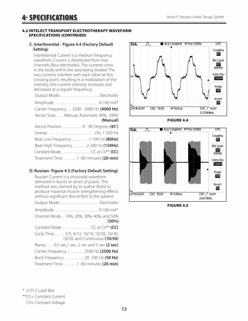
C. Interferential - Figure 4.4 (Factory Default Setting)
Interferential Current is a medium frequency waveform. Current is distributed from two channels (four electrodes). The currents cross in the body within the area being treated. The two currents interfere with each other at this crossing point, resulting in a modulation of the intensity (the current intensity increases and decreases at a regular frequency).
Output Mode . . . . . . . . . . . . . . . . . . . . . . . Electrodes
Amplitude . . . . . . . . . . . . . . . . . . . . . . . . . .0-100 mA*
Carrier Frequency . . . 2500 - 5000 Hz (4000 Hz)
Vector Scan . . . . .Manual, Automatic 40%, 100% (Manual)
Vector Position . . . . . . . . . . . 0 - 90 Degrees (45˚)
Sweep . . . . . . . . . . . . . . . . . . . . . . . . . . . .On, 1-200 Hz
Beat Low Frequency . . . . . . . . . . 1-199 Hz (80Hz)
Beat High Frequency . . . . . . . .2-200 Hz (150Hz)
Constant Mode . . . . . . . . . . . . . . . . . . . CC or CV** (CC)
Treatment Time . . . . . . . . 1 -60 minutes (20 min)
D. Russian- Figure 4.5 (Factory Default Setting)
Russian Current is a sinusoidal waveform delivered in bursts or series of pulses. This method was claimed by its author (Kots) to produce maximal muscle strengthening effects without significant discomfort to the patient.
Output Mode . . . . . . . . . . . . . . . . . . . . . . . Electrodes
Amplitude . . . . . . . . . . . . . . . . . . . . . . . . . .0-100 mA*
Channel Mode . . 10%, 20%, 30%, 40%, and 50% (50%)
Constant Mode . . . . . . . . . . . . . . . . . CC or CV** (CC)
Cycle Time . . . . . . 5/5, 4/12, 10/10, 10/20, 10/30, 10/50, and Continuous (10/50)
Ramp . . . . . 0.5 sec,1 sec, 2 sec and 5 sec (2 sec)
Carrier Frequency . . . . . . . . . . 2500 Hz (2500 Hz)
Burst Frequency . . . . . . . . . . . 20 -100 Hz (50 Hz)
Treatment Time . . . . . . . . 1 -60 minutes (20 min)
FIGURE 4.4
FIGURE 4.5
4- SPECIFICATIONS
4.2 INTELECT TRANSPORT ELECTROTHERAPY WAVEFORM SPECIFICATIONS (CONTINUED)
* ESTI-2 Load Box
**CC= Constant Current
CV= Constant Voltage

13
Intelect® Transpor t Combo Therapy System
A. Ultrasound
Frequency . . . . . . . . . . 1 MHz, ± 5%; 3.3 MHz, ±5%
Duty Cycles . . . . 10%, 20%, 50%, and Continuous
Pulse Frequency . . . . . . . . . . . . . . . . . . . . . . . . . 100 Hz
Pulse Duration . . . . 1 mSec, ±20%; 2 mSec, ±20% 5 mSec, ±20%
Output Power
10 cm2 Crystal . . . . . . . . . . . . . 0-20 Watts at 1 MHz, 0-10 Watts at 3.3 MHz
5 cm2 Crystal . . . . . . . . 0-10 Watts, 1 and 3.3 MHz
2 cm2 Crystal . . . . . . . . . .0-4 Watts, 1 and 3.3 MHz
1 cm2 Crystal . . . . . . . . . . . 0-2 Watts 3.3 MHz Only
Amplitude . . 0 - 2.5 w/cm2 in Continuous mode, 0-3 w/cm2 in Duty Cycle modes
Output accuracy . . . . . . . . . . .± 20% above 10% of maximum
Temporal Peak to Average Ratios:
2:1, ± 20%, at 50% Duty Cycle
5:1, ± 20%, at 20% Duty Cycle
9:1, ± 20%, at 10% Duty Cycle
Beam Non uniformity Ratio . . . . . . . . . . . . . . 5.0 : 1 maximum
Beam Type . . . . . . . . . . . . . . . . . . . . . . . . . . Collimating
Effective Radiating Areas
10 cm2 Crystal - 6.8 cm2 - 10.0 cm2
5 cm2 Crystal - 3.5 cm2 - 5.0 cm2
2 cm2 Crystal - 1.4 cm2 - 2.0 cm2
1 cm2 Crystal - 0.7 cm2 - 1.0 cm2
Treatment Time . . . . . . . . . . . . . . . . . . . .1-30 Minutes
Do not apply the Ultrasound Applicator to the patient during the Head Warming period. Applicator must remain in Applicator Hook during the Head Warming period.
4.3 INTELECT® TRANSPORT COMBO THERAPY SYSTEM ULTRASOUND SPECIFICATIONS
4- SPECIFICATIONS
This section provides the necessary Ultrasound Specifications to aid in troubleshooting. Refer to these specifications as necessary when troubleshooting the Ultrasound PC Board and Applicators.
B. Head Warming Feature SpecificationsThe Head Warming feature of an Intelect Transport Combo Therapy System utilizes Ultrasound output resulting in warming of the Sound Head to increase patient comfort.
With Head Warming enabled, ultrasound is emitted without pressing the START button. The Applicator LED will not illuminate during the Head Warming period. US Channel will indicate "Warming".
Output . . 0 - 50% Cycling of maximum power
Frequency . . . . . . . . . . . . . . . . . . . . . . . . . . . . 3.3 MHz
Sound Head Temperature . . . . . . 85 °F - 110 °F (29.4 °C - 43.3 °C)

14
Intelect® Transpor t Combo Therapy System
A. The following information is provided as an aid in defining the Software Error Messages of the Intelect Transport Therapy System. Once a particular Error Message is defined, the information will also list probable causes and possible remedies. Once the problem area is determined, subsequent tests for verification will be necessary to determine a “Bad Board”.
All Troubleshooting and tests will be to validate a “Bad Board” only. No component level troubleshooting information is or will be provided by Chattanooga Group for field troubleshooting of board components.
B. Once a particular PC Board has been determined as bad, refer to the appropriate Removal and Replacement Section for the board affected and follow the instructions for replacement of the board.
5.1 INTELECT TRANSPORT COMBO THERAPY SYSTEM ERROR MESSAGES
5- TROUBLESHOOTING
ERRORCODE
ERRORTYPE
DEFINITION PROBABLE CAUSES POSSIBLE REMEDY
USER CORRECTABLE WARNING MESSAGES
100101
WARNINGWARNING
Ultrasound Applicator became unpluggedUltrasound Applicator unplugged
Ultrasound Applicator was unplugged while an Ultrasound treatment was runningUser attempted to start an Ultrasound treatment, but no Ultrasound Applicator was plugged into unit
Plug Ultrasound Applicator into proper receptacle on unit making certain it is completely seated
102 WARNING Ultrasound Applicator not calibrated The Ultrasound Applicator plugged into the unit needs to be calibrated
Contact dealer or Chattanooga Group for service.
103104105
WARNINGWARNINGWARNING
Ultrasound Channel not availableStim Channel not availableStim Channel not available
User attempted to select Combo treatment, but the Ultrasound Channel was already in useUser attempted to select Combo treatment, but the Ultrasound Channel was already in useUser attempted to select a two channel Electrotherapy treatment, but at least one of the two stim channels were already in use
Wait until Ultrasound treatment is completed or stop Ultrasound treatment and try again
106 WARNING Over current Stim channel has exceeded allowed current level and the treatment has been stopped
Reset treatement parameters and attempt session again
107 WARNING Bad Contact Quality Electrode contact is poor Apply new electrodes to the treatment area
108 WARNING Shorted Lead Wires Lead Wires are bad Replace with new lead wires
109 WARNING Power Supply current limit User attempted to start two channels of Electrotherapy while running an Ultrasound treatment with a 10 cm2
Ultrasound Applicator and Ultrasound Output is currently set to greater than 15 Watts.
Wait until Ultrasound treatment is completed or stop Ultrasound treatment and try again or decrease ultrasound output to less than 15 Watts
ERROR MESSAGES (200-213) REQUIRING TECHNICAL ASSISTANCE
200 ERROR Error while attempting to save Ultrasound Applicator Calibration Data
Could not save the Calibration Data to the Ultrasound Applicator
1. Replace the Ultrasound Applicator with a known good Ultrasound Applicator2. Replace Ultrasound Board3. Replace Control Board
In the event that an Error message or Warning appears beginning with a 2 or 3, immediately stop all use of the unit and contact the dealer or Chattanooga Group for service. Errors and Warnings in these categories indicate an internal problem with the unit that must be tested by Chattanooga Group or a Field Service Technician certified by Chattanooga Group before any further operation or use of the unit. Use of a unit that indicates an Error or Warning in these categories may pose a risk of injury to the patient, user, or may cause extensive internal damage to the unit.

15
Intelect® Transpor t Combo Therapy System
5.1 INTELECT TRANSPORT SYSTEM SOFTWARE ERROR MESSAGES (continued)
5- TROUBLESHOOTING
ERRORCODE
ERRORTYPE
DEFINITION PROBABLE CAUSES POSSIBLE REMEDY
ERROR MESSAGES (200-213) REQUIRING TECHNICAL ASSISTANCE (CONTINUED)
201 ERROR Error Applicator not calibrated OK. Could not calibrate Ultrasound Applicator 1. Attempt to calibrate again2. Replace the Ultrasound Applicator with a known good Ultrasound Applicator3. Replace Ultrasound Board4. Replace Control Board
202 ERROR Timed out while saving the Ultrasound Applicator Calibration Data.
Could not save the Calibration Data to the Ultrasound Applicator
1. Replace the Ultrasound Applicator with a known good Ultrasound Applicator2. Replace Ultrasound Board3. Replace Control Board
203 ERROR Error reading Protocol. Error reading a Protocol from the EEPROM Restore Factory Settings, restore Factory Protocols and rebuild all User Protocols
204205206207208
ERRORERRORERRORERRORERROR
Main Software Flash Erase ErrorMain Software Flash EchoMain Software CRC ErrorMain Software Program Flash ErrorMain Software Acknowledge Error
Stim Main Software upgrade ErrorStim Main Software upgrade ErrorStim Main Software upgrade ErrorStim Main Software upgrade ErrorStim Main Software upgrade Error
1. Replace appropriate Stim Board2. Replace Control Board
209 ERROR Software CRC Acknowledge Error. Software upgrade Error Replace Control Board
210211212213214
ERRORERRORERRORERRORERROR
Channel Software Flash Erase ErrorChannel Software CRC ErrorChannel Software Program Flash ErrorChannel Software Acknowledge ErrorChannel Software CRC Acknowledge Error
Stim Channel Software upgrade Erro.Stim Channel Software upgrade ErrorStim Channel Software upgrade ErrorStim Channel Software upgrade ErrorStim Channel Software upgrade Error
1. Replace appropriate Stim Board2. Replace Control Board
CRITICAL ERRORS (300-314) DEMANDING TECHNICAL SERVICE
300 CRITICAL ERROR Unit CFG Critical Error Error communicating with Stim Board on Powerup 1. Replace appropriate Stim Board2. Replace Control Board
301 CRITICAL ERROR No Stim Board Critical Error Error detecting Stim Board on Powerup 1. Replace appropriate Stim Board2. Replace Control Board
302 CRITICAL ERROR No Ultrasound Board Critical Error Error detecting Ultrasound Board on Powerup 1. Replace Ultrasound Board2. Replace Control Board
303 CRITICAL ERROR EEPROM Critical Error Error reading EEPROM on Powerup. Replace Control Board
304305306307308309
CRITICAL ERRORCRITICAL ERRORCRITICAL ERRORCRITICAL ERRORCRITICAL ERRORCRITICAL ERROR
Ultrasound Board Critical ErrorUltrasound Board Write Critical ErrorUltrasound Board Read_Write Critical ErrorUltrasound Board Reset Critical ErrorUltrasound Board Read Critical ErrorUltrasound Board Calibration Critical Error
Error communicating with the Ultrasound BoardError communicating with the Ultrasound BoardError communicating with the Ultrasound BoardUltrasound Board Reset ErrorError communicating with the Ultrasound BoardError calibrating Ultrasound Board
1. Replace Ultrasound Board2. Replace Control Board
CRITICAL ERRORS (300-314) DEMANDING TECHNICAL SERVICE
310311312313314315316
CRITICAL ERRORCRITICAL ERRORCRITICAL ERRORCRITICAL ERRORCRITICAL ERRORCRITICAL ERRORCRITICAL ERROR
Stim Board Write Critical ErrorStim Board Bad Data Read Critical ErrorStim Board Main UP Reset Critical ErrorStim Board Channel 1 UP Reset Critical ErrorStim Board Channel 2 UP Reset Critical ErrorStim Board Reset Critical ErrorStim Powerup Test Failed Critical Error
Error communicating with Stim BoardError communicating with Stim BoardError communicating with Stim BoardError communicating with Stim BoardError communicating with Stim BoardStim Board Reset ErrorStim Board failed its Self Test on Powerup
1. Replace appropriate Stim Board2. Replace Control Board
5.1 INTELECT TRANSPORT COMBO THERAPY SYSTEM ERROR MESSAGES (CONTINUED)
In the event that an Error message or Warning appears beginning with a 2 or 3, immediately stop all use of the unit and contact the dealer or Chattanooga Group for service. Errors and Warnings in these categories indicate an internal problem with the unit that must be tested by Chattanooga Group or a Field Service Technician certified by Chattanooga Group before any further operation or use of the unit. Use of a unit that indicates an Error or Warning in these categories may pose a risk of injury to the patient, user, or may cause extensive internal damage to the unit.

16
Intelect® Transpor t Combo Therapy System
A. General
The following information is intended to aid in troubleshooting the major components of the Intelect Transport Combo Therapy System to “Board Level” only. These tests are FACTORY standard testing procedures and methods used at the factory before shipment of any Intelect Therapy System.
Due to the complex nature of the technology utilized by Chattanooga Group, the recommended troubleshooting techniques are to determine “Bad Board” and board replacement only. No board component level troubleshooting is recommended, nor will information or parts be supplied by Chattanooga Group. Any board component level troubleshooting performed will be at sole risk and liability of the Service Technician performing such troubleshooting techniques.
Once a particular PC Board has been determined as bad, refer to the appropriate Removal and Replacement Section of this Manual for proper replacement.
B. Special Tools, Fixtures, & Materials Required
Certain tests require the use of special tools and fixtures. These will be listed at the particular test where they are required. Testing with any other special tool or fixture other than those stated could give erroneous readings or test results. Always perform the tests exactly as stated to ensure accurate results.
Scope and other standard test equipment settings will be listed for each test performed to aid in performing the test to FACTORY standards and ensure proper readings.
The troubleshooting and repair of the Intelect Transport Therapy Systems and Accessories should be performed only by authorized technicians trained and certified by Chattanooga Group.
C. Equipment Required
Oscilloscope and Probes
ESTI-2 Load Test Fixture
Digital Multi meter
Intelect Transport Applicators (Accessories)
Dielectric Withstand (Hi-Pot) and ground resistance tester
NOTE:Adjust Dielectric Withstand tester to indicate fault with 120 k Ohm Load across the output when at specified test voltage.
1.
2.
3.
1.
2.
3.
•
•
•
•
•
Milliohm Meter
10k Resistor
Ohmic Instruments UPM DT 10 or DT 100 Ultrasound Power Meter
Dissolved Oxygen Test Kit used to test oxygen level of Degassed Water
# 1 Phillips Screwdriver
# 2 Phillips Screwdriver
Insulated Needle Nose Pliers
1/4" Nut driver or Wrench
Degassed Water (<5 ppm) for Ultrasound Power Meter
Recipe(s) for Degassed Water
1) Boil Distilled Water for 30 Minutes. Place water in a canning jar, and cover. Allow to cool to room temperature of approximately 70 °F (21 °C). May be refrigerated to aid cooling time.
or
2) Bring Distilled Water to a boil. Place the container under vacuum for 5 to 10 Minutes.
NOTE:Canning jars are ideal storage and Transport containers for Degassed Water. In order to minimize aeration of Degassed Water during Transport fill to a positive meniscus and slide the lid over the surface. Seal tightly.
When pouring Degassed Water into and out of containers pour slowly down the side of the container to minimize aeration.
Do not use Tap Water or Distilled Water in the Ultrasound Power Meter. Use only Degassed Water in order to obtain correct test results. The chart below illustrates the oxygen content of Degassed, Tap, and Distilled Water.
WATER TYPE ppm of OXYGENDegassed
(per Recipe 1 or 2)Less than 5 ppm
Tap Water Up to 35 ppm
Distilled Water Up to 20 ppm
D. Full Functional Tests
Perform the tests found in this section to verify Full Functionality of new Therapy System and accessories.
•
•
•
•
•
•
•
•
•
5.2 INTELECT TRANSPORT COMBO THERAPY SYSTEM TESTING
5- TROUBLESHOOTING

17
Intelect® Transpor t Combo Therapy System5- TROUBLESHOOTING
5.3 ELECTRICAL SAFETY
The Intelect Transport Combo System has been tested to UL 60601-1, Standard for Safety for Medical Equipment.
A. Power Requirements
Model: 2738 . . . . . . . . . . . . . . . . . . . . . . Input : 100-240V100 VA, 50/60 Hz
Listed by Intertek Testing Services NA Inc.
Conforms to UL Standard 60601-1
Certified to CAN/CSA Standard C22.2 No. 601.1-M90 w/A2
9700675
NOTE:NOTE: This device complies with current leakage, This device complies with current leakage, ground continuity, and dielectric withstand ground continuity, and dielectric withstand (Hi-Pot) limits as prescribed by IEC/EN/UL (Hi-Pot) limits as prescribed by IEC/EN/UL 60601-1 and CSA/CAN 601.1 Medical Electrical, 60601-1 and CSA/CAN 601.1 Medical Electrical, Part 1: General Requirements for Safety. Part 1: General Requirements for Safety.
Facility, local and national limits and test Facility, local and national limits and test methods may vary. methods may vary.
UNIT FAILING DIELECTRIC WITHSTAND OR LEAKAGE TESTS COULD INDICATE SERIOUS INTERNAL PROBLEMS.
DO NOT PLACE UNIT BACK INTO SERVICE! SEND UNIT TO FACTORY FOR REPAIR! DO NOT ATTEMPT TO REPAIR!
5.4 LEAKAGE TESTSConduct all necessary leakage tests as required per NFPA 99 (National Fire Protection Association) “Health Care Facility” standards.

18
Intelect® Transpor t Combo Therapy System
5.5 VISUAL INSPECTION General
Visually inspect the Intelect Transport Therapy System. A visual inspection can, to an experienced technician, indicate possible abuse of the unit and internal problems.
5.6 UNIT STARTUP AND FAN TESTING A. Test
1. Place unit face up on work surface.
2. Connect power cord to unit and plug into proper power receptacle.
3. Turn system on. Press the Enter button. IFC should be highlighted. Press the Enter button.
4. Place hand at the back of system, at Contrast Control, to verify fan is blowing out. See Figure 5.1.
B. Test Results
1. Unit will not start, unit failed test.
a) Possible bad Main Power Switch.
b) Possible bad Power Supply.
c) Possible bad power outlet or Mains Power Cord.
2. Screen does not display, unit failed test.
a) Contrast Control needs adjusting.
b) Possible bad display.
c) Possible bad Control Board.
d) Possible bad Power Supply.
e) Visually check power LED. LED should illuminate Blue. Turn system off with Power button. Power LED should flash Blue. If Power LED illuminates Blue with system On and flashes Blue with system Off, the Power Supply is good. Replace Control Board.
3. Fan not blowing outward, Unit failed test
a) Fan blowing inward.
Fan wired wrong. Rewire or replace Fan.
b) Fan not blowing.
1) Possible bad Fan.
2) Possible bad Power Supply.
3) Possible bad Control Board.
FIGURE 5.1
5- TROUBLESHOOTING

19
Intelect® Transpor t Combo Therapy System
5.7 ELECTRICAL STIMULATOR TEST SYSTEM SETUP The following tests for Stimulator Outputs will be performed on Channels 1 and 2.
A. Equipment Required
ESTI-2 Load Test Box
Calibrated Oscilloscope and Probes
B. System Set Up
1. Install known good Lead Wires to Channels 1 and 2 on the system. See Figure 5.2.
2. Connect Lead Wires from the system to the ESTI-2 Load Test Fixture. Channel 1 to Channel 1 IN and Channel 2 to Channel 2 IN. See Figure 5.3.
3. Connect Scope Probes to the Channel 1 To SCOPE and Channel 2 To SCOPE Tabs on the ESTI 2 Load Test Fixture respectively. See Figure 5.3.
4. Place ESTI-2 Load Switch in the 1 K position. See Figure 5.3.
5. Install Power Cord into system and plug into proper Power Supply. Turn system On.
NOTE:
The ESTI - 2 Load Box, part number 2757, is used to simulate patient resistance when testing waveforms. The ESTI - 2 is set up for both a 1K and 10K load. The 10K load is used for Microcurrent only which is not available on this unit. See Figure 5.4.
•
•
FIGURE 5.2
FIGURE 5.3
LOAD SWITCH TO 1 K
SCOPE TO ESTI-2
THERAPY SYSTEM TO ESTI-2
5- TROUBLESHOOTING
The ESTI - 2 Load Box contains a 10 watt resistor which is not meant for continuous operation. Do not run the ESTI - 2 Load Box continuously.
CHANNEL 1TO SCOPE
CHANNEL 2TO SCOPE
CHANNEL2LEADWIRE
CONNETORS
MICROCURRENTPROBE CONNECTION
(NOT USED)
CHANNEL 1LEADWIRE
CONNETORS
LOAD SWITCH 1K 10KOHM MICRO
COMBOINDICATOR
COMBOCONTACT
FIGURE 5.4

20
Intelect® Transpor t Combo Therapy System
5.8 INTERFERENTIAL MODE TEST It is assumed that the unit is ready for tests as described in 5.7 parts A and B. If not, set up unit per 5.6 parts A and B prior to performing tests.
A. Interferential Mode Test Procedures
1. Set Scope; Time- 100 μS, Channel- 20 V, and Trigger- DC. 2. Highlight Stim Channel 1. Press the Enter button. 3. Highlight IFC. Press the Enter button. 4. Increase Intensity until 50 is displayed. 5. Press START button. 6. Compare waveform on scope to Figure 5.5. 7. Press PAUSE button. 8. Verify that the amplitude displayed below timer drops to zero (0). 9. Verify that Paused is displayed below the displayed amplitude. 10. Press STOP button.
B. Interferential Mode Test Results
1. Waveform is the same between scope and Figure 5.5, amplitude dropped to zero when paused and “Paused” displayed below timer. Unit passed test. 2. No waveform or considerably different waveform. Unit failed test. Replace appropriate Stim Board. 3. Amplitude failed to “zero” when paused. Unit failed test. Replace appropriate Stim Board. 4. “Paused” did not display when unit paused.
Unit failed test. Replace appropriate Stim Board.
5.9 PREMODULATED MODE TEST Set up System per 5.7 parts A and B prior to performing test.
A. Premodulated Mode Test Procedures
1. Set Scope; Time- 2.50 mS, Channel- 20 V, and Trigger- DC 2. Highlight Stim Channel 1. Press the Enter button. 3. Highlight Premod. Press the Enter button. 4. Increase Intensity until 50 is displayed. 5. Press START button. 6. Compare waveform on scope to Figure 5.6. 7. Press STOP button. 8. Highlight Channel 2 and repeat steps 3 through 7. B. Premodulated Mode Test Results
1. Waveform is the same between scope and Figure 5.6.
Unit passed test.
FIGURE 5.5
FIGURE 5.6
5- TROUBLESHOOTING

21
Intelect® Transpor t Combo Therapy System
5.10 RUSSIAN MODE TEST Set up System per 5.7 parts A and B prior to performing test.
A. Russian Mode Test Procedures
1. Set Scope; Time- 5 mS, Channel- 50 V, and Trigger- DC
3. Highlight Stim Channel 1. Press Enter button.
4. Highlight Russian. Press Enter button.
5. Highlight Channel Mode. Press the Enter button until Co-Contract is displayed.
6. Highlight Cycle Time. Press the Enter button.
7. Highlight Continuous. Press the Enter button.
8. Increase Intensity until 100 is displayed.
9. Press START button.
10. Compare waveform on scope to Figure 5.7.
11. Verify that both Channels reach 100.
12. Press STOP button.
13. Highlight Channel 2 and repeat steps 4 through 12.
B. Russian Mode Test Results
1. Waveform is the same between scope and Figure 5.7 and amplitude reached 100 volts peak.
Unit passed test.
2. No waveform or considerably different waveform.
Unit failed test. Replace appropriate Stim Board.
3. Amplitude failed to reach 100 volts peak on both Channels.
Unit failed test. Replace appropriate Stim Board.
FIGURE 5.7
SPEC: 200V PEAK TO PEAK ±10%
5- TROUBLESHOOTING

22
Intelect® Transpor t Combo Therapy System
Set up unit per 5.7 parts A and B prior to performing tests.
A. High Voltage Pulsed Current (HVPC) Mode Test Procedures
1. Set Scope; Time- 25 μS, Channel- 50 V, and Trigger- DC
2. Highlight Stim Channel 1. Press the Enter button.
3. Highlight High Volt. Press the Enter button.
4. Increase Intensity until 250 V is displayed.
5. Highlight Display and press the Enter button until Peak Current is displayed. Press the Enter button.
6. Press START button.
7. Compare waveform on scope to Figure 5.8.
8. Highlight Polarity. Press the Enter button until Positive is displayed.
9. Compare waveform form on scope to Figure 5.9.
10. The numbers displayed for amplitude must not exceed 1.5 Amps. See Figure 5.10.
11. Press STOP button.
12. Highlight Channel 2.
13. Press the Enter button and repeat steps 3 through 12.
B. High Voltage Pulsed Current (HVPC) Mode Test Results
1. Waveforms on scope the same as Figures 5.8 and 5.9. Amps do not exceed 1.5.
Unit passed test.
2. No waveform or considerably different waveforms.
Unit failed test. Replace appropriate Stim Board.
3. Amps exceed 1.5.
Unit failed test. Replace appropriate Stim Board.
PROPER POSITIVE HIGH VOLT WAVEFORM
FIGURE 5.8
PROPER NEGATIVE HIGH VOLT WAVEFORM
FIGURE 5.9
FIGURE 5.10
AMPS MUST NOTEXCEED 1.5
5- TROUBLESHOOTING5.11 HIGH VOLTAGE PULSED CURRENT (HVPC) MODE TEST

23
Intelect® Transpor t Combo Therapy System
5.12 ULTRASOUND TESTS Equipment Required for 5.13 and 5.14
Degassed Water. Refer to page 16 for Degassed Water Recipes.
Ohmic Instruments DT 100 UPM or DT 10 Ultrasound Power Meter.
Dissolved Oxygen Test Kit. Used to test oxygen level of degassed water.
Intelect Transport Ultrasound Applicator.
5.13 ULTRASOUND APPLICATOR IDENTIFICATION TEST NOTE: Use any Intelect Transport Ultrasound Applicator for this test.
A. Ultrasound Applicator Identification Test Procedures
1. Without Ultrasound Applicator installed, turn unit on.
2. View the Ultrasound channel in the lower right corner of screen. It should read “Unplugged”. See Figure 5.11.
3. Connect Intelect Transport Applicator into Applicator receptacle. See Figure 5.12. Watch Applicator LED while connecting to system. The LED should flash Green five times.
4. Look at the Ultrasound channel. It should read Available. See Figure 5.12.
5. Highlight Ultrasound. Press the Enter button.
6. Highlight Warming. Press the Enter button until On is displayed beside Warming.
7. Press the Back button. Turn System Off and back On with Main Power Switch. After System boots, view the Ultrasound channel, Warming should be visible. See Figure 5.13.
•
•
•
•
FIGURE 5.11
FIGURE 5.12
FIGURE 5.13
5- TROUBLESHOOTING

24
Intelect® Transpor t Combo Therapy System5- TROUBLESHOOTING
B. Ultrasound Applicator Identification Test Results
1. Unit operates as described in steps 2, 4, and 7.
Unit passed test.
2. "No Cal.", displays in Ultrasound channel.
a) Applicator not calibrated or needs recalibration.
b) Possible bad Applicator. Retest with known good Applicator.
3. Unplugged displays after ten seconds of Applicator being connected to System.
a) Possible bad applicator. Retest with known good Applicator.
b) Possible bad internal connection at Ultrasound Board.
c) Possible bad Ultrasound Board.
d) Possible bad Control Board.
5.14 ULTRASOUND APPLICATOR OUTPUT TEST Perform this test using all available Intelect Transport Ultrasound Applicators used with the System being tested.
A. Ultrasound Applicator Output Test Procedures
1. Set up Ohmic Instruments DT 100 or UPM DT 10 Ultrasound Power Meter per Operator's Instructions and fill test reservoir with Degassed Water.
2. Place an Applicator into the Power Meter retainer. Make certain the Sound Head is completely submerged in the degassed water and centered directly over the Stainless Steel Cone. See Figure 5.14.
3. Zero or Tare meter.
4. Highlight Ultrasound. Press the Enter button.
5. Highlight Duty Cycle. Press the Enter button. Highlight Continuous and press the Enter button.
6. Highlight Display. Press the Enter button until Watts displays.
7. Press START button.
NOTE: The position of the Sound Head over the stainless steel cone is critcal to the test results. The Sound Head must be level and centered.
FIGURE 5.14
5.13 ULTRASOUND APPLICATOR IDENTIFICATION TEST (CONTINUED)

25
Intelect® Transpor t Combo Therapy System
8. Increase Intensity until the appropriate Watts is displayed per Figure 5.15.
9. Compare Power Meter readings to Figure 5.15 to all settings for the respective Applicator being tested as shown in Figure 5.15.
10. Press Frequency button until 3.3 MHz is displayed within the Frequency icon. Repeat test and compare readings to Figure 5.15.
NOTE: The Applicator LED should constantly illuminate green during the Applicator Output tests.
B. Ultrasound Applicator Output Test Results
1. Output ranges fall within the specified ranges as listed in Figure 5.15.
Unit passed test.
2. Readings fall outside specified ranges of Figure 5.15.
a) Possible bad Degassed Water in Power Meter.
b) Possible use of Power Meter other than Ohmic Instruments DT 100 or UPM DT 10 Ultrasound Power Meter.
c). Sound Head not leved and centered over cone in power meter.
d) Possible bad or out of calibration Applicator.
e) Use known good Applicator.
f ) Check Ultrasound Board internal connections.
g) Replace Ultrasound Board.
h) Replace Control Board.
FIGURE 5.15
APPLICATOR OUTPUT SPECIFICATIONS
APPLICATOR SIZE POWER SETTING (WATTS) OUTPUT RANGE
1 cm2 1*2*
0.8 - 1.21.6 - 2.4
2 cm2124
0.8 - 1.21.6 - 2.43.2 - 4.8
5 cm2
125
10
0.8 - 1.21.6 - 2.44.0 - 6.0
8.0 - 12.0
10 cm2
15
1015**20**
0.8 - 1.24.0 - 6.0
8.0 - 12.012.0 - 18.016.0 - 24.0
* 3.3 MHz Only
**1.0 MHz Only
5- TROUBLESHOOTING
Use only Degassed Water in Power Meter for testing Ultrasound Applicators. Use of other types of water will cause false test results. Refer to page 16 for Degassed Water Recipes.
Do not aerate water when filling Power Meter.
5.14 ULTRASOUND APPLICATOR OUTPUT TEST (CONTINUED)

26
Intelect® Transpor t Combo Therapy System
5.15 ULTRASOUND DUTY CYCLE TEST This test is performed using only the 5 cm2 Intelect Transport Ultrasound Applicator.
A. Ultrasound Duty Cycle Test Procedures
1. Set up Ohmic Instruments DT 100 or UPM DT 10 Ultrasound Power Meter per Operator’s Instructions and fill test reservoir with Degassed Water.
2. Place the 5 cm2 Applicator into the Power Meter retainer. Make certain the Sound Head is completely submerged in the degassed water and centered directly over the Stainless Steel Cone. See Figure 5.16.
3. Zero or Tare meter.
4. Highlight Ultrasound on system. Press the Enter button.
5. Highlight Duty Cycle. Highlight Continuous and press the Enter button.
6. Highlight Display. Press the Enter button until Watts appears beside Display.
7. Press START button.
8. Increase Intensity until the appropriate Watts is displayed. See Figure 5.17.
9. Compare Power Meter reading to Figure 5.17.
10. Press the STOP button.
11. Highlight Duty Cycle and press the Enter button. Highlight the next level of Duty Cycle and repeat steps 6 through 10. Repeat for remaining Duty Cycle levels.
12. Highlight Frequency. Press the Enter button until 3.3 MHz is displayed beside Frequency. Repeat steps 4 through 11.
FIGURE 5.16
FIGURE 5.17
5- TROUBLESHOOTING
Use only Degassed Water in Power Meter for testing Ultrasound Applicators. Use of other types of water will cause false test results. Refer to page 16 for Degassed Water Recipes.
Do not aerate water when filling Power Meter.
DUTY CYCLE SPECIFICATIONS
APPLICATORAPPLICATOR
SIZESIZE
DUTY CYCLE OUTPUT RANGE
1 cm2at 2.7 WattsContinuous
10% 0.2 - 0.3
20% 0.4 - 0.7
50% 1.1 - 1.6
2 cm2at 5.4 WattsContinuous
10% 0.2 - 0.3
20% 0.9 1.3
50% 2.2 - 3.2
5 cm2at 12 WattsContinuous
10% 1.0 - 1.4
20% 1.9 - 2.9
50% 4.8 - 7.2
10 cm2 at 20 WattsContinuous
Operating at 1mHz
10% 1.6 - 2.4
20% 3.2 - 4.8
50% 8.0 - 12.0
10 cm2 at 10 WattsContinuous
Operating at 3.3mHz
10% 0.8 - 1.2
20% 1.6 - 2.4
50% 4.0 - 6.0

27
Intelect® Transpor t Combo Therapy System
B. Ultrasound Duty Cycle Test Results
1. Duty Cycles fall within the specified ranges as listed in Figure 5.17.
Unit passed test.
2. Readings fall outside specified ranges of Figure 5.17.
a) Possible bad degassed water in Power Meter.
b) Possible use of Power Meter other than Ohmic Instruments DT 100 or UPM DT 10 Ultrasound Power Meter.
c) Possible bad or out of calibration Applicator. Retest with known good Intelect Transport Applicator.
d) Possible bad internal connection at Ultrasound Board.
e) Replace possible bad Ultrasound Board.
f ) Replace possible bad Control Board.
5- TROUBLESHOOTING5.15 ULTRASOUND DUTY CYCLE TEST (CONTINUED)

28
Intelect® Transpor t Combo Therapy System
5.16 COMBO OPERATION TEST This test is performed using the 5 cm2 Applicator.
Highlight Channel 1 and set up system per 5.6 parts A and B prior to performing tests.
Connect the Intelect Transport 5 cm2 Applicator to the System. See Figure 5.18. Applicator LED will flash green five times.
A. Combo Operation Test Procedures
1. Highlight Combo. Press the Enter button.
2. Highlight Display. Press the Enter button until Watts is displayed beside Display.
3. Highlight Waveform. Press the Enter button.
4. Press the Up or Down Arrow button until IFC is highlighted. Press the Enter button.
5. Highlight Edit Stim. Press the Enter button. Increase Intensity until Channel 1 reads 50 mA.
7. Press START button.
8. Touch the Ultrasound Applicator to the Combo Contact on the ESTI-2 Load Test Box. The Combo Indicator on the ESTI-2 should illuminate. See Figure 5.19.
B. Combo Operation Test Results
1. Combo Indicator light illuminates.
Unit passed test.
2. Combo Indicator light does not illuminate.
Unit failed test.
Replace Channel 1Stim Board.
FIGURE 5.19
FIGURE 5.18
COMBO INDICATORILLUMINATED
5- TROUBLESHOOTING

29
Intelect® Transpor t Combo Therapy System
6.1 SEPARATING TOP & BOTTOM
A. Part Numbers
Top ............................................................................ 27552
Base ......................................................................... 27983
B. Tools & Equipment Required
#1 Phillips Screwdriver
Flat Blade Screwdriver
C. Removing Top from Bottom
1. Place system face down on a soft work surface.
2. Remove Lower Front Feet and Rear Fan Grill. Use a Flat Blade Screwdriver to gently pry the Fan Grill free. See Figure 6.1.
3. Using a #1 Phillips remove the four mounting screws securing the Top and Bottom together. See Figure 6.2.
4. Turn system over on its feet and carefully separate the System Top from the Bottom Housing.
5. Raise the system Top and disconnect the Fan, Power Supply, and Battery Harnesses from the Control Board. See Figure 6.3.
6. Put the unit back together by reversing steps 1 through 5.
NOTE: When assembling the unit, tuck the Ferrite Bead between the power supply and the case. See Figure 6.3
•
•
FIGURE 6.1
FIGURE 6.2
FIGURE 6.3
REMOVE 4 SCREWS
POWER SUPPLYCONNECTOR
Unplug the unit from the power source before attempting removal or replacement procedures to prevent electrical shock.
6- REMOVAL & REPLACEMENT
FANCONNECTORBATTERY
CONNECTOR
FERRITE BEAD

30
Intelect® Transpor t Combo Therapy System
6.2 THERAPY SYSTEM FAN
A. Part Number .......................................................... 27158
B. Tools and Equipment Required
#2 Phillips Screwdriver
C. System Fan
1. Separate Top from Bottom. Refer to 6.1, part C.
2. Using a #2 Phillips Screwdriver, remove the two Fan Retaining Screws securing the Fan to the system Bottom. See Figure 6.4.
3. Remove the Fan Baffle from the Fan Housing. See Figure 6.5. 4. Replace the Fan by reversing steps 1 through 3.
NOTE: Do not over tighten the screws. Over tightening will damage the threads of the brass standoffs.
•
FIGURE 6.4
REMOVESCREWS
FIGURE 6.5
REMOVEBAFFLE
30
6- REMOVAL & REPLACEMENT
Unplug the unit from the power source before attempting removal or replacement procedures to prevent electrical shock.

31
Intelect® Transpor t Combo Therapy System
6.3 POWER SUPPLY
A. Part Number .......................................................... 27265
B. Tools and Equipment Required
#1 Phillips Screwdriver
Insulated Needle Nose Pliers
Digital Multi Meter
10k Resistor
1/2 inch Copper Tape
C. Power Supply
1. Separate Top from Bottom. Refer to 6.1, part C.
2. Using the # 1 Phillips Screwdriver, remove the two screws securing the Power Supply to the system Bottom. See Figure 6.6.
3. Lift Power Supply Assembly up to remove from mounting tabs. See Figure 6.7.
4. Discharge the 400V Capacitor by wrapping a 10k resistor around the probes of a Multi meter. Touch the leads of the Mulit meter to the prongs on the capacitor to discard. See Figure 6.8.
5. Watch the Multi meter to verify that the voltage across the capacitor discharges close to zero volts DC.
•
•
•
•
•
6- REMOVAL & REPLACEMENT
REMOVESCREWS
ALIGNMENTPOSTS
CAPACITOR C4
POWER SUPPLIES RETAIN HIGH VOLTAGE!WHEN REMOVING FROM SYSTEM, HANDLE POWER SUPPLIES BY MOUNTING BRACKETS ONLY.
FIGURE 6.6
FIGURE 6.7
FIGURE 6.8
Unplug the unit from the power source before attempting removal or replacement procedures to prevent electrical shock.
POWER SUPPLYSHEILD
When replacing the shield on the Power Supply. Verify that the foil (CONDUCTIVE SIDE) of the shield faces out and does not come in contact with the components of the Power Supply.
When installing the shield on the Power Supply make certain that the shield does not get caught on the Power Supply guide posts. See Figure 6.7
•
•
GUIDE POSTS
COPPERTAPE

32
Intelect® Transpor t Combo Therapy System
6. Using Insulated Needle Nose Pliers, disconnect the Power Supply Harnesses from the Mains Connector. See Figure 6.9.
7. Remove Power Supply from system.
8. Remove the Power Supply Shield.
9. Remove the Copper Tape from the shield. See Figure 6.7.
10. Replace the Power Supply by reversing steps 1 through 5.
NOTE: Apply new 1/2 Copper Tape, part number 28152 to replace the tape removed in Step 8 of this procedure.
FIGURE 6.9
6- REMOVAL & REPLACEMENT
6.3 POWER SUPPLY (CONTINUED)
Unplug the unit from the power source before attempting removal or replacement procedures to prevent electrical shock.
REMOVEHARNESSES
When replacing the shield on the Power Supply. Verify that the foil (CONDUCTIVE SIDE) of the shield faces out and does not come in contact with the components of the Power Supply.
REDWIRE
GREEN W/YELLOW STRIPE
WIRE
BLUEWIRE
33
Intelect® Transpor t Combo Therapy System
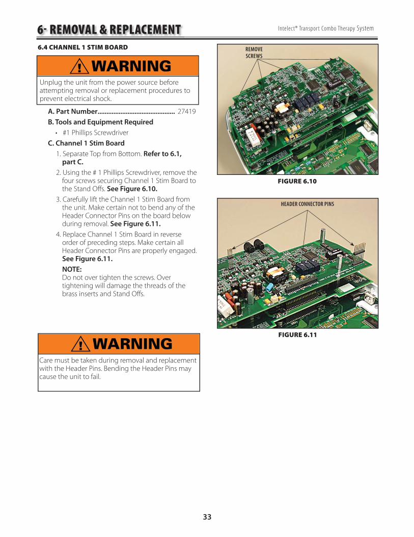
6.4 CHANNEL 1 STIM BOARD
A. Part Number ............................................ 27419
B. Tools and Equipment Required
#1 Phillips Screwdriver
C. Channel 1 Stim Board
1. Separate Top from Bottom. Refer to 6.1, part C.
2. Using the # 1 Phillips Screwdriver, remove the four screws securing Channel 1 Stim Board to the Stand Offs. See Figure 6.10.
3. Carefully lift the Channel 1 Stim Board from the unit. Make certain not to bend any of the Header Connector Pins on the board below during removal. See Figure 6.11.
4. Replace Channel 1 Stim Board in reverse order of preceding steps. Make certain all Header Connector Pins are properly engaged. See Figure 6.11.
NOTE: Do not over tighten the screws. Over tightening will damage the threads of the brass inserts and Stand Offs.
•
6- REMOVAL & REPLACEMENT
REMOVESCREWS
HEADER CONNECTOR PINS
FIGURE 6.10
FIGURE 6.11
Unplug the unit from the power source before attempting removal or replacement procedures to prevent electrical shock.
Care must be taken during removal and replacement with the Header Pins. Bending the Header Pins may cause the unit to fail.

34
Intelect® Transpor t Combo Therapy System
6.5 CHANNEL 2 STIM BOARD
A. Part Number ............................................. 27498
B. Tools and Equipment Required
#1 Phillips Screwdriver
1/4" Nut Driver or Wrench
C. Channel 2 Stim Board Removal
1. Separate Top from Bottom. Refer to 6.1, part C.
2. Remove Channel 1 Stim Board. Refer to 6.4, part C.
3. Using the 1/4" Nut Driver, remove the four Stand Offs securing Channel 2 Stim Board in place. See Figure 6.12.
4. Remove the 40 Pin Header from the back of the Channel 2 Stim Board. See Figure 6.13.
5 Install 40 Pin Header to back of new Channel 2 Stim Board. Make certain it is completely seated against board. See Figure 6.13.
6. Position the Channel 2 Stim Board over the Ultrasound Board aligning the 40 Pin Header with the 40 Pin Connector. See Figure 6.14.
7. Press the Channel 2 Stim Board into position until the board rests against the Ultrasound Board Stand Offs.
8. Secure the Channel 2 Stim Board using the Stand Offs removed in part C, step 3 above.
9. Install the Channel 1 Stim Board. Refer to 6.4, part C.
10. Re-assemble Top to Bottom. Refer to 6.1, part C.
NOTE: Do not over tighten the Stand Offs orScrews. Over tightening will damage the threads of the Brass Inserts and Stand Offs.
•
•
6- REMOVAL & REPLACEMENT
FIGURE 6.12
FIGURE 6.13
Unplug the unit from the power source before attempting removal or replacement procedures to prevent electrical shock.
FIGURE 6.15
REMOVE STANDOFFS
REMOVE 40 PIN HEADER
ALIGN HEADER TO CONNECTOR
Care must be taken during removal and replacement with the Header Pins. Bending the Header Pins may cause the unit to fail.

35
Intelect® Transpor t Combo Therapy System
6.6 ULTRASOUND BOARD
A. Part Number ............................................ 27269
B. Tools and Equipment Required
#1 Phillips Screwdriver
1/4" Nut Driver or Wrench C. Ultrasound Board
1. Separate Top from Bottom. Refer to 6.1, part C.
2. Remove Channel 1 Stim Board. Refer to 6.4, part C.
3. Remove Channel 2 Stim Board. Refer to 6.5, part C.
4. Using the 1/4" Nut Driver, remove the four Stand Offs securing Ultrasound Board in place. See Figure 6.15.
5. Carefully remove the Ultrasound Board. See Figure 6.16.
NOTE: Headers may stay on the board being removed or on the connector. If the header stays with the connector, remove and install on the replacement board.
6. Remove the 40 Pin Header from the Ultrasound Board or the connector. See Figure 6.16.
7. Install 40 Pin Header to back of new Ultrasound Board. Make certain it is completely seated against board. See Figure 6.17.
8. Position the Ultrasound Board over the Control Board aligning the 40 Pin Header with the 40 Pin Connector on Control Board. See Figure 6.16.
9. Press the Ultrasound Board into position until the board rests against the Control Board Stand Offs. Verify that it is well seated by pushing on the sides of the connector.
10. Secure the Ultrasound Board using the Stand Offs removed in part B, step 4 above.
11. Reassemble by reversing steps 1 through 3.
•
•
6- REMOVAL & REPLACEMENT
FIGURE 6.15
FIGURE 6.16
Unplug the unit from the power source before attempting removal or replacement procedures to prevent electrical shock.
FIGURE 6.17
REMOVE STANDOFFS
CONTROL BOARD CONNECTOR
INSTALL HEADER TO BACK OF ULTRASOUND BOARD
CONTROL BOARD HEADER
Care must be taken during removal and replacement with the Header Pins. Bending the Header Pins may cause the unit to fail.

36
Intelect® Transpor t Combo Therapy System
6.7 CONTROL BOARD ASSEMBLY
A. Part Number .............................................. 27249
B. Tools and Equipment Required
#1 Phillips Screwdriver
1/4" Nut Driver or Wrench
C. Control Board Replacement
1. Separate Top from Bottom. Refer to 6.1, part C.
2. Remove Channel 1 Stim Board. Refer to 6.4, part C.
3. Remove Channel 2 Stim Board. Refer to 6.5, part C.
4. Remove Ultrasound Board, Refer to 6.6, part C.
5. Remove the Contrast Control Knob. See Figure 6.18.
6. Remove the seven screws securing the Control Board Assembly in position. See Figure 6.19.
7. Remove the four LCD Bracket Mounting Screws. See Figure 6.21.
8. While lifting on the lower end of the Control Board Assembly with one hand, release the four Tabs securing the Control Board with the other, to remove the Control Board from the system Top. Two of the Tabs are located above the LCD and two below. See Figures 6.19 and 6.20.
•
•
6- REMOVAL & REPLACEMENT
FIGURE 6.18
FIGURE 6.19
Unplug the unit from the power source before attempting removal or replacement procedures to prevent electrical shock.
FIGURE 6.20
REMOVE CONTRAST KNOB
REMOVE SCREWS
REMOVE SCREWS
LIFT HERE
RELEASE TABS
CONTROL BOARDTABS ABOVE LCD

37
Intelect® Transpor t Combo Therapy System
9. On the back side of the Control Board, press down and back on the four LCD tabs and push back through the Control Board. See Figure 6.21.
10. On the front side of the Control Board, pull the LCD up to release the header from the board. See Figure 6.22.
11. Position the new Control Board Assembly over the Alignment Tabs of the system Top. Press the Control Board Assembly until the Alignment Tabs lock the Control Board into position.
12. Reverse steps 1 through 10 to install the replacement Control Board.
NOTE: Do not over tighten the Stand Offs or screws. Over tightening will damage the threads of the brass inserts and Stand Offs.
6- REMOVAL & REPLACEMENT6.7 CONTROL BOARD ASSEMBLY (CONTINUED)
LCD TABS
FIGURE 6.21
FIGURE 6.22
LCD HEADERPIN

38
Intelect® Transpor t Combo Therapy System6- REMOVAL & REPLACEMENT6.8 LCD
A. Part Number .............................................. 27249
B. Tools and Equipment Required
#1 Phillips Screwdriver
1/4" Nut Driver or Wrench
C. LCD Replacement
1. Separate Top from Bottom. Refer to 6.1, part C.
2. Remove Channel 1 Stim Board. Refer to 6.4, part C.
3. Remove Channel 2 Stim Board. Refer to 6.5, part C.
4. Remove Ultrasound Board, Refer to 6.6, part C.
5. Remove Control Board, Refer to 6.7, part C steps 1 through 10.
6. Once the LCD is removed from the Control Board, per step 5, remove the LCD mounting bracket from both sides of the LCD. See Figure 6.23.
7. Replace the LCD by reversing the steps above.
NOTE: Always install the LCD Brackets prior to attaching the LCD to the Control Board.
•
•
FIGURE 6.23
LCD MOUNTINGBRACKETS

39
Intelect® Transpor t Combo Therapy System
A. Part Number
KeyMat and On/Off Button ....................27560
B. Tools and Equipment Required
#1 Phillips Screwdriver
1/4 in Wrench
B. Keymat Assembly Removal
1. Separate Top from Bottom. Refer to 6.1, part C.
2. Remove Channel 1 Stim Board. Refer to 6.4, part C.
3. Remove Channel 2 Stim Board. Refer to 6.5, part C.
4. Remove Ultrasound Board. Refer to 6.6, part C.
5. Remove Control Board Assembly. Refer to 6.7, part C.
6. Lift out Keymat Assembly or On/Off Button KeyMat. See Figure 6.24.
7. Replace the KeyMat by reversing steps 1 through 6.
NOTE: Do not over tighten the Stand Offs or screws. Over tightening will damage the threads of the brass inserts and Stand Offs.
•
•
6- REMOVAL & REPLACEMENT
FIGURE 6.24
Unplug the unit from the power source before attempting removal or replacement procedures to prevent electrical shock.
6.9 KEYMAT, ON/OFF BUTTON, OR UNIT TOP
KEYMAT
ON/OFF BUTTON

40
Intelect® Transpor t Combo Therapy System
A. Part Number
Plynth .........................................................27253
B. Tools and Equipment Required
none
B. Plynth Removal
NOTE:
The plynth is secured to the unit by tabs that fit into the five slots shown in Figure 6.25.
1. Remove the Plynth by applying pressure to center of the top or wide part of the Plynth. When pressing lift the Plynth out the three slots at the top and then remove the Plynth from the two slots at the bottom. Refer to 6.26.
7. Replace the Plynth by reversing this procedure.
•
6- REMOVAL & REPLACEMENT
FIGURE 6.25
6.10 PLYNTH
FIGURE 6.26
PLYNTH MOUNTINGSLOTS

41
Intelect® Transpor t Combo Therapy System
7.1 CLEANING THE SYSTEM A. Cleaning the Therapy System
With the system disconnected from the power source, clean the system with a clean, lint free cloth moistened with water and mild antibacterial soap. If a more sterile cleaning is needed, use a cloth moistened with an antimicrobial cleaner.
Do not submerse the system in liquids. Should the unit accidentally become submersed, contact the dealer or Chattanooga Group Service Department immediately. Do not attempt to use a system that has been wet inside until inspected and tested by a Service Technician Certified by Chattanooga Group.
Do not allow liquids to enter the ventilation holes in the optional modules. This could permanently damage the modules.
B. Cleaning Therapy System Lens
Clean the Therapy System Lens with the NOVUS® Plastic Polishing System. NOVUS can be purchased by going to www.novuspolish. com on the internet. Follow the instructions as given by NOVUS on their product.
Do Not Use alcohol or chlorine based solvents as this may damage the lens.
7.2 CALIBRATION REQUIREMENTS Ultrasound Applicators: Annual calibration is required for all Ultrasound Applicators. Only the Applicators should be sent to the factory or a Field Technician certified by Chattanooga Group for this procedure.
7.3 FIELD SERVICE A. All field service procedures as described in this Service Manual must be performed by a Service Technician certified by Chattanooga Group.
B. Any attempted outside the scope of this Service Manual is the sole responsibility and liability of the Field Technician performing such procedures.
C. After the performance of any Field Service, perform the tests as described in 5.3 through 5.16 to verify the system operates properly and within specifications prior to placing the unit back into operation.
7.4 FACTORY SERVICE When the Intelect Transport Combo Therapy System requires factory service, contact the dealer or Chattanooga Group Service Department.
7- GENERAL MAINTENANCE

42
Intelect® Transpor t Combo Therapy System
8.1 GENERAL PROCEDURES A. Tools and Equipment Required
All Ultrasound Applicators for the unit being serviced.
Ohmic Instruments UPM DT 10 or UPM DT 100 Ultrasound Power Meter, set to "Watts".
Degassed Water. Refer to page 16 for Degassed Water Recipes.
B. Ultrasound Applicator Calibration Procedures
1. Perform the following on all Ultrasound Applicators for the unit being serviced at least annually.
2. With the system on, press the Clinical Resources button once. See Figure 8.1.
3. Simultaneously press and hold the Treatment Time and Intensity Decrease buttons for approximately 2 seconds. See Figure 8.2. The calibration procedures screen should display.
4. Press the Down Arrow button until US Applicator Calibration is highlighted.
5. Press the Enter button.
6. Place the Ultrasound Applicator being calibrated into the Ohmic Instruments UPM UPM DT 100 or DT 10 Ultrasound Power Meter and set meter to "Watts”. See Figure 8.3.
7. Follow the instructions on the LCD Display.
8. When calibration is complete, follow the test procedures in 5.13 and 5.14 to verify that the Applicator is calibrated..
•
•
•
FIGURE 8.3
FIGURE 8.1
FIGURE 8.2
SET METER TO WATTS
8- ULTRASOUND APPLICATOR CALIBRATION
Use only Degassed Water in Power Meter for calibrating Ultrasound Applicators.
Use of other types of water will cause false readings and bad test results.
See page 16 for Degassed Water Recipes.
Use of other brands or types of tools, equipment, fixtures, materials, and supplies other than those specifically listed on page 16 will give bad test and calibration results.
If proper equipment is not available or cannot be obtained, send the Ultrasound Applicators to the factory for calibration.
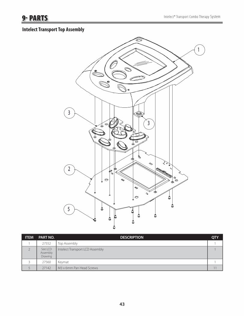
43
Intelect® Transpor t Combo Therapy System
Intelect Transport Top Assembly
ITEM PART NO. DESCRIPTION QTY
1 27552 Top Assembly 1
2 See LCD
Assembly
Drawing
Intelect Transport LCD Assembly 1
3 27560 Keymat 1
5 27142 M3 x 6mm Pan Head Screws 11
9- PARTS
3
5
2
3
1

44
Intelect® Transpor t Combo Therapy System
Intelect Transport Ultrasound and Stim Boards
ITEM PART NO. DESCRIPTION QTY
1 See Top
Assembly
Drawing
Intelect Transport Top Assembly 1
2 28019 Header 1
3 27269 Ultrasound PCB 1
4 28020 Connector 1
5 27498 Channel 2 Stim PCB 1
6 28017 Standoff M3 x 19mm 4
7 27419 Channel 1 Stim PCB 1
8 27770 Standoff M3 x 16mm 4
9 27142 M3 x 6mm Pan Head Screws 4
9- PARTS
NOTE: INSERT #3 LONG PINS DOWN, INTO PCB #2 FIRST, NOTE: INSERT #3 LONG PINS DOWN, INTO PCB #2 FIRST, THEN INTO #1THEN INTO #1
1
3
5
7
2
6
8
9
4

45
Intelect® Transpor t Combo Therapy System
Intelect Transport LCD Assembly
ITEM PART NO. DESCRIPTION QTY
1 27249 PCB Assembly 1
2 27261 LCD Spacer 2
3 27012 Contrast Knob 1
4 27264 LCD 1
5 27588 Header 1
9- PARTS
1
3
NOTE: INSERT #4 THROUGH TOP NOTE: INSERT #4 THROUGH TOP ROW OF SOCKET CONNECTOR OF #1ROW OF SOCKET CONNECTOR OF #1
2
4
1 2 3 4
ONONONONONONONON
DIP SWITCH NODIP SWITCH NO
DIM SWITCH POSITIONSDIM SWITCH POSITIONS
5
INSERT LONG END OF HEADER UP FROM BOTTOM OF DISPLAY. SOLDER TO DISPLAYINSERT LONG END OF HEADER UP FROM BOTTOM OF DISPLAY. SOLDER TO DISPLAY

46
Intelect® Transpor t Combo Therapy System
Intelect Transport Base Assembly
ITEM PART NO. DESCRIPTION QTY
1 27983 Base Deep 1
2 27256 Applicator Hang-Up 1
3 27984 Connector Infi ll Panel 1
4 27367 Fan Seal 1
5 27265 Power Supply 1
6 27158 Fan 1
7 27152 Snap in Inlet (IEC Socket) 1
9 27136 M4 x 35mm 2
10 27142 M3 x 6mm 2
11 27592 Shield T-Port Power Supply 1
9- PARTS
DETAIL A (SEE FIGURE 6.9) DETAIL A (SEE FIGURE 6.9)
BLUE
WIRE
BLUE
WIRE
RED W
IRERE
D WIRE
NL
SEE DETAIL ASEE DETAIL A
NOTENOTETUCK FERRITETUCK FERRITEUNDER POWER UNDER POWER SUPPLYSUPPLY
TUCK FERRITETUCK FERRITEUNDER POWER UNDER POWER SUPPLY AND INTO CORNERSUPPLY AND INTO CORNER
PLACE INSULATED SIDE OF SHIELD NEXT TO PLACE INSULATED SIDE OF SHIELD NEXT TO POWER SUPPLYPOWER SUPPLY
94
5
1010
1111
6
3
1
2
7
GRE
EN W
ITH
YEL
LOW
STR
IPE
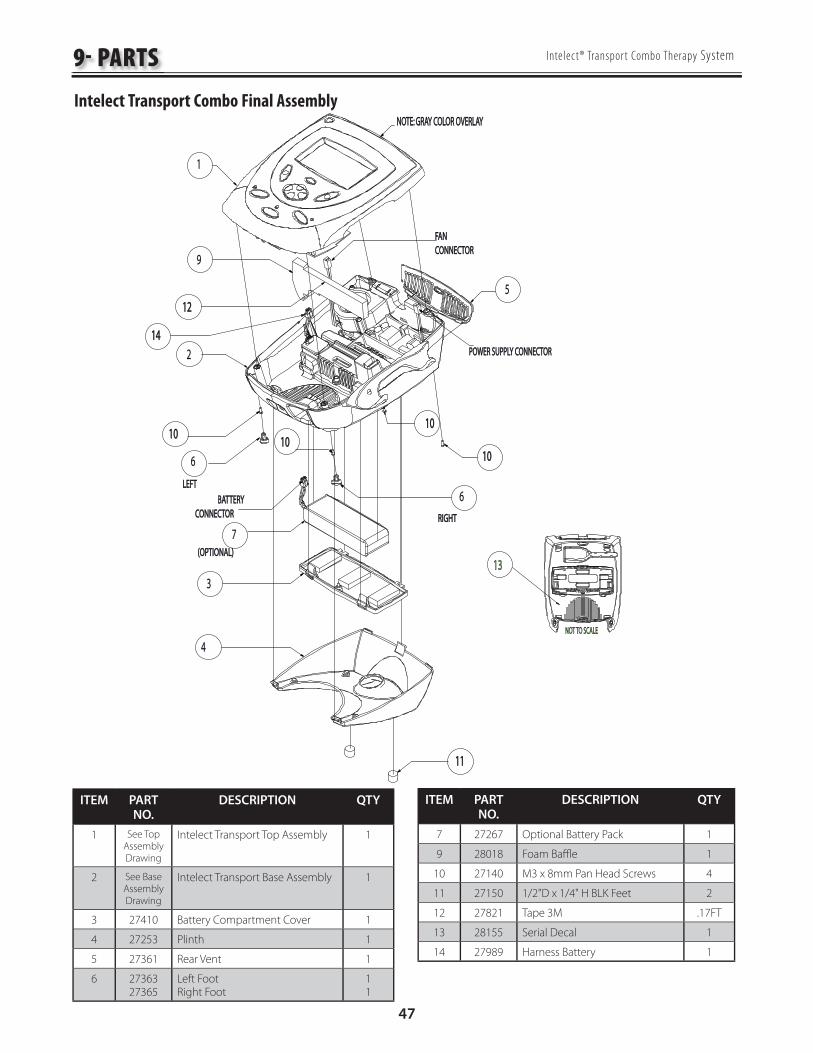
47
Intelect® Transpor t Combo Therapy System
Intelect Transport Combo Final Assembly
9- PARTS
ITEM PART NO.
DESCRIPTION QTY
1 See Top
Assembly
Drawing
Intelect Transport Top Assembly 1
2 See Base
Assembly
Drawing
Intelect Transport Base Assembly 1
3 27410 Battery Compartment Cover 1
4 27253 Plinth 1
5 27361 Rear Vent 1
6 2736327365
Left FootRight Foot
11
1313
6
3
4
BATTERYBATTERYCONNECTORCONNECTOR
7RIGHTRIGHT
10101010
1010
2
9
FANFANCONNECTORCONNECTOR
POWER SUPPLY CONNECTORPOWER SUPPLY CONNECTOR
5
1
1111
NOTE: GRAY COLOR OVERLAYNOTE: GRAY COLOR OVERLAY
1212
1010
6
1414
LEFTLEFT
(OPTIONAL)(OPTIONAL)
NOT TO SCALENOT TO SCALE
ITEM PART NO.
DESCRIPTION QTY
7 27267 Optional Battery Pack 1
9 28018 Foam Baffl e 1
10 27140 M3 x 8mm Pan Head Screws 4
11 27150 1/2"D x 1/4" H BLK Feet 2
12 27821 Tape 3M .17FT
13 28155 Serial Decal 1
14 27989 Harness Battery 1

10- SCHEMATICS
48
Intelect® TranSpor t Combo Therapy System
12
C1C1100pF/100V100pF/100V
12
C5C50.1uF/200V0.1uF/200V
12
C6C60.1uF/200V0.1uF/200V
12
C18C180.1uF0.1uF
12
C2C2100pF/100V100pF/100V
1
43
Q4Q4IRLR110IRLR110
14
3
Q7Q7IRLR110IRLR110
12
R10R101.0M1.0M
12
R2R24747
12
R1R14747
12
R11R111.0M1.0M
1 2R9R9
2.22.2
1 2
R12R122.22.2
12
C3C34.7uF/25V4.7uF/25V
1
TP1TP1TESTPOINTTESTPOINT
21
3D3D3BAS16BAS16
1 2
C9C92200pF/250V2200pF/250V
12
L1L111.5uH/2A11.5uH/2A
1
32
Q8Q82N70022N7002
43
5
91010
81
1212
K1K1
TX2-24VTX2-24V
1 2
C10C101000pF/250V1000pF/250V
12
L2L22.8uH/2A2.8uH/2A
12
R13R1310K10K
12
R112R1120
12
R18R18
1.00K1.00K
12
C13C1310nF10nF
12
R7R7100100
12
R8R8100100
12
C14C1410nF10nF
S1S1S1S1
S2S2S2S2
S3S3S3S3
11
22
33
44
55
66
77
88 J1J1
KMDG-8S-BSKMDG-8S-BS
12
R17R17
14.0K14.0K
12
C21C21
0.1uF0.1uF1 2
R21R21
1.00K1.00K
12
R20R20300K_NL300K_NL
12
C22C22
0.1uF0.1uF
12
R19R19
1.5K_NL1.5K_NL
12
C19C19
0.1uF0.1uF
12
C20C200.1uF_NL0.1uF_NL
1 2
L4L4100uH_NL100uH_NL
12
R23R230_NL0_NL
12
C23C230.1uF_NL0.1uF_NL
1 2R22R22
1.5K_NL1.5K_NL
VDDVDD1
GNDGND2
ININ3
VCCVCC5
OUTOUT4
U2U2
TPS2819DBVTPS2819DBV
+
-
3
26
74
U4U4
LMH6642MALMH6642MA
12
C16C164.7uF/25V4.7uF/25V
FB1FB1HZ1206HZ1206
12
C15C150.1uF0.1uF
+40VADJ+40VADJ
VCCVCC
VCCVCC
GNDGND
GNDGND
VINVIN
GNDGND
GNDGND
GNDGND
GNDGND
VCCVCC
-5V-5V
GNDGND
GNDGND
VCCVCC
US_GNDUS_GND
US_GNDUS_GND
IRFIRF
1_3MHZ1_3MHZ
HEAD
_CLOC
KHE
AD_CL
OCK
HEAD
_DATA
HEAD
_DATA
VRFVRF
HEAD_DETECTHEAD_DETECT
SOUNDHEAD CONNECTORSOUNDHEAD CONNECTOR
1 2
L3L3100uH100uH
12
C4C433uF/63V33uF/63V
4
3
5
6
81
2 7
T1T1
ENG00787ENG00787
12
C11C114.7uF/25V4.7uF/25V
12
C12C120.1uF0.1uF
GNDGND
GNDGND
12
C98C98
NLNL
GNDGNDGNDGND
GNDGND
FB10FB10
HZ1206HZ1206
FB9FB9
HZ1206HZ1206
R151R151
0
R152R152
012
R160R16022_NL22_NL
VDDVDD1
GNDGND2
ININ3
VCCVCC5
OUTOUT4
U3U3
TPS2819DBVTPS2819DBV
GNDGND
1 2C29C29
0.1uF0.1uF
12
R27R27
62062012
R25R252.2K2.2K
12
R26R262.2K2.2K
12
C25C250.1uF0.1uF
12
C27C270.1uF0.1uF
FBKFBK1313
LOCK/IPRGLOCK/IPRG9
EXTLFEXTLF1010
VSSVSS1111
CLKNCLKN1616
VDDVDD1414
REFREF1212
CLKPCLKP1515
VDDVDD8
VSSVSS4
ADDR1ADDR17
XOUTXOUT6
XINXIN5
ADDR0ADDR03
SDASDA2
SCLSCL1
U5U5
FS6131-01FS6131-01
12
C28C28
39pF39pF
12
R28R28620620
1 2
C17C17
39pF39pF
FB2FB2
HZ1206HZ1206
12
C26C264.7uF/25V4.7uF/25V
VCCVCC
GNDGND VCCVCCGNDGND
GNDGND
GNDGND GNDGND
GNDGND
GNDGND
GNDGND
VCCVCC
GNDGND
GNDGND
DUTY_CYCLEDUTY_CYCLE
I2C_DATAI2C_DATAI2C_CLOCKI2C_CLOCK
1
TP14TP14
TESTPOINTTESTPOINT
GNDGND
345
6
U1BU1B
74HC27D74HC27D
121313
1212
U1AU1A
74HC27D74HC27D
910101111
8
14147
U1CU1C
74HC27D74HC27D
GNDGND
US GroundUS Ground
12
R5R50.560.56
43
5
91010
811212
K2K2
TX2-24VTX2-24V
GNDGND
1 2
L9L910uH10uH
1 2
L10L1010uH10uH
OUTOUT3
VCCVCC4
EOHEOH1
GNDGND2
OSC1OSC1
OSCILLATOROSCILLATORC103C103
.01uF 50V.01uF 50VGNDGND VCCVCC
GNDGND
Ultrasound Board
1 of 3 (AMP)
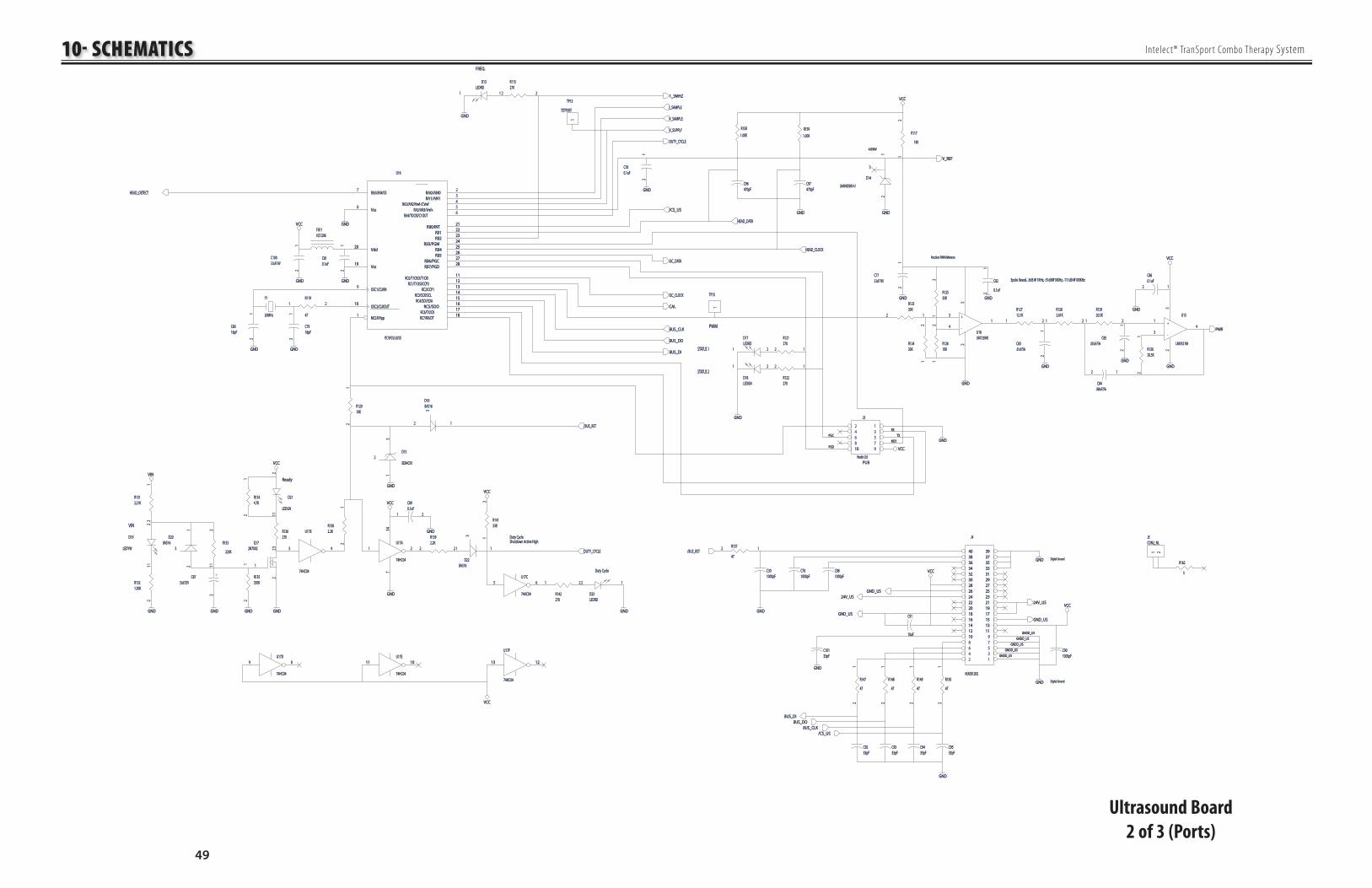
10- SCHEMATICS
49
Intelect® TranSpor t Combo Therapy System
PGCPGC
PGDPGD
Y1Y1
20MHz20MHz
21
3
D14D14
LM4040DIM3-4.1LM4040DIM3-4.1
5 6U17CU17C
74HC0474HC04
1 2
14147
U17AU17A
74HC0474HC04
12
C81C810.1uF0.1uF
12
C85C85.033uF/5%.033uF/5%
12
C83C83.01uF/5%.01uF/5%
12
C76C760.1uF0.1uF
12
C84C84.068uF/5%.068uF/5%
12
C82C82
0.1uF0.1uF12
C86C860.1uF0.1uF
21
3
D20D20BAS16BAS16
2 1
3
D22D22BAS16BAS16
1 2R119R119
4747 12
R123R12333K33K
1 2
R129R12920.5K20.5K
1 2
R127R12712.1K12.1K
12
R133R133
220K220K12
R139R1392.2K2.2K
1 2
R128R1282.61K2.61K
12
R124R12433K33K
+
-
3
41
52
U18U18LMV7239M5LMV7239M5
12
R125R12533K33K
+
-
1
34
52
U15U15
LMV321MLMV321M
12
R126R12610K10K
12
R136R136270270
12
C87C8733uF/25V33uF/25V
3 4
U17BU17B
74HC0474HC04
12
R135R135330K330K
1
32
Q17Q172N70022N7002
21
D21D21
LEDGNLEDGN
12
R117R117
180180
12
R132R1321.00K1.00K
21
D19D19
LEDYWLEDYW
12
R134R1344.7K4.7K
2 1
D23D23LEDRDLEDRD
12
R141R14133K33K
12
R131R1312.21K2.21K
12
R120R12010K10K
1 2
R142R142270270
13
2D15D15
BZX84C5V1BZX84C5V1
2 13
D16D16BAS16BAS16
12
C80C8018pF18pF
12
C79C7918pF18pF
12
R130R13020.5K20.5K
12
R150R150
4747
1234567891010
111112121313141415151616171718181919202021212222232324242525262627272828292930303131323233333434353536363737383839394040
J4J4
HEADER 20X2HEADER 20X2
12
R147R147
4747
12
R148R148
4747
1 2
J5J5CON2_NLCON2_NL
12
R149R149
4747
12 R137R137
4747
MCLR/VppMCLR/Vpp1
RA0/AN0RA0/AN02
RA1/AN1RA1/AN13
RA2/AN2/Vref-/CVrefRA2/AN2/Vref-/CVref4
RA3/AN3/Vref+RA3/AN3/Vref+5
RA4/TOCKI/C1OUTRA4/TOCKI/C1OUT6
VssVss8
OSC1/CLKINOSC1/CLKIN9
OSC2/CLKOUTOSC2/CLKOUT1010
RC0/T1OSO/T1CKIRC0/T1OSO/T1CKI1111
RC1/T1OSI/CCP2RC1/T1OSI/CCP21212
RC2/CCP1RC2/CCP11313
RC3/SCK/SCLRC3/SCK/SCL1414
RC4/SDI/SDARC4/SDI/SDA1515
RC5/SDORC5/SDO1616
RC6/TX/CKRC6/TX/CK1717
RC7/RX/DTRC7/RX/DT1818
VssVss1919
VddVdd2020
RB0/INTRB0/INT2121
RB1RB12222
RB2RB22323
RB3/PGMRB3/PGM2424
RB4RB42525
RB5RB52626
RB6/PGCRB6/PGC2727
RB7/PGDRB7/PGD2828
RA5/AN4/SSRA5/AN4/SS7
U16U16
PIC18F252-20/SOPIC18F252-20/SO
21
D13D13LEDRDLEDRD
1 2
R115R115270270
1 2
C89C890.1uF0.1uF1
2
R138R1382.2K2.2K
GNDGND
GNDGNDGNDGND
GNDGND
GNDGND
GNDGND
GNDGND
VCCVCC
GNDGND
GNDGND
GNDGND
GNDGND
VCCVCC
GNDGND
VCCVCC
GNDGND GNDGND
VCCVCC
VINVIN
GNDGND
VCCVCC
GNDGNDGNDGND
GNDGND
GNDGND
GNDGND
GNDGND
DUTY_CYCLEDUTY_CYCLE
V_SAMPLEV_SAMPLE
DUTY_CYCLEDUTY_CYCLE
CALCAL
/CS_US/CS_US
BUS_CLKBUS_CLK
/BUS_RST/BUS_RST
BUS_DIBUS_DI
BUS_DOBUS_DO
1_3MHZ1_3MHZ
HEAD_DETECTHEAD_DETECT
V_SUPPLYV_SUPPLY
I_SAMPLEI_SAMPLE
PWRPWR
V_REFV_REF
GND_USGND_US
24V_US24V_US
GND_USGND_US
24V_US24V_US
/CS_US/CS_US
GND_USGND_US
BUS_CLKBUS_CLKBUS_DOBUS_DO
BUS_DIBUS_DI
/BUS_RST/BUS_RST
3pole Bessel, -3dB @ 1KHz, -51dB@10KHz, -111dB @100KHz3pole Bessel, -3dB @ 1KHz, -51dB@10KHz, -111dB @100KHz
Precision PWM ReferencePrecision PWM Reference
ReadyReady
Duty CycleDuty Cycle
4.096V4.096V
Shutdown Active HighShutdown Active High
Duty CycleDuty Cycle
FREQ.FREQ.
GNDD_USGNDD_US
GNDD_USGNDD_US
GNDD_USGNDD_US
GNDD_USGNDD_US
GNDD_USGNDD_US
I2C_DATAI2C_DATA
I2C_CLOCKI2C_CLOCK
GNDGND Digital GroundDigital Ground
GNDGND
R158R158
1.00K1.00K
C96C96470pF470pF
C97C97470pF470pF
R159R159
1.00K1.00K
GNDGND
9 8U17DU17D
74HC0474HC04
1111 1010U17EU17E
74HC0474HC04
VCCVCC
1234567891010
J3J3
Header 2x5Header 2x5
GNDGND
RXRX
TXTX
MD1MD1
PUBPUB
HEAD_CLOCKHEAD_CLOCK
HEAD_DATAHEAD_DATA
GNDGND Digital GroundDigital Ground
1313 1212
U17FU17F
74HC0474HC04
VCCVCC
1
TP15TP15
PWMPWM
12
R121R121270270
21
D18D18LEDGNLEDGN
21
D17D17LEDRDLEDRD
12
R122R122270270
GNDGND
STATUS 1STATUS 1
STATUS 2STATUS 2
VINVIN
1
TP13TP13
TESTPOINTTESTPOINT
VCCVCC
VCCVCC
12
C77C773.3uF/16V3.3uF/16V
FB11FB11HZ1206HZ1206
VCCVCC
GNDGND
R162R162
0
12
C100C1003.3uF/16V3.3uF/16V
C92C9233pF33pF
C93C9333pF33pF
C94C9433pF33pF
C95C9533pF33pF
GNDGND
C30C301000pF1000pF
C78C781000pF1000pF
C88C881000pF1000pF
GNDGND
C101C10133pF33pF
C91C91
10uF10uF
C90C901000pF1000pF
GNDGND
Ultrasound Board
2 of 3 (Ports)

10- SCHEMATICS
50
Intelect® TranSpor t Combo Therapy System
DD
C
21
D8D8
MBRS1
100MB
RS1100
21
D10D10
MBRS1
100MB
RS1100
12
C52C520.1uF/200V0.1uF/200V
12
C60C6010nF10nF
12
C33C3318pF_NL18pF_NL
12
C43C4318pF_NL18pF_NL
12
C47C471nF/100V1nF/100V
12
C66C661nF/100V1nF/100V
FB4FB4HZ1206HZ1206
12
R60R60200200
12
R90R90200200
12
R86R86
4747
12
R84R84
4.99K4.99K
12
R80R804.99K4.99K
12
R91R91200200
12
R61R61200200
1 2
R30R301.00K1.00K
1 2R31R31
1.00K1.00K
1 2
R50R501.00K1.00K
1 2R51R51
1.00K1.00K
1 2
R54R542.00K2.00K
12
R34R342.00K2.00K
12
R33R33
1.00K1.00K
1 2
R36R36499499
12
R53R531.00K1.00K
12
R93R93
2.22.2
12
R92R921.0M1.0M
2
1
34
Q16Q16NDT3055LNDT3055L
12
C73C73100pF100pF
1
23
Q14Q14MMBT3906MMBT39061
23
Q13Q13MMBT3906MMBT3906
12
R35R35
2.00K2.00K
12
R55R552.00K2.00K
+
-
1212
13131414
U7DU7DLMH6644MALMH6644MA
+
-
5
67
U7BU7BLMH6644MALMH6644MA
1
TP6TP6
TESTPOINTTESTPOINT
1
TP7TP7TESTPOINTTESTPOINT
12
R95R9518.0K18.0K
12
R89R890.100 Ohm0.100 Ohm
1 2
R39R391.47K1.47K
1 2
R37R37301301
+
-
1010
98
U7CU7CLMH6644MALMH6644MA
1 2
R56R56499499
1 2
R57R57301301
1 2
R59R594.02K4.02K
12
C46C464.7nF4.7nF
12
C35C3522nF22nF
COMPCOMP1
FBFB2
CSCS3
RCRC4
GNDGND5
OUTBOUTB6
OUTAOUTA7
VDDVDD8
U13U13
UCC3808AN-2UCC3808AN-2
+
-
3
21
41111
U7AU7ALMH6644MALMH6644MA
12
R110R110
9.09K9.09K
1 2
R52R52499499
1 2
R29R29499499
1 2
C61C61
560pF560pF
1 2
R58R581.00K1.00K
12
C44C4433nF33nF
1 2
R32R32499499
FB3FB3HZ1206HZ1206
1 2
C32C320.1uF0.1uF
1 2
C31C310.1uF0.1uF
12
C69C690.1uF0.1uF
12
C53C530.1uF0.1uF
12
C68C680.1uF0.1uF
1 2
R49R49499499
12
C54C540.1uF0.1uF
12
C42C420.1uF0.1uF
12
R96R962.00K2.00K
12
C41C410.1uF0.1uF
12
R109R109
220K220K
1 2
R38R382.00K2.00K
+
-
1
34
52
U14U14LMV321MLMV321M
12
C34C3433nF33nF
ININ1
V+V+2
GNDGND3
COMCOM5
NONO6
NCNC4
U8U8
MAX4644EUTMAX4644EUT
12
C45C450.1uF0.1uF
12
C75C754.7uF/35V4.7uF/35V
12
C74C740.1uF0.1uF
1
TP11TP11TESTPOINTTESTPOINT
1
TP12TP12TESTPOINTTESTPOINT
1
TP3TP3
TESTPOINTTESTPOINT
1 2R108R108
2.2K2.2K
FB5FB5FERRITEFERRITE
FB6FB6FERRITEFERRITE
2
1
3
D4D4BAT54SBAT54S
2
1
3
D7D7BAT54SBAT54S
1 2R67R67
29.4K29.4K
1 2R65R65
4.99K4.99K
1 2R74R74
6.81K6.81K
12
R107R1073.32K3.32K
12
R72R721.78K1.78K
12
R75R75511511
V+V+8
OUTOUT5
CAP-
CAP-
4
LVLV6
GND
GND
3
FCFC1
CAP+
CAP+
2
OSC
OSC
7
U12U12
MAX660MMAX660M
12R66R66
4.99K4.99K
12
C63C634.7uF/25V4.7uF/25V
12
R88R881.0M1.0M
2
1
34
Q15Q15NDT3055LNDT3055L
12
C64C640.1uF0.1uF
12
C67C670.1uF/50V0.1uF/50V
1
32
Q9Q92N70022N7002
12
R99R991.0M1.0M
12
C70C70NLNL
12
R64R64
4747
1 2R71R71
649649
12
R73R73
4747
1
32
Q10Q102N70022N7002
12
R76R761.0M1.0M
12
C58C581nF_NL1nF_NL
1
TP10TP10TESTPOINTTESTPOINT
12
C65C65680uF/35V680uF/35V
12
C48C480.1uF/50V0.1uF/50V
12
C55C55NLNL
1
TP8TP8TESTPOINTTESTPOINT
1
TP9TP9TESTPOINTTESTPOINT
+
-
3
21
41111
U9AU9A
LMV824MLMV824M
+
-
1212
13131414
U9DU9D
LMV824MLMV824M
+
-
5
67
U9BU9BLMV824MLMV824M
+
-
1010
98
U9CU9CLMV824MLMV824M
1 2R94R94
150150
L8L847uH47uH
1 2R63R63
150150
1 2
R62R62150150
1 2
C50C501nF/200V1nF/200V
12
R87R872.22.2
VCCVCC
+40VADJ+40VADJ
VINVIN
-5V-5V
GNDGND
GNDGND
GNDGND
GNDGND
GNDGND
VCCVCC
GNDGND
GNDGND
GNDGND
GNDGND
VCCVCC
GNDGND
GNDGND
GNDGND
GNDGND
VCCVCC
GNDGND
VINVIN
GNDGND
GNDGND
GNDGND GNDGND
GNDGNDGNDGND GNDGND
GNDGND GNDGND GNDGND
GNDGND
GNDGND
GNDGND GNDGND
GNDGND
VRFVRF
V_SUPPLYV_SUPPLY
IRFIRF
CALCAL
24V_US24V_US
GND_USGND_US
PWRPWR
V_REFV_REF
FEEDBKFEEDBK
I_SAMPLEI_SAMPLE
V_SAMPLEV_SAMPLE
DUTY_CYCLEDUTY_CYCLE
40 VOLT ADJUSTABLE SUPPLY40 VOLT ADJUSTABLE SUPPLY
0-0.300V (0-3A)0-0.300V (0-3A)
-5V SUPPLY-5V SUPPLY
VOUT- FULL-WAVE RECTIFIERVOUT- FULL-WAVE RECTIFIER
IOUT- FULL-WAVE RECTIFIERIOUT- FULL-WAVE RECTIFIER
50mA max.50mA max.
20 - 25.5 VDC20 - 25.5 VDC
Ground LinksGround Links
Analog GroundAnalog Ground
0- 4.1V0- 4.1V
4.096V4.096V
1 2
R68R681M_NL1M_NL
1 2
R69R69100_NL100_NL 1
2
C62C62470pF470pF
GNDGND
1 2
C57C57
10nF_NL10nF_NL
1
TP4TP4
TESTPOINTTESTPOINT
1
TP2TP2
TESTPOINTTESTPOINT
1
TP5TP5
TESTPOINTTESTPOINT
4
3
5
6
81
2 7
T3T3
ENG00789ENG00789
12
J6J6
CON2CON2
1 2
R161R16133K33K
12
C99C990.1uF0.1uF
GNDGND
12
C51C513.3uF/16V3.3uF/16V
12
C49C493.3uF/16V3.3uF/16V
VCCVCC
GNDGND
GNDGND
12
C37C370.1uF0.1uF
-5V-5V
VCCVCC12
C56C563.3uF/16V_NL3.3uF/16V_NL
GNDGND
12 R77R77
2.21K2.21K
GNDGND
GNDGND
REVREV E.N. NO.E.N. NO.B 1865318653C 1871018710D 1896518965E 1976719767
1
34
D24D24
RECTIFIERRECTIFIER
FB12FB12
Ultrasound Board
3 of 3 (V Supply)

10- SCHEMATICS
51
Intelect® TranSpor t Combo Therapy System
VDDVDD
Y1Y1
20MHz20MHzC2C222pf22pf
C3C322pf22pf
RSTRST1
VddVdd2
GNDGND3
U2U2
DS1233ADS1233A
VDDVDD
R8R8
10K10K
C1C1.01uf.01uf
1 23 45 67 89 10101111 12121313 14141515 16161717 18181919 20202121 22222323 24242525 26262727 28282929 30303131 32323333 34343535 36363737 38383939 4040
HDR1HDR1
HEADER 20X2HEADER 20X2
VSSVSSVSSVSSVSSVSSVSSVSSVSSVSS
VCCVCCVSSVSS+24V+24VVSSVSS+24V+24VVSSVSS
VSSVSS
VSSVSSVSSVSS
+24V+24V
+24V+24V
VSSVSSVSSVSSVSSVSSVSSVSS
CCCC
/BUS_RST/BUS_RST/CS_AUX_5V/CS_AUX_5V
VCCVCCVSSVSS
VSSVSS
VCCVCCCCCC
/CS_STIM_5V/CS_STIM_5V/CS_US_5V/CS_US_5VBUS_CLKBUS_CLKBUS_DOBUS_DOBUS_DIBUS_DI
DQDQ
AC_INAC_INSD_REQSD_REQ
/CS_STIM_5V/CS_STIM_5V/CS_US_5V/CS_US_5V/CS_AUX_5V/CS_AUX_5V
R20R20100K100K
Q1Q12N70022N7002
R9R910K10K
VCCVCC
/BUS_RST/BUS_RST
BEEPERBEEPERBATT_INBATT_IN
FAN
FAN
/EEPROM_CS/EEPROM_CS
Connector: Samtec TLE-120-01-G-DV-AConnector: Samtec TLE-120-01-G-DV-A
Vcc
Vcc
5
P3(0)P3(0)5959
P3(1)P3(1)6060
P3(2)P3(2)6161
P3(3)P3(3)6262
P3(4)P3(4)6363
P3(5)P3(5)6464
P2(0)P2(0)7979
P2(1)P2(1)7878
P2(2)P2(2)7777
P2(3)P2(3)7676
P2(4)P2(4)7575
P2(5)P2(5)7474
P2(6)P2(6)7373
P2(7)P2(7)7272
P1(0)P1(0)122122
P1(1)P1(1)121121
P1(2)P1(2)120120
P1(3)P1(3)119119
P1(4)P1(4)118118
P1(5)P1(5)117117
P1(6)P1(6)116116
P1(7)P1(7)115115
P4(0)P4(0)105105
P4(1)P4(1)106106
P4(2)P4(2)107107
P4(3)P4(3)108108
P4(4)P4(4)109109
P4(5)P4(5)110110
P4(6)P4(6)111111
P4(7)P4(7)112112
P5(0)P5(0)9797
P5(1)P5(1)9898
P5(2)P5(2)101101
P5(3)P5(3)102102
P6(0)
P6(0)
6666
P6(1)
P6(1)
6969
P6(2)
P6(2)
7070
P6(3)
P6(3)
7171
P6(4)
P6(4)
3838
P6(5)
P6(5)
3737
P6(6)
P6(6)
3434
P6(7)
P6(7)
3333
Vcc
Vcc
3939Vc
cVc
c5858
Vcc
Vcc
8484Vc
cVc
c8989
Vss
Vss
6565Vs
sVs
s5353
Vss
Vss
4444Vs
sVs
s3636
Vss
Vss
3535Vs
sVs
s2828
Vss
Vss
1919Vs
sVs
s1010
PA(4)/A20PA(4)/A202929
PA(5)/A21PA(5)/A213030
PA(6)/A22PA(6)/A223131
PA(0)/A16PA(0)/A162424
PA(1)/A17PA(1)/A172525
PA(2)/A18PA(2)/A182626
PA(3)/A19PA(3)/A192727
PB(0)/A8PB(0)/A81515
PB(1)/A9PB(1)/A91616
PB(2)/A10PB(2)/A101717
PB(3)/A11PB(3)/A111818
PB(4)/A12PB(4)/A122020
PB(5)/A13PB(5)/A132121
PF(0)
PF(0)
9696PF
(1)PF
(1)9595
PF(2)
PF(2)
9494PF
(3)PF
(3)9393
PF(4)
PF(4)
9292PF
(5)PF
(5)9191
PG(0)
PG(0)
126
126
PG(1)
PG(1)
127
127
PG(2)
PG(2)
128
128
PG(3)
PG(3)
1PG
(4)PG
(4)2
PE(0)/D0PE(0)/D04040
PE(1)/D1PE(1)/D14141
PE(2)/D2PE(2)/D24242
PE(3)/D3PE(3)/D34343
PE(4)/D4PE(4)/D44545
PE(5)/D5PE(5)/D54646
PE(6)/D6PE(6)/D64747
PE(7)/D7PE(7)/D74848
PD(0)/D8PD(0)/D84949
PD(1)/D9PD(1)/D95050
PD(2)/D10PD(2)/D105151
PD(3)/D11PD(3)/D115252
PD(4)/D12PD(4)/D125454
PD(5)/D13PD(5)/D135555
PC(0)/A0PC(0)/A06
PC(1)/A1PC(1)/A17
PC(2)/A2PC(2)/A28
PC(3)/A3PC(3)/A39
PC(4)/A4PC(4)/A41111
PC(5)/A5PC(5)/A51212
PC(6)/A6PC(6)/A61313
PC(7)/A7PC(7)/A71414
PD(6)/D14PD(6)/D145656
PD(7)/D15PD(7)/D155757
PA(7)/A23PA(7)/A233232
PB(6)/A14PB(6)/A142222
PB(7)/A15PB(7)/A152323
PF(6)
PF(6)
9090
CLKCLK8888
MD0
MD0
123
123
MD1
MD1
124
124
MD2
MD2
125
125
EXTALEXTAL8686
XTALXTAL8585
/STB
Y/S
TBY
8383/RES/RES
8181 EMLE
EMLE
8080
NMI
NMI
8282Vr
efVr
ef10
410
4
AVcc
AVcc
103
103
AVss
AVss
113
113
Vss
Vss
6767
Vss
Vss
6868
Vss
Vss
9999
Vss
Vss
100
100
Vss
Vss
114
114
Vss
Vss
3
Vss
Vss
4
Vss
Vss
8787
U1U1H8S2329H8S2329
EMLEEMLE
ICD_1
ICD_1
ICD_3
ICD_3
ICD_5
ICD_5
ICD_6
ICD_6
R6R6 10K10K
R5R5 10K10K
R4R4 10K10K
R3R3 10K10K
R2R2 10K10K
MD2MD2
MD0MD0
MD1MD1
OE1OE11
A1A12
A2A24
A3A36
A4A48
Y4Y41212
Y3Y31414
Y2Y21616
Y1Y11818
Y8Y83
Y7Y75
Y6Y67
Y5Y59
GNDGND1010
A5A51111
A6A61313
A7A71515
A8A81717
OE2OE21919
VCCVCC2020
U3U3
SN74HCT244NSRSN74HCT244NSR
/CS_STIM/CS_STIM/CS_US/CS_US/CS_AUX/CS_AUX
BUS_DOBUS_DOSCK2SCK2TX2TX2
BUS_CLKBUS_CLK
VCCVCC
BUS_RSTBUS_RST
VDDVDD
TX0TX0
R7R7 10K10K
NMINMI
/STBY/STBY
SCK1SCK1ICD_2ICD_2RX1RX1RX0RX0TX1TX1TX0TX0
SCK2SCK2RX2RX2TX2TX2
TX0_5VTX0_5V
KBI_1KBI_1KBI_2KBI_2KBI_3KBI_3KBI_4KBI_4
KBO_1KBO_1KBO_2KBO_2KBO_3KBO_3
C_IN
HC_
INH
SHUT
DOWN
SHUT
DOWN
24V_MON24V_MON
DB0DB0DB1DB1DB2DB2DB3DB3DB4DB4DB5DB5DB6DB6DB7DB7
VDDVDD
D7D7D6D6D5D5D4D4D3D3D2D2D1D1D0D0
12345678
1616151514141313121211111010
9
RP2RP210K10K
1234
8765
DIP1DIP1
SW DIP-4SW DIP-4
D4D41N62631N6263
D2D21N62631N6263
D3D31N62631N6263
/CS_AUX_5V/CS_AUX_5V
/CS_US_5V/CS_US_5V
/CS_STIM_5V/CS_STIM_5V
A20A20A19A19A18A18A17A17A16A16A15A15A14A14A13A13A12A12A11A11A10A10A9A9A8A8A7A7A6A6A5A5A4A4A3A3A2A2A1A1A0A0
/CS_AUX/CS_AUX/CS_US/CS_US/CS_STIM/CS_STIM
D15D15D14D14D13D13D12D12D11D11D10D10D9D9D8D8D7D7D6D6D5D5D4D4D3D3D2D2D1D1D0D0
RSTRST1212
A16A164848
A0A02525
A1A12424
A2A22323
A3A32222
A4A42121
A5A52020
A6A61919
A7A71818
A8A88
A9A97
A10A106
A11A115
A12A124
A13A133
A14A142
A15A151
A17A171717
A18A181616
DQ0DQ02929
DQ1DQ13131
DQ2DQ23333
DQ3DQ33535
DQ4DQ43838
DQ5DQ54040
DQ6DQ64242
DQ7DQ74444
DQ8DQ83030
DQ9DQ93232
DQ10DQ103434
DQ11DQ113636
DQ12DQ123939
DQ13DQ134141
DQ14DQ144343
A-1A-14545
A19A199
A20A201010
NCNC1313
/WP/WP1414
WEWE1111
CECE2626
OEOE2828
BYTEBYTE4747
RY/BYRY/BY1515
VddVdd3737
VSSVSS2727
VSSVSS4646
U4U4
M29W160DT-90M29W160DT-90
D8D8D9D9D10D10D11D11D12D12D13D13D14D14D15D15
/RST/RST/RD/RD/CS0/CS0/HWR/HWR
A0A0A1A1A2A2A3A3A4A4A5A5A6A6A7A7A8A8A9A9A10A10A11A11A12A12A13A13A14A14A15A15A16A16A17A17
VDDVDD
A18A18A19A19A20A20
BUS_
RST
BUS_
RST/R
D/R
D/H
WR
/HW
R/LW
R/LW
R/W
AIT
/WAI
T
/CS0
/CS0
VDDVDD
12345678
1616151514141313121211111010
9
RP1RP110K10K
/CS0/CS0/CS_STIM/CS_STIM/CS_US/CS_US/CS_AUX/CS_AUX
SCK2SCK2TX2TX2TX0TX0
/RST/RST
/DSP_R
ST/DS
P_RST
DSP_
RSDS
P_RS
DSP_
R/W
DSP_
R/W
/DSP_CS/DSP_CS
C_INHC_INH C_INH_5VC_INH_5V
/PWR_L
ED/PW
R_LED
BACK
LIGHT
BACK
LIGHTDS
P_E
DSP_
E
R1R1
10K10K
RX2RX2
D1D1
1N62631N6263
VDDVDD
R10R10 1K1KR11R11 1K1KR12R12 1K1KR13R13 220220R14R14 220220R15R15 220220R16R16 220220
R17R17220220
R19R19220220
R18R18220220
C_INHC_INH
KBO_4KBO_4
R82R820
EMLEEMLE
*
12345678
1616151514141313121211111010
9
RP3RP310K10K
12345678
1616151514141313121211111010
9
RP4RP410K10K
VDDVDD
12345678
1616151514141313121211111010
9
RP5RP510K10K
12345678
1616151514141313121211111010
9
RP6RP610K10K
D15D15D14D14D13D13D12D12D11D11D10D10D9D9D8D8
A7A7A6A6A5A5A4A4A3A3A2A2A1A1A0A0
A15A15A14A14A13A13A12A12A11A11A10A10A9A9A8A8
A16A16A17A17A18A18A19A19A20A20
/RD/RD/CS0/CS0/HWR/HWR
C46C46
.01uf.01uf
C47C47
.01uf.01uf
R86R861K1K *
VDDVDD
* Not Loaded* Not Loaded
C38C38
.01uf.01uf
C39C39
.01uf.01uf
C49C49
22pf22pf
C48C48
22pf22pf
POSITIONPOSITION OFFOFF ONON
1234
Emulator ModeEmulator ModeFake StimFake StimFake USFake USInternationalInternational
NormalNormalNormalNormalNormalNormalDomesticDomestic
Control Board
1 of 3

10- SCHEMATICS
52
Intelect® TranSpor t Combo Therapy System
SW1SW1 SW2SW2 SW3SW3
SW7SW7
SW4SW4 SW5SW5 SW6SW6
SW8SW8 SW9SW9
SW10SW10 SW11SW11 SW12SW12
D7D7
1N62631N6263
D8D8
1N62631N6263
D9D9
1N62631N6263
D10D10
1N62631N6263
R30R302.2K2.2K
R31R312.2K2.2K
R32R322.2K2.2K
VSSVSS1
VCCVCC2
VOVO3
RSRS4
R/WR/W5
E6
DB0DB07
DB1DB18
DB2DB29
DB3DB31010
DB4DB41111
DB5DB51212
DB6DB61313
DB7DB71414
/CS/CS1515
/RST/RST1616
VEEVEE1717
LCD 240 * 128LCD 240 * 128
AnodeAnodeA
CathodeCathodeK
DSP1DSP1
LCD DisplayLCD Display
VCCVCC
/DSP_RST_5V/DSP_RST_5V
DSP_RS_5VDSP_RS_5VDSP_R/W_5VDSP_R/W_5VDSP_E_5VDSP_E_5V
/DSP_CS_5V/DSP_CS_5V
/DSP_RST/DSP_RST
DSP_RSDSP_RS
DSP_R/WDSP_R/W
DSP_EDSP_E
/DSP_CS/DSP_CS
VCCVCC
R38R3810K10K
VEEVEE
R29R29
1K1K
R37R37
18K18K
R40R40 100100
R35R35
100K100K
Q3Q3
2N70022N7002BACKLIGHTBACKLIGHT
R39R39 100100
Connector: Samtec HLE-122-02-S-DV-BE-AConnector: Samtec HLE-122-02-S-DV-BE-A
Panasonic: EVUF3AF25B14Panasonic: EVUF3AF25B14
R21R21 10K10K
R22R22 10K10K
R23R23 10K10K
R24R24 10K10K
R25R25 10K10K
DB0_5VDB0_5VDB1_5VDB1_5VDB2_5VDB2_5VDB3_5VDB3_5VDB4_5VDB4_5VDB5_5VDB5_5VDB6_5VDB6_5VDB7_5VDB7_5V
KBI_1KBI_1
KBI_2KBI_2
KBI_3KBI_3
KBO_1KBO_1
VDDVDD
R26R26
10K10K
/CS/CS1
SOSO2
/WP/WP3
VssVss4
SISI5
SCLKSCLK6
/HOLD/HOLD7
VccVcc8
U7U7
25LC64025LC640
/EEPROM_CS/EEPROM_CSSCK2SCK2TX2TX2RX2RX2
C5C5
.1uF.1uF
BP1BP1
BEEPERBEEPER
R34R34100K100K
Q2Q2
2N70022N7002
VCCVCC
BEEPERBEEPER
R36R36100K100K
Q4Q4
ZVN4306GVZVN4306GV
+24V+24V
FANFAN
12
J1J1
FANFAN
11
88
22
99
33
10101010
44
11111111
55
12121212
66
13131313
77
14141414
HDR2HDR2
ICD HeaderICD Header
VDDVDD
ICD_1ICD_1ICD_2ICD_2ICD_3ICD_3
ICD_5ICD_5ICD_6ICD_6
/RST/RST
/RST/RST
1 23 45 67 89 1010
J2J2
PUB BUSPUB BUS
VDDVDD
R27R2710K10K
R28R2810K10K
RX1RX1TX1TX1MD2MD2
MCLRMCLR
B6B6
B7B7
1234
CN1CN1
CON4CON4
VCCVCC
C6C6.1uf.1uf
R43R43 3333
TX0_5VTX0_5V
R41R4122K22K
R42R423.01K3.01K
+24V+24V
D5D51N62631N6263
C4C4.01uf.01uf
VDDVDD
24V_MON24V_MON
RX0RX0 R33R33 1K1K
D6D61N62631N6263
VDDVDDKBO_2KBO_2
KBO_3KBO_3
KBO_4KBO_4
PWR LED1PWR LED1LED_1LED_1
R44R44
4747
VDDVDD
/PWR_LED/PWR_LED
OE1OE11
A1A12
A2A24
A3A36
A4A48
Y4Y41212
Y3Y31414
Y2Y21616
Y1Y11818
Y8Y83
Y7Y75
Y6Y67
Y5Y59
GNDGND1010
A5A51111
A6A61313
A7A71515
A8A81717
OE2OE21919
VCCVCC2020
U5U5
SN74HCT244PWRSN74HCT244PWR
VCCVCC
/DSP_RST/DSP_RST
DSP_RSDSP_RSDSP_R/WDSP_R/WDSP_EDSP_E
/DSP_CS/DSP_CS
/DSP_RST_5V/DSP_RST_5V
DSP_RS_5VDSP_RS_5VDSP_R/W_5VDSP_R/W_5VDSP_E_5VDSP_E_5V
/DSP_CS_5V/DSP_CS_5V
VCCVCC
DB0DB0DB1DB1DB2DB2DB3DB3DB4DB4DB5DB5DB6DB6DB7DB7
R81R81100K100K
OE1OE11
A1A12
A2A24
A3A36
A4A48
Y4Y41212
Y3Y31414
Y2Y21616
Y1Y11818
Y8Y83
Y7Y75
Y6Y67
Y5Y59
GNDGND1010
A5A51111
A6A61313
A7A71515
A8A81717
OE2OE21919
VCCVCC2020
U6U6
SN74HCT244PWRSN74HCT244PWR
C44C44
.01uF.01uF
C41C41
.01uF.01uF
C58C58
1000pf1000pf
C59C59
1000pf1000pf
C60C60
1000pf1000pf
C61C61
1000pf1000pf
C62C62
1000pf1000pf
R91R91 100100R90R90 100100R89R89 100100R88R88 100100R87R87 100100
C53C53
22pf22pf
C54C54
22pf22pf
C55C55
22pf22pf
C56C56
22pf22pf
C57C57
22pf22pf
C52C52
22pf22pf
C51C51
22pf22pf
C50C50
22pf22pf
C40C40
.01uf.01uf
C42C42
.01uf.01uf
C43C43
.01uf.01uf
Control Board
2 of 3

10- SCHEMATICS
53
Intelect® TranSpor t Combo Therapy System
SWSW1
GNDGND2
NFBNFB3
/SHDN/SHDN4
VinVin5
U11U11
LT1617LT1617
L2L2
10uH10uH
C28C28
.22uF.22uF
R69R69270K270K
R64R64
15K15K
D24D241N58191N5819
VCCVCC
VEEVEE
VR1VR1
50K50K
TP1TP1Vee-Vee-
R50R50
10K10K
LED2LED2Vee- OKVee- OK
C15C15.1uF.1uF
Vee CalVee Cal
L1L1330mH330mH
D23D231N58191N5819
C25C25330uF330uF
VCCVCC
FBFB4
ON/OFFON/OFF5
GNDGND3
ININ1
OUTOUT2
U9U9
LM2575T5.0(5)LM2575T5.0(5)
R66R66
680680
LED1LED15V OK5V OK
C24C24330uf / 35V330uf / 35V
+24V+24V
12
CN2CN2
75W75W
24V_DC24V_DC
C14C14
.1uF.1uF
R61R611M1M
5
4COMCOM
1
ININ2
DGDG3
U8U8
IPS521IPS521
R46R4610K10K
D22D225.1V5.1V
Q6Q6
2N70022N7002
SHUTDOWNSHUTDOWN
R48R4810K10K
AC_INAC_IN R58R58
100K100K
VDDVDD
D13D131N62631N6263
R71R71
7.5K7.5K
LED3LED3
24V OK24V OK
SW13SW13
ON/OFFON/OFF
+24V+24V
24V_BATT24V_BATT
24V_BATT24V_BATT
SD_REQSD_REQ
R45R4510K10K
VCCVCC
D11D111N62631N6263
R67R67
4.7K4.7K
D17D17
1N41481N4148
D18D18
1N41481N4148
24V_DC24V_DC
R65R65
10M10M
Q5Q52N70022N7002
R57R57100K100K
VCCVCC
BATT_INBATT_IN
VCCVCC
D21D211N41481N4148
R60R60
1M1M
D26D26
B560C-13B560C-13
D27D27
B560C-13B560C-13
R63R63
15K15K
D19D191N41481N4148
C12C12.01uf.01uf
R59R5918K18K
R70R702.7K2.7K
24V_DC24V_DC
VCCVCC
R53R53
1K1K
D20D201N41481N4148
C10C10.01uf.01uf
C9C9.01uf.01uf
C8C8.01uf.01uf
C7C7.01uf.01uf
VDDVDD
C22C224.7uf4.7uf
C21C21100uf100uf
+
R47R4710K10K
D12D12
1N62631N6263
C26C261uf1uf
C23C23100uf100uf
+
ISENISEN1
COMPCOMP2
FBFB3
VssVss4
PGNDPGND5
DRDR6
FA/SDFA/SD7
VccVcc8
U12U12
LM3478LM3478
Q9Q9
IRFR4105IRFR4105
R75R75.033 OHM.033 OHM
R68R684.7K4.7K R74R74
26.1K26.1K
R72R72560K560K
R73R7339K39K
C33C33.022uf.022uf
D28D28
B560C-13B560C-13
L3L3
10uH10uH
C18C18.1uF.1uF
24V_DC24V_DC
C27C27.1uf.1uf
123456
J3J3
CON6CON6
24V_BATT24V_BATTCCCCVSS_BATTVSS_BATT5V_BATT5V_BATT
C_INH_5VC_INH_5V
DQDQ
CCCC
C32C32100uF / 50V100uF / 50V
C16C16100pf100pf
L4L410uH10uH
R55R55 1K1K
48
2
31
U10AU10A
LM358DLM358D
C11C11.01uf.01uf
R49R4910K10K
R51R5110K10K
VCCVCC
R76R76.033 OHM.033 OHM
R78R78
3.9K3.9K
R77R77
150K150K
C20C20
.1uF.1uF
D16D16
1N62631N6263
VCCVCC
48
5
67
U10BU10B
LM358DLM358D
VSS_BATTVSS_BATT
VSS_BATTVSS_BATT
C30C3010uF/50V10uF/50V
C19C19.1uF.1uF
Q8Q8FMMT551FMMT551
R56R561K1K
VCCVCC
R54R54
1K1K
5V_BATT5V_BATT
C17C17.1uF.1uF
C31C3110uF/50V10uF/50V
C13C13.1uF.1uF
R62R621M1M
Q7Q72N70022N7002
R52R52
10K10K
AC_INAC_IN
D14D141N62631N6263
VDDVDD
C35C35330uF / 6.3V330uF / 6.3V
VDDVDD
R79R79
680680
LED10LED103.3V OK3.3V OK
C34C34.1uF.1uF
GND
GND
2
ININ1
OUTOUT3
U13U13LM3940-3.3LM3940-3.3
VCCVCC
R80R80220220
C36C3610uF/50V10uF/50V
C29C2910uF/50V10uF/50V+
C37C37
.001uf.001uf
R84R84 1515
R83R83 1515
R85R85 100100
L5L5
10uH10uH
C63C63
2.2uf2.2uf
C45C45
.01uf.01uf
C64C64
470pf470pf
R92R92 6.86.8
Control Board
3 of 3
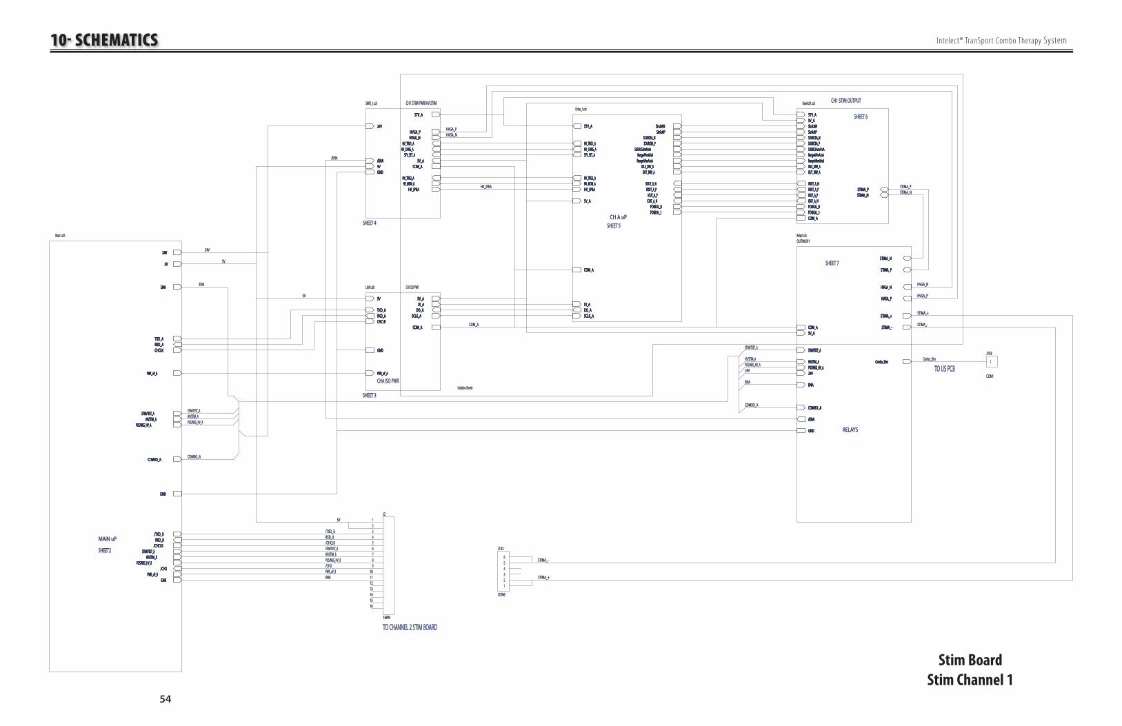
10- SCHEMATICS
54
Intelect® TranSpor t Combo Therapy System
24V24V
GNDGND
/ENA/ENACOM_ACOM_A
STV_ASTV_A
STV_SET_ASTV_SET_A
5V5V
HVGA_PHVGA_PHVGA_NHVGA_N
HV_TRG1_AHV_TRG1_AHV_CHRG_AHV_CHRG_A
5V_A5V_A
HV_TRG2_AHV_TRG2_A
HV_IPKAHV_IPKAHV_MON_AHV_MON_A
CH1 STIM PWR/HV STIMCH1 STIM PWR/HV STIMSMPS_1.schSMPS_1.sch
24V24V
GNDGND
/ENA/ENACOM_ACOM_A
STV_ASTV_A
STV_SET_ASTV_SET_A
5V5V
HVGA_PHVGA_PHVGA_NHVGA_N
HV_TRG1_AHV_TRG1_AHV_CHRG_AHV_CHRG_A
5V_A5V_A
HV_TRG2_AHV_TRG2_A
HV_IPKAHV_IPKAHV_MON_AHV_MON_A
5V5V
TXD_ATXD_A
5V_A5V_A
COM_ACOM_A
PWR_uP_APWR_uP_A
GNDGND
RXD_ARXD_ADO_ADO_A
DI_ADI_A
CHCLKCHCLKSCLK_ASCLK_A
CH1 ISO PWRCH1 ISO PWRLink1.schLink1.sch
5V5V
TXD_ATXD_A
5V_A5V_A
COM_ACOM_A
PWR_uP_APWR_uP_A
GNDGND
RXD_ARXD_ADO_ADO_A
DI_ADI_A
CHCLKCHCLKSCLK_ASCLK_A
COM_ACOM_A
DI_ADI_ADO_ADO_A
5V_A5V_A
STV_ASTV_A
STV_SET_ASTV_SET_A
IDLE_DRV_AIDLE_DRV_A
SinkAPSinkAP
SOURCEA_PSOURCEA_P
VOUT_A_NVOUT_A_N
SCLK_ASCLK_A
IOUT_A_PIOUT_A_PHV_IPKAHV_IPKA
SinkANSinkAN
OUT_DRV_AOUT_DRV_A
SOURCEA_NSOURCEA_N
IOUT_A_NIOUT_A_N
VOUT_A_PVOUT_A_P
SOURCEAmA/uASOURCEAmA/uARangeAPmA/uARangeAPmA/uA
RangeANmA/uARangeANmA/uA
HV_TRG1_AHV_TRG1_AHV_CHRG_AHV_CHRG_A
HV_MON_AHV_MON_AHV_TRG2_AHV_TRG2_A
FDBKA_0FDBKA_0FDBKA_1FDBKA_1
Drive_1.schDrive_1.sch
COM_ACOM_A
DI_ADI_ADO_ADO_A
5V_A5V_A
STV_ASTV_A
STV_SET_ASTV_SET_A
IDLE_DRV_AIDLE_DRV_A
SinkAPSinkAP
SOURCEA_PSOURCEA_P
VOUT_A_NVOUT_A_N
SCLK_ASCLK_A
IOUT_A_PIOUT_A_PHV_IPKAHV_IPKA
SinkANSinkAN
OUT_DRV_AOUT_DRV_A
SOURCEA_NSOURCEA_N
IOUT_A_NIOUT_A_N
VOUT_A_PVOUT_A_P
SOURCEAmA/uASOURCEAmA/uARangeAPmA/uARangeAPmA/uA
RangeANmA/uARangeANmA/uA
HV_TRG1_AHV_TRG1_AHV_CHRG_AHV_CHRG_A
HV_MON_AHV_MON_AHV_TRG2_AHV_TRG2_A
FDBKA_0FDBKA_0FDBKA_1FDBKA_1
STIMA_NSTIMA_NSTIMA_PSTIMA_P
COM_ACOM_A
STV_ASTV_A
VOUT_A_NVOUT_A_N
IOUT_A_PIOUT_A_P
IDLE_DRV_AIDLE_DRV_A
RangeAPmA/uARangeAPmA/uARangeANmA/uARangeANmA/uA
5V_A5V_ASinkANSinkAN
OUT_DRV_AOUT_DRV_A
SinkAPSinkAP
IOUT_A_NIOUT_A_N
VOUT_A_PVOUT_A_P
SOURCEA_NSOURCEA_NSOURCEA_PSOURCEA_PSOURCEAmA/uASOURCEAmA/uA
FDBKA_0FDBKA_0FDBKA_1FDBKA_1
Hswitch1.schHswitch1.sch
STIMA_NSTIMA_NSTIMA_PSTIMA_P
COM_ACOM_A
STV_ASTV_A
VOUT_A_NVOUT_A_N
IOUT_A_PIOUT_A_P
IDLE_DRV_AIDLE_DRV_A
RangeAPmA/uARangeAPmA/uARangeANmA/uARangeANmA/uA
5V_A5V_ASinkANSinkAN
OUT_DRV_AOUT_DRV_A
SinkAPSinkAP
IOUT_A_NIOUT_A_N
VOUT_A_PVOUT_A_P
SOURCEA_NSOURCEA_NSOURCEA_PSOURCEA_PSOURCEAmA/uASOURCEAmA/uA
FDBKA_0FDBKA_0FDBKA_1FDBKA_1
5V5V
ENAENA
TXD_ATXD_ARXD_ARXD_ACHCLKCHCLK
GNDGND
24V24V
PWR_uP_APWR_uP_A
ENBENB
/TXD_B/TXD_BRXD_BRXD_B
STIM/TEST_BSTIM/TEST_B
STIM/TEST_ASTIM/TEST_A
HV/STIM_BHV/STIM_B
HV/STIM_AHV/STIM_APOS/NEG_HV_APOS/NEG_HV_A
POS/NEG_HV_BPOS/NEG_HV_B
COMBO_ACOMBO_A
/CH2/CH2PWR_uP_BPWR_uP_B
/CHCLK/CHCLK
Main1.schMain1.sch
5V5V
ENAENA
TXD_ATXD_ARXD_ARXD_ACHCLKCHCLK
GNDGND
24V24V
PWR_uP_APWR_uP_A
ENBENB
/TXD_B/TXD_BRXD_BRXD_B
STIM/TEST_BSTIM/TEST_B
STIM/TEST_ASTIM/TEST_A
HV/STIM_BHV/STIM_B
HV/STIM_AHV/STIM_APOS/NEG_HV_APOS/NEG_HV_A
POS/NEG_HV_BPOS/NEG_HV_B
COMBO_ACOMBO_A
/CH2/CH2PWR_uP_BPWR_uP_B
/CHCLK/CHCLK
STIM/TEST_ASTIM/TEST_A
HV_IPKAHV_IPKA
STIM/TEST_ASTIM/TEST_A
HV/STIM_AHV/STIM_A
HV/STIM_BHV/STIM_B
HV/STIM_AHV/STIM_A
STIMA_NSTIMA_N
STIMA_PSTIMA_P
HV/STIM_AHV/STIM_A
24V24V
COM_ACOM_A
STIM/TEST_ASTIM/TEST_A
POS/NEG_HV_APOS/NEG_HV_A
HVGA_NHVGA_N
HVGA_PHVGA_P
COMBO_ACOMBO_A
GNDGND
5V_A5V_A
Combo_StimCombo_Stim
/ENA/ENA
ENAENA
STIMA_+STIMA_+
STIMA_-STIMA_-
OUTMUX1OUTMUX1Relay1.schRelay1.sch
STIMA_NSTIMA_N
STIMA_PSTIMA_P
HV/STIM_AHV/STIM_A
24V24V
COM_ACOM_A
STIM/TEST_ASTIM/TEST_A
POS/NEG_HV_APOS/NEG_HV_A
HVGA_NHVGA_N
HVGA_PHVGA_P
COMBO_ACOMBO_A
GNDGND
5V_A5V_A
Combo_StimCombo_Stim
/ENA/ENA
ENAENA
STIMA_+STIMA_+
STIMA_-STIMA_-
HVGA_NHVGA_N
HVGA_PHVGA_P
POS/NEG_HV_APOS/NEG_HV_A
HVGA_PHVGA_PHVGA_NHVGA_N
24V24V
SHEET2SHEET2
SHEET 4SHEET 4
POS/NEG_HV_APOS/NEG_HV_A
SHEET 5SHEET 5
POS/NEG_HV_BPOS/NEG_HV_B
SHEET 7SHEET 7
SHEET 6SHEET 6
STIM/TEST_BSTIM/TEST_B
SHEET 3SHEET 3
MAIN uPMAIN uP
CHA ISO PWRCHA ISO PWR
CH A uPCH A uP
CH1 STIM OUTPUTCH1 STIM OUTPUT
RELAYSRELAYS
Isolation BarrierIsolation Barrier
COMBO_ACOMBO_A
STIMA_NSTIMA_NSTIMA_PSTIMA_P
24V24V
COM_ACOM_A
COMBO_ACOMBO_A
Combo_StimCombo_Stim
/CH2/CH2
ENAENA
TO CHANNEL 2 STIM BOARDTO CHANNEL 2 STIM BOARD
PWR_uP_BPWR_uP_BENBENB
5V5V
5V5V
5V5V
/CHCLK/CHCLK
/TXD_B/TXD_BRXD_BRXD_B
ENAENA
/ENA/ENA
TO US PCBTO US PCB1
J103J103
CON1CON1
123456789
1010111112121313141415151616
J2J2
16PIN16PIN
123456
J102J102
CON6CON6
STIMA_+STIMA_+
STIMA_+STIMA_+
STIMA_-STIMA_-
STIMA_-STIMA_-
Stim Board
Stim Channel 1

10- SCHEMATICS
55
Intelect® TranSpor t Combo Therapy System
Stim Board- Channel A uP
5V_A5V_A5V_A5V_A1
C120C120
0.1uF0.1uF
1
C121C121
0.1uF0.1uF
1
C122C122
0.1uF0.1uF
1
C123C123
0.1uF0.1uF
1
C124C124
0.1uF0.1uF
R143R143
511K 1%511K 1%
R145R145
1K 1%1K 1%
R142R142 2.0K 1%2.0K 1%
Y100Y100
20MHz20MHz
1
C127C127
27pF27pF
1
C128C128
27pF27pF
12
DS100DS100
LED_GLED_G
12
DS101DS101
LED_YLED_Y
RES0
nRE
S0n
100
100
RESnRESn1
XTALXTAL2
EXTALEXTAL3
VCCVCC4
MD1MD15
MD0MD06
NMINMI7
STBYnSTBYn8
VCCVCC9
PA7/A23PA7/A231010
PA6/A22PA6/A221111
P52/SCK0P52/SCK01212
P51/RXD0P51/RXD01313
P50/TXD0P50/TXD01414
GNDGND1515
P97/WAITnP97/WAITn1616
P96/SYS_CLKP96/SYS_CLK1717
P95/ASnP95/ASn1818
P94/HWRnP94/HWRn1919
PA5/A21PA5/A212020
PA4/A20PA4/A202121
P93/RDnP93/RDn2222
P92/IRQ0nP92/IRQ0n2323
P91/IRQ1nP91/IRQ1n2424
P90/LWRnP90/LWRn2525
P60/CI
N0P60
/CIN0
2626
P61/CI
N1P61
/CIN1
2727
P62/CI
N2P62
/CIN2
2828
P63/CI
N3P63
/CIN3
2929
PA3/
A19
PA3/
A19
3030
PA2/CI
N10
PA2/CI
N10
3131
P64/CI
N4P64
/CIN4
3232
P65/CI
N5P65
/CIN5
3333
P66/CI
N6P66
/CIN6
3434
P67/CI
N7P67
/CIN7
3535
AVref
AVref
3636
AVCC
AVCC
3737
P70/
AN0
P70/
AN0
3838
P71/
AN1
P71/
AN1
3939
P72/
AN2
P72/
AN2
4040
P73/
AN3
P73/
AN3
4141
P74/
AN4
P74/
AN4
4242
P75/
AN5
P75/
AN5
4343
P76/
AN6
P76/
AN6
4444
P77/
AN7
P77/
AN7
4545
AVSS
AVSS
4646
PA1/
A17
PA1/
A17
4747
PA0/
A16
PA0/
A16
4848
P40/TX
D2(ir)
P40/TX
D2(ir)
4949
P41/RX
D2(ir)
P41/RX
D2(ir)
5050
P42/SCK2P42/SCK25151
P43P435252
P44P445353
P45P455454
P46/PWX0P46/PWX05555
P47/PWX1P47/PWX15656
PB7/D7PB7/D75757
PB6/D6PB6/D65858
VCCVCC5959
P27/A15P27/A156060
P26/A14P26/A146161
P25/A13P25/A136262
P24/A12P24/A126363
P23/A11P23/A116464
P22/A10P22/A106565
P21/A9P21/A96666
P20/A8P20/A86767
PB5/D5PB5/D56868
PB4/D4PB4/D46969
VSSVSS7070
VSSVSS7171
P17/A7P17/A77272
P16/A6P16/A67373
P15/A5P15/A57474
P14/A4P14/A47575
P13/
A3P1
3/A3
7676P1
2/A2
P12/
A27777
P11/
A1P1
1/A1
7878P1
0/A0
P10/
A07979
PB3/
D3PB
3/D3
8080PB
2/D2
PB2/
D28181
P30/
D8P3
0/D8
8282P3
1/D9
P31/
D98383
P32/
D10
P32/
D10
8484P3
3/D1
1P3
3/D1
18585
P34/
D12
P34/
D12
8686P3
5/D1
3P3
5/D1
38787
P36/
D14
P36/
D14
8888P3
7/D1
5P3
7/D1
58989
PB1/
D1PB
1/D1
9090PB
0/D0
PB0/
D09191
VSS
VSS
9292P8
0P8
09393
P81
P81
9494P8
2P8
29595
P83
P83
9696P84
/TXD1
/..P84
/TXD1
/..9797
P85/RX
D1/..
P85/RX
D1/..
9898P86
/SCK1/
..P86
/SCK1/
..9999
U104U104
H8S2144H8S2144
1
23
U102U102
MCP120MCP120
3
21
84
U106AU106A
TLC2272ACDTLC2272ACD
5
67
U106BU106B
TLC2272ACDTLC2272ACD
need 512K +/- 0.25%maxneed 512K +/- 0.25%max
0.25% or better ideally 0.25% or better ideally
use 4.75V trip pointuse 4.75V trip point
18
27
36
45
R130R13010K_QUAD10K_QUAD
18
27
36
45
R129R12910K_QUAD10K_QUAD
12
DS102DS102
LED_YLED_Y
18
27
36
45
R127R1272K2_QUAD2K2_QUAD
GREENGREEN YELLOWYELLOW YELLOWYELLOW
1
C131C1310.1uF0.1uF
1
2
3
D110D110
BAV99BAV99
1
C132C132.01uF.01uF
1
2
3
D111D111
BAV99BAV99
HV_IP
KAHV
_IPKA
VOUT
_A_N
VOUT
_A_N
VOUT
_A_P
VOUT
_A_P
IOUT_A
_PIOU
T_A_P
IOUT_A
_NIOU
T_A_N
STV_SET_ASTV_SET_AIDLE_DRV_AIDLE_DRV_A
SCLK
_ASC
LK_A Ran
geANm
A/uA
RangeA
NmA/u
ARan
geAPm
A/uA
RangeA
PmA/u
A
SOUR
CEAmA
/uASO
URCEA
mA/uA
5V_A
5V_A
5V_A5V_A
HV_TR
G1_A
HV_TR
G1_A
HV_CH
RG_A
HV_CH
RG_A
HV_TRG2_AHV_TRG2_A
1
C119C119
0.1uF0.1uF
1
C118C118
0.1uF0.1uF
R135R13527.4K 1%27.4K 1%
R141R14110K 1%10K 1%
505V in = 5V out505V in = 5V out
R128R128
1K 1%1K 1%
C125C1250.01uF0.01uF
C126C126
0.01uF0.01uF
C129C129
1uF1uF
COM_ACOM_A
5V_A5V_A
COM_ACOM_A
COM_ACOM_A
COM_ACOM_A
5V_A5V_A
R133R133
1M 1%1M 1%
R134R134
1M 1%1M 1%
R139R1391M 1%1M 1%
R140R1401M 1%1M 1%
5V_A5V_A
COM_ACOM_A
COM_ACOM_A
COM_ACOM_A
COM_ACOM_A
COM_ACOM_A
5V_A5V_A
COM_ACOM_A
Programming HeaderProgramming Header5V_A5V_A
OUT_DRV_AOUT_DRV_A
IDLE_DRV_AIDLE_DRV_A
HV_MON_AHV_MON_A
STV_ASTV_A
DO_ADO_ADO_ADO_A
DI_ADI_ADI_ADI_A
R138R1381M 1%1M 1%
R137R1371M 1%1M 1%
R136R1361M 1%1M 1%
COM_ACOM_A
5V_A5V_A
5V_A5V_A
COM_ACOM_A
HV_TRG1_AHV_TRG1_A
HV_CHRG_AHV_CHRG_A
STV_SET_ASTV_SET_A
HV_TRG2_AHV_TRG2_A
HV_IPKAHV_IPKA
RESET_A RESET_A
HV_MON_AHV_MON_A
SCLK_ASCLK_ASCLK_ASCLK_A
STV_ASTV_A
IOUT_BIOUT_BVOUT_BVOUT_B
HIHI
HIHI
LOWLOW
LOWLOW
SOURCEAmA/uASOURCEAmA/uA
FDBKA_0FDBKA_0FDBKA_1FDBKA_1
VCL_AVCL_ACOM_ACOM_A
COM_ACOM_A
SinkAPSinkAP
SinkANSinkAN
SOURCEA_NSOURCEA_N
SOURCEA_PSOURCEA_P
RangeANmA/uARangeANmA/uA
RangeAPmA/uARangeAPmA/uA
PWMPWMPWMPWM
E_A_
RAW
E_A_
RAW
E_A_
AVG
E_A_
AVG
VOUT_A_NVOUT_A_NVOUT_A_PVOUT_A_PIOUT_A_NIOUT_A_NIOUT_A_PIOUT_A_P
P90,91,92 MUST BE PULLED UP TO PROGRAM CHIPP90,91,92 MUST BE PULLED UP TO PROGRAM CHIP
1
2 3
U105AU105A
74HC12574HC125
1313
1212 1111
U105DU105D
74HC12574HC125
1010
9 8
U105CU105C
74HC12574HC125
4
5 6
14147
U105BU105B
74HC12574HC125COM_ACOM_A
COM_ACOM_A
12345
J100J100
CON5CON5
1
C162C162
0.1uF0.1uF

10- SCHEMATICS
56
Intelect® TranSpor t Combo Therapy System
Stim Board- Channel A
Stim Output
1
23
Q117Q117BSP299BSP299
1
23
Q118Q118BSP319BSP319
1
23
Q111Q111
BSP255BSP255
1
23
Q122Q122BSP255BSP255
R174R1742.2R 1%2.2R 1%
1
23
Q128Q128
BSP299BSP299
R192R192100K 1%100K 1%R163R163
100K 1%100K 1%
12
3
Q129Q129
BSP319BSP319
R203R2032.2R 1%2.2R 1%
R187R187
665 1%665 1%
R188R188
10R 1W 1%10R 1W 1%
R178R178
2.0K 1%2.0K 1%
R173R1732.0K 1%2.0K 1%
R202R2022.0K 1%2.0K 1%
5
67
U112BU112B
TLC2274ACDTLC2274ACD5
67
U110BU110B
TLC2272ACDTLC2272ACD
3
21
84
U110AU110A
TLC2272ACDTLC2272ACD
1010
98
U112CU112C
TLC2274ACDTLC2274ACD
R197R197
1M 1%1M 1%
R167R167
27.4K 1%27.4K 1%
R170R17027.4K 1%27.4K 1%
R168R168
1M 1%1M 1%
R196R196
27.4K 1%27.4K 1%
1
C139C139
0.01uF0.01uF R222R222
27.4K 1%27.4K 1%R221R2216.81K 1%6.81K 1%
R227R2276.81K 1%6.81K 1%
R228R228
27.4K 1%27.4K 1%
R181R181
10K 1%10K 1%
R182R18210K 1%10K 1%
R220R220
10K 1%10K 1%
R171R1716.81K 1%6.81K 1%
R185R185
6.81K 1%6.81K 1%
1
C141C141
0.01uF0.01uF
R158R158
665 1%665 1%
R159R159
10R 1W 1%10R 1W 1%
R155R155
6.81K 1%6.81K 1%
1
C134C134
.01uF.01uF
1010
98
U111CU111C
TLC2274ACDTLC2274ACD
5
67
U111BU111B
TLC2274ACDTLC2274ACD
R191R191100K 1%100K 1%R162R162
100K 1%100K 1%
1C145C145
100pF100pF
1C138C138
100pF100pF
1
23
Q120Q120
BSP255BSP255
1
23
Q109Q109BSP255BSP255
1
3ncnc
2
D119D119BZX84C10BZX84C10
1
3
ncnc2
D120D120
BZX84C10BZX84C10
1
3
ncnc2
D118D118
BZX84C10BZX84C10
1
C140C140
27pF27pF
1
2
Q107Q107
FMMTA42FMMTA42
R175R175200 1%200 1% R204R204
200 1%200 1%
R179R179
2.0K 1%2.0K 1%
R201R201
27.4R 1%27.4R 1%
A0A01
N01N012
GND
GND
3
N03N034
ENEN5
V+V+6
N04N047
COMCOM8
N02N029
A1A11010
U109U109
MAX4634MAX4634
R177R1771.0K 1%1.0K 1% R194R194
10K 1%10K 1%
R193R1931.07K 1%1.07K 1%R165R165
10K 1%10K 1%
R164R1641.07K 1%1.07K 1%
R190R190
10K 1%10K 1%
R161R161
10K 1%10K 1%
R152R152
100K 1%100K 1%
3
21
41111
U111AU111A
TLC2274ACDTLC2274ACD
R205R20510K 1%10K 1%
C149C149
1uF/10V1uF/10V
R208R2081M 1%1M 1%
R207R207
10K 1%10K 1%
1212
13131414
U111DU111D
TLC2274ACDTLC2274ACD C152C152
1uF/10V1uF/10V
R214R2141M 1%1M 1%
R213R213
10K 1%10K 1%
R211R211
10K 1%10K 1%
3
21
41111
U112AU112A
TLC2274ACDTLC2274ACDC155C155
1uF/10V1uF/10V
R219R219
1M 1%1M 1%
R226R226
10K 1%10K 1%
1212
13131414
U112DU112D
TLC2274ACDTLC2274ACD
C158C158
1uF/10V1uF/10V
R225R2251M 1%1M 1%
R217R217
10K 1%10K 1%
R223R223
10K 1%10K 1%
R215R21510K 1%10K 1%
R216R216
27.4K 1%27.4K 1%
R210R210
27.4K 1%27.4K 1%R209R20910K 1%10K 1%
C153C153100pf100pf
C156C156100pf100pf
Q127Q127
2N70022N7002
R195R195
1K 1%1K 1%
R198R198
2K 1%2K 1%
1
23
Q126Q126BSP299BSP299
Q116Q116
2N70022N7002
R166R166
1K 1%1K 1%
R169R169
2K 1%2K 1%
1
2 3
Q115Q115BSP299BSP299
C137C137
100pF100pF
C144C144
100pF100pF
R206R206
10K 1%10K 1%
C147C147100pF100pF
R212R212
10K 1%10K 1%
C150C150
100pF100pF
R218R218
10K 1%10K 1%
R224R224
10K 1%10K 1%
R153R153200K 1%200K 1%
C142C142
22pF/200V22pF/200V
C143C143
22pF/200V22pF/200V
C135C13522pF/200V22pF/200V
C136C13622pF/200V22pF/200V
C154C15410pF10pF
Q119Q119
FMMT4403FMMT4403
R154R1544R7 1W 5%4R7 1W 5%
R184R1846.81K 1%6.81K 1%
R183R1834R7 1W 5%4R7 1W 5%
R186R1863.30K 1%3.30K 1%
R157R157
3.30K 1%3.30K 1%
R160R160
27.4R 1%27.4R 1%
COM_ACOM_A
R189R189
27.4R 1%27.4R 1%
R180R180
27.4K 1%27.4K 1%
COM_ACOM_A
COM_ACOM_A
5V_A5V_A
R176R1761.0K 1%1.0K 1%
COM_ACOM_A
5V_A5V_A
COM_ACOM_A
R172R172
27.4R 1%27.4R 1%
COM_ACOM_ACOM_ACOM_ACOM_ACOM_A
5V_A5V_A
COM_ACOM_A
COM_ACOM_A
COM_ACOM_A
COM_ACOM_A
COM_ACOM_ACOM_ACOM_A
Q121BQ121BBC807UBC807U
Q121AQ121A
BC807UBC807U
Q108Q108
FMMT4403FMMT4403
R156R1566.81K 1%6.81K 1%
Q110BQ110BBC807UBC807U
Q110AQ110A
BC807UBC807U
COM_ACOM_ACOM_ACOM_A
COM_ACOM_A
STIMA_PSTIMA_PSTIMA_NSTIMA_N
IDLE_DRV_AIDLE_DRV_A
OUT_DRV_AOUT_DRV_A
STV_ASTV_A
SinkANSinkAN
RangeANmA/uARangeANmA/uA RangeAPmA/uARangeAPmA/uA
SinkAPSinkAP
VOUT_A_NVOUT_A_N
VOUT_A_PVOUT_A_P
IOUT_A_NIOUT_A_N
IOUT_A_PIOUT_A_P
FDBKA_1FDBKA_1FDBKA_0FDBKA_0
R151R151
27.4K 1%27.4K 1%SOURCEAmA/uASOURCEAmA/uA
5V_A5V_A5V_A5V_A
COM_ACOM_A
5V_A5V_A
COM_ACOM_A
SOURCEA_NSOURCEA_NSOURCEA_PSOURCEA_P
COM_ACOM_A
5V_A5V_A
C157C15710pF10pF
C151C15110pF10pF
C148C14810pF10pF
COM_ACOM_A
COM_ACOM_A
COM_ACOM_A
1
2
Q113Q113
FMMTA42FMMTA421
2
Q114Q114
FMMTA42FMMTA42
1
2
Q124Q124FMMTA42FMMTA42
1
2
Q125Q125FMMTA42FMMTA42
1 2
3
D121D121BAV99BAV99
1 2
3
D122D122BAV99BAV99
1 2
3
D123D123BAV99BAV99
1 2
3
D124D124BAV99BAV99
16
D112AD112ACMXD2004CMXD2004
25
D112BD112BCMXD2004CMXD2004
34
D112CD112CCMXD2004CMXD2004
16
D115AD115ACMXD2004CMXD2004
25
D115BD115BCMXD2004CMXD2004
34
D115CD115CCMXD2004CMXD2004
R230R230
100R 0.25W100R 0.25W
C159C15947pF47pF
C160C160
1000pF 250VAC1000pF 250VAC
STIMA_NSTIMA_N
STIMA_NSTIMA_N
STIMA_PSTIMA_P
STIMA_PSTIMA_P
4
31
52
U108U108
OPA364OPA364
Q112Q112
FZT657CTFZT657CT
Q123Q123FZT657CTFZT657CT

10- SCHEMATICS
57
Intelect® TranSpor t Combo Therapy System
Stim Board- Channel A
ISO Power
5V5V
TXD_ATXD_A
5V_A5V_A
COM_ACOM_APWR_uP_APWR_uP_A
GNDGND
RXD_ARXD_A
DI_ADI_A
DO_ADO_ACHCLKCHCLK SCLK_ASCLK_A
a1a11
k1k12
k2k23
a2a24
VccVcc8
O1O17
O2O26
GNDGND5
U9U9
OPTO_HPCL2630OPTO_HPCL2630
a1a11
k1k12
k2k23
a2a24
VccVcc8
O1O17
O2O26
GNDGND5
U10U10
OPTO_HPCL2630OPTO_HPCL2630
5V_A5V_A
COM_ACOM_A
COM_ACOM_A
5V_A5V_A
5V5V
5V in 5V out @ 1W converter (DIP)5V in 5V out @ 1W converter (DIP)
1
23
Q3Q3BSP319BSP319
1KHz Clock for timing1KHz Clock for timing
Serial Data to chanSerial Data to chan1
2
R25R2510K 1%10K 1%
R102R10210K 1%10K 1%
R101R10110K 1%10K 1%
COM_ACOM_A
R103R103470R 1%470R 1%
R27R27470R 1%470R 1%
R28R28470R 1%470R 1%
Q2Q2
2N70022N7002
Q1Q1
2N70022N7002
11
22
FB100FB100
120120
Q100Q100
2N70022N7002
GNDGND
R29R2910K 1%10K 1%
+ IN+ IN1414
-IN-IN1
+OUT+OUT8
-OUT-OUT1010
COMCOM9
NCNC7
PS1PS1 26D-05S05N26D-05S05N
GNDGND
C100C1001uF/10V1uF/10V
C21C211uF/10V1uF/10V
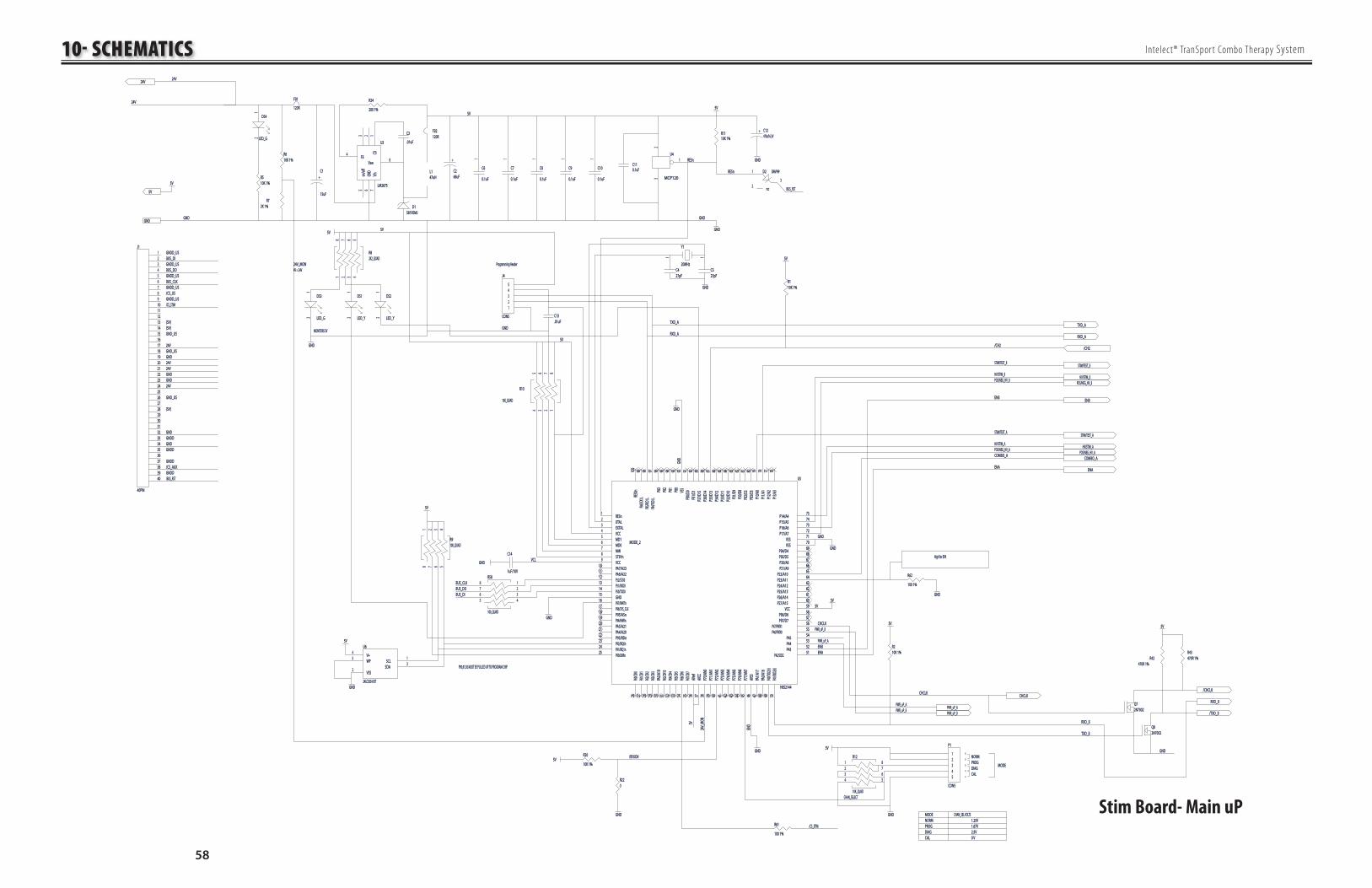
10- SCHEMATICS
58
Intelect® TranSpor t Combo Therapy System
Stim Board- Main uP
Y1Y1
20MHz20MHz
1
C4C427pF27pF
1
C5C527pF27pF
12
DS4DS4
LED_GLED_G
24V_MON24V_MON
24V_
MON
24V_
MON
CHCLKCHCLK
ENAENA
PWR_uP_APWR_uP_A
CHCLKCHCLK
ENBENB
5V5V
1
C6C6
0.1uF0.1uF
1
C7C7
0.1uF0.1uF
1
C8C8
0.1uF0.1uF
1
C9C9
0.1uF0.1uF
5V5V
RESnRESn
GND
GND
GNDGND
12
DS3DS3
LED_GLED_G
12
DS1DS1
LED_YLED_Y
12
DS2DS2
LED_YLED_Y
5V5V
GNDGNDMONITORS 5VMONITORS 5V
4V = 24V4V = 24V
1
C10C10
0.1uF0.1uF
RES0
nRE
S0n
100
100
RESnRESn1
XTALXTAL2
EXTALEXTAL3
VCCVCC4
MD1MD15
MD0MD06
NMINMI7
STBYnSTBYn8
VCCVCC9
PA7/A23PA7/A231010
PA6/A22PA6/A221111
P52/SCK0P52/SCK01212
P51/RXD0P51/RXD01313
P50/TXD0P50/TXD01414
GNDGND1515
P97/WAITnP97/WAITn1616
P96/SYS_CLKP96/SYS_CLK1717
P95/ASnP95/ASn1818
P94/HWRnP94/HWRn1919
PA5/A21PA5/A212020
PA4/A20PA4/A202121
P93/RDnP93/RDn2222
P92/IRQ0nP92/IRQ0n2323
P91/IRQ1nP91/IRQ1n2424
P90/LWRnP90/LWRn2525
P60/CI
N0P60
/CIN0
2626
P61/CI
N1P61
/CIN1
2727
P62/CI
N2P62
/CIN2
2828
P63/CI
N3P63
/CIN3
2929
PA3/
A19
PA3/
A19
3030
PA2/CI
N10
PA2/CI
N10
3131
P64/CI
N4P64
/CIN4
3232
P65/CI
N5P65
/CIN5
3333
P66/CI
N6P66
/CIN6
3434
P67/CI
N7P67
/CIN7
3535
AVref
AVref
3636
AVCC
AVCC
3737
P70/
AN0
P70/
AN0
3838
P71/
AN1
P71/
AN1
3939
P72/
AN2
P72/
AN2
4040
P73/
AN3
P73/
AN3
4141
P74/
AN4
P74/
AN4
4242
P75/
AN5
P75/
AN5
4343
P76/
AN6
P76/
AN6
4444
P77/
AN7
P77/
AN7
4545
AVSS
AVSS
4646
PA1/
A17
PA1/
A17
4747
PA0/
A16
PA0/
A16
4848
P40/TX
D2(ir)
P40/TX
D2(ir)
4949
P41/RX
D2(ir)
P41/RX
D2(ir)
5050
P42/SCK2P42/SCK25151
P43P435252
P44P445353
P45P455454
P46/PWX0P46/PWX05555
P47/PWX1P47/PWX15656
PB7/D7PB7/D75757
PB6/D6PB6/D65858
VCCVCC5959
P27/A15P27/A156060
P26/A14P26/A146161
P25/A13P25/A136262
P24/A12P24/A126363
P23/A11P23/A116464
P22/A10P22/A106565
P21/A9P21/A96666
P20/A8P20/A86767
PB5/D5PB5/D56868
PB4/D4PB4/D46969
VSSVSS7070
VSSVSS7171
P17/A7P17/A77272
P16/A6P16/A67373
P15/A5P15/A57474
P14/A4P14/A47575
P13/
A3P1
3/A3
7676P1
2/A2
P12/
A27777
P11/
A1P1
1/A1
7878P1
0/A0
P10/
A07979
PB3/
D3PB
3/D3
8080PB
2/D2
PB2/
D28181
P30/
D8P3
0/D8
8282P3
1/D9
P31/
D98383
P32/
D10
P32/
D10
8484P3
3/D1
1P3
3/D1
18585
P34/
D12
P34/
D12
8686P3
5/D1
3P3
5/D1
38787
P36/
D14
P36/
D14
8888P3
7/D1
5P3
7/D1
58989
PB1/
D1PB
1/D1
9090PB
0/D0
PB0/
D09191
VSS
VSS
9292P8
0P8
09393
P81
P81
9494P8
2P8
29595
P83
P83
9696P84
/TXD1
/..P84
/TXD1
/..9797
P85/RX
D1/..
P85/RX
D1/..
9898P86
/SCK1/
..P86
/SCK1/
..9999
U5U5
H8S2144H8S2144
GND
GND
5V5V
1
23
U4U4
MCP120MCP120
GNDGND
RESnRESn
18
27
36
45
R10R10
10K_QUAD10K_QUAD
18
27
36
45
R9R910K_QUAD10K_QUAD
18
27
36
45
R8R82K2_QUAD2K2_QUAD
1
3
ncnc2
D2D2 BAV99BAV99
CHAN_SELECTCHAN_SELECT
1 82 73 64 5
R12R12
10K_QUAD10K_QUAD
CBCB123
FBFB4
on/o
ffon
/off
5
GND
GND
6
VinVin7
VswVsw8
U3U3
LM2675LM2675
+
C1C1
15uF15uF
C3C3
.01uF.01uF
L1L147uH47uH
+
C2C268uF68uF
D1D15819SMJ5819SMJ
FB1FB1
120R120R
FB2FB2120R120R
R11R1110K 1%10K 1%
C11C110.1uF0.1uF
C13C13.01uF.01uF
C14C14
1uF/10V1uF/10V
5V5V
GNDGND
GNDGND
GNDGND
5V5V
GNDGND
GNDGND
5V5V
GNDGND
5V5V
GNDGND
RXD_ARXD_A
TXD_ATXD_A
GNDGND
5V5V
ENAENA
ENBENB
24V24V
5V5V
5V5VR5R510K 1%10K 1%
R6R610K 1%10K 1%
R7R72K 1%2K 1%
ENBENB
GNDGND
1234567891010111112121313141415151616171718181919202021212222232324242525262627272828292930303131323233333434353536363737383839394040
J1J1
40PIN40PIN
GNDD_USGNDD_US
GNDD_USGNDD_US
GNDD_USGNDD_US
GNDD_USGNDD_US
GNDD_USGNDD_US
GNDDGNDD
GNDDGNDD
GNDDGNDD
BUS_DIBUS_DI
BUS_DOBUS_DO
BUS_CLKBUS_CLK
/CS_US/CS_US
/CS_AUX/CS_AUX
/BUS_RST/BUS_RSTGNDDGNDD
GNDGND
GNDGND
GNDGND
GNDGND
GNDGND
GND_USGND_US
GND_USGND_US
GND_USGND_US
(5V)(5V)
(5V)(5V)(5V)(5V)
/CS_STIM/CS_STIM
24V24V
24V24V24V24V
24V24V
PROGPROGDIAGDIAGCALCAL
NORMNORM
24V24V
MODEMODE
/CS_STIM/CS_STIM
BUS_CLKBUS_CLKBUS_DOBUS_DOBUS_DIBUS_DI
/BUS_RST/BUS_RST
Programming HeaderProgramming Header
GNDGND
STIM/TEST_BSTIM/TEST_B
HV/STIM_BHV/STIM_BPOS/NEG_HV_BPOS/NEG_HV_B
CHCLKCHCLK
MODEMODENORMNORMPROGPROGDIAGDIAGCALCAL
CHAN_SEL VOLTSCHAN_SEL VOLTS1.25V1.25V1.67V1.67V2.5V2.5V0 V0 V
TXD_ATXD_A
RXD_ARXD_A
/TXD_B/TXD_B
RXD_BRXD_BPWR_uP_APWR_uP_A
MODE_2MODE_2
STIM/TEST_ASTIM/TEST_A
HV/STIM_AHV/STIM_APOS/NEG_HV_APOS/NEG_HV_A
STIM/TEST_BSTIM/TEST_B
HV/STIM_BHV/STIM_BPOS/NEG_HV_BPOS/NEG_HV_B
COMBO_ACOMBO_A
RXD_BRXD_B
TXD_BTXD_B
PWR_uP_APWR_uP_A
GNDGND
VCLVCL
/CH2/CH2/CH2/CH2
5V5V
P90,91,92 MUST BE PULLED UP TO PROGRAM CHIPP90,91,92 MUST BE PULLED UP TO PROGRAM CHIP
24V24V
R20R20
10K 1%10K 1%
R22R220
GNDGND
5V5VREVISIONREVISION
GNDGND
R61R61
100 1%100 1%
5V5V
R24R24
200 1%200 1%
PWR_uP_BPWR_uP_BPWR_uP_BPWR_uP_B
PWR_uP_BPWR_uP_B
+ C12C12470uf 6.3V470uf 6.3V
GNDGND
STIM/TEST_ASTIM/TEST_A
HV/STIM_AHV/STIM_APOS/NEG_HV_APOS/NEG_HV_A
COMBO_ACOMBO_A
ENAENA
R1R110K 1%10K 1%
5V5V
/CHCLK/CHCLK
R42R42470R 1%470R 1%
R43R43470R 1%470R 1%
GNDGND
Q7Q72N70022N7002
Q8Q82N70022N7002
5V5V
R2R210K 1%10K 1%
5V5V
R62R62
100 1%100 1%
GNDGND
18273645
R58R58
100_QUAD100_QUAD
V+V+4
SCLSCL1
SDASDA3
WPWP5
VSSVSS2
U6U6
24LC02B-I/OT24LC02B-I/OT
12345
P1P1
CON5CON5
12345
J4J4
CON5CON5
High for EPRHigh for EPR

10- SCHEMATICS
59
Intelect® TranSpor t Combo Therapy System
Stim Board- Channel A
Relays
STIMA_NSTIMA_N
STIMA_PSTIMA_P
R100R1001K 5W axial1K 5W axial
24V24V
STIM/TEST_ASTIM/TEST_A
24V24V
POS/NEG_HV_APOS/NEG_HV_A
HVGA_NHVGA_N
HVGA_PHVGA_P
32
4
67
51
8
K3K3
DPDT - 24VDPDT - 24V
32
4
67
51
8
K2K2
DPDT - 24VDPDT - 24V
32
4
67
51
8
K1K1
DPDT - 24VDPDT - 24V
TestLoad/PatientTestLoad/Patient
1 2 3 4
5678
HV+/HV-HV+/HV-
STIM/HVSTIM/HV
24V24V
24V24V
24V24V
CH1_Out_+CH1_Out_+
CH1_Out_-CH1_Out_-
L103L103
INDUCTOR2INDUCTOR2L104L104
INDUCTOR2INDUCTOR21234
J101J101
CON4CON4
PLASTICS ONEPLASTICS ONE
38319 JACK38319 JACK3
2
4
1
VIEW FROM FRONTVIEW FROM FRONT
GNDGND
IN 1IN 11
IN 2IN 22
IN 3IN 33
IN 4IN 44
IN 5IN 55
IN 6IN 66
IN 7IN 77
COMMONCOMMON8
CLAMPCLAMP9
OUT 7OUT 71010
OUT 6OUT 61111
OUT 5OUT 51212
OUT 4OUT 41313
OUT 3OUT 31414
OUT 2OUT 21515
OUT 1OUT 11616
U7U7
ULN2003L(16)ULN2003L(16)
24V24V
/ENA/ENA
HV/STIM_AHV/STIM_A
ENAENA
STIM/TEST_ASTIM/TEST_A
HV/STIM_AHV/STIM_APOS/NEG_HV_APOS/NEG_HV_ACOMBO_ACOMBO_A
ENAENA
NEG/POS_HV_ANEG/POS_HV_A
TEST/STIM_ATEST/STIM_A
STIM/HV_ASTIM/HV_A
COMBO_ACOMBO_A
STIMA_+STIMA_+
STIMA_-STIMA_-
32
4
67
51
8
K4K4
DPDT - 24VDPDT - 24V
24V24V
/COMBO_A/COMBO_A
/COMBO_A/COMBO_A
Combo_StimCombo_Stim
GNDGNDGNDGND
TEST/STIM_A2TEST/STIM_A2
STIM/TEST_A2 STIM/TEST_A2
STIM/TEST_A2STIM/TEST_A2STIM/TEST_A2STIM/TEST_A2
C161C161
.001uF.001uFGNDGND

10- SCHEMATICS
60
Intelect® TranSpor t Combo Therapy System
Stim Board- Channel A
Stim Power and HV
CMP
CMP
1
-2
IsensIsens3
T4
VeVe5
OUTOUT6VcVc
7
VrVr8
U11U11
UCC3803DUCC3803D
1
D100D100 ES1DES1D
1
D101D101ES1DES1D
C101C101
10p/200V10p/200V
C102C102
10p/200V10p/200V
G1
D2
S3
Q6Q6
IRFR120NIRFR120N
1
D10D10
10MQ100N10MQ100N
D9D9
2EZ62D5MSCT2EZ62D5MSCT
1
C30C30
470pF470pF 1
C31C31
100pF100pF
1
C28C28
0.1uF0.1uF
1
C29C29
0.1uF0.1uF
1
C26C26
0.1uF0.1uF
1
C32C32
0.1uF0.1uF
1
C22C22
0.1uF0.1uF
L2L2
3u3/1.1A3u3/1.1A
1
C23C23
2u2/35V2u2/35V1
C24C24
0.1uF0.1uF
C103C103
10u/100V10u/100V
C104C104
10u/100V10u/100V
C105C105
10u/100V10u/100V
C106C106
10u/100V10u/100V
F#580-650F#580-650
1
C107C107
.022uF/200V.022uF/200V
1
C108C108
.022uF/200V.022uF/200V
1
2
Q5Q5
FMMT2222ACTFMMT2222ACT
12
+ C25C256u8/35V6u8/35V
12
+C27C27
2u2/25V2u2/25V
+1
-2
C109C109
10u/100V10u/100V
C110C110
10u/100V10u/100V
C111C111
10u/100V10u/100V
C112C112
10u/100V10u/100V
L101L101
10uH/0.3A10uH/0.3A
1
D102D102
US1JUS1J
1
D106D106
US1JUS1J
12
3
Q105Q105
X0202MNX0202MN
1
D105D105US1JUS1J
1
D104D104US1JUS1J
12
3
Q106Q106
X0202MNX0202MN
C116C116
.015uF/600V.015uF/600V
C115C115
.01uF/600V.01uF/600V
R117R117
1K 1%1K 1%
Q104Q104
PHT1N60RPHT1N60R
L102L102
100 mH100 mH
D103D103US1JUS1J
50mA Ipk50mA Ipk
C113C113
0.1uF0.1uF
Q4Q4
FMMT2907ACTFMMT2907ACT R32R32
820 1/2W820 1/2W
R31R31
30K30K
R30R305.62K 1%5.62K 1%
C114C114
220pf220pf
R113R113200K 1%200K 1%
3
21
84
U101AU101A
TLC2272ACDTLC2272ACD
5
67
U101BU101B
TLC2272ACDTLC2272ACDC117C117
.01uF/50V.01uF/50V R126R1261M1M
R124R124
10K 1%10K 1%
R125R1255.11K 1%5.11K 1%
FB102FB1021K1K
FB101FB101
1K1K
32
1
R106R106
0 OHM0 OHM
Q102Q102
FZT657CTFZT657CT
Q103Q103
FZT757FZT757
R122R122
1.0K 1%1.0K 1%
R123R123
10K 1%10K 1%
R121R121
1R51R5R120R1201.1K1.1K
R119R119
1.1K1.1K
R118R118
1K 1%1K 1%
R116R116
1K 1%1K 1%
R112R112
49.9K 1%49.9K 1%
R114R114
2.2K2.2KR115R115
182R 1%182R 1%
5V_A5V_A
5V_A5V_A COM_ACOM_A
GNDGND
5V5V
R34R34
100K100K
R33R33
100K100K
R36R36
2K 1%2K 1%
R35R35
16.5K 1%16.5K 1%
R37R37
1K 1%1K 1%
R38R38
27.4R 1%27.4R 1%
R39R39
1K 1%1K 1%
R104R104
100R100R
R105R105
100R100R
R40R40
0R2 1W0R2 1W
R107R107100K 1%100K 1%
R108R108100K 1%100K 1%
R109R109
100K 1%100K 1%
R110R110
100K 1%100K 1%
R111R1116.49K 1%6.49K 1%
GNDGND
GNDGND
5V_A5V_A
0.25W0.25W
0.25W0.25W
1%1%
/ENA/ENA
24V24V
HVGA_NHVGA_N
HVGA_PHVGA_P
HV_CHRG_AHV_CHRG_A
GNDGND
COM_ACOM_A
5V_A5V_A
5V5V
STV_ASTV_A
HV_MON_AHV_MON_A
HV_TRG1_AHV_TRG1_A
HV_TRG2_AHV_TRG2_A
HV_CHRG_AHV_CHRG_A
HV_IPKAHV_IPKA
STV_SET_ASTV_SET_A
STV_ASTV_A
HV_MON_AHV_MON_A
HV_TRG2_AHV_TRG2_A
HV_IPKAHV_IPKA
/ENA/ENA
24V24V
STV_SET_ASTV_SET_A
HV_TRG1_AHV_TRG1_A
HVGA_NHVGA_N
HVGA_PHVGA_P
5V_A5V_A
NON-ISOLATEDNON-ISOLATED
COM_ACOM_A
1
3
6
4
U12U12
TLP181TLP181
1
2 7
8
5
6
T1T1 TRANS EPR STIMTRANS EPR STIM
5V_A5V_A
12
3
D107D107BAV99BAV99
1 2
3
D108D108BAV99BAV99
1
2
Q101Q101
FMMT2222ACTFMMT2222ACT
4
31
52
U100U100
OPA364OPA364
C60C60
470pF 200V470pF 200V
R65R65220220
R64R64220220

10- SCHEMATICS
61
Intelect® TranSpor t Combo Therapy System
Stim Board- Channel 2
24V24V
GNDGND
/ENB/ENB
COM_BCOM_B
STV_BSTV_B
STV_SET_BSTV_SET_B
5V5V
HVGB_NHVGB_NHVGB_PHVGB_P
HV_TRG1_BHV_TRG1_B
HV_CHRG_BHV_CHRG_B
5V_B5V_B
HV_TRG2_BHV_TRG2_B
HV_IPKBHV_IPKBHV_MON_BHV_MON_B
CH2 STIM PWR/HV STIMCH2 STIM PWR/HV STIMSMPS_2.schSMPS_2.sch
24V24V
GNDGND
/ENB/ENB
COM_BCOM_B
STV_BSTV_B
STV_SET_BSTV_SET_B
5V5V
HVGB_NHVGB_NHVGB_PHVGB_P
HV_TRG1_BHV_TRG1_B
HV_CHRG_BHV_CHRG_B
5V_B5V_B
HV_TRG2_BHV_TRG2_B
HV_IPKBHV_IPKBHV_MON_BHV_MON_B
5V5V
/TXD_B/TXD_B
5V_B5V_B
COM_BCOM_B
PWR_uP_BPWR_uP_BGNDGND
RXD_BRXD_B DI_BDI_BDO_BDO_B
/CHCLK/CHCLK SCLK_BSCLK_B
CHB ISO PWRCHB ISO PWRLink2.schLink2.sch
5V5V
/TXD_B/TXD_B
5V_B5V_B
COM_BCOM_B
PWR_uP_BPWR_uP_BGNDGND
RXD_BRXD_B DI_BDI_BDO_BDO_B
/CHCLK/CHCLK SCLK_BSCLK_B
STIMB_NSTIMB_NSTIMB_PSTIMB_P
COM_BCOM_B
STV_BSTV_B
VOUT_B_NVOUT_B_N
IOUT_B_PIOUT_B_P
IDLE_DRV_BIDLE_DRV_B
RangeBPmA/uARangeBPmA/uARangeBNmA/uARangeBNmA/uA
5V_B5V_BSinkBNSinkBN
OUT_DRV_BOUT_DRV_B
SinkBPSinkBP
IOUT_B_NIOUT_B_N
VOUT_B_PVOUT_B_P
SOURCEB_NSOURCEB_NSOURCEB_PSOURCEB_PSOURCEBmA/uASOURCEBmA/uA
FDBKB_0FDBKB_0FDBKB_1FDBKB_1
Hswitch2.schHswitch2.sch
STIMB_NSTIMB_NSTIMB_PSTIMB_P
COM_BCOM_B
STV_BSTV_B
VOUT_B_NVOUT_B_N
IOUT_B_PIOUT_B_P
IDLE_DRV_BIDLE_DRV_B
RangeBPmA/uARangeBPmA/uARangeBNmA/uARangeBNmA/uA
5V_B5V_BSinkBNSinkBN
OUT_DRV_BOUT_DRV_B
SinkBPSinkBP
IOUT_B_NIOUT_B_N
VOUT_B_PVOUT_B_P
SOURCEB_NSOURCEB_NSOURCEB_PSOURCEB_PSOURCEBmA/uASOURCEBmA/uA
FDBKB_0FDBKB_0FDBKB_1FDBKB_1
COM_BCOM_B
DI_BDI_BDO_BDO_B
5V_B5V_B
STV_BSTV_B
STV_SET_BSTV_SET_B
IDLE_DRV_BIDLE_DRV_B
SinkBPSinkBP
SOURCEB_PSOURCEB_P
VOUT_B_NVOUT_B_N
SCLK_BSCLK_B
IOUT_B_PIOUT_B_P
HV_IPKBHV_IPKB
SinkBNSinkBN
OUT_DRV_BOUT_DRV_B
SOURCEB_NSOURCEB_N
IOUT_B_NIOUT_B_N
VOUT_B_PVOUT_B_P
SOURCEBmA/uASOURCEBmA/uARangeBPmA/uARangeBPmA/uA
RangeBNmA/uARangeBNmA/uA
HV_TRG1_BHV_TRG1_B
HV_CHRG_BHV_CHRG_B
HV_MON_BHV_MON_BHV_TRG2_BHV_TRG2_B
FDBKB_0FDBKB_0FDBKB_1FDBKB_1
Drive_2.schDrive_2.sch
COM_BCOM_B
DI_BDI_BDO_BDO_B
5V_B5V_B
STV_BSTV_B
STV_SET_BSTV_SET_B
IDLE_DRV_BIDLE_DRV_B
SinkBPSinkBP
SOURCEB_PSOURCEB_P
VOUT_B_NVOUT_B_N
SCLK_BSCLK_B
IOUT_B_PIOUT_B_P
HV_IPKBHV_IPKB
SinkBNSinkBN
OUT_DRV_BOUT_DRV_B
SOURCEB_NSOURCEB_N
IOUT_B_NIOUT_B_N
VOUT_B_PVOUT_B_P
SOURCEBmA/uASOURCEBmA/uARangeBPmA/uARangeBPmA/uA
RangeBNmA/uARangeBNmA/uA
HV_TRG1_BHV_TRG1_B
HV_CHRG_BHV_CHRG_B
HV_MON_BHV_MON_BHV_TRG2_BHV_TRG2_B
FDBKB_0FDBKB_0FDBKB_1FDBKB_1
COM_BCOM_B
COM_BCOM_B
HV/STIM_BHV/STIM_B
HV/STIM_BHV/STIM_BPOS/NEG_HV_BPOS/NEG_HV_B
HVGB_NHVGB_NHVGB_PHVGB_P
HVGB_NHVGB_NHVGB_PHVGB_P
24V24V
STIM/TEST_BSTIM/TEST_BHV/STIM_BHV/STIM_BPOS/NEG_HV_BPOS/NEG_HV_B
GNDGND
STIMB_NSTIMB_NSTIMB_PSTIMB_P5V_B5V_B
COM_BCOM_B
HVGB_PHVGB_PHVGB_NHVGB_N
ENBENB
/ENB/ENB
STIMA_+STIMA_+STIMA_-STIMA_-
Output SwitchingOutput SwitchingRelay_2.schRelay_2.sch
24V24V
STIM/TEST_BSTIM/TEST_BHV/STIM_BHV/STIM_BPOS/NEG_HV_BPOS/NEG_HV_B
GNDGND
STIMB_NSTIMB_NSTIMB_PSTIMB_P5V_B5V_B
COM_BCOM_B
HVGB_PHVGB_PHVGB_NHVGB_N
ENBENB
/ENB/ENB
STIMA_+STIMA_+STIMA_-STIMA_-
POS/NEG_HV_BPOS/NEG_HV_B
STIM/TEST_BSTIM/TEST_B
STIM/TEST_BSTIM/TEST_B
24V24V
SHEET 3SHEET 3
SHEET 2SHEET 2
SHEET 5SHEET 5
SHEET 6SHEET 6
CHB STIM PWR HVCHB STIM PWR HV
CHB ISO PWRCHB ISO PWR
RELAYSRELAYS
CH B STIM OUTPUTCH B STIM OUTPUT
Isolation BarrierIsolation Barrier
24V24V
ENBENB
ENBENB
R63R63100100
5V5V
/TXD_B/TXD_BRXD_BRXD_B/CHCLK/CHCLK
PWR_uP_BPWR_uP_B
FROM CH1 PCBFROM CH1 PCB HV/STIM_BHV/STIM_BPOS/NEG_HV_BPOS/NEG_HV_B
STIM/TEST_BSTIM/TEST_B
/CH2/CH2PWR_uP_BPWR_uP_BENBENB
5V5V
/CHCLK/CHCLK
/TXD_B/TXD_BRXD_BRXD_B
1234567891010111112121313141415151616
J2J2
16PIN16PIN
1234567891010111112121313141415151616171718181919202021212222232324242525262627272828292930303131323233333434353536363737383839394040
J1J1
40PIN40PIN
GNDD_USGNDD_US
GNDD_USGNDD_US
GNDD_USGNDD_US
GNDD_USGNDD_US
GNDD_USGNDD_US
GNDDGNDD
GNDDGNDD
GNDDGNDD
BUS_DIBUS_DI
BUS_DOBUS_DO
BUS_CLKBUS_CLK
/CS_US/CS_US
/CS_AUX/CS_AUX
/BUS_RST/BUS_RSTGNDDGNDD
GNDGND
GNDGND
GNDGND
GNDGND
GNDGND
GND_USGND_US
GND_USGND_US
GND_USGND_US
(5V)(5V)
(5V)(5V)(5V)(5V)
/CS_STIM/CS_STIM
24V24V
24V24V24V24V
24V24V
/ENB/ENB
/ENB/ENB
123456
J102J102
CON6CON6
STIMA_+STIMA_+
STIMA_-STIMA_-
FROM CH1 PCBFROM CH1 PCB
SHEET 4SHEET 4
CH B uPCH B uP
C163C163.01uF.01uF
C164C164.01uF.01uF
C165C165.01uF.01uF
C166C166.01uF.01uF
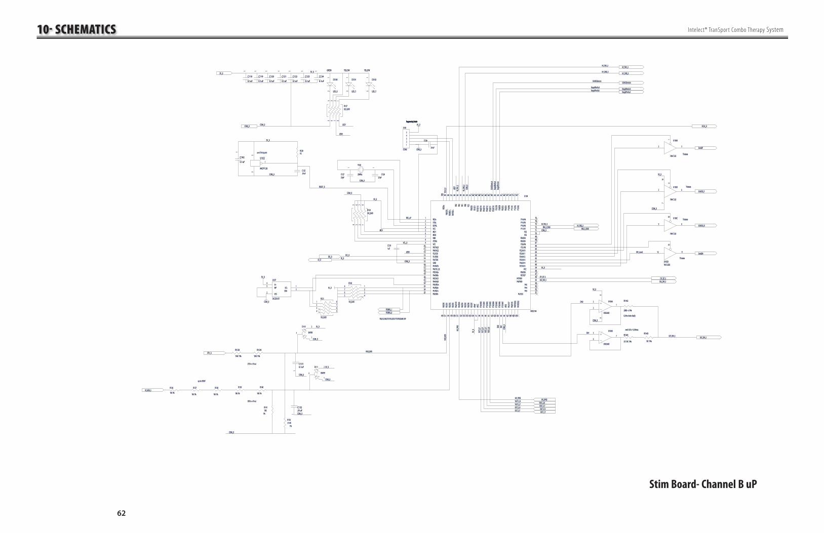
10- SCHEMATICS
62
Intelect® TranSpor t Combo Therapy System
Stim Board- Channel B uP
COM_BCOM_B
DO_BDO_BDI_BDI_B
STV_BSTV_B
VOUT_B_NVOUT_B_N
OUT_DRV_BOUT_DRV_B
IOUT_B_PIOUT_B_P
COM_BCOM_B
HV_IPKBHV_IPKB
VOUT_B_PVOUT_B_PIOUT_B_NIOUT_B_N
HV_IPKBHV_IPKBVOUT_B_NVOUT_B_NVOUT_B_PVOUT_B_P
IOUT_B_PIOUT_B_PIOUT_B_NIOUT_B_N
R134R134
1M 1%1M 1%
COM_BCOM_B
1
C131C1310.1uF0.1uF
R133R133
1M 1%1M 1%
OUT_DRV_BOUT_DRV_B
DO_BDO_BDI_BDI_B
SOURCEBmA/uASOURCEBmA/uA
RangeBNmA/uARangeBNmA/uARangeBPmA/uARangeBPmA/uA
SOURCEBmA/uASOURCEBmA/uA
RangeBNmA/uARangeBNmA/uARangeBPmA/uARangeBPmA/uA
Y100Y100
20Mhz20Mhz
1
C127C12727pF27pF
1
C128C12827pF27pF
COM_BCOM_B
R143R143
511K 1%511K 1%
R145R145
1K 1%1K 1%
R142R142
2K0 <1%2K0 <1%
3
21
84
U106AU106A
OPA2364IDOPA2364ID
5
67
U106BU106B
OPA2364IDOPA2364ID
DA0DA0
DA1DA1need 512K +/- 0.25%maxneed 512K +/- 0.25%max
0.25% or better ideally 0.25% or better ideally
COM_BCOM_B
5V_B5V_B
SinkBPSinkBP
SOURCEB_PSOURCEB_P
SinkBNSinkBNON_Low2ON_Low2
TristateTristate
TristateTristate
TristateTristate
TristateTristate
COM_BCOM_B
5V_B5V_B
SOURCEB_NSOURCEB_N
HVGB
_MON
HVGB
_MON
HV_IP
KBHV
_IPKB
VOUT
_B_N
VOUT
_B_N
VOUT
_B_P
VOUT
_B_P
IOUT_B
_PIOU
T_B_P
IOUT_B
_NIOU
T_B_N
STV_SET_BSTV_SET_BIDLE_DRV_BIDLE_DRV_B
SCLK
_BSC
LK_B Ran
geBNm
A/uA
RangeB
NmA/u
ARan
geBPm
A/uA
RangeB
PmA/u
A
SOUR
CEBmA
/uASO
URCEB
mA/uA
RES0
nRE
S0n
100
100
RESnRESn1
XTALXTAL2
EXTALEXTAL3
VCCVCC4
MD1MD15
MD0MD06
NMINMI7
STBYnSTBYn8
VCCVCC9
PA7/A23PA7/A231010
PA6/A22PA6/A221111
P52/SCK0P52/SCK01212
P51/RXD0P51/RXD01313
P50/TXD0P50/TXD01414
GNDGND1515
P97/WAITnP97/WAITn1616
P96/SYS_CLKP96/SYS_CLK1717
P95/ASnP95/ASn1818
P94/HWRnP94/HWRn1919
PA5/A21PA5/A212020
PA4/A20PA4/A202121
P93/RDnP93/RDn2222
P92/IRQ0nP92/IRQ0n2323
P91/IRQ1nP91/IRQ1n2424
P90/LWRnP90/LWRn2525
P60/CI
N0P60
/CIN0
2626
P61/CI
N1P61
/CIN1
2727
P62/CI
N2P62
/CIN2
2828
P63/CI
N3P63
/CIN3
2929
PA3/
A19
PA3/
A19
3030
PA2/CI
N10
PA2/CI
N10
3131
P64/CI
N4P64
/CIN4
3232
P65/CI
N5P65
/CIN5
3333
P66/CI
N6P66
/CIN6
3434
P67/CI
N7P67
/CIN7
3535
AVref
AVref
3636
AVCC
AVCC
3737
P70/
AN0
P70/
AN0
3838
P71/
AN1
P71/
AN1
3939
P72/
AN2
P72/
AN2
4040
P73/
AN3
P73/
AN3
4141
P74/
AN4
P74/
AN4
4242
P75/
AN5
P75/
AN5
4343
P76/
AN6
P76/
AN6
4444
P77/
AN7
P77/
AN7
4545
AVSS
AVSS
4646
PA1/
A17
PA1/
A17
4747
PA0/
A16
PA0/
A16
4848
P40/TX
D2(ir)
P40/TX
D2(ir)
4949
P41/RX
D2(ir)
P41/RX
D2(ir)
5050
P42/SCK2P42/SCK25151
P43P435252
P44P445353
P45P455454
P46/PWX0P46/PWX05555
P47/PWX1P47/PWX15656
PB7/D7PB7/D75757
PB6/D6PB6/D65858
VCCVCC5959
P27/A15P27/A156060
P26/A14P26/A146161
P25/A13P25/A136262
P24/A12P24/A126363
P23/A11P23/A116464
P22/A10P22/A106565
P21/A9P21/A96666
P20/A8P20/A86767
PB5/D5PB5/D56868
PB4/D4PB4/D46969
VSSVSS7070
VSSVSS7171
P17/A7P17/A77272
P16/A6P16/A67373
P15/A5P15/A57474
P14/A4P14/A47575
P13/
A3P1
3/A3
7676P1
2/A2
P12/
A27777
P11/
A1P1
1/A1
7878P1
0/A0
P10/
A07979
PB3/
D3PB
3/D3
8080PB
2/D2
PB2/
D28181
P30/
D8P3
0/D8
8282P3
1/D9
P31/
D98383
P32/
D10
P32/
D10
8484P3
3/D1
1P3
3/D1
18585
P34/
D12
P34/
D12
8686P3
5/D1
3P3
5/D1
38787
P36/
D14
P36/
D14
8888P3
7/D1
5P3
7/D1
58989
PB1/
D1PB
1/D1
9090PB
0/D0
PB0/
D09191
VSS
VSS
9292P8
0P8
09393
P81
P81
9494P8
2P8
29595
P83
P83
9696P84
/TXD1
/..P84
/TXD1
/..9797
P85/RX
D1/..
P85/RX
D1/..
9898P86
/SCK1/
..P86
/SCK1/
..9999 U104U104
H8S2144H8S2144
5V_B5V_B
RES_uPRES_uP
MD1MD1
5V_B
5V_B
5V_B5V_B
COM_
BCO
M_B
COM_BCOM_B
COM_BCOM_B
LED5LED5
COM_
BCO
M_B
DA1
DA1
DA0
DA0
18273645
R130R130
10K_QUAD10K_QUAD
18
27
36
45
R129R12910K_QUAD10K_QUAD
COM_BCOM_B
HVGB_MONHVGB_MON
COM_BCOM_B
5V_B5V_B
1
2
3
D110D110
BAV99BAV99
1
23
U102U102
MCP120MCP120
COM_BCOM_B
5V_B5V_B
use 4.75V trip pointuse 4.75V trip point
5V_B5V_B5V_B5V_B
COM_BCOM_B
1
C120C120
0.1uF0.1uF
1
C121C121
0.1uF0.1uF
1
C122C122
0.1uF0.1uF
1
C123C123
0.1uF0.1uF
1
C124C124
0.1uF0.1uF
12
DS100DS100
LED_GLED_G
12
DS101DS101
LED_YLED_Y
LED5LED5
12
DS102DS102
LED_YLED_Y
LED7LED7
18
27
36
45
R127R1272K2_QUAD2K2_QUAD
GREENGREEN YELLOWYELLOW YELLOWYELLOW
HV_MON_BHV_MON_BR140R140
1M 1%1M 1%
1
C132C132.01uF.01uF
R139R139
1M 1%1M 1%
up to 500V up to 500V COM_BCOM_B
1
2
3
D111D111
BAV99BAV99
5V_B5V_B
COM_BCOM_B
LED7
LED7
HV_TRG1_BHV_TRG1_B
HV_CHRG_BHV_CHRG_B
HV_TRG1_BHV_TRG1_B
HV_CHRG_BHV_CHRG_B
HV_TR
G1_B
HV_TR
G1_B
HV_CH
RG_B
HV_CH
RG_B
HV_TRG2_BHV_TRG2_B
1
C119C119
0.1uF0.1uF
1
C118C118
0.1uF0.1uF
R141R14110K10K
R135R13527.4K27.4K
HV_TRG2_BHV_TRG2_B
375V in = 5V out375V in = 5V out
505V in = 5V out505V in = 5V out
C125C125.01uF.01uF
R128R1281K1K
C126C126
.01uF.01uF
1%1%
1%1%
C129C1291uF1uF
R138R138
1M 1%1M 1%
R137R137
1M 1%1M 1%
VCL_BVCL_B
R136R136
1M 1%1M 1%
COM_BCOM_B
Programming HeaderProgramming Header
12345
J100J100
CON5CON5
5V_B5V_B
STV_SET_BSTV_SET_BIDLE_DRV_BIDLE_DRV_B
Programming HeaderProgramming Header
FDBKB_0FDBKB_0FDBKB_1FDBKB_1
SCLK_BSCLK_B
RESET_BRESET_B
P90,91,92 MUST BE PULLED UP TO PROGRAM CHIPP90,91,92 MUST BE PULLED UP TO PROGRAM CHIP
5V_B5V_B
1
2 3
U105AU105A
74HC12574HC125
4
5 6
14147
U105BU105B
74HC12574HC125
1010
9 8
U105CU105C
74HC12574HC125
1313
1212 1111
U105DU105D74HC125DB74HC125DB
EMG_B_50/60EMG_B_50/60EMG_B_50/60EMG_B_50/60
1
C162C162
0.1uF0.1uF
COM_BCOM_B
5V_B5V_B
V+V+4
SCLSCL1
SDASDA3
WPWP5
VSSVSS2
U107U107
24LC02B-I/OT24LC02B-I/OT1 82 73 64 5
R131R131
10K_QUAD10K_QUAD

10- SCHEMATICS
63
Intelect® TranSpor t Combo Therapy System
Stim Board- Channel B
Stim Output
1
23
Q117Q117BSP299BSP299
FDBKB_0FDBKB_0
1
23
Q118Q118BSP319BSP319
1
23
Q111Q111
BSP255BSP255
FDBKB_1FDBKB_1
1
23
Q122Q122BSP255BSP255
R174R1742.2R 1%2.2R 1%
1
23
Q128Q128
BSP299BSP299
R192R192100K 1%100K 1%R163R163
100K 1%100K 1%
1
23
Q129Q129
BSP319BSP319
R203R2032.2R 1%2.2R 1%
IOUT_B_PIOUT_B_P
R187R187
665 1%665 1%
IOUT_B_NIOUT_B_N
R188R188
10R 1W 1%10R 1W 1%
VOUT_B_PVOUT_B_P
R178R178
2K2K
VOUT_B_NVOUT_B_N
R173R1732K 1%2K 1%
R202R2022K 1%2K 1%
5
67
U112BU112B
TLC2274ACDTLC2274ACD5
67
U110BU110B
TLC2272ACDTLC2272ACD
3
21
84
U110AU110A
TLC2272ACDTLC2272ACD
SinkBPSinkBP
1010
98
U112CU112C
TLC2274ACDTLC2274ACD
R197R197
1M 1%1M 1%
R167R167
27.4K 1%27.4K 1%
RangeBPmA/uARangeBPmA/uA
R170R17027.4K 1%27.4K 1%
R168R168
1M 1%1M 1%
R196R196
27.4K 1%27.4K 1%1
C139C13910nF10nF R222R222
27.4K 1%27.4K 1%
RangeBNmA/uARangeBNmA/uA
R221R2216.81K6.81K
R227R2276.81K6.81K
SinkBNSinkBN
R228R228
27.4K 1%27.4K 1%
R181R181
10K 1%10K 1%
R182R18210K10K
R220R220
10K10K
STV_BSTV_B
R171R1716.81K6.81K
OUT_DRV_BOUT_DRV_B
R185R185
6.81K6.81K
1
C141C141
10nF10nF
R158R158
665 1%665 1%
IDLE_DRV_BIDLE_DRV_B
R159R159
10R 1W 1%10R 1W 1%
R155R155
6.81K6.81K
1
C134C134
10nF10nF
1010
98
U111CU111C
TLC2274ACDTLC2274ACD
5
67
U111BU111B
TLC2274ACDTLC2274ACD
STIMB_NSTIMB_N
R191R191100K 1%100K 1%
STIMB_PSTIMB_P
R162R162100K 1%100K 1%
1C145C145
100pF100pF
1C138C138
100pF100pF
1
23
Q120Q120
BSP255BSP255
1
23
Q109Q109BSP255BSP255
1
3ncnc
2
D119D119BZX84C10BZX84C10
1
3
ncnc2
D120D120
BZX84C10BZX84C10
1
3
ncnc2
D118D118
BZX84C10BZX84C10
1
C140C140
27pF27pF
1
2
Q107Q107
FMMTA42FMMTA42
R151R151
27.4K27.4K
R175R175200 1%200 1% R204R204
200 1%200 1%
R179R179
2K2K
R201R201
27R27R
A0A01
N01N012
GND
GND
3
N03N034
ENEN5
V+V+6
N04N047
COMCOM8
N02N029
A1A11010
U109U109
MAX4634MAX4634
R177R1771K1K R194R194
10K10K
R193R1931.07K1.07KR165R165
10K10K
R164R1641.07K 1%1.07K 1%
1
2 Q125Q125
FMMTA42FMMTA42
1
2Q124Q124
FMMTA42FMMTA42
R190R190
10K10K
R161R161
10K10K
1
2
Q113Q113
FMMTA42FMMTA421
2
Q114Q114
FMMTA42FMMTA42
R152R152
100K100K
3
21
41111
U111AU111A
TLC2274ACDTLC2274ACD
R205R20510K10K
C149C1491uF/10V1uF/10V
R208R2081M1M
COM_BCOM_B
R207R207
10K10K
1212
13131414
U111DU111D
TLC2274ACDTLC2274ACDC152C1521uF/10V1uF/10V
R214R2141M1M
R213R213
10K10K
R211R211
10K10K
3
21
41111
U112AU112A
TLC2274ACDTLC2274ACDC155C1551uF/10V1uF/10V
R219R219
511K511K
R226R226
10K10K
1212
13131414
U112DU112D
TLC2274ACDTLC2274ACD
C158C158
1uF/10V1uF/10V
R225R225511K511K
R217R217
10K10K
R223R223
10K10K
R215R21510K10K
R216R216
27.4K27.4K
R210R210
27.4K27.4KR209R20910K 1%10K 1%
C153C153
470pF/200V470pF/200V
C156C156470pF/200V470pF/200V
Q127Q127
2N70022N7002
R195R195
1K1K
R198R198
2K2K
1
23
Q126Q126BSP299BSP299
Q116Q116
2N70022N7002
R166R166
1K1K
R169R169
2K2K
1
2 3
Q115Q115BSP299BSP299
C137C137
100pF100pF
C144C144
100pF100pF
R206R206
10K10K
C147C147100pF100pF
R212R212
10K10K
11
22
C150C150
100pF100pF
R218R218
10K10K
R224R224
10K10K
R153R153200K200K
C142C142
22pF/200V22pF/200V
C143C143
22pF/200V22pF/200V
C135C13522pF/200V22pF/200V
C136C13622pF/200V22pF/200V
Q119Q119
FMMT4403FMMT4403
R154R1544R7 1W 5%4R7 1W 5%
R184R1846.81K6.81K
R183R1834R7 1W 5%4R7 1W 5%
R186R1863.30K 1%3.30K 1%
R157R157
3.30K 1%3.30K 1%
R160R160
27R27R
COM_BCOM_B
R189R189
27R27R
R180R180
27.4K 1%27.4K 1%
COM_BCOM_B
COM_BCOM_B
5V_B5V_B
R176R1761K 1%1K 1%
COM_BCOM_B
5V_B5V_B
COM_BCOM_B
R172R172
27R27R
COM_BCOM_B
COM_BCOM_B
COM_BCOM_B
COM_BCOM_B
COM_BCOM_B
5V_B5V_B5V_B5V_B
COM_BCOM_B
COM_BCOM_B
Q110AQ110A
BC807UBC807U
Q110BQ110BBC807UBC807U
COM_BCOM_B
R156R1566.81K6.81K
Q108Q108
FMMT4403FMMT4403
COM_BCOM_B
COM_BCOM_B
Q121BQ121B
BC807UBC807U
Q121AQ121ABC807UBC807U
COM_BCOM_BCOM_BCOM_B
5V_B5V_B
COM_BCOM_B
SOURCEB_PSOURCEB_P SOURCEB_NSOURCEB_N
5V_B5V_B
COM_BCOM_B
COM_BCOM_B
SOURCEBmA/uASOURCEBmA/uA
5V_B5V_B
COM_BCOM_B
C148C14810 pF10 pF
C151C15110 pF10 pF
C154C15410 pF10 pF
C157C15710 pF10 pF
1 2
3
D121D121BAV99BAV99
1 2
3
D122D122BAV99BAV99
1 2
3
D123D123BAV99BAV99
1 2
3
D124D124BAV99BAV99
16
D112AD112ACMXD2004CMXD2004
25
D112BD112BCMXD2004CMXD2004
34
D112CD112CCMXD2004CMXD2004
16
D115AD115ACMXD2004CMXD2004
25
D115BD115BCMXD2004CMXD2004
34
D115CD115CCMXD2004CMXD2004
C159C15947 pF47 pF
STIMB_NSTIMB_N
STIMB_NSTIMB_N
STIMB_PSTIMB_P
STIMB_PSTIMB_PC160C160
1000 pF 250 VAC1000 pF 250 VAC
R230R230
100R 0.25W100R 0.25W
4
31
52
U108U108
OPA364OPA364
Q123Q123FZT657CTFZT657CT
Q112Q112
FZT657CTFZT657CT

10- SCHEMATICS
64
Intelect® TranSpor t Combo Therapy System
Stim Board- Channel B
ISO Power
/TXD_B/TXD_B
5V_B5V_B
COM_BCOM_BPWR_uP_BPWR_uP_B
GNDGND
RXD_BRXD_B
DI_BDI_B
DO_BDO_B
/CHCLK/CHCLKSCLK_BSCLK_B
a1a11
k1k12
k2k23
a2a24
VccVcc8
O1O17
O2O26
GNDGND5
U9U9
OPTO_HPCL2630OPTO_HPCL2630
a1a11
k1k12
k2k23
a2a24
VccVcc8
O1O17
O2O26
GNDGND5
U10U10
OPTO_HPCL2630OPTO_HPCL2630
5V_B5V_B
COM_BCOM_B
COM_BCOM_B
5V5V
12
R29R2910K10K
+C21C21
1uF 10V1uF 10V +C100C100
1uF 10V1uF 10V
5V in - 5V out @ 1W converter 5V in - 5V out @ 1W converter 1
23
Q3Q3BSP319BSP319
5V5V5V_B5V_B
R101R10110K10K
R102R10210K10K
R103R103470R470R
GNDGND
FB100FB100
120120
Q100Q100
2N70022N7002
+ IN+ IN1414
-IN-IN1
+OUT+OUT8
-OUT-OUT1010
COMCOM9
NCNC7
PS1PS1
26D-05S05N26D-05S05N
GNDGND

10- SCHEMATICS
65
Intelect® TranSpor t Combo Therapy System
24V24V24V24V
1 2 3 4
5678
STIMB_NSTIMB_N
STIMB_PSTIMB_P
R100R1001K 5W axial1K 5W axial
HVGB_NHVGB_N
HVGB_PHVGB_P
32
4
67
51
8
K3K3
DPDT - 24VDPDT - 24V
32
4
67
51
8
K4K4
DPDT - 24VDPDT - 24V
32
4
67
51
8
K8K8
DPDT - 24VDPDT - 24V
TestLoad/PatientTestLoad/Patient
HV+/HV-HV+/HV-
STIM/HVSTIM/HV
24V24V
24V24V
24V24V
CHB_Out_-CHB_Out_-
CHB_Out_+CHB_Out_+
CH1_Out_+CH1_Out_+
CH2_Out_-CH2_Out_-
CH2_Out_+CH2_Out_+
CH1_Out_-CH1_Out_-
L105L105
INDUCTOR2INDUCTOR2
L106L106
INDUCTOR2INDUCTOR2
1234
J104J104CON4CON4
1234
J101J101
CON4CON4
PLASTICS ONEPLASTICS ONE
38319 JACK38319 JACK3
2
4
1
VIEW FROM FRONTVIEW FROM FRONT
GNDGND
IN 1IN 11
IN 2IN 22
IN 3IN 33
IN 4IN 44
IN 5IN 55
IN 6IN 66
IN 7IN 77
COMMONCOMMON8
CLAMPCLAMP9
OUT 7OUT 71010
OUT 6OUT 61111
OUT 5OUT 51212
OUT 4OUT 41313
OUT 3OUT 31414
OUT 2OUT 21515
OUT 1OUT 11616
U8U8
ULN2003L(16)ULN2003L(16)
24V24V/ENB/ENB
STIM/TEST_BSTIM/TEST_B
HV/STIM_BHV/STIM_BPOS/NEG_HV_BPOS/NEG_HV_B
STIM/TEST_BSTIM/TEST_B
HV/STIM_BHV/STIM_BPOS/NEG_HV_BPOS/NEG_HV_B
ENBENB
STIMA_+STIMA_+
STIMA_-STIMA_-
GNDGND
GNDGND
ENBENB
TEST/STIM_BTEST/STIM_B
TEST/STIM_BTEST/STIM_B
STIM/HV_BSTIM/HV_B
NEG/POS_HV_BNEG/POS_HV_B
/ENB/ENB
C161C161
.001uF.001uFGNDGND
Stim Board- Channel B
Relays

10- SCHEMATICS
66
Intelect® TranSpor t Combo Therapy System
Nominal 0 to 200VNominal 0 to 200V
CMP
CMP
1
-2
IsensIsens3
T4
VeVe5
OUTOUT6VcVc
7
VrVr8
U11U11
UCC3803DUCC3803D
1D100D100
ES1DES1D
1 D101D101
ES1DES1D
C101C101
10p/200V10p/200V
C102C10210p/200V10p/200V
R104R104
100R/.25W100R/.25W
R105R105
100R/.25W100R/.25WQ6Q6
IRFR120NIRFR120N
1D10D10
10MQ100N10MQ100N
D9D9
2EZ62D5MSCT2EZ62D5MSCT
R38R38
27R27R
R39R39
1K1K
1
C30C30470pF470pF
1
C31C31100pF100pF
R36R36
2K2K
R37R37
1K1K
1
C28C28
0.1uF0.1uF
1
C29C290.1uF0.1uF
R34R34100k100k
1
C26C260.1uF0.1uF
1
C32C320.1uF0.1uF
1
C22C22
0.1uF0.1uF
L2L2
3u3/1.1A3u3/1.1A
+C23C23
2u2/35V2u2/35V
24V24V
/ENB/ENB
GNDGND
1
C24C24
0.1uF0.1uF
+ C103C103
10u/100V10u/100V
+ C104C104
10u/100V10u/100V
+ C105C105
10u/100V10u/100V
+ C106C106
10u/100V10u/100V
C107C107
22nF/200V22nF/200V
C108C108
22nF/200V22nF/200VR35R3516.5K16.5K
1
R40R400.2R/1W0.2R/1W
24V24V
/ENB/ENB
GNDGND
COM_BCOM_B
STV_BSTV_B
5V5V5V5V
5V5V
1
2
Q5Q5
FMMT2222ACTFMMT2222ACT
12
+
C25C25
6u8/35V6u8/35V
+C27C27
2u2/252u2/25
C109C10910u/100V10u/100V
C110C11010u/100V10u/100V
C111C11110u/100V10u/100V
C112C11210u/100V10u/100V
L101L101
10uH/0.3A10uH/0.3A
HV_CHRG_BHV_CHRG_B
R33R33
100k100k
5V_B5V_B
HV_MON_BHV_MON_B
HV_IPKBHV_IPKB
HVGB_NHVGB_N
HVGB_PHVGB_P
1
R116R1161K1K 1
D102D102US1JUS1J
1
D106D106US1JUS1J
12
3
Q105Q105X0202MNX0202MN
HV_TRG2_BHV_TRG2_B
1
D105D105US1JUS1J
1
D104D104US1JUS1J
1
R118R1181K1K
1
R121R1211R51R5
1
R119R1191.1K1.1K
12
3
Q106Q106X0202MNX0202MN
1
R122R1221K1K
HV_TRG1_BHV_TRG1_B
C116C116
.015 / 600V.015 / 600V
C115C115
.01/ 600V.01/ 600V
R117R1171K1K
Q104Q104
PHT1N60RPHT1N60R
L102L102
100 mH100 mH
D103D103US1JUS1J
50mA Ipk50mA Ipk
R107R107100K100K
R108R108100k100k
R109R109100k100k
R110R110100k100k
R111R1116.49K6.49K
STV_SET_BSTV_SET_BR112R112
49.9K49.9K
C113C113
0.1uF0.1uF
R115R115180R180R
R114R114
2.2K2.2K
HiVolt OutputHiVolt Output
HiVolt Voltage FeedbackHiVolt Voltage Feedback
HiVolt Current FeedbackHiVolt Current Feedback
255V out = 5V in255V out = 5V in
PWM input to control output voltagePWM input to control output voltage
Q4Q4
FMMT2907ACTFMMT2907ACT R32R32
820 1/2W820 1/2W
R31R3130K30K
R30R305.6K5.6K
R113R113200K200K
FB101FB101
1K1KFB102FB102
1K1K
3
21
84
U101AU101A
TLC2272ACDTLC2272ACD
5
67
U101BU101B
TLC2272ACDTLC2272ACDC117C117
.01uF/50V.01uF/50V
R125R1255.11K5.11K
R123R12310K10K
R124R124
10K10K
1
R126R1261M1M
C114C114
220pF/50V220pF/50V
R106R106
0 OHM0 OHM
Q103Q103FZT757FZT757
Q102Q102FZT657CTFZT657CT
1%1%
1%1%
1%1%
1%1%
1%1%
1%1%
1%1%
1
R120R1201.1K1.1K
1%1%
1%1%
GNDGND
GNDGND
5V_B5V_B
5V_B5V_B
5V_B5V_B
HV_IPKBHV_IPKB
5V_B5V_B
GNDGND
1
3
6
4
U12U12
TLP181TLP181
1
2 7
8
5
6
T1T1
TRANS EPR STIMTRANS EPR STIM
1
2
Q101Q101
FMMT2222ACTFMMT2222ACT
HV_MON_BHV_MON_B
COM_BCOM_B
STV_BSTV_B
123
D107D107BAV99BAV99
1 2
3
D108D108BAV99BAV99
4
31
52
U100U100
OPA364OPA364
C60C60
470pF 200V470pF 200V
R65R65220220
R64R64220220
C167C167.01uF.01uF
C168C168.01uF.01uF
C169C169.01uF.01uF
GNDGND
FB103FB103
Stim Board- Channel B
Stim Power

67
Intelect® Transpor t Combo Therapy System
Chattanooga Group, a division of Encore Medical, L. P. ("Company"), warrants that the Intelect Transport Combo Therapy System ("Products") are free of defects in material and workmanship. This warranty shall remain in effect for one year (12 months) from the date of original consumer purchase. If these Products fail to function during the one year warranty period due to a defect in material or workmanship, at the Company's option, the Company or the selling dealer will repair or replace the respective Product without charge within a period of thirty days from the date on which the Product is returned to the Company or the dealer.
All repairs to the Product must be performed by a service center certified by the Company. Any modifications or repairs performed by unauthorized centers or groups will void this warranty.
The warranty period for certain accessories is 180 days. Accessories consist of Lead Wires, Electrodes, and Nylatex®.
The warranty period for the Battery and Ultrasound Applicators is one year (12 Months).
This Warranty Does Not Cover:
• Replacement parts or labor furnished by anyone other than the Company, the selling dealer, or a certified Company service technician.
• Defects or damage caused by labor furnished by someone other than Company, the selling dealer, or a certified Company service technician.
• Any malfunction or failure in the Product caused by product misuse, including, but not limited to, the failure to provide reasonable and required maintenance or any use that is inconsistent with the Product User's Manual.
COMPANY SHALL NOT BE LIABLE IN ANY EVENT FOR INCIDENTAL OR CONSEQUENTIAL DAMAGES.Some locations do not allow the exclusion or limitation of incidental or consequential damages, so the above limitation or exclusion may not apply to you.
To obtain service from Company or the selling dealer under this warranty:
1. A written claim must be made within the warranty period to the Company or the selling dealer. Written claims made to the Company should be sent to:
Chattanooga Group
4717 Adams Road
Hixson, TN 37343 USA
Phone: 1-800-592-7329 or 1 423-870-2281
FAX: 1-423-875-5497
chattgroup.com
and
2. The Product must be returned to the Company or the selling dealer by the owner. A Return Authorization (RA) Number must be obtained before returning any product to the Company.
This warranty gives you specific legal rights and you may also have other rights which vary from location to location.
The Company does not authorize any person or representative to create for it any other obligation or liability in connection with the sale of the Product.
Any representative or agreement not contained in the warranty shall be void and of no effect.
THE FOREGOING WARRANTY IS IN LIEU OF ALL OTHER WARRANTIES, EXPRESSED OR IMPLIED, INCLUDING ANY WARRANTY OR MERCHANTABILITY OR FITNESS FOR A PARTICULAR PURPOSE.
11- WARRANTY


4717 Adams RoadP.O. Box 489Hixson, TN 37343 U.S.A.
1-800-592-7329
1-423-870-2281
1-423-875-5497 Fax
chattgroup.com28157A © 2007 Encore Medical, L.P.