Embed Size (px)
Citation preview
INTEL ME: FLASH FILE SYSTEM EXPLAINED
2
Contents
1. Introduction ................................................................................................................... 3
2. MFS Partition ................................................................................................................. 4
2.1. MFS Pagination ............................................................................................................ 4
2.2. Chunks ........................................................................................................................ 5
2.3. System Page ................................................................................................................ 5
2.4. Data Page .................................................................................................................... 6
2.5. Data Area .................................................................................................................... 6
2.6. System Area ................................................................................................................ 7
2.7. Data Extraction ............................................................................................................ 7
2.8. MFS Templates Statistics ............................................................................................... 8
3. MFS Usage ..................................................................................................................... 9
3.1. Special Files ................................................................................................................. 9
3.2. intel.cfg (fitc.cfg) Structure ......................................................................................... 10
3.3. MFS Folder (Directory) ................................................................................................ 11
3.4. Integrity, Encryption, Anti-Replay ................................................................................ 12
4. File System Security Keys .............................................................................................. 13
4.1. RPMC Keys ................................................................................................................ 13
4.2. Integrity and Confidentiality Keys ................................................................................ 13
4.3. Hardware Security Engines .......................................................................................... 13
4.4. Keys Derivation and Usage Practices ............................................................................ 14
5. Conclusion ................................................................................................................... 15
3
1. Introduction
The Intel Management Engine (ME) technology was introduced in 2005.
Though more than 10 years have passed, it is still very hard to find any official information about ME on the Internet. The purpose of this document is to
detail how ME 11.x stores its state on the Flash.
If you need background information, please refer to the following additional
materials:
1. Platform Embedded Security Technology Revealed
2. Intel ME Secrets
3. Intel ME: The Way of the Static Analysis
4. Intel ME 11.x Firmware Images Unpacker
The SPI (Serial Peripheral Interface) Flash chip contains BIOS, data related to
GbE (Gigabit Ethernet), ME Region, and so on.
If Intel ME 11.x Firmware Images Unpacker parses the ME region, the output
directory contains a file named *.MFS.part, which includes the MFS partition.
4
2. MFS Partition
The MFS partition stores a file system that contains ME-related data between
runs. MFS is designed with the view of the following Flash memory features:
Any byte could be written independently
Need erase (make all bits=1) before re-writing
Erasing with the precision of a block (e.g., 8K) only
Limited number of guaranteed erase cycles
o Usually between 10,000 and 1,000,000
o Inerasable block should be marked as “bad”
After extraction of binary resources from fit.exe, it is easy to find three files
that represent empty MFS containers:
AFS_region_256K.bin
AFS_region_400K.bin
AFS_region_1272K.bin
The container size is specified in the file name (256, 400, or 1272 KiB). The maximum number of files that can be stored in these containers is 512, 256,
and 1024 respectively.
2.1. MFS Pagination
All the cbMFS bytes of MFS could be considered as a set of separate nPages
with the size of MFS_PAGE_SIZE == 8192(0x2000) bytes each. The page size
is likely to equal the size of Erase Block, which is a Flash memory property.
#define MFS_PAGE_SIZE 0x2000
cbMFS = sizeof(MFS); // Size of MFS partition
nPages = cbMFS / MFS_PAGE_SIZE; // Total number of pages
At any specific moment, “nPages/12” pages store System information.
“nPages - nPages/12 – 1” pages contain files Data. One page is always
Empty.
nSysPages = nPages / 12; // Number of System pages
nDataPages = nPages - nSysPages – 1; // Number of Data pages
5
Each page starts with an 18-byte header:
typedef struct {
unsigned __int32 signature; // Page signature == 0xAA557887
unsigned __int32 USN; // Update Sequence Number
unsigned __int32 nErase; // How many times page was erased
unsigned __int16 iNextErase; // Index of Next-to-be-erased page
unsigned __int16 firstChunk; // Index of first chunk (for Data page)
unsigned __int8 csum; // Page Header checksum (for first 16 bytes)
unsigned __int8 b0; // Always 0
} T_MFS_Page_Hdr; // 18 == 0x12 bytes
The Empty page has an invalid sign field (!= 0xAA557887). The System page
always has 0 in the firstChunk field. All the other pages are Data pages.
2.2. Chunks
Each page contains several 66(0x42)-byte chunks. A chunk is an MFS’ primary
addressable (and modifiable) unit.
The first 64(0x40) bytes of each chunk are used for payload storing. The next two bytes store CCITT CRC-16 calculated from the chunk data and chunk
index.
#define MFS_CHUNK_SIZE 0x40
typedef struct {
unsigned __int8 data[MFS_CHUNK_SIZE]; // Payload
unsigned __int16 crc16; // Checksum
} T_MFS_Chunk; // 66 == 0x42 bytes
Note. Reversing CRC-16 allows easy calculation of the chunk index.
2.3. System Page
There is an array of 16-bit indices axIdx in the System page right after the
Page Header. The number of entries in axIdx equals to the number of chunks
+ 1. Each System page contains 120(0x78) chunks started from the
260(0x104) offset.
#define SYS_PAGE_CHUNKS 120
typedef struct {
T_MFS_Page_Hdr hdr; // Page header
unsigned __int16 axIdx[SYS_PAGE_CHUNKS+1]; // Obfuscated indices
T_MFS_Chunk chunks[SYS_PAGE_CHUNKS]; // System chunks
} T_MFS_System_Page;
nSysPageChunks = (MFS_PAGE_SIZE – sizeof(T_MFS_Page_Hdr) - 2) /
(2 + sizeof(T_MFS_Chunk)); // 120(0x78) chunks per System page
Initially, each axIdx entry contains the 0xFFFF value. The 0x8000 bit is
cleared for the entry that follows the last used entry. The next bit 0x4000 is
cleared for the used entries. Indices stored in axIdx are obfuscated by XORing
with dynamic secret. The secret value depends on the previous value from
6
axIdx. Its calculation involves the modified version of CRC-16 (stripped to 14
bits).
2.4. Data Page
There is the aFree byte array in the Data page immediately after the Page
Header. The number of entries in aFree equals to the number of chunks. Each
Data page contains 122(0x7A) chunks started from the 140(0x8C) offset.
#define DATA_PAGE_CHUNKS 122
typedef struct {
T_MFS_Page_Hdr hdr; // Page header
unsigned __int8 aFree[DATA_PAGE_CHUNKS]; // Free chunks map
T_MFS_Chunk chunks[DATA_PAGE_CHUNKS]; // Data chunks
} T_MFS_Data_Page;
nDataPageChunks = (MFS_PAGE_SIZE – sizeof(T_MFS_Page_Hdr)) /
(1 + sizeof(T_MFS_Chunk)); // 122(0x7A) chunks per Data page
Initially, each entry of aFree contains the 0xFF value. When a chunk is used, a
corresponding aFree entry is zeroed.
2.5. Data Area
All the chunks from Data pages build the Data area. Each Data page contains
chunks with sequential numbers starting from hdr.firstChunk. Minimal value
of the hdr.firstChunk field among all Data pages equals to nSysChunks
(logical number of chunks in the System area). Each Data area has only one
Data chunk with a specific index.
The total number of nDataChunks is calculated by multiplying the number of
Data pages and the number of chunks on a single Data page, which is
122(0x7A).
Data area capacity is calculated by multiplying the number of Data chunks and
the chunk payload size, which is 64(0x40) bytes.
nDataChunks = nDataPages * nDataPageChunks; // Number of Data chunks cbData = nDataChunks * MFS_CHUNK_SIZE; // Data area capacity
7
2.6. System Area
Unlike the Data area, System chunks are stored not sequentially but in accordance with an update order. A Chunk index for the System page is
derived from a corresponding value in axIdx. System chunks with a specific
index are not unique, but only the last entry can be used. To restore a proper
order, we need to handle System pages in accordance with USN growth.
The System area starts with 14-byte Volume Header:
typedef struct {
unsigned __int32 sign; // Volume signature == 0x724F6201
unsigned __int32 ver; // Volume version == 1
unsigned __int32 cbTotal; // Volume capacity (System area+Data area)
unsigned __int16 nFiles; // Number of file records
} T_MFS_Volume_Hdr; // 14 bytes
There is an array of 16-bit values aFAT right after Volume Header. The number
of entries in aFAT equals to the number of file records + the number of data
chunks.
typedef struct {
T_MFS_Volume_Hdr vol; // Volume header
unsigned __int16 aFAT[vol.nFiles+nDataChunks];//File Allocation Table
} T_MFS_System_Area;
2.7. Data Extraction
Low-level MFS implementation does not support file names. Files are identified
by numbers (from 0 to nFiles-1, inclusive). A file size is not stored explicitly
either.
To extract a file with the specific iFile number, it is necessary to:
1. Calculate the index in FAT: ind = aFAT[iFile]. The values 0x0000
(unused) and 0xFFFE (erased) mean that the file does not exist. The
value 0xFFFF means that the file is empty (length == 0).
2. Make sure that nFiles <= ind < len(aFAT).
3. Extract chunk data: data = dataChunk[ind - nFiles + nSysChunks].
4. Calculate the next index: ind = aFAT[ind].
5. If (0 < ind <= MFS_CHUNK_SIZE), then output first ind bytes of data
and stop processing.
6. Output all 64 bytes of data and proceed to step 2.
8
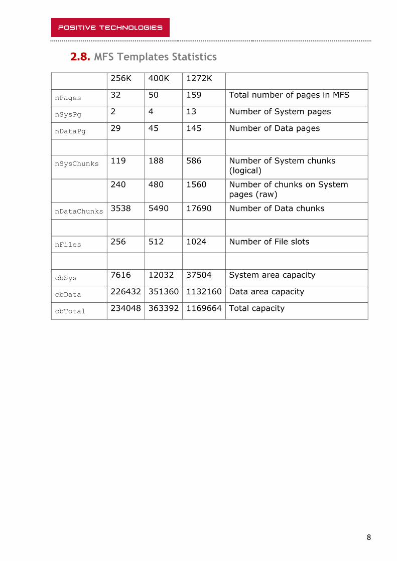
2.8. MFS Templates Statistics
256K 400K 1272K
nPages 32 50 159 Total number of pages in MFS
nSysPg 2 4 13 Number of System pages
nDataPg 29 45 145 Number of Data pages
nSysChunks 119 188 586 Number of System chunks
(logical)
240 480 1560 Number of chunks on System
pages (raw)
nDataChunks 3538 5490 17690 Number of Data chunks
nFiles 256 512 1024 Number of File slots
cbSys 7616 12032 37504 System area capacity
cbData 226432 351360 1132160 Data area capacity
cbTotal 234048 363392 1169664 Total capacity
9
3. MFS Usage
3.1. Special Files
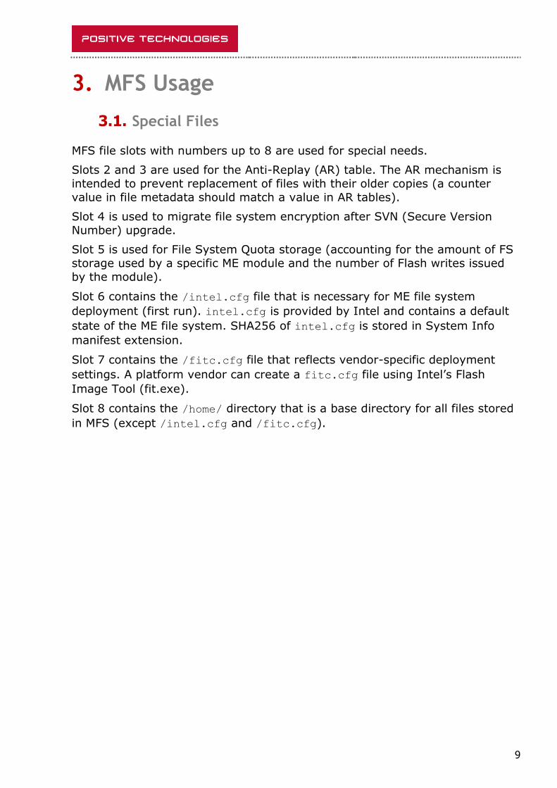
MFS file slots with numbers up to 8 are used for special needs.
Slots 2 and 3 are used for the Anti-Replay (AR) table. The AR mechanism is
intended to prevent replacement of files with their older copies (a counter
value in file metadata should match a value in AR tables).
Slot 4 is used to migrate file system encryption after SVN (Secure Version
Number) upgrade.
Slot 5 is used for File System Quota storage (accounting for the amount of FS
storage used by a specific ME module and the number of Flash writes issued
by the module).
Slot 6 contains the /intel.cfg file that is necessary for ME file system
deployment (first run). intel.cfg is provided by Intel and contains a default
state of the ME file system. SHA256 of intel.cfg is stored in System Info
manifest extension.
Slot 7 contains the /fitc.cfg file that reflects vendor-specific deployment
settings. A platform vendor can create a fitc.cfg file using Intel’s Flash
Image Tool (fit.exe).
Slot 8 contains the /home/ directory that is a base directory for all files stored
in MFS (except /intel.cfg and /fitc.cfg).

10
3.2. intel.cfg (fitc.cfg) Structure
File system configuration files are used for ME file system deployment. Both
intel.cfg and fitc.cfg have an identical structure.
A file system configuration file starts with a 32-bit value nRec representing the
number of records in a file. An array of fixed-size records aRec is the
following. All the other bytes in the configuration file contain file data.
typedef struct {
char name[12]; // File name
unsigned __int16 unused; // Always 0
unsigned __int16 mode; // Access mode
unsigned __int16 opt; // Deploy options
unsigned __int16 cb; // File data length
unsigned __int16 uid; // Owner User ID
unsigned __int16 gid; // Owner Group ID
unsigned __int32 offs; // File data offset
} T_CFG_Record; // 28 bytes
typedef struct {
unsigned __int32 nRec; // Number of records
T_CFG_Record aRec[nRec]; // Records
unsigned __int8 data[]; // Files data
} T_CFG;
The mode field of T_CFG_Record is a set of bit fields:
Lowest 9 bits (8..0) represent UNIX-like Read/Write/eXecute
permissions (rwx) for an owner, group, and others respectively.
Bit 9 is set for files that must have Integrity protection enabled.
Bit 10 is set for files that must have Encryption enabled.
Bit 11 is set for files that must have Anti-Replay protection enabled.
Bit 12 reflects a record type. It is set for a directory and cleared for an
ordinary file.
All other bits are always zeroed.
The opt field of T_CFG_Record is a set of bit fields too:
Bit 0 is set for records that can be overridden by a vendor using fitc.cfg.
Bit 1 is set for files updateable by the mca process.
Bits 3..2 are unknown up to now.
All other bits are always zeroed.
11
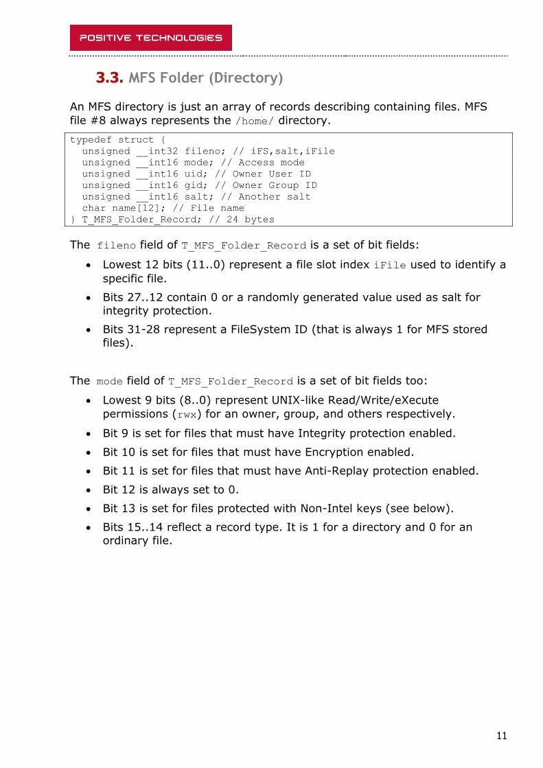
3.3. MFS Folder (Directory)
An MFS directory is just an array of records describing containing files. MFS
file #8 always represents the /home/ directory.
typedef struct {
unsigned __int32 fileno; // iFS,salt,iFile
unsigned __int16 mode; // Access mode
unsigned __int16 uid; // Owner User ID
unsigned __int16 gid; // Owner Group ID
unsigned __int16 salt; // Another salt
char name[12]; // File name
} T_MFS_Folder_Record; // 24 bytes
The fileno field of T_MFS_Folder_Record is a set of bit fields:
Lowest 12 bits (11..0) represent a file slot index iFile used to identify a
specific file.
Bits 27..12 contain 0 or a randomly generated value used as salt for
integrity protection.
Bits 31-28 represent a FileSystem ID (that is always 1 for MFS stored
files).
The mode field of T_MFS_Folder_Record is a set of bit fields too:
Lowest 9 bits (8..0) represent UNIX-like Read/Write/eXecute
permissions (rwx) for an owner, group, and others respectively.
Bit 9 is set for files that must have Integrity protection enabled.
Bit 10 is set for files that must have Encryption enabled.
Bit 11 is set for files that must have Anti-Replay protection enabled.
Bit 12 is always set to 0.
Bit 13 is set for files protected with Non-Intel keys (see below).
Bits 15..14 reflect a record type. It is 1 for a directory and 0 for an
ordinary file.
12
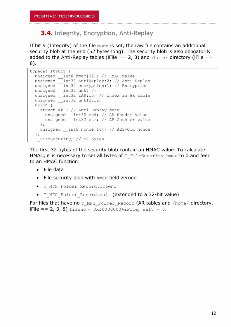
3.4. Integrity, Encryption, Anti-Replay
If bit 9 (Integrity) of the file mode is set, the raw file contains an additional
security blob at the end (52 bytes long). The security blob is also obligatorily
added to the Anti-Replay tables (iFile == 2, 3) and /home/ directory (iFile ==
8).
typedef struct {
unsigned __int8 hmac[32]; // HMAC value
unsigned __int32 antiReplay:2; // Anti-Replay
unsigned __int32 encryption:1; // Encryption
unsigned __int32 unk7:7;
unsigned __int32 iAR:10; // Index in AR table
unsigned __int32 unk12:12;
union {
struct ar { // Anti-Replay data
unsigned __int32 rnd; // AR Random value
unsigned __int32 ctr; // AR Counter value
};
unsigned __int8 nonce[16]; // AES-CTR nonce
};
} T_FileSecurity; // 52 bytes
The first 32 bytes of the security blob contain an HMAC value. To calculate
HMAC, it is necessary to set all bytes of T_FileSecurity.hmac to 0 and feed
to an HMAC function:
File data
File security blob with hmac field zeroed
T_MFS_Folder_Record.fileno
T_MFS_Folder_Record.salt (extended to a 32-bit value)
For files that have no T_MFS_Folder_Record (AR tables and /home/ directory,
iFile == 2, 3, 8) fileno = 0x10000000+iFile, salt = 0.
13
4. File System Security Keys
There are up to 10 security keys involved in protecting the MFS content.
4.1. RPMC Keys
Two of these keys (called RPMC HMAC keys) are used for handling RPMC
(Replay-Protected Monotonic Counter). RPMC is an optional feature of the SPI Flash chip helpful for Anti-Replay Protection implementation. If this feature is
not available, ME implements its own timer-based counter.
4.2. Integrity and Confidentiality Keys
MFS uses separate keys to protect Integrity and Confidentiality.
There are two sets of keys: Intel keys and Non-Intel keys. A proper set is
chosen accordingly with bit 13 (Non-Intel) of T_MFS_Folder_Record.mode.
Please note that such rare modules as sigma, ptt, dal_ivm, mca use Intel
keys. The majority of protected files (including AR tables and all directories)
use Non-Intel keys.
Derivation of security keys involves a 1-byte SVN (Secure Version Number) value, which is the property of ME Code Partition Directory Manifest. Keys
calculated for current SVN are called “Current keys”.
After SVN update (usually caused by fix of major security vulnerabilities), it
must be impossible to install ME firmware with previous SVN (without direct
writing SPI Flash with chip programmer). However, alteration of SVN causes alteration of related security keys. Therefore, a previous SVN value is stored in
the PSVN partition and used to calculate “Previous keys”. Having access to both “Previous” and “Current” keys allows migration of file system from old to
new keys.
4.3. Hardware Security Engines
ME has access to hardware implemented engines intended for AES, RSA, and Hash/HMAC calculation. Another hardware security module used by ME is
called SKS (presumably stands for Secure Key Storage).
SKS is able to store keys, provides AES/HMAC engines with access to stored
keys, but prevents extraction of the keys. Slots 1..11 can contain 128-bit
keys, while slots 12..21 are for 256-bit keys.
Access to hardware security engines is limited. Modules able to use them are
limited to ROM, bup, and crypto.
In addition, there is a GEN device that contains source material for keys calculation. GEN data seems to be unique for every computer. ROM accesses
GEN at an early execution stage and creates a copy of stored data. ROM uses
14
such data for keys derivation, but clears both GEN and copied data before
passing control to rbe (initial module from ME firmware).
It is interesting that before wiping GEN data and passing control to rbe, ROM
searches and executes the idlm module from the DMLP partition (if any
exists). Thus, idlm can access GEN data and perform any necessary operation
on it (ME 11.8 firmware was seen using that trick). For sure, the DLMP
partition must be properly signed with RSA-2048.
4.4. Keys Derivation and Usage Practices
Keys are usually derived in several steps:
1. ROM uses GEN data to obtain HMAC Key.
2. ROM derives Wrapping Key using HMAC Key. A resulting key is stored
in SKS.
3. ROM derives Root Key (which depends on SVN) using HMAC Key.
4. ROM wraps Root Key (using AES) and stores it in memory.
5. ROM wipes all intermediate keys (except Wrapping Key), GEN, and all
data copied from it.
6. ROM passes control to ME firmware.
7. The bup module unwraps Root Key and loads it into SKS (unwrapping
result can’t be stored outside SKS).
8. bup derives Integrity/Confidentiality keys using an SKS-stored Root
key.
9. bup wraps derived key and stores it in memory (or passes to another
module, e.g., vfs, if necessary).
10. bup wipes plaintext key.
To use wrapped key:
11. The bup/crypto module unwraps requested Integrity/Confidentiality
key and loads it into SKS.
12. Final HMAC/AES operation is performed using the key from SKS.
It is easy to see that Root Key is available in a non-wrapped form only during step 4, and there is no way to get it after the ROM execution is finished
(control is passed to ME firmware).
Final Integrity/Confidentiality keys are available in a non-wrapped form only
during step 9. However, anyone having ability to execute code with bup
privileges could re-calculate those keys by repeating steps 7 and 8.

15
5. Conclusion
Our research does not claim to be exhaustive or error-free.
Nevertheless, we hope that it could help researchers involved in studying
Platform security and ME internals.
16
Contacts
Email: [email protected] Twitter: @PTsecurity_UK Web: www.ptsecurity.com Blog: blog.ptsecurity.com
United Kingdom, London
361 King Street,
London, W6 9NA
+44 203 769 3606


![ME Health Monitoring System PPT[1]](https://img.pdfslide.us/doc/110x75/544d8bfaaf7959f7178b4be1/me-health-monitoring-system-ppt1.jpg)