Embed Size (px)
DESCRIPTION
Chapter No 2 Accessing the GPIO PinsLeverage the power of Intel Galileo to construct amazingly simple, yet impressive projectsFor more information : http://bit.ly/1Dz94Sa
Citation preview

C o m m u n i t y E x p e r i e n c e D i s t i l l e d
Leverage the power of Intel Galileo to construct amazingly simple, yet impressive projects
Intel Galileo Essentials
Richard G
rimm
ett
Intel Galileo Essentials
Intel Galileo Essentials provides step-by-step instructions on how to use the Galileo in Do-It-Yourself electronics projects. We begin by powering up the Galileo and loading the development system to get started. Post this, we look at GPIO capability in general along with the basics of programming the GPIO pins, also learning how to connect external HW to the GPIO pins. Moving on, we begin connecting a display to the Galileo, while learning the important points such as importing the support fi les, programming text and graphics, and getting input from a touchscreen. More signifi cantly, we start controlling motors, adding sensors, and learning how to communicate wirelessly with your Galileo projects.
We conclude by building a wide variety of projects with the Galileo such as controlling servos for walking robots, hacking toy robots with the Galileo, and creating an ROV (Remotely Operated Vehicle) with the Galileo.
Who this book is written forThis book is for anyone who has ever been curious about using the Intel Galileo to create electronics projects. Some programming background is useful, but if you know how to use a personal computer, with the aid of the step-by-step instructions in this book, you can construct complex electronics projects that use the Intel Galileo.
$ 29.99 US£ 18.99 UK
Prices do not include local sales tax or VAT where applicable
Richard Grimmett
What you will learn from this book
Access the Linux system that is the basis for Galileo to add even more complex hardware and software
Install and use the software development environment and connect to the Galileo and develop programs for it
Add a simple display to the Galileo
Connect external HW to the GPIO pins
Control DC motors with the Galileo
Add sensors to a Galileo-based project
Access your Galileo wirelessly
Understand the basics of sketches, include fi les, and HW support
Intel Galileo Essentials
P U B L I S H I N GP U B L I S H I N G
community experience dist i l led
Visit www.PacktPub.com for books, eBooks, code, downloads, and PacktLib.
Free Sample
In this package, you will find: • The author biography • A preview chapter from the book, Chapter 2 ‘Accessing the GPIO Pins’ • A synopsis of the book’s content • More information on Intel Galileo Essentials
About the Author Richard Grimmett has always been fascinated by computers and electronics from his very first programming project that used Fortran on punch cards. He has a bachelor's and master's degree in electrical engineering and a PhD in leadership studies. He also has 26 years of experience in electronics and computers. He possesses one of the original brick phones as well as a Google glass. He now teaches computer science and electrical engineering at Brigham Young University-Idaho, where his office is filled with his many robotics projects.
I would certainly like to thank my wife, Jeanne, and family for providing me with a wonderful, supportive environment that encourages me to take on projects like this. I would also like to thank my students; they show me that amazing things can be accomplished by those who are unaware of the barriers.
Intel Galileo Essentials Over the last few years, a number of important technological tools have been introduced that have enabled the migration of complex electronics projects from the University or Government Lab to almost anyone's project desk. The Galileo, an inexpensive processor system by Intel, is an example of one of these toolkits. This small, inexpensive, but powerful board can be used in a wide range of projects.
But just as important as the hardware is the community of developers who not only provide help in the area of software development, but also provide hardware add-ons for the processor board itself. Still, it can be a bit intimidating to start using Galileo to build your very own projects.
This book is designed to help anyone, even those with no programming background or experience, to be successful in building both simple but also quite complex projects. It will lead you through the process step by step so that your project designs can come to life. Hopefully, this book will inspire those with the imagination and creative spirit to build those wildly inventive designs that will revolutionize the world!
What This Book Covers Chapter 1, Getting Started with the Galileo, begins with a discussion of how to connect power and ends with a full system, configured and ready to begin connecting amazing devices and SW capabilities to fulfill almost any project.
Chapter 2, Accessing the GPIO Pins, shows you to how to access these pins, both input and output, so you can do all sorts of amazing things. One of the capabilities you'll need to complete your projects is a basic knowledge of how to access the GPIO pins so that you can access all sorts of additional hardware capabilities.
Chapter 3, Adding Display Functionality, shows you how the Galileo can be connected to a display so that you can both see output and also get input from a touchscreen. One of the first things you might want to do is to connect a display up to the Galileo.
Chapter 4, Controlling DC Motors, details how to control a DC motor so that the unit can drive wheels or tracks.
Chapter 5, Adding Sensors, shows you how to add IR, Sonar, and even a compass to your project.

Chapter 6, Remote Control, covers how to communicate wirelessly with your Galileo projects, as you may want to access your projects without connecting wires.
Chapter 7, Going Further with Galileo, introduces you to the Linux capabilities of the Galileo using the example of constructing a quadruped robot.
Chapter 8, Speech Output, covers how to make your project talk as an example of how to use free, open source software to add complex functionality to your projects. One of the amazing features of today's computer systems is the ability to provide output without a screen or keyboard.
Accessing the GPIO PinsNow that you are familiar with the Galileo IDE and know how to create, edit, and upload a program, this chapter will now focus on hardware. You'll learn about the capabilities of the General Purpose Input/Output (GPIO) pins and how you can connect to and access them via software. Specifi cally, you'll learn about the following:
• The GPIO pins, what they can and can't do• How to use and access them using some very basic circuits and very simple
programming examples that demonstrate how to make the Galileo access the outside world
The GPIO capability of the GalileoThe Galileo was built to model how the Arduino accesses the outside world. Much of that access should be through the GPIO pins. The Galileo comes with a standard set of 14 digital and 6 analog IO pins, along with some additional pins to provide power and serial IO. Fortunately, the pins are actually well labeled on the board itself.
Accessing the GPIO Pins
[ 24 ]
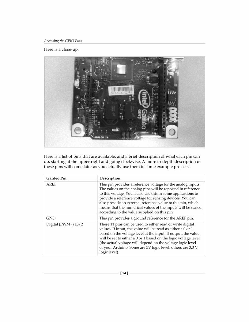
Here is a close-up:
Here is a list of pins that are available, and a brief description of what each pin can do, starting at the upper right and going clockwise. A more in-depth description of these pins will come later as you actually use them in some example projects:
Galileo Pin DescriptionAREF This pin provides a reference voltage for the analog inputs.
The values on the analog pins will be reported in reference to this voltage. You'll also use this in some applications to provide a reference voltage for sensing devices. You can also provide an external reference value to this pin, which means that the numerical values of the inputs will be scaled according to the value supplied on this pin.
GND This pin provides a ground reference for the AREF pin.Digital (PWM~) 13/2 These 11 pins can be used to either read or write digital
values. If input, the value will be read as either a 0 or 1 based on the voltage level at the input. If output, the value will be set to either a 0 or 1 based on the logic voltage level (the actual voltage will depend on the voltage logic level of your Arduino. Some are 5V logic level, others are 3.3 V logic level).
Chapter 2
[ 25 ]
Galileo Pin DescriptionDigital TX->1 This pin, and the RX pin next to it, provide a serial interface
that can be used to communicate with other devices.Digital RX->0 This pin, and the TX pin next to it, provide a serial interface
that can be used to communicate with other devices.Analog IN A5/A0 These pins do double duty. Normally, they are used as A/D
inputs to the Galileo to read continuous voltage values and turn them into integer values. However, they can also be used as Digital I/O, very similar to the Digital I/O pins.
Power Vin You can power the Galileo from this pin. This can be especially useful after you have uploaded your program. You can then disconnect the USB port and, when you apply voltage to this pin, your Galileo will boot and run the uploaded program. For the Gen1 board, this needs to be 5 volts. For the Gen2 board, you can use a voltage value from 7 to 12 Volts, so a wide variety of DC power adapter or battery configurations can be used.
Power GND This pin would give the ground connection associated with the Power Vin connection.
Power GND This is a ground normally associated with the Power 5V and Power 3.3V outputs.
Power 5V This is a voltage output set to 5 Volts.Power 3.3V This is a voltage output set to 3.3 Volts.RESET This pin will reset the processor, which will cause the
program to run from the beginning.IOREF This provides either a 3.3V, or 5 V reference, indicating the
logic level of the board.
Accessing the GPIO Pins
[ 26 ]
Using the GPIO pinsNow that you are aware of all the GPIO capabilities, you can start putting them to work. In order to do this, it is best to purchase a small breadboard and some jumper wires; this will make connecting to the outside world easier. Here is a picture of such a breadboard:
They are easy to fi nd, you can purchase one at almost any electronics store, or on any electronic online sites. You'll need some jumper wires to connect from the Galileo to the breadboard. The jumper wires you want are the Male-to-Male solder-less jumper wires. Here is a picture of this sort of wire:
These jumper cables plug easily into the header pins on the Galileo and the breadboard. Now that you have the cables and the breadboard, you can start accessing and controlling hardware.
Chapter 2
[ 27 ]
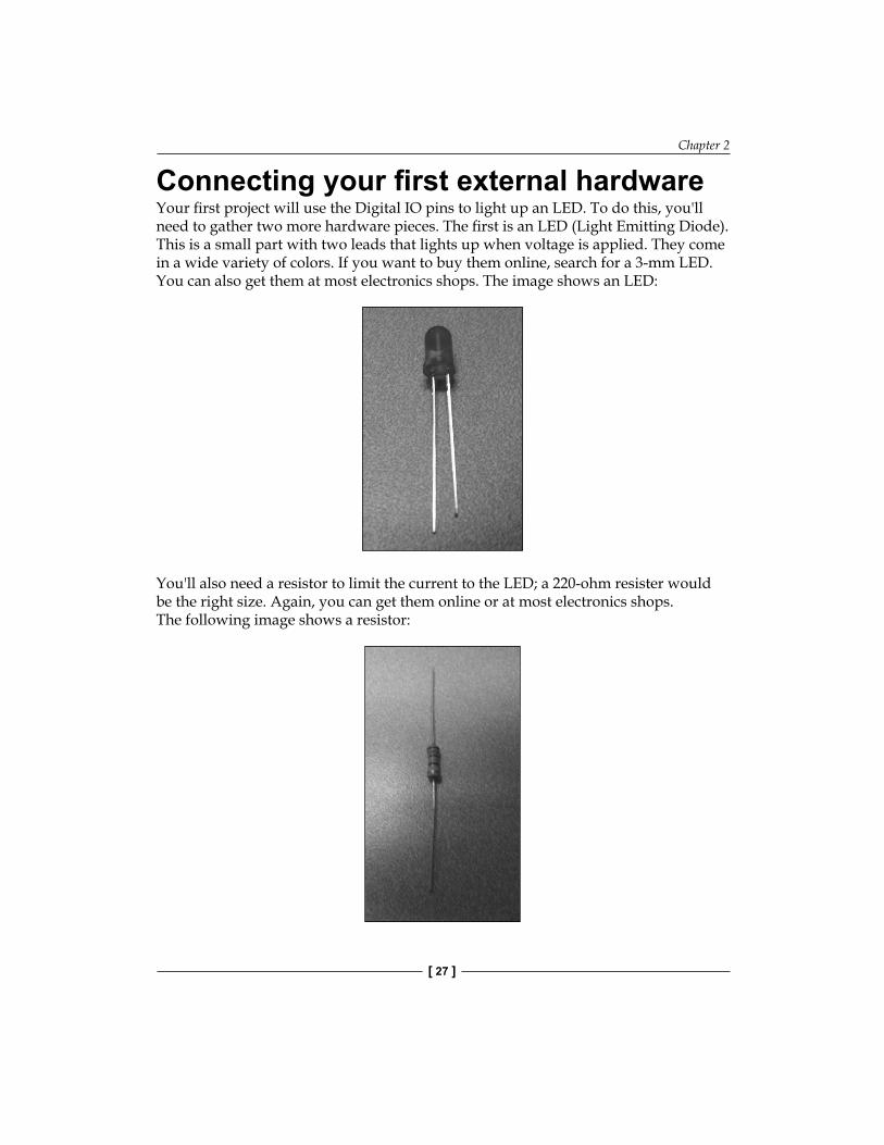
Connecting your fi rst external hardwareYour fi rst project will use the Digital IO pins to light up an LED. To do this, you'll need to gather two more hardware pieces. The fi rst is an LED (Light Emitting Diode). This is a small part with two leads that lights up when voltage is applied. They come in a wide variety of colors. If you want to buy them online, search for a 3-mm LED. You can also get them at most electronics shops. The image shows an LED:
You'll also need a resistor to limit the current to the LED; a 220-ohm resister would be the right size. Again, you can get them online or at most electronics shops. The following image shows a resistor:
Accessing the GPIO Pins
[ 28 ]
If you get three LEDs and resistors, you can exercise three of the Digital IO pins.
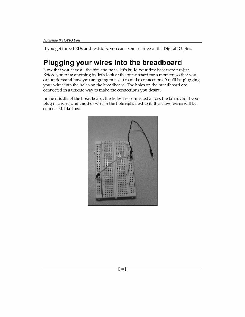
Plugging your wires into the breadboardNow that you have all the bits and bobs, let's build your fi rst hardware project. Before you plug anything in, let's look at the breadboard for a moment so that you can understand how you are going to use it to make connections. You'll be plugging your wires into the holes on the breadboard. The holes on the breadboard are connected in a unique way to make the connections you desire.
In the middle of the breadboard, the holes are connected across the board. So if you plug in a wire, and another wire in the hole right next to it, these two wires will be connected, like this:
Chapter 2
[ 29 ]
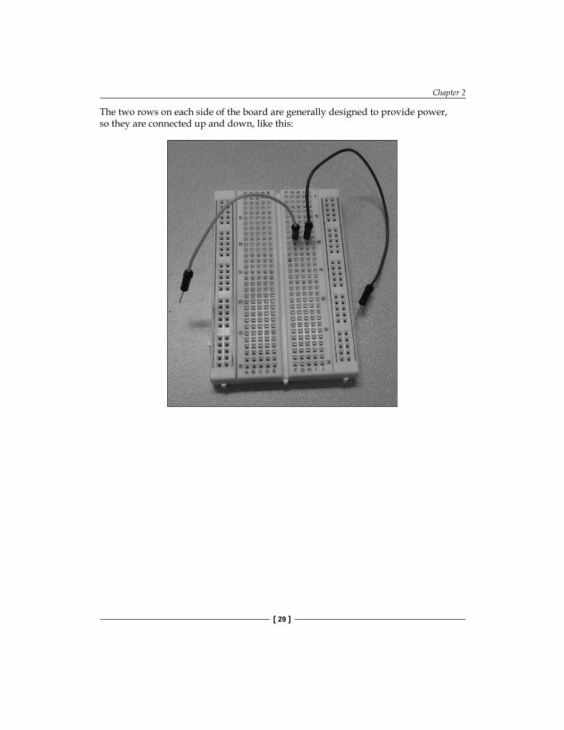
The two rows on each side of the board are generally designed to provide power, so they are connected up and down, like this:
Accessing the GPIO Pins
[ 30 ]
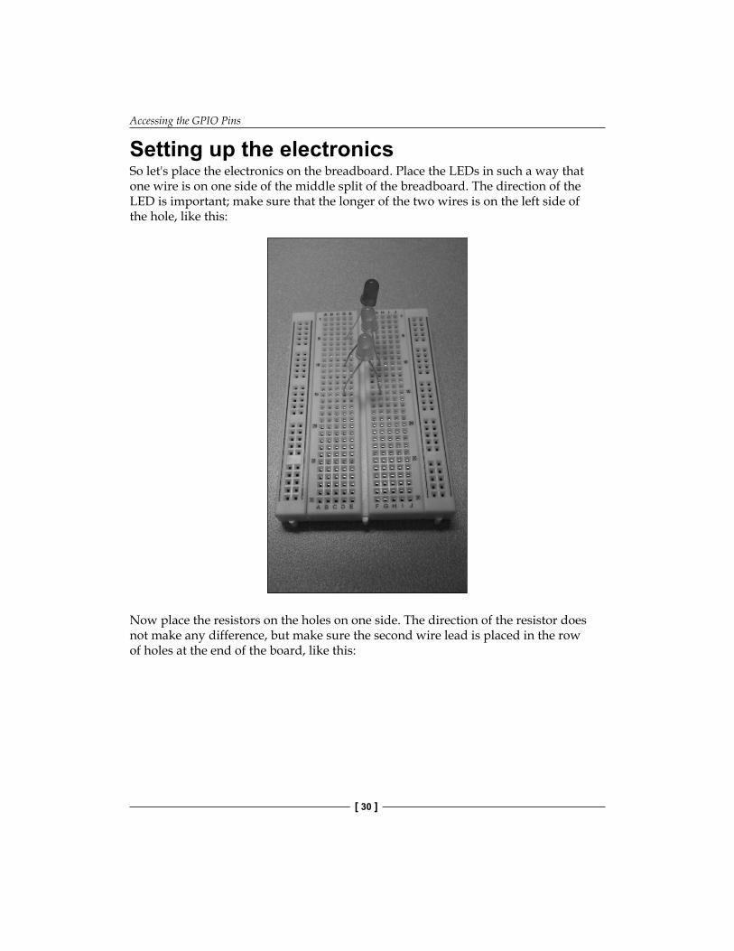
Setting up the electronicsSo let's place the electronics on the breadboard. Place the LEDs in such a way that one wire is on one side of the middle split of the breadboard. The direction of the LED is important; make sure that the longer of the two wires is on the left side of the hole, like this:
Now place the resistors on the holes on one side. The direction of the resistor does not make any difference, but make sure the second wire lead is placed in the row of holes at the end of the board, like this:
Chapter 2
[ 31 ]
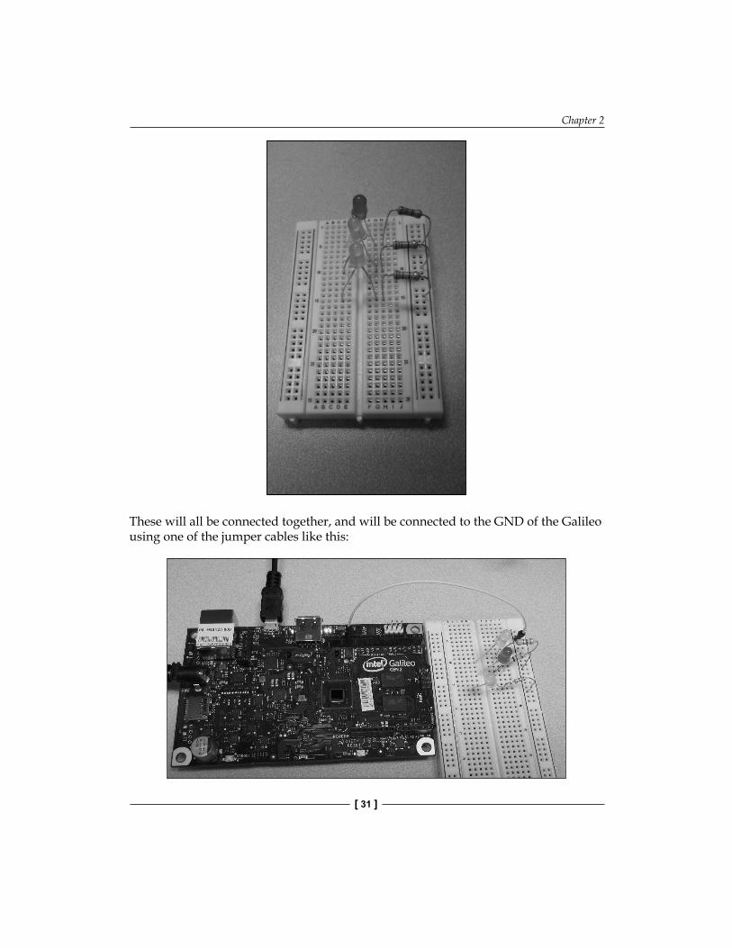
These will all be connected together, and will be connected to the GND of the Galileo using one of the jumper cables like this:
Accessing the GPIO Pins
[ 32 ]
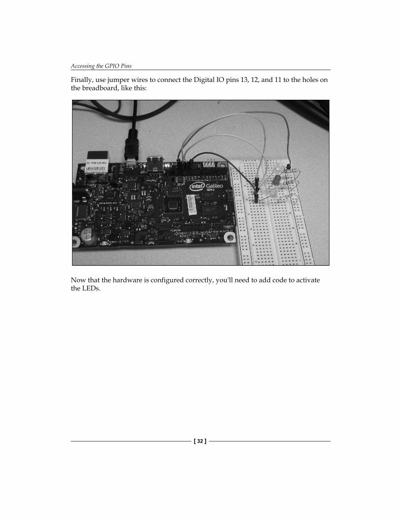
Finally, use jumper wires to connect the Digital IO pins 13, 12, and 11 to the holes on the breadboard, like this:
Now that the hardware is confi gured correctly, you'll need to add code to activate the LEDs.
Chapter 2
[ 33 ]
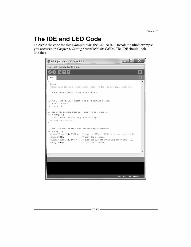
The IDE and LED CodeTo create the code for this example, start the Galileo IDE. Recall the Blink example you accessed in Chapter 1, Getting Started with the Galileo. The IDE should look like this:
Accessing the GPIO Pins
[ 34 ]
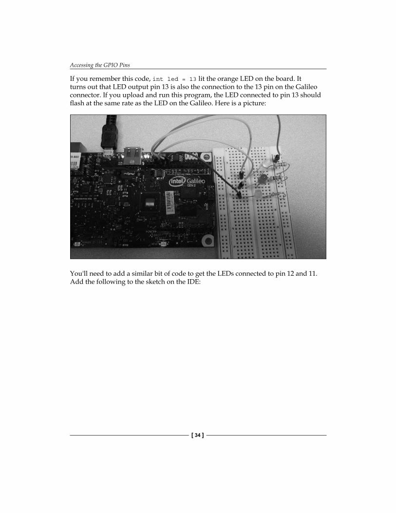
If you remember this code, int led = 13 lit the orange LED on the board. It turns out that LED output pin 13 is also the connection to the 13 pin on the Galileo connector. If you upload and run this program, the LED connected to pin 13 should fl ash at the same rate as the LED on the Galileo. Here is a picture:
You'll need to add a similar bit of code to get the LEDs connected to pin 12 and 11. Add the following to the sketch on the IDE:
Chapter 2
[ 35 ]
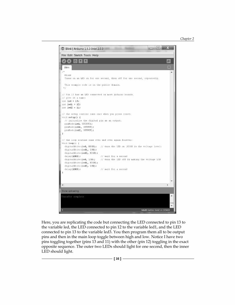
Here, you are replicating the code but connecting the LED connected to pin 13 to the variable led, the LED connected to pin 12 to the variable led1, and the LED connected to pin 13 to the variable led3. You then program them all to be output pins and then in the main loop toggle between high and low. Notice I have two pins toggling together (pins 13 and 11) with the other (pin 12) toggling in the exact opposite sequence. The outer two LEDs should light for one second, then the inner LED should light.
Accessing the GPIO Pins
[ 36 ]
If one or more of the LEDs don't light, check to make sure they are pushed fi rmly down into the board. You can also change the direction of the LED; perhaps you have the leads in the wrong direction on the board.
Getting signals from the outside worldYou know how to send signals to the outside world. You might also want to receive input signals from the outside world. These signals can be divided into two types: digital signals and analog signals.
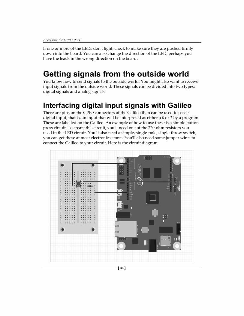
Interfacing digital input signals with GalileoThere are pins on the GPIO connectors of the Galileo than can be used to sense digital input; that is, an input that will be interpreted as either a 0 or 1 by a program. These are labelled on the Galileo. An example of how to use these is a simple button press circuit. To create this circuit, you'll need one of the 220-ohm resistors you used in the LED circuit. You'll also need a simple, single-pole, single-throw switch; you can get these at most electronics stores. You'll also need some jumper wires to connect the Galileo to your circuit. Here is the circuit diagram:
Chapter 2
[ 37 ]
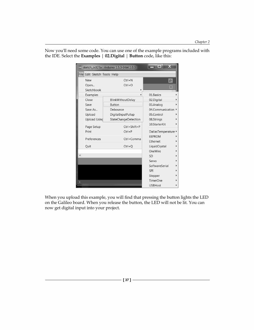
Now you'll need some code. You can use one of the example programs included with the IDE. Select the Examples | 02.Digital | Button code, like this:
When you upload this example, you will fi nd that pressing the button lights the LED on the Galileo board. When you release the button, the LED will not be lit. You can now get digital input into your project.
Accessing the GPIO Pins
[ 38 ]
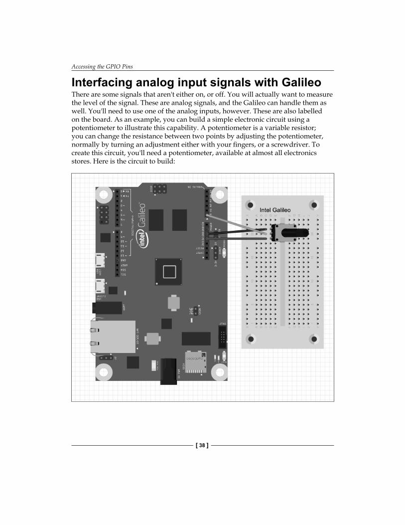
Interfacing analog input signals with GalileoThere are some signals that aren't either on, or off. You will actually want to measure the level of the signal. These are analog signals, and the Galileo can handle them as well. You'll need to use one of the analog inputs, however. These are also labelled on the board. As an example, you can build a simple electronic circuit using a potentiometer to illustrate this capability. A potentiometer is a variable resistor; you can change the resistance between two points by adjusting the potentiometer, normally by turning an adjustment either with your fi ngers, or a screwdriver. To create this circuit, you'll need a potentiometer, available at almost all electronics stores. Here is the circuit to build:
Chapter 2
[ 39 ]
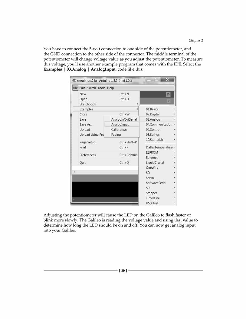
You have to connect the 5-volt connection to one side of the potentiometer, and the GND connection to the other side of the connector. The middle terminal of the potentiometer will change voltage value as you adjust the potentiometer. To measure this voltage, you'll use another example program that comes with the IDE. Select the Examples | 03.Analog | AnalogInput, code like this:
Adjusting the potentiometer will cause the LED on the Galileo to fl ash faster or blink more slowly. The Galileo is reading the voltage value and using that value to determine how long the LED should be on and off. You can now get analog input into your Galileo.
Accessing the GPIO Pins
[ 40 ]
SummaryThat's it. You've completed your very fi rst example of interfacing with the outside world. You can play with different patterns of LED sequences by using loops and different wait states. Now that you have created your very fi rst hardware project, in the next chapter we'll cover how to add hardware capability using a hardware shield, a piece of hardware that plugs directly into the IO connectors of the Galileo.

Where to buy this book You can buy Intel Galileo Essentials from the Packt Publishing website. Alternatively, you can buy the book from Amazon, BN.com, Computer Manuals and most internet book retailers.
Click here for ordering and shipping details.
www.PacktPub.com
Stay Connected:
Get more information Intel Galileo Essentials