Embed Size (px)
Citation preview

Intel® 82574 Family Gigabit Ethernet Controller Specification Update
July 2015Revision 4.0

82574 Specification Update
2
No license (express or implied, by estoppel or otherwise) to any intellectual property rights is granted by this document.Intel disclaims all express and implied warranties, including without limitation, the implied warranties of merchantability, fitness for a particular purpose, and non-infringement, as well as any warranty arising from course of performance, course of dealing, or usage in trade.This document contains information on products, services and/or processes in development. All information provided here is subject to change without notice. Contact your Intel representative to obtain the latest forecast, schedule, specifications and roadmaps.The products and services described may contain defects or errors which may cause deviations from published specifications. Copies of documents which have an order number and are referenced in this document may be obtained by calling 1-800-548-4725 or by visiting www.intel.com/design/literature.htm.Intel and the Intel logo are trademarks of Intel Corporation in the U.S. and/or other countries.*Other names and brands may be claimed as the property of others.© 2015 Intel Corporation.
3
82574 Specification Update
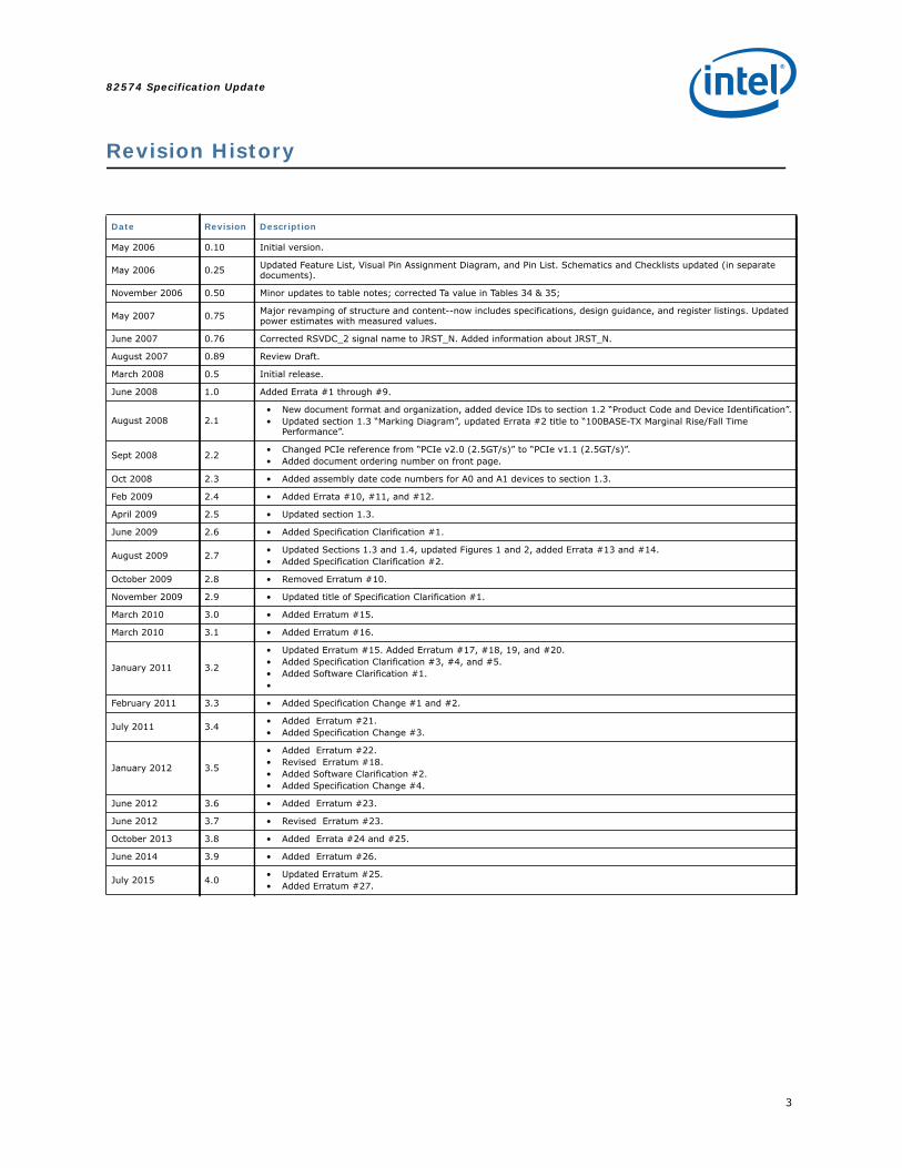
Revision History
Date Revision Description
May 2006 0.10 Initial version.
May 2006 0.25 Updated Feature List, Visual Pin Assignment Diagram, and Pin List. Schematics and Checklists updated (in separate documents).
November 2006 0.50 Minor updates to table notes; corrected Ta value in Tables 34 & 35;
May 2007 0.75 Major revamping of structure and content--now includes specifications, design guidance, and register listings. Updated power estimates with measured values.
June 2007 0.76 Corrected RSVDC_2 signal name to JRST_N. Added information about JRST_N.
August 2007 0.89 Review Draft.
March 2008 0.5 Initial release.
June 2008 1.0 Added Errata #1 through #9.
August 2008 2.1• New document format and organization, added device IDs to section 1.2 “Product Code and Device Identification”.• Updated section 1.3 “Marking Diagram”, updated Errata #2 title to “100BASE-TX Marginal Rise/Fall Time
Performance”.
Sept 2008 2.2 • Changed PCIe reference from “PCIe v2.0 (2.5GT/s)” to “PCIe v1.1 (2.5GT/s)”.• Added document ordering number on front page.
Oct 2008 2.3 • Added assembly date code numbers for A0 and A1 devices to section 1.3.
Feb 2009 2.4 • Added Errata #10, #11, and #12.
April 2009 2.5 • Updated section 1.3.
June 2009 2.6 • Added Specification Clarification #1.
August 2009 2.7 • Updated Sections 1.3 and 1.4, updated Figures 1 and 2, added Errata #13 and #14.• Added Specification Clarification #2.
October 2009 2.8 • Removed Erratum #10.
November 2009 2.9 • Updated title of Specification Clarification #1.
March 2010 3.0 • Added Erratum #15.
March 2010 3.1 • Added Erratum #16.
January 2011 3.2
• Updated Erratum #15. Added Erratum #17, #18, 19, and #20.• Added Specification Clarification #3, #4, and #5.• Added Software Clarification #1.•
February 2011 3.3 • Added Specification Change #1 and #2.
July 2011 3.4 • Added Erratum #21.• Added Specification Change #3.
January 2012 3.5
• Added Erratum #22.• Revised Erratum #18.• Added Software Clarification #2.• Added Specification Change #4.
June 2012 3.6 • Added Erratum #23.
June 2012 3.7 • Revised Erratum #23.
October 2013 3.8 • Added Errata #24 and #25.
June 2014 3.9 • Added Erratum #26.
July 2015 4.0 • Updated Erratum #25.• Added Erratum #27.

82574 Specification Update
4
Note: This page intentionally left blank.
5
82574 Specification Update
1.1 Introduction and Scope
This document applies to the 82574 GbE Ethernet Controller Family.
This document is an update to a published specification, the Intel® 82574 GbE Controller Family Datasheet. It is intended for use by system manufacturers and software developers. All product documents are subject to frequent revision, and new order numbers will apply. New documents may be added. Be sure you have the latest information before finalizing your design.
References to PCIe* in this document refer to PCIe v1.1 (2.5GT/s).
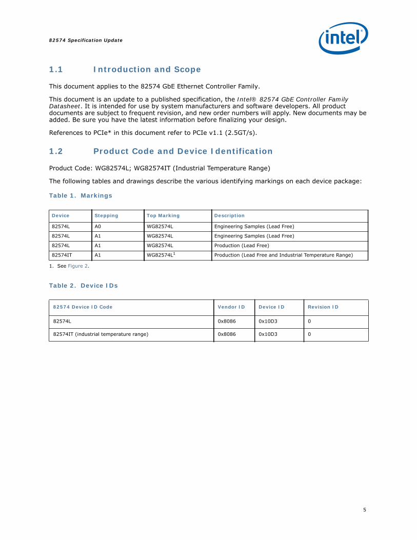
1.2 Product Code and Device Identification
Product Code: WG82574L; WG82574IT (Industrial Temperature Range)
The following tables and drawings describe the various identifying markings on each device package:
Table 1. Markings
Table 2. Device IDs
Device Stepping Top Marking Description
82574L A0 WG82574L Engineering Samples (Lead Free)
82574L A1 WG82574L Engineering Samples (Lead Free)
82574L A1 WG82574L Production (Lead Free)
82574IT A1 WG82574L1
1. See Figure 2.
Production (Lead Free and Industrial Temperature Range)
82574 Device ID Code Vendor ID Device ID Revision ID
82574L 0x8086 0x10D3 0
82574IT (industrial temperature range) 0x8086 0x10D3 0
82574 Specification Update
6
Table 3. MM Numbers
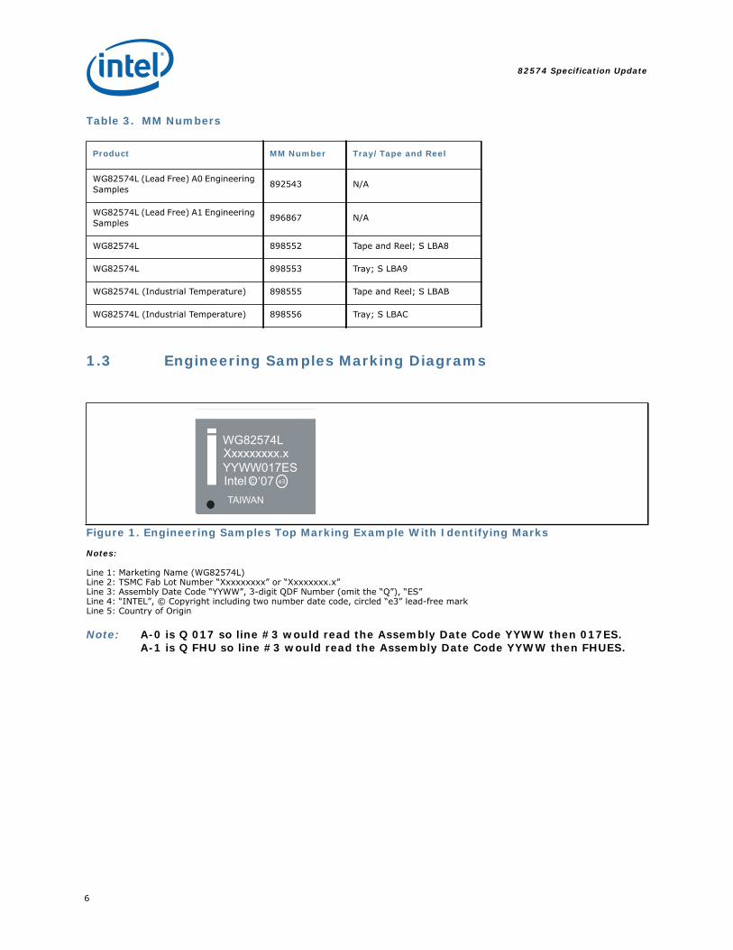
1.3 Engineering Samples Marking Diagrams
Notes:
Line 1: Marketing Name (WG82574L)Line 2: TSMC Fab Lot Number “Xxxxxxxxx” or “Xxxxxxxx.x”Line 3: Assembly Date Code “YYWW”, 3-digit QDF Number (omit the “Q”), “ES”Line 4: “INTEL”, © Copyright including two number date code, circled “e3” lead-free markLine 5: Country of Origin
Note: A-0 is Q 017 so line #3 would read the Assembly Date Code YYWW then 017ES.A-1 is Q FHU so line #3 would read the Assembly Date Code YYWW then FHUES.
Product MM Number Tray/Tape and Reel
WG82574L (Lead Free) A0 Engineering Samples 892543 N/A
WG82574L (Lead Free) A1 Engineering Samples 896867 N/A
WG82574L 898552 Tape and Reel; S LBA8
WG82574L 898553 Tray; S LBA9
WG82574L (Industrial Temperature) 898555 Tape and Reel; S LBAB
WG82574L (Industrial Temperature) 898556 Tray; S LBAC
Figure 1. Engineering Samples Top Marking Example With Identifying Marks
WG82574LXxxxxxxxx.xYYWW017ESIntel C e3‘07TAIWAN
7
82574 Specification Update
1.4 Production Marking Diagrams
Notes:
Line 1: Marketing Name (WG82574L)Line 2: TSMC Fab Lot Number “Xxxxxxxxx” or “Xxxxxxxx.x”Line 3: Assembly Date Code “YYWW”Line 4: “INTEL”, © Copyright including two number date code, circled “e3” lead-free markLine 5: Country of Origin
Note: “I” or “ l” (located under the “e3” lead-free mark) = industrial temperature marking (WG82574IT only)
1.5 Nomenclature Used In This Document
This document uses specific terms, codes, and abbreviations to describe changes, errata and/or clarifications that apply to silicon/steppings. See Table 4 for a description.
Table 4. Terms, Codes, Abbreviations
Figure 2. Production Top Marking Example With Identifying Marks
Name Description
Specification Changes
Modifications to the current published specifications. These changes will be incorporated in the next release of the specifications.
ErrataDesign defects or errors. Errata may cause device behavior to deviate from published specifications. Hardware and software designed to be used with any given stepping must assume that all errata documented for that stepping are present on all devices.
Specification Clarifications
Greater detail or further highlights concerning a specification’s impact to a complex design situation. These clarifications will be incorporated in the next release of the specifications.
Documentation Changes
Typos, errors, or omissions from the current published specifications. These changes will be incorporated in the next release of the specifications.
Yes or NoIf the errata applies to a stepping, “Yes” is indicated for the stepping (for example: “A0=Yes” indicates errata applies to stepping A0). If the errata does not apply to stepping, “No” is indicated (for example: “A0=No” indicates the errata does not apply to stepping A0).
Doc Document change or update that will be implemented.
WG82574LXxxxxxxxx.xYYWWIntel C e3‘07TAIWAN
82574L
82574 Specification Update
8
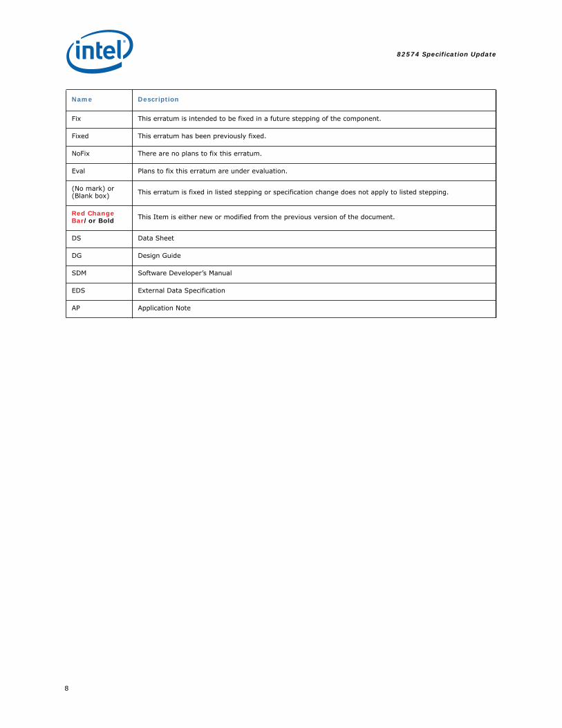
Name Description
Fix This erratum is intended to be fixed in a future stepping of the component.
Fixed This erratum has been previously fixed.
NoFix There are no plans to fix this erratum.
Eval Plans to fix this erratum are under evaluation.
(No mark) or (Blank box) This erratum is fixed in listed stepping or specification change does not apply to listed stepping.
Red Change Bar/or Bold This Item is either new or modified from the previous version of the document.
DS Data Sheet
DG Design Guide
SDM Software Developer’s Manual
EDS External Data Specification
AP Application Note
9
82574 Specification Update
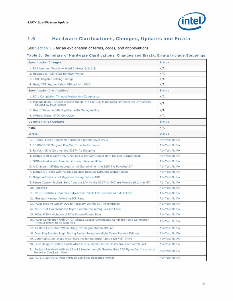
1.6 Hardware Clarifications, Changes, Updates and Errata
See Section 1.5 for an explanation of terms, codes, and abbreviations.
Table 5. Summary of Hardware Clarifications, Changes and Errata; Errata Include Steppings
Specification Changes Status
1. PBA Number Module — Word Address 0x8-0x9 N/A
2. Updates to PXE/iSCSI EEPROM Words N/A
3. TARC Register Setting Change N/A
4. Using TCP Segmentation Offload with IPv6 N/A
Specification Clarifications Status
1. PCIe Completion Timeout Mechanism Compliance N/A
2. Manageability: Critical Session (Keep PHY Link Up) Mode Does Not Block All PHY Resets Caused By PCIe Resets N/A
3. Use of Wake on LAN Together With Manageability N/A
4. SMBus: Illegal STOP Condition N/A
Documentation Updates Status
None. N/A
Errata Status
1. 10BASE-T IEEE-Specified Harmonic Content Level Issue A1=Yes; No Fix
2. 100BASE-TX Marginal Rise/Fall Time Performance A1=Yes; No Fix
3. Revision ID is Zero for the 82574 A1 Stepping A1=Yes; No Fix
4. SMBus Alert is Sent Only Once and is not Sent Again Until the Next Status Read A1=Yes; No Fix
5. SMBus Alert is not Asserted in Direct Receive Mode A1=Yes; No Fix
6. A Change in SMBus Address is not Stored When the 82574 is Powered Off A1=Yes; No Fix
7. SMBus ARP Fails with Multiple Devices Because Different UDIDs Collide A1=Yes; No Fix
8. Illegal Address is not Rejected During SMBus ARP A1=Yes; No Fix
9. Pause Control Packets Sent from the LAN to the 82574’s MAC are Forwarded to the MC A1=Yes; No Fix
10. Removed A1=Yes; No Fix
11. NC-SI Statistics Counters Saturate at 0xFFFFFFFF Instead of 0xFFFFFFFE A1=Yes; No Fix
12. Missing Interrupt Following ICR Read A1=Yes; No Fix
13. PCIe: Missing Replay Due to Recovery During TLP Transmission A1=Yes; No Fix
14. NC-SI Set Link Response Might Contain the Wrong Reason Code A1=Yes; No Fix
15. PCIe: MSI-X Violation of PCIe Posted-Posted Rule A1=Yes; No Fix
16. PCIe: Completion with UR/CA Status Causes Unexpected Completion and Completion Timeout Errors to be Reported A1=Yes; No Fix
17. Tx Data Corruption When Using TCP Segmentation Offload A1=Yes; No Fix
18. Disabling Receive Logic During Packet Reception Might Cause Receive Failures A1=Yes; No Fix
19. Communication Stops After Extreme Temperature Ramp (82574IT Only) A1=Yes; No Fix
20. PCIe Hang or System Crash when L0s is Enabled in the Upstream PCIe Switch Port A1=Yes; No Fix
21. Packets Received With an L2 + L3 Header Length Greater than 256 Bytes Can Incorrectly Report a Checksum Error A1=Yes; No Fix
22. NC-SI: Get NC-SI Pass-through Statistics Response Format A1=Yes; No Fix
82574 Specification Update
10
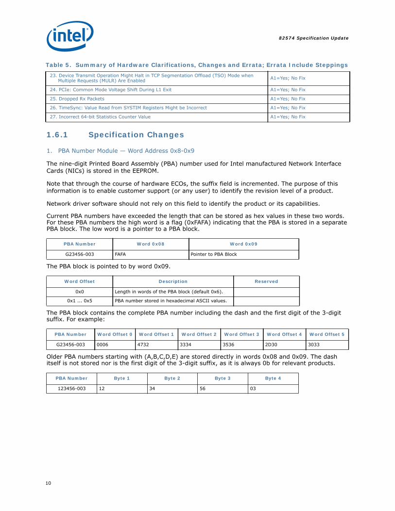
1.6.1 Specification Changes
1. PBA Number Module — Word Address 0x8-0x9
The nine-digit Printed Board Assembly (PBA) number used for Intel manufactured Network Interface Cards (NICs) is stored in the EEPROM.
Note that through the course of hardware ECOs, the suffix field is incremented. The purpose of this information is to enable customer support (or any user) to identify the revision level of a product.
Network driver software should not rely on this field to identify the product or its capabilities.
Current PBA numbers have exceeded the length that can be stored as hex values in these two words. For these PBA numbers the high word is a flag (0xFAFA) indicating that the PBA is stored in a separate PBA block. The low word is a pointer to a PBA block.
The PBA block is pointed to by word 0x09.
The PBA block contains the complete PBA number including the dash and the first digit of the 3-digit suffix. For example:
Older PBA numbers starting with (A,B,C,D,E) are stored directly in words 0x08 and 0x09. The dash itself is not stored nor is the first digit of the 3-digit suffix, as it is always 0b for relevant products.
23. Device Transmit Operation Might Halt in TCP Segmentation Offload (TSO) Mode when Multiple Requests (MULR) Are Enabled A1=Yes; No Fix
24. PCIe: Common Mode Voltage Shift During L1 Exit A1=Yes; No Fix
25. Dropped Rx Packets A1=Yes; No Fix
26. TimeSync: Value Read from SYSTIM Registers Might be Incorrect A1=Yes; No Fix
27. Incorrect 64-bit Statistics Counter Value A1=Yes; No Fix
PBA Number Word 0x08 Word 0x09
G23456-003 FAFA Pointer to PBA Block
Word Offset Description Reserved
0x0 Length in words of the PBA block (default 0x6).
0x1 ... 0x5 PBA number stored in hexadecimal ASCII values.
PBA Number Word Offset 0 Word Offset 1 Word Offset 2 Word Offset 3 Word Offset 4 Word Offset 5
G23456-003 0006 4732 3334 3536 2D30 3033
PBA Number Byte 1 Byte 2 Byte 3 Byte 4
123456-003 12 34 56 03
Table 5. Summary of Hardware Clarifications, Changes and Errata; Errata Include Steppings
11
82574 Specification Update
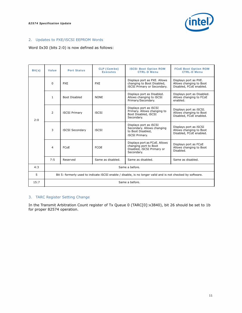
2. Updates to PXE/iSCSI EEPROM Words
Word 0x30 (bits 2:0) is now defined as follows:
3. TARC Register Setting Change
In the Transmit Arbitration Count register of Tx Queue 0 (TARC[0]:x3840), bit 26 should be set to 1b for proper 82574 operation.
Bit(s) Value Port Status CLP (Combo) Executes
iSCSI Boot Option ROM CTRL-D Menu
FCoE Boot Option ROM CTRL-D Menu
2:0
0 PXE PXEDisplays port as PXE. Allows changing to Boot Disabled, iSCSI Primary or Secondary.
Displays port as PXE. Allows changing to Boot Disabled, FCoE enabled.
1 Boot Disabled NONEDisplays port as Disabled. Allows changing to iSCSI Primary/Secondary.
Displays port as Disabled. Allows changing to FCoE enabled.
2 iSCSI Primary iSCSI
Displays port as iSCSI Primary. Allows changing to Boot Disabled, iSCSI Secondary.
Displays port as iSCSI. Allows changing to Boot Disabled, FCoE enabled.
3 iSCSI Secondary iSCSI
Displays port as iSCSI Secondary. Allows changing to Boot Disabled,iSCSI Primary.
Displays port as iSCSI Allows changing to Boot Disabled, FCoE enabled.
4 FCoE FCOE
Displays port as FCoE. Allows changing port to Boot Disabled, iSCSI Primary or Secondary.
Displays port as FCoE Allows changing to Boot Disabled.
7:5 Reserved Same as disabled. Same as disabled. Same as disabled.
4:3 Same a before.
5 Bit 5: formerly used to indicate iSCSI enable / disable, is no longer valid and is not checked by software.
15:7 Same a before.

82574 Specification Update
12
4. Using TCP Segmentation Offload with IPv6
When using TCP segmentation offload of IPv6 packets with two transmit queues, the following settings must be used:
• Program IPCSO equal to TUCSO in the context descriptor.• Set IXSM in addition to TXSM in the data descriptor(s).
The Intel Windows* driver implements this change in Release 16.7.
The Intel Linux driver (e1000e) only uses one transmit queue.

13
82574 Specification Update
1.6.2 Specification Clarifications
1. PCIe Completion Timeout Mechanism Compliance
If the latency for PCIe completions in a system is above 21 ms and PCIe completion timeout mechanism is enabled, there may be unpredictable system behavior.
The 82574 complies with the PCIe 1.1 specification for completion timeout mechanism. The PCIe 1.1 specification provides a timeout range between 50 μs to 50 ms with a strong recommendation that it be at least 10 ms. The 82574 uses a range of 21-42 ms.
The completion timeout value in a system MUST be above the expected maximum latency for completions in the system in which the 82574 is installed. This will ensure that the 82574 receives the completions for the requests it sends out, avoiding a completion timeout scenario. If the latency for completions is above 21 ms this can result in the device timing out prior to a completion returning. In the event of a completion timeout, per direction in the PCIe specification the device assumes the original completion is lost, and resends the original request. In this condition, if the completion for the original request arrives at the 82574 devices, this will result in two completions arriving for the same request, which may cause unpredictable system behavior.
Therefore, if the PCIe completion latency for a system cannot be guaranteed to be lower than 21 ms, the PCIe completion timeout mechanism should be disabled by setting GCR.Disable_timeout_mechanism.
For more details on Completion Timeout operation in the 82574 refer to the Intel® 82574 GbE Controller Family Datasheet.
2. Manageability: Critical Session (Keep PHY Link Up) Mode Does Not Block All PHY Resets Caused By PCIe Resets
Problem: D3 to D0 transition causes a PHY reset in Keep PHY Link Up mode. When Critical Session Mode (Keep PHY Link Up) is enabled (via the NC-SI Set Intel Management Control command or the SMBus Management Control command), PCIe resets should not cause a PHY reset. However, the following event still causes a PHY reset.
Transition from D3 to D0 without a general PCI reset. For example, PMCSR[1:0] is changed from 11b to 00b by a configuration write.
Implication: Loss of link can cause a loss of the manageability session. These events do not normally occur during a reboot cycle, so it is expected that no effect will be seen in most circumstances.
Workaround: None
3. Use of Wake on LAN Together With Manageability
The Wakeup Filter Control Register (WUFC) contains the NoTCO bit, which affects the behavior of the wakeup functionality when manageability is in use. Note that if manageability is not enabled, the value of NoTCO has no effect.
When NoTCO contains the hardware default value of 0b, any received packet that matches the wakeup filters will wake the system. This could cause unintended wakeups in certain situations. For example, if Directed Exact Wakeup is used and the manageability shares the host's MAC address, IPMI packets that are intended for the BMC wakes the system, which might not be the intended behavior.
When NoTCO is set to 1b, any packet that passes the manageability filter, even if it also is copied to the host, is excluded from the wakeup logic. This solves the previous problem since IPMI packets do not wake the system. However, with NoTCO=1b, broadcast packets, including broadcast magic packets, do not wake the system since they pass the manageability filters and are therefore excluded.
82574 Specification Update
14
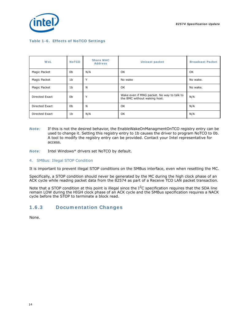
Table 1-6. Effects of NoTCO Settings
Note: If this is not the desired behavior, the EnableWakeOnManagmentOnTCO registry entry can be used to change it. Setting this registry entry to 1b causes the driver to program NoTCO to 0b. A tool to modify the registry entry can be provided. Contact your Intel representative for access.
Note: Intel Windows* drivers set NoTCO by default.
4. SMBus: Illegal STOP Condition
It is important to prevent illegal STOP conditions on the SMBus interface, even when resetting the MC.
Specifically, a STOP condition should never be generated by the MC during the high clock phase of an ACK cycle while reading packet data from the 82574 as part of a Receive TCO LAN packet transaction.
Note that a STOP condition at this point is illegal since the I2C specification requires that the SDA line remain LOW during the HIGH clock phase of an ACK cycle and the SMBus specification requires a NACK cycle before the STOP to terminate a block read.
1.6.3 Documentation Changes
None.
WoL NoTCO Share MAC Address Unicast packet Broadcast Packet
Magic Packet 0b N/A OK OK
Magic Packet 1b Y No wake No wake.
Magic Packet 1b N OK No wake.
Directed Exact 0b Y Wake even if MNG packet. No way to talk to the BMC without waking host. N/A
Directed Exact 0b N OK N/A
Directed Exact 1b N/A OK N/A
15
82574 Specification Update
1.6.4 Errata
1. 10BASE-T IEEE-Specified Harmonic Content Level Issue
Problem: On some board designs, the 82574 might not meet the IEEE specification (1411.10.03) that states that the harmonic content is to be at least 27 dB below the 10 MHz fundamental frequency.
Implication: IEEE conformance is marginal. There is no impact on system level performance; however, care should be taken to verify the impact of radiated EMI (Electromagnetic Interference) on system-level EMI tests.
Workaround: There is no silicon/firmware/software workaround; however, using short low-resistance traces (less than four inches and without a LAN switch) can help reduce harmonic content.
Status: A1=Yes; No Fix
2. 100BASE-TX Marginal Rise/Fall Time Performance
Problem: The 82574 rise/fall time has been marginal compared to the IEEE specification (5 ns).
Implication: IEEE conformance is marginal. Depending on system topology (LAN switch/no LAN switch), MDI trace lengths, and configuration (docked/undocked), the 100BASE-TX rise/fall time might not meet the IEEE specification. Note that there is no impact on system level performance.
Workaround: There is no silicon/firmware/software workaround. However, using short low-resistance traces (less than four inches and without a LAN switch) can help improve rise time. In some designs it’s better to use two 82574’s instead of a LAN switch.
Status: A1=Yes; No Fix
3. Revision ID is Zero for the 82574 A1 Stepping
Problem: The Revision ID field in the PCIe configuration space is zero instead of one.
Implication: Error counters may not be accurate.
Workaround: None.
Status: A1=Yes; No Fix
4. SMBus Alert is Sent Only Once and is not Sent Again Until the Next Status Read
Problem: The 82574 does not notify the Manageability Controller (MC) for changes until a status read occurs.
Implication: If one notification is missed then no notification is sent to the MC.
Workaround: The MC should periodically poll for status.
Status: A1=Yes; No Fix
82574 Specification Update
16
5. SMBus Alert is not Asserted in Direct Receive Mode
Problem: SMBus alert is disabled while in direct receive mode. As a result, the 82574 does not notify the MC for any change that occurs.
Implication: The MC is not notified of any changes due to no interrupt mechanism for direct receive mode.
Workaround: Although not recommended, the MC needs to poll for status.
Status: A1=Yes; No Fix
6. A Change in SMBus Address is not Stored When the 82574 is Powered Off
Problem: As a PSA device, the 82574 must maintain its assigned address through a power loss. The 82574’s current implementation returns to its original SMBus address.
Implication: The 82574 is unable to maintain its assigned address after a power loss.
Workaround: Disable SMBus ARP and then use the unique SMBus address in the 82574’s NVM. Note that the recommended practice for this SMBus link between the MC and the 82574 is to be dedicated – no other devices should be on this SMBus.
Status: A1=Yes; No Fix
7. SMBus ARP Fails with Multiple Devices Because Different UDIDs Collide
Problem: SMBus ARP fails with multiple devices. As a result, the 82574 is unable to change SMBus addresses.
Implication: The 82574 cannot effectively support SMBus ARP with multiple devices.
Workaround: Disable SMBus ARP and then store a unique SMBus address in the 82574’s NVM. Note that the SMBus ARP link is dedicated between the BMC, MC, and the 82574 as well as being the recommended configuration.
Status: A1=Yes; No Fix
17
82574 Specification Update
8. Illegal Address is not Rejected During SMBus ARP
Problem: Direct SMBus commands that should fail don't during the SMBus ARP process. As a result, illegal addresses aren't rejected during SMBus ARP.
Implication: The 82574 does not fully support SMBus ARP protocol.
Workaround: Disable SMBus ARP and then use the unique SMBus address in the 82574’s NVM. Note that the recommended practice for this SMBus link between the MC and the 82574 is to be dedicated – no other devices should be on this SMBus.
Status: A1=Yes; No Fix
9. Pause Control Packets Sent from the LAN to the 82574’s MAC are Forwarded to the MC
Problem: The 82574 passes MAC control frames to the MC. As a result, the 82574 causes the MC MAC to pause its transmission.
Implication: NC-SI flow control is not supported in the 82574.
Workaround: The MC must disable its flow control functionality.
Status: A1=Yes; No Fix
10. Removed
11. NC-SI Statistics Counters Saturate at 0xFFFFFFFF Instead of 0xFFFFFFFE
Problem: The Get NC-SI Statistics Response uses 0xFFFFFFFF as a reserved value to indicate unsupported counters. The statistics counters should therefore either stop or wraparound at 0xFFFFFFFE. The 82574 counters stop at 0xFFFFFFFF.
Implication: Any statistics counter that has saturated is reported as not implemented.
Workaround: The Manageability Controller (MC) should read the counters often enough to prevent them from reaching their maximum value. Even assuming 64-byte packets arriving from the LAN at 1 Gb/s, the dropped packet counter does not saturate in less than half an hour.
Status: A1=Yes; No Fix
82574 Specification Update
18
12. Missing Interrupt Following ICR Read
Problem: If the Interrupt Cause Register (ICR) is read when at least one bit is set in the interrupt mask register and INT_ASSERTED is set to 0b, a new interrupt event occurring on the same clock cycle as the ICR read is ignored.
Implication: Missed interrupts leading to delays in responding to interrupt events. Specifically, this can cause a delay in processing a received packet.
Typically, the ICR is only read in response to an interrupt so this problem does not occur. However, when using legacy interrupts and sharing interrupts between devices, software might poll all the devices to find the source of the interrupt, including those devices that did not assert an interrupt. There might also be other situations in non-Intel drivers where ICR is polled even when no interrupt has been asserted.
Workaround: If reading ICR when there is no active interrupt cannot be avoided, clear the mask register (by writing 0xFFFFFFFF to IMC) before reading ICR. Note that in this case the ICR is cleared when read even if INT_ASSERTED is set 0b.
Status: A1=Yes; No Fix
13. PCIe: Missing Replay Due to Recovery During TLP Transmission
Problem: If the replay timer expires during the transmission of a TLP and the LTSSM moves from L0 to recovery during the transmission of the same TLP, the expected replay does not occur. Additionally, the replay timer is disabled, so no further replays occur unless a NAK is received.
Implication: This situation should not occur during normal operation. If it does occur while the upstream switch is waiting for a replay, the result would be a Surprise Down error which might halt the system.
Workaround: None.
Status: A1=Yes; No Fix
14. NC-SI Set Link Response Might Contain the Wrong Reason Code
Problem: When a Set Link Command attempts to force more than one speed at the same time, the Set Link Speed Conflict value (0x5) should be provided as the Reason Code in the response. The 82574 provides a Reason Code of Set Link Media Conflict (0x2) instead.
Implication: Non-conformance to NC-SI spec recommendation. No functional impact.
Workaround: Treat the 0x2 Reason Code value in the Set Link Response as indicating a general problem with the Set Link Command parameters.
Status: A1=Yes; No Fix
19
82574 Specification Update
15. PCIe: MSI-X Violation of PCIe Posted-Posted Rule
Problem: According to the PCIe Specification, "the acceptance of a Posted Request must not depend upon the transmission of any TLP from that same Upstream Port within the same traffic class" The 82574 has a dependency between downstream posted requests to its MSI-X table and upstream MSI-X packets (MSI-X interrupt messages) that violates this rule.
Implication: Under specific stress scenarios, the upstream device might stop providing posted credits to the 82574. If the 82574 has a MSI-X message to send out and it runs out of posted credits, any upstream device access to the 82574 MSI-X table (read/write) does not complete until credits are renewed. Under this condition, the 82574 stops releasing posted credits to the upstream device, and posted data transfer stops in both directions resulting in a link deadlock. If the upstream device is able to renew its credit release flow, the 82574 is not susceptible to this erratum.
Workaround: Use MSI instead of MSI-X interrupts. This can be accomplished via registry edits in the Windows* OS. Intel can provide a tool that will automatically make the required registry edits. For Linux* this can be accomplished with added parameters at driver load by modifying IntMode in /etc/modprobe.conf. IntMode=0 means set port 0 to the legacy interrupt (1 is for MSI, and 2 is for MSI-X). Full details can be found in Linux driver README.
Contact your Intel representative for additional details or to obtain a tool for Windows drivers.
Status: A1=Yes; No Fix
82574 Specification Update
20
16. PCIe: Completion with UR/CA Status Causes Unexpected Completion and Completion Timeout Errors to be Reported
Problem: When the 82574 receives a PCIe completion with Unsupported Request (UR) or Completer Abort (CA) status in response to a request it generated, it reports an Unexpected Completion error. Because the completion timer is not disabled, a completion timeout error is reported when the timer expires.
Implication: This situation should not occur in systems that are operating correctly since all requests generated by the 82574 are supported.
If an UR/CA completion is received, the completion timeout error can bring down the operating system when it is reported.
Workaround: Not required for systems that are operating correctly.
Note that reporting completion timeout errors can be masked in the Uncorrectable Error Mask register.
Status: A1=Yes; No Fix
17. Tx Data Corruption When Using TCP Segmentation Offload
Problem: When using TSO, a situation can occur where a PCIe MRd request is repeated with the same address, resulting in data corruption. At the end of the TCP packet, the Tx DMA hangs because the length doesn't match. This can only occur when the following are true:
• The first buffer of the packet is larger than [3 * (max_read_request - 4)].• There is a 4 KB boundary within 64 bytes following the end of the header bytes in
the buffer
Implication: Possible data corruption since a TCP packet is transmitted containing the wrong data but with the correct checksum.
Data transmission halts as the Tx DMA module enters a hang state.
Workaround: The failure can be avoided by ensuring at least one of the following:• The buffer containing the headers should not be larger than [3 *
(max_read_request - 4)]. To meet this requirement even for the minimum value of 128 bytes for max_read_request, the buffer should not be larger than 372 bytes.
• The alignment of the buffer containing the headers should be such that there is no 4 KB boundary within 64 bytes following the end of the header bytes. Assuming standard Ethernet/IP/TCP headers of 54 bytes, this means that the buffer should not start 54-118 bytes before a 4 KB boundary. For example, 128-byte alignment for this buffer could be used to fulfill this condition.
This problem has not been reported when using an Intel Linux* or Windows* drivers. Current analysis shows it is very unlikely for a situation to exist that would cause the 82574 to be at risk for the errata when using the Intel Linux or Windows drivers.
Status: A1=Yes; No Fix

21
82574 Specification Update
18. Disabling Receive Logic During Packet Reception Might Cause Receive Failures
Problem: Clearing the RCTL.EN bit while a packet is being received might cause a failure of the receive packet buffer pointer mechanism.
Implication: Unpredictable behavior and/or hang of receive packet buffer control logic.
When using Intel drivers, this situation might occur when updating the receive address filters. For example, when establishing or tearing down multicast connections. To help minimize seeing this issue, limit the number and frequency of multicast addresses.
Workaround: Use one of the following options:• Do not clear RCTL.EN. Operations are halted by using CTRL.RST and then re-
initializing the device.
-OR-• In order to disable receive operation, all receive filters should first be disabled such
that no packets are stored in the packet buffer. All of the following must be true before clearing RCTL.EN.
• RCTL.UPE, RCTL.MPE, RCTL.VFE, RCTL.PMCF, and RCTL.BAM are 0b.• RCTL.DPF is 1b.• The Address Valid bit is 0b in all 16 RAH registers.• The Multicast Table Array is clear.
Once RCTL.EN has been cleared, the register values can be restored to the normal values.
Note: This option should not be used if manageability is enabled since the MC might direct packets to the host despite all of the previous settings.
-OR-
In order to disable receive operation, the PHY should be held in reset such that no packets are stored in the packet buffer. Use the following sequence:
• Set CTRL.PHY_RST.• Clear RCTL.EN.• Clear CTRL.PHY_RST.
Note: This option should not be used if there is a critical manageability session in progress. For example, if the MANC.KEEP_PHY_LINK_UP bit is 1b.
Intel drivers implemented the workaround starting from Release 16.4 (Linux e1000e v1.4.4).
Status: A1=Yes; No Fix
82574 Specification Update
22
19. Communication Stops After Extreme Temperature Ramp (82574IT Only)
Problem: Some 82574IT components intermittently stop Ethernet link communication after extreme increasing temperature ramps (starting at less than -20 °C and ramping up to 85 °C). The problem has been observed only when the 82574IT is initially reset at low temperature and then temperature is increased. The problem is only observed once for each time the part is reset at low temperature. After the driver resets the 82574IT, the problem is not seen again.
Implication: This could cause a loss of Ethernet link communication.
Workaround: Release 13.5 or later (Windows*) or Release 15.5 or later (Linux*) there will be a detection of the error and a driver reset that recovers link after approximately 2 to 5 seconds.
For those developers creating their own driver, the following workaround can be put into a check for hang routine that is called by the driver every second:
1. Read the standard PHY receive ERROR counter (address: 21d).
2. If the recieve error counter equals 0xFFFF then proceed to reading the 1000BASE-T status register (address: 10d).
a. If the Idle Error Count (bits 7:0) reported through this register equals 0xFF then the PHY is hung.
3. If the PHY hung condition is detected twice in two consecutive calls to the check for hang routine the device should be reset and completely re-initialized by the driver.
Status: A1=Yes; No Fix
20. PCIe Hang or System Crash when L0s is Enabled in the Upstream PCIe Switch Port
Problem: When the 82574’s PCIe receive lane goes in and out of the L0s state, there might be failures in the PCIe logic that result in a PCIe hang or a PCIe uncorrectable error. These issues have been reported when the 82574 is connected to the Intel® 5 Series Express Chipset ports, but they do not occur on all PCIe switch ports.
Problematic connections to the 82574 can be identified by clearing and polling the Correctable Error Status register in the PCIe config space on the 82574 while passing LAN traffic. Repeated assertions of the Bad DLLP and/or Replay Timer Timeout bits more than once per minute indicate a problematic situation in which the following workaround should be applied.
Implication: Either a PCIe hang that requires a PCIe reset assertion to recover, or a system crash due to an uncorrectable error reported by the 82574.
Workaround: Disable L0s in the Intel® 5 Series Express Chipset port connected to the 82574. Note there is no requirement to disable ASPM-L1.
Status: A1=Yes; No Fix
23
82574 Specification Update
21. Packets Received With an L2 + L3 Header Length Greater than 256 Bytes Can Incorrectly Report a Checksum Error
Problem: L2/L3 packets with long/multiple next header extensions incorrectly report a receive checksum error when the length from a Destination Address (DA) to the beginning of the TCP/UDP header is greater than 256 bytes.
Implication: A receive checksum error can incorrectly be reported by the 82574, even if there is no checksum error.
Workaround: When the driver receives a packet with a checksum error reported by hardware, software should check the L2/L3 header length. If the L2/L3 header length is 256 bytes or greater, software should verify the checksum.
The Intel Windows and Linux drivers address this issue by passing packets with bad checksums to the network stack for further examination.
Status: A1=Yes; No Fix
82574 Specification Update
24
22. NC-SI: Get NC-SI Pass-through Statistics Response Format
Problem: The NC-SI specification, version 1.0.0a defines the pass-through Tx packets counter contained in the Get NC-SI Pass-through Statistics Response Packet to be an 8-byte field. The 82574 provides this counter as a 4-byte field.
Implication: A BMC that uses the Get NC-SI Pass-through Statistics command and expects the response format as described in the NC-SI specification will not parse the response as intended by the 82574, and will obtain inaccurate statistics.
Workaround: The BMC can account for the different format provided by the 82574 and parse the response accordingly.
Status: A1=Yes; No Fix
23. Device Transmit Operation Might Halt in TCP Segmentation Offload (TSO) Mode when Multiple Requests (MULR) Are Enabled
Problem: The Device Transmit flow stops and the device hangs when operating in TSO with MULR enabled.
Implication: When operating in TCP Segmentation Offload mode and with Multiple Request enabled, the workaround listed below must be in place, or the Transmit Flow may stop unexpectedly.
Workaround: The driver must ensure that the first descriptor points to the (L2+L3+L4) Header and at least two bytes of the data (payload). This has been implemented in the Intel Windows drivers in Release 16.4. Linux (e1000e) has had this workaround implemented since the 82574 has been supported in the driver.
Status: A1=Yes; No Fix
24. PCIe: Common Mode Voltage Shift During L1 Exit
Problem: When using the PCIe ASPM L1 state, there might be a shift in the common mode voltage on the 82574 PCIe Tx lines when exiting the L1 state. This shift only occurs if the 82574 initiates the L1 exit and does not occur if the upstream device initiates the L1 exit.
Implication: In rare cases, the voltage shift on the 82574 PCIe Tx lines can cause the upstream device's receiver to incorrectly detect some bit values at a later time as it responds to the voltage shift. This could cause a failure to exit the L1 state and a surprise down error on the PCIe link.
Workaround: Either disable ASPM L1 or set bit 10 of word 0x1E in the NVM.
Note: This NVM change was implemented in NVM release 2.1.4.
Status: A1=Yes; No Fix
25
82574 Specification Update
25. Dropped Rx Packets
Problem: When receiving a mixture of Ethernet packets, some of which should pass the L2 address filtering and some of which should not, a few of the packets that should pass are actually dropped. The rate of dropped packets might vary, but it is on the order of 1 in 30,000 with random traffic.
Implication: A small number of missing Rx packets. On TCP connections, this might not be noticeable. On UDP connections, the application layer might be affected.
Workaround: Do one of the following:• Set NVM word 0x0F, bit 1. This is the preferred workaround since it does not
significantly increase the power consumption when the 82574 is idle. This workaround is implemented in the 82574 Dev_Starter NVM v2.1.4. Contact your Intel representative to obtain updated NVM images.
• Clear GCR.L1_act_without_L0s_rx and disable ASPM L0s. These settings have the side effect of preventing the 82574 from entering the ASPM L1 state, thereby eliminating the power savings when the 82574 is idle.
Status: A1=Yes; No Fix
26. TimeSync: Value Read from SYSTIM Registers Might be Incorrect
Problem: Due to a synchronization error, the value read from SYSTIML/SYSTIMH might be incorrect. The probability of failure depends on several factors, but it is always less than 50%.
Implication: It is problematic to use the SYSTIM clock as a system clock because the read values are unreliable.
Workaround: Do one of the following:
To get a reliable value, read the SYSTIM registers twice and check that both of the following are true:
• The difference between the 2 values is a multiple of TIMINCA.inc_value..• The difference between the 2 values is positive and the magnitude is reasonable for
consecutive reads on the system. For example, 100 μs might be a good threshold.
If either of these conditions is false, discard the value and try again.
The Intel e1000e driver included this workaround starting with v3.0.4.
Status: A1=Yes; No Fix
27. Incorrect 64-bit Statistics Counter Value
Problem: As documented in the datasheet, the 64-bit statistics counters are cleared when reading the upper 32-bit register. As a result, any increments to the counter that occurred between reading the lower 32-bit register and reading the upper 32-bit register are lost.
This applies to the following statistics counters:
Good Octets Received
Good Octets Transmitted
Total Octets Received
Total Octets Transmitted
82574 Specification Update
26
Implication: The counter values could be slightly lower than the actual number of octets received or transmitted.
Workaround: To minimize the probability of this issue occurring, read the counters as infrequently as possible. (At 1 Gb/s, the octet counters cannot saturate in less than 4675 years.) Also, ensure that the upper 32-bit register is read as soon as possible after reading the lower 32-bit register.
To prevent any loss of information, ignore the upper 32-bit register and treat the lower 32-bit register as a 32-bit counter that is not cleared by read and wraps to zero when it reaches its maximum value. Read this counter at least once every 30 seconds, and maintain the high portion of the counter in software by incrementing it each time the hardware counter value has wrapped since the previous read.
Status: A1=Yes; No Fix
27
82574 Specification Update
2. Software Clarifications
1. While in TCP Segmentation Offload, Each Buffer is Limited to 64 KB
Problem Description:
The 82574 supports 256 KB TCP packets; however, each buffer is limited to 64 KB since the data length field in the transmit descriptor is only 16 bits. This restriction increases driver implementation complexity if the operating system passes down a scatter/gather element greater than 64 KB in length. This can be avoided by limiting the offload size to 64 KB.
Investigation has concluded that the increase in data transfer size does not provide any noticeable improvements in LAN performance. As a result, Intel network software drivers limit the data transfer size in all drivers to 64 KB.
Please note that Linux operating systems only support 64 KB data transfers.
For further details about how Intel network software drivers address this issue, refer to Technical Advisory TA-191.
2. Serial Interfaces Programmed by Bit Banging
Problem Description:
When bit banging on a serial interface (such as SPI, I2C, or MDIO), it is often necessary to perform consecutive register writes with a minimum delay between them. However, simply inserting a software delay between the writes can be unreliable due to hardware delays on the CPU and PCIe interfaces. The delay at the final hardware interface might be less than intended if the first write is delayed by hardware more than the section write. To prevent such problems, a register read should be inserted between the first register write and the software delay. For example: write, read, software delay, write.
Table 2-1. Summary or Software Clarifications
Software Clarifications Status
1. While in TCP Segmentation Offload, Each Buffer is Limited to 64 KB N/A
2. Serial Interfaces Programmed by Bit Banging N/A

82574 Specification Update
28
NOTE: This page intentionally left blank.


![[PPT]Fast Ethernet and Gigabit Ethernet - WPIweb.cs.wpi.edu/~rek/Undergrad_Nets/B04/Fast_Ethernet.ppt · Web viewFast Ethernet and Gigabit Ethernet Fast Ethernet (100BASE-T) How to](https://img.pdfslide.us/doc/110x75/5b29d4a97f8b9aad2f8b4e9d/pptfast-ethernet-and-gigabit-ethernet-rekundergradnetsb04fastethernetppt.jpg)