Embed Size (px)
Citation preview

INTEGRITY TESTING OF BRUSH SEAL IN A T-700 ENGINE
Robert C. Hendricks, Thomas A. Griffin, George A. Bobula, and Robert C. Bill
National Aeronautics and Space AdministrationLewis Research Center
Cleveland, Ohio, 44135
Harold W. Howe
Technetics CorporationDeland, Florida
SUMMARY
A split-ringbrushsealwas fabricated,installedbetweentwo labyrinth-honeycombshroudseals,andtestedinthefourth-stageturbineofa T-700 engine.The annealedHaynes 25 bristlesrubbeddirectlyagainstthenonconditioned,irregularRend 80 turbinebladeshroudsurface.A totalof21 hr ofcyclicand
steady-statedatawere takenwithsurfacespeedsto335 m/s (II00ft/s)and shroudtemperaturesto620 °C(1150*F). Wear appearedtobe rapidinitially,withan orangeflashofhotbrushfragmentsduringthefirstenginestartup,to minimalafter10 hr ofoperation.The brushsurvivedthetestingbut experiencedsome
bristlepulloutsand severebristlewear;some turbineinterfacewear and possiblematerialtransferwasnoted. Futuredesignconcernscenteron tribologicalbehaviorat theinterfacewithorwithoutlubricants.
INTRODUCTION
Enginetestingofbrushsealshasbeenreported(e.g.,RollsRoyce (ref.1)and Allison(ref.2))thatdemonstratedperformanceincreasesrelativetolabyrinthseals.These brushsealsystemshad smoothrotorinterfaces(<25 rms) and operatedat moderatetemperaturesand surfacespeeds.Even thoughthesetestswere successful,concernovercatastrophicfailureofthebrush,suchas a lossofbristleswhensubjectedto highsurfacespeedsat elevatedtemperatures,has not beenresolved.
The objectivesofthisprogram werefirsttodemonstratethata well-designedand manufactured
brushsealcouldsurvivethe "pounding"ofan irregularrotorsurfacewithoutcatastrophicfailure,secondto illustratetheconceptofrunninga combinedbrushand labyrinthsealsystem,and thirdtoacquiremetallographicdata on bristlessubjectedtosuchan environment.
EXPERIMENTAL BRUSH CONFIGURATION AND INSTALLATION
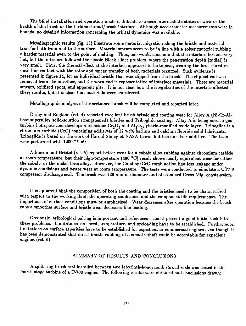
A cross-sectionalviewofthesplit-ringbrushsealconfigurationisillustratedinfigure1. A majorproblemindesigningretrofitsealsisconsistencyofhardwaremeasurements,and forthisexperimentalenginethesealwas craftedtofit.
InordertofitintotheexistingT-700enginefourth-stageturbineshroud,thedesignwas requiredto
fitintoa radialclearanceabouthalfthatnormallyusedforbrushseals.The 0.071-mm (0.0028-in.)diameter,Haynes 25 bristleswere angled43° to 50° to theinterfacewithabout2500 perinchofcircum-ference(98.4permillimeterofcircumference)."Thebackingwasher(orfence)was angled19° tomatchtheslopeoftheturbineshroud.The designclearancewas -0.51 mm (-0.02in.)but couldrangeto
-1.27mm (-0.05in.)diametral(theuncertaintyreflectingthatoftheenginegeometry)withan outsidediameter of 333.9 mm (13.146 in.) and an inside diameter of 322.3 mm (12.690 in.).
117
https://ntrs.nasa.gov/search.jsp?R=19940017319 2018-05-26T21:50:21+00:00Z

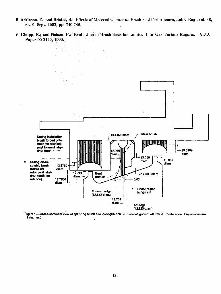
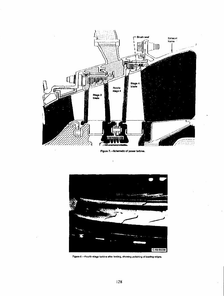
Figure 2 shows several views of the split-ring brush seal, illustrating the joint and the restraining pinhole. Figure 3 shows the unusual brush cross section that was crafted to fit the turbine shroud between
the two labyrinth-honeycomb seals. Figure 4 shows a closeup view of the installed brush; and figure 5, anoverall view of the installed brush. Figure 6(a) shows the pressure tap locations in one of the shrouds. A
thermocouple was installed in each shroud (fig. 6(b)); three of the four were functional. Figures 6(c) and(d) show views of the shroud ring and instrumentation lines.
Assembly of the turbine with the shroud required forcing the brush past the upstream labyrinthtooth without any visual or instrumented guidelines; see figure 7 (power turbine). Forcing the brush overthe labyrinth tooth spread the bristles axially into the upstream direction. This type of spreading altersthe bristle packing configuration, but the extent of alteration and the degree of spreading are unknown.
Post-test results indicated that perhaps two to three upstream bristle rows remained spread with possiblyone downstream bristle row in disarray. Still the brush was resilient because the remaining rows
appeared to be in position. The flexibility of a brush seal and the abuse it can withstand appear to besignificant.
With the brush installed, the turbine shaft was difficult to rotate, requiring 14.7 N-m (130 in.-lbf) oftorque. This was a major concern because heat generation could be sufficient to melt the materials at theinterface. The geared tooth rotor results (ref. 3), including material smearing, cutting, and local hotspots, indicate that high heat loads and temperatures could be present but would be confined to the inter-
face, with the lowest heat-sinking element (the bristles) absorbing the energy. Therefore, the bristleswould fail, but the effects on the power turbine should be benign.
t
ENGINE OPERATIONS
The T-700 turbine section was assembled and the brush seal test was "piggybacked" on the break-inof the engine. Operations consisted of the standard break-in procedures with data taken under bothsteady and cyclic conditions. The engine was operated a total of 21 hr, including break-in, steady state,and 10 hr of cycling between ground and flight idle (4-min ground idle and 5-min flight idle). Turbine speedswere 10 000 and 20 000 rpm, and average fourth-stage turbine shroud temperatures were 455 and 566 °C(850 and 1050 °F), respectively. Maximum shroud temperatures were limited to 621 °C (1150 °F). The
turbine inlet temperatures were about 139 deg C (250 deg F) higher. The pressure drop measurementsacross the brush were up to 0.007 MPa (1 psia) and varied from shroud to shroud. An assessment of theeffect of the brush seal on engine performance was inconclusive and remains to he investigated further.Neither radial nor axial positions of the rotor were monitored, but such position sensors should be anintegral part of the engine dynamics.
Because of concern over the 14.7 N-m (130-in.-lbf) installed torque that was required to rotate thepower turbine shaft, after about 10 hr of engine operations the compressor and the power turbine weredecoupled. The turbine shaft turned freely but not in reverse. The turbine assembly has 50 shrouded
blades with irregularities (radial, to 0.229 mm (0.009 in.); circumferential, to 0.076 mm (0.003 in.); andaxial, to 0.051 mm (0.002 in.)) representing protrusions into the brush and the spaces between the bladepairs. It is not known how many cycles were required to "free the bristles," but at 10 000 rpm and with24 irregular asperities impacting each bristle (4000 impacts/s at a surface speed of 168 m/s (550 ft/s)) itis assumed that brush break-in was rapid. The annealed Haynes 25 bristles rubbed against hardened
Ren6 80 blades and probably wore rapidly during the initial stages of engine break-in.
Furthermore, and of significance to engine designers, a flash was noted upon initial engine ignitionthat was concluded to be expulsion of brush fragments. This is important because critical components

must be protected against initially high levels of debris generation. Analysis of these and other fragmentsshowed severe oxidation with some degree of stiffness remaining. These fragments are not passive debris;they can cause damage to critical components. The only debris noted in the gear-tooth rotor study(ref. 3) was a "lubricant powder. _ Thus, surface speed, rotor roughness, and brush construction play amajor role in determining the spectrum of debris generation.
RESULTS AND DISCUSSION
In any potentiallydestructivesituationone attemptsto preservethecriticalcomponents.Brush
bristlewear would degradeperformance,but failureoftheturbineor a shaft(dependingon seallocation)couldresultinengineloss,perhapscatastrophic.So thebrushsealbecomesthesacrificialcomponent,notonlyinthiscasebut when runningagainsta coatedshaft.The brushsealwould thenbe replacedatdis-creteintervals,suchas duringoverhauls.
For these tests the brush rubbed the turbine blade shroud asperities smooth and did provide a dis-tinct wear track, perhaps through transfer of material. However, no direct damage was ascribed to theturbine blade shrouds. The engine was immediately returned to service.
Before proceeding to discuss post-test results, we return to the installation of the brush into thepower turbine shroud. Figures 4, 5, and 7 show views of the installed brush seal. The brush was
designed for an interference of 0.51 mm (0.020 in.) diametral. The actual interference could not be deter-mined, but estimates of the pretest brush clearance were -0.51 to -1.27 mm (-0.02 to -0.05 in.)diametral. Measurements of the shrouds differed as did those for the rotor. Although the differences
were only a few thousands of an inch (mils), they represented a significant percentage of the clearancegap. It was also determined that individual blade sets could have a step change of 0.229 mm (0.009 in.)from one blade set to the next. These surface irregularities are shown in the post-test photograph(fig.8).
Upon initial engine startup, an orange burst was noted and was assumed to be expelled brush
bristles (i.e., those that were inadequately attached, were pulled out by rotor irregularities, or wereembedded within the blade row gaps during the blind installation and "snapped" or "yanked" or "bent"aside during engine break-in). Residual bristles from the exhaust were photographed (fig. 9). Althoughthey appeared to be highly oxidized and stressed, they were curly and still wirey. The number of residualbristles decreased with operation until none were noted. It is assumed that at this time the bristles and
the rotor were in nearly line-to-line contact (i.e., rubbed in). Precooling the bristles during the initialrub-in may mitigate bristle loss and the orange burst.
Turbine speeds to 20 000 rpm and shroud temperatures to 620 °C (1150 °F) were commonplace.These conditions provided an interface speed of 335 m/s (1100 ft/s) or a temperature-velocity (TV)product of over (1100) 2 with the global target of about (1500) 2 (in U.S. customary units, feet per secondper degree F).
Further assessment of figure 8 shows that the leading edges of the blade sets were polished. Somebrush wear was noted and expected because Rend 80 is hard relative to the annealed Haynes 25 and theheat-sinking capacity of the brush is very small relative to that of the rotating blade sets. The surfaceirregularities at the rubbing interface can be seen. Although there was some evidence of material trans-
fer, no metallurgical samplings or rotor measurements were taken because of the tight program schedulesfor the engine operations. This was a major error; however, if there comes a time when the rotor can be
119

looked at, some of the transferred materials may be found still embedded in the rotor even after it hasundergone other program tests for General Electric Co.
Figure 10 illustrates bristle spreading after testing, with a central core of bristles rubbed (probablyclip cut and worn to shape). Although the environment was hostile, the brush did not disintegrate, butbristle pullout could be noted in a few places. Some upstream bristles (two or three rows) show spread-ing and perhaps one row downstream (toward the exhaust). The remainder of the bristles show wear (orcutting plus wear). Detailed estimates of the bristle stubble heights are given in figure ll(a) as takenfrom the set of photographs in figure llCb ) corresponding to positions (joint, J+l, J+l.5, J+2, J+2.5,J+3, J+3.5, J+4, and J+4.5) shown in figure llCa ). The last two photographs in figure ll(b) correspondto the minimum stubble height, where the rotor actually rubbed the fence (position J+3); the view is
looking toward the bristle stubbles to show the rubbed fence. Figure ll(c) shows wear track and fencerub, and figure llCd ) shows the joint wear track.
The following measured diametral parameters in millimeters Cinches) were used to establish sealclearances:
Pretest brush diameter (no taper) ...................................... 321.79 (12.669)Post-test brush diameter (tapered) ...................................... 324.15 (12.762)Differential ......................................................... 2.36 (0.093)Pretest rub interface diameter ........................... 322.30 to 322.81 (12.689 to 12.709)Brush pretest interference .................................... 0.51 to 1.27 (0.02 to 0.04)Labyrinth cold clearance .................................... 2.29 to 2.46 (0.09 to 0.097)Bright region diameter (fig. 8Ca)) ....................................... 323.42 (12.733)Differential ......................................................... 0.74 (0.029)
Stubble height (fig. llCa)) ............................................... 0.71 (0.028)Possible material transfer ..................................... 0.25 to 0.5 (0.01 to 0.02)Possible engine eccentricity ........................................ 0 to 0.8 (0 to 0.03)Blade shroud height variation ..................................... 0 to 0.23 (0 to 0.009)
The average diametral clearance estimates in millimeters (inches) are as follows:
Pretest brush clearance .................................... -0.51 to -1.3 (-0.02 to -0.04)Post-test brush clearance .......................................... 0 to 0.8 (0 to 0.03)Post-test labyrinth clearance .................................... 2.3 to 2.5 (0.09 to 0.10)
The engine parameters are as follows:
Turbine speeds to 20 000 rpm, m/s (ft/s) .................................... 335 (1100)Maximum turbine shroud temperatures, °C ('F) ............................... 620 (1150)
Temperature-velocity product (approximate; in U.S. customary units ft/s-°F;future target, (1500)) ................................................... (1100) 2
Details of the bristles (fig. 12) show an ingrained wear pattern that is characteristic of a high spot inthe rotor which cuts a shallow groove as it wears in. Furthermore, the rotor ran eccentric with respect to
the seal either during cycling or steady state or both. Plots of bristle measurements show rubbing of theseal ring at 180° to the pinned point and a step across the joint where the end of the split seal rubbedthe rotor.
12O
5['he blind installation and operation made it difficult to assess intermediate states of wear or the
health of the brush or the turbine shroud/brush interface. Although accelerometer measurements were inbounds, no detailed information concerning the orbital dynamics was available.
Metallographic results (fig. 13) illustrate some material migration along the bristle and material
transfer both from and to the surface. Material smears seem to be in line with a softer material rubbinga harder material even to the point of melting. Thus, one would conclude that the interface became veryhot, but the interface followed the classic Block slider problem, where the penetration depth (radial) isvery small. Thus, the thermal effect at the interface appeared to be topical, wearing the brush bristlesuntil line contact with the rotor and smear transfer of both materials occurred. Such evidence is
presented in figure 14, for an individual bristle that was clipped from the brush. The clipped end wasremoved from the interface, and the worn end is representative of interface materials. There are materialsmears, oxidized spots, and apparent pits. It is not clear how the irregularities of the interface affectedthese results, but it is clear that materials were transferred.
Metallographic analysis of the sectioned brush will be completed and reported later.
Derby and England (ref. 4) reported excellent brush bristle and coating wear for Alloy A (Ni-Cr-Al-base superalloy solid-solution strengthened) bristles and Triboglide coating. Alloy A is being used in gas
turbine hot spots and develops a tenacious Cr203 and A1203, yittria-modified oxide layer. Triboglide is achromium carbide (CrC) containing additives of 12 wt% barium and calcium fluoride solid lubricants.Triboglide is based on the work of Harold Sliney at NASA Lewis but has no silver additive. The testswere performed with 1200 °F air.
Atkinson and Bristol (ref. 5) report better wear for a cobalt alloy rubbing against chromium carbide
at room temperature, but their high-temperature (480 °C) result shows nearly equivalent wear for eitherthe cobalt- or the nickel-base alloy. However, the Co-alloy/CrC combination had less leakage underdynamic conditions and better wear at room temperature. The tests were conducted to simulate a CT7-9
compressor discharge seal. The brush was 129 mm in diameter and of standard Cross Mfg. construction.
It is apparent that the composition of both the coating and the bristles needs to be characterizedwith respect to the working fluid, the operating conditions, and the component life requirements. Theimportance of surface conditions must be emphasized. Wear decreases after operation because the brushrubs a smoother surface and bristle wear decreases line loading.
Obviously, tribological pairing is important and references 4 and 5 present a good initial look into
these problems. Limitations on speed, temperature, and preloading have to be established. Furthermore,limitations on surface asperities have to be established for expedient or commercial engines even though ithas been demonstrated that direct bristle rubbing of a smooth shaft could be acceptable for expedientengines (ref. 6).
SUMMARY OF RESULTS AND CONCLUSIONS
A split-ring brush seal installed between two labyrinth-honeycomb shroud seals was tested in thefourth-stage turbine of a T-700 engine. The following results were obtained and conclusions drawn:
121

1. Properly designed brush seals have sufficient integrity to withstand highly irregular surface opera-tions at surface speeds to 335 m/s (1100 ft/s) and shroud temperatures to 620 °C (1150 °F) with a non-centered turbine orbit during steady and cyclic loading.
2. Upon initial engine startup, bristle debris can be expected mostly in the form of fines and somelarger elements. The nature and amount of debris should depend on the construction, the surface charac-
teristics (e.g., asperities), the temperature and velocity of the interface, and the bristle preload. Criticalcomponents must be protected.
3. The post-test clearance was estimated to be line to line to 0.8 mm (0.03 in.), indicating a well-worn but still functional seal configuration. Accurate determinations of the rotor and stator dimensionsalong with dynamic displacement measurements are necessary for assessing bristle wear characteristicsand seal clearances. A plot of bristle stubble height versus circumferential position revealed some charac-teristics of the rotor and engine operations.
4. Wear is expected to be initially rapid, then steady, and subsequently decreasing with time ofengine operation. Cyclic operations cause more rapid wear of the bristle/rotor interface. Material trans-fer, smearing, and pitting of the interface are commonplace.
5. Installation torques can be high, but rub-in torques are low. Rotor reversals are not permitted.
6. Tribological pairing is important, and limitations on speed, temperature, preload, and asperitieshave yet to be established even though direct rubbing of a smooth shaft of an expedient engine appearsplausible.
7. Although high installation torques (14.7 N-m; 130 in.-lbf) probably contributed to high bristlewear, the effects on the power turbine were benign even though heat generation and shear were suffi-cient to transfer materials at the interface. The Ren6 80 is hard and has large heat capacity, and theHaynes 25 bristles are annealed and have small heat capacity. Therefore, the brush bristles failed first.
8. The pressure drop measurements across the brush seal were up to 0.007 MPa (1 psia), but theeffect of the brush seal on engine performance was inconclusive and requires further assessment. Radialand axial rotor sensor position monitoring is recommended.
9. Metallographic studies of the brush and rotor are being completed.
REFERENCES
1. Ferguson, J.G.: Brushes as High Performance Gas Turbine Seals. ASME Paper 88-GT-182, 1988.
2. Holle, G.; and Krishnan, M.: Gas Turbine Engine Brush Seal Applications. AIAA Paper 90-2192, 1990.
3. Hendricks, R.C.; Carlile, J.A.; and Liang, A.D.: Brush Seal Bristle Flexure and Hard Rub Characteristics.Presented at the NASA Lewis Research Center Seals Workshop, Cleveland OH, Aug. 5-6, 1992.
4. Derby, J.; and England, R.: Tribopair Evaluations of Brush Seal Applications. AIAA Paper 92-3715,1992.
122
5. Atkinson, E.; and Bristol, B.: Effects of Material Choices on Brush Soai Performance, Lubr. Eng., vol. 48,
no. 9, Sept. 1992, pp. 740-746.
6. Chupp, R.; and Nelson, P.: Evaluation of Brush Seals for Limited Life Gas Turbine Engines. AIAA
Paper 90-2140, 1990.,
":= ¢ 1
I- 13.1458dlam /_ Ideal brushDudng Installation /
rotor (no rotation)past forwardlaby-rinth tooth _ i 13.0969
IIIIIIIMIIIIIIIIIIIIIlU °"--=----Dudngdisas- _13.002
sembly brush 12.8709 ---_- Pgl__ _ dlamforced off d|am | I ] I
rotor past laby- 12.7817-1-" ] Bent .-"_/ 1
rotation) 12.793(diam --
regioninfigure8
12.733
dlam-- Aft edge(12.825dlam)
Figure 1.---Cross-secUo6al:vlewof split-ringbrushseal configuration. (Brushdesign with -0.020 In, interference. Dimensionsarein inches.)
123

(a) Overview of brush seal.
C-92-01113
(b) Edge view of brush seal.
C-92-01109
(c) Split end view.
Figure 2.--Split-ring brush seal.
124
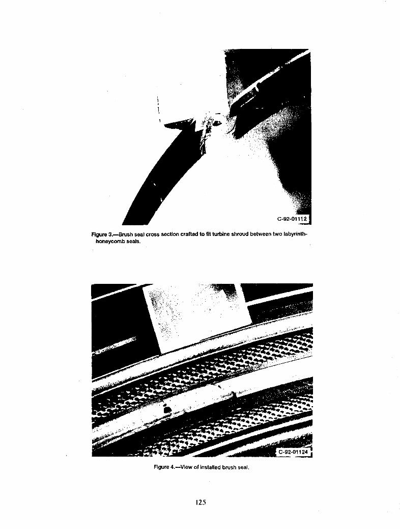
Figure3.mBrush seal crosssectioncrafted to fit turbine shroudbetween two labyrinth-honeycombseals.
C-92-01124j
Figure4.reView of installedbrushseal.
125

Figure5.--Overview of installedbrushseatand powerturbine housing.
126

C-g2,.00772
(a) Pressure tap hole.
(b) Thermocouple mount and pressure tap lines.
_i :_. C-92-00773
(c) Shroud ring with three seal segments and instru-mentation lines -- downstream view,
C-92-00774
(d) Shroud ring with three Seal segments and instru-mentation lines _ upstream view.
Figure 6.--Pressure tap and thermocouple locationson shroud seal.
127
Nozzle
stage48_ge3blade
Figure7._Schem=U¢ofpowerturbine.
Figure 8.--Fourth-stage turbine after testing, showing polishing of leading edges.
128

(a) Typical bdstle tips.
.j
N
o* . _,
(b) Surface features.
Figure 9.--Typical brush seal debris found in engine exhaust duct.
129

(b) Continued.
Figure g.---Continued.
130
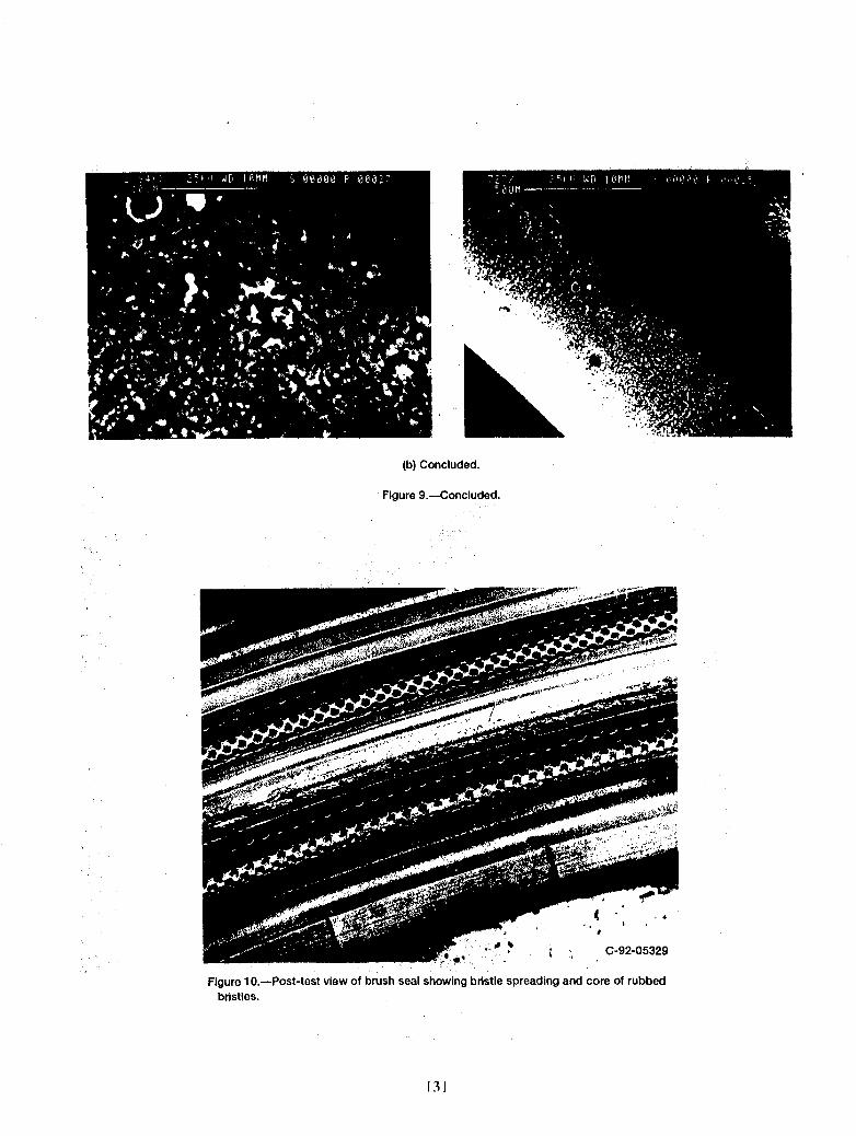
(b)Concluded.
Figure9.--.Concluded,
• !, . { , C-92-05329
Figure 10.--Post-test view of brushseal showingbdstle spreadingand core of rubbedbristles.
131

30x10_ 7- Photograph-r_ J+1.5 ,' number10 _ J+l,,-'( _ ,'
,20 n I• I
c I J+4.5
c 10 n I
0 -- ._ 0 ' I_o ,_ I Rotor
• _, II rub-10
m -5 __ _T_o IIo. I
-20 _ IJoint Joint
-10- -30 I I I I I I-100 0 100 200 300 400 500
Circumferentialposition, d_
(a) Bdstleheightversuscircumferentialposition.
/;
JoinL J + 1. J + 1.5.
J+2. J + 2.5. J+3.
(b)Bdstlesat backingwasher.
Figure11.--Post-test bristlestub heightand backingwasher rub. Bdstlediameter, 0.0028 in.
132

J + 3 (rotated view)40x. J + 3 (rotated view) 23x.
(b) Concluded.
Figure 11 .--Continued.
133

Flow
(c) Wear track and fence rub.
(d)Joint wear track.
Figure11 .--Concluded.
134

Figure12.--Details of brushseal wear pattem.
135

(a) BrisUeI spread away from wear track.
(b) Analysisof bristle1.
Figure13.mPost-test metallographlcresultsfor singlebristle.
136

[]
(c) Bristle1 at increasedresolution,
Figure13.--Concluded.
137
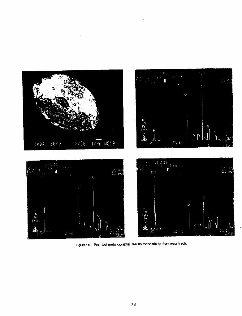
Figure14.--Post-test metallographlcresultsfor bristle tip from wear track.
138