Embed Size (px)
Citation preview
Smartcards and contactless smartcards
Integrators's and Implementer's Guide
www.springcard.com
Ref. PMD17041-AA
Smartcards and contactless smartcardsIntegrators's and Implementer's Guide
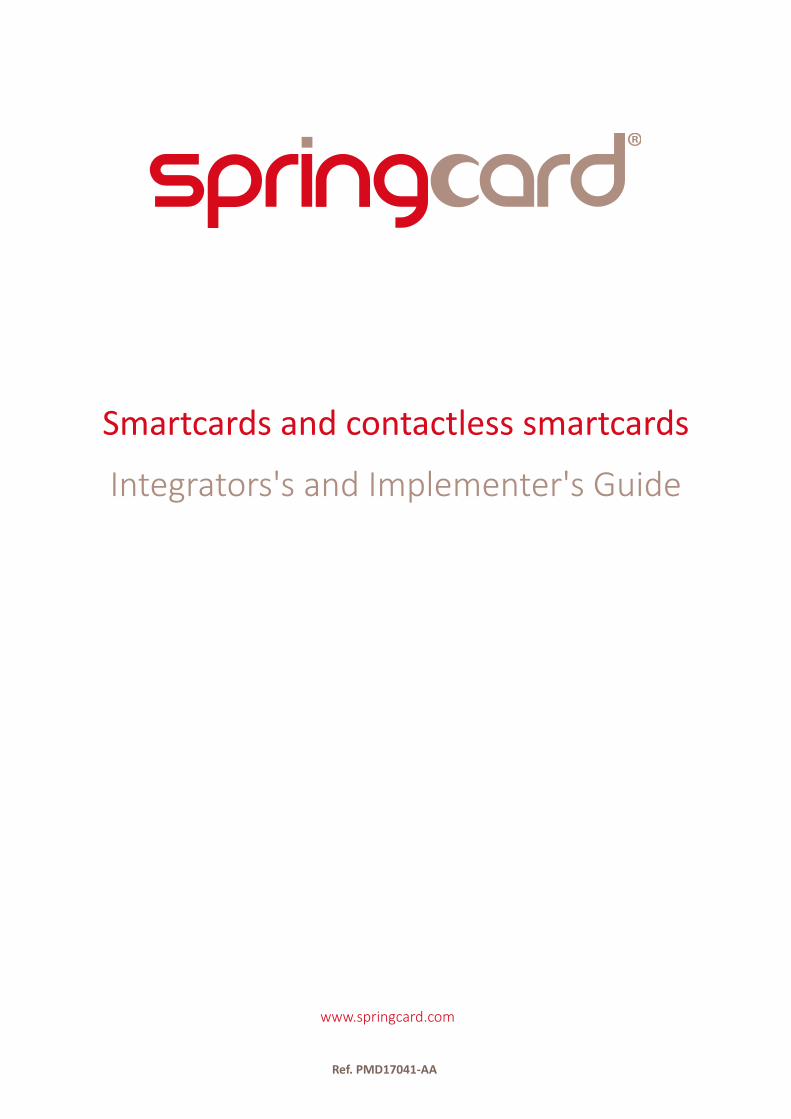
Document identificationCategory Developer's Manual
Classification Public
Reference PMD17041
Version AA
Status Approved
Keywords
Abstract
File name [PMD17041-AA] Smartcards and contactless smartcards - Integrator's and Implementers's Guide.odt
Print date 19/01/18
Revision history
Ver. Date AuthorValid. by Approv.
by DetailsTech. Qual.
AA 08/01/18 JDA CMA JDA Creation
All information in this document is subject to the disclaimers stated on last page.
PMD17041 - AA Page 2 / 128
Smartcards and contactless smartcardsIntegrators's and Implementer's Guide
Contents1. Introduction...................................................................................................................................10
1.1. Overview...............................................................................................................................101.2. Audience................................................................................................................................101.3. Related documents...............................................................................................................111.4. Product listing........................................................................................................................111.5. Reference documents...........................................................................................................13
1.5.1. International standards.................................................................................................131.5.2. Public specifications......................................................................................................14
1.6. Support and updates............................................................................................................141.7. Conventions used in this document.....................................................................................15
1.7.1. Typographic conventions for numbers.........................................................................151.7.2. Object size.....................................................................................................................151.7.3. Iconography...................................................................................................................15
1.8. Glossary and acronyms.........................................................................................................162. Smartcards and couplers – Concepts and definitions.................................................................17
2.1. What is a smartcard?............................................................................................................172.2. What is a smartcard, according to ISO/IEC 7816.................................................................17
2.2.1. Form-factor and electrical interface.............................................................................172.2.2. Protocol.........................................................................................................................192.2.3. Software (application) interface...................................................................................212.2.4. The grammar.................................................................................................................222.2.5. The vocabulary..............................................................................................................23
2.3. Variations around ISO/IEC 7816...........................................................................................302.3.1. SAM and HSM...............................................................................................................302.3.2. Secure elements and other “smartcard chips without card”......................................302.3.3. Wired-logic, storage only card......................................................................................322.3.4. Contactless cards..........................................................................................................332.3.5. Wired-logic, storage only contactless cards.................................................................34
2.4. The coupling device or coupler............................................................................................343. Contactless cards, RFID, NFC – concepts and standards.............................................................35
3.1. ‘Proximity’ contactless smartcards.......................................................................................353.1.1. Basics.............................................................................................................................353.1.2. The standards for proximity cards................................................................................373.1.3. Polling............................................................................................................................383.1.4. Anticollision...................................................................................................................393.1.5. Single card approach.....................................................................................................393.1.6. Transport and application protocols............................................................................403.1.7. Contactless smartcards and PC/SC...............................................................................413.1.8. Contactless only, dual, two-chip cards.........................................................................41
3.2. Wired-logic proximity contactless cards..............................................................................42
All information in this document is subject to the disclaimers stated on last page.
PMD17041 - AA Page 3 / 128
Smartcards and contactless smartcardsIntegrators's and Implementer's Guide
3.2.1. Support of wired-logic cards by standard PCDs...........................................................423.2.2. Support of wired-logic contactless cards under PC/SC...............................................43
3.3. Operating distance: size matters..........................................................................................443.3.1. Decrease of the RF field with the distance to the PCD................................................443.3.2. Field level required by the PICC....................................................................................453.3.3. Size of the PICC.............................................................................................................463.3.4. Which classes a coupler has to support?.....................................................................493.3.5. Actual operating distance.............................................................................................49
3.4. ‘Vicinity’ contactless cards....................................................................................................513.4.1. The need for hand free systems...................................................................................513.4.2. The standards................................................................................................................523.4.3. Vicinity contactless cards vs RFID HF tags or labels.....................................................54
3.5. NFC Tags................................................................................................................................563.5.1. NFC and the NFC Forum...............................................................................................563.5.2. The concept behind NFC Tags......................................................................................573.5.3. NFC Forum Data Exchange Format and Record Types.................................................573.5.4. List of compliant PICCs / VICCs.....................................................................................58
3.6. Key actors and brands...........................................................................................................613.6.1. NXP, ex Philips Semiconductors....................................................................................613.6.2. STMicroElectronics........................................................................................................653.6.3. Infineon.........................................................................................................................663.6.4. Texas Instrument...........................................................................................................663.6.5. Atmel (now Microchip).................................................................................................67
4. PC/SC Stack – role, specificities, alternatives...............................................................................684.1. Introduction...........................................................................................................................684.2. The PC/SC architecture (and vocabulary)............................................................................68
4.2.1. Smartcards, readers and drivers...................................................................................684.2.2. The middleware............................................................................................................694.2.3. The API...........................................................................................................................694.2.4. Helpers..........................................................................................................................69
4.3. PC/SC on Microsoft Windows...............................................................................................714.3.1. Official documentation.................................................................................................714.3.2. Technical implementation.............................................................................................724.3.3. Writing and using card helpers.....................................................................................724.3.4. Limitations.....................................................................................................................73
4.4. Linux and other UNIX-like systems.......................................................................................734.5. macOS X.................................................................................................................................744.6. Android..................................................................................................................................75
5. An application that uses PC/SC – Introduction to the API and typical workflow.......................765.1. Introduction...........................................................................................................................765.2. Establish a PC/SC context......................................................................................................775.3. List the PC/SC couplers.........................................................................................................785.4. Is there a card in the coupler?..............................................................................................805.5. Connect to the card..............................................................................................................82
All information in this document is subject to the disclaimers stated on last page.
PMD17041 - AA Page 4 / 128
Smartcards and contactless smartcardsIntegrators's and Implementer's Guide
5.6. Send commands to the card – and receive its responses...................................................845.7. Retrieve a coupler’s (or driver’s) meta-data........................................................................865.8. How to retrieve the card’s ATR?...........................................................................................87
5.8.1. SCardGetAttrib method................................................................................................875.8.2. SCardGetStatusChange method...................................................................................885.8.3. SCardStatus method.....................................................................................................89
5.9. Disconnect from the card.....................................................................................................905.10. Release the PC/SC context..................................................................................................91
6. Using contactless cards with PC/SC..............................................................................................926.1. Introduction...........................................................................................................................926.2. Connecting to a contactless card.........................................................................................92
6.2.1. Protocol.........................................................................................................................926.2.2. Share mode...................................................................................................................936.2.3. Sample code..................................................................................................................94
6.3. Retrieving the card’s protocol level ID..................................................................................966.3.1. Motivation.....................................................................................................................966.3.2. ID name, length and construction among the standards............................................976.3.3. Are ISO/IEC 14443 A 4-byte UIDs really unique?.........................................................986.3.4. Random IDs...................................................................................................................986.3.5. The GET DATA (ID) instruction......................................................................................99
6.4. Recognizing the contactless card type...............................................................................1016.4.1. The ATR of a wired-logic contactless card..................................................................1026.4.2. The ATR of a contactless smartcard...........................................................................1066.4.3. Obtaining technical data through the GET DATA instruction....................................107
6.5. Exchanging APDUs with a contactless smartcard..............................................................1076.5.1. Case of a smartcard fully compliant with ISO/IEC 7816-4.........................................1086.5.2. Case of a smartcard having a custom APDU format..................................................109
6.6. The embedded APDU Processor for wired-logic cards......................................................1136.6.1. Generic wired-logic card read/write instructions......................................................1136.6.2. MIFARE Classic authentication and keys....................................................................1136.6.3. ISO/IEC 15693-3 instructions......................................................................................114
7. Creating efficient and robust PC/SC applications......................................................................1157.1. Connecting to the right coupler.........................................................................................115
7.1.1. Coupler names (and the issues behind that).............................................................1157.1.2. Identifying a SpringCard PC/SC contactless coupler..................................................116
7.2. Using background threads..................................................................................................1177.2.1. Monitoring the coupler(s) and card(s) in background..............................................1177.2.2. SCardConnect “loop” in the background...................................................................1187.2.3. SCardTransmit in the background..............................................................................118
7.3. Recommended flowchart with 1+2 threads......................................................................1197.4. Understanding the errors (and implementing a smart recovery).....................................120
7.4.1. Errors that should be recovered nicely by the application........................................1217.4.2. “User related” errors..................................................................................................1217.4.3. Errors that shall never occur after the application has been debugged..................122
All information in this document is subject to the disclaimers stated on last page.
PMD17041 - AA Page 5 / 128
Smartcards and contactless smartcardsIntegrators's and Implementer's Guide
7.4.4. System errors..............................................................................................................1228. Smartcard applications without PC/SC......................................................................................123
8.1. SpringCard zero-driver CCID implementation....................................................................1238.2. Android lightweight CCID implementation........................................................................124
8.2.1. Motivation...................................................................................................................1248.2.2. Technical architecture.................................................................................................1248.2.3. Frequent issues with mainstream Android tablets....................................................126
All information in this document is subject to the disclaimers stated on last page.
PMD17041 - AA Page 6 / 128
Smartcards and contactless smartcardsIntegrators's and Implementer's Guide
Illustration indexIllustration 1: Smartcard formats.......................................................................................................18Illustration 2: Smartcard contacts.....................................................................................................18Illustration 3: Principles of card operation: power-up, ATR, and command/response sequences.20Illustration 4: Format of C-APDUs.....................................................................................................22Illustration 5: Format of R-APDUs.....................................................................................................23Illustration 6: The contact and contactless protocol stacks..............................................................33Illustration 7: PCD → PICC remote power principle.........................................................................36Illustration 8: How the card and the coupler communicates...........................................................36Illustration 9: A first-generation's dual-access card, featuring a copper coil welded behind theISO/IEC 7816 module.........................................................................................................................42Illustration 10: RF field level against distance to the antenna, with the same H0, for differentdiameters...........................................................................................................................................44Illustration 11: RF field level against distance to the antenna, for different actual readers...........45Illustration 12: The SpringField Florida is a small testing tool, based on a NXP NTAG chip, thatshows how far the RF field is strong enough to power a contactless card......................................46Illustration 13: Definition of PICC classes 1, 2 and 3........................................................................47Illustration 14: Definition of PICC classes 4, 5 and 6........................................................................48Illustration 15: RF field level against distance to the antenna, for different readers, up to 25 cm 53Illustration 16: Outprint of a MIFARE Classic promotional card.......................................................61Illustration 17: The PC/SC stack.........................................................................................................70Illustration 18: A minimal C function to list the PC/SC couplers......................................................79Illustration 19: Basic implementation of SCardGetStatusChange....................................................81Illustration 20: Flowchart of a PC/SC application with 3 threads...................................................119Illustration 21: The lighweight "PS/SC Like" architecture proposed by SpringCard for Android. .125Illustration 22: A Nexus 9 Android Tablet with a Prox'N'Roll PC/SC HSP........................................126
All information in this document is subject to the disclaimers stated on last page.
PMD17041 - AA Page 7 / 128
Smartcards and contactless smartcardsIntegrators's and Implementer's Guide
Table indexTable 1: Excerpt of the ISO/IEC 7816-4 of INS values.......................................................................27Table 2: Excerpt of the ISO/IEC 7816-4 listing of status words........................................................29Table 3: Understanding of the protocol level ID for the different standards...................................97Table 4: List of manufacturer codes (partial)....................................................................................98Table 5: ATR of a wired-logic contactless card................................................................................102Table 6: Values for the ATR's PIX.SS byte.........................................................................................103Table 7: Values for the ATR's PIX.NN word......................................................................................105Table 8: ATR of a contactless smartcard..........................................................................................106Table 9: GET DATA: P1,P2 specific values........................................................................................107Table 10: The DESFire GET VERSION command..............................................................................109Table 11: PC/SC READ/WRITE instructions for wired-logic cards...................................................113Table 12: PC/SC implementation of MIFARE Classic security.........................................................113Table 13: Embedded APDU Processor: mapping of ISO/IEC 15693-3 instructions.......................114Table 14: CCID commands/responses.............................................................................................124
All information in this document is subject to the disclaimers stated on last page.
PMD17041 - AA Page 8 / 128

Smartcards and contactless smartcardsIntegrators's and Implementer's Guide
This guide book has been written for SpringCard by Johann Dantant.Thanks to Laetitia Cochet for her contributions, Claire Maillet for her careful re-reading, and all
the SpringCard R&D team for the technical inputs.
Warning
A few parts of this guide make reference to future documents, features or products, that are not yet available at the date of writing.
Such items are written in blue and associated to the “coming soon” or “TBD” (to be done) words.
All information in this document is subject to the disclaimers stated on last page.
PMD17041 - AA Page 9 / 128
Smartcards and contactless smartcardsIntegrators's and Implementer's Guide
1. Introduction
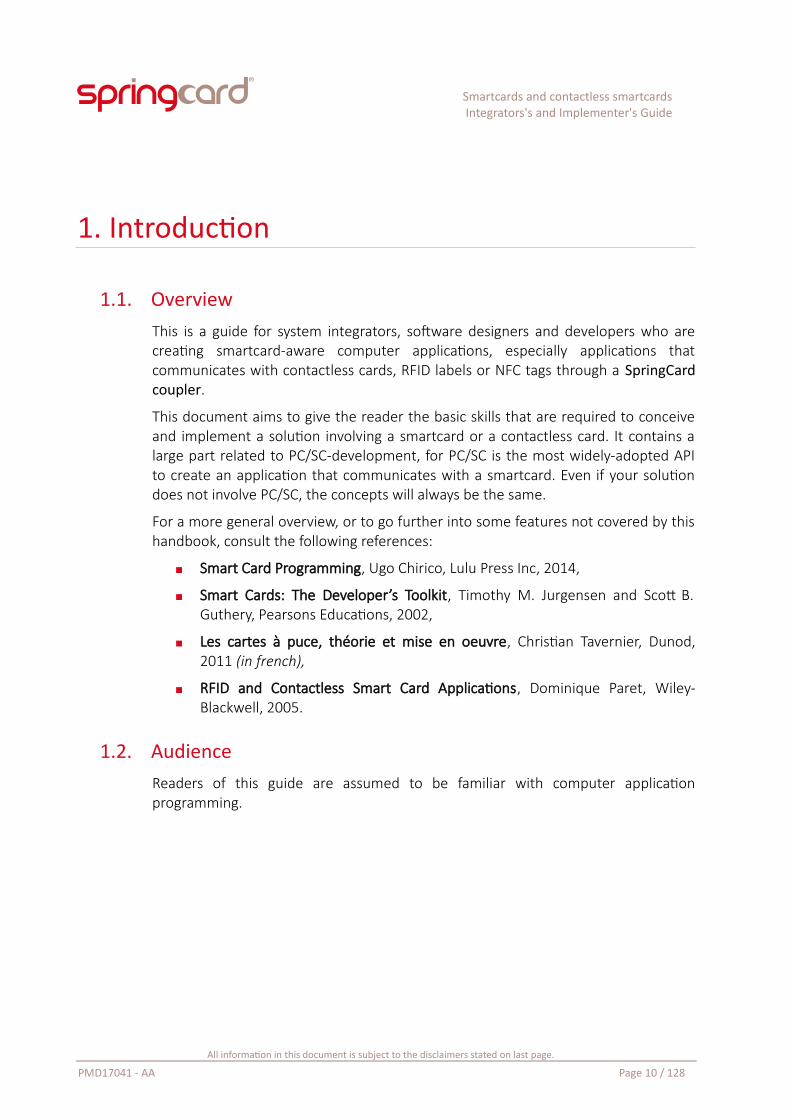
1.1. OverviewThis is a guide for system integrators, software designers and developers who arecreating smartcard-aware computer applications, especially applications thatcommunicates with contactless cards, RFID labels or NFC tags through a SpringCardcoupler.
This document aims to give the reader the basic skills that are required to conceiveand implement a solution involving a smartcard or a contactless card. It contains alarge part related to PC/SC-development, for PC/SC is the most widely-adopted APIto create an application that communicates with a smartcard. Even if your solutiondoes not involve PC/SC, the concepts will always be the same.
For a more general overview, or to go further into some features not covered by thishandbook, consult the following references:
Smart Card Programming, Ugo Chirico, Lulu Press Inc, 2014,
Smart Cards: The Developer’s Toolkit, Timothy M. Jurgensen and Scott B.Guthery, Pearsons Educations, 2002,
Les cartes à puce, théorie et mise en oeuvre, Christian Tavernier, Dunod,2011 (in french),
RFID and Contactless Smart Card Applications, Dominique Paret, Wiley-Blackwell, 2005.
1.2. AudienceReaders of this guide are assumed to be familiar with computer applicationprogramming.
All information in this document is subject to the disclaimers stated on last page.
PMD17041 - AA Page 10 / 128
Smartcards and contactless smartcardsIntegrators's and Implementer's Guide
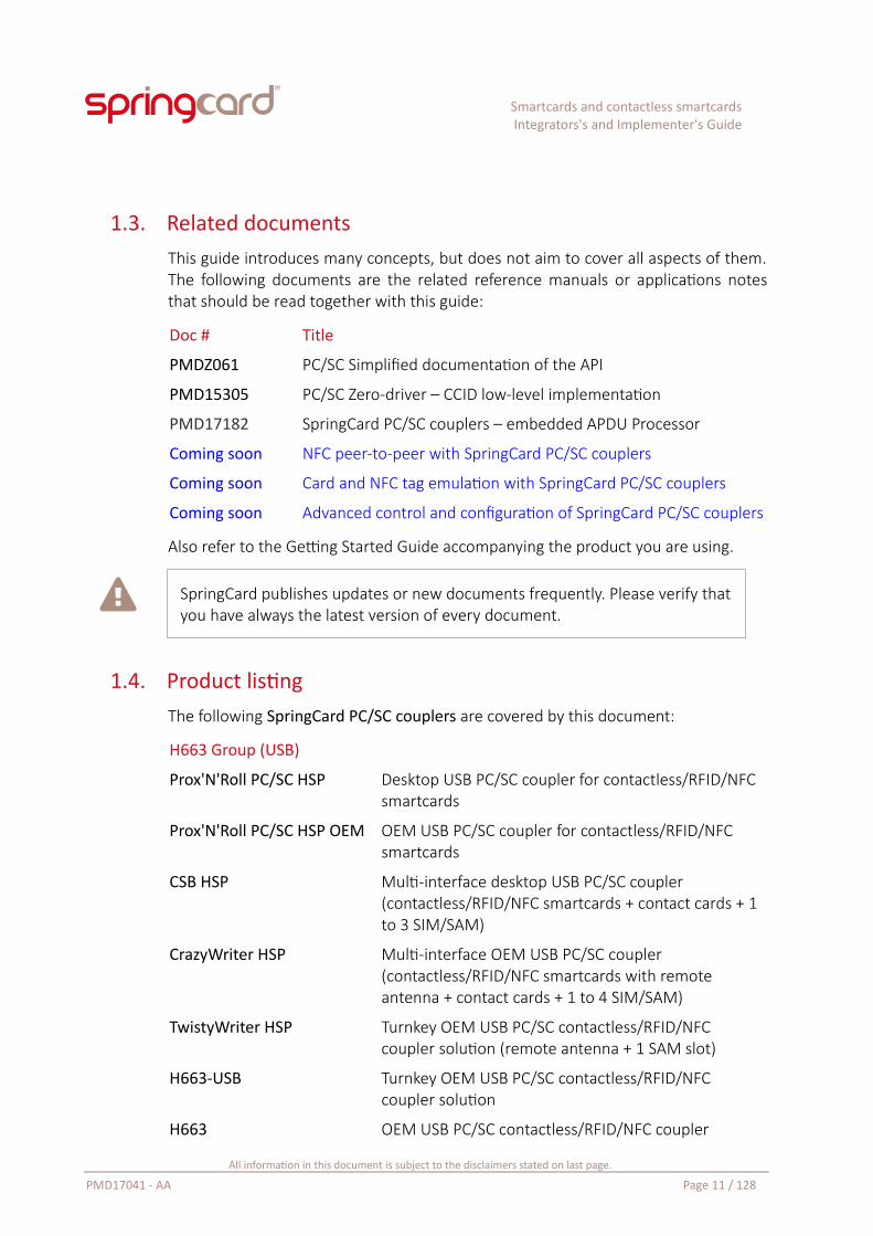
1.3. Related documentsThis guide introduces many concepts, but does not aim to cover all aspects of them.The following documents are the related reference manuals or applications notesthat should be read together with this guide:
Doc # Title
PMDZ061 PC/SC Simplified documentation of the API
PMD15305 PC/SC Zero-driver – CCID low-level implementation
PMD17182 SpringCard PC/SC couplers – embedded APDU Processor
Coming soon NFC peer-to-peer with SpringCard PC/SC couplers
Coming soon Card and NFC tag emulation with SpringCard PC/SC couplers
Coming soon Advanced control and configuration of SpringCard PC/SC couplers
Also refer to the Getting Started Guide accompanying the product you are using.
SpringCard publishes updates or new documents frequently. Please verify thatyou have always the latest version of every document.
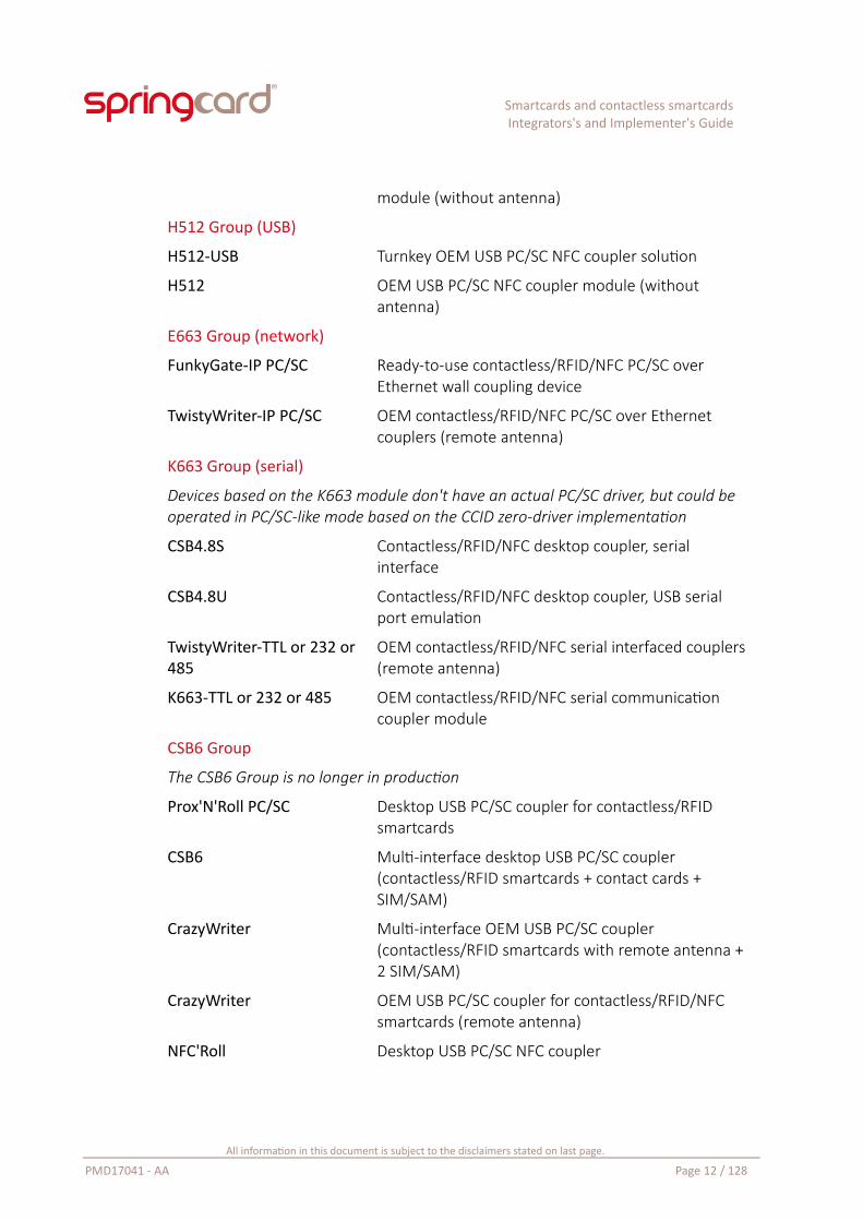
1.4. Product listingThe following SpringCard PC/SC couplers are covered by this document:
H663 Group (USB)
Prox'N'Roll PC/SC HSP Desktop USB PC/SC coupler for contactless/RFID/NFC smartcards
Prox'N'Roll PC/SC HSP OEM OEM USB PC/SC coupler for contactless/RFID/NFC smartcards
CSB HSP Multi-interface desktop USB PC/SC coupler (contactless/RFID/NFC smartcards + contact cards + 1 to 3 SIM/SAM)
CrazyWriter HSP Multi-interface OEM USB PC/SC coupler (contactless/RFID/NFC smartcards with remote antenna + contact cards + 1 to 4 SIM/SAM)
TwistyWriter HSP Turnkey OEM USB PC/SC contactless/RFID/NFC coupler solution (remote antenna + 1 SAM slot)
H663-USB Turnkey OEM USB PC/SC contactless/RFID/NFC coupler solution
H663 OEM USB PC/SC contactless/RFID/NFC coupler
All information in this document is subject to the disclaimers stated on last page.
PMD17041 - AA Page 11 / 128
Smartcards and contactless smartcardsIntegrators's and Implementer's Guide
module (without antenna)
H512 Group (USB)
H512-USB Turnkey OEM USB PC/SC NFC coupler solution
H512 OEM USB PC/SC NFC coupler module (without antenna)
E663 Group (network)
FunkyGate-IP PC/SC Ready-to-use contactless/RFID/NFC PC/SC over Ethernet wall coupling device
TwistyWriter-IP PC/SC OEM contactless/RFID/NFC PC/SC over Ethernet couplers (remote antenna)
K663 Group (serial)
Devices based on the K663 module don't have an actual PC/SC driver, but could be operated in PC/SC-like mode based on the CCID zero-driver implementation
CSB4.8S Contactless/RFID/NFC desktop coupler, serial interface
CSB4.8U Contactless/RFID/NFC desktop coupler, USB serial port emulation
TwistyWriter-TTL or 232 or 485
OEM contactless/RFID/NFC serial interfaced couplers (remote antenna)
K663-TTL or 232 or 485 OEM contactless/RFID/NFC serial communication coupler module
CSB6 Group
The CSB6 Group is no longer in production
Prox'N'Roll PC/SC Desktop USB PC/SC coupler for contactless/RFID smartcards
CSB6 Multi-interface desktop USB PC/SC coupler (contactless/RFID smartcards + contact cards + SIM/SAM)
CrazyWriter Multi-interface OEM USB PC/SC coupler (contactless/RFID smartcards with remote antenna + 2 SIM/SAM)
CrazyWriter OEM USB PC/SC coupler for contactless/RFID/NFC smartcards (remote antenna)
NFC'Roll Desktop USB PC/SC NFC coupler
All information in this document is subject to the disclaimers stated on last page.
PMD17041 - AA Page 12 / 128
Smartcards and contactless smartcardsIntegrators's and Implementer's Guide
Please refer to each product’s page on www.springcard.com to download therelevant datasheet, getting started guide, and associated documents.
SpringCard introduces new products frequently. Latests products may not appear on the list, while being also covered by this document.
1.5. Reference documents
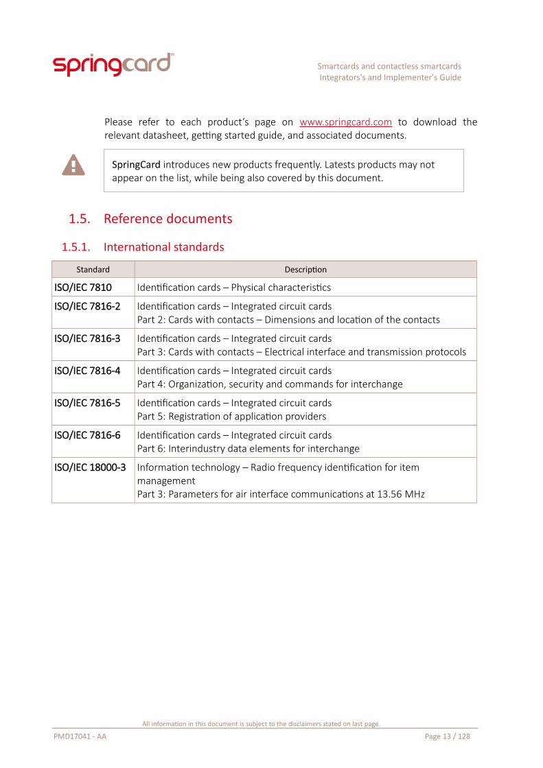
1.5.1. International standards
Standard Description
ISO/IEC 7810 Identification cards – Physical characteristics
ISO/IEC 7816-2 Identification cards – Integrated circuit cardsPart 2: Cards with contacts – Dimensions and location of the contacts
ISO/IEC 7816-3 Identification cards – Integrated circuit cardsPart 3: Cards with contacts – Electrical interface and transmission protocols
ISO/IEC 7816-4 Identification cards – Integrated circuit cardsPart 4: Organization, security and commands for interchange
ISO/IEC 7816-5 Identification cards – Integrated circuit cardsPart 5: Registration of application providers
ISO/IEC 7816-6 Identification cards – Integrated circuit cardsPart 6: Interindustry data elements for interchange
ISO/IEC 18000-3 Information technology – Radio frequency identification for item managementPart 3: Parameters for air interface communications at 13.56 MHz
All information in this document is subject to the disclaimers stated on last page.
PMD17041 - AA Page 13 / 128
Smartcards and contactless smartcardsIntegrators's and Implementer's Guide
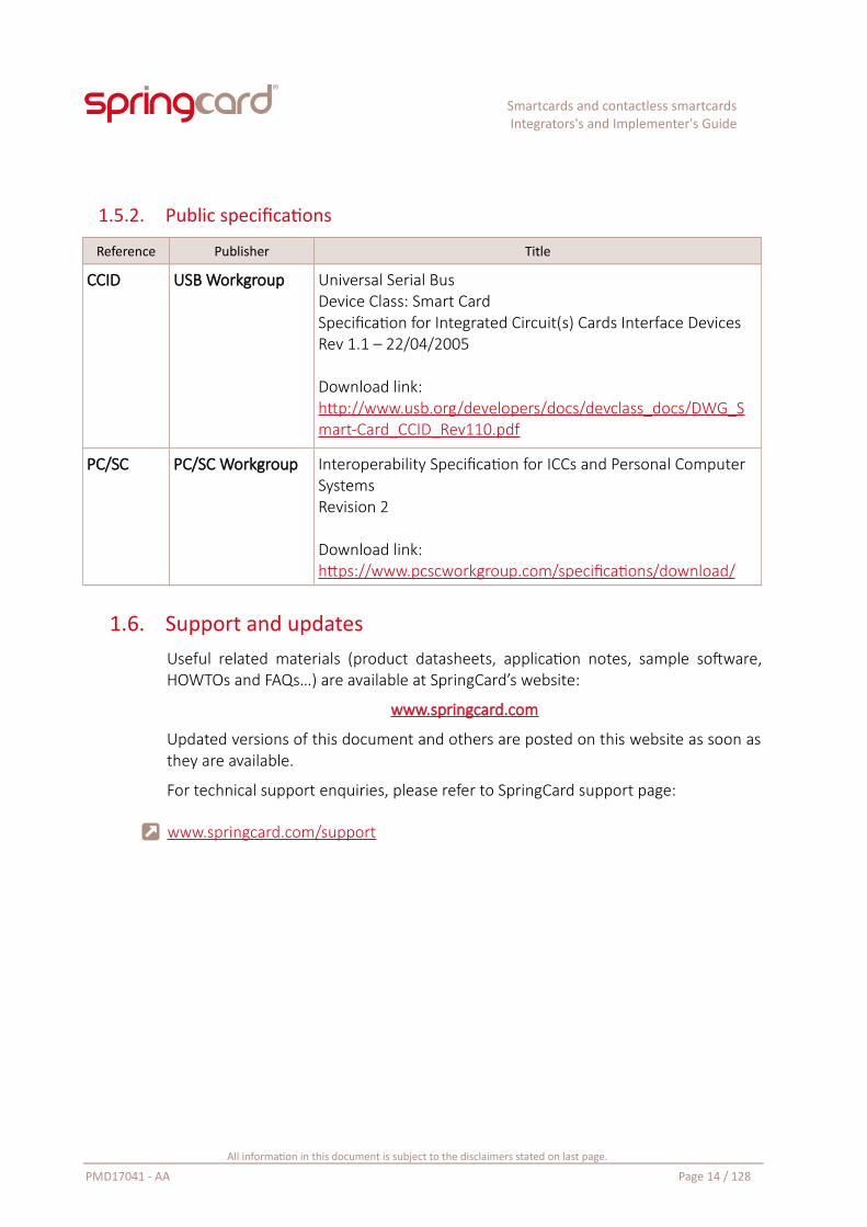
1.5.2. Public specifications
Reference Publisher Title
CCID USB Workgroup Universal Serial BusDevice Class: Smart CardSpecification for Integrated Circuit(s) Cards Interface DevicesRev 1.1 – 22/04/2005
Download link:http://www.usb.org/developers/docs/devclass_docs/DWG_Smart-Card_CCID_Rev110.pdf
PC/SC PC/SC Workgroup Interoperability Specification for ICCs and Personal Computer SystemsRevision 2
Download link:https://www.pcscworkgroup.com/specifications/download/
1.6. Support and updatesUseful related materials (product datasheets, application notes, sample software,HOWTOs and FAQs…) are available at SpringCard’s website:
www.springcard.com
Updated versions of this document and others are posted on this website as soon asthey are available.
For technical support enquiries, please refer to SpringCard support page:
www.springcard.com/support
All information in this document is subject to the disclaimers stated on last page.
PMD17041 - AA Page 14 / 128
Smartcards and contactless smartcardsIntegrators's and Implementer's Guide
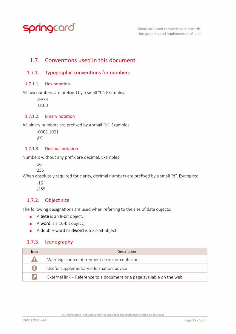
1.7. Conventions used in this document
1.7.1. Typographic conventions for numbers
1.7.1.1. Hex notation
All hex numbers are prefixed by a small “h”. Examples:
h9AE4h0100
1.7.1.2. Binary notation
All binary numbers are prefixed by a small “b”. Examples:
b0001 1001b01
1.7.1.3. Decimal notation
Numbers without any prefix are decimal. Examples:16255
When absolutely required for clarity, decimal numbers are prefixed by a small “d”. Examples:
d16d255
1.7.2. Object size
The following designations are used when referring to the size of data objects: A byte is an 8-bit object, A word is a 16-bit object, A double-word or dword is a 32-bit object.
1.7.3. Iconography
Icon Description
Warning: source of frequent errors or confusions
Useful supplementary information, advice
External link – Reference to a document or a page available on the web
All information in this document is subject to the disclaimers stated on last page.
PMD17041 - AA Page 15 / 128
Smartcards and contactless smartcardsIntegrators's and Implementer's Guide
1.8. Glossary and acronymsThe terms used in this document as generally defined on the first time they are used.The most common terms are listed below:
APDU Application Protocol Datagram UnitRefer to a ISO/IEC 7816-4 command (C-APDU) or response (R-APDU)
ATR Answer To Reset
CLA ClassThe 1st byte of a ISO/IEC 7816-4 command (C-APDU)
CSN Card Serial Number(see also UID, RID, PUPI)
INS InstructionThe 2nd byte of a ISO/IEC 7816-4 command (C-APDU)
NFC Near Field Communication
PCD Proximity Coupling Device
PICC Proximity Integrated Circuit Card
PPS Parameter & Protocol Selection
RFID Radio Frequency IDentification
SW Status WordThe 2 status bytes at the end of a ISO/IEC 7816-4 response (R-APDU)
TPDU Transport Protocol Datagram UnitRefer to a ISO/IEC 7816-3 or ISO/IEC 14443-4 block
VCD Vicinity Coupling Device
VICC Vicinity Integrated Circuit Card
A complete glossary is available on SpringCard’s Technical Blog:
http://tech.springcard.com/glossary/
All information in this document is subject to the disclaimers stated on last page.
PMD17041 - AA Page 16 / 128
Smartcards and contactless smartcardsIntegrators's and Implementer's Guide
2. Smartcards and couplers – Concepts and definitions
2.1. What is a smartcard?According to Wikipedia, “a smartcard, chip card or integrated circuit card (ICC) is anypocket-sized card that has embedded integrated circuits”.
https://en.wikipedia.org/wiki/Smart_card
This is a very open definition, which obviously would cover not only the objects youwould spontaneously name “smartcard”, but also the SD card of your digital cameraor mobile phone, the cartridges of the gaming console you used to play with as achild, and possibly a flat USB flash drive. Actually, all of these are “pocket-sized cardsthat has embedded integrated circuits” as well. But they are no smartcards.
At first, let’s circumscribe the subject to what the engineers and the industry havestandardised under the technical name ‘smartcard’: an IC card, having a standardisedsize, featuring a standardised electrical interface, implementing a standardisedprotocol, and finally exposing standardised software interfaces.
All these standards are grouped in the ISO/IEC 7816 cluster, entitled “identificationcards – integrated circuit cards”.
From now on, we are leaving Wikipedia’s open definition behind us, and will considerthat a smartcard is an electronic device that obeys to (at least some of) the ISO/IEC7816 standards.
2.2. What is a smartcard, according to ISO/IEC 7816
2.2.1. Form-factor and electrical interface
ISO/IEC 7816-1 says the form-factor of a smartcard must be ID-1, as defined in ISO7810, i.e. the “credit card” size we all know (85.60×63.98 mm, 3.37×2.13 in).
A few smaller form-factors have been introduced year after year by mobile phonesmanufacturer, and are now widely adopted:
2FF “mini SIM” for the mobile phone manufacturers (25×15 mm,0.98×0.59 in) has also been adopted by the smartcard industry for securitycoprocessors (SAM) under the name ID-000,
All information in this document is subject to the disclaimers stated on last page.
PMD17041 - AA Page 17 / 128
Smartcards and contactless smartcardsIntegrators's and Implementer's Guide
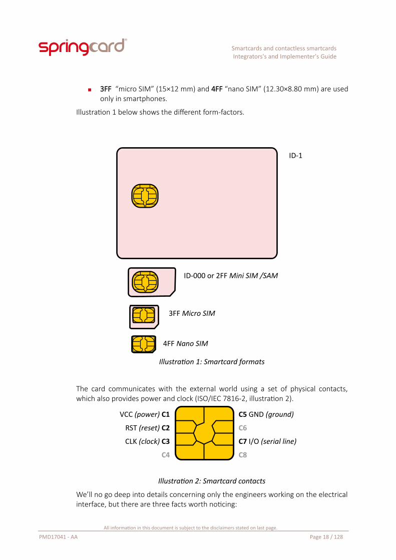
3FF “micro SIM” (15×12 mm) and 4FF “nano SIM” (12.30×8.80 mm) are usedonly in smartphones.
Illustration 1 below shows the different form-factors.
Illustration 1: Smartcard formats
The card communicates with the external world using a set of physical contacts,which also provides power and clock (ISO/IEC 7816-2, illustration 2).
Illustration 2: Smartcard contacts
We’ll no go deep into details concerning only the engineers working on the electricalinterface, but there are three facts worth noticing:
All information in this document is subject to the disclaimers stated on last page.
PMD17041 - AA Page 18 / 128
C5 GND (ground)
C6
C7 I/O (serial line)
C8
VCC (power) C1
RST (reset) C2
CLK (clock) C3
C4
ID-1
ID-000 or 2FF Mini SIM /SAM
3FF Micro SIM
4FF Nano SIM
Smartcards and contactless smartcardsIntegrators's and Implementer's Guide
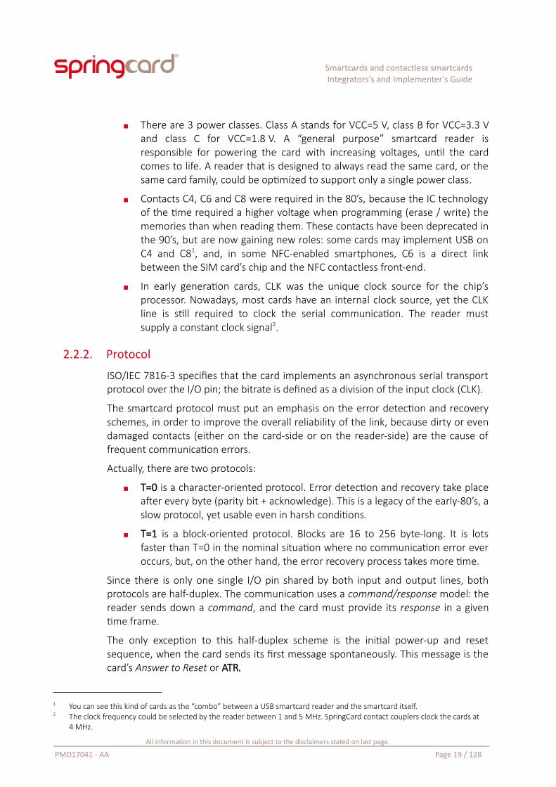
There are 3 power classes. Class A stands for VCC=5 V, class B for VCC=3.3 Vand class C for VCC=1.8 V. A “general purpose” smartcard reader isresponsible for powering the card with increasing voltages, until the cardcomes to life. A reader that is designed to always read the same card, or thesame card family, could be optimized to support only a single power class.
Contacts C4, C6 and C8 were required in the 80’s, because the IC technologyof the time required a higher voltage when programming (erase / write) thememories than when reading them. These contacts have been deprecated inthe 90’s, but are now gaining new roles: some cards may implement USB onC4 and C81, and, in some NFC-enabled smartphones, C6 is a direct linkbetween the SIM card’s chip and the NFC contactless front-end.
In early generation cards, CLK was the unique clock source for the chip’sprocessor. Nowadays, most cards have an internal clock source, yet the CLKline is still required to clock the serial communication. The reader mustsupply a constant clock signal2.
2.2.2. Protocol
ISO/IEC 7816-3 specifies that the card implements an asynchronous serial transportprotocol over the I/O pin; the bitrate is defined as a division of the input clock (CLK).
The smartcard protocol must put an emphasis on the error detection and recoveryschemes, in order to improve the overall reliability of the link, because dirty or evendamaged contacts (either on the card-side or on the reader-side) are the cause offrequent communication errors.
Actually, there are two protocols:
T=0 is a character-oriented protocol. Error detection and recovery take placeafter every byte (parity bit + acknowledge). This is a legacy of the early-80’s, aslow protocol, yet usable even in harsh conditions.
T=1 is a block-oriented protocol. Blocks are 16 to 256 byte-long. It is lotsfaster than T=0 in the nominal situation where no communication error everoccurs, but, on the other hand, the error recovery process takes more time.
Since there is only one single I/O pin shared by both input and output lines, bothprotocols are half-duplex. The communication uses a command/response model: thereader sends down a command, and the card must provide its response in a giventime frame.
The only exception to this half-duplex scheme is the initial power-up and resetsequence, when the card sends its first message spontaneously. This message is thecard’s Answer to Reset or ATR.
1 You can see this kind of cards as the “combo” between a USB smartcard reader and the smartcard itself.2 The clock frequency could be selected by the reader between 1 and 5 MHz. SpringCard contact couplers clock the cards at
4 MHz.
All information in this document is subject to the disclaimers stated on last page.
PMD17041 - AA Page 19 / 128
Smartcards and contactless smartcardsIntegrators's and Implementer's Guide
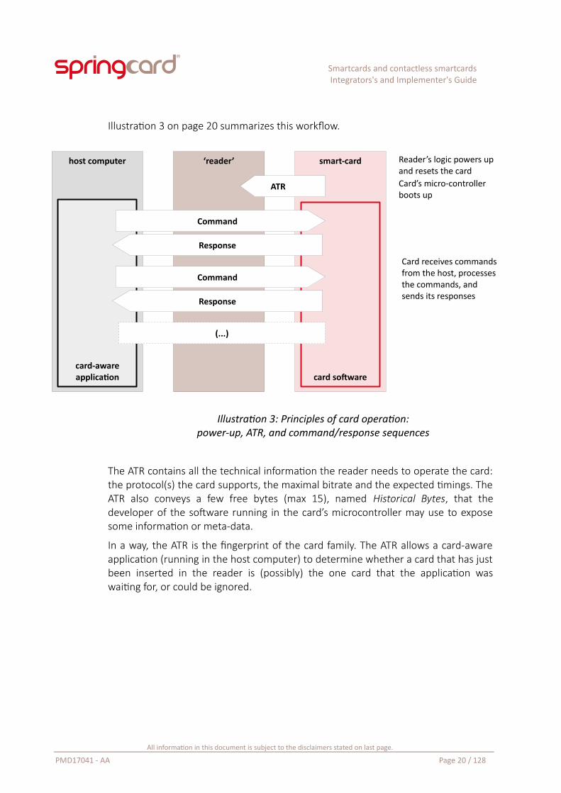
Illustration 3 on page 20 summarizes this workflow.
Illustration 3: Principles of card operation:power-up, ATR, and command/response sequences
The ATR contains all the technical information the reader needs to operate the card:the protocol(s) the card supports, the maximal bitrate and the expected timings. TheATR also conveys a few free bytes (max 15), named Historical Bytes, that thedeveloper of the software running in the card’s microcontroller may use to exposesome information or meta-data.
In a way, the ATR is the fingerprint of the card family. The ATR allows a card-awareapplication (running in the host computer) to determine whether a card that has justbeen inserted in the reader is (possibly) the one card that the application waswaiting for, or could be ignored.
All information in this document is subject to the disclaimers stated on last page.
PMD17041 - AA Page 20 / 128
Reader’s logic powers upand resets the cardCard’s micro-controllerboots up
host computer smart-card
card software
‘reader’
card-awareapplication
(...)
Card receives commandsfrom the host, processesthe commands, andsends its responses
Command
Response
Command
Response
ATR
Smartcards and contactless smartcardsIntegrators's and Implementer's Guide
Ludovic Rousseau, a smartcard professional and open-source enthusiast, has beenestablishing and maintaining for years a list of smartcard ATRs.
The complete list:
http://ludovic.rousseau.free.fr/softwares/pcsc-tools/smartcard_list.txt
He also provides an online tool to decode the ATR’s technical data and query his listof ATRs:
https://smartcard-atr.appspot.com/
SpringCard is not connected with and does not sponsor or endorse 3rd party open-source developers.
2.2.3. Software (application) interface
The T=0 and T=1 transport protocols as standardised in ISO/IEC 7816-3 convey (or“transport”) commands and responses between the card-aware software running inthe host and the software running in the smartcard.
ISO/IEC 7816-4 defines both the grammar and the vocabulary of the commands andresponses exchanged at application level, which are named application protocoldatagram units, or APDU3. The grammar is how the commands and responses areformatted. The vocabulary is the list of commands that shall/should be supported,and also the values of the success/error status in the responses.
To clarify the difference between the transport protocol and the application-levelgrammar/vocabulary, let’s have a look on HTTP, the application protocol behind theworld-wide web.
The web browser (HTTP client) expects that the HTTP server answers with anumerical status code, followed by some text data. This is the grammar. Status codeis defined to 200 for “OK, please display the following text nicely”, and 404 for “Notfound, the following text is an error message”. This is the vocabulary.
The command and the responses are conveyed by an underlying transport protocol,TCP, that is agnostic about the grammar/vocabulary used at application level.
3 The notion of APDU is not specific to the smartcard field. It has been introduced by network engineers in the early 70’s and standardised by ISO 7498 “Information Processing – Open Systems Interconnection – Basic Reference Model”, a standard that most network and system engineers know only as “the OSI model”. In the OSI model, T=0 and T=1 are transport protocols (4th layer); they convey TPDUs. The applications (7th layer) do exchange APDUs. But in most situations, the developer of the application would simply say “command / response” instead of “C-APDU / R-APDU”.
All information in this document is subject to the disclaimers stated on last page.
PMD17041 - AA Page 21 / 128
Smartcards and contactless smartcardsIntegrators's and Implementer's Guide
2.2.4. The grammar
2.2.4.1. Commands
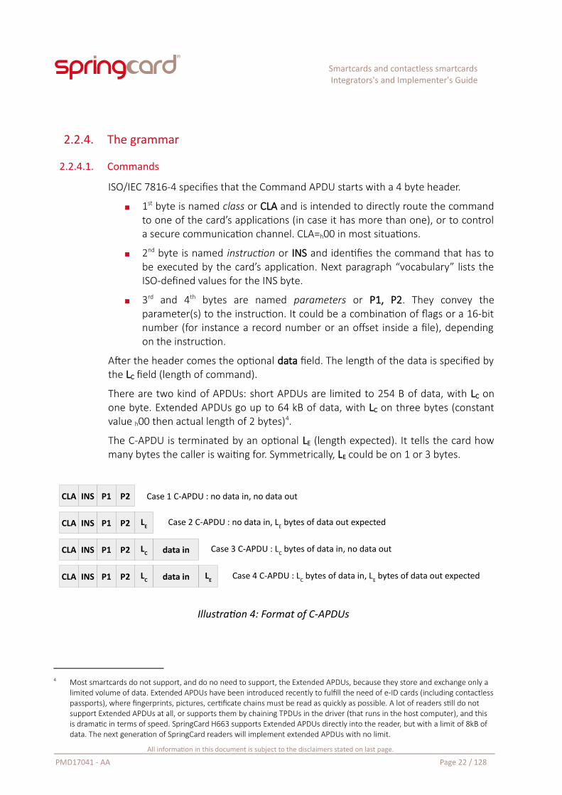
ISO/IEC 7816-4 specifies that the Command APDU starts with a 4 byte header.
1st byte is named class or CLA and is intended to directly route the commandto one of the card’s applications (in case it has more than one), or to controla secure communication channel. CLA=h00 in most situations.
2nd byte is named instruction or INS and identifies the command that has tobe executed by the card’s application. Next paragraph “vocabulary” lists theISO-defined values for the INS byte.
3rd and 4th bytes are named parameters or P1, P2. They convey theparameter(s) to the instruction. It could be a combination of flags or a 16-bitnumber (for instance a record number or an offset inside a file), dependingon the instruction.
After the header comes the optional data field. The length of the data is specified bythe LC field (length of command).
There are two kind of APDUs: short APDUs are limited to 254 B of data, with LC onone byte. Extended APDUs go up to 64 kB of data, with LC on three bytes (constantvalue h00 then actual length of 2 bytes)4.
The C-APDU is terminated by an optional LE (length expected). It tells the card howmany bytes the caller is waiting for. Symmetrically, LE could be on 1 or 3 bytes.
Illustration 4: Format of C-APDUs
4 Most smartcards do not support, and do no need to support, the Extended APDUs, because they store and exchange only a limited volume of data. Extended APDUs have been introduced recently to fulfill the need of e-ID cards (including contactlesspassports), where fingerprints, pictures, certificate chains must be read as quickly as possible. A lot of readers still do not support Extended APDUs at all, or supports them by chaining TPDUs in the driver (that runs in the host computer), and this is dramatic in terms of speed. SpringCard H663 supports Extended APDUs directly into the reader, but with a limit of 8kB of data. The next generation of SpringCard readers will implement extended APDUs with no limit.
All information in this document is subject to the disclaimers stated on last page.
PMD17041 - AA Page 22 / 128
CLA INS P1 P2 Case 1 C-APDU : no data in, no data out
CLA INS P1 P2 LC data in Case 3 C-APDU : LC bytes of data in, no data out
CLA INS P1 P2 LE Case 2 C-APDU : no data in, LE bytes of data out expected
CLA INS P1 P2 LC data in LE Case 4 C-APDU : LC bytes of data in, LE bytes of data out expected
Smartcards and contactless smartcardsIntegrators's and Implementer's Guide
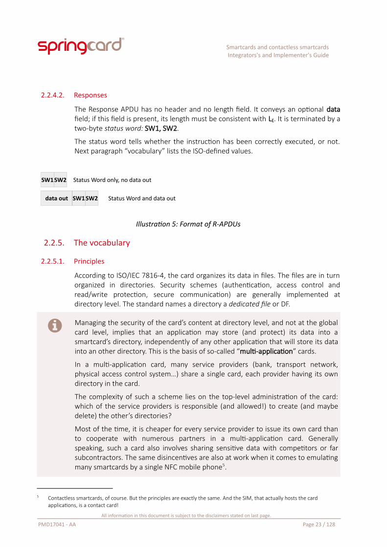
2.2.4.2. Responses
The Response APDU has no header and no length field. It conveys an optional datafield; if this field is present, its length must be consistent with LE. It is terminated by atwo-byte status word: SW1, SW2.
The status word tells whether the instruction has been correctly executed, or not.Next paragraph “vocabulary” lists the ISO-defined values.
Illustration 5: Format of R-APDUs
2.2.5. The vocabulary
2.2.5.1. Principles
According to ISO/IEC 7816-4, the card organizes its data in files. The files are in turnorganized in directories. Security schemes (authentication, access control andread/write protection, secure communication) are generally implemented atdirectory level. The standard names a directory a dedicated file or DF.
Managing the security of the card’s content at directory level, and not at the globalcard level, implies that an application may store (and protect) its data into asmartcard’s directory, independently of any other application that will store its datainto an other directory. This is the basis of so-called “multi-application” cards.
In a multi-application card, many service providers (bank, transport network,physical access control system…) share a single card, each provider having its owndirectory in the card.
The complexity of such a scheme lies on the top-level administration of the card:which of the service providers is responsible (and allowed!) to create (and maybedelete) the other’s directories?
Most of the time, it is cheaper for every service provider to issue its own card thanto cooperate with numerous partners in a multi-application card. Generallyspeaking, such a card also involves sharing sensitive data with competitors or farsubcontractors. The same disincentives are also at work when it comes to emulatingmany smartcards by a single NFC mobile phone5.
5 Contactless smartcards, of course. But the principles are exactly the same. And the SIM, that actually hosts the card applications, is a contact card!
All information in this document is subject to the disclaimers stated on last page.
PMD17041 - AA Page 23 / 128
SW1SW2 Status Word only, no data out
data out SW1 SW2 Status Word and data out
Smartcards and contactless smartcardsIntegrators's and Implementer's Guide
Under the directories or dedicated files (DF), there are elementary files (EF).Smartcard’s EFs are very different from regular computer files.
Firstly, they are not referred to by a file-name, but only by a short number (2 or even1 byte), because a smartcard is a small, resource constraint, chip.
Secondly, EFs are “smart” files: the instruction to read / write a file does not mapdirectly to “hey, please access this memory address and get / set this buffer there”,but is a (possibly complex) set of operations executed by the card’s software. Thisallows a few interesting features:
Record files could be seen as a kind of SQL table. The card’s softwaremanages the record structure and controls finely the access: depending onthe password or key that has been used for authentication, the grantedaccess could either be read only, or read + insert, or read + update, etc. Thecard’s software generally implements a transaction system with the recordfiles (more about that in paragraph 2.2.5.2).
Cyclic files are the same as record files, but when a new record is inserted,the oldest record is automatically overwritten. This is a must-have toimplement a transaction log efficiently in a size-constraint file-system!
Value or Counter files are single record-files that store a numeric value. Theyare associated to atomic, access-controlled operations (increase, decrease),all with boundary check.
Backup files are more like the standard files of your computer, but mirroredand associated to a powerful anti-tearing mechanism (more about that inparagraph 2.2.5.3).
Standard files do exists anyway; they are generally used to store largeamount of data that don’t change in the field.
Key files and a few other hidden files store the secret keys or passwords, andall the meta-data used by the card’s software to manage the access rights forthe other files. These files are never readable, and special managementinstructions must be used to change their content.
2.2.5.2. Transactions
Some card software feature a transaction system. It isn’t as complicated as atransactional SQL server, but implements the very same concept: maintaining thecoherence of the data stored in the card.
For example, if the card implements an electronic wallet; the merchant’s terminalmust take the money from the wallet (decrease a value file) and write an event inthe log (insert a record in a cyclic file). Without a transaction system, there’s a riskthat only one of the two operations is performed. But the transaction system
All information in this document is subject to the disclaimers stated on last page.
PMD17041 - AA Page 24 / 128
Smartcards and contactless smartcardsIntegrators's and Implementer's Guide
ensures that either both operations are performed at once (commit), or they areboth canceled (rollback).
A secure transaction system is at work in some cards and extends the principle onestep further. It uses cryptographic techniques, generally a CMAC (cryptographic-message authentication code) computed other all the commands and data involvedin the transaction. The CMAC is computed symmetrically in the smartcard and by thehost’s card-aware application6. The host application sends its commit instructiontogether with the CMAC, and the card compares this input with its own; the wholetransaction is canceled if the authentication cryptograms don’t match.
Doing so, even a defrauding software, running in the same host computer as thegenuine card-aware application, will not be able to change the card’s content,because the forged commands will not fit into the CMAC provided by the genuineapplication.
And finally, the card may send back another CMAC in answer, as a proof, for theback-end system, that the transaction has actually been performed.
2.2.5.3. Anti-tearing
The anti-tearing system is also an important feature to maintain the coherence ofthe data. If the card is teared away from the reader, or in the event of power loss,records or values could be partially erased or partially written, which makes the datainvalid.
To prevent this dramatic situation to occur, some cards feature a dedicated anti-tearing hardware unit. Basically, it’s a kind of cache memory, associated with acapacitor to accumulate the energy and a power-supply monitoring system.
At first the data is only written into the cache; then the card’s logic ensures thatthere is enough energy in the capacitor to actually write all the data into thepersistent memory (E2PROM or flash) even in case the external power-supply is lost.If this condition is met, the writing starts – and will eventually succeed. Otherwise,the existing data remain unaltered.
2.2.5.4. Instructions
Based on this file-system model, ISO/IEC 7816-4 defines about 40 commands.
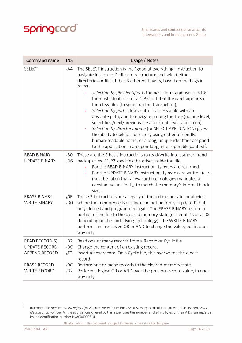
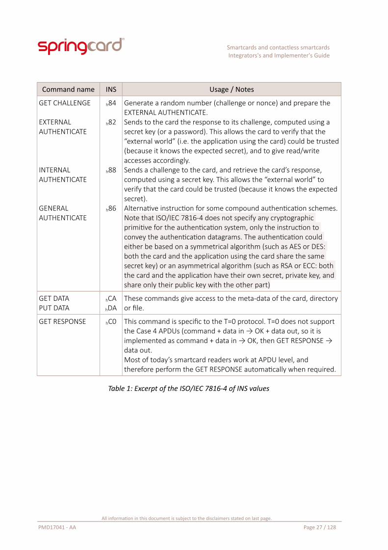
Table 1 starting next page provides an overview of the most frequently usedcommands, with a few explanations.
6 Possibly with the help of a dedicated smartcard, a SAM (secure access module), i.e. a ID-000 sized card whose unique role is to validate the transaction with the user’s cards, suppressing the need to store the security keys in the host software, which would make them vulnerable to hacking. Nowadays, SAM cards could be replaced by secure elements, or HSM (hardware security module). More about that in paragraphs 2.3.1 and 2.3.2.
All information in this document is subject to the disclaimers stated on last page.
PMD17041 - AA Page 25 / 128
Smartcards and contactless smartcardsIntegrators's and Implementer's Guide
Command name INS Usage / Notes
SELECT hA4 The SELECT instruction is the “good at everything” instruction to navigate in the card’s directory structure and select either directories or files. It has 3 different flavors, based on the flags in P1,P2:
• Selection by file identifier is the basic form and uses 2-B IDs for most situations, or a 1-B short ID if the card supports it for a few files (to speed up the transaction),
• Selection by path allows both to access a file with an absolute path, and to navigate among the tree (up one level, select first/next/previous file at current level, and so on),
• Selection by directory name (or SELECT APPLICATION) gives the ability to select a directory using either a friendly, human-readable name, or a long, unique identifier assigned to the application in an open-loop, inter-operable context7.
READ BINARYUPDATE BINARY
ERASE BINARYWRITE BINARY
hB0hD6
h0EhD0
These are the 2 basic instructions to read/write into standard (and backup) files. P1,P2 specifies the offset inside the file.
• For the READ BINARY instruction, LE bytes are returned.• For the UPDATE BINARY instruction, LC bytes are written (care
must be taken that a few card technologies mandates a constant values for LC, to match the memory’s internal block size).
These 2 instructions are a legacy of the old memory technologies, where the memory cells or block can not be freely “updated”, but only cleared and programmed again. The ERASE BINARY restore a portion of the file to the cleared memory state (either all 1s or all 0s depending on the underlying technology). The WRITE BINARY performs and exclusive OR or AND to change the value, but in one-way only.
READ RECORD(S)UPDATE RECORDAPPEND RECORD
ERASE RECORDWRITE RECORD
hB2hDChE2
h0ChD2
Read one or many records from a Record or Cyclic file.Change the content of an existing record.Insert a new record. On a Cyclic file, this overwrites the oldest record.Restore one or many records to the cleared-memory state.Perform a logical OR or AND over the previous record value, in one-way only.
7 Interoperable Application IDentifiers (AIDs) are covered by ISO/IEC 7816-5. Every card solution provider has its own issuer identification number. All the applications offered by this issuer uses this number as the first bytes of their AIDs. SpringCard’s issuer identification number is hA000000614.
All information in this document is subject to the disclaimers stated on last page.
PMD17041 - AA Page 26 / 128
Smartcards and contactless smartcardsIntegrators's and Implementer's Guide
Command name INS Usage / Notes
GET CHALLENGE
EXTERNAL AUTHENTICATE
INTERNAL AUTHENTICATE
GENERAL AUTHENTICATE
h84
h82
h88
h86
Generate a random number (challenge or nonce) and prepare the EXTERNAL AUTHENTICATE.Sends to the card the response to its challenge, computed using a secret key (or a password). This allows the card to verify that the “external world” (i.e. the application using the card) could be trusted(because it knows the expected secret), and to give read/write accesses accordingly.Sends a challenge to the card, and retrieve the card’s response, computed using a secret key. This allows the “external world” to verify that the card could be trusted (because it knows the expected secret).Alternative instruction for some compound authentication schemes.Note that ISO/IEC 7816-4 does not specify any cryptographic primitive for the authentication system, only the instruction to convey the authentication datagrams. The authentication could either be based on a symmetrical algorithm (such as AES or DES: both the card and the application using the card share the same secret key) or an asymmetrical algorithm (such as RSA or ECC: both the card and the application have their own secret, private key, and share only their public key with the other part)
GET DATAPUT DATA
hCAhDA
These commands give access to the meta-data of the card, directoryor file.
GET RESPONSE hC0 This command is specific to the T=0 protocol. T=0 does not support the Case 4 APDUs (command + data in → OK + data out, so it is implemented as command + data in → OK, then GET RESPONSE → data out.Most of today’s smartcard readers work at APDU level, and therefore perform the GET RESPONSE automatically when required.
Table 1: Excerpt of the ISO/IEC 7816-4 of INS values
All information in this document is subject to the disclaimers stated on last page.
PMD17041 - AA Page 27 / 128
Smartcards and contactless smartcardsIntegrators's and Implementer's Guide
It must be clearly stated that none of these commands is mandatory. The ISOstandard says to the developer of the card’s software “your select file instructionshould be INS=hA4”. It does neither say “your select file instruction MUST be...” nor“you MUST provide a select file instruction”. If the card developer wants to use adifferent INS for select file, he is allowed to do so. If the card has a single file andtherefore does not implement the select instruction, this is allowed as well.
Therefore, there’s no general way to “explore” a smartcard or to “read” its content.Without the card’s specification, without knowing the actual list of instructions (andtheir parameters) that the card supports, without knowing the actual list ofdirectories and files, and how are the data organised in them, there’s nothing onecan do reasonably with a smartcard.
More than that, smartcards are designed to protect their content by security systems(password protection or cryptographic authentication). If you do not know the key orthe password, you will not access the data, period8.
Do not start a smartcard project until you have the complete specification of thesmartcard you will be communicating with. Even resist the temptation to quote asoftware development effort before gathering all the information you will need tocomplete the project.
Complete specification means: the detailed documentation of the card’s instruction-set, the data model of the application, and the security model, and keys, to accessthem. The development team will also need to have tests cards. It is a good practiceto use a different key-set in the test cards than in the final cards.
Unless you are a manufacturer of readers (like SpringCard is), you don’t care of thecard’s hardware and low-level specification9.
Just make sure that the card is supported by the reader at protocol level (ISO/IEC7816-3 T=0 & T=1, or ISO/IEC 14443-4 “T=CL” for contactless cards), and everythingwill be fine.
8 This introductory document could not go into the technical details on how the card protects its content. Only a few words onthe subject: a secure card combines passive security (the memory is not a well ordered matrix, but a complex labyrinth where the bit-cell are dispatched here and there, so even an attacker with a physical access to the memory will not understand anything) and a lot of active countermeasures. Of course nothing is invulnerable, and a few old cards have been defeated by practical attacks, but this remain very rare. Most of the attacks remain purely theoretical, or at least too expensive to be reproduced out of a few well-equipped university labs.
9 Some cards use an operating system, such as JavaCard. This makes a strong difference for the developer of the application in the card, of course, but for the developer of the host application, and even for the reader itself, whether the card runs a code written in Java or in C or in assembler remains undistinguishable (at least until it comes to benchmarking the transaction speed).
All information in this document is subject to the disclaimers stated on last page.
PMD17041 - AA Page 28 / 128
Smartcards and contactless smartcardsIntegrators's and Implementer's Guide
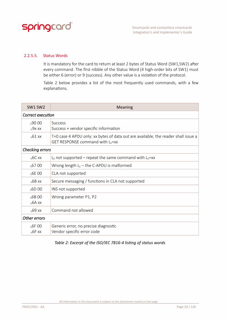
2.2.5.5. Status Words
It is mandatory for the card to return at least 2 bytes of Status Word (SW1,SW2) afterevery command. The first nibble of the Status Word (4 high-order bits of SW1) mustbe either 6 (error) or 9 (success). Any other value is a violation of the protocol.
Table 2 below provides a list of the most frequently used commands, with a fewexplanations.
SW1 SW2 Meaning
Correct execution
h90 00h9x xx
SuccessSuccess + vendor specific information
h61 xx T=0 case 4 APDU only: xx bytes of data out are available, the reader shall issue aGET RESPONSE command with LE=xx
Checking errors
h6C xx LE not supported – repeat the same command with LE=xx
h67 00 Wrong length LC – the C-APDU is malformed
h6E 00 CLA not supported
h68 xx Secure messaging / functions in CLA not supported
h6D 00 INS not supported
h6B 00h6A xx
Wrong parameter P1, P2
h69 xx Command not allowed
Other errors
h6F 00h6F xx
Generic error, no precise diagnosticVendor specific error code
Table 2: Excerpt of the ISO/IEC 7816-4 listing of status words
All information in this document is subject to the disclaimers stated on last page.
PMD17041 - AA Page 29 / 128
Smartcards and contactless smartcardsIntegrators's and Implementer's Guide
2.3. Variations around ISO/IEC 7816
2.3.1. SAM and HSM
A secure authentication module (SAM) is a ID-000 sized smartcard that plays only asingle role: store secret keys, and compute cryptograms. As all the other smartcards,a SAM is carefully designed to protect its secrets against all known attacks (and,ideally, against most future attacks).
Some transportation networks install a SAM at every gate to authenticate the user’s(contactless) smartcard very quickly; the gate’s performance is independent from thelatency of the network, and, more than that, the gate keeps working even in theevent when the network is down. Some electronic purse (e-payment) systems alsouse a SAM the merchant terminals for the same reasons.
A hardware security module (HSM) is a network appliance that provides the samefeatures and the same security level as a SAM card, but with a dramatically higherthroughput.
HSMs are typically used to authenticate the secure transactions (i.e. compute aCMAC, see 2.2.5.2) in large systems. They are also widely used in public keyinfrastructures (PKI) or to implement the secure communication layer (TLS, HTTPS) inperformance-critical servers or VPNs.
2.3.2. Secure elements and other “smartcard chips without card”
The last years have seen a fast development of complex, interconnected networks ofhigh-end technology artifacts, which can not be named “computers” anymorebecause they do not have a screen or a keyboard. Most of them don’t even have auser!
Smart-watches and other wearables, sensors connected to the Internet from yourown or from the streets of the smart-city where you live, counters and actuators ofthe smart-grid, the IoT (Internet of Things) is built on top of secure, trusted,machine-to-machine communication. Even the cheapest node in such a complex,interconnected system, must have its own secret keys and be tamper-proof;otherwise, the whole system is vulnerable to data leakage, denial or service attacks,injection of counterfeit data, and to many other unpleasant interactions.
The smartcard manufacturers have a strong experience in tamper-proof silicons andsecure software designs, which makes them key actors of the IoT market. All theyhave to do is offering their smartcard chips in the form of SMD components, evadingthe ISO-specified form-factor and contacts.
Such chips are named “secure companion chip”, “trusted platform coprocessor” ormore commonly “secure element”.
All information in this document is subject to the disclaimers stated on last page.
PMD17041 - AA Page 30 / 128
Smartcards and contactless smartcardsIntegrators's and Implementer's Guide
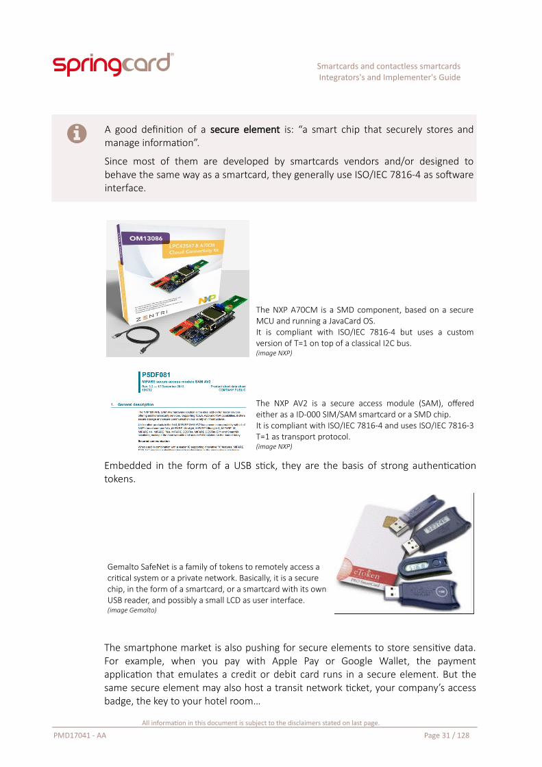
A good definition of a secure element is: “a smart chip that securely stores andmanage information”.
Since most of them are developed by smartcards vendors and/or designed tobehave the same way as a smartcard, they generally use ISO/IEC 7816-4 as softwareinterface.
The NXP A70CM is a SMD component, based on a secureMCU and running a JavaCard OS.It is compliant with ISO/IEC 7816-4 but uses a customversion of T=1 on top of a classical I2C bus.(image NXP)
The NXP AV2 is a secure access module (SAM), offeredeither as a ID-000 SIM/SAM smartcard or a SMD chip.It is compliant with ISO/IEC 7816-4 and uses ISO/IEC 7816-3T=1 as transport protocol.(image NXP)
Embedded in the form of a USB stick, they are the basis of strong authenticationtokens.
Gemalto SafeNet is a family of tokens to remotely access a critical system or a private network. Basically, it is a secure chip, in the form of a smartcard, or a smartcard with its own USB reader, and possibly a small LCD as user interface.(image Gemalto)
The smartphone market is also pushing for secure elements to store sensitive data.For example, when you pay with Apple Pay or Google Wallet, the paymentapplication that emulates a credit or debit card runs in a secure element. But thesame secure element may also host a transit network ticket, your company’s accessbadge, the key to your hotel room…
All information in this document is subject to the disclaimers stated on last page.
PMD17041 - AA Page 31 / 128
Smartcards and contactless smartcardsIntegrators's and Implementer's Guide
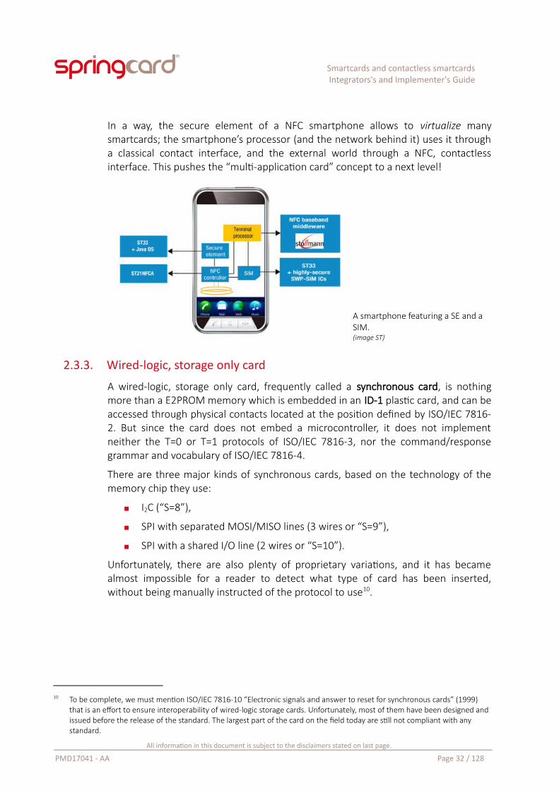
In a way, the secure element of a NFC smartphone allows to virtualize manysmartcards; the smartphone’s processor (and the network behind it) uses it througha classical contact interface, and the external world through a NFC, contactlessinterface. This pushes the “multi-application card” concept to a next level!
A smartphone featuring a SE and a SIM.(image ST)
2.3.3. Wired-logic, storage only card
A wired-logic, storage only card, frequently called a synchronous card, is nothingmore than a E2PROM memory which is embedded in an ID-1 plastic card, and can beaccessed through physical contacts located at the position defined by ISO/IEC 7816-2. But since the card does not embed a microcontroller, it does not implementneither the T=0 or T=1 protocols of ISO/IEC 7816-3, nor the command/responsegrammar and vocabulary of ISO/IEC 7816-4.
There are three major kinds of synchronous cards, based on the technology of thememory chip they use:
I2C (“S=8”),
SPI with separated MOSI/MISO lines (3 wires or “S=9”),
SPI with a shared I/O line (2 wires or “S=10”).
Unfortunately, there are also plenty of proprietary variations, and it has becamealmost impossible for a reader to detect what type of card has been inserted,without being manually instructed of the protocol to use10.
10 To be complete, we must mention ISO/IEC 7816-10 “Electronic signals and answer to reset for synchronous cards” (1999) that is an effort to ensure interoperability of wired-logic storage cards. Unfortunately, most of them have been designed and issued before the release of the standard. The largest part of the card on the field today are still not compliant with any standard.
All information in this document is subject to the disclaimers stated on last page.
PMD17041 - AA Page 32 / 128
Smartcards and contactless smartcardsIntegrators's and Implementer's Guide
Most today’s PC/SC smartcard readers do not support synchronous contact cards11.
Notably, SpringCard products do not (unless they are flashed with a customer-specific firmware).
2.3.4. Contactless cards
A contactless smartcard is a smartcard that uses inductive coupling to communicatewith its “reader”.
Inductive coupling is the technology behind NFC (Near Field Communication) andshort-range RFID (Radio Frequency Identification) in the 13.56 MHz (HF) radio band.
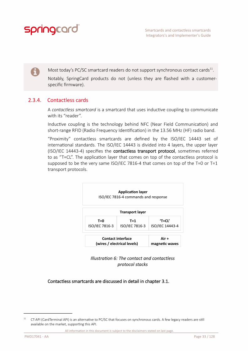
“Proximity” contactless smartcards are defined by the ISO/IEC 14443 set ofinternational standards. The ISO/IEC 14443 is divided into 4 layers, the upper layer(ISO/IEC 14443-4) specifies the contactless transport protocol, sometimes referredto as “T=CL”. The application layer that comes on top of the contactless protocol issupposed to be the very same ISO/IEC 7816-4 that comes on top of the T=0 or T=1transport protocols.
Illustration 6: The contact and contactlessprotocol stacks
Contactless smartcards are discussed in detail in chapter 3.1.
11 CT-API (CardTerminal API) is an alternative to PC/SC that focuses on synchronous cards. A few legacy readers are still available on the market, supporting this API.
All information in this document is subject to the disclaimers stated on last page.
PMD17041 - AA Page 33 / 128
Application layerISO/IEC 7816-4 commands and response
Transport layer
T=0ISO/IEC 7816-3
T=1ISO/IEC 7816-3
‘T=CL’ISO/IEC 14443-4
Contact interface(wires / electrical levels)
Air +magnetic waves
Smartcards and contactless smartcardsIntegrators's and Implementer's Guide
2.3.5. Wired-logic, storage only contactless cards
A lot of contactless cards on the market today are not “smartcards” but wired-logicmemories with an RF interface. The marketing gives them different names: RFIDlabels, NFC tags, contactless tickets… but they are all based on the same physicalprinciple: inductive coupling at 13.56MHz, and are all (more or less) compliant witheither ISO/IEC 14443 standard for proximity cards or ISO/IEC 15693 standard forvicinity (hand free) cards.
Wired-logic, storage only contactless cards are discussed in detail in chapter 3.2.
2.4. The coupling device or couplerNow that we know that a smartcard is a basically a (secure) microcontrollercommunicating with the external world through a (sort of) serial line, we must find abetter name than “reader” for the device that ensures the connectivity and givesaccess to the smartcard instructions.
Even if the term smartcard reader has been popularized by the PC/SC and CCIDspecifications, it does not reflect the technical reality, because a card’s instruction setopens lots more feature than just “reading” some data.
“Reading” a smartcard makes not more sense than “reading” a remote web server,or “reading” a SQL database; you do not “read” a raw memory; your applicationsends some commands to get authenticated, sends other commands to explore a filesystem, sends commands to insert / update / delete the data… and read it, of course,but not only.
Therefore, the device in which the smartcard is inserted plays the role of a pass-through gateway between a software running in the host computer (or hostterminal) and the software running inside the card’s microcontroller.
This pass-through gateway translates commands coming from the host applicationthrough either USB, Serial, Ethernet, or any other computer interconnectiontechnology, into electrical signals that are compliant with the asynchronous, half-duplex serial T=0 or T=1 transport protocol. But this gateway does not add anyprocessing logic; its position is to couple the smartcard with the computer.
As a consequence, the standard name, as defined by ISO/IEC 7816, is coupling device(CD) or simply coupler.
Contactless couplers are in turn named proximity coupling device (PCD) by ISO/IEC14443 or vicinity coupling device (VCD) by ISO/IEC 15693.
All information in this document is subject to the disclaimers stated on last page.
PMD17041 - AA Page 34 / 128
Smartcards and contactless smartcardsIntegrators's and Implementer's Guide
3. Contactless cards, RFID, NFC – concepts and standards
3.1. ‘Proximity’ contactless smartcards
3.1.1. Basics
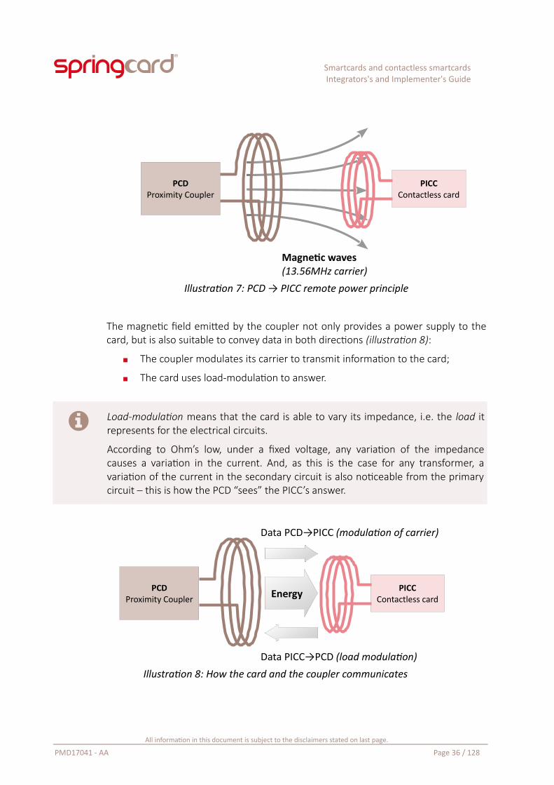
A contactless smartcard is a smartcard that uses inductive coupling to communicatewith its coupler. Inductive coupling is the principle behind electric transformers: aprimary coil is powered by a AC voltage and creates a magnetic field. The magneticfield induces a current in the secondary coil.
In the case of contactless cards, the primary coil is driven by a sinusoidal voltage at13.56 MHz, and hence creates a magnetic field with a 13.56 MHz carrier frequency(HF radio band). This magnetic field is not constrained in a confined volume, as itwould be the case in an actual transformer. Instead, the field floods virtually freelywithin a part of the open air, limited only by the directivity of the coil and the (fast)decrease of the magnetic waves.
This coil and its driving circuit, forming the primary of a virtual transformer, is namedthe Proximity Coupling Device (PCD).
When a (mobile) secondary coil is moved into the part of the space where the PCD’sfield floods – say, comes in proximity to the primary circuit (illustration 7) – thetransformer, once virtual, now becomes real. The flow of the magnetic field throughthe secondary coil provides electrical power to a secondary, passive, circuit.
As you may have guessed, this mobile part of the transformer, made of a coil and ofan electronic circuit (or a chip) is the Proximity Integrated Circuit Card (PICC).
All information in this document is subject to the disclaimers stated on last page.
PMD17041 - AA Page 35 / 128
Smartcards and contactless smartcardsIntegrators's and Implementer's Guide
Illustration 7: PCD → PICC remote power principle
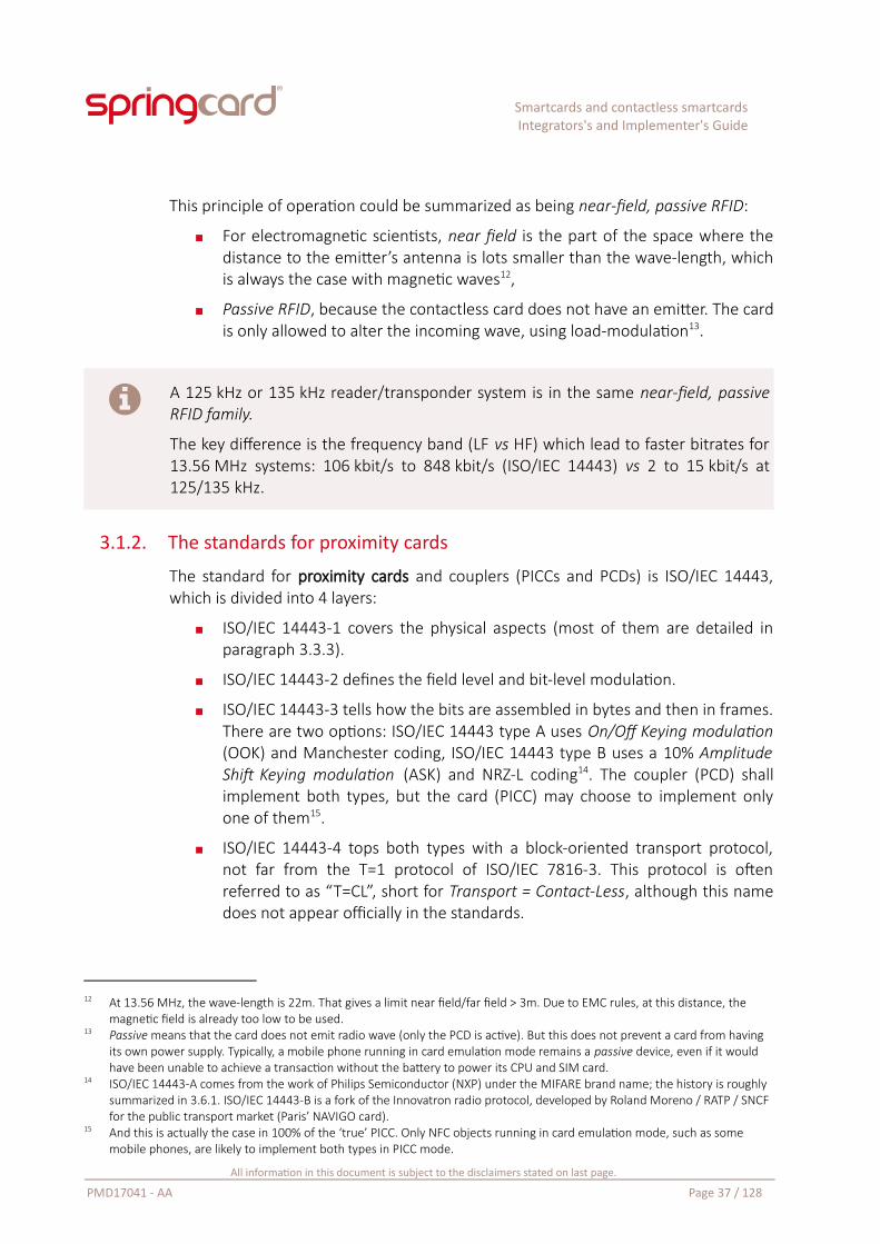
The magnetic field emitted by the coupler not only provides a power supply to thecard, but is also suitable to convey data in both directions (illustration 8):
The coupler modulates its carrier to transmit information to the card;
The card uses load-modulation to answer.
Load-modulation means that the card is able to vary its impedance, i.e. the load itrepresents for the electrical circuits.
According to Ohm’s low, under a fixed voltage, any variation of the impedancecauses a variation in the current. And, as this is the case for any transformer, avariation of the current in the secondary circuit is also noticeable from the primarycircuit – this is how the PCD “sees” the PICC’s answer.
Illustration 8: How the card and the coupler communicates
All information in this document is subject to the disclaimers stated on last page.
PMD17041 - AA Page 36 / 128
PCDProximity Coupler
PICCContactless cardEnergy
Data PCD→PICC (modulation of carrier)
Data PICC→PCD (load modulation)
PCDProximity Coupler
PICCContactless card
Magnetic waves(13.56MHz carrier)
Smartcards and contactless smartcardsIntegrators's and Implementer's Guide
This principle of operation could be summarized as being near-field, passive RFID:
For electromagnetic scientists, near field is the part of the space where thedistance to the emitter’s antenna is lots smaller than the wave-length, whichis always the case with magnetic waves12,
Passive RFID, because the contactless card does not have an emitter. The cardis only allowed to alter the incoming wave, using load-modulation13.
A 125 kHz or 135 kHz reader/transponder system is in the same near-field, passiveRFID family.
The key difference is the frequency band (LF vs HF) which lead to faster bitrates for13.56 MHz systems: 106 kbit/s to 848 kbit/s (ISO/IEC 14443) vs 2 to 15 kbit/s at125/135 kHz.
3.1.2. The standards for proximity cards
The standard for proximity cards and couplers (PICCs and PCDs) is ISO/IEC 14443,which is divided into 4 layers:
ISO/IEC 14443-1 covers the physical aspects (most of them are detailed inparagraph 3.3.3).
ISO/IEC 14443-2 defines the field level and bit-level modulation.
ISO/IEC 14443-3 tells how the bits are assembled in bytes and then in frames.There are two options: ISO/IEC 14443 type A uses On/Off Keying modulation(OOK) and Manchester coding, ISO/IEC 14443 type B uses a 10% AmplitudeShift Keying modulation (ASK) and NRZ-L coding14. The coupler (PCD) shallimplement both types, but the card (PICC) may choose to implement onlyone of them15.
ISO/IEC 14443-4 tops both types with a block-oriented transport protocol,not far from the T=1 protocol of ISO/IEC 7816-3. This protocol is oftenreferred to as “T=CL”, short for Transport = Contact-Less, although this namedoes not appear officially in the standards.
12 At 13.56 MHz, the wave-length is 22m. That gives a limit near field/far field > 3m. Due to EMC rules, at this distance, the magnetic field is already too low to be used.
13 Passive means that the card does not emit radio wave (only the PCD is active). But this does not prevent a card from having its own power supply. Typically, a mobile phone running in card emulation mode remains a passive device, even if it would have been unable to achieve a transaction without the battery to power its CPU and SIM card.
14 ISO/IEC 14443-A comes from the work of Philips Semiconductor (NXP) under the MIFARE brand name; the history is roughly summarized in 3.6.1. ISO/IEC 14443-B is a fork of the Innovatron radio protocol, developed by Roland Moreno / RATP / SNCF for the public transport market (Paris’ NAVIGO card).
15 And this is actually the case in 100% of the ‘true’ PICC. Only NFC objects running in card emulation mode, such as some mobile phones, are likely to implement both types in PICC mode.
All information in this document is subject to the disclaimers stated on last page.
PMD17041 - AA Page 37 / 128
Smartcards and contactless smartcardsIntegrators's and Implementer's Guide
Vicinity cards, and the difference between Proximity and Vicinity, are the subject ofparagraph 3.4.
3.1.3. Polling
In a contact coupler, a physical switch tells the coupler when a card has beeninserted into position and is ready for operation (at least may be ready – it could be adumb plastic card, or it could have been inserted upside down…). But a contactlesscoupler has no equivalent way to be notified when a card arrives or leaves. There isno choice for the contactless coupler but to broadcast repeatedly a message like “isthere someone here?”, in the hope that a card would be near enough to answer.
A PCD supporting both types A & B of ISO/IEC 14443 broadcasts REQA (Request A) orWUPA (WakeUp A) and waits for a few milliseconds, in the hope that a type A cardmay answer in the opened time-window. If there is no answer, the PCD broadcastsREQB (Request B) or WUPB (WakeUp B), and opens another time-window. If there isstill no answer, the PCD tries again with type A, and so on.
This endless process is called the coupler’s polling loop. In a multi-technologycoupler, other protocols (ISO/IEC 15693, FeliCa, proprietary...) may also be part ofthe loop.
When a card is in position for communication, the card answers to eitherREQA/WUPA or REQB/WUPB by ATQA (Answer To Query A) or ATQB (Answer ToQuery B) during the time-window opened by the coupler. The coupler then reportsthe presence of the card to the host computer, and an application running in thehost computer may start using the card.
All information in this document is subject to the disclaimers stated on last page.
PMD17041 - AA Page 38 / 128
Smartcards and contactless smartcardsIntegrators's and Implementer's Guide
3.1.4. Anticollision
Now let’s consider the case of two or more contactless cards entering the PCD’s RFfield in the same time.
If all the cards use different protocols, the coupler “sees” one answer to everyrequest frame. But if at least two cards use the same protocol, their answers collidein the same time-window. The coupler is then unable to discriminate among the twoanswers. The PCD must then run a collision-resolution algorithm – the anticollisionloop – to enumerate all the cards.
ISO/IEC 14443 type A features a deterministic anticollision method, which means thatall cards could be enumerated in a deterministic, reliable sequence.
ISO/IEC 14443 type B features a probabilistic anticollision method, where the cardsgenerate random numbers to answer in random time-slots. This method is globallyslower, and can not guarantee that all cards will eventually be enumerated.
3.1.5. Single card approach
But is it really interesting for a PCD to enumerate all the nearby PICCs? In most real-world applications, the answer is simply no.
Of course, when the PCD is part on a warehouse inventory system, or when there isby design a high probability of collisions (this is for instance the case for electronicpassports with added electronic visa labels), there is no choice but to enumerate allthe PICCs present, and let the top-level application decide the one(s) it wants toprocess.
On the other hand, a point of sale terminal (POS) must be able to know preciselywho is willing to pay for a service or a good. If you put in front of the POS’ coupler awallet containing two debit or credit cards, the POS has no way to decide which oneshould be charged. Therefore, the POS cancels the transaction and prompts you toplace one card, and only one, in front of its antenna. Therefore, the POS couplerdoes not have to implement any kind of anticollision – all it has to do is reportingthat a collision has occurred.
And the same applies for a PC/SC contactless coupler. PC/SC has been primarilydesigned for contact smartcards. There is no chance that two smartcards could everbe introduced – and powered – in a single contact slot. Therefore, the PC/SCinfrastructure relies on the paradigm “one coupler = one card”.
A PC/SC-compliant PCD may know that there are two (or more) cards there, but thePC/SC middleware and the host applications ‘sees’ only one card at once.
All information in this document is subject to the disclaimers stated on last page.
PMD17041 - AA Page 39 / 128
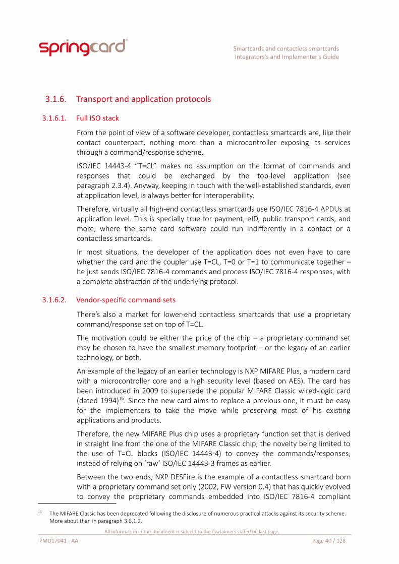
Smartcards and contactless smartcardsIntegrators's and Implementer's Guide
3.1.6. Transport and application protocols
3.1.6.1. Full ISO stack
From the point of view of a software developer, contactless smartcards are, like theircontact counterpart, nothing more than a microcontroller exposing its servicesthrough a command/response scheme.
ISO/IEC 14443-4 “T=CL” makes no assumption on the format of commands andresponses that could be exchanged by the top-level application (seeparagraph 2.3.4). Anyway, keeping in touch with the well-established standards, evenat application level, is always better for interoperability.
Therefore, virtually all high-end contactless smartcards use ISO/IEC 7816-4 APDUs atapplication level. This is specially true for payment, eID, public transport cards, andmore, where the same card software could run indifferently in a contact or acontactless smartcards.
In most situations, the developer of the application does not even have to carewhether the card and the coupler use T=CL, T=0 or T=1 to communicate together –he just sends ISO/IEC 7816-4 commands and process ISO/IEC 7816-4 responses, witha complete abstraction of the underlying protocol.
3.1.6.2. Vendor-specific command sets
There’s also a market for lower-end contactless smartcards that use a proprietarycommand/response set on top of T=CL.
The motivation could be either the price of the chip – a proprietary command setmay be chosen to have the smallest memory footprint – or the legacy of an earliertechnology, or both.
An example of the legacy of an earlier technology is NXP MIFARE Plus, a modern cardwith a microcontroller core and a high security level (based on AES). The card hasbeen introduced in 2009 to supersede the popular MIFARE Classic wired-logic card(dated 1994)16. Since the new card aims to replace a previous one, it must be easyfor the implementers to take the move while preserving most of his existingapplications and products.
Therefore, the new MIFARE Plus chip uses a proprietary function set that is derivedin straight line from the one of the MIFARE Classic chip, the novelty being limited tothe use of T=CL blocks (ISO/IEC 14443-4) to convey the commands/responses,instead of relying on ‘raw’ ISO/IEC 14443-3 frames as earlier.
Between the two ends, NXP DESFire is the example of a contactless smartcard bornwith a proprietary command set only (2002, FW version 0.4) that has quickly evolvedto convey the proprietary commands embedded into ISO/IEC 7816-4 compliant
16 The MIFARE Classic has been deprecated following the disclosure of numerous practical attacks against its security scheme. More about than in paragraph 3.6.1.2.
All information in this document is subject to the disclaimers stated on last page.
PMD17041 - AA Page 40 / 128
Smartcards and contactless smartcardsIntegrators's and Implementer's Guide
messages (DESFire EV0, 2004, FW version 0.6) before eventually plunging into theISO/IEC 7816-4 command set (DESFire EV1, 2008), at least partially17.
3.1.7. Contactless smartcards and PC/SC
The ISO/IEC 14443-4 “T=CL” protocol is very close to the T=1 contact protocol, so thecontactless smartcards are operated as if they were T=1 cards. It makes no differencefrom the application’s point of view.
In PC/SC, the card must also have an ATR. The PC/SC standard therefore specifieshow the contactless coupler build a virtual ATR from the contactless card’s ISO/IEC14443-4 meta-data. This is detailed in paragraph 6.4.1.
3.1.8. Contactless only, dual, two-chip cards
Most contactless cards are ‘contactless only’, meaning that the chip’s only interface isits antenna and a RF ‘modem’. Some cards feature both contact and contactlessinterfaces.
This is typically the case of corporate badges: on the one hand, the access-controlreaders at the entrance of the building or rooms use the card’s contactless interface.A private e-purse may also be handled this way by the ATMs or at the company’srestaurant. On the other hand, the IT-related services – session opening on thedesktop or laptop, encryption of the hard disks, single-sign-on (SSO) on the Intranetor corporate applications, digital signature – use the card through its contactinterface.
Most credit or debit cards delivered today by the banking industry also feature twointerfaces: contactless payment is enabled for low amounts and does not require theuser’s PIN; for larger amounts, the card (or the terminal) enforces contact operationand PIN entry.
But there’s a slight difference here: in the case of a credit or a debit card, a singlechip provides the same service (payment) through the two interfaces. In the case ofthe corporate badge, there is no evidence that the contactless world (access control,e-purse) and the contact world (IT) have any data to share.
More than that, opening security-sensitive corporate processes (like digital signatureor SSO), through a contactless interface, could be seen as a potential security breach.As a consequence, a lot of contact+contactless cards are not actually based on dual-access chips, but embed two chips (one for contact, one for contactless) that havenothing in common.
17 DESFire EV1 provides ISO/IEC 7816-4 commands to handle the data (SELECT, READ, UPDATE) but not much more. Formattingthe card or using efficiently its various security features implies going back to the proprietary command set. The new DESFireEV2 (2016) goes one step further with new ISO/IEC 7816-4 commands added.
All information in this document is subject to the disclaimers stated on last page.
PMD17041 - AA Page 41 / 128
Smartcards and contactless smartcardsIntegrators's and Implementer's Guide
Illustration 9: A first-generation's dual-access card, featuring a coppercoil welded behind the ISO/IEC 7816 module
3.2. Wired-logic proximity contactless cardsAs this is the case in the contact world with synchronous cards, there are plenty ofcontactless cards that does not embed a processor. They could be seen as a rawmemory storage, with some kind of digital-logic (or an ASIC) exposing a very limitedset of functions to read / write data, and maybe to offer basic security features.
3.2.1. Support of wired-logic cards by standard PCDs
In the world of contact cards, the standards have appeared (long) after mostsynchronous cards have been designed – and released.
But in the world of contactless cards and RFID, the ISO/IEC 14443 standard has beenwritten early in the process, and is, by design, very close to the proprietary systemthat was leader of the market at the time (MIFARE)18.
As a consequence, most wired-logic contactless cards available today rely on ISO/IEC14443-3 (or at least ISO/IEC 14443-2), and it’s not a challenge for a PCD that iscompliant with the standard to support them as well.
There are 2 noticeable exceptions: 2 companies that had already developed theirown contactless protocols before the adoption of ISO/IEC 14443 in 2001, and thatdidn’t take the move to the standard protocol since then.
The 1st of them is Sony; the Sony FeliCa family of cards is still using a Japaneseprotocol (JIS X 6319-4) that has been declined by the ISO/IEC 14443 committee. ButSony has managed to push this protocol into NFCIP-1 (ISO/IEC 18092) in 2003, and
18 For more information regarding the MIFARE family, read 3.6.1.
All information in this document is subject to the disclaimers stated on last page.
PMD17041 - AA Page 42 / 128
Smartcards and contactless smartcardsIntegrators's and Implementer's Guide
to have the FeliCa cards adopted by NFC Forum as Type 3 Tags. Therefore, thisprotocol is now supported by most mainstream couplers, at least partially.
The 2nd is LEGIC. The LEGIC Prime is a family of cards that rely on a proprietary,undisclosed protocol. But at last, the new generation of cards (LEGIC Advant) isgoing full ISO.
SpringCard contactless couplers support a large number of wired-logic chips.Anyway, some hardware are (by design) unable to support some of them, and oldfirmware versions may provide only a small part of the features offered by an up-to-date firmware. Always refer to each product’s datasheet to know for sure whichtechnologies are actually supported by the device you intend to use.
3.2.2. Support of wired-logic contactless cards under PC/SC
The PC/SC standard specifies 4 commands, taken from the ISO/IEC 7816-4 standard,to work with wired-logic contactless cards.
These commands are not forwarded to the card, since a wired-logic card would notsupport them. They are processed, or interpreted, by the coupler’s microcontroller,that is responsible for translating them into the equivalent commands in the card’sspecific function set and protocol.
The 4 commands are:
GET DATA (INS=hCA) is used to retrieve the card’s protocol-level identifier(UID/PUPI/serial number/random ID),
READ BINARY (INS=hB0) to read a data block,
UPDATE BINARY (INS=hD6) to write a data block,
GENERAL AUTHENTICATE (INS=h86) to get authenticated onto the card, if theauthentication algorithm and keys are implemented in the coupler itself, notin the host application. This is only the case for the CRYPTO1 algorithm ofMIFARE Classic19.
These commands, and the other commands exposed by the embedded APDUProcessor, are documented in paragraph 6.6.
In PC/SC every card must also have an ATR. The PC/SC standard therefore specifieshow the contactless coupler build a virtual ATR from the wired-logic contactlesscards protocol information. The ATR’s historical bytes exposes the card’s technicaldata (active protocol, card family). This is detailed in paragraph 6.4.1.
19 CRYPTO1 is a proprietary algorithm that is embedded only in NXP reader chips (and cards, of course). Therefore the host application is not able to implement the authentication itself, as it would be the case for other card technologies, and must rely on the reader’s internal logic to do the job, hence the GENERAL AUTHENTICATE instruction.
All information in this document is subject to the disclaimers stated on last page.
PMD17041 - AA Page 43 / 128
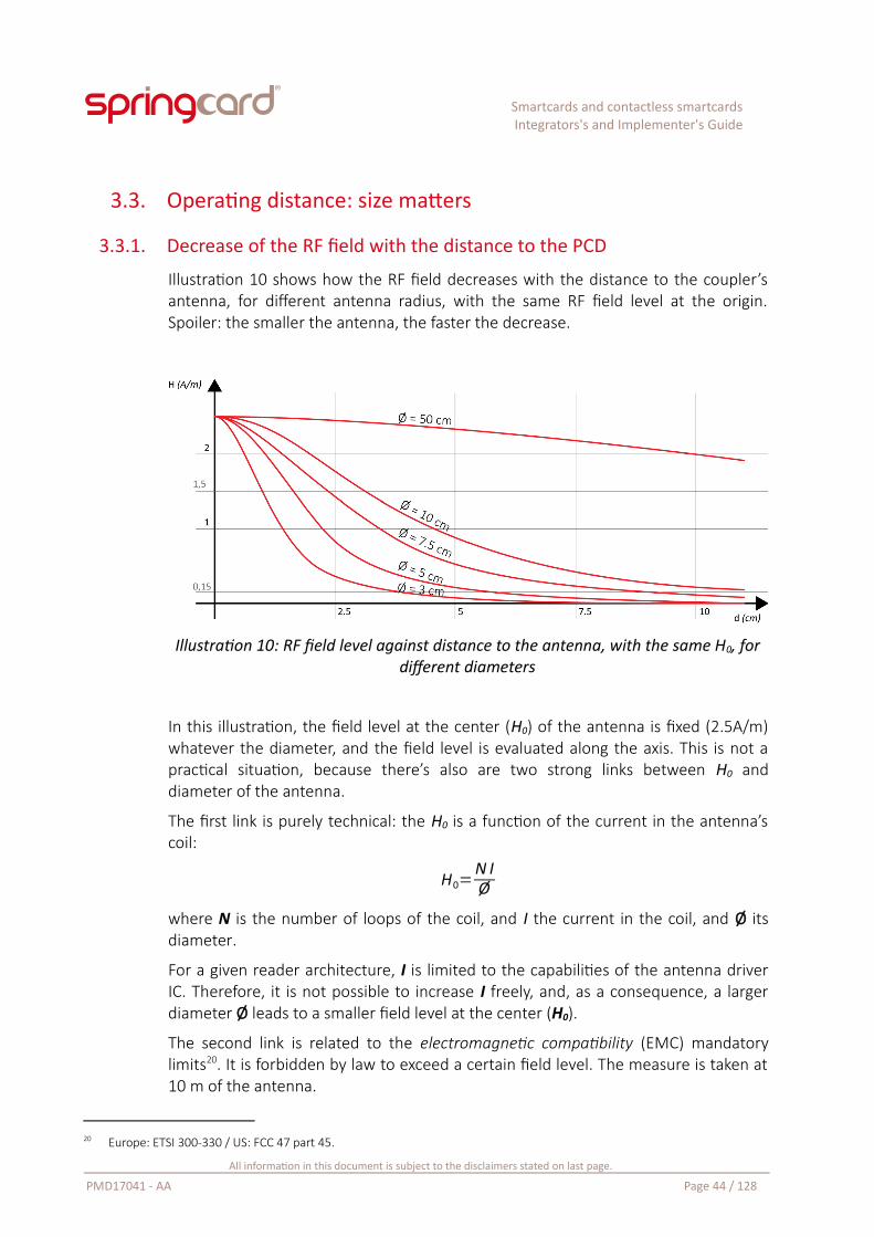
Smartcards and contactless smartcardsIntegrators's and Implementer's Guide
3.3. Operating distance: size matters
3.3.1. Decrease of the RF field with the distance to the PCD
Illustration 10 shows how the RF field decreases with the distance to the coupler’santenna, for different antenna radius, with the same RF field level at the origin.Spoiler: the smaller the antenna, the faster the decrease.
Illustration 10: RF field level against distance to the antenna, with the same H0, fordifferent diameters
In this illustration, the field level at the center (H0) of the antenna is fixed (2.5A/m)whatever the diameter, and the field level is evaluated along the axis. This is not apractical situation, because there’s also are two strong links between H0 anddiameter of the antenna.
The first link is purely technical: the H0 is a function of the current in the antenna’scoil:
H0=N IØ
where N is the number of loops of the coil, and I the current in the coil, and Ø itsdiameter.
For a given reader architecture, I is limited to the capabilities of the antenna driverIC. Therefore, it is not possible to increase I freely, and, as a consequence, a largerdiameter Ø leads to a smaller field level at the center (H0).
The second link is related to the electromagnetic compatibility (EMC) mandatorylimits20. It is forbidden by law to exceed a certain field level. The measure is taken at10 m of the antenna.
20 Europe: ETSI 300-330 / US: FCC 47 part 45.
All information in this document is subject to the disclaimers stated on last page.
PMD17041 - AA Page 44 / 128
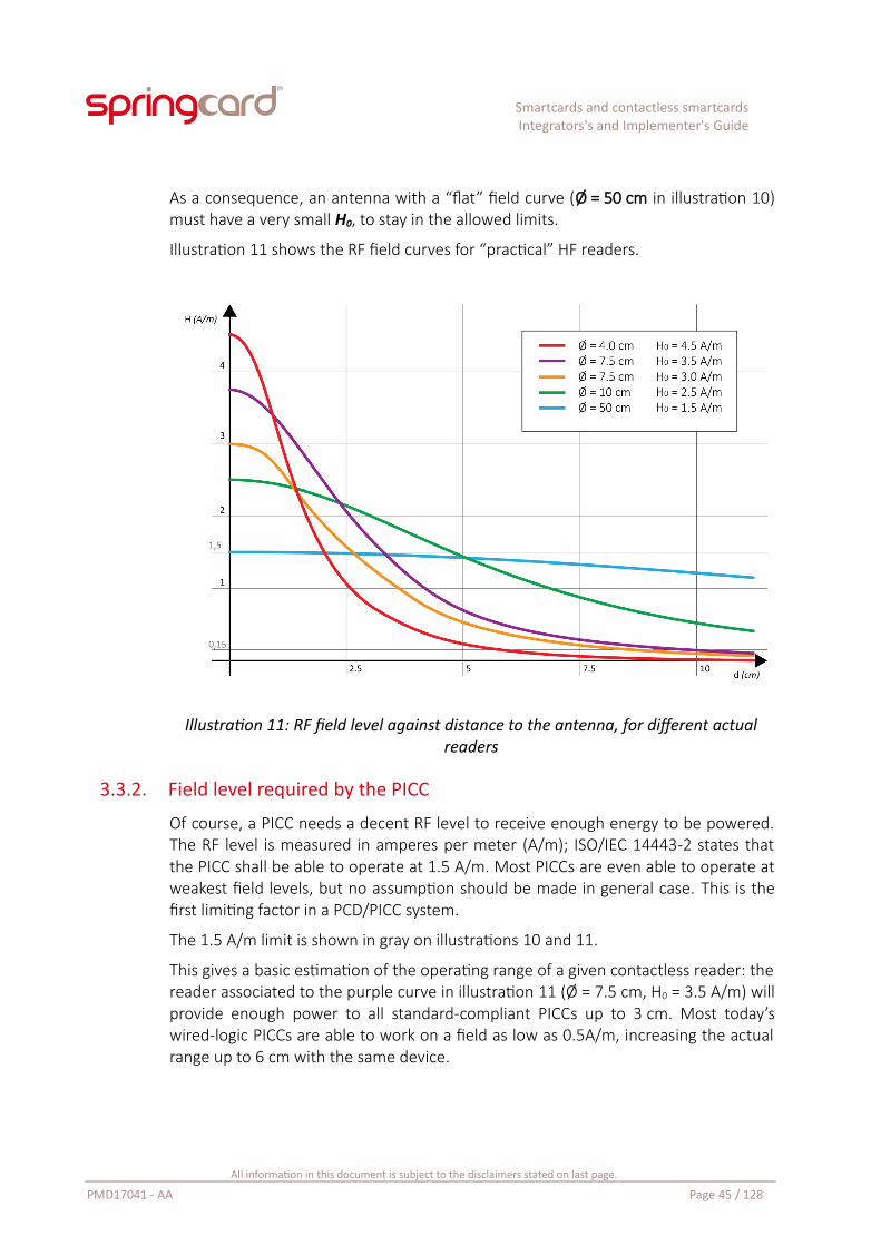
Smartcards and contactless smartcardsIntegrators's and Implementer's Guide
As a consequence, an antenna with a “flat” field curve (Ø = 50 cm in illustration 10)must have a very small H0, to stay in the allowed limits.
Illustration 11 shows the RF field curves for “practical” HF readers.
Illustration 11: RF field level against distance to the antenna, for different actualreaders
3.3.2. Field level required by the PICC
Of course, a PICC needs a decent RF level to receive enough energy to be powered.The RF level is measured in amperes per meter (A/m); ISO/IEC 14443-2 states thatthe PICC shall be able to operate at 1.5 A/m. Most PICCs are even able to operate atweakest field levels, but no assumption should be made in general case. This is thefirst limiting factor in a PCD/PICC system.
The 1.5 A/m limit is shown in gray on illustrations 10 and 11.
This gives a basic estimation of the operating range of a given contactless reader: thereader associated to the purple curve in illustration 11 (Ø = 7.5 cm, H0 = 3.5 A/m) willprovide enough power to all standard-compliant PICCs up to 3 cm. Most today’swired-logic PICCs are able to work on a field as low as 0.5A/m, increasing the actualrange up to 6 cm with the same device.
All information in this document is subject to the disclaimers stated on last page.
PMD17041 - AA Page 45 / 128
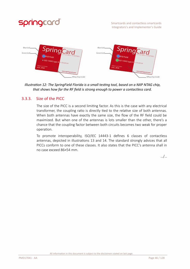
Smartcards and contactless smartcardsIntegrators's and Implementer's Guide
Illustration 12: The SpringField Florida is a small testing tool, based on a NXP NTAG chip,that shows how far the RF field is strong enough to power a contactless card.
3.3.3. Size of the PICC
The size of the PICC is a second limiting factor. As this is the case with any electricaltransformer, the coupling ratio is directly tied to the relative size of both antennas.When both antennas have exactly the same size, the flow of the RF field could bemaximized. But when one of the antennas is lots smaller than the other, there’s achance that the coupling factor between both circuits becomes two weak for properoperation.
To promote interoperability, ISO/IEC 14443-1 defines 6 classes of contactlessantennas, depicted in illustrations 13 and 14. The standard strongly advices that allPICCs conform to one of these classes. It also states that the PICC’s antenna shall inno case exceed 86×54 mm.
…/…
All information in this document is subject to the disclaimers stated on last page.
PMD17041 - AA Page 46 / 128
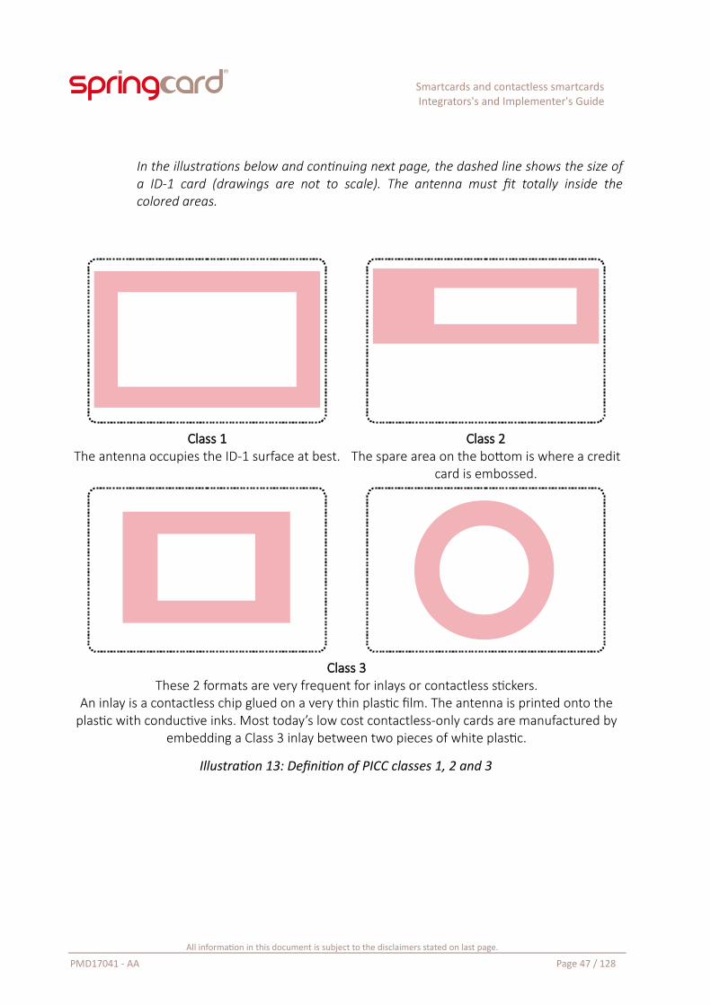
Smartcards and contactless smartcardsIntegrators's and Implementer's Guide
In the illustrations below and continuing next page, the dashed line shows the size ofa ID-1 card (drawings are not to scale). The antenna must fit totally inside thecolored areas.
Class 1The antenna occupies the ID-1 surface at best.
Class 2The spare area on the bottom is where a credit
card is embossed.
Class 3These 2 formats are very frequent for inlays or contactless stickers.
An inlay is a contactless chip glued on a very thin plastic film. The antenna is printed onto theplastic with conductive inks. Most today’s low cost contactless-only cards are manufactured by
embedding a Class 3 inlay between two pieces of white plastic.
Illustration 13: Definition of PICC classes 1, 2 and 3
All information in this document is subject to the disclaimers stated on last page.
PMD17041 - AA Page 47 / 128
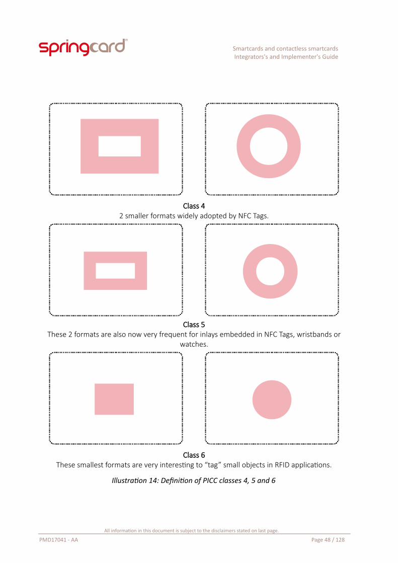
Smartcards and contactless smartcardsIntegrators's and Implementer's Guide
Class 42 smaller formats widely adopted by NFC Tags.
Class 5These 2 formats are also now very frequent for inlays embedded in NFC Tags, wristbands or
watches.
Class 6These smallest formats are very interesting to “tag” small objects in RFID applications.
Illustration 14: Definition of PICC classes 4, 5 and 6
All information in this document is subject to the disclaimers stated on last page.
PMD17041 - AA Page 48 / 128
Smartcards and contactless smartcardsIntegrators's and Implementer's Guide
3.3.4. Which classes a coupler has to support?
According to ISO/IEC 14443-1, only the support of Classes 1, 2 and 3 is mandatoryfor all contactless couplers (PCDs).
All out-of-shell SpringCard contactless couplers support classes 1 to 521.
Last generation couplers do also support class 6 with a decent operating distance (atleast 1.5 to 2 cm). Customers shall be aware that couplers of earlier generations maybe unable to operate class 6 cards at more than 0.5 cm – which may be consideredas too short for a satisfying user experience.
The standard does not claims that a PICC outside of the 6 classes should not orcould not be supported, but the operation of a compliant PCD could only beguaranteed with PICCs belonging to one of the 6 classes.
3.3.5. Actual operating distance
“What is the operating distance of this coupler” is the most frequent question everheard by a manufacturer of contactless couplers.
And it is also the question one couldn’t answer, because the answers comes not onlyfrom the coupler, but also from a lot of parameters coming the card itself:
The size of its antenna, of course,
How much power it requires from the RF field,
How its RF circuit (antenna + matching capacitor) has been designed.
As a rule of thumb, you may consider that with a decently manufacturer wired-logicclass 1 card, the maximum operating distance is something between 150 and 200%of the diameter (or diagonal) of the coupler’s antenna22.
A contactless smartcard having the same format, but with a microcontroller thatrequires a little more power than the memory-only chip, will behave correctly onlyup to 125 or 150% of the diameter (or diagonal) of the coupler’s antenna, at least atslow speed (106 kbit/s). At a higher speed, the chip requires more power, and thesignal over noise ration is decreased, so the operating distance decreases when thebitrate increases.
It may be noticed that performances are generally a little better or at least morerepeatable in ISO/IEC 14443-A than in ISO/IEC 14443-B, due to a more robustmodulation scheme.
21 Some customer-specific products have been especially created to support very small tags (smaller than class 6) and are by design unable to power cards that are larger than class 6. But this devices are not made available to other customers.
22 This is a little more than we have announced at first in 3.3.1, because most wired-logic cards may start running on a field as low as 0.8 A/m (instead of the 1.5 A/m limit considered in first approach).
All information in this document is subject to the disclaimers stated on last page.
PMD17041 - AA Page 49 / 128
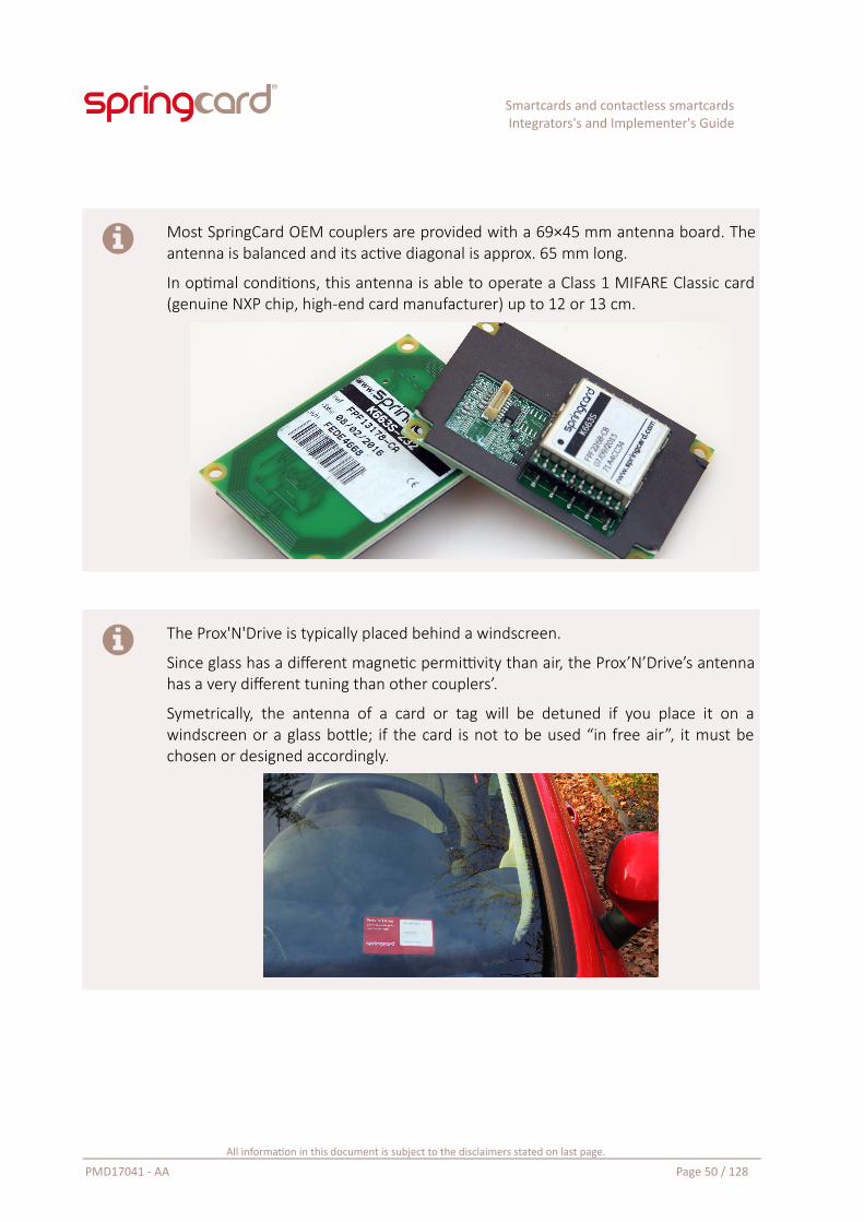
Smartcards and contactless smartcardsIntegrators's and Implementer's Guide
Most SpringCard OEM couplers are provided with a 69×45 mm antenna board. Theantenna is balanced and its active diagonal is approx. 65 mm long.
In optimal conditions, this antenna is able to operate a Class 1 MIFARE Classic card(genuine NXP chip, high-end card manufacturer) up to 12 or 13 cm.
The Prox'N'Drive is typically placed behind a windscreen.
Since glass has a different magnetic permittivity than air, the Prox’N’Drive’s antennahas a very different tuning than other couplers’.
Symetrically, the antenna of a card or tag will be detuned if you place it on awindscreen or a glass bottle; if the card is not to be used “in free air”, it must bechosen or designed accordingly.
All information in this document is subject to the disclaimers stated on last page.
PMD17041 - AA Page 50 / 128
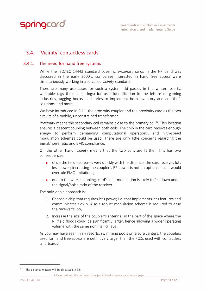
Smartcards and contactless smartcardsIntegrators's and Implementer's Guide
3.4. ‘Vicinity’ contactless cards
3.4.1. The need for hand free systems
While the ISO/IEC 14443 standard covering proximity cards in the HF band wasdiscussed in the early 2000’s, companies interested in hand free access weresimultaneously working in a so-called vicinity standard.
There are many use cases for such a system: ski passes in the winter resorts,wearable tags (bracelets, rings) for user identification in the leisure or gamingindustries, tagging books in libraries to implement both inventory and anti-theftsolutions, and more.
We have introduced in 3.1.1 the proximity coupler and the proximity card as the twocircuits of a mobile, unconstrained transformer.
Proximity means the secondary coil remains close to the primary coil23. This locationensures a descent coupling between both coils. The chip in the card receives enoughenergy to perform demanding computational operations, and high-speedmodulation schemes could be used. There are only little concerns regarding thesignal/noise ratio and EMC compliance.
On the other hand, vicinity means that the two coils are farther. This has twoconsequences:
since the field decreases very quickly with the distance, the card receives lotsless power; increasing the coupler’s RF power is not an option since it wouldoverrule EMC limitations,
due to the worse coupling, card’s load-modulation is likely to fell down underthe signal/noise ratio of the receiver.
The only viable approach is:
1. Choose a chip that requires less power, i.e. that implements less features andcommunicates slowly. Also a robust modulation scheme is required to easethe receiver’s job,
2. Increase the size of the coupler’s antenna, so the part of the space where theRF field floods could be significantly larger, hence allowing a wider operatingvolume with the same nominal RF level.
As you may have seen in ski resorts, swimming pools or leisure centers, the couplersused for hand free access are definitively larger than the PCDs used with contactlesssmartcards!
23 The distance matters will be discussed in 3.5
All information in this document is subject to the disclaimers stated on last page.
PMD17041 - AA Page 51 / 128
Smartcards and contactless smartcardsIntegrators's and Implementer's Guide
3.4.2. The standards
The result of this effort on hand free systems is the ISO/IEC 15693 standard,introducing the concept of vicinity integrated circuit card (VICC) and of coursevicinity coupling device (VCD).
3.4.2.1. Size
As it is the case for ISO/IEC 14443-1, ISO/IEC 15693-1 states that the VICC’s antennashall in no case exceed 86×54 mm. There is no other explicit size constraint or evenadvice for VICCs. Anyway, the VCD test bench uses only ID-1 VICCs, and that impliesthat the behavior with a VICC smaller or bigger than ID-1 could not be tested usingthe standard test tools.
3.4.2.2. Field level
The field level is defined in ISO/IEC 15693-2. The VICC must be able to operate on afield as low as 0.15 A/m.
Let’s go back to illustration 11 on page 45: we have written then that PCBcorresponding to the purple curve (Ø = 7.5 cm, H0 = 3.5 A/m) was able to power allPICCs up to 3 cm and most of them up to 6 cm.
The very same device, in VCD mode, will be able to power all VICCs up to 10 cm.
A coupler could be designed to communicate both with proximity and vicinity cards.Using the standards’ wording, it is both a PCD and VCD.
Due to EMC limitations, such a coupler must have the (small) size of a PCD, overwiseit would not be allowed to implement the proximity modulation. Therefore, itstypical operating range is not really longer in VCD mode than it is in PCD mode.
A larger reader (green curve, Ø = 10 cm, H0 = 2.5 A/m or blue curve, Ø = 50 cm, H0 =1.5 A/m) is required for actual hand free mode (illustration 11 and 15).
All information in this document is subject to the disclaimers stated on last page.
PMD17041 - AA Page 52 / 128
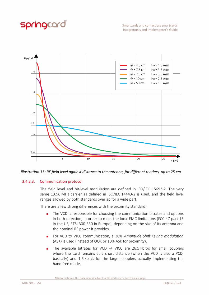
Smartcards and contactless smartcardsIntegrators's and Implementer's Guide
Illustration 15: RF field level against distance to the antenna, for different readers, up to 25 cm
3.4.2.3. Communication protocol
The field level and bit-level modulation are defined in ISO/IEC 15693-2. The verysame 13.56 MHz carrier as defined in ISO/IEC 14443-2 is used, and the field levelranges allowed by both standards overlap for a wide part.
There are a few strong differences with the proximity standard:
The VCD is responsible for choosing the communication bitrates and optionsin both direction, in order to meet the local EMC limitations (FCC 47 part 15in the US, ETSI 300-330 in Europe), depending on the size of its antenna andthe nominal RF power it provides,
For VCD to VICC communication, a 30% Amplitude Shift Keying modulation(ASK) is used (instead of OOK or 10% ASK for proximity),
The available bitrates for VCD → VICC are 26.5 kbit/s for small couplerswhere the card remains at a short distance (when the VCD is also a PCD,basically) and 1.6 kbit/s for the larger couplers actually implementing thehand free mode,
All information in this document is subject to the disclaimers stated on last page.
PMD17041 - AA Page 53 / 128
Smartcards and contactless smartcardsIntegrators's and Implementer's Guide
The available bitrates for VICC → VCD are 26.5 kit/s (short distance) and6.6 kbit/s (hand free). The VCD may choose between two different load-modulation schemes, depending on its technology and expected signal/noiseratio of the surroundings.
3.4.2.4. Application-level protocol
The stack is topped by ISO/IEC 15693-3 that defines the VICC as a direct-accessmemory, divided into blocks, making it very close to a wired-logic proximity card.
This layer of the standard introduces the following concepts:
Every card is identified by a unique serial number, the UID. Every cardmanufacturer has its own Manufacturer ID, and is responsible of the unicityof the UIDs attributed under this Manufacturer ID (see 6.3.2),
The card is basically an unsecure storage. Securing the access – and maybethe communication – is possible only through proprietary commands (somecards may be password-protected, some other may feature a more advancedauthentication scheme based on cryptographic functions),
The memory is divided into blocks of fixed size – but every manufacturerchooses freely the size of its blocs (a lots of cards available on the markettoday have 4-B blocks, some others are 1-B or 2-B only, some 8-B or 16-B,and there’s no reason not to see larger blocks in the future),
The memory is read and written at block-level. Optional functions make itpossible to read/write more than one block at once (but never less),
The card may provide a lock mechanism to turn every block permanentlyread-only – given the lack of mandated security, this is the minimum featureto be sure that the data could not be modified after writing.
There is no provision in the standard to implement smartcard features (APDUs andfile-system) on top of the ISO/IEC 15693 stack, because running a cardmicrocontroller, even very small, on the weak RF field of a VCD located 1.5m away, isnot possible with today’s technology (or at least not possible at an acceptable cost).
But the technology evolves constantly, and so do the standards.
3.4.3. Vicinity contactless cards vs RFID HF tags or labels
The ISO smartcard workgroup is responsible for all the standards discussed untilthen. There are many other workgroups at ISO’s. One of them is in charge of RFID,radio-frequency identification.
The RFID workgroup is driven by key actors of logistics, warehouse and retails. Theyfocus on open-loop database-centric systems, in which the RFID chip is no more than
All information in this document is subject to the disclaimers stated on last page.
PMD17041 - AA Page 54 / 128
Smartcards and contactless smartcardsIntegrators's and Implementer's Guide
the pointer to a record in a database. Storing a large amount of data orimplementing complex cryptographic features in the chip is totally out of their scope.Basically, their first need is a (very) cheap technology, because they will use billionsof disposable tags. Also, a fast and reliable anticollision scheme is a must have, to beable to read dozens of tags at the same time.
The result of their work is the ISO/IEC 18000 family of standards; every radio-frequency band that could potentially be used for RFID applications is covered by itsown entry in the family. This includes for instance ISO/IEC 18000-2 for the LF ISMband (125/135 kHz) and ISO/IEC 18000-6 for the UHF ISM band (860/960 MHz).
Closer to our focus, ISO/IEC 18000-3 covers the HF ISM band, i.e. the 13.56 MHzfrequency. This standard is itself divided in three modes that are not interoperable24:
Mode 1 (ISO/IEC 18000-3M1) is very close to ISO/IEC 15693. A VICCcompliant with ISO/IEC 15693 may be used together with a ISO/IEC 18000-3M1 interrogator,
Mode 2 (ISO/IEC 18000-3M2) uses phase-jitter modulation (PJM) for thecoupler-to-tag channel, which is very different from the ASK or OOKmodulations used by the other HF standards,
Mode 3 (ISO/IEC 18000-3M3) is the ISO transcription of the GS1 EPC HF RFIDAir Interface. GS1 is the child organization born from EAN (Europe ArticleNumbering) and UCC (Uniform Code Council), the organizations behind thestandards for barcodes. The aim of GS1 is to replace barcodes by electronicproduct codes (EPC). The ISO/IEC 18000-3M3 protocol has been designed byGS1 to offer the best anticollision speed25.
SpringCard couplers that are ISO/IEC 15693 VCD could be used with ISO/IEC 18000-3 Mode 1 tags.
Mode 3 tags will be supported by future products (UID reading only).
There is no plan to support Mode 2 tags.
24 This means that a given system shall implement only 1 of the 3 modes, and that a system running another mode will cause significant interferences.
25 A high-end dedicated RFID reader is likely to identify up to 700 tags per second using ISO/IEC 18000-3M3, against up to 60 tags per second using ISO/IEC 18000-3M1.
All information in this document is subject to the disclaimers stated on last page.
PMD17041 - AA Page 55 / 128
Smartcards and contactless smartcardsIntegrators's and Implementer's Guide
3.5. NFC TagsNFC Forum Tags are not a new technology, but a way of using contactless cards toexchange in open-loop, mass-market applications.
3.5.1. NFC and the NFC Forum
In 2003, Philips (the provider of the MIFARE cards, NXP being in the past the PhilipsSemiconductors division) and Sony (the provider of the FeliCa cards) introduced anew concept of short range wireless network, using inductive coupling (i.e. near fieldtechnology) in the 13.56 MHz ISM band.
This concept was entitled near field communication – interface and protocol – 1(NFCIP-1). It has been adopted in 2005 as international standard ISO/IEC 18092.
This standard completes the classical active coupler/passive card scenario byintroducing active/active communication: both the coupler (or initiator) and the card(or target) may now generate the 13.56 MHz carrier alternatively. It also introduces apeer-to-peer communication mode, superseding the earlier command/response (ormaster/slave) schemes.
The peer-to-peer mode is theoretically ready to convey any kind of higher-levelnetwork and application protocols, hence the analogy between NFCIP-1 and TCP/IP.
Then, Philips and Sony partnered with Nokia (at that time the leader of the mobilephone market) to create NFC Forum. Their goal was to develop an ecosystem ofadded-value applications, combining all the technologies based on inductivecoupling in the 13.56MHz band: the new ISO/IEC 18092 peer-to-peerimplementation, and the pre-existing ISO/IEC 14443 and ISO/IEC 15693 coupler (orreader/writer) and card implementations.
Putting everything together, and after 10 years of existence, NFC Forum provides aconsistent set of specifications, largely adopted by mobile phone manufacturers andalso by mobile network operators, to do the following:
Have a mobile phone emulate a contactless smartcard – and be able to useits SIM card (or UICC) as a secure execution environment; this has led toApple Pay, Google Wallet and a few alternative contactless payment systems,and to the virtualization of public transport tickets into the phone,
All information in this document is subject to the disclaimers stated on last page.
PMD17041 - AA Page 56 / 128
Smartcards and contactless smartcardsIntegrators's and Implementer's Guide
Have two mobiles phones communicate together using NFCIP-1 “peer-to-peer” to exchange small pieces of information: a business card or a contactentry, a link to the running application or to the currently active web page,etc. This system is known as Windows Proximity Networking in Microsoft’sworld, and Android Beam in Android’s world26.
Have a mobile phone fetch small pieces of information from a static object: aNFC Tag.
The later is the concept that is detailed in the next paragraphs.
Developing in the mobile phone is out-of-the scope of this guide since it has little incommon with PC/SC and is strongly tied to the mobile system’s API. But at least, theconcepts at work when exchanging an APDU with a smartcard are the same.
Implementing card emulation or peer-to-peer using SpringCard couplers will beaddressed in a future guide.
3.5.2. The concept behind NFC Tags
Basically, NFC Tags are contactless cards holding some publicly-readable data. Thesedata are organized according to an open format. They should be understood andhandled the same way by all the “readers”. In most situations, the “reader” is asoftware component provided by the terminal’s operating system itself, namelyAndroid or iOS for smartphones.
Most frequent usages of NFC Tags are opening a web page in the smartphone’sbrowser, but there are many other innovative use cases as well: initiate a phone call,add a business card to the list of contacts (vCard), configure a wirelesscommunication channel (WiFi or Bluetooth automated pairing), launch andapplication and/or execute a custom action on the phone.
In short, NFC Tags provides the same functionality to end-users as 2D barcodes(QRCode / flashcode), but with a faster – and more user-friendly – gesture.
3.5.3. NFC Forum Data Exchange Format and Record Types
The public content that is stored in the card’s memory is organized according to a setof specifications edited by the NFC Forum.
26 NFC communication requires that the two phones stays in close proximity, which is a terrible user experience when the duration of the exchange increases. For this reason, NFC peer-to-peer is limited to 1 or a few KB of data only. When more data are to be transmitted, both peers negotiate the opening of a new communication channel, based on Bluetooth or WiFi. The NFC channel is then used only for handshaking, the devices do a handover and communicate through the faster, longer-distance 2.4 GHz wireless channel.
All information in this document is subject to the disclaimers stated on last page.
PMD17041 - AA Page 57 / 128
Smartcards and contactless smartcardsIntegrators's and Implementer's Guide
The top level specification is called a NFC Forum Data Exchange Format (NDEF). ANDEF message contains one or a few records. The specification of the records arenamed Record Type Definitions (RTD).
The commonly used RTDs are
URI or URL (http:, https:, mailto:, callto:, smsto: …),
Text, to store an informative text that could be displayed to the user,
Arbitrary MIME data (for instance to store a small icon using the image/pngtype, or a business card with the text/x-vCard type),
Connection handover (WiFi or Bluetooth automated pairing),
Signature, holding the proof that the NFC Tag has been created by a certainissuer, and that the NDEF message has not been altered.
The smartposter RTD refers to a compound record, holding an URL, a Text and anaction verb (open, save, print..).
3.5.4. List of compliant PICCs / VICCs
NFC Forum content could be stored on any card that has enough memory to storethe NDEF message itself and the associated headers27.
Following the urge for a total interoperability between any NFC Tag and any NFC-enabled smartphone, the NFC Forum has limited its list of ‘officially compliant’ cardsproviders to only 5 families of contactless chips28.
3.5.4.1. Type 1 Tag (T1T)
The NFC Forum T1T specification is a copy/paste of the datasheet of the “Topaz”card, a low-cost, wired-logic PICC using a custom protocol based on ISO/IEC 14443-2type A bit-level modulation. The card has been developed by Innovision Research &Technology, now a part of Broadcom.
As any other wired-logic card, Type 1 Tags are supported by PC/SC couplers thanks tothe embedded APDU-Processor, through the READ BINARY and UPDATE BINARYinstructions. Once stored in the Tag, the NDEF message may be write-protected bysetting a lock byte.
27 They could also be pushed through a peer-to-peer communication channel (NFC beam)28 Until 2016, only types 1 to 4 were defined, therefore a lots of implementation may still lack support for type 5
All information in this document is subject to the disclaimers stated on last page.
PMD17041 - AA Page 58 / 128
Smartcards and contactless smartcardsIntegrators's and Implementer's Guide
3.5.4.2. Type 2 Tag (T2T)
The NFC Forum T2T specification is a copy/paste of the datasheet of the “MIFAREUltraLight” card by NXP (formerly Philips Semiconductors, Philips being one of thefounders of the NFC Forum)29. This card is also a low-cost, wired-logic PICC, that hasbeen designed with disposable transport tickets in mind. It uses a custom protocolon top of ISO/IEC 14443 up to -3, type A.
The “up to -3” makes it faster and more interoperable with old generations ofcouplers than the T1T.
The initial MIFARE UltraLight card was limited to 48 bytes of storage, but NXP nowoffers under the NTAG brand capacities going up to 2KB. Infineon also has aninteresting portfolio of chips and cards compliant with T2T (my-d NFC).
The PC/SC embedded APDU-Processor gives access to Type 2 Tags through the sameREAD BINARY and UPDATE BINARY instructions. Also special lock bytes make itpossible to turn the Tag read-only.
3.5.4.3. Type 3 Tag
The NFC Forum T3T specification is a copy/paste of the datasheet of the “FeliCa Lite”card by Sony. This is a light-weight version of Sony’s original FeliCa card, with thesecurity features removed. It uses a Japanese protocol (JIS X 6319-4) named “NFC-F”in NFC Forum’s documentations).
The PC/SC embedded APDU-Processor gives access to Type 3 Tags through the sameREAD BINARY and UPDATE BINARY instructions.
3.5.4.4. Type 4 Tag
The NFC Forum T4T specification defines how to use a generic, interoperable,contactless smartcard to store a NDEF message.
The card shall support both ISO/IEC 14443 up to -4 (either type A or B, respectivelynamed “NFC-A” and “NFC-B” in NFC Forum’s documentations). On top of that, thecard shall support the ISO/IEC 7816-4 command set (SELECT APPLICATION, SELECTFILE, READ BINARY) and provide 2 files to store a header and the NDEF messageitself.
The specification does not describe how the files are created, nor how to write theircontents, since NFC Forum focuses on the use (reading) and not on the issuingprocess.
Virtually any contactless smartcard may therefore be used to implement a T4T.Notably, SpringCard’s SDK has an example on how to format a NXP Desfire EV1 tobecome a valid T4T.
STMicroElectronics also has a portfolio of smartcards already formatted as T4T.
29 For more information regarding the MIFARE family, read 3.6.1.
All information in this document is subject to the disclaimers stated on last page.
PMD17041 - AA Page 59 / 128
Smartcards and contactless smartcardsIntegrators's and Implementer's Guide
The NDEF may be locked, or its write access may be controlled by a password or anykind of authentication method, depending on the features the card supports – andon the features the developer has decided to use.
3.5.4.5. Type 5 Tag
Adopted in 2016, the NFC Forum T5T specification defines how to use an ISO/IEC15693 VICC to store a NDEF message (“NFC-V” technology in NFC Forum’sdocumentations).
There is not much to add here: PC/SC couplers have been supporting for VICCs forlong. The memory is accessed through READ BINARY and UPDATE BINARYinstructions translated by the embedded APDU Processor to the Read Block / WriteBlock commands defined in ISO/IEC 15693-3.
Compliant cards could be found at NXP’s (ICODE-SLI family), STMicroElectronics’ (LRfamily), Infineon’s (my-d Vicinity family) and Texas Intrument (Tag-IT family).
All information in this document is subject to the disclaimers stated on last page.
PMD17041 - AA Page 60 / 128
Smartcards and contactless smartcardsIntegrators's and Implementer's Guide
3.6. Key actors and brands
3.6.1. NXP, ex Philips Semiconductors
3.6.1.1. MIFARE – The historical background
In the early 1990’s, an Austrian company called Mikron introduced an emergingtechnology: a wired-logic card featuring semi-structured storage and some kind ofsecurity, using inductive coupling at 13.56 MHz to communicate with its coupler.
As the 1st expected marked was the automatic fare collection, the card was namedMIFARE for MIkron FARE collection. In 1994, Mikron started working with the ISOsmartcard committee on the development of what would become ISO/IEC 14443(type A).
In 1995, Philips purchased Mikron and the MIFARE technology. Later on, Philipsdecided to split its assets and Philips Semiconductors became NXP.
Philips / NXP decided to use the brand as a common name for an ever growing familyof PICCs. Most of these products are still wired-logic cards (MIFARE Classic, MIFAREUltraLight), but some others are microprocessor-based cards (MIFARE Pro, ProX,SmartMX, MIFARE DESFire, MIFARE Plus).
3.6.1.2. MIFARE Classic
Illustration 16: Outprint of a MIFARE Classic promotional card
All information in this document is subject to the disclaimers stated on last page.
PMD17041 - AA Page 61 / 128
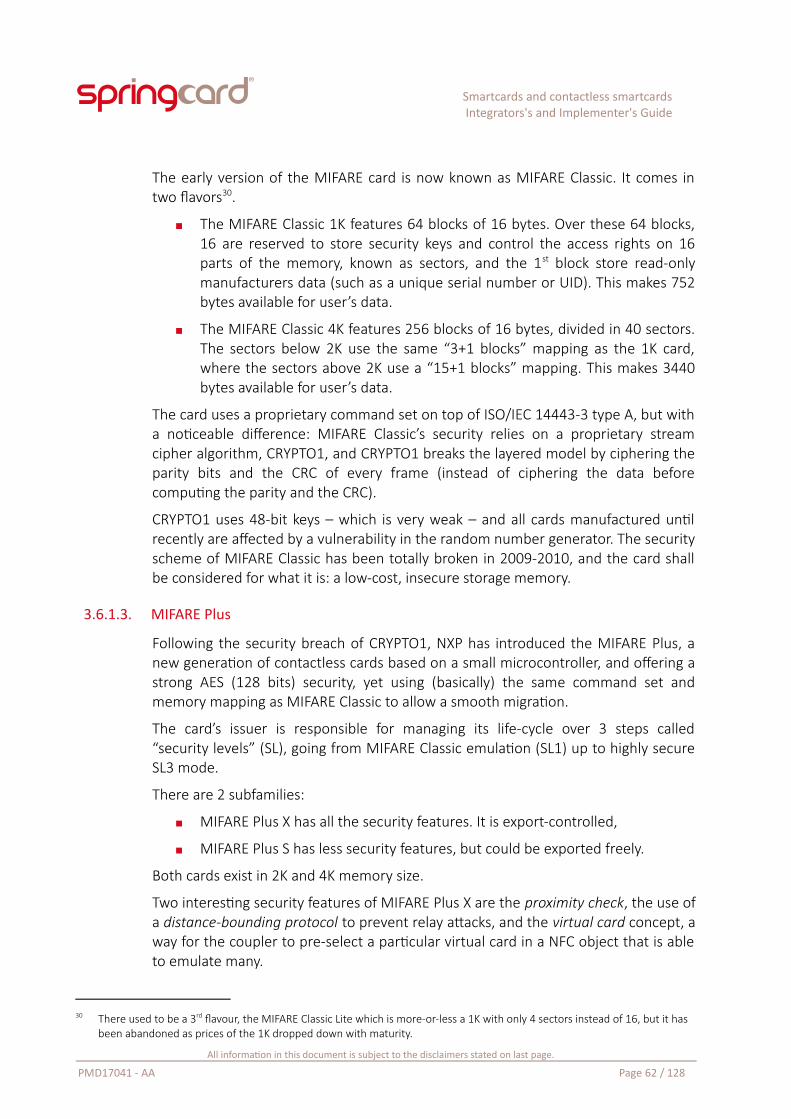
Smartcards and contactless smartcardsIntegrators's and Implementer's Guide
The early version of the MIFARE card is now known as MIFARE Classic. It comes intwo flavors30.
The MIFARE Classic 1K features 64 blocks of 16 bytes. Over these 64 blocks,16 are reserved to store security keys and control the access rights on 16parts of the memory, known as sectors, and the 1st block store read-onlymanufacturers data (such as a unique serial number or UID). This makes 752bytes available for user’s data.
The MIFARE Classic 4K features 256 blocks of 16 bytes, divided in 40 sectors.The sectors below 2K use the same “3+1 blocks” mapping as the 1K card,where the sectors above 2K use a “15+1 blocks” mapping. This makes 3440bytes available for user’s data.
The card uses a proprietary command set on top of ISO/IEC 14443-3 type A, but witha noticeable difference: MIFARE Classic’s security relies on a proprietary streamcipher algorithm, CRYPTO1, and CRYPTO1 breaks the layered model by ciphering theparity bits and the CRC of every frame (instead of ciphering the data beforecomputing the parity and the CRC).
CRYPTO1 uses 48-bit keys – which is very weak – and all cards manufactured untilrecently are affected by a vulnerability in the random number generator. The securityscheme of MIFARE Classic has been totally broken in 2009-2010, and the card shallbe considered for what it is: a low-cost, insecure storage memory.
3.6.1.3. MIFARE Plus
Following the security breach of CRYPTO1, NXP has introduced the MIFARE Plus, anew generation of contactless cards based on a small microcontroller, and offering astrong AES (128 bits) security, yet using (basically) the same command set andmemory mapping as MIFARE Classic to allow a smooth migration.
The card’s issuer is responsible for managing its life-cycle over 3 steps called“security levels” (SL), going from MIFARE Classic emulation (SL1) up to highly secureSL3 mode.
There are 2 subfamilies:
MIFARE Plus X has all the security features. It is export-controlled,
MIFARE Plus S has less security features, but could be exported freely.
Both cards exist in 2K and 4K memory size.
Two interesting security features of MIFARE Plus X are the proximity check, the use ofa distance-bounding protocol to prevent relay attacks, and the virtual card concept, away for the coupler to pre-select a particular virtual card in a NFC object that is ableto emulate many.
30 There used to be a 3rd flavour, the MIFARE Classic Lite which is more-or-less a 1K with only 4 sectors instead of 16, but it has been abandoned as prices of the 1K dropped down with maturity.
All information in this document is subject to the disclaimers stated on last page.
PMD17041 - AA Page 62 / 128
Smartcards and contactless smartcardsIntegrators's and Implementer's Guide
Also the virtual card concept increases the level of privacy of the contactless system,because the card may use a random protocol-level identifier (RID) instead of sendingits a unique identifier (UID) in response to the coupler’s polling loop.
Only a coupler belonging to the same “owner” as the card – and therefore sharing asecret key with the card – will then be able to retrieve the actual UID and startprocessing the card.
3.6.1.4. MIFARE UltraLight and NTAG
The low-end of the family is the MIFARE UltraLight, a chip with only 48 bytesavailable for user’s data, and no security. It targets low-cost applications, where thecard could be disposed-of after a single or a few uses only.
Being a cheap yet fast wired-logic card, the MIFARE UltraLight is the foundation ofthe NFC Forum Tag 2 standard (see paragraph 3.5.4.2). Chips fully compliant withMIFARE UltraLight, but with a larger memory capacity, are now sold by NXP underthe NTAG brand.
Another derivate of the MIFARE UltraLight is the MIFARE UltraLight C that includesan authentication scheme based on the 3DES algorithm (112 bits). This card targetsthe market of disposable tickets, typically in the public transport field.
3.6.1.5. SmartMX
SmartMX is NXP’s current family in secure microcontrollers, based on an 8051 (8-bit)architecture. It is marketed to host eGov applications (passports, ID card, healthcard…) or to power NFC-aware objects in the IoT world, and supersedes the earlierMIFARE Pro and MIFARE ProX families.
NXP also maintains JCOP, a JavaCard operating system initially developed togetherwith IBM. JCOP allows card-application developers to develop Java “cardlets” for theSmartMX chip.
All information in this document is subject to the disclaimers stated on last page.
PMD17041 - AA Page 63 / 128
Smartcards and contactless smartcardsIntegrators's and Implementer's Guide
3.6.1.6. DESFire
The DESFire contactless smartcard is based on a core similar to the SmartMX, but isnot open to card-applications developers. The chip comes with a general purposeoperating system in ROM, that offers a simple directory structure and files.
The card communicates using ISO/IEC 14443-4 type A. The command set isproprietary, but could be encapsulated to comply with the APDU format of ISO/IEC7816-4. A few ISO/IEC 7816-4 instructions have been introduced in version EV1 toease the adoption of the DESFire card in open, interoperable architectures.
Last version is EV2, that adds the proximity check concept (introduced on MIFAREPlus) and more notably a delegated administration model, that solves most of theissues of multi-application card schemes.
Regarding the security aspects, the 1st generation rely on 3DES with 2 keys (112 bits)for mutual authentication and ciphering. EV1 and EV2 also support AES (128 bits)and 3DES with 3 keys (168 bits).
All information in this document is subject to the disclaimers stated on last page.
PMD17041 - AA Page 64 / 128
Smartcards and contactless smartcardsIntegrators's and Implementer's Guide
3.6.1.7. ICODE
ICODE is NXP’s brand name for vicinity and RFID products. The pre-standard ICODE-1has been discontinued for long, and three families exist today:
ICODE-SLIX and ICODE SLIX 2 are ISO/IEC 15693 VICCs, also compliant withISO/IEC 18000-3M1,
ICODE DNA are also ISO/IEC 15693 VICCs, but they introduce high-endsecurity (AES-based dynamic mutual authentication) that was previouslyavailable only on PICCs,
ICODE ILT are compliant with ISO/IEC 18000-3M3 and EPC HF.
3.6.2. STMicroElectronics
3.6.2.1. Wired-logic PICCs
STMicroElectronics SR chips offer a short-range RFID interface compatible withISO/IEC 14443-2 (bit-level modulation) type B, and the frame format of ISO/IEC14443-3 type B. The anticollision scheme as well as the top-level command set areproprietary.
The 1st generation (SR176) and its descendants (SRT512, SRI512, SRI2K, SRI4K) areused as single-trip ticket in the public transport field, mostly embedded in disposablepaper cards.
The SR series is now superseded by the ST25TB family (ST25TB512, ST25B02K,ST25B04K). Chips in this family are compatible with the previous generation from thecoupler point of view.
The ST25TA family are contactless smartcards (ISO/IEC 14443, type A) alreadyformatted to be an NFC Forum Type 4 Tag.
3.6.2.2. MCUs for PICCs
STMicroelectronics offers secure microcontrollers (ST21, ST33), based on ARM cores,to smartcard developers. They are for instance the platform powering a lot ofCalypso cards.
All information in this document is subject to the disclaimers stated on last page.
PMD17041 - AA Page 65 / 128
Smartcards and contactless smartcardsIntegrators's and Implementer's Guide
3.6.2.3. VICCs
The LR series, as the initials suggest, is ST’s long-range RFID family. They are fullycompliant with ISO/IEC 15693.
The LR series will be shortly superseded by the new ST25TV family.
3.6.3. Infineon
3.6.3.1. Wired-logic PICCs
Infineon SRF 66R “my-d proximity” are ISO/IEC 14443-3 type A PICCs. They use thesame command set as NFC Type 2 Tags, plus a proprietary authentication scheme.
The family includes products branded “my-d NFC” with no authentication and thememory initialized as a NDEF container.
Infineon is also a MIFARE licensee and offers a clone of the Classic 1K (SLE 66R35).
3.6.3.2. MCUs for PICCs
Infineon has a wide range of secure microcontrollers (16-bit core) with ISO/IEC14443 interface (SLC32, SLE77, SLE78). They are the basis of many payment ortransport cards. Some of them may incorporate a MIFARE Classic emulation.
3.6.3.3. VICCs
Infineon SRF 55V “my-d vicinity” are ISO/IEC 15693 + ISO/IEC 18000-3M1 VICCs.Some chips in the family include a proprietary authentication scheme.
3.6.4. Texas Instrument
3.6.4.1. VICCs
The Tag-it HF-I chips are fully compliant with ISO/IEC 15693. They can be used as NFCType 5 Tags as well. Texas Instrument offers a very wide choice of ready-to-use inlaysbased on these chips.
All information in this document is subject to the disclaimers stated on last page.
PMD17041 - AA Page 66 / 128
Smartcards and contactless smartcardsIntegrators's and Implementer's Guide
3.6.5. Atmel (now Microchip)
3.6.5.1. Wired-logic PICCs
Atmel CryptoRF (AT88SCxxxxCRF) are wired-logic contactless chips or ready-to-usetags, using ISO/IEC 14443-2 (bit-level modulation) and ISO/IEC 14443-3 (frames andanticollision) type B.
All information in this document is subject to the disclaimers stated on last page.
PMD17041 - AA Page 67 / 128
Smartcards and contactless smartcardsIntegrators's and Implementer's Guide
4. PC/SC Stack – role, specificities, alternatives
4.1. IntroductionPC/SC stands for “Personal Computer / Smart Card”. It’s the de facto standard to usesmartcards – and smartcard couplers – from a mainstream computer environment.
PC/SC has been written and is maintained since 1996 by the PC/SC Workgroup.
The PC/SC Workgroup’s website is: www.pcscworkgroup.com
PC/SC provides a complete abstraction of the underlying coupler and driver. AllSpringCard PC/SC couplers comply with this standard. It ensures interoperabilityamong manufacturers: a SpringCard coupler may be used with a PC/SC-awareapplication written with another coupler in mind, and vice-versa.
Interestingly, PC/SC makes no difference between a contact coupler (CD) and acontactless coupler (PCD/VCD), and hides most of the specificities of eithertechnologies. Last but not least, PC/SC makes it possible to operate wire-logic cards(and more specifically wired-logic contactless cards, RFID labels and NFC tags in thecase of SpringCard contactless couplers) using “classical” APDUs, as if they weremicrocontroller-based smartcards.
The possible alternatives to PC/SC are covered by chapter 8.
4.2. The PC/SC architecture (and vocabulary)PC/SC relies on a layered architecture, going from the coupler (smartcard reader)and its driver up to the high-level application programming interface (API) through amiddleware (system-provided processes and libraries) that implements both thedevice abstraction facility and a strong isolation between the client card-awareapplications – for security reasons31.
Illustration 17 (page 70) shows the PC/SC stack.
4.2.1. Smartcards, readers and drivers
The smartcard or ICC (Integrated Circuit Card) is inserted into a reader or IFD(InterFace Device). This is, strictly-speaking, a “coupler” and not a reader.
The IFD, a hardware product, is associated to a reader driver or IFD handler.
31 Imagine you enter your PIN in an application to unlock your credit card, or your phone’s SIM card, to explore its content. Do you really want that another application (maybe a malware) could also communicate with your now unlocked card?
All information in this document is subject to the disclaimers stated on last page.
PMD17041 - AA Page 68 / 128
Smartcards and contactless smartcardsIntegrators's and Implementer's Guide
The manufacturer of the product has two options: either provide a custom driver for“all” the operating systems, or implements its product following an openspecification, in the hope that the operating systems will provide a generic driverbased on the same open specification. This is the option opened by the USBworkgroup with the USB contact card interface device (CCID) specification, and this isthe option chosen by SpringCard for its PC/SC couplers.
Thanks to this USB CCID profile, SpringCard USB PC/SC couplers are supported by ageneric, open source, USB CCID driver, that is available on Linux and many otherUnix-like systems. Apple also uses the source code of this driver to support the CCIDUSB PC/SC couplers in Mac OS X.
Microsoft Windows also provides a generic USB CCID driver in Windows, butunfortunately this driver as a lot of limitations. Therefore, SpringCard provides itsown USB CCID driver for Windows.
4.2.2. The middleware
The drivers are under the control of the PC/SC middleware or ICC resource manager.
This middleware is responsible for maintaining the list of currently connectedcouplers, notifying the applications when a smartcard is inserted in a coupler, andpreventing two (or more) applications from accessing the same card simultaneously.
On Windows, the PC/SC middleware is implemented by a system service named“Smart Card Service” (scardsvr.exe). On Linux/Unix-likes, it is implemented in thepcscd daemon.
4.2.3. The API
An application that aims to use smartcards – a ICC-aware application – loads a user-land dynamic library to invoke the services provided by the PC/SC middlewarethrough entry-points specified as the “PC/SC API”.
On Windows, the shared PC/SC library is winscard.dll, and libpcsclite.so onLinux/Unix-likes. There are various wrappers for managed platforms (such as .NET orJava) or script engines (Python, Perl, Lua, JS, etc).
4.2.4. Helpers
In-between the middleware and the application, the ‘helpers’ are optional softwarecomponents that give a more abstract view to the application developer.
For instance, a card providing general-purpose cryptographic primitives (ciphering,deciphering, digital signature) is likely to be associated with a ‘card helper’ thatexposes its primitives with a high-level, interoperable, object-oriented approach.
All information in this document is subject to the disclaimers stated on last page.
PMD17041 - AA Page 69 / 128
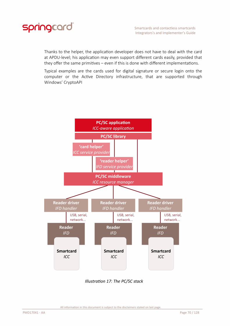
Smartcards and contactless smartcardsIntegrators's and Implementer's Guide
Thanks to the helper, the application developer does not have to deal with the cardat APDU-level; his application may even support different cards easily, provided thatthey offer the same primitives – even if this is done with different implementations.
Typical examples are the cards used for digital signature or secure login onto thecomputer or the Active Directory infrastructure, that are supported throughWindows’ CryptoAPI
Illustration 17: The PC/SC stack
All information in this document is subject to the disclaimers stated on last page.
PMD17041 - AA Page 70 / 128
PC/SC applicationICC-aware application
Reader driverIFD handler
ReaderIFD
USB, serial,network...
SmartcardICC
PC/SC middlewareICC resource manager
Reader driverIFD handler
ReaderIFD
USB, serial,network...
SmartcardICC
Reader driverIFD handler
ReaderIFD
USB, serial,network...
SmartcardICC
PC/SC library
‘card helper’ICC service provider
‘reader helper’IFD service provider
Smartcards and contactless smartcardsIntegrators's and Implementer's Guide
4.3. PC/SC on Microsoft WindowsMicrosoft was one of the founders of the PC/SC workgroup, and all desktop systemssince Windows 95 and Windows NT 4.0 do include the middleware. This is not soclear for mobile or embedded systems (Windows CE, Windows Phone, Windows IoTCore) where the middleware may be installed or not, depending on how the systemimage is generated.
Following the deep integration of NFC technologies into the operating system of atoday’s mobile phone, Microsoft has introduced in its Windows Phones and SurfaceTablet a new Proximity API, that is an alternative to PC/SC to communicate withcontactless cards.
But to-date, the Proximity API is strictly tied to a few specific hardware, where theNFC interface is directly connected to the core CPU, and not a remote (USB /network / other?) device.
Also, the Proximity API is limited to NFC Forum’s specifications, and therefore offerslittle to no support for the many families of wired-logic contactless cards that havenot been endorsed by the NFC Forum.
Hence, PC/SC remains the interface of choice for pluggable contactless couplers.
4.3.1. Official documentation
The documentation related to PC/SC is sprinkled among many pages of Microsoft’swebsites. We list here only the two main entry points:
A general introduction to using the smartcard under Windows, simply entitled“Smart Card” is available at:
https://msdn.microsoft.com/en-us/library/bb742533.aspx
The article “Accessing a Smart Card” is the entry-point to explore the API, as it isimplemented by Microsoft, by clicking “SCardConnect” after having read theintroductory text:
https://msdn.microsoft.com/en-us/library/windows/desktop/aa374709(v=vs.85).aspx
All information in this document is subject to the disclaimers stated on last page.
PMD17041 - AA Page 71 / 128
Smartcards and contactless smartcardsIntegrators's and Implementer's Guide
4.3.2. Technical implementation
The PC/SC API is exposed through a single dynamically callable library, winscard.dll .
Key functions of the PC/SC API are introduced in chapter 5, and more completelydocumented in doc. PMDZ061.
C and C++ developers building native Windows applications use the winscard.hheader and link their program against winscard.lib, which provide the static entrypoints to use winscard.dll . Care must be taken that for every function that takes astring as parameter (for instance, the name of the coupler in SCardConnect), thelibrary exposes both ASCII and UNICODE versions (SCardConnectA andScardConnectW).
Managed applications must use a wrapper to access the PC/SC stack throughwinscard.dll ; a Java application is likely to use the standard wrapper namedjavax.smartcardio.
For .NET applications, there is no standard wrapper. SpringCard proposes its ownwrapper for convenience (look for the SpringCard.PCSC namespace in the SDK).There are also plenty of open-source alternatives, and also a few paid solutions(including ActiveX components for legacy development environments).
4.3.3. Writing and using card helpers
Microsoft recommends to write a “card helper”, or ICC service provider, a reusablesoftware component that provides high-level access to the services offered by thesmartcard. This simplifies the job of the top-level application developer, who doesnot have to manipulate the APDUs and any raw data in his business logic.
Vendors of cryptographic smartcards, used for digital signature and/or to logon thesystem, typically do so by providing either a Smart Card Cryptographic Provider (CSP)or a Smart Card Mini Driver.
Smart Card Cryptographic Service Provider specification:https://msdn.microsoft.com/en-us/library/ms953432.aspx
Smart Card Mini Driver specification:https://msdn.microsoft.com/en-us/windows/hardware/drivers/smartcard/smartcard-minidrivers
Anyway, in most projects, it is much simpler – and perfectly fine for thedeveloper(s) – to implement the communication with the smartcard directly into theapplication. It is also possible to implement a basic helper through a DLL or a ClassLibrary, without bothering with CSP or Mini Driver specifications.
All information in this document is subject to the disclaimers stated on last page.
PMD17041 - AA Page 72 / 128
Smartcards and contactless smartcardsIntegrators's and Implementer's Guide
Doc. TBD introduces such a Class Library: SpringCard.NfcForum.Tags; written inC#, it allows an application developer to read or write NFC Forum Tags at a highabstraction level, on top of the SpringCard.PCSC classes.
4.3.4. Limitations
Some parts of Windows’ PC/SC stack have always been the source of issues whenmore than 10 couplers are connected to the computer.
Starting with Windows 8, Microsoft officially limits the use of its PC/SC stack to tencouplers.
You may attach more than ten coupling devices to the computer, butSCardListReaders, the command that enumerates the couplers, will never returnmore than ten. The other couplers are ignored.
Please read Microsoft KB #3144446 for reference and explanations.
Some SpringCard PC/SC couplers, like the CSB HSP or the CrazyWriter HSP, could hostin a single USB device as many as 5 or 6 PC/SC couplers (1 contactless slot, 1 ID-1slot, 3 or 4 SIM/SAM slots). It is very easy to overflow the system’s limitations withthese products.
4.4. Linux and other UNIX-like systemsA group of volunteers has created MUSCLE, Movement for the Use of Smart Cards ina Linux Environment. They have developed, and now maintain, PCSC-Lite, the open-source PC/SC stack for Linux and other UNIX-like systems.
MUSCLE PCSC-Lite project: http://www.musclecard.com
Direct link to PC/SC stack: http://pcsclite.alioth.debian.org
The PC/SC middleware is implemented in a daemon named pcscd. The PC/SC API isexposed through a single dynamically callable library, libpcsclite.so.1 . Thecorresponding header file is named winscard.h for compatibility with Windowsapplications at source code level.
SpringCard USB PC/SC couplers are supported thanks to the open-source CCID driverdeveloped for PCSC-Lite by Ludovic Rousseau, as documented here:
Direct link to PCSC-Lite’s USB CCID driver:https://pcsclite.alioth.debian.org/pcsclite.html
All information in this document is subject to the disclaimers stated on last page.
PMD17041 - AA Page 73 / 128
Smartcards and contactless smartcardsIntegrators's and Implementer's Guide
For SpringCard non-USB couplers (for instance, TwistyWriter-IP PC/SC relies on aCCID over TCP over Ethernet implementation), SpringCard provides an open-sourcedriver32.
SpringCard NetPCSC driver for PCSC-Lite: http://tech.springcard.com/2016/springcard-netpcsc-for-pcsc-lite/
Ludovic Rousseau also authors a very interesting blog related to smartcarddevelopment in the UNIX-world. It also documents how to access the PC/SC API fromvarious scripting languages (Lua, Python, PERL, Node.js, etc).
Ludovic Rousseau’s blog: https://ludovicrousseau.blogspot.fr/
SpringCard is not connected with and does not sponsor or endorse 3rd party open-source developers.
4.5. macOS XApple provides a fork of the PCSC-Lite stack (and of the open-source USB CCIDdriver) within their UNIX-like system. The dynamically callable library is renamedPCSC.framework/PCSC.
The documentation is hosted on GitHub:
Apple Smart Card Services: https://smartcardservices.github.io/
Once again, Ludovic Rousseau’s blog is a very interesting source of information, withmany tips (or bug explanations) related to Apple Mac OS X:
The ‘”Apple” keyword at Ludovic Rousseau’s:https://ludovicrousseau.blogspot.fr/search?q=apple
SpringCard is not connected with and does not sponsor or endorse 3rd party open-source developers.
32 SpringCard drivers for PCSC-Lite are forks of the original USB CCID driver for PCSC-Lite, and are released under the same LGPL license.
All information in this document is subject to the disclaimers stated on last page.
PMD17041 - AA Page 74 / 128
Smartcards and contactless smartcardsIntegrators's and Implementer's Guide
4.6. AndroidAs a Linux-based system, it would be logical that Android includes its version ofPCSC-Lite. But this is not the case in out-of-the-box system images.
Giesecke & Devrient, a german manufacturer of smartcards, promotes a complexproject named SEEK for Android, SEEK being “Secure Element Evaluation Kit”, thatincludes some efforts to port PCSC-Lite on Android.
Unfortunately, their promising pcscdroid project is not maintained anymore, and isstrictly limited to custom system images or to ‘rooted’ devices, which prevent anyadoption as a mainstream solution.
SEEK for Android main page: http://seek-for-android.github.io/
The Pcscdroid project:https://github.com/seek-for-android/pool/wiki/%5BUNMAINTAINED%5D-Pcscdroid
SpringCard is not connected with and does not sponsor or endorse 3rd party open-source developers.
All information in this document is subject to the disclaimers stated on last page.
PMD17041 - AA Page 75 / 128
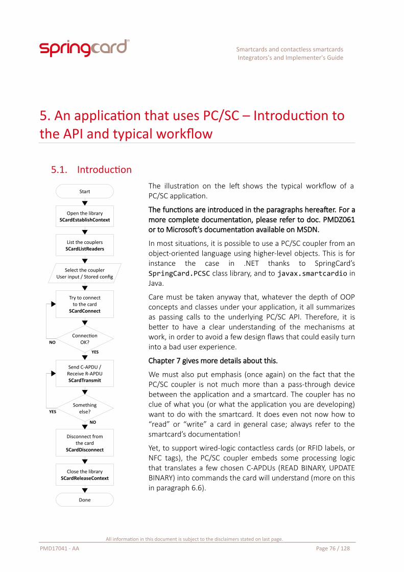
Smartcards and contactless smartcardsIntegrators's and Implementer's Guide
5. An application that uses PC/SC – Introduction to the API and typical workflow
5.1. IntroductionThe illustration on the left shows the typical workflow of aPC/SC application.
The functions are introduced in the paragraphs hereafter. For amore complete documentation, please refer to doc. PMDZ061or to Microsoft’s documentation available on MSDN.
In most situations, it is possible to use a PC/SC coupler from anobject-oriented language using higher-level objects. This is forinstance the case in .NET thanks to SpringCard’sSpringCard.PCSC class library, and to javax.smartcardio inJava.
Care must be taken anyway that, whatever the depth of OOPconcepts and classes under your application, it all summarizesas passing calls to the underlying PC/SC API. Therefore, it isbetter to have a clear understanding of the mechanisms atwork, in order to avoid a few design flaws that could easily turninto a bad user experience.
Chapter 7 gives more details about this.
We must also put emphasis (once again) on the fact that thePC/SC coupler is not much more than a pass-through devicebetween the application and a smartcard. The coupler has noclue of what you (or what the application you are developing)want to do with the smartcard. It does even not now how to“read” or “write” a card in general case; always refer to thesmartcard’s documentation!
Yet, to support wired-logic contactless cards (or RFID labels, orNFC tags), the PC/SC coupler embeds some processing logicthat translates a few chosen C-APDUs (READ BINARY, UPDATEBINARY) into commands the card will understand (more on thisin paragraph 6.6).
All information in this document is subject to the disclaimers stated on last page.
PMD17041 - AA Page 76 / 128
Start
Open the librarySCardEstablishContext
List the couplersSCardListReaders
Select the couplerUser input / Stored config
Try to connectto the card
SCardConnect
ConnectionOK?
Somethingelse?
Send C-APDU /Receive R-APDUSCardTransmit
Close the librarySCardReleaseContext
Disconnect fromthe card
SCardDisconnect
Done
YES
YES
NO
NO
Smartcards and contactless smartcardsIntegrators's and Implementer's Guide
5.2. Establish a PC/SC contextThe first step is to initialize the client part of the PC/SC API by calling theSCardEstablishContext function.
Within winscard.dll (or its counterpart for PCSC-Lite) this has the effect of opening acommunication channel with the middleware and to instantiate the variables.
In a multi-threaded application, every thread (that calls functions from the PC/SCAPI) shall have its own context.
LONG SCardEstablishContext(IN DWORD dwScope, IN LPCVOID *pvReserved1, IN LPCVOID *pvReserved2, OUT LPSCARDCONTEXT phContext);
For those non-familiar with the Hungarian notation used by Microsoft, let’s translate:
dwScope is a double-word (4 bytes) input value. Set it to the constantSCARD_SCOPE_SYSTEM (value = 2).
In the context of a terminal server or remote desktop session, dwScope tells thePC/SC middleware whether the application wants to use the server’s resources, theterminal’s, or the local user’s.
In any other contexts, use SCARD_SCOPE_SYSTEM with no hesitation.
pvReserved1 and pvReserved2 are constant input pointers to anything(LPCVOID stands for long pointer to a const void). Set them to NULL.
phContext is a pointer to a SCARDCONTEXT (LPSCARDCONTEXT is equivalentto void *SCARDCONTEXT), that will hold the output data after a successfulcall.
SCARDCONTEXT is an opaque handle. With a non-C/C++ language, use a genericpointer (System.IntPtr on .NET). This makes phContext a pointer to a generic pointer(ref System.IntPtr on .NET).
SCardEstablishContext, as well as all other functions from the PC/SC API, returns aLONG (signed long integer). On success, its value is SCARD_S_SUCCESS (value = 0).
Refer to paragraph 7.4 for a few information regarding the error codes and theirunderstanding.
All information in this document is subject to the disclaimers stated on last page.
PMD17041 - AA Page 77 / 128
Smartcards and contactless smartcardsIntegrators's and Implementer's Guide
5.3. List the PC/SC couplersGet a list of the available PC/SC couplers using the SCardListReaders function.LONG SCardListReaders(IN SCARDCONTEXT hContext, IN LPCTSTR mszGroups, OUT LPTSTR mszReaders, IN OUT LPDWORD pcchReaders);
Let’s explain the Hungarian notation and the parameters again:
hContext is the pointer you got as output to SCardEstablishContext,
mszGroups is a constant input pointers to a string: long pointer to a const “T”string, the “T” meaning that the string could use either single-byte characters(char) or multibyte characters (wchar_t)33. Set this parameter to NULL.
mszReaders is the output string that will hold the list of couplers after asuccessful call. It shall have been allocated by the caller application,
pcchReaders is a pointer to the length of the mszReaders string (in number ofcharacters, not number of bytes). On input, the caller application sets thepointed value to the allocated length. On output, the library tells how manycharacters are used by the string.
Classical examples use SCardListReaders twice: upon first call mszReaders is set toNULL, so pcchReaders provides the number of characters that must be allocated.Then the caller application allocates a string of the given length, and callsSCardListReaders a second time with it.
On modern systems, and given the limitation to 10 couplers on Windows, justallocate a large string (say, at least 1024 characters) once for all.
On output, mszReaders holds the list of couplers, in the form of a multi-string string.Now, what is a multi-string string? It’s an array of characters (char or wchar_tdepending). As any other string, every string in the array is zero-terminated (‘\0’character). The end of the array is marked by a double zero (“\0\0”).
javax.smartcardio implements SCardListReaders through the CardTerminals class.
SpringCard.PCSC for .NET implements SCardListReaders through the SCardReaderList class.
33 Actually, the SCardListReaders function has no existence. It’s an alias to either SCardListReadersA (ASCII implementation, the strings being handled as char[]) or SCardListReadersW (UNICODE implementation, the strings being handled as wchar_t[]). A C/C++ source including winscard.h will use either implementation depending on whether _UNICODE is defined or not.
All information in this document is subject to the disclaimers stated on last page.
PMD17041 - AA Page 78 / 128
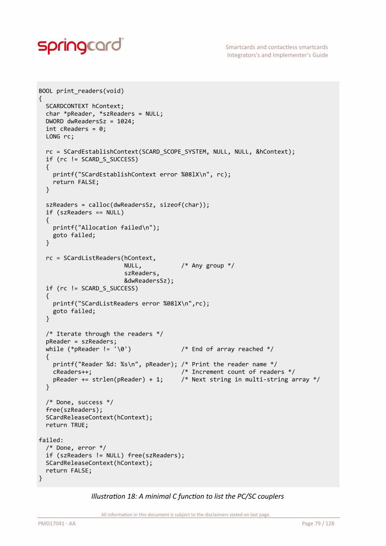
Smartcards and contactless smartcardsIntegrators's and Implementer's Guide
BOOL print_readers(void){ SCARDCONTEXT hContext; char *pReader, *szReaders = NULL; DWORD dwReadersSz = 1024; int cReaders = 0; LONG rc;
rc = SCardEstablishContext(SCARD_SCOPE_SYSTEM, NULL, NULL, &hContext); if (rc != SCARD_S_SUCCESS) { printf("SCardEstablishContext error %08lX\n", rc); return FALSE; }
szReaders = calloc(dwReadersSz, sizeof(char)); if (szReaders == NULL) { printf("Allocation failed\n"); goto failed; }
rc = SCardListReaders(hContext, NULL, /* Any group */ szReaders, &dwReadersSz); if (rc != SCARD_S_SUCCESS) { printf("SCardListReaders error %08lX\n",rc); goto failed; }
/* Iterate through the readers */ pReader = szReaders; while (*pReader != '\0') /* End of array reached */ { printf("Reader %d: %s\n", pReader); /* Print the reader name */ cReaders++; /* Increment count of readers */ pReader += strlen(pReader) + 1; /* Next string in multi-string array */ }
/* Done, success */ free(szReaders); SCardReleaseContext(hContext); return TRUE;
failed: /* Done, error */ if (szReaders != NULL) free(szReaders); SCardReleaseContext(hContext); return FALSE;}
Illustration 18: A minimal C function to list the PC/SC couplers
All information in this document is subject to the disclaimers stated on last page.
PMD17041 - AA Page 79 / 128
Smartcards and contactless smartcardsIntegrators's and Implementer's Guide
5.4. Is there a card in the coupler?Use the SCardGetStatusChange function to read the status of the coupler.LONG SCardGetStatusChange(IN SCARDCONTEXT hContext, IN DWORD dwTimeout, IN OUT LPSCARD_READERSTATE rgReaderState, IN DWORD cReaders);
Where:
hContext is the pointer you got as output to SCardEstablishContext,
dwTimeout is the time to wait for an event (in milliseconds). In this part ofthe document, we set it to 0 (return immediately),
SCardGetStatusChange could be used in two modes: non-blocking (query only), withthe dwTimeout parameter set to 0, or blocking until an event occurs is dwTimeout isnon-0. The later will be shown in 7.2 “Using background threads”.
In this chapter, we remain very basic: the user has a button to click to initiate thecard transaction, and we use SCardGetStatusChange to verify that there is actually acard in the coupler only when he clicks this button.
rgReaderState is an array of SCARD_READERSTATE structures – one entry percoupler you want to monitor, i.e. only one entry when you are working withone coupler only. On input, you write into the structure the name of thecoupler you are working with and its assumed current status (“don’t know” isa good assumption on first call!). On output, the structure contains the actualstatus of the coupler (no card, card present, card in use…). If there is a card inthe coupler, the structure also provides its ATR.
chReader is the number of entries in the rgReaderState array. With onecoupler only, we set it to 1.
Things will be clearer with an example: see illustration 19 on next page.
javax.smartcardio implements SCardGetStatusChange as CardTerminal.isCardPresent() (no wait) or CardTerminal.waitForCardAbsent(long timeout) (blocking).
SpringCard.PCSC implements SCardGetStatusChange as SCardReader.CardPresent.The algorithm “is there a card available in the coupler” that appears in illustration19 is implemented as SCardReader.CardAvailable.
All information in this document is subject to the disclaimers stated on last page.
PMD17041 - AA Page 80 / 128
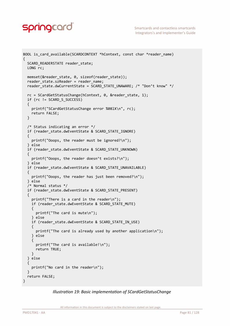
Smartcards and contactless smartcardsIntegrators's and Implementer's Guide
BOOL is_card_available(SCARDCONTEXT *hContext, const char *reader_name){ SCARD_READERSTATE reader_state; LONG rc;
memset(&reader_state, 0, sizeof(reader_state)); reader_state.szReader = reader_name; reader_state.dwCurrentState = SCARD_STATE_UNAWARE; /* "Don’t know" */
rc = SCardGetStatusChange(hContext, 0, &reader_state, 1); if (rc != SCARD_S_SUCCESS) { printf("SCardGetStatusChange error %08lX\n", rc); return FALSE; }
/* Status indicating an error */ if (reader_state.dwEventState & SCARD_STATE_IGNORE) { printf("Ooops, the reader must be ignored?\n"); } else if (reader_state.dwEventState & SCARD_STATE_UNKNOWN) { printf("Ooops, the reader doesn’t exists?\n"); } else if (reader_state.dwEventState & SCARD_STATE_UNAVAILABLE) { printf("Ooops, the reader has just been removed?\n"); } else /* Normal status */ if (reader_state.dwEventState & SCARD_STATE_PRESENT) { printf("There is a card in the reader\n"); if (reader_state.dwEventState & SCARD_STATE_MUTE) { printf("The card is mute\n"); } else if (reader_state.dwEventState & SCARD_STATE_IN_USE) { printf("The card is already used by another application\n"); } else { printf("The card is available!\n"); return TRUE; } } else { printf("No card in the reader\n"); } return FALSE;}
Illustration 19: Basic implementation of SCardGetStatusChange
All information in this document is subject to the disclaimers stated on last page.
PMD17041 - AA Page 81 / 128
Smartcards and contactless smartcardsIntegrators's and Implementer's Guide
5.5. Connect to the cardThe SCardConnect function opens a logical communication channel between theapplication and the card contained by a specific coupler.LONG SCardConnect(IN SCARDCONTEXT hContext, IN LPCTSTR szReader, IN DWORD dwShareMode, IN DWORD dwPreferredProtocols, OUT LPSCARDHANDLE phCard, OUT DWORD pdwActiveProtocol);
Where:
hContext is the pointer you got as output to SCardEstablishContext,
szReader is the name of the coupler,
dwShareMode shall be set to SCARD_SHARE_EXCLUSIVE for convenience,
dwPreferredProtocols shall be set to SCARD_PROTOCOL_T0|SCARD_PROTOCOL_T1 (logical OR) to let the coupler (or driver) decide whichprotocol is the best for card communication,
phCard is a pointer to a SCARDHANDLE, that will hold the logical channel’shandle after a successful call,
pdwActiveProtocol is a pointer to a DWORD that will tell which protocol hasbeen selected.
SCARDHANDLE is an opaque handle. With a non-C/C++ language, use a genericpointer (System.IntPtr on .NET). This makes phCard a pointer to a generic pointer(ref System.IntPtr on .NET).
In a multi-threaded application, it is a bad idea to share the hCard handle amongdifferent threads.
If the connection channel has been successfully opened, the function returnsSCARD_S_SUCCESS; *phCard is populated with the channel’s handle, andpdwActiveProtocol is populated with the transport protocol that has been selectedby the coupler (or driver). It is either
SCARD_PROTOCOL_T0 : for ISO/IEC 7816-3 T=0
SCARD_PROTOCOL_T1 : for ISO/IEC 7816-3 T=1, ISO/IEC 14443-4 (becausethe contactless block protocol “T=CL” is very close to T=1), and for all wired-logic contactless cards (because the coupler’s embedded APDU- Processorbehaves as a T=1 card).
If there is no card in the coupler, the function returns SCARD_E_NO_SMARTCARD. Ifthe card is already used by another application, it returns
All information in this document is subject to the disclaimers stated on last page.
PMD17041 - AA Page 82 / 128
Smartcards and contactless smartcardsIntegrators's and Implementer's Guide
SCARD_E_SHARING_VIOLATION. Of course other error codes are also possible in casea technical error occurs.
Refer to paragraph 7.4 for a few information regarding the other possible error codesand their understanding.
javax.smartcardio implements SCardConnect and the hCard as a Card object, returned by the CardTerminal.connect(String protocol) method, and the subsequent communication channel as a CardChannel channel..
SpringCard.PCSC implements the communication channel as a SCardChannel object, the implementation of SCardConnect being the SCardChannel.Connect() method.
All information in this document is subject to the disclaimers stated on last page.
PMD17041 - AA Page 83 / 128
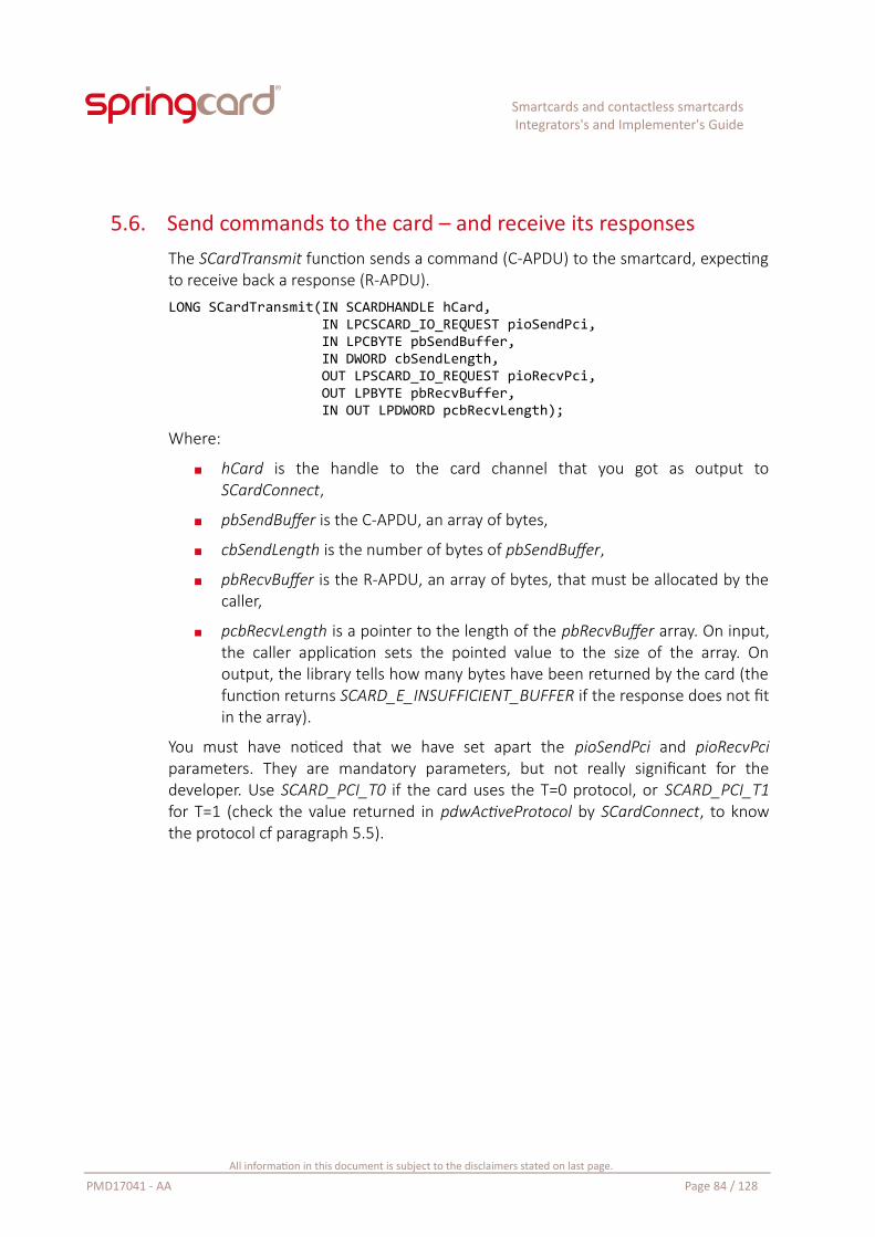
Smartcards and contactless smartcardsIntegrators's and Implementer's Guide
5.6. Send commands to the card – and receive its responsesThe SCardTransmit function sends a command (C-APDU) to the smartcard, expectingto receive back a response (R-APDU).LONG SCardTransmit(IN SCARDHANDLE hCard, IN LPCSCARD_IO_REQUEST pioSendPci, IN LPCBYTE pbSendBuffer, IN DWORD cbSendLength, OUT LPSCARD_IO_REQUEST pioRecvPci, OUT LPBYTE pbRecvBuffer, IN OUT LPDWORD pcbRecvLength);
Where:
hCard is the handle to the card channel that you got as output toSCardConnect,
pbSendBuffer is the C-APDU, an array of bytes,
cbSendLength is the number of bytes of pbSendBuffer,
pbRecvBuffer is the R-APDU, an array of bytes, that must be allocated by thecaller,
pcbRecvLength is a pointer to the length of the pbRecvBuffer array. On input,the caller application sets the pointed value to the size of the array. Onoutput, the library tells how many bytes have been returned by the card (thefunction returns SCARD_E_INSUFFICIENT_BUFFER if the response does not fitin the array).
You must have noticed that we have set apart the pioSendPci and pioRecvPciparameters. They are mandatory parameters, but not really significant for thedeveloper. Use SCARD_PCI_T0 if the card uses the T=0 protocol, or SCARD_PCI_T1for T=1 (check the value returned in pdwActiveProtocol by SCardConnect, to knowthe protocol cf paragraph 5.5).
All information in this document is subject to the disclaimers stated on last page.
PMD17041 - AA Page 84 / 128
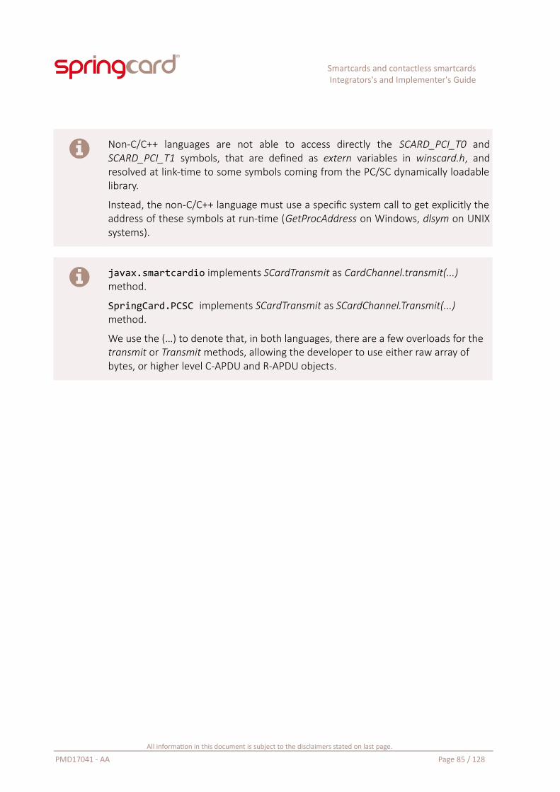
Smartcards and contactless smartcardsIntegrators's and Implementer's Guide
Non-C/C++ languages are not able to access directly the SCARD_PCI_T0 andSCARD_PCI_T1 symbols, that are defined as extern variables in winscard.h, andresolved at link-time to some symbols coming from the PC/SC dynamically loadablelibrary.
Instead, the non-C/C++ language must use a specific system call to get explicitly theaddress of these symbols at run-time (GetProcAddress on Windows, dlsym on UNIXsystems).
javax.smartcardio implements SCardTransmit as CardChannel.transmit(...) method.
SpringCard.PCSC implements SCardTransmit as SCardChannel.Transmit(...) method.
We use the (…) to denote that, in both languages, there are a few overloads for the transmit or Transmit methods, allowing the developer to use either raw array of bytes, or higher level C-APDU and R-APDU objects.
All information in this document is subject to the disclaimers stated on last page.
PMD17041 - AA Page 85 / 128
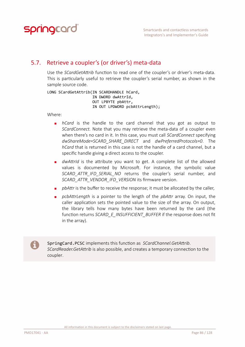
Smartcards and contactless smartcardsIntegrators's and Implementer's Guide
5.7. Retrieve a coupler’s (or driver’s) meta-dataUse the SCardGetAttrib function to read one of the coupler’s or driver’s meta-data.This is particularly useful to retrieve the coupler’s serial number, as shown in thesample source code.LONG SCardGetAttrib(IN SCARDHANDLE hCard, IN DWORD dwAttrId, OUT LPBYTE pbAttr, IN OUT LPDWORD pcbAttrLength);
Where:
hCard is the handle to the card channel that you got as output toSCardConnect. Note that you may retrieve the meta-data of a coupler evenwhen there’s no card in it. In this case, you must call SCardConnect specifyingdwShareMode=SCARD_SHARE_DIRECT and dwPreferredProtocols=0. ThehCard that is returned in this case is not the handle of a card channel, but aspecific handle giving a direct access to the coupler.
dwAttrId is the attribute you want to get. A complete list of the allowedvalues is documented by Microsoft. For instance, the symbolic valueSCARD_ATTR_IFD_SERIAL_NO returns the coupler’s serial number, andSCARD_ATTR_VENDOR_IFD_VERSION its firmware version.
pbAttr is the buffer to receive the response; it must be allocated by the caller,
pcbAttrLength is a pointer to the length of the pbAttr array. On input, thecaller application sets the pointed value to the size of the array. On output,the library tells how many bytes have been returned by the card (thefunction returns SCARD_E_INSUFFICIENT_BUFFER if the response does not fitin the array).
SpringCard.PCSC implements this function as SCardChannel.GetAttrib. SCardReader.GetAttrib is also possible, and creates a temporary connection to the coupler.
All information in this document is subject to the disclaimers stated on last page.
PMD17041 - AA Page 86 / 128
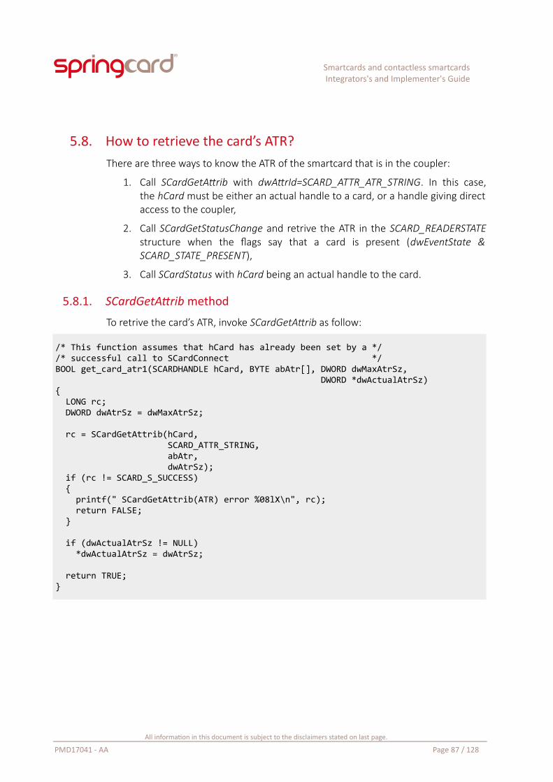
Smartcards and contactless smartcardsIntegrators's and Implementer's Guide
5.8. How to retrieve the card’s ATR?There are three ways to know the ATR of the smartcard that is in the coupler:
1. Call SCardGetAttrib with dwAttrId=SCARD_ATTR_ATR_STRING. In this case,the hCard must be either an actual handle to a card, or a handle giving directaccess to the coupler,
2. Call SCardGetStatusChange and retrive the ATR in the SCARD_READERSTATEstructure when the flags say that a card is present (dwEventState &SCARD_STATE_PRESENT),
3. Call SCardStatus with hCard being an actual handle to the card.
5.8.1. SCardGetAttrib method
To retrive the card’s ATR, invoke SCardGetAttrib as follow:
/* This function assumes that hCard has already been set by a *//* successful call to SCardConnect */BOOL get_card_atr1(SCARDHANDLE hCard, BYTE abAtr[], DWORD dwMaxAtrSz, DWORD *dwActualAtrSz){ LONG rc; DWORD dwAtrSz = dwMaxAtrSz;
rc = SCardGetAttrib(hCard, SCARD_ATTR_STRING, abAtr, dwAtrSz); if (rc != SCARD_S_SUCCESS) { printf(" SCardGetAttrib(ATR) error %08lX\n", rc); return FALSE; }
if (dwActualAtrSz != NULL) *dwActualAtrSz = dwAtrSz;
return TRUE;}
All information in this document is subject to the disclaimers stated on last page.
PMD17041 - AA Page 87 / 128
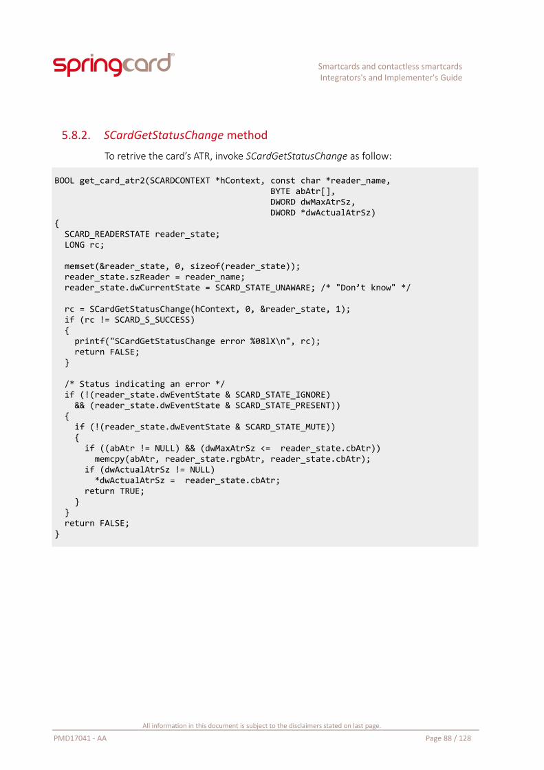
Smartcards and contactless smartcardsIntegrators's and Implementer's Guide
5.8.2. SCardGetStatusChange method
To retrive the card’s ATR, invoke SCardGetStatusChange as follow:
BOOL get_card_atr2(SCARDCONTEXT *hContext, const char *reader_name, BYTE abAtr[], DWORD dwMaxAtrSz, DWORD *dwActualAtrSz){ SCARD_READERSTATE reader_state; LONG rc;
memset(&reader_state, 0, sizeof(reader_state)); reader_state.szReader = reader_name; reader_state.dwCurrentState = SCARD_STATE_UNAWARE; /* "Don’t know" */
rc = SCardGetStatusChange(hContext, 0, &reader_state, 1); if (rc != SCARD_S_SUCCESS) { printf("SCardGetStatusChange error %08lX\n", rc); return FALSE; }
/* Status indicating an error */ if (!(reader_state.dwEventState & SCARD_STATE_IGNORE) && (reader_state.dwEventState & SCARD_STATE_PRESENT)) { if (!(reader_state.dwEventState & SCARD_STATE_MUTE)) { if ((abAtr != NULL) && (dwMaxAtrSz <= reader_state.cbAtr)) memcpy(abAtr, reader_state.rgbAtr, reader_state.cbAtr); if (dwActualAtrSz != NULL) *dwActualAtrSz = reader_state.cbAtr; return TRUE; } } return FALSE;}
All information in this document is subject to the disclaimers stated on last page.
PMD17041 - AA Page 88 / 128
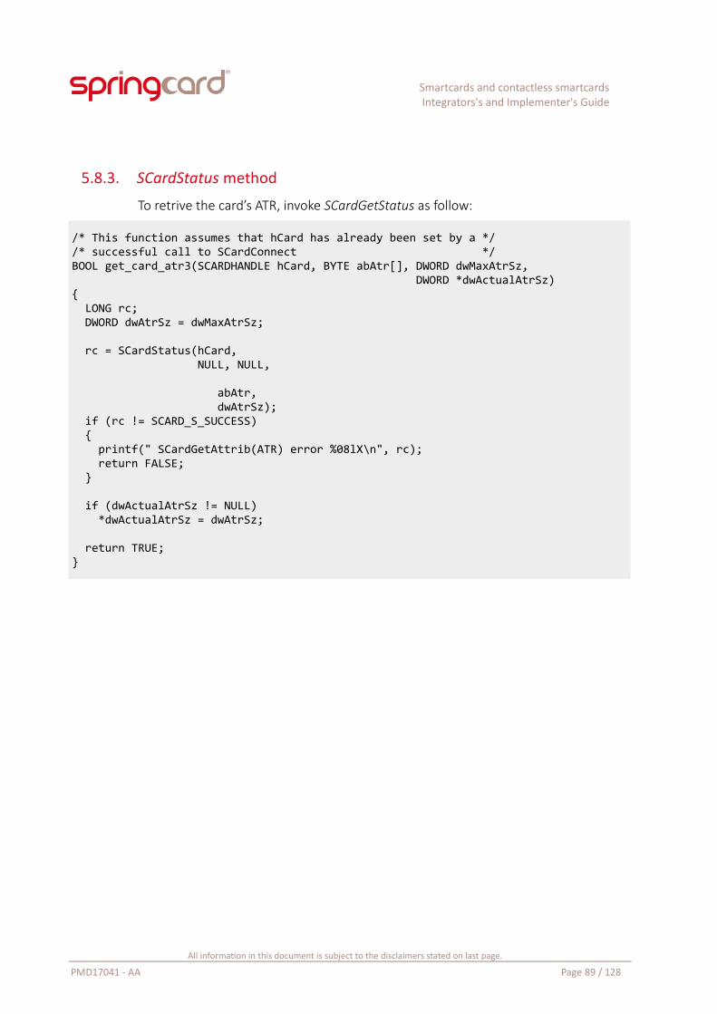
Smartcards and contactless smartcardsIntegrators's and Implementer's Guide
5.8.3. SCardStatus method
To retrive the card’s ATR, invoke SCardGetStatus as follow:
/* This function assumes that hCard has already been set by a *//* successful call to SCardConnect */BOOL get_card_atr3(SCARDHANDLE hCard, BYTE abAtr[], DWORD dwMaxAtrSz, DWORD *dwActualAtrSz){ LONG rc; DWORD dwAtrSz = dwMaxAtrSz;
rc = SCardStatus(hCard, NULL, NULL, abAtr, dwAtrSz); if (rc != SCARD_S_SUCCESS) { printf(" SCardGetAttrib(ATR) error %08lX\n", rc); return FALSE; }
if (dwActualAtrSz != NULL) *dwActualAtrSz = dwAtrSz;
return TRUE;}
All information in this document is subject to the disclaimers stated on last page.
PMD17041 - AA Page 89 / 128
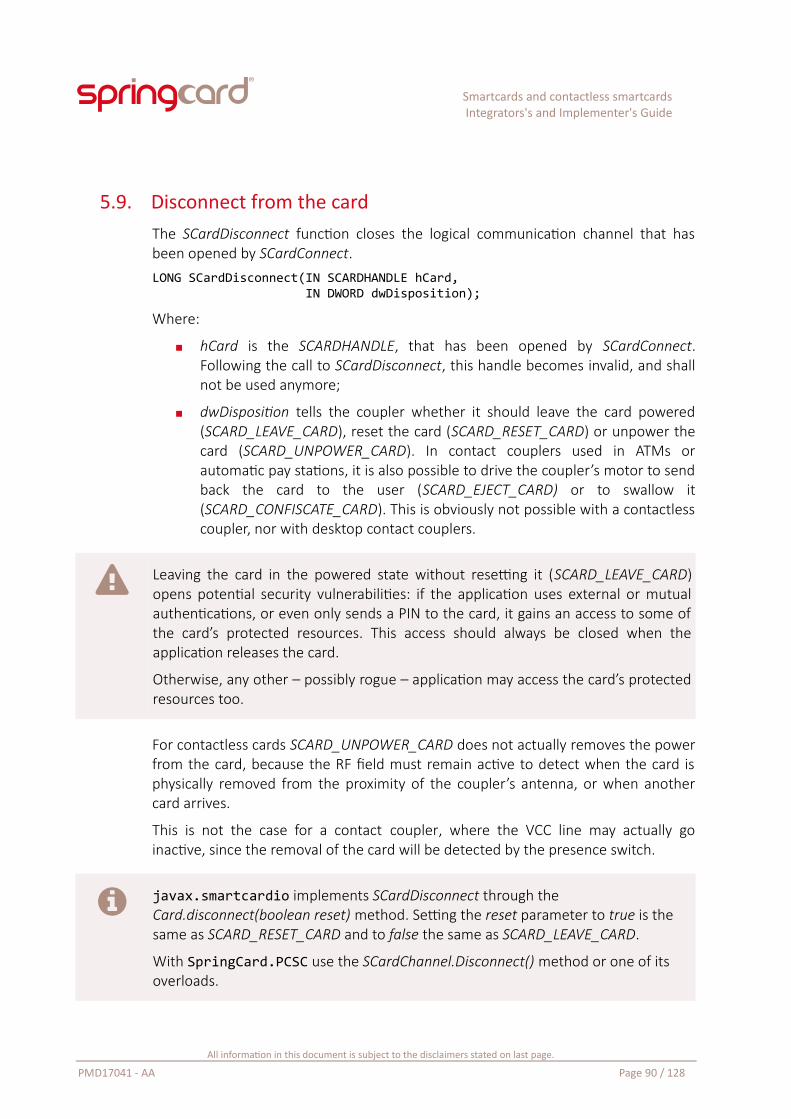
Smartcards and contactless smartcardsIntegrators's and Implementer's Guide
5.9. Disconnect from the cardThe SCardDisconnect function closes the logical communication channel that hasbeen opened by SCardConnect.LONG SCardDisconnect(IN SCARDHANDLE hCard, IN DWORD dwDisposition);
Where:
hCard is the SCARDHANDLE, that has been opened by SCardConnect.Following the call to SCardDisconnect, this handle becomes invalid, and shallnot be used anymore;
dwDisposition tells the coupler whether it should leave the card powered(SCARD_LEAVE_CARD), reset the card (SCARD_RESET_CARD) or unpower thecard (SCARD_UNPOWER_CARD). In contact couplers used in ATMs orautomatic pay stations, it is also possible to drive the coupler’s motor to sendback the card to the user (SCARD_EJECT_CARD) or to swallow it(SCARD_CONFISCATE_CARD). This is obviously not possible with a contactlesscoupler, nor with desktop contact couplers.
Leaving the card in the powered state without resetting it (SCARD_LEAVE_CARD)opens potential security vulnerabilities: if the application uses external or mutualauthentications, or even only sends a PIN to the card, it gains an access to some ofthe card’s protected resources. This access should always be closed when theapplication releases the card.
Otherwise, any other – possibly rogue – application may access the card’s protectedresources too.
For contactless cards SCARD_UNPOWER_CARD does not actually removes the powerfrom the card, because the RF field must remain active to detect when the card isphysically removed from the proximity of the coupler’s antenna, or when anothercard arrives.
This is not the case for a contact coupler, where the VCC line may actually goinactive, since the removal of the card will be detected by the presence switch.
javax.smartcardio implements SCardDisconnect through the Card.disconnect(boolean reset) method. Setting the reset parameter to true is the same as SCARD_RESET_CARD and to false the same as SCARD_LEAVE_CARD.
With SpringCard.PCSC use the SCardChannel.Disconnect() method or one of its overloads.
All information in this document is subject to the disclaimers stated on last page.
PMD17041 - AA Page 90 / 128
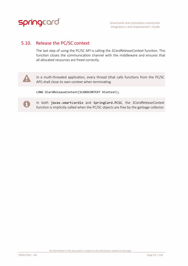
Smartcards and contactless smartcardsIntegrators's and Implementer's Guide
5.10. Release the PC/SC contextThe last step of using the PC/SC API is calling the SCardReleaseContext function. Thisfunction closes the communication channel with the middleware and ensures thatall allocated resources are freed correctly.
In a multi-threaded application, every thread (that calls functions from the PC/SCAPI) shall close its own context when terminating.
LONG SCardReleaseContext(SCARDCONTEXT hContext);
In both javax.smartcardio and SpringCard.PCSC, the SCardReleaseContextfunction is implicitly called when the PC/SC objects are free by the garbage collector.
All information in this document is subject to the disclaimers stated on last page.
PMD17041 - AA Page 91 / 128
Smartcards and contactless smartcardsIntegrators's and Implementer's Guide
6. Using contactless cards with PC/SC
6.1. IntroductionBy design, the standards and the PC/SC specification make it possible to operate anISO/IEC 7816-4 smartcard without even noticing whether it used the T=1 contacttransport protocol or the “T=CL” contactless transport protocol.
Unfortunately, when the contactless card is not compliant with ISO/IEC 7816-4 –which is obviously the case of RFID labels, most NFC Tags and most entry-levelcontactless cards – things are not that easy. The coupler’s embedded APDUProcessor exposes the card’s read and write functions through 7816-4 APDUs, butthis is not straightforward.
More than that, even the most classical 7816-4 smartcard may require some addedprecautions or efforts when operated over ISO/IEC 14443.
Indeed, for the user is free to remove the card from the RF field at any moment, thelikelihood of a fatal error during the transaction is lots higher in contactless modethan in contact mode. And, even if the transaction goes to the end, there is also astrong probability that the user removes the card and inserts it again – and in mostsituations this shall not start another transaction34.
The role of this chapter is to expose a few ideas that could dramatically increase theuser experience when correctly implemented by the application in the terminal.
6.2. Connecting to a contactless card
6.2.1. Protocol
We will see in next paragraph (6.4) that all contactless cards, either a wired-logiccard or an actual smartcard, has an ATR that tells the PC/SC middleware and stackthat the card does support both the T=0 and the T=1 protocols (TD1 and TD2 bytesof the ATR).
Since the card is said to support the two protocols, which one shall be selected bythe application when calling SCardConnect?
34 Imagine the situation where you are boarding a bus with a friend and intend to pay the two travels with your contactless transport card. You have to place the card in front of the validator twice to debit two tickets. If you remove the card too early, the validator instructs you present the card again – but it shall not start debiting a third ticket. And if you keep the cardin front of the validator, or even if you are shivering in front of it, it shall also not debit a third ticket. In other words, an ideal validator’s application should be able to make the difference, only by software, between the insert/remove/insert again sequence and the insert/shiver/shiver/shiver… sequence.
All information in this document is subject to the disclaimers stated on last page.
PMD17041 - AA Page 92 / 128
Smartcards and contactless smartcardsIntegrators's and Implementer's Guide
The answer is clear: the application shall always specify to use T=1 only, for (at least)two good reasons:
The ISO/IEC 14443-4 protocol is very close to T=1, and the card is allowed toreturn some data after any instruction (there is no difference between case 3and case 4 APDU: the LE byte is optional in contactless and GET RESPONSE isnot implemented). But if the card is connected in T=0 and returns some dataafter a case 3 APDU, this will be considered as a fatal protocol violation by thePC/SC middleware, and the answer will be lost.
The same applies for the coupler’s embedded APDU Processor, that isresponsible for exposing wired-logic cards through ISO/IEC 7816-4instructions. It uses the T=1 protocol only and makes no difference betweena case 3 and a case 4 APDU, which is considered to be a fatal violation of theT=0 protocol by the PC/SC middleware.
6.2.2. Share mode
There is another parameter that the application is responsible to choose whencalling SCardConnect: dwShareMode. This parameters tells whether the applicationaccepts to share the card with another application, or not.
It is never a good idea to share a smartcard – nor any security-sensitive resource.
If the application uses external or mutual authentications, or even only sends a PINto the card, it gains an access to some of the card’s protected resources. If theapplication accepts to share the card, any other – possibly rogue – application mayaccess the card’s protected resources too.
As a consequence, setting dwShareMode to SCARD_SHARE_EXCLUSIVE is the normalbehavior.
But this has a side effect: if another application is already connected to the card, thecall to SCardConnect in your application will fail with errorSCARD_E_SHARING_VIOLATION. And, on a standard Windows computer, the systemwill always be the first to connect to the card, in order to try and recognize it, withthe aim to find it suitable for one of its PC/SC helper libraries or smartcard mini-driver.
Therefore, your application must be designed to recover nicely from a sharingviolation, without any annoyance for the user.
All information in this document is subject to the disclaimers stated on last page.
PMD17041 - AA Page 93 / 128
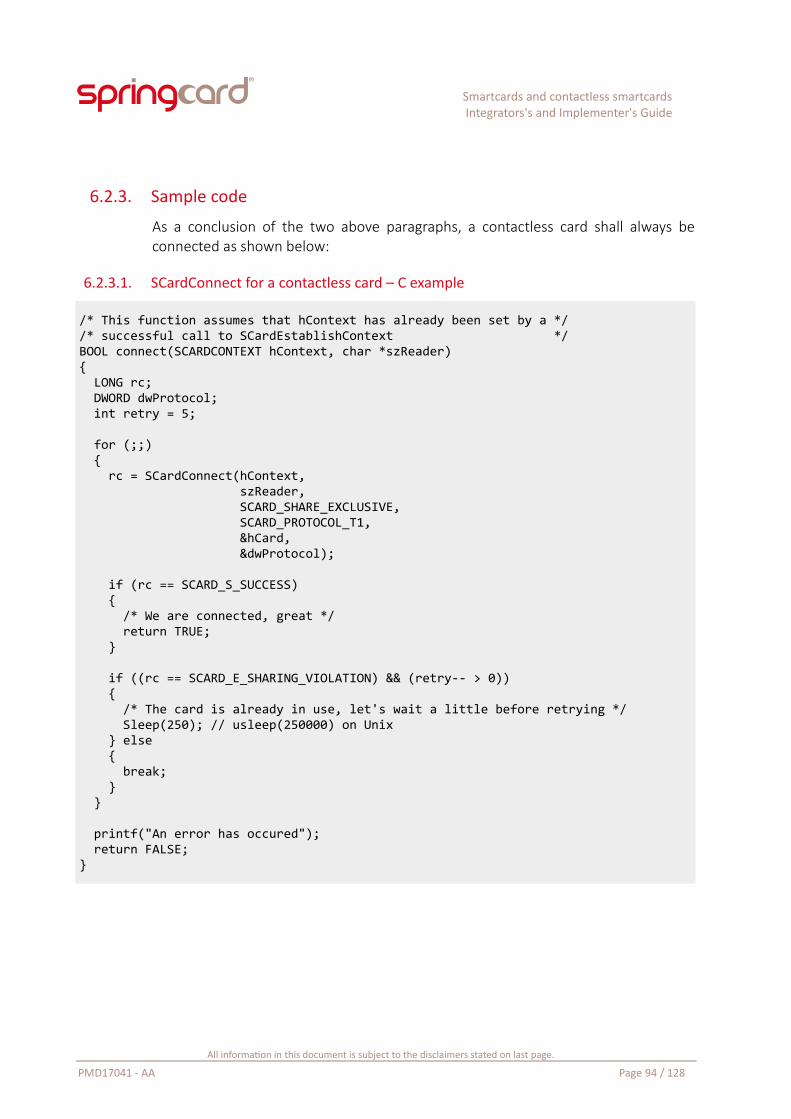
Smartcards and contactless smartcardsIntegrators's and Implementer's Guide
6.2.3. Sample code
As a conclusion of the two above paragraphs, a contactless card shall always beconnected as shown below:
6.2.3.1. SCardConnect for a contactless card – C example
/* This function assumes that hContext has already been set by a *//* successful call to SCardEstablishContext */BOOL connect(SCARDCONTEXT hContext, char *szReader){ LONG rc; DWORD dwProtocol; int retry = 5;
for (;;) { rc = SCardConnect(hContext, szReader, SCARD_SHARE_EXCLUSIVE, SCARD_PROTOCOL_T1, &hCard, &dwProtocol);
if (rc == SCARD_S_SUCCESS) { /* We are connected, great */ return TRUE; } if ((rc == SCARD_E_SHARING_VIOLATION) && (retry-- > 0)) { /* The card is already in use, let's wait a little before retrying */ Sleep(250); // usleep(250000) on Unix } else { break; } } printf("An error has occured"); return FALSE;}
All information in this document is subject to the disclaimers stated on last page.
PMD17041 - AA Page 94 / 128
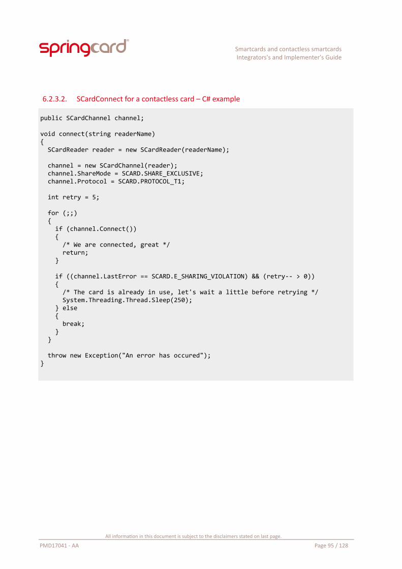
Smartcards and contactless smartcardsIntegrators's and Implementer's Guide
6.2.3.2. SCardConnect for a contactless card – C# example
public SCardChannel channel;
void connect(string readerName){ SCardReader reader = new SCardReader(readerName); channel = new SCardChannel(reader); channel.ShareMode = SCARD.SHARE_EXCLUSIVE; channel.Protocol = SCARD.PROTOCOL_T1; int retry = 5; for (;;) { if (channel.Connect()) { /* We are connected, great */ return; } if ((channel.LastError == SCARD.E_SHARING_VIOLATION) && (retry-- > 0)) { /* The card is already in use, let's wait a little before retrying */ System.Threading.Thread.Sleep(250); } else { break; } }
throw new Exception("An error has occured");}
All information in this document is subject to the disclaimers stated on last page.
PMD17041 - AA Page 95 / 128
Smartcards and contactless smartcardsIntegrators's and Implementer's Guide
6.3. Retrieving the card’s protocol level ID
6.3.1. Motivation
Whatever the low-level protocol in use (ISO/IEC 14443 A or B, ISO/IEC 15693, FeliCa,or any current vendor-specific implementation on top of a 13.56MHz carrier), thecard transmits an ID in response to the coupler’s lookup frames. This is the card’sprotocol level ID.
A lot of legacy applications use the protocol level ID of wired-logic contactlesscards are their primary source of information. This is a bad design, becausethe protocol level ID, being (of course) a publicly-readable data, is easy toclone on a card emulator, or even in an other card with “hacking” features35.Yet even new applications may have to re-use an existing architecture,whatever their design flaws,
Even if it is not the primary source of information, the protocol level ID isfrequently one of the key data. For instance, the data stored in the card mayinclude a digital signature computed over this ID, or the card’s authenticationkey(s) may be computed from a root key and this ID,
There is one more motivation of retrieving the card’s protocol level ID, andmaybe it is the most important with the user experience in mind: this ID tellsthe application whether it is ready to process the same card again, or theuser has inserted another. This is the basic feature to be able to restart aninterrupted transaction efficiently, or to prevent processing the same cardtwice.
There are nowadays a lot of inexpensive RFID/NFC “security investigation tools” thatallows to emulate virtually any PICC or VICC36, including cloning the ID and all thedata that the card contents.
Designing a secure solution starts by choosing a card chip providing strong securityfeatures (at least cryptographic-level authentication and message digest, possiblyciphered communication) and using them correctly.
35 For instance, it is easy to find on the web so-called “MIFARE Chinese Magic Cards”. The chip is a clone of NXP’s MIFARE Classic IC, but its protocol level ID could be written freely. This card is a scarecrow for a lots of legacy access control systems.
36 Google for: ProxMark iii and Chameleon RFID.
All information in this document is subject to the disclaimers stated on last page.
PMD17041 - AA Page 96 / 128
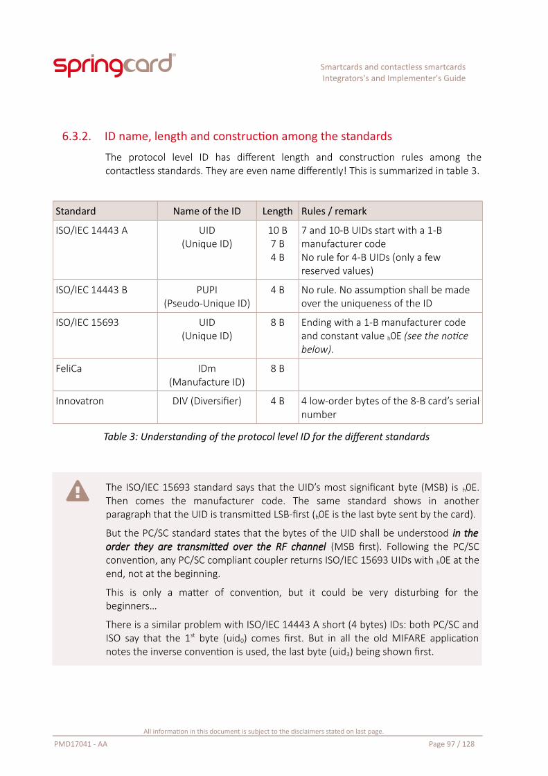
Smartcards and contactless smartcardsIntegrators's and Implementer's Guide
6.3.2. ID name, length and construction among the standards
The protocol level ID has different length and construction rules among thecontactless standards. They are even name differently! This is summarized in table 3.
Standard Name of the ID Length Rules / remark
ISO/IEC 14443 A UID(Unique ID)
10 B7 B4 B
7 and 10-B UIDs start with a 1-B manufacturer codeNo rule for 4-B UIDs (only a few reserved values)
ISO/IEC 14443 B PUPI(Pseudo-Unique ID)
4 B No rule. No assumption shall be made over the uniqueness of the ID
ISO/IEC 15693 UID(Unique ID)
8 B Ending with a 1-B manufacturer code and constant value h0E (see the notice below).
FeliCa IDm(Manufacture ID)
8 B
Innovatron DIV (Diversifier) 4 B 4 low-order bytes of the 8-B card’s serialnumber
Table 3: Understanding of the protocol level ID for the different standards
The ISO/IEC 15693 standard says that the UID’s most significant byte (MSB) is h0E.Then comes the manufacturer code. The same standard shows in anotherparagraph that the UID is transmitted LSB-first (h0E is the last byte sent by the card).
But the PC/SC standard states that the bytes of the UID shall be understood in theorder they are transmitted over the RF channel (MSB first). Following the PC/SCconvention, any PC/SC compliant coupler returns ISO/IEC 15693 UIDs with h0E at theend, not at the beginning.
This is only a matter of convention, but it could be very disturbing for thebeginners…
There is a similar problem with ISO/IEC 14443 A short (4 bytes) IDs: both PC/SC andISO say that the 1st byte (uid0) comes first. But in all the old MIFARE applicationnotes the inverse convention is used, the last byte (uid3) being shown first.
All information in this document is subject to the disclaimers stated on last page.
PMD17041 - AA Page 97 / 128
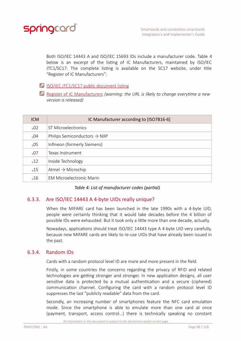
Smartcards and contactless smartcardsIntegrators's and Implementer's Guide
Both ISO/IEC 14443 A and ISO/IEC 15693 IDs include a manufacturer code. Table 4below is an excerpt of the listing of IC Manufacturers, maintained by ISO/IECJTC1/SC17. The complete listing is available on the SC17 website, under title“Register of IC Manufacturers”:
I SO/IEC JTC1/SC17 public document listing
Register of IC Manufacturers (warning: the URL is likely to change everytime a newversion is released)
ICM IC Manufacturer according to [ISO7816-6]
h02 ST Microelectronics
h04 Philips Semiconductors → NXP
h05 Infineon (formerly Siemens)
h07 Texas Instrument
h12 Inside Technology
h15 Atmel → Microchip
h16 EM Microelectronic Marin
Table 4: List of manufacturer codes (partial)
6.3.3. Are ISO/IEC 14443 A 4-byte UIDs really unique?
When the MIFARE card has been launched in the late 1990s with a 4-byte UID,people were certainly thinking that it would take decades before the 4 billion ofpossible IDs were exhausted. But it took only a little more than one decade, actually.
Nowadays, applications should treat ISO/IEC 14443 type A 4-byte UID very carefully,because new MIFARE cards are likely to re-use UIDs that have already been issued inthe past.
6.3.4. Random IDs
Cards with a random protocol level ID are more and more present in the field.
Firstly, in some countries the concerns regarding the privacy of RFID and relatedtechnologies are getting stronger and stronger. In new application designs, all usersensitive data is protected by a mutual authentication and a secure (ciphered)communication channel. Configuring the card with a random protocol level IDsuppresses the last “publicly readable” data from the card.
Secondly, an increasing number of smartphones feature the NFC card emulationmode. Since the smartphone is able to emulate more than one card at once(payment, transport, access control…) there is technically speaking no constant
All information in this document is subject to the disclaimers stated on last page.
PMD17041 - AA Page 98 / 128
Smartcards and contactless smartcardsIntegrators's and Implementer's Guide
protocol level ID to be exposed to the couplers. Given the privacy concerns, it hasbeen chosen to implement only random IDs in all today’s smartphones.
In ISO/IEC 14443 A, a random ID is a 4-B UID with the first byte set to h08.
In ISO/IEC 14443 B, any PUPI value could potentially be random.
The standards say that the card shall not change its ID while the RF field remainactive (in other words, the card should not generate a new random ID until it isexplicitly taken away from the coupler, and inserted again). Unfortunately, due to theintrinsic weakness of the communication link – including the movements from theuser – it is frequent that the coupler “sees” a card changing its ID after acommunication error. In the case of a smartphone, it may as well change its protocol(from ISO/IEC 14443 A to B, or from B to A) yet expose the very same applicationsand data.
Therefore, the application in the terminal must be adapted to identify the card basedon its private data, and not to rely on the protocol level data anymore.
6.3.5. The GET DATA (ID) instruction
The coupler’s embedded APDU Processor handles all instructions with the CLA byteset to hFF. Using the INS = hCA (GET DATA) and P1,P2 = h0000 it is possible to retrievethe card’s protocol level identifier.
All information in this document is subject to the disclaimers stated on last page.
PMD17041 - AA Page 99 / 128
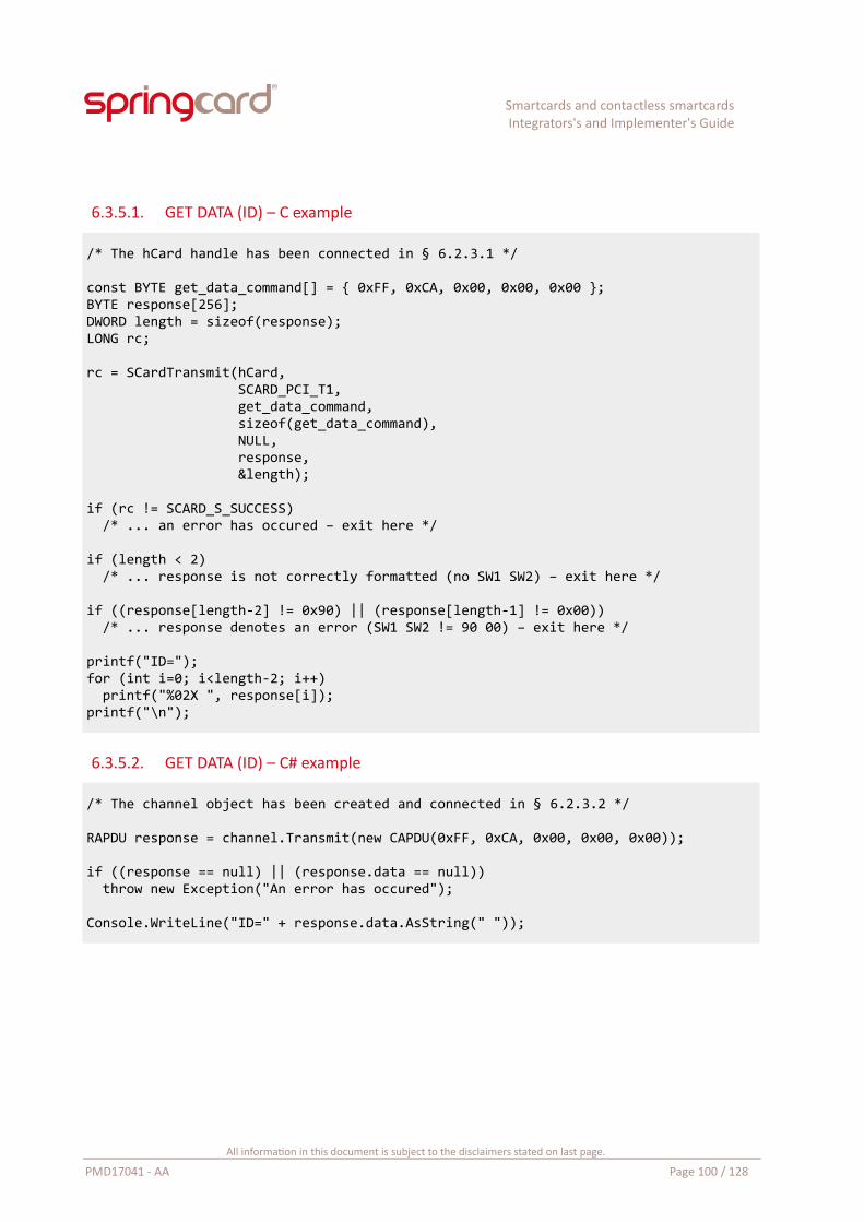
Smartcards and contactless smartcardsIntegrators's and Implementer's Guide
6.3.5.1. GET DATA (ID) – C example
/* The hCard handle has been connected in § 6.2.3.1 */
const BYTE get_data_command[] = { 0xFF, 0xCA, 0x00, 0x00, 0x00 };BYTE response[256];DWORD length = sizeof(response);LONG rc;
rc = SCardTransmit(hCard, SCARD_PCI_T1, get_data_command, sizeof(get_data_command), NULL, response, &length);
if (rc != SCARD_S_SUCCESS) /* ... an error has occured – exit here */
if (length < 2) /* ... response is not correctly formatted (no SW1 SW2) – exit here */
if ((response[length-2] != 0x90) || (response[length-1] != 0x00)) /* ... response denotes an error (SW1 SW2 != 90 00) – exit here */
printf("ID=");for (int i=0; i<length-2; i++) printf("%02X ", response[i]);printf("\n");
6.3.5.2. GET DATA (ID) – C# example
/* The channel object has been created and connected in § 6.2.3.2 */
RAPDU response = channel.Transmit(new CAPDU(0xFF, 0xCA, 0x00, 0x00, 0x00));
if ((response == null) || (response.data == null)) throw new Exception("An error has occured");
Console.WriteLine("ID=" + response.data.AsString(" "));
All information in this document is subject to the disclaimers stated on last page.
PMD17041 - AA Page 100 / 128
Smartcards and contactless smartcardsIntegrators's and Implementer's Guide
6.4. Recognizing the contactless card typeSome applications have to process different types of cards. Their first step is torecognize the card family, before branching to the appropriate workflow.
There are 2 ways of recognizing the card family:
Recognize, or analyze the card’s ATR. The ATR is the first frame sent over theserial line for a contact card, but for a contactless card, the ATR is a “virtual”frame that has to be constructed by the coupler; how is this ATR constructedis an important part of the PC/SC specification. Retrieving the ATR has alreadybeen dealt with in § 5.8. The understanding of the ATR’s data is the subject ofthe next paragraphs 6.4.1 and 6.4.2,
Connect to the card at first (SCardConnect) and reads its protocol data bysending the appropriate instruction to the embedded APDU Processor – andprocessing its response. This is the subject of paragraph 6.4.3.
All information in this document is subject to the disclaimers stated on last page.
PMD17041 - AA Page 101 / 128
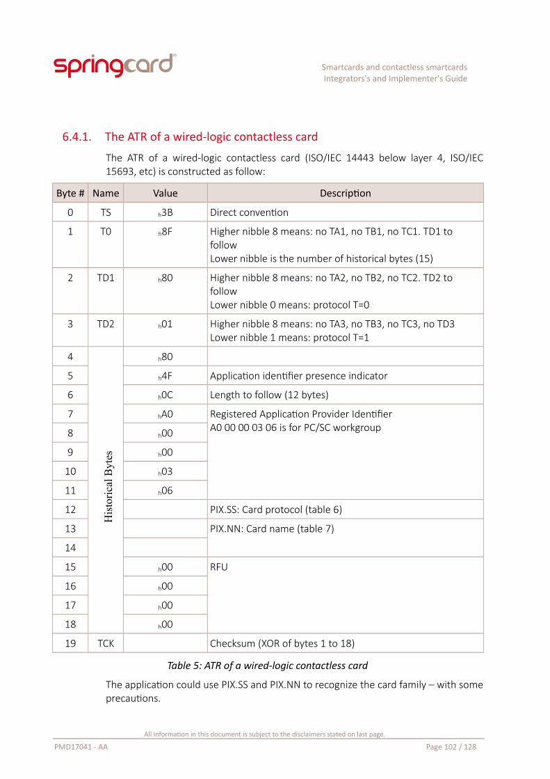
Smartcards and contactless smartcardsIntegrators's and Implementer's Guide
6.4.1. The ATR of a wired-logic contactless card
The ATR of a wired-logic contactless card (ISO/IEC 14443 below layer 4, ISO/IEC15693, etc) is constructed as follow:
Byte # Name Value Description
0 TS h3B Direct convention
1 T0 h8F Higher nibble 8 means: no TA1, no TB1, no TC1. TD1 to followLower nibble is the number of historical bytes (15)
2 TD1 h80 Higher nibble 8 means: no TA2, no TB2, no TC2. TD2 to followLower nibble 0 means: protocol T=0
3 TD2 h01 Higher nibble 8 means: no TA3, no TB3, no TC3, no TD3Lower nibble 1 means: protocol T=1
4 h80
5 h4F Application identifier presence indicator
6 h0C Length to follow (12 bytes)
7 hA0 Registered Application Provider IdentifierA0 00 00 03 06 is for PC/SC workgroup8 h00
9 h00
10 h03
11 h06
12 PIX.SS: Card protocol (table 6)
13 PIX.NN: Card name (table 7)
14
15 h00 RFU
16 h00
17 h00
18 h00
19 TCK Checksum (XOR of bytes 1 to 18)
Table 5: ATR of a wired-logic contactless card
The application could use PIX.SS and PIX.NN to recognize the card family – with someprecautions.
All information in this document is subject to the disclaimers stated on last page.
PMD17041 - AA Page 102 / 128
His
tori
cal B
ytes
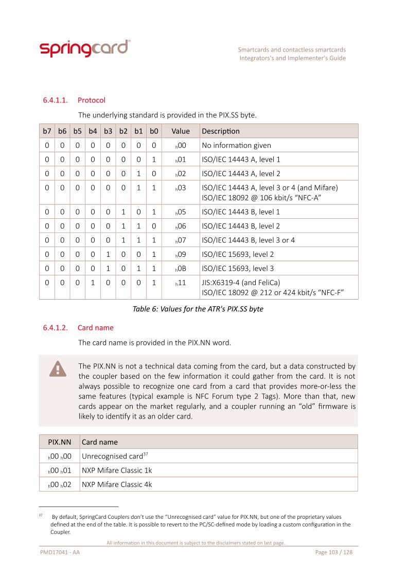
Smartcards and contactless smartcardsIntegrators's and Implementer's Guide
6.4.1.1. Protocol
The underlying standard is provided in the PIX.SS byte.
b7 b6 b5 b4 b3 b2 b1 b0 Value Description
0 0 0 0 0 0 0 0 h00 No information given
0 0 0 0 0 0 0 1 h01 ISO/IEC 14443 A, level 1
0 0 0 0 0 0 1 0 h02 ISO/IEC 14443 A, level 2
0 0 0 0 0 0 1 1 h03 ISO/IEC 14443 A, level 3 or 4 (and Mifare)ISO/IEC 18092 @ 106 kbit/s “NFC-A”
0 0 0 0 0 1 0 1 h05 ISO/IEC 14443 B, level 1
0 0 0 0 0 1 1 0 h06 ISO/IEC 14443 B, level 2
0 0 0 0 0 1 1 1 h07 ISO/IEC 14443 B, level 3 or 4
0 0 0 0 1 0 0 1 h09 ISO/IEC 15693, level 2
0 0 0 0 1 0 1 1 h0B ISO/IEC 15693, level 3
0 0 0 1 0 0 0 1 h11 JIS:X6319-4 (and FeliCa)ISO/IEC 18092 @ 212 or 424 kbit/s “NFC-F”
Table 6: Values for the ATR's PIX.SS byte
6.4.1.2. Card name
The card name is provided in the PIX.NN word.
The PIX.NN is not a technical data coming from the card, but a data constructed bythe coupler based on the few information it could gather from the card. It is notalways possible to recognize one card from a card that provides more-or-less thesame features (typical example is NFC Forum type 2 Tags). More than that, newcards appear on the market regularly, and a coupler running an “old” firmware islikely to identify it as an older card.
PIX.NN Card name
h00 h00 Unrecognised card37
h00 h01 NXP Mifare Classic 1k
h00 h02 NXP Mifare Classic 4k
37 By default, SpringCard Couplers don’t use the “Unrecognised card” value for PIX.NN, but one of the proprietary values defined at the end of the table. It is possible to revert to the PC/SC-defined mode by loading a custom configuration in the Coupler.
All information in this document is subject to the disclaimers stated on last page.
PMD17041 - AA Page 103 / 128
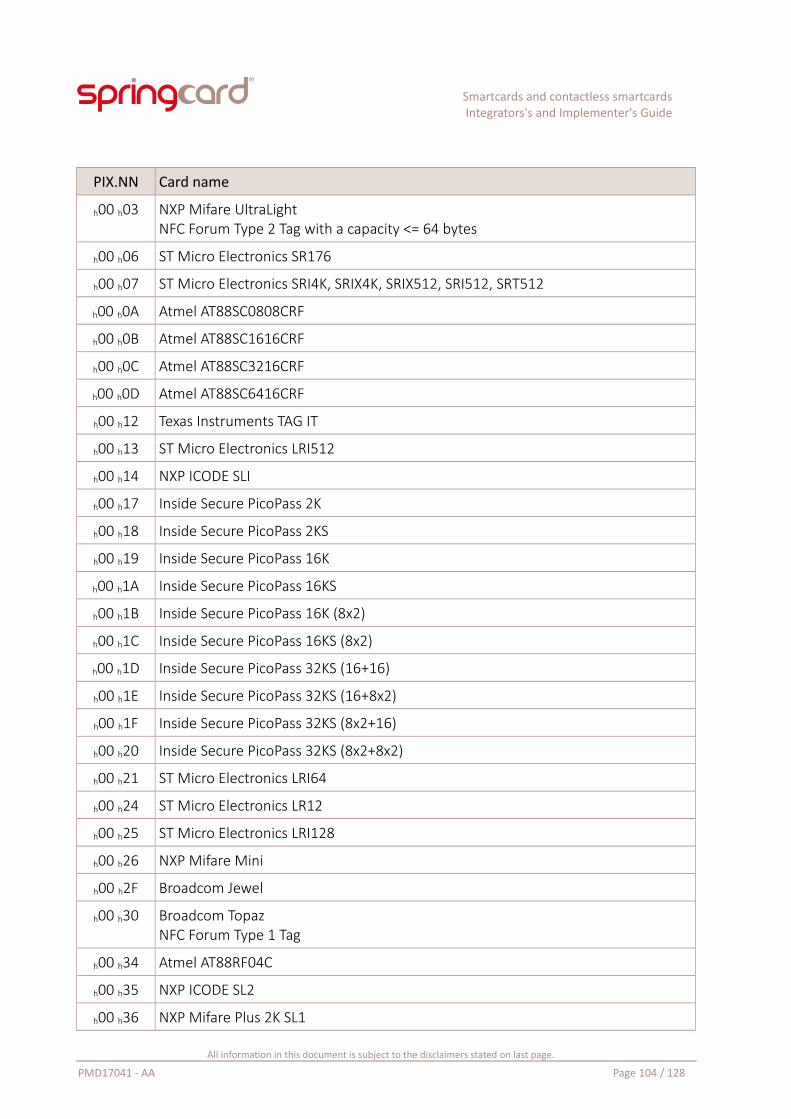
Smartcards and contactless smartcardsIntegrators's and Implementer's Guide
PIX.NN Card name
h00 h03 NXP Mifare UltraLightNFC Forum Type 2 Tag with a capacity <= 64 bytes
h00 h06 ST Micro Electronics SR176
h00 h07 ST Micro Electronics SRI4K, SRIX4K, SRIX512, SRI512, SRT512
h00 h0A Atmel AT88SC0808CRF
h00 h0B Atmel AT88SC1616CRF
h00 h0C Atmel AT88SC3216CRF
h00 h0D Atmel AT88SC6416CRF
h00 h12 Texas Instruments TAG IT
h00 h13 ST Micro Electronics LRI512
h00 h14 NXP ICODE SLI
h00 h17 Inside Secure PicoPass 2K
h00 h18 Inside Secure PicoPass 2KS
h00 h19 Inside Secure PicoPass 16K
h00 h1A Inside Secure PicoPass 16KS
h00 h1B Inside Secure PicoPass 16K (8x2)
h00 h1C Inside Secure PicoPass 16KS (8x2)
h00 h1D Inside Secure PicoPass 32KS (16+16)
h00 h1E Inside Secure PicoPass 32KS (16+8x2)
h00 h1F Inside Secure PicoPass 32KS (8x2+16)
h00 h20 Inside Secure PicoPass 32KS (8x2+8x2)
h00 h21 ST Micro Electronics LRI64
h00 h24 ST Micro Electronics LR12
h00 h25 ST Micro Electronics LRI128
h00 h26 NXP Mifare Mini
h00 h2F Broadcom Jewel
h00 h30 Broadcom TopazNFC Forum Type 1 Tag
h00 h34 Atmel AT88RF04C
h00 h35 NXP ICODE SL2
h00 h36 NXP Mifare Plus 2K SL1
All information in this document is subject to the disclaimers stated on last page.
PMD17041 - AA Page 104 / 128
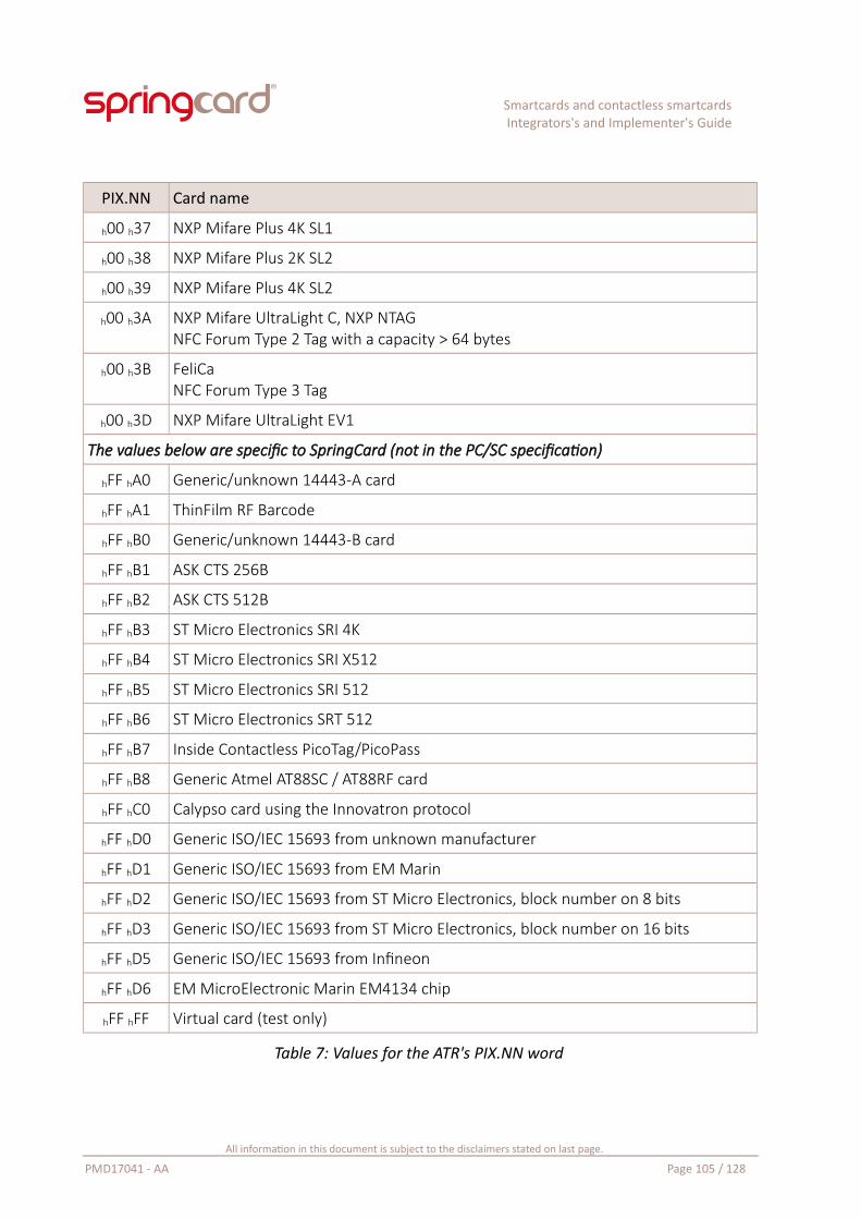
Smartcards and contactless smartcardsIntegrators's and Implementer's Guide
PIX.NN Card name
h00 h37 NXP Mifare Plus 4K SL1
h00 h38 NXP Mifare Plus 2K SL2
h00 h39 NXP Mifare Plus 4K SL2
h00 h3A NXP Mifare UltraLight C, NXP NTAGNFC Forum Type 2 Tag with a capacity > 64 bytes
h00 h3B FeliCaNFC Forum Type 3 Tag
h00 h3D NXP Mifare UltraLight EV1
The values below are specific to SpringCard (not in the PC/SC specification)
hFF hA0 Generic/unknown 14443-A card
hFF hA1 ThinFilm RF Barcode
hFF hB0 Generic/unknown 14443-B card
hFF hB1 ASK CTS 256B
hFF hB2 ASK CTS 512B
hFF hB3 ST Micro Electronics SRI 4K
hFF hB4 ST Micro Electronics SRI X512
hFF hB5 ST Micro Electronics SRI 512
hFF hB6 ST Micro Electronics SRT 512
hFF hB7 Inside Contactless PicoTag/PicoPass
hFF hB8 Generic Atmel AT88SC / AT88RF card
hFF hC0 Calypso card using the Innovatron protocol
hFF hD0 Generic ISO/IEC 15693 from unknown manufacturer
hFF hD1 Generic ISO/IEC 15693 from EM Marin
hFF hD2 Generic ISO/IEC 15693 from ST Micro Electronics, block number on 8 bits
hFF hD3 Generic ISO/IEC 15693 from ST Micro Electronics, block number on 16 bits
hFF hD5 Generic ISO/IEC 15693 from Infineon
hFF hD6 EM MicroElectronic Marin EM4134 chip
hFF hFF Virtual card (test only)
Table 7: Values for the ATR's PIX.NN word
All information in this document is subject to the disclaimers stated on last page.
PMD17041 - AA Page 105 / 128
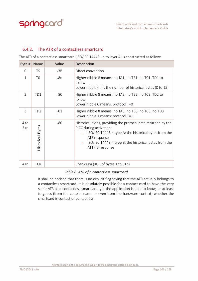
Smartcards and contactless smartcardsIntegrators's and Implementer's Guide
6.4.2. The ATR of a contactless smartcard
The ATR of a contactless smartcard (ISO/IEC 14443 up to layer 4) is constructed as follow:
Byte # Name Value Description
0 TS h3B Direct convention
1 T0 h8n Higher nibble 8 means: no TA1, no TB1, no TC1. TD1 to followLower nibble (n) is the number of historical bytes (0 to 15)
2 TD1 h80 Higher nibble 8 means: no TA2, no TB2, no TC2. TD2 to followLower nibble 0 means: protocol T=0
3 TD2 h01 Higher nibble 8 means: no TA3, no TB3, no TC3, no TD3Lower nibble 1 means: protocol T=1
4 to3+n
h80 Historical bytes, providing the protocol data returned by the PICC during activation:
• ISO/IEC 14443-4 type A: the historical bytes from the ATS response
• ISO/IEC 14443-4 type B: the historical bytes from the ATTRIB response
4+n TCK Checksum (XOR of bytes 1 to 3+n)
Table 8: ATR of a contactless smartcard
It shall be noticed that there is no explicit flag saying that the ATR actually belongs toa contactless smartcard. It is absolutely possible for a contact card to have the verysame ATR as a contactless smartcard, yet the application is able to know, or at leastto guess (from the coupler name or even from the hardware context) whether thesmartcard is contact or contactless.
All information in this document is subject to the disclaimers stated on last page.
PMD17041 - AA Page 106 / 128
His
tori
cal B
ytes
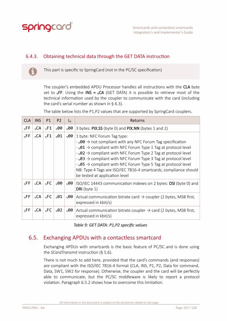
Smartcards and contactless smartcardsIntegrators's and Implementer's Guide
6.4.3. Obtaining technical data through the GET DATA instruction
This part is specific to SpringCard (not in the PC/SC specification)
The coupler’s embedded APDU Processor handles all instructions with the CLA byteset to hFF. Using the INS = hCA (GET DATA) it is possible to retrieve most of thetechnical information used by the coupler to communicate with the card (includingthe card’s serial number as shown in § 6.3).
The table below lists the P1,P2 values that are supported by SpringCard couplers.
CLA INS P1 P2 LE Returns
hFF hCA hF1 h00 h00 3 bytes: PIX.SS (byte 0) and PIX.NN (bytes 1 and 2)
hFF hCA hF1 h01 h00 1 byte: NFC Forum Tag type:- h00 → not compliant with any NFC Forum Tag specification- h01 → compliant with NFC Forum Type 1 Tag at protocol level- h02 → compliant with NFC Forum Type 2 Tag at protocol level- h03 → compliant with NFC Forum Type 3 Tag at protocol level- h05 → compliant with NFC Forum Type 5 Tag at protocol levelNB: Type 4 Tags are ISO/IEC 7816-4 smartcards, compliance shouldbe tested at application level
hFF hCA hFC h00 h00 ISO/IEC 14443 communication indexes on 2 bytes: DSI (byte 0) andDRI (byte 1)
hFF hCA hFC h01 h00 Actual communication bitrate card → coupler (2 bytes, MSB first, expressed in kbit/s)
hFF hCA hFC h02 h00 Actual communication bitrate coupler → card (2 bytes, MSB first, expressed in kbit/s)
Table 9: GET DATA: P1,P2 specific values
6.5. Exchanging APDUs with a contactless smartcardExchanging APDUs with smartcards is the basic feature of PC/SC and is done usingthe SCardTransmit instruction (§ 5.6).
There is not much to add here, provided that the card’s commands (and responses)are compliant with the ISO/IEC 7816-4 format (CLA, INS, P1, P2, Data for command,Data, SW1, SW2 for response). Otherwise, the coupler and the card will be perfectlyable to communicate, but the PC/SC middleware is likely to report a protocolviolation. Paragraph 6.5.2 shows how to overcome this limitation.
All information in this document is subject to the disclaimers stated on last page.
PMD17041 - AA Page 107 / 128
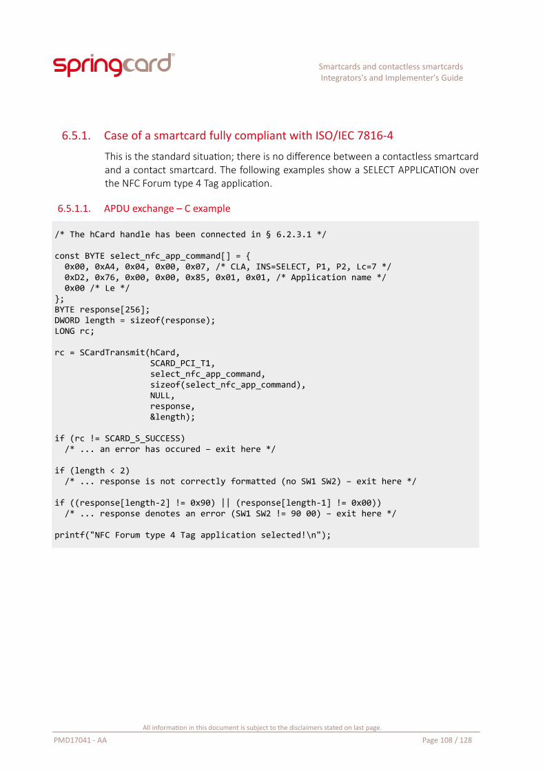
Smartcards and contactless smartcardsIntegrators's and Implementer's Guide
6.5.1. Case of a smartcard fully compliant with ISO/IEC 7816-4
This is the standard situation; there is no difference between a contactless smartcardand a contact smartcard. The following examples show a SELECT APPLICATION overthe NFC Forum type 4 Tag application.
6.5.1.1. APDU exchange – C example
/* The hCard handle has been connected in § 6.2.3.1 */
const BYTE select_nfc_app_command[] = { 0x00, 0xA4, 0x04, 0x00, 0x07, /* CLA, INS=SELECT, P1, P2, Lc=7 */ 0xD2, 0x76, 0x00, 0x00, 0x85, 0x01, 0x01, /* Application name */ 0x00 /* Le */};BYTE response[256];DWORD length = sizeof(response);LONG rc;
rc = SCardTransmit(hCard, SCARD_PCI_T1, select_nfc_app_command, sizeof(select_nfc_app_command), NULL, response, &length);
if (rc != SCARD_S_SUCCESS) /* ... an error has occured – exit here */
if (length < 2) /* ... response is not correctly formatted (no SW1 SW2) – exit here */
if ((response[length-2] != 0x90) || (response[length-1] != 0x00)) /* ... response denotes an error (SW1 SW2 != 90 00) – exit here */
printf("NFC Forum type 4 Tag application selected!\n");
All information in this document is subject to the disclaimers stated on last page.
PMD17041 - AA Page 108 / 128
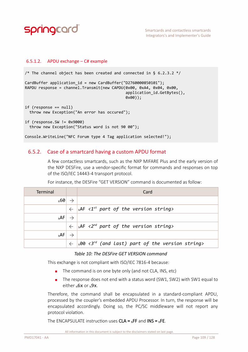
Smartcards and contactless smartcardsIntegrators's and Implementer's Guide
6.5.1.2. APDU exchange – C# example
/* The channel object has been created and connected in § 6.2.3.2 */
CardBuffer application_id = new CardBuffer("D2760000850101");RAPDU response = channel.Transmit(new CAPDU(0x00, 0xA4, 0x04, 0x00, application_id.GetBytes(), 0x00));
if (response == null) throw new Exception("An error has occured");
if (response.SW != 0x9000) throw new Exception("Status word is not 90 00");
Console.WriteLine("NFC Forum type 4 Tag application selected!");
6.5.2. Case of a smartcard having a custom APDU format
A few contactless smartcards, such as the NXP MIFARE Plus and the early version ofthe NXP DESFire, use a vendor-specific format for commands and responses on topof the ISO/IEC 14443-4 transport protocol.
For instance, the DESFire “GET VERSION” command is documented as follow:
Terminal Card
h60 →
← hAF <1st part of the version string>
hAF →
← hAF <2nd part of the version string>
hAF →
← h00 <3rd (and last) part of the version string>
Table 10: The DESFire GET VERSION command
This exchange is not compliant with ISO/IEC 7816-4 because:
The command is on one byte only (and not CLA, INS, etc)
The response does not end with a status word (SW1, SW2) with SW1 equal toeither h6x or h9x.
Therefore, the command shall be encapsulated in a standard-compliant APDU,processed by the coupler’s embedded APDU Processor. In turn, the response will beencapsulated accordingly. Doing so, the PC/SC middleware will not report anyprotocol violation.
The ENCAPSULATE instruction uses CLA = hFF and INS = hFE.
All information in this document is subject to the disclaimers stated on last page.
PMD17041 - AA Page 109 / 128
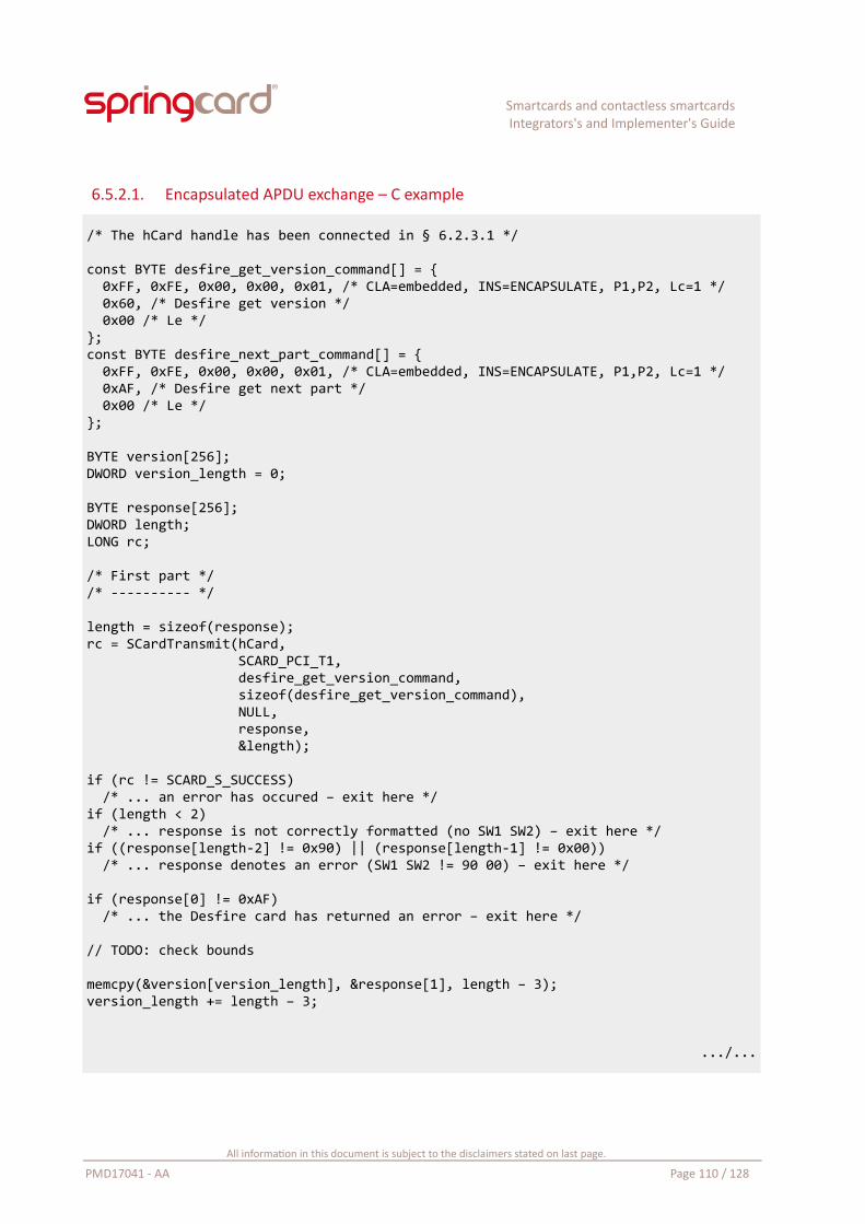
Smartcards and contactless smartcardsIntegrators's and Implementer's Guide
6.5.2.1. Encapsulated APDU exchange – C example
/* The hCard handle has been connected in § 6.2.3.1 */
const BYTE desfire_get_version_command[] = { 0xFF, 0xFE, 0x00, 0x00, 0x01, /* CLA=embedded, INS=ENCAPSULATE, P1,P2, Lc=1 */ 0x60, /* Desfire get version */ 0x00 /* Le */};const BYTE desfire_next_part_command[] = { 0xFF, 0xFE, 0x00, 0x00, 0x01, /* CLA=embedded, INS=ENCAPSULATE, P1,P2, Lc=1 */ 0xAF, /* Desfire get next part */ 0x00 /* Le */};
BYTE version[256];DWORD version_length = 0;
BYTE response[256];DWORD length;LONG rc;
/* First part *//* ---------- */
length = sizeof(response);rc = SCardTransmit(hCard, SCARD_PCI_T1, desfire_get_version_command, sizeof(desfire_get_version_command), NULL, response, &length);
if (rc != SCARD_S_SUCCESS) /* ... an error has occured – exit here */if (length < 2) /* ... response is not correctly formatted (no SW1 SW2) – exit here */if ((response[length-2] != 0x90) || (response[length-1] != 0x00)) /* ... response denotes an error (SW1 SW2 != 90 00) – exit here */
if (response[0] != 0xAF) /* ... the Desfire card has returned an error – exit here */
// TODO: check bounds
memcpy(&version[version_length], &response[1], length – 3);version_length += length – 3;
.../...
All information in this document is subject to the disclaimers stated on last page.
PMD17041 - AA Page 110 / 128
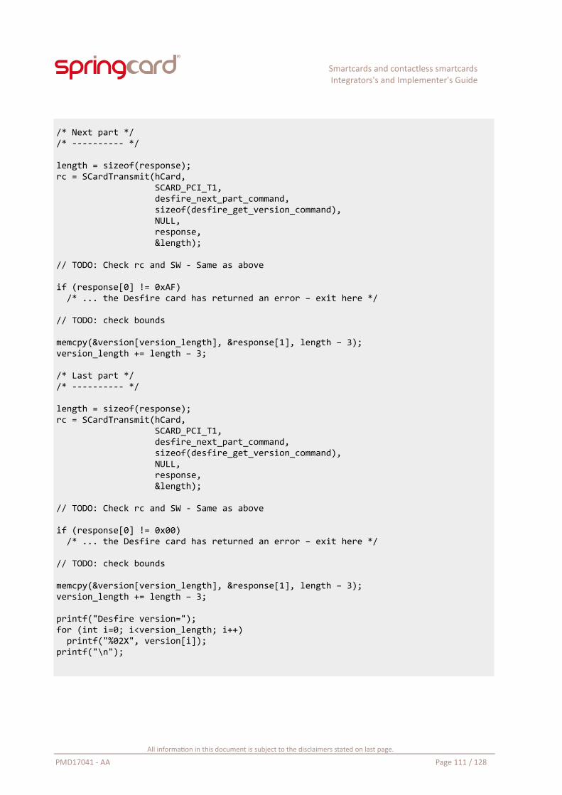
Smartcards and contactless smartcardsIntegrators's and Implementer's Guide
/* Next part *//* ---------- */
length = sizeof(response);rc = SCardTransmit(hCard, SCARD_PCI_T1, desfire_next_part_command, sizeof(desfire_get_version_command), NULL, response, &length);
// TODO: Check rc and SW - Same as above
if (response[0] != 0xAF) /* ... the Desfire card has returned an error – exit here */
// TODO: check bounds
memcpy(&version[version_length], &response[1], length – 3);version_length += length – 3;
/* Last part *//* ---------- */
length = sizeof(response);rc = SCardTransmit(hCard, SCARD_PCI_T1, desfire_next_part_command, sizeof(desfire_get_version_command), NULL, response, &length);
// TODO: Check rc and SW - Same as above
if (response[0] != 0x00) /* ... the Desfire card has returned an error – exit here */
// TODO: check bounds
memcpy(&version[version_length], &response[1], length – 3);version_length += length – 3;
printf("Desfire version=");for (int i=0; i<version_length; i++) printf("%02X", version[i]);printf("\n");
All information in this document is subject to the disclaimers stated on last page.
PMD17041 - AA Page 111 / 128
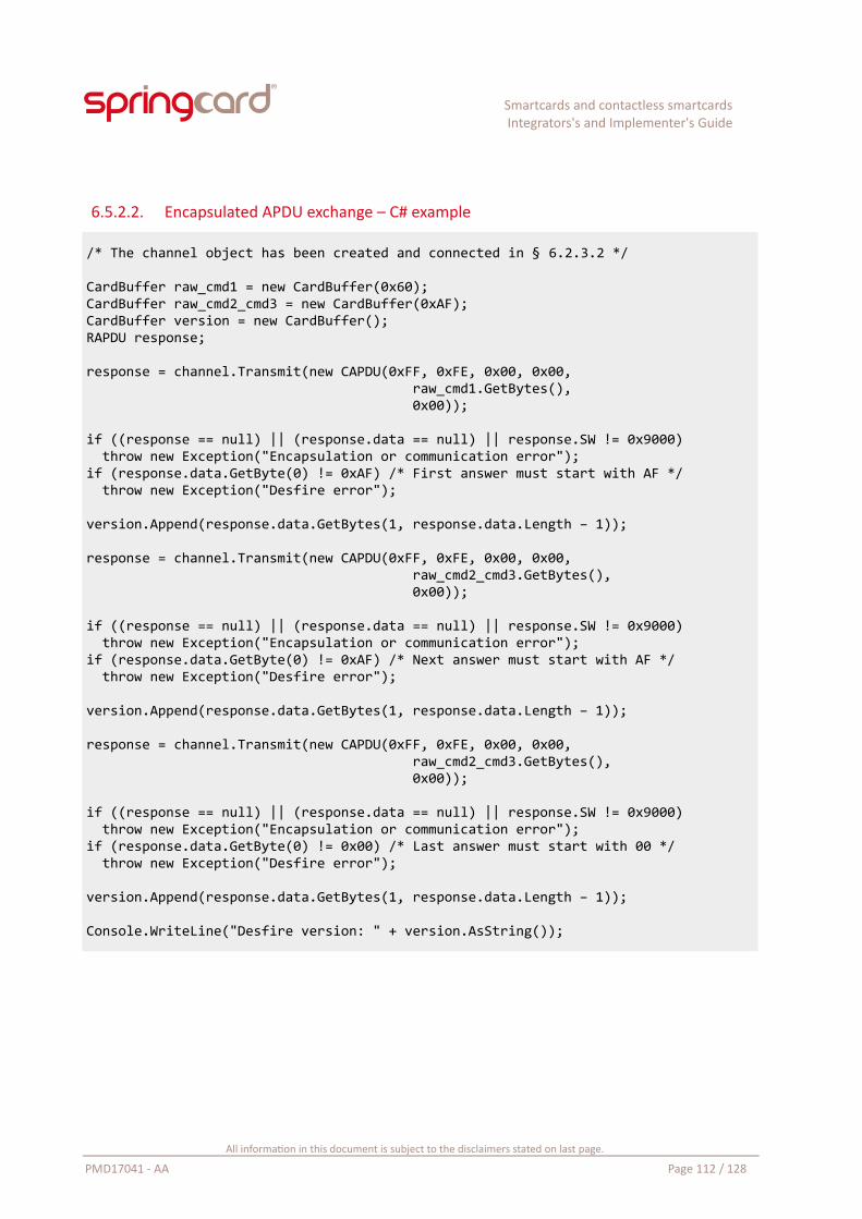
Smartcards and contactless smartcardsIntegrators's and Implementer's Guide
6.5.2.2. Encapsulated APDU exchange – C# example
/* The channel object has been created and connected in § 6.2.3.2 */
CardBuffer raw_cmd1 = new CardBuffer(0x60);CardBuffer raw_cmd2_cmd3 = new CardBuffer(0xAF);CardBuffer version = new CardBuffer();RAPDU response;
response = channel.Transmit(new CAPDU(0xFF, 0xFE, 0x00, 0x00, raw_cmd1.GetBytes(), 0x00));
if ((response == null) || (response.data == null) || response.SW != 0x9000) throw new Exception("Encapsulation or communication error");if (response.data.GetByte(0) != 0xAF) /* First answer must start with AF */ throw new Exception("Desfire error");
version.Append(response.data.GetBytes(1, response.data.Length – 1));
response = channel.Transmit(new CAPDU(0xFF, 0xFE, 0x00, 0x00, raw_cmd2_cmd3.GetBytes(), 0x00));
if ((response == null) || (response.data == null) || response.SW != 0x9000) throw new Exception("Encapsulation or communication error");if (response.data.GetByte(0) != 0xAF) /* Next answer must start with AF */ throw new Exception("Desfire error");
version.Append(response.data.GetBytes(1, response.data.Length – 1));
response = channel.Transmit(new CAPDU(0xFF, 0xFE, 0x00, 0x00, raw_cmd2_cmd3.GetBytes(), 0x00));
if ((response == null) || (response.data == null) || response.SW != 0x9000) throw new Exception("Encapsulation or communication error");if (response.data.GetByte(0) != 0x00) /* Last answer must start with 00 */ throw new Exception("Desfire error");
version.Append(response.data.GetBytes(1, response.data.Length – 1));
Console.WriteLine("Desfire version: " + version.AsString());
All information in this document is subject to the disclaimers stated on last page.
PMD17041 - AA Page 112 / 128
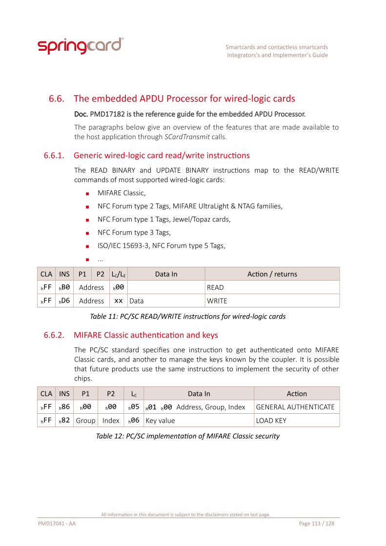
Smartcards and contactless smartcardsIntegrators's and Implementer's Guide
6.6. The embedded APDU Processor for wired-logic cardsDoc. PMD17182 is the reference guide for the embedded APDU Processor.
The paragraphs below give an overview of the features that are made available tothe host application through SCardTransmit calls.
6.6.1. Generic wired-logic card read/write instructions
The READ BINARY and UPDATE BINARY instructions map to the READ/WRITEcommands of most supported wired-logic cards:
MIFARE Classic,
NFC Forum type 2 Tags, MIFARE UltraLight & NTAG families,
NFC Forum type 1 Tags, Jewel/Topaz cards,
NFC Forum type 3 Tags,
ISO/IEC 15693-3, NFC Forum type 5 Tags,
...
CLA INS P1 P2 LC/LE Data In Action / returns
hFF hB0 Address h00 READ
hFF hD6 Address xx Data WRITE
Table 11: PC/SC READ/WRITE instructions for wired-logic cards
6.6.2. MIFARE Classic authentication and keys
The PC/SC standard specifies one instruction to get authenticated onto MIFAREClassic cards, and another to manage the keys known by the coupler. It is possiblethat future products use the same instructions to implement the security of otherchips.
CLA INS P1 P2 LC Data In Action
hFF h86 h00 h00 h05 H01 h00 Address, Group, Index GENERAL AUTHENTICATE
hFF h82 Group Index h06 Key value LOAD KEY
Table 12: PC/SC implementation of MIFARE Classic security
All information in this document is subject to the disclaimers stated on last page.
PMD17041 - AA Page 113 / 128
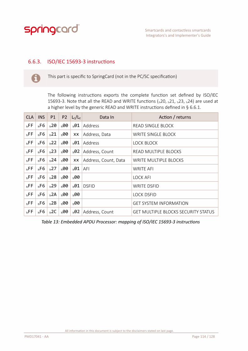
Smartcards and contactless smartcardsIntegrators's and Implementer's Guide
6.6.3. ISO/IEC 15693-3 instructions
This part is specific to SpringCard (not in the PC/SC specification)
The following instructions exports the complete function set defined by ISO/IEC15693-3. Note that all the READ and WRITE functions (h20, h21, h23, h24) are used ata higher level by the generic READ and WRITE instructions defined in § 6.6.1.
CLA INS P1 P2 LC/LE Data In Action / returns
hFF hF6 h20 h00 h01 Address READ SINGLE BLOCK
hFF hF6 h21 h00 xx Address, Data WRITE SINGLE BLOCK
hFF hF6 h22 h00 h01 Address LOCK BLOCK
hFF hF6 h23 h00 h02 Address, Count READ MULTIPLE BLOCKS
hFF hF6 h24 h00 xx Address, Count, Data WRITE MULTIPLE BLOCKS
hFF hF6 h27 h00 h01 AFI WRITE AFI
hFF hF6 h28 h00 h00 LOCK AFI
hFF hF6 h29 h00 h01 DSFID WRITE DSFID
hFF hF6 h2A h00 h00 LOCK DSFID
hFF hF6 h2B h00 h00 GET SYSTEM INFORMATION
hFF hF6 h2C h00 h02 Address, Count GET MULTIPLE BLOCKS SECURITY STATUS
Table 13: Embedded APDU Processor: mapping of ISO/IEC 15693-3 instructions
All information in this document is subject to the disclaimers stated on last page.
PMD17041 - AA Page 114 / 128
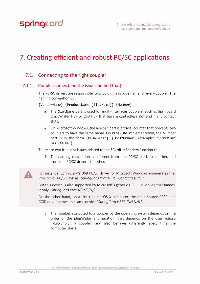
Smartcards and contactless smartcardsIntegrators's and Implementer's Guide
7. Creating efficient and robust PC/SC applications
7.1. Connecting to the right coupler
7.1.1. Coupler names (and the issues behind that)
The PC/SC drivers are responsible for providing a unique name for every coupler. Thenaming convention is:
{VendorName} {ProductName [SlotName]} {Number}
The SlotName part is used for multi-interfaces couplers, such as SpringCardCrazyWriter HSP or CSB HSP that have a contactless slot and many contactslots.
On Microsoft Windows, the Number part is a trivial counter that prevents twocouplers to have the same name. On PCSC-Lite implementation, the Numberpart is in the form {BusNumber} {UnitNumber} (example: “SpringCardH663 00 00”).
There are two frequent issues related to the SCardListReaders function call:
1. The naming convention is different from one PC/SC stack to another, andfrom one PC/SC driver to another.
For instance, SpringCard’s USB PC/SC driver for Microsoft Windows enumerates theProx’N’Roll PC/SC HSP as “SpringCard Prox’N’Roll Contactless {N}”.
But this device is also supported by Microsoft’s generic USB CCID driver, that namesit only “SpringCard Prox’N’Roll {N}”.
On the other hand, on a Linux or macOS X computer, the open source PCSC-LiteCCID driver names the same device “SpringCard H663 {NN NN}”.
2. The number attributed to a coupler by the operating system depends on theorder of the plug’n’play enumeration, that depends on the user actions(plug/unplug a coupler) and also behaves differently every time thecomputer starts.
All information in this document is subject to the disclaimers stated on last page.
PMD17041 - AA Page 115 / 128
Smartcards and contactless smartcardsIntegrators's and Implementer's Guide
Suppose you connect two Prox’N’Roll HSP PC/SC to your running computer, oneafter the other. The first one will be named “SpringCard Prox’N’Roll Contactless 0”,and the second one “SpringCard Prox’N’Roll Contactless 1”.
Now reboot the computer. You will have two couplers bearing the same name, butthere is a 50% chance that they have been swapped.
As a consequence, any application where the coupler’s name is hard-coded is likelyto fail on some computers or when another PC/SC device is added to the computer.
To avoid any problem, after calling SCardListReaders, the application shall either:
Always present a list of the currently available couplers to the user (in a drop-down list or so), and let the user decide which coupler he wants to use,
“Guess” which one is the most suitable coupler and select this couplerautomatically (see next paragraph 7.1.2 for a possible strategy),
Select the coupler based on its serial number (and store this serial number,not the coupler’s name, in the application persistent settings). Paragraph 5.7shows how to retrieve the coupler’s serial number,
Monitor all the couplers, and try to recognize the card(s) that the applicationsupports, based on the ATR. Paragraph 5.8.2 shows how to useSCardGetStatusChange to get notified when a card arrives in any coupler andobtain its ATR
7.1.2. Identifying a SpringCard PC/SC contactless coupler
Use the following algorithm to select the first SpringCard PC/SC contactless coupler:
Create a lower case copy of the coupler’s name,
Does this string starts with “springcard”?→ this is a SpringCard PC/SC coupler
Does this string contains “contactless” or “nfc”?→ this is the contactless slot of the SpringCard PC/SC coupler, on a Windows system and using the driver supplied by SpringCard,
Does this string ends with “00”?→ this is the first slot, hence the contactless slot, of the SpringCard PC/SC coupler, on a PCSC-Lite system,
Else:→ this is the only slot, hence the contactless slot, of the SpringCard PC/SC coupler, on a Windows system and using the driver supplied by Microsoft.
All information in this document is subject to the disclaimers stated on last page.
PMD17041 - AA Page 116 / 128
Smartcards and contactless smartcardsIntegrators's and Implementer's Guide
7.2. Using background threadsBy default, application code runs in the main thread. Every statement is thereforeexecuted in sequence. If you perform a long lasting operation, the application blocksuntil the corresponding operation has finished.
Any I/O operation that could potentially take more than a few milliseconds to runshould be executed in a background thread, to prevent any “lag” or blocking of theapplication’s window, which is a very bad user experience.
Although most smartcard-related I/O operations (SCardConnect, SCardTransmit) willtake only a few milliseconds in most situations, there are some situations where theycould block up to a few seconds, maybe up to one minute38.
Therefore, a windowed application should always implement the smartcard-relatedI/O operations in a background thread.
The need to implement nicely “long lasting” tasks more easily from the developer’s point of view has led to the introduction of thread pools and/or to an asynchronous programming paradigm in modern development languages.
Next version SpringCard.PCSC will allow using the async/await keywords of the .NET environment.
7.2.1. Monitoring the coupler(s) and card(s) in background
Using SCardConnect as shown in paragraph 5.4 “Is there a card in the coupler?” isnot very satisfying, nor is it efficient to say the least.
In a naive implementation, it relies on the user repeatedly clicking on a “start”button until the card is there, and the transaction could actually start.
Moving to an unattended implementation means calling SCardConnect periodically,from a software timer, until it returns SCARD_S_SUCCESS – OK.
But if the timer is too fast, its a pure waste of computer resources – and if it is tooslow, a significant delay is introduced between the insertion of the card and thebeginning of the transaction.
Fortunately, the PC/SC API offers the SCardGetStatusChange function, that, despitethe lack of ‘Wait’ in the name, is a blocking call, with a timeout. The caller stopsconsuming any resource, and is resumed by the middleware only when the couplerfires an event. SCardConnect may then be called only when a card has just beeninserted.
A few other events are also fired by the middleware to ease the synchronisationbetween two or more applications: an application waiting on SCardGetStatusChange
38 See examples in § 7.2.3.
All information in this document is subject to the disclaimers stated on last page.
PMD17041 - AA Page 117 / 128
Smartcards and contactless smartcardsIntegrators's and Implementer's Guide
is notified when another application gains access to the card, and when the card ismade available again.
But as any other blocking function, SCardGetStatusChange shall never be called fromthe application’s main thread.
Therefore, a card-aware application using SCardGetStatusChange shall alwaysimplement this function call in a background thread.
7.2.2. SCardConnect “loop” in the background
As we have seen in paragraph 6.2.3, the application must be ready to retry its call toSCardConnect if the card is used by another application. This is done by catching theSCARD_E_SHARING_VIOLATION error and retrying after a few hundreds ofmilliseconds.
Therefore, this SCardConnect + Sleep loop shall be implemented in a backgroundthread for a correct user experience.
7.2.3. SCardTransmit in the background
Even if the execution of a typical command by a smartcard is rather fast, there aresome situations where it could be dramatically slow:
In the contactless world, an ISO/IEC 14443-4 smartcard may report that itneeds more than 5 seconds to process a command. If the user removes sucha card while there is a running command, the coupler will wait for a first 5-second timeout. The coupler will then run its error-recovery algorithm, whichinvolve retrying up to 3 times. As a consequence, such a card will be reportedas removed only after 20 seconds or so;
In the contact world, some (old) cryptographic cards take up to 60 secondsonly to generate a new RSA key-pair.
And, more than that, a typical card transaction involves more than one exchanges.Even if every exchange take only 20ms or so, a sequence of 50 exchanges is already1s in best case.
Therefore, the sequence of SCardTransmit that represent a card transaction shall beimplemented in a background thread for a correct user experience.
All information in this document is subject to the disclaimers stated on last page.
PMD17041 - AA Page 118 / 128
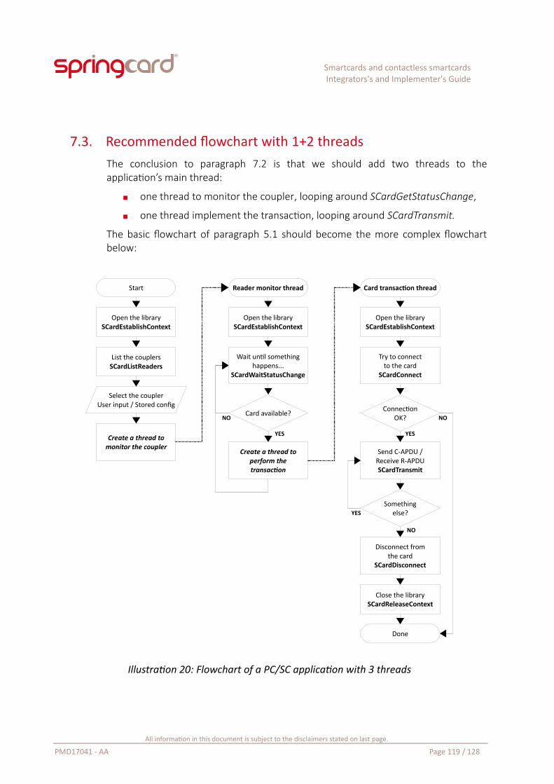
Smartcards and contactless smartcardsIntegrators's and Implementer's Guide
7.3. Recommended flowchart with 1+2 threadsThe conclusion to paragraph 7.2 is that we should add two threads to theapplication’s main thread:
one thread to monitor the coupler, looping around SCardGetStatusChange,
one thread implement the transaction, looping around SCardTransmit.
The basic flowchart of paragraph 5.1 should become the more complex flowchartbelow:
Illustration 20: Flowchart of a PC/SC application with 3 threads
All information in this document is subject to the disclaimers stated on last page.
PMD17041 - AA Page 119 / 128
Start
Open the librarySCardEstablishContext
List the couplersSCardListReaders
Select the couplerUser input / Stored config
Create a thread tomonitor the coupler
Wait until somethinghappens...
SCardWaitStatusChange
Reader monitor thread
Open the librarySCardEstablishContext
Card available?
YES
NO
Create a thread toperform thetransaction
Card transaction thread
Open the librarySCardEstablishContext
Try to connectto the card
SCardConnect
ConnectionOK?
Send C-APDU /Receive R-APDUSCardTransmit
Somethingelse?
Close the librarySCardReleaseContext
Disconnect fromthe card
SCardDisconnect
Done
NO
YES
YES
NO
Smartcards and contactless smartcardsIntegrators's and Implementer's Guide
There are a few things worth noticing in this flowchart:
Every thread gets its own handle to the library by callingSCardEstablishContext. This is mandatory in PCSC-Lite, and considered a goodpractice on Windows too. Otherwise, the application can not stop thebackground threads individually.
Actually, the flowchart doesn’t show either how the Reader monitor threadand the Card transaction thread could be stopped. There is a single functionto do so: SCardCancel. Just call SCardCancel from the main thread, providingas single parameter the hContext belonging to the thread you want to stop.Any blocking call (SCardWaitStatusChange, long SCardTransmit) willterminate with error SCARD_E_CANCELLED. That is why you should have asingle hContext for every thread.
The flowchart doesn’t show either how the Reader monitor thread and theCard transaction thread interact with the user. This is often the most trickypart in such a windowed-application, because the GUI belongs to the mainthread, and the background threads must use callbacks (or messages, ordelegates) to have the main thread manipulate the GUI for them. If you arenot familiar with this concept, read this page at Microsoft’s:
https://docs.microsoft.com/en-us/dotnet/standard/asynchronous-programming-patterns/calling-synchronous-methods-asynchronously
7.4. Understanding the errors (and implementing a smart recovery)The PC/SC API defines a lot of errors. It is not in the aim of this guide to document allof them. Nevertheless, the developer will find in the tables some tips to understand– and avoid – a few frequent mistakes, or to correctly handle “user related” errors.
All information in this document is subject to the disclaimers stated on last page.
PMD17041 - AA Page 120 / 128
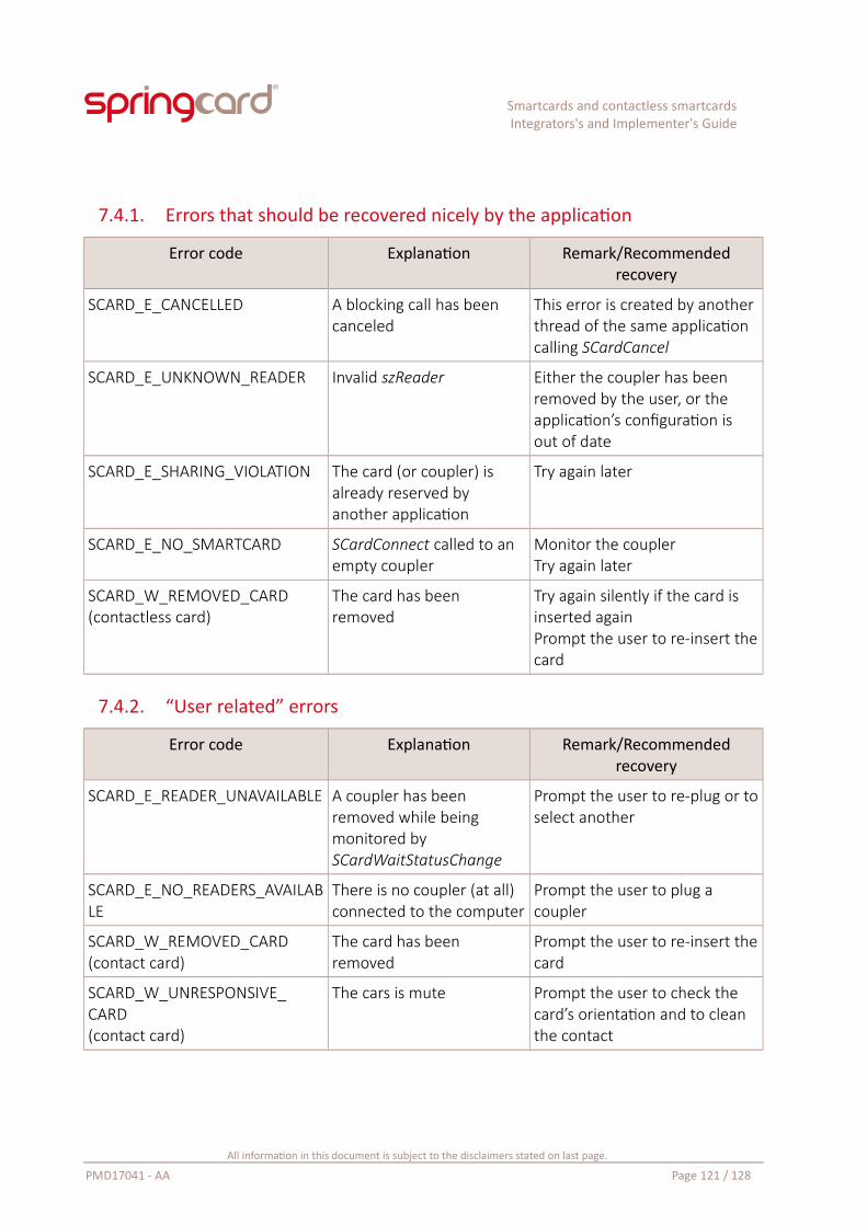
Smartcards and contactless smartcardsIntegrators's and Implementer's Guide
7.4.1. Errors that should be recovered nicely by the application
Error code Explanation Remark/Recommendedrecovery
SCARD_E_CANCELLED A blocking call has been canceled
This error is created by another thread of the same application calling SCardCancel
SCARD_E_UNKNOWN_READER Invalid szReader Either the coupler has been removed by the user, or the application’s configuration is out of date
SCARD_E_SHARING_VIOLATION The card (or coupler) is already reserved by another application
Try again later
SCARD_E_NO_SMARTCARD SCardConnect called to an empty coupler
Monitor the couplerTry again later
SCARD_W_REMOVED_CARD(contactless card)
The card has been removed
Try again silently if the card is inserted againPrompt the user to re-insert thecard
7.4.2. “User related” errors
Error code Explanation Remark/Recommendedrecovery
SCARD_E_READER_UNAVAILABLE A coupler has been removed while being monitored by SCardWaitStatusChange
Prompt the user to re-plug or toselect another
SCARD_E_NO_READERS_AVAILABLE
There is no coupler (at all) connected to the computer
Prompt the user to plug a coupler
SCARD_W_REMOVED_CARD(contact card)
The card has been removed
Prompt the user to re-insert thecard
SCARD_W_UNRESPONSIVE_CARD(contact card)
The cars is mute Prompt the user to check the card’s orientation and to clean the contact
All information in this document is subject to the disclaimers stated on last page.
PMD17041 - AA Page 121 / 128
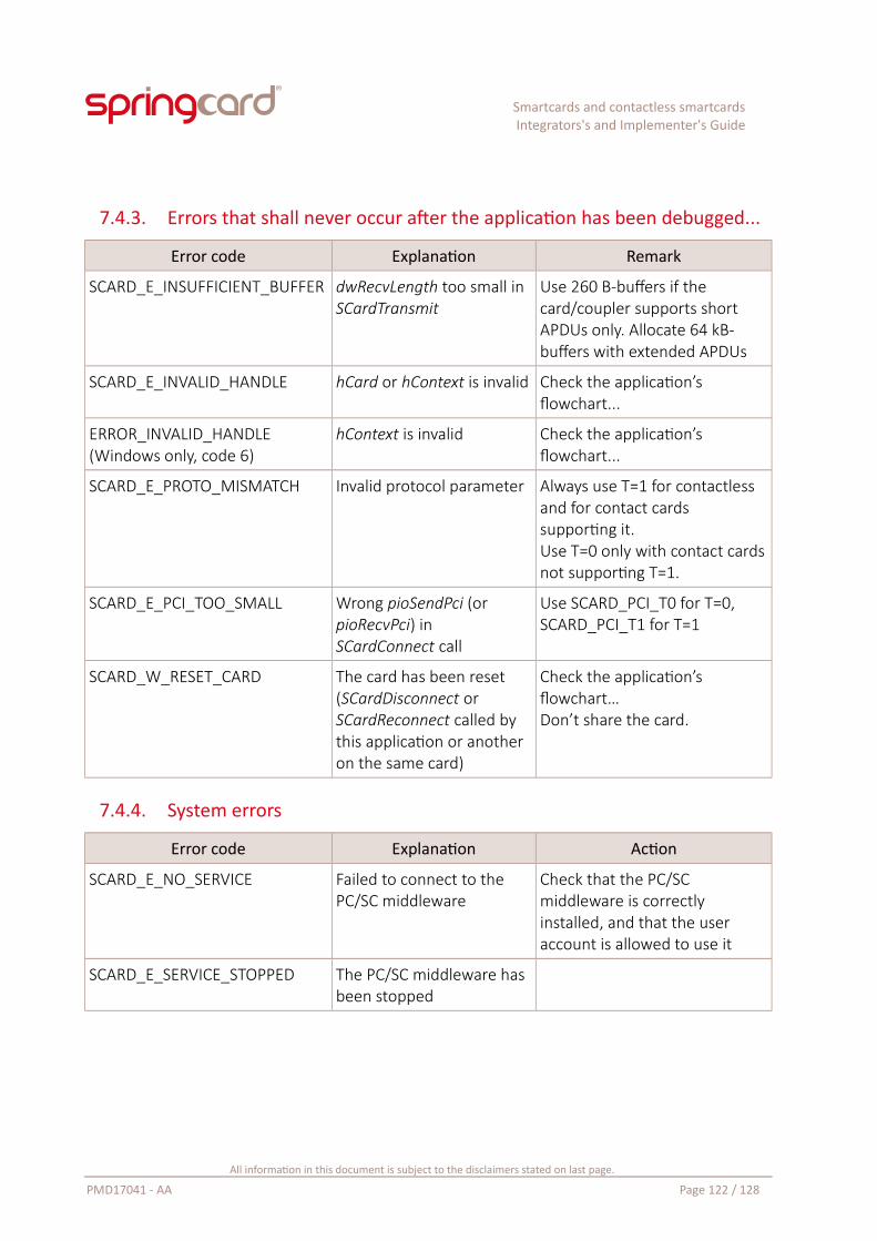
Smartcards and contactless smartcardsIntegrators's and Implementer's Guide
7.4.3. Errors that shall never occur after the application has been debugged...
Error code Explanation Remark
SCARD_E_INSUFFICIENT_BUFFER dwRecvLength too small in SCardTransmit
Use 260 B-buffers if the card/coupler supports short APDUs only. Allocate 64 kB-buffers with extended APDUs
SCARD_E_INVALID_HANDLE hCard or hContext is invalid Check the application’s flowchart...
ERROR_INVALID_HANDLE(Windows only, code 6)
hContext is invalid Check the application’s flowchart...
SCARD_E_PROTO_MISMATCH Invalid protocol parameter Always use T=1 for contactless and for contact cards supporting it.Use T=0 only with contact cardsnot supporting T=1.
SCARD_E_PCI_TOO_SMALL Wrong pioSendPci (or pioRecvPci) in SCardConnect call
Use SCARD_PCI_T0 for T=0, SCARD_PCI_T1 for T=1
SCARD_W_RESET_CARD The card has been reset (SCardDisconnect or SCardReconnect called by this application or another on the same card)
Check the application’s flowchart…Don’t share the card.
7.4.4. System errors
Error code Explanation Action
SCARD_E_NO_SERVICE Failed to connect to the PC/SC middleware
Check that the PC/SC middleware is correctly installed, and that the user account is allowed to use it
SCARD_E_SERVICE_STOPPED The PC/SC middleware has been stopped
All information in this document is subject to the disclaimers stated on last page.
PMD17041 - AA Page 122 / 128
Smartcards and contactless smartcardsIntegrators's and Implementer's Guide
8. Smartcard applications without PC/SC
Developing a smartcard-aware application is not limited to high-end operatingsystems, such as Microsoft Windows, Linux or macOS X. In many OEM integrations,SpringCard couplers are driven by an industrial PLC or maybe a microcontrollerunable to run a complete PC/SC stack. There is also the case of Android, wherePC/SC is not available on mainstream devices.
More than that, even on a high-end host, the PC/SC driver and middleware aresoftware layers that provide useful services, but at the price of a significant overheadthat increases the time it takes to perform a transaction with the card. In suchsituation, notably when the coupler uses a simple serial or TCP channel tocommunicate, it could be more efficient to drive the coupler directly from theapplication. This is of course an added complexity for the developer, but objectoriented programming allows to mask this complexity somehow.
This chapter introduces two architectures that are used by SpringCard in differentprojects as an alternative to a “genuine” PC/SC stack.
8.1. SpringCard zero-driver CCID implementationDoc. PMD15282 is the reference guide for the zero-driver CCID implementation.
CCID is the USB specification for Chip Card Interface Devices. In clear words, it is arecommended protocol for implementers of USB-attached PC/SC couplers.
SpringCard not only uses this protocol in all its USB couplers, but also uses CCID asthe foundation of the communication protocols created over other mediums: TCP,serial, and even Bluetooth Smart (also known as BLE, Bluetooth Low Energy).
The CCID protocol introduces a set of commands, that maps immediately into thefunction offered by the PC/SC API. It is therefore not difficult for a developer with agood understanding of the concepts documented in this guide to develop asmartcard-aware application directly on top of CCID. Table 14 lists the CCIDcommands, and their mapping into PC/SC functions.
All information in this document is subject to the disclaimers stated on last page.
PMD17041 - AA Page 123 / 128
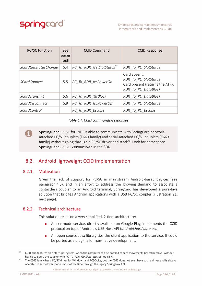
Smartcards and contactless smartcardsIntegrators's and Implementer's Guide
PC/SC function Seeparagraph
CCID Command CCID Response
SCardGetStatusChange 5.4 PC_To_RDR_GetSlotStatus39 RDR_To_PC_SlotStatus
SCardConnect 5.5 PC_To_RDR_IccPowerOn
Card absent:RDR_To_PC_SlotStatusCard present (returns the ATR):RDR_To_PC_DataBlock
SCardTransmit 5.6 PC_To_RDR_XfrBlock RDR_To_PC_DataBlock
SCardDisconnect 5.9 PC_To_RDR_IccPowerOff RDR_To_PC_SlotStatus
SCardControl PC_To_RDR_Escape RDR_To_PC_Escape
Table 14: CCID commands/responses
SpringCard.PCSC for .NET is able to communicate with SpringCard network-attached PC/SC couplers (E663 family) and serial-attached PC/SC couplers (K663 family) without going through a PC/SC driver and stack40. Look for namespace SpringCard.PCSC.ZeroDriver in the SDK.
8.2. Android lightweight CCID implementation
8.2.1. Motivation
Given the lack of support for PC/SC in mainstream Android-based devices (seeparagraph 4.6), and in an effort to address the growing demand to associate acontactless coupler to an Android terminal, SpringCard has developed a pure-Javasolution that bridges Android applications with a USB PC/SC coupler (illustration 21,next page).
8.2.2. Technical architecture
This solution relies on a very simplified, 2-tiers architecture:
A user-mode service, directly available on Google Play, implements the CCIDprotocol on top of Android’s USB Host API (android.hardware.usb),
An open-source Java library ties the client application to the service. It couldbe ported as a plug-ins for non-native development.
39 CCID also features an “interrupt” system, when the computer can be notified of card movements (insert/remove) without having to query the coupler with PC_To_RDR_GetSlotStatus periodically.
40 The E663 family has a PC/SC driver for Windows and PCSC-Lite, but the K663 does not even have such a driver and is always operated in zero-driver mode, most of the time through the legacy SpringProx API.
All information in this document is subject to the disclaimers stated on last page.
PMD17041 - AA Page 124 / 128
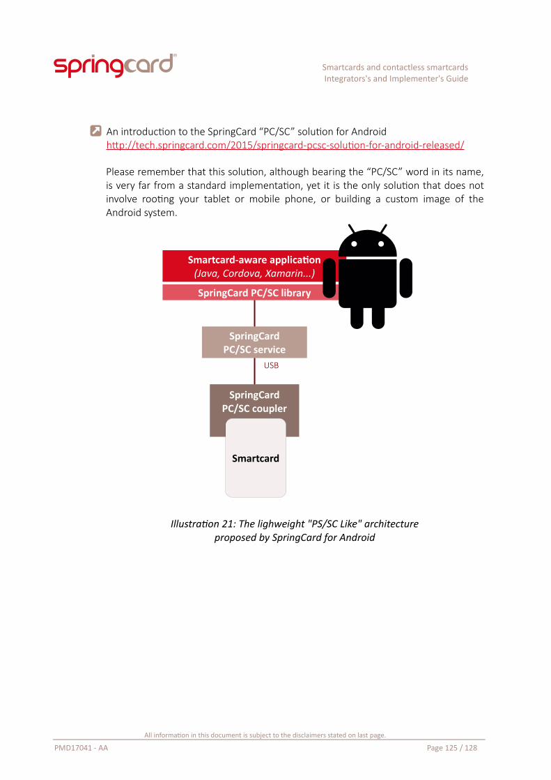
Smartcards and contactless smartcardsIntegrators's and Implementer's Guide
An introduction to the SpringCard “PC/SC” solution for Androidhttp://tech.springcard.com/2015/springcard-pcsc-solution-for-android-released/
Please remember that this solution, although bearing the “PC/SC” word in its name,is very far from a standard implementation, yet it is the only solution that does notinvolve rooting your tablet or mobile phone, or building a custom image of theAndroid system.
Illustration 21: The lighweight "PS/SC Like" architectureproposed by SpringCard for Android
All information in this document is subject to the disclaimers stated on last page.
PMD17041 - AA Page 125 / 128
Smartcard-aware application(Java, Cordova, Xamarin...)
SpringCardPC/SC service
SpringCardPC/SC coupler
USB
Smartcard
SpringCard PC/SC library
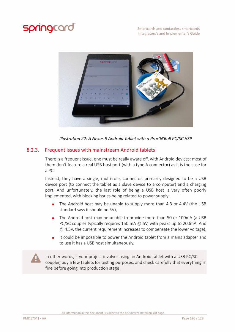
Smartcards and contactless smartcardsIntegrators's and Implementer's Guide
Illustration 22: A Nexus 9 Android Tablet with a Prox'N'Roll PC/SC HSP
8.2.3. Frequent issues with mainstream Android tablets
There is a frequent issue, one must be really aware off, with Android devices: most ofthem don’t feature a real USB host port (with a type A connector) as it is the case fora PC.
Instead, they have a single, multi-role, connector, primarily designed to be a USBdevice port (to connect the tablet as a slave device to a computer) and a chargingport. And unfortunately, the last role of being a USB host is very often poorlyimplemented, with blocking issues being related to power supply:
The Android host may be unable to supply more than 4.3 or 4.4V (the USBstandard says it should be 5V),
The Android host may be unable to provide more than 50 or 100mA (a USBPC/SC coupler typically requires 150 mA @ 5V, with peaks up to 200mA. And@ 4.5V, the current requirement increases to compensate the lower voltage),
It could be impossible to power the Android tablet from a mains adapter andto use it has a USB host simultaneously.
In other words, if your project involves using an Android tablet with a USB PC/SC coupler, buy a few tablets for testing purposes, and check carefully that everything isfine before going into production stage!
All information in this document is subject to the disclaimers stated on last page.
PMD17041 - AA Page 126 / 128
Smartcards and contactless smartcardsIntegrators's and Implementer's Guide
“Terminating a development-related book after exactly 27 pages is a kind of fullness!”
All information in this document is subject to the disclaimers stated on last page.
PMD17041 - AA Page 127 / 128
Smartcards and contactless smartcardsIntegrators's and Implementer's Guide
LEGAL INFORMATION
DisclaimerInformation in this document is subject to change withoutnotice.
This document is provided for informational purposes onlyand shall not be construed as a commercial offer, a license,an advisory, fiduciary or professional relationship betweenSPRINGCARD and you. No information provided in thisdocument shall be considered a substitute for yourindependent investigation.
The information provided in document may be related toproducts or services that are not available in your country.
This document is provided "as is" and without warranty ofany kind to the extent allowed by the applicable law. WhileSPRINGCARD will use reasonable efforts to provide reliableinformation, we don't warrant that this document is free ofinaccuracies, errors and/or omissions, or that its content isappropriate for your particular use or up to date.SPRINGCARD reserves the right to change the information atany time without notice.
SPRINGCARD doesn't warrant any results derived from theuse of the products described in this document. SPRINGCARDwill not be liable for any indirect, consequential or incidentaldamages, including but not limited to lost profits orrevenues, business interruption, loss of data arising out of orin connection with the use, inability to use or reliance on anyproduct (either hardware or software) described in thisdocument.
These products are not designed for use in life supportappliances, devices, or systems where malfunction of theseproduct may result in personal injury. SPRINGCARDcustomers using or selling these products for use in suchapplications do so on their own risk and agree to fullyindemnify SPRINGCARD for any damages resulting from suchimproper use or sale.
Copyright informationSPRINGCARD, the SPRINGCARD logo are registeredtrademarks of SPRINGCARD SAS.
MIFARE, MIFARE Classic, MIFARE Plus, MIFARE UltraLight, MIFARE Desfire, the MIFARE and the NXP logos are registeredtrademarks of NXP B.V.
NFC Forum is a trademark or registered trademark of NFC Forum, Inc. in the U.S. and in other countries.
Linux is the registered trademark of Linus Torvalds in the U.S. and other countries.
UNIX is a registered trademark of the Open Group.
Apple, the Apple logo and macOS are registered trademarks of Apple, Inc. in the U.S. and in other countries.
Windows and the Windows logo are registered trademarks ofMicrosoft Corporation in the U.S. and in other countries.
All other brand names, product names, or trademarks belongto their respective holders.
Copyright noticeAll information in this document is either public informationor is the intellectual property of SPRINGCARD and/or itssuppliers or partners.
You are free to view and print this document for your ownuse only. Those rights granted to you constitute a license andnot a transfer of title: you may not remove this copyrightnotice nor the proprietary notices contained in thisdocuments, and you are not allowed to publish or reproducethis document, either on the web or by any mean, withoutwritten permission of SPRINGCARD.
Copyright © SPRINGCARD SAS 2018, all rights reserved.
EditorSPRINGCARD SAS au capital de 227 000 €
RCS EVRY B 429 665 482
Parc Gutenberg, 13 voie La Cardon, 91120 Palaiseau
FRANCE
ContactFor more information and to locate our sales office ordistributor in your country or area, please visit:
www.springcard.com
All information in this document is subject to the disclaimers stated on last page.
PMD17041 - AA Page 128 / 128