Embed Size (px)
Citation preview
11th World Congress on Computational Mechanics (WCCM XI)5th European Conference on Computational Mechanics (ECCM V)
6th European Conference on Computational Fluid Dynamics (ECFD VI)E. Onate, J. Oliver and A. Huerta (Eds)
INTEGRATIVE SIMULATION FOR ASSESSING THEMECHANICAL PERFORMANCE OF A WELD LINE ON
INJECTION MOULDED THERMOPLASTIC PARTS
CAMILO A. CRUZ
Corporate Research, Advanced Production Technology 1 - Plastics TechnologyCR/APP2, Robert Bosch GmbH
Postfach 11 31, 71301 Waiblingen, Germanye-mail: [email protected]
Key words: Injection moulding, Thermoplastics, Weld line, Reptation theory
Abstract. Weld lines are commonly weak spots in thermoplastic injection-moulded parts.Predicting the healing degree of the polymer matrix at the weld line interface is neces-sary for enriching the material modelling at the weld line zone. A structural simulationbased on such enhanced material modelling would be more accurate and advantageousin terms of product design. In this regard, a physical modelling of the healing degreebetween polymer interfaces has been developed and used to refine a structural simula-tion intended to predict the maximal strength of a structure under quasi-static loading.The simulation has been compared to experimental tensile tests performed on specimensinjection-moulded with an unreinforced ABS matrix and a 30 wt% glass-fibre reinforcedPBT matrix. Strength prediction in the case of the unreinforced polymer has been foundsatisfactory, proving the capabilities of the model estimating the healing between polymerinterfaces. However, large deviations in the strength prediction for the reinforced matrixhave been found. Those divergences are probably due to the reduced accuracy of thepredicted fibre-orientation at the weld line zone.
1 INTRODUCTION
Injection moulding is one of the most widespread techniques for forming thermoplasticparts at industrial scale. Weld lines constitute one of the main concerns of such trans-forming process in terms of mechanical performance of the final part. In brief, weld linesare entities formed when two melt flow fronts collide inside a mould cavity. Multipleinjection points or complex geometries where flow is split in several melt fronts are causesfor the formation of weld lines and are, practically, unavoidable in the framework of thecurrent design of engineering plastic parts [1, 2, 3].
Given the rapid cooling rates imposed during an injection moulding cycle, completehealing between the encountered melt fronts cannot be guaranteed. In addition, weld
1
Camilo A. Cruz
line formation is normally accompanied by a flow-induced molecular orientation of thepolymer chains parallel to the weld line interface that makes more difficult the chaininterpenetration [4]. According to Hagerman, weakness of weld lines in unreinforcedamorphous polymer parts can be attributed essentially to three factors: 1) incompletebonding at the weld line interface, 2) the preferential molecular orientation at the interfacecaused by the fountain flow and 3) the apparition of V-notches around the weld-linebecause of air entrapment, for example [5]. Using local flow simulation, Nguyen concludedthat one of the main sources of weld line weakness is the V-notch, as result of, on the onehand, the poor bonding between polymer interfaces in the zones close to the mould and,on the other hand, the molecular orientation parallel to the weld line that enhances theshrinkage near to the wall [6].
In the case of semi-crystalline polymers, the morphological crystalline distributionalong the weld line interface is supposed also to play a decisive role on the weld linestrength. In addition, special crystallisation phenomena induced by the particular flowphenomena at the weld line should be taken into consideration. On another note, wheninjection moulding fibre-reinforced thermoplastics, the flow phenomena during the weldline formation usually induce a microstructure where fibres appear preferentially orientedparallel to the weld line interface. Such microstructures, as flower and volcano-like pat-terns, are clearly a disadvantage in terms of mechanical performance at the location of theweld line [7]. In consequence, mechanical properties at the weld line interface are mainlydependent on the healing quality and the molecular orientation state at the polymer-polymer interface.
The impact of weld lines on the mechanical performance of injected plastic parts hasbeen extensively studied in literature. Tensile strength, fracture energy and fracturetoughness of injected parts with unreinforced polymers are all substantially reduced inpresence of a weld line [8]. In addition, the reduction of the aforementioned mechanicalproperties is more drastic when dealing with short-glass-fibre reinforced specimens [9, 10,11].
There are two main types of weld lines: stagnating ones and flowing ones. In the firstcase, once the melt flows are encountered the velocity field at the melt front drops sharplyand the weld line interface appears static in the reference system of the mould cavity. Onthe other hand, we deal with a flowing weld line when a weld line interface is formedbut the local flow is not blocked. Then, weld line interface moves inside the cavity untilstagnation of the melt flow is reached. Flowing weld line is the most common kind ofweld lines founded in industrial applications.
Currently, most of the software simulating the injection moulding process offer the pos-sibility of predicting the formation, the displacement and the final location of weld lines,but the quality of the welding is frequently given only in a qualitative scale. Neverthe-less, several attempts for modelling quantitatively the healing of a weld line interface canbe found in literature. The free-energy-driven inter-diffusion of polymer chains and theinduced molecular orientation at the weld line interface have been usually modelled inde-
2
Camilo A. Cruz
pendently in order to predict the weld line strength [4, 12]. In addition to the classicaldiffusion models, polymer reptation can be also mentioned among the approaches em-ployed for describing the bridging of polymer interfaces at the weld line [13, 14]. Healingprocess between two polymer interfaces is basically a temperature-driven phenomenon;hence modelling of the healing is strongly dependent on the thermal history at the weldline interface. Some other modelling approaches are more focused on the flow behaviour atthe advancing front in order to take into account the molecular orientation factor [15, 16].
The aim of this work was, on the one hand, to implement a physical model describ-ing the local healing between polymer interfaces, using as input parameters the thermo-mechanical history of a weld line interface obtained from an injection-moulding simulationcarried out with commercial software. On the other hand, the objective was to establishan integrative simulation chain -from process to structural simulation- in order to pre-dict, for example, the maximal strength of an injected thermoplastic part containing weldlines when submitted to a quasi-static loading. Validation of the simulation approach wasmade in front of the results of experimental tensile tests.
2 MATERIALS AND METHODS
Two commercial engineering polymers were employed in the study: an unreinforcedacrylonitrile-butadiene-styrene copolymer (ABS) and a 30 wt% glass-fibre reinforced poly-butylene terephthalate (PBT-GF30). Tensile bar specimens with different thicknesses(1.5 mm and 3.0 mm) were injection moulded using one or two in-gates at the extremesof the specimens. In the first case, a specimen without weld line was obtained. In theother case, a specimen with a frontal weld line (stagnating weld line) in the middle ofthe bar was produced. Different processing parameters (mould and melt temperature)were used to induce different healing qualities at the weld line interface. In the case ofthe amorphous polymer, the mould temperature was varied between 40 ◦C and 80 ◦C,whereas the melt temperature at nozzle was set between 250 ◦C and 280 ◦C. For the rein-forced semi-crystalline polymer, the mould temperature was varied from 60 ◦C to 100 ◦C,whereas the melt temperature at nozzle was fixed at 265 ◦C. Tensile tests at 1 mm/min(with a 10 mm extensometer placed on the middle of the bar) were performed on theinjection moulded specimens in order to characterize the tensile mechanical properties ofthe materials with and without frontal weld lines. Injection moulding and tensile testingwere carried out at the PIMM laboratory (Arts et Metiers ParisTech, Paris, France).
3 SIMULATION TECHNIQUE
3.1 Modelling of the matrix healing at the weld line
In order to model the inter-diffusion of polymer chains at the interface of a weld linewe employ the reptation theory, which describes the dynamics of a linear polymer chain(entangled regime) in the melt state. This theory was first stated by De Gennes [17]and, afterwards, enriched by Doi and Edwards [18, 19]. According to the theory, a single
3
Camilo A. Cruz
polymer molecule in the melt state that is entangled in the middle of other polymer chainscan be modelled as a chain embedded inside a tube. The form and the dimensions of thattube would reflect the density of entanglements in the polymer melt. The diffusion of thepolymer chain can only occur along the tube, moving forward and backwards. Therefore,the macromolecule is allowed to adopt other configurations only at the extremes of thetube. The time that a given polymer chain requires to escape totally from a tube andadopt a totally new configuration is defined as the reptation time. Reptation time canalso be interpreted as the time required by a polymer chain to self-diffuse a distance equalto one radius of gyration.
One of the strengths of the reptation theory is the identification of a clear relationshipbetween the phenomena at the microscopic scale (polymer chain diffusion) and the thermo-mechanical behaviour at the macroscopic scale (rheological properties of the polymermelt). According to the theory, the reptation time or the characteristic time requiredby a polymer chain for reaching a new topological configuration can be estimated fromthe spectra of terminal relaxation times identified by rheological characterization of thepolymer melt. The crux of the matter lies on the methodology for quantifying suchcharacteristic times based on experimental rheological data. More detailed informationabout the different approaches for identifying the reptation time from rheological datacan be found elsewhere [13, 14].
In this work, reptation time is supposed to be associated with the shear rate at whichthe melt starts exhibiting rheo-thinning behaviour. In practice, the aforementioned char-acteristic time can be calculated using the classical models describing the shear-thinningbehaviour of a Cross-fluid in function of the shear rate (Cross model). Reptation time istherefore estimated as the longest relaxation time of an ideal Cross fluid, as given in thenext equation:
tR ≈η0τ ∗
(1)
where tR is the reptation time, τ ∗ is a critical shear stress (characteristic for eachpolymer) and η0 is the Newtonian shear viscosity. The Newtonian shear viscosity ofthe polymer melt can be also modelled in function of the temperature and the pressurefollowing a WLF model or an Arrhenius model. In consequence, the reptation timeestimated with equation (1) is, at the same time, dependent on temperature and pressure.
The previous quantitative estimation of the reptation time is clearly a simplificationapproach because, on the one hand, it is constrained by the mathematical structure ofthe Cross-fluid model and, on the other hand, it averages the actual spectra of relaxationtimes found in a commercial polymer matrix, where the molecular weight distribution isgenerally not mono-disperse.
By supposing that the polymer chain diffusion at the weld line interface is drivenby reptation, it can be stated that the weld line interface disappears (i.e. the polymerconfiguration distribution at the weld line is indistinguishable from that one at the bulkmelt) when the polymer chains are allowed to diffuse during one reptation time. In
4
Camilo A. Cruz
consequence, by over passing this critical diffusion time the mechanical behaviour of thematerial at the weld line interface would be the same as that one in the bulk. In thatcontext, the local healing degree at the weld line interface can be then quantified as theratio between the physical and the reptation time, integrated for a given local thermo-mechanical history at the weld line interface. Mathematically, the local healing degree ofthe polymer matrix would read as follows:
Q =
∫ tf
t0
dt
tR(T, P )(2)
where Q is the local healing degree (that can goes from 0 until ∞), t0 is the timewhen the first local contact between melt fronts is established during the weld line for-mation and tf corresponds to the time when the local temperature falls down to a levelin which reptation can be neglected. Reptation is strongly hindered below glass transi-tion temperature for an amorphous matrix and below crystallisation temperature for asemi-crystalline polymer.
In the framework of the present modelling approach, the thermo-mechanical history atthe weld line interface was obtained using commercial software simulating the injectionmoulding process. In this case, the required analysis sequence for the injection-mouldingsimulation was the following: filling, packing, in-mould cooling and out-of-mould cooling.For the sake of simplicity, t0 in equation (2) was fixed at the time of end of filling,independently of the position of the weld line. Previous hypothesis is supported by thefact that the time for filling the cavity is very short in comparison with the time requiredto cool down the part below the glass transition or the crystallisation temperature. Inthis modelling approach, the spatial resolution of the local healing degree at the weld linedepends on the mesh density employed in the injection moulding simulation.
3.2 Finite-Elements structural simulation
In this study, the structural simulation was intended to mimic the experimental tensiletesting carried out on the injection-moulded specimens with and without weld line. TheAbaqusr/Implicit code was selected in this work to perform the simulations of the tensiletests. The tensile test was simulated in the framework of a quasi-static loading, i.e.the rate of loading was not considered in the simulation. Fundamentally, we appliedto two different simulation techniques depending on the existence or not of glass-fibrereinforcement. In addition, for each kind of material, two different structural simulationswere performed: tensile test on a specimen without weld line (reference case) and tensiletest on a specimen with weld line.
3.2.1 Unreinforced ABS material
The mechanical response of the amorphous polymer matrix was simulated using anisotropic elasto-plastic model with isotropic hardening. The yield stress was identified
5
Camilo A. Cruz
from the true tensile stress - logarithmic strain curve at the off-set yield strength at 0.05 %of deformation (as approximation of the onset of the non-linear stress-strain behaviour).Using this criterion, yield stress for the ABS material was set equal to 26 MPa.
In order to consider the weld line on the structural simulation, the local healing degreeQ of the elements (process-simulation mesh) belonging to the weld line was calculatedusing the equation (2). The required local thermo-mechanical history at the weld linewas obtained from a process simulation performed in Moldflowr. As result, each elementmarked as weld line was characterized by a local healing degree that quantifies the qualityof the polymer inter-diffusion. Theoretically, a welding interface of an amorphous polymerwith a mono-disperse molecular-weight distribution should completely heal by diffusingduring one-reptation time. In other words, the matrix with a local healing degree equalor greater than one (Q ≥ 1) would be indistinguishable from the bulk matrix and shouldexhibit the same mechanical behaviour. On the other hand, the matrix with a local healingdegree lower than one (Q < 1) would have not reached the same density of entanglementsas the bulk matrix and would exhibit a brittle behaviour. Nevertheless, we deal herewith a poly-disperse molecular-weight distributed matrix and, therefore, the Q-thresholdrepresenting the complete healing of the polymer matrix could be different from one. Inthis work, we have employed a security factor SF for taking into account this deviation.The mechanical behaviour of the polymer matrix with a local healing degree equal orgreater than the security factor (Q ≥ SF ) would be then the same of the bulk material.On the other hand, the elements with a local healing degree lower than the security factor(Q < SF ) were mapped from the process-simulation mesh to the structural simulation-mesh and sub-modelled using an ideal elasto-plastic material law. Previous material lawis clearly a simplification hypothesis. In this case, the behaviour at rupture was not takeninto account and the simulation should be evaluated only in the framework of a strength-criterion design; in other words, the simulation is supposed to give an estimation of themaximal stress that the structure can load. The Young’s modulus was assumed not to beaffected by the presence of the weld line and the yielding stress was fixed at 26 MPa (asin the bulk material).
3.2.2 Reinforced PBT material
The mechanical behaviour of the semi-crystalline matrix was described using an iso-tropic elasto-plastic material law with isotropic hardening. The corresponding modelparameters were identified by reverse engineering on tensile curves measured on bars cutfrom injection-moulded 2 mm plaques. The reverse engineering process in Digimatr wasperformed using the tensile data obtained from bars cut in the longitudinal, transversaland 30◦ (with respect to the injection) directions and the experimental 3D fibre-orientationmeasured on the plaque with computed tomography.
The tensile test of the specimens without weld line were simulated then using Abaqusr
coupled with DigimatrCAE in order to take into account the anisotropy induced by the
6
Camilo A. Cruz
fibre orientation. Prediction of the fibre-orientation was obtained in Moldflowr usingthe in-built Folgar-Tucker orientation model with auto-calculated interaction coefficient.Simulated fibre orientation was mapped from the process-simulation to the structural-simulation mesh using DigimatrMAP.
Simulated tensile tests on the specimens containing a weld line were also performedusing Abaqusr coupled with DigimatrCAE. Nevertheless, additional information wasrequired in order to take into account the presence of the weld line. In this case, themechanical behaviour at the weld line was simulated by considering two independenteffects: healing degree of the polymer matrix and the particular fibre orientation in thesurroundings of the weld line. The mechanical behaviour of the bulk polymer matrixwas represented by the identified isotropic elasto-plastic model with isotropic hardening.In analogy with the simulation of the unreinforced material, the weld line elements witha local healing degree lower than the security factor (Q < SF ) were mapped from theprocess-simulation to the structural-simulation mesh and sub-modelled with a penalizedmatrix material model (ideal elasto-plastic material law with yielding stress at 23.5 MPa).On the other hand, the fibre orientation was also obtained from the Moldflowr simulation(Folgar-Tucker model with auto-calculated interaction coefficient) and transferred, in astandard way, to the structural simulation mesh employing DigimatrMAP.
4 RESULTS AND DISCUSSION
4.1 Unreinforced ABS material
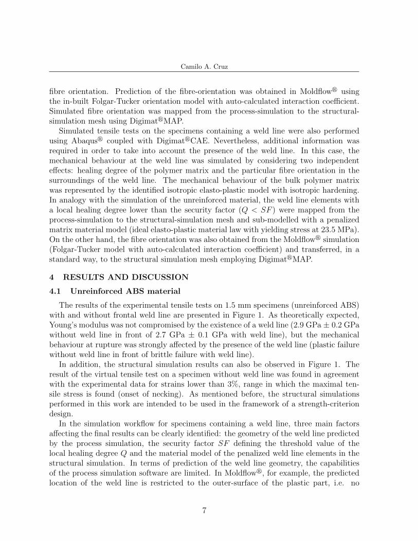
The results of the experimental tensile tests on 1.5 mm specimens (unreinforced ABS)with and without frontal weld line are presented in Figure 1. As theoretically expected,Young’s modulus was not compromised by the existence of a weld line (2.9 GPa ± 0.2 GPawithout weld line in front of 2.7 GPa ± 0.1 GPa with weld line), but the mechanicalbehaviour at rupture was strongly affected by the presence of the weld line (plastic failurewithout weld line in front of brittle failure with weld line).
In addition, the structural simulation results can also be observed in Figure 1. Theresult of the virtual tensile test on a specimen without weld line was found in agreementwith the experimental data for strains lower than 3%, range in which the maximal ten-sile stress is found (onset of necking). As mentioned before, the structural simulationsperformed in this work are intended to be used in the framework of a strength-criteriondesign.
In the simulation workflow for specimens containing a weld line, three main factorsaffecting the final results can be clearly identified: the geometry of the weld line predictedby the process simulation, the security factor SF defining the threshold value of thelocal healing degree Q and the material model of the penalized weld line elements in thestructural simulation. In terms of prediction of the weld line geometry, the capabilitiesof the process simulation software are limited. In Moldflowr, for example, the predictedlocation of the weld line is restricted to the outer-surface of the plastic part, i.e. no
7
Camilo A. Cruz
Figure 1: Experimental and simulation results of a tensile test on a 1.5 mm specimen injected with anamorphous polymer (with and without frontal weld line)
information about the weld line position through the thickness is given. As the positionand form of the weld line could be easily predicted in this study, the weld line wassupposed to be formed at the mid-plane of the tensile bar and the local healing degree Qwas calculated for all the elements cut by such cross section.
The material model for the penalized weld line elements is obviously a factor playing arole on the structural simulation results. Here, nevertheless, the matrix material model forthe penalized matrix elements was defined in a physical basis in order to keep it constantand reduce the degrees of freedom of the simulation. By defining the maximal stress ofthe penalized elements (yield stress in the elasto-plastic material law without hardening)at the same stress-level from which a true stress - log strain tensile curve starts exhibitinga non-linear behaviour, we intended to mimic the maximal strength of a poorly healedweld line interface. In fact, we assumed that the maximal strength of a poorly healedweld line interface (i.e. polymer matrix with a lower density of entanglements than theone in the bulk matrix) cannot be greater than the critical stress which triggers thelocalized plasticity phenomena in the bulk matrix. In front of the previous statement,we additionally supposed that the onset of the macroscopic non-linearity in the truestress - log strain tensile curve is associated with the development of localized plasticityphenomena (microscopic shear plastic bands, for example).
In such framework, the factors influencing the structural simulation of specimens con-taining a weld line were simply reduced to the security factor SF . As mentioned before,
8
Camilo A. Cruz
the security factor SF is intended to correct the deviation between the estimated meanreptation time and the spectrum of reptation times that is particular to a polymer witha multi-disperse molecular-weight distribution. For that reason, the simulation results ofthe tensile test on specimens with weld line in Figure 1 are given for three different valuesof security factor SF . It was found that the actual maximal strength of the specimenwith weld line (39.7 MPa ± 0.9 MPa) can be predicted by using a security factor SFbetween 1 and 2, where SF = 1 gives the most accurate prediction (40.6 MPa). Thisresult means either that the mean reptation time estimated with equation (1) describescorrectly the global polymer dynamics of the ABS (with a given spectrum of reptationtimes) or that the poly-dispersity of the amorphous polymer is close to one.
4.2 Reinforced PBT material
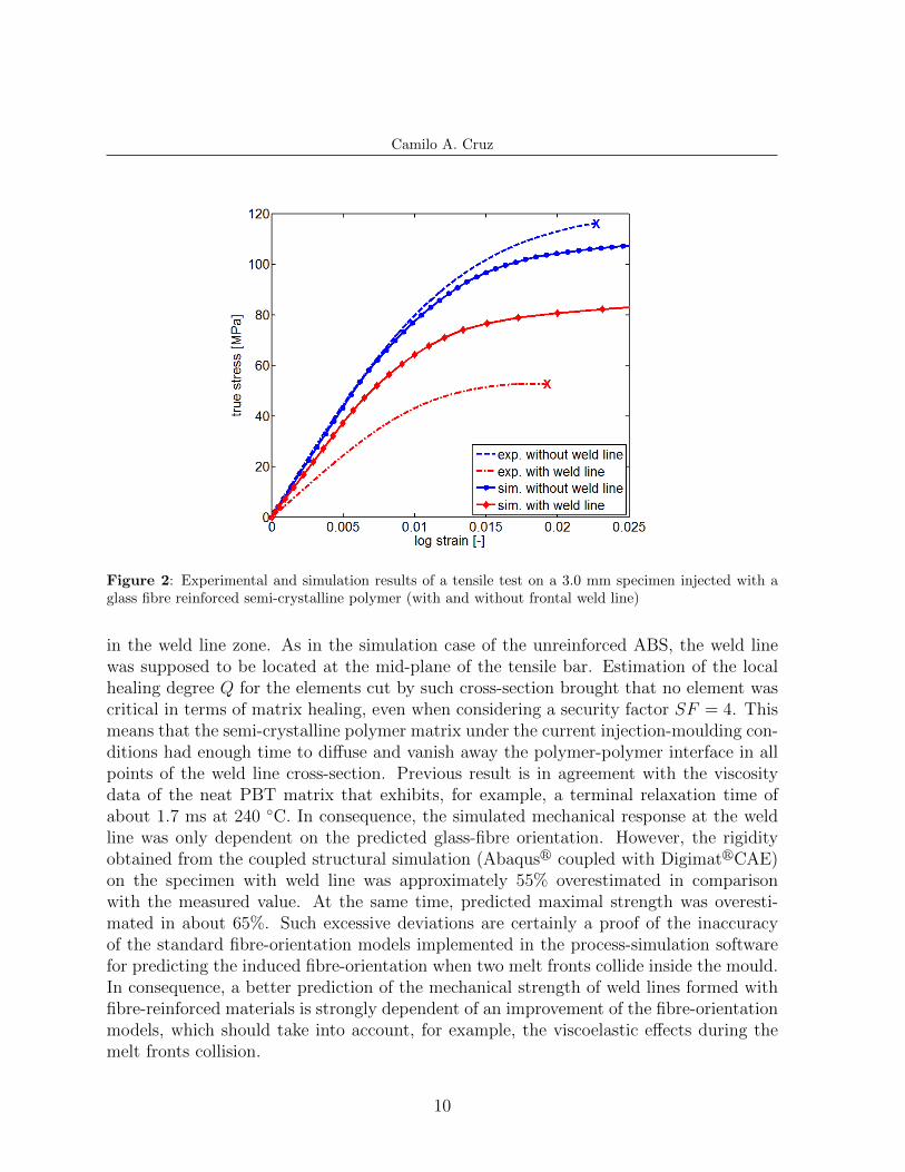
The experimental tensile tests on 3.0 mm specimens (PBT-GF30) with and withoutfrontal weld line are presented in Figure 2. Reinforced specimens exhibited a brittlebehaviour independent of the presence or not of a weld line. Nevertheless, the frontalweld line had a dramatic effect on the Young’s modulus and the maximal strength of thespecimen. In terms of rigidity, Young’s modulus was reduced in 46% by the presence of theweld line, falling down from 9.1 GPa ± 0.1 GPa to 4.9 GPa ± 0.1 GPa. Given the fact thatthe elastic response of the matrix at the weld line interface should not be substantiallycompromised (a slight change of matrix rigidity could occur by a modification of thecrystalline content and microstructure); the radical diminution in Young’s modulus shouldbe related to a severe change in glass fibre orientation in the zone of the weld line. On theother hand, maximal strength was decreased in approximately 55% from 113.6 MPa ±1.5 MPa without weld line to 50.6 MPa ± 1.0 MPa with weld line. To infer the possiblecauses of such decrease in strength is more delicate because of the multiple phenomenainvolved in failure, but certainly such reduction in strength was mainly induced by thediminution in rigidity.
The result of the coupled structural simulation (Abaqusr coupled with DigimatrCAE)on the specimen without weld line is also shown in Figure 2. Here, the linear elasticresponse was correctly described, i.e. for strains lower than 0.7%. This fact probablyindicates that the fibre orientation predicted by Moldflowr was in agreement with thereality, at least in terms of averaged orientation in the cross-section of the specimen.Simulated non-linear stress-strain response was, however, slightly underestimated. Inthe range of strains lower than 3% (classical limit-deformation for this kind of reinforcedcompounds), the simulated strength was approximately 5% smaller than the experimentalmaximal strength. We should recall that the structural simulations in this study areintended to be used in the framework of strength-criterion design. Failure behaviour isnot simulated here.
In the case of the specimen containing a frontal weld line, the mechanical responseat the weld line was simulated by considering two independent effects: on the one hand,healing degree of the polymer matrix and, on the other hand, the induced fibre orientation
9
Camilo A. Cruz
Figure 2: Experimental and simulation results of a tensile test on a 3.0 mm specimen injected with aglass fibre reinforced semi-crystalline polymer (with and without frontal weld line)
in the weld line zone. As in the simulation case of the unreinforced ABS, the weld linewas supposed to be located at the mid-plane of the tensile bar. Estimation of the localhealing degree Q for the elements cut by such cross-section brought that no element wascritical in terms of matrix healing, even when considering a security factor SF = 4. Thismeans that the semi-crystalline polymer matrix under the current injection-moulding con-ditions had enough time to diffuse and vanish away the polymer-polymer interface in allpoints of the weld line cross-section. Previous result is in agreement with the viscositydata of the neat PBT matrix that exhibits, for example, a terminal relaxation time ofabout 1.7 ms at 240 ◦C. In consequence, the simulated mechanical response at the weldline was only dependent on the predicted glass-fibre orientation. However, the rigidityobtained from the coupled structural simulation (Abaqusr coupled with DigimatrCAE)on the specimen with weld line was approximately 55% overestimated in comparisonwith the measured value. At the same time, predicted maximal strength was overesti-mated in about 65%. Such excessive deviations are certainly a proof of the inaccuracyof the standard fibre-orientation models implemented in the process-simulation softwarefor predicting the induced fibre-orientation when two melt fronts collide inside the mould.In consequence, a better prediction of the mechanical strength of weld lines formed withfibre-reinforced materials is strongly dependent of an improvement of the fibre-orientationmodels, which should take into account, for example, the viscoelastic effects during themelt fronts collision.
10
Camilo A. Cruz
5 CONCLUSIONS
Quality of the polymer healing at the weld line interface has been modelled based onthe reptation theory, which describes the inter-diffusion of macromolecules. An estimationof the local healing degree can be calculated then from the thermo-mechanical history ofthe polymer matrix in a given point of the weld line. The strength contribution of thepolymer matrix in the macroscopic mechanical response of a weld line has been simulatedby defining that the maximal strength of a poorly healed polymer interface is equal to thecritical stress triggering the localized plastic phenomena in the bulk matrix (estimated asthe onset of the non-linear behaviour of a macroscopic true stress - log strain tensile curve).In the case of the unreinforced ABS, the threshold of local healing degree which establishesthe passage from a poorly healed to a completely healed interface (bulk polymer matrix)has been found close to 1 (theoretical value according to the reptation theory). For areinforced matrix, the mechanical response of a weld line not only depends on the polymermatrix, but also on the fibre orientation. In the particular case of the 30 wt% glass-fibrereinforced PBT matrix, strength contribution of the semi-crystalline polymer has beenfound no compromised by an eventual incomplete healing at the weld line interface, i.e.polymer matrix has been modelled as bulk material even at the weld line interface. Inconsequence, the simulated mechanical response of the weld line was exclusively dependenton the predicted fibre-orientation. The excessive deviation found between the measuredand simulated strength of the weld line would reveal an inaccurate prediction of the fibre-orientation in the vicinity of the weld line. Such inaccuracy could be explained by the factthat the standard fibre-orientation models do not consider the additional flow phenomenaoccurring during the collision of melts fronts (e.g. viscoelastic contribution).
REFERENCES
[1] Wool, R.P. Polymer Interfaces - Structure and Strength. Hanser Publishers, Munich(1995).
[2] Malguarnera, S.C. and Manisali, A. The effects of processing parameters on thetensile properties of weld lines in injection molded thermoplastics. Polym. Eng. Sci.(1981) 21(10):586–593.
[3] Tadmore, Z. and Gogos, C.G. (editors). Principles of polymer processing. John Wiley(1979).
[4] Kim, S. and Suh, N.P. Performance prediction of weldline structure in amorphouspolymers. Polym. Eng. Sci. (1986) 26(17):1200-1207.
[5] Hagerman, E. Weld-line fracture in plastic parts. Plast. Eng. (1973) 29(10):67-69.
[6] Nguyen-Chung, T. Flow analysis of the weld line formation during injection moldfilling of thermoplastics. Rheo. Acta (2004) 43(3):240-245.
11
Camilo A. Cruz
[7] Lim, J. and Shoji, T. Fiber orientation of polymer injection weld and its strengthevaluation. KSME J. (1993) 7(2):173-181.
[8] Chrysostomou, A. and Hashemi, S. Mechanical properties of injection-mouldedstyrene maleic anhydride (SMA). Part I: Influence of weldline and reprocessing. J.Mater. Sci. (1998) 33(5):1165-1175.
[9] Chrysostomou, A. and Hashemi, S. Mechanical properties of injection mouldedstyrene maleic anhydride (SMA). Part II: Influence of short glass fibres and weldlines.J. Mater. Sci. (1998) 33(18):4491-4501.
[10] Nabi, Z.U. and Hashemi, S. Influence of short glass fibres and weldlines on the me-chanical properties of injection-moulded acrylonitrile-styrene-acrylate copolymer. J.Mater. Sci. (1998) 33(12):2985-3000.
[11] Hashemi, S. and Lepessova, Y. Temperature and weldline effects on tensile propertiesof injection moulded short glass fibre PC/ABS polymer composite. J. Mater. Sci.(2007) 42(8):2652-2661.
[12] Enikeev, A., Kazankov, Y. and Mironov, V. Mechanism of weld line formation ininjection molding of plastics. Chem. Pet. Eng. (1999) 35(1-2):118-123.
[13] Nicodeau, C. Modelisation du soudage en continu des composites a matrice thermo-plastique. PhD thesis, ENSAM, Paris (2005).
[14] Juhl, T.B., Christiansen, J.d.C. and Jensen, E.A. Investigation on high strength laserwelds of polypropylene and high-density polyethylene. J. Appl. Polym. Sci. (2013)129(5):2679-2685.
[15] Wei, K., Nordberg, M. and Winter, H. Simulation of planar welding flows 2. Strainhistory, stress calculation and experimental comparison. Polym. Eng. Sci. (1987)27(18):1390-1398.
[16] Mavridis, H., Hrymak, A. and Vlachopoulos, J. Transient free-surface flows in injec-tion mold filling. AIChE J. (1988) 34(3):403-410.
[17] De Gennes, P. G. Reptation of a polymer chain in the presence of fixed obstacles. J.Chem. Phys. (1971) 55(2):572-579.
[18] Doi, M. and Edwards, S. F. Dynamics of concentrated polymer systems. Part 1 -Brownian motion in the equilibrium state. J. Chem. Soc. Farad. T. 2 (1978) 74:1789-1801.
[19] Doi, M. and Edwards, S. F. Dynamics of concentrated polymer systems. Part 4 -Rheological properties. J. Chem. Soc. Farad. T. 2 (1979) 75:38-54.
12


![MULTIDISCIPLINARY ANALYSIS OF THE DLR SPACELINER …congress.cimne.com/iacm-eccomas2014/admin/files/fileabstract/a1… · [6] Kuntsevich A., Kappel F. SolvOpt manual: The solver for](https://img.pdfslide.us/doc/110x75/606ff92e1e3b98598339e4a5/multidisciplinary-analysis-of-the-dlr-spaceliner-6-kuntsevich-a-kappel-f-solvopt.jpg)

![NON-LINEAR ANALYSIS OF STEEL-CONCRETE BEAMS USING ...congress.cimne.com/iacm-eccomas2014/admin/files/filePaper/p3133.pdf · steel-concrete composite bridges [1] and (ii) elastoplastic](https://img.pdfslide.us/doc/110x75/5e738c9fa40ec15d9c253721/non-linear-analysis-of-steel-concrete-beams-using-steel-concrete-composite-bridges.jpg)