Embed Size (px)
Citation preview

Integration of Sketch-based Ideation
and 3D Modeling with CAD Systems
A thesis submitted in fulfillment of the requirement for
the degree of Doctorate of Philosophy
Islam Gharib
School of Engineering and Design
Brunel University

To my wife, Salma
Daughters, Zad and Lina

Acknowledgements
I am deeply indebted to my supervisors Dr. ShengFeng Qin and Dr. Jinsheng
Kang from Brunel University whose help, stimulating suggestions and
encouragement helped me all the time of research and writing of this thesis.
I would like to express my gratitude to Dr. Busayawan Lam for all her
comments and suggestions on this research. I have furthermore to thank Dr.
Feng Tian from Bournemouth University for his comments and suggestions for
improvement of this thesis.
Especially, I would like to give my special thanks to my family whose patient
love enabled me to complete this work.
This work is funded by four years scholarship from the Ministry of Higher
Education of Egypt.

Related publications
I. Gharib, and S. Qin. A Multi-Windows Approach for
Sketch-Based Conceptual Design System. Proceedings
of Theory and Practice of Computer Graphics,
Sheffield, pp. 231 -239, 6 – 8 September 2010.
I. Gharib, and S. Qin, Integration of sketch-based
conceptual design and commercial CAD systems for
manufacturing. International Journal of Advanced
Manufacturing Technology, March 2013.
Abstract
This thesis is concerned with the study of how sketch-based systems can be
improved to enhance idea generation process in conceptual design stage. It is
also concerned with achieving a kind of integration between sketch-based
systems and CAD systems to complete the digitization of the design process as
sketching phase is still not integrated with other phases due to the different
nature of it and the incomplete digitization of sketching phase itself. Previous
studies identified three main related issues: sketching process, sketch-based
modeling, and the integration between the digitized design phases. Here, the
thesis is motivated from the desire to improve sketch-based modeling to
support idea generation process but unlike previous studies that only focused
on the technical or drawing part of sketching, this thesis attempts to
concentrate more on the mental part of the sketching process which play a key
role in developing ideas in design. Another motivation of this thesis is to
produce a kind of integration between sketch-based systems and CAD systems
to enable 3D models produced by sketching to be edited in detailed design
stage. As such, there are two main contributions have been addressed in this
thesis. The first contribution is the presenting of a new approach in designing
sketch-based systems that enable more support for idea generation by
separating thinking and developing ideas from the 3D modeling process. This
kind of separation allows designers to think freely and concentrate more on
their ideas rather than 3D modeling. the second contribution is achieving a
kind of integration between gesture-based systems and CAD systems by using
an IGES file in exchanging data between systems and a new method to
organize data within the file in an order that make it more understood by
feature recognition embedded in commercial CAD systems.
i
Contents
1 Introduction 1
1.1 Overview . . . . . . . . . . . . . . . . . . . . . . . . . . 1
1.2 Conceptual Design and Sketching . . . . . . . . . . . . . . . 2
1.2.1 The Design Process . . . . . . . . . . . . . . . . . . . 2
1.2.2 Importance of Sketching . . . . . . . . . . . . . . . . . 4
1.2.2.1 Speed and Spontaneity . . . . . . . . . . . . . . 5
1.2.2.2 Flexibility and availability . . . . . . . . . . . . 5
1.2.2.3 Analysis . . . . . . . . . . . . . . . . . . . . 5
1.2.2.4 Creativity . . . . . . . . . . . . . . . . . . . 5
1.3 CAD and Conceptual Design . . . . . . . . . . . . . . . . . . 6
1.4 Sketch-based Modeling . . . . . . . . . . . . . . . . . . . . 7
1.4.1 Reconstruction-based Modeling . . . . . . . . . . . . . 7

CONTENTS
1.4.2 Gesture-based Modeling . . . . . . . . . . . . . . . . . 9
1.5 Problem Overview . . . . . . . . . . . . . . . . . . . . . . 11
1.5.1 Sketch-based Systems and Idea Generation Process . . . . . 12
1.5.2 Lack of Integration between sketch-based interfaces and CAD
Systems . . . . . . . . . . . . . . . . . . . . . . . . 13
1.6 Aims and Objectives . . . . . . . . . . . . . . . . . . . . . . 14
1.7 Methodology . . . . . . . . . . . . . . . . . . . . . . . . . 15
1.8 Contributions . . . . . . . . . . . . . . . . . . . . . . . . . 16
1.8.1 Multi-windows sketch-based interface to support idea generation
Process . . . . . . . . . . . . . . . . . . . . . . . . 16
1.8.2 Integration between sketch-based interfaces and commercial
CAD Systems . . . . . . . . . . . . . . . . . . . . 18
1.9 The Structure of this thesis . . . . . . . . . . . . . . . . . . . 19
2 Literature Review on Sketching Roles in Design and Sketch-based Interface
and Modeling System
20
2.1 Introduction . . . . . . . . . . . . . . . . . . . . . . . . . 20
2.2 Related Works . . . . . . . . . . . . . . . . . . . . . . . . 22
2.2.1 Sketching as a Mental Activity . . . . . . . . . . . . . . 22
2.2.2 Sketching as a Graphical Activity . . . . . . . . . . . . . . 24

CONTENTS
2.3 Analysis of Sketch’s Graphical Feature . . . . . . . . . . . . . . 25
2.3.1 Analysis Method . . . . . . . . . . . . . . . . . . . . 26
2.3.2 Results from Analysis . . . . . . . . . . . . . . . . . . 26
2.4 Questionnaire Study on Sketching Behavior and Designers’ Preferences
About Sketch-based Systems . . . . . . . . . . . . . . . . . . 29
2.4.1 The Design of Questionnaire . . . . . . . . . . . . . . . 30
2.4.2 Results of the Questionnaire Study . . . . . . . . . . . . 31
2.5 Sketching Scenario . . . . . . . . . . . . . . . . . . . . . . 35
2.6 System Structure . . . . . . . . . . . . . . . . . . . . . . . 37
2.6.1 2D Sketching . . . . . . . . . . . . . . . . . . . . . . 38
2.6.2 3D Modeling . . . . . . . . . . . . . . . . . . . . . . 40
2.6.3 Integration with Commercial CAD Systems . . . . . . . . . 41
2.7 Conclusion . . . . . . . . . . . . . . . . . . . . . . . . . . 42
3 Gesture Design and Recognition 44
3.1 Introduction . . . . . . . . . . . . . . . . . . . . . . . . . 44
3.2 Related Works . . . . . . . . . . . . . . . . . . . . . . . . 46
3.2.1 Gesture Design . . . . . . . . . . . . . . . . . . . . . 46
3.2.2 Beautification . . . . . . . . . . . . . . . . . . . . . 47

CONTENTS
3.2.3 Recognition process . . . . . . . . . . . . . . . . . . 48
3.3 Designing of Gestures . . . . . . . . . . . . . . . . . . . . . 49
3.3.1 3D Objects Analysis . . . . . . . . . . . . . . . . . . . 50
3.3.1.1 Sphere . . . . . . . . . . . . . . . . . . . . 50
3.3.1.2 Cylinder . . . . . . . . . . . . . . . . . . . . 51
3.3.1.3 Cone . . . . . . . . . . . . . . . . . . . . . 51
3.3.1.4 Frustum Cone . . . . . . . . . . . . . . . . . 51
3.3.1.5 Box . . . . . . . . . . . . . . . . . . . . . . 53
3.3.1.6 Pyramid . . . . . . . . . . . . . . . . . . . . 53
3.3.1.7 Extrusion . . . . . . . . . . . . . . . . . . . . 55
3.3.2 The Design of Gestures . . . . . . . . . . . . . . . . . . 56
3.3.3 Gesture Evaluation . . . . . . . . . . . . . . . . . . . 58
3.4 Gesture Recognition . . . . . . . . . . . . . . . . . . . . . . 62
3.4.1 Classification . . . . . . . . . . . . . . . . . . . . . . 62
3.4.1.1 Classification and Segmentation . . . . . . . . . 63
3.4.1.2 Circle Detection . . . . . . . . . . . . . . . . 64
3.4.3 Validation Test . . . . . . . . . . . . . . . . . . . . . 65
3.4.3.1 Stroke Number Recognition . . . . . . . . . . . 65
CONTENTS
3.4.3.2 Test Implementation . . . . . . . . . . . . . . 65
3.4.3.2.1 Sphere Test . . . . . . . . . . . . . 69
3.4.3.2.2 Cylinder and Cone Tests . . . . . . . . 69
3.4.3.2.3 Box and Frustum Cone Tests . . . . . 69
3.4.3.2.4 Extrusion and Pyramid Tests . . . . . . . 70
3.5 Positioning 3D Models . . . . . . . . . . . . . . . . . . . . . 70
3.5.1 Projection . . . . . . . . . . . . . . . . . . . . . . . 71
3.5.2 Reference Planes . . . . . . . . . . . . . . . . . . . . 72
3.6 Case studies . . . . . . . . . . . . . . . . . . . . . . . . . 73
3.6.1 Case Study 1 . . . . . . . . . . . . . . . . . . . . . . 74
3.6.2 Case Study 2 . . . . . . . . . . . . . . . . . . . . . . 76
3.6.3 Results from Case Studies . . . . . . . . . . . . . . . . 78
3.7 Conclusion . . . . . . . . . . . . . . . . . . . . . . . . . . 78
4 Integration between sketch-based interfaces and commercial CAD systems 81
4.1 Introduction . . . . . . . . . . . . . . . . . . . . . . . . . 81
4.2 Related Works . . . . . . . . . . . . . . . . . . . . . . . . 83
4.3 Integration Method . . . . . . . . . . . . . . . . . . . . . . 85
4.3.1 Extracting 3D information . . . . . . . . . . . . . . . . 87

CONTENTS
4.3.2 Producing an IGES file . . . . . . . . . . . . . . . . . . 88
4.3.2.1 Translation Process . . . . . . . . . . . . . . . 89
4.3.2.2 IGES Translator . . . . . . . . . . . . . . . . . 90
4.3.3 Importing IGES file into Commercial CAD Systems . . . . . . 91
4.4 Case Studies . . . . . . . . . . . . . . . . . . . . . . . . . 94
4.4.1 Case Study 1 . . . . . . . . . . . . . . . . . . . . . . 94
4.4.2 Case Study 2 . . . . . . . . . . . . . . . . . . . . . . 97
4.4.3 Case Study 3 . . . . . . . . . . . . . . . . . . . . . . 99
4.4.4 Results from Case Studies . . . . . . . . . . . . . . . . 101
4.5 Conclusion . . . . . . . . . . . . . . . . . . . . . . . . . . 102
5 User Study 104
5.1 Introduction . . . . . . . . . . . . . . . . . . . . . . . . . 104
5.2 User Study Description . . . . . . . . . . . . . . . . . . . . . 105
5.2.1 Tutorial Description . . . . . . . . . . . . . . . . . . . 105
5.2.1.1 Navigation Section . . . . . . . . . . . . . . . 106
5.2.1.2 Idea Generation Process . . . . . . . . . . . . . 107
5.2.1.3 3D Modeling Process . . . . . . . . . . . . . . 108
5.2.2 Questionnaire Description . . . . . . . . . . . . . . . . 109

CONTENTS
5.3 Implementation and Results . . . . . . . . . . . . . . . . . . 110
5.3.1 Implementation . . . . . . . . . . . . . . . . . . . . 110
5.3.2 Results . . . . . . . . . . . . . . . . . . . . . . . . . 111
5.3.2.1 Evaluation of Gestures . . . . . . . . . . . . . . 111
3.5.2.2 Evaluation of Idea Generation Process . . . . . . . 116
3.5.2.3 Evaluation of the 3D Modeling Process . . . . . . . 118
5.4 Conclusion . . . . . . . . . . . . . . . . . . . . . . . . . . 121
6 Discussion, Conclusion, and Future Work 124
6.1 Introduction . . . . . . . . . . . . . . . . . . . . . . . . . 124
6.2 Discussion . . . . . . . . . . . . . . . . . . . . . . . . . . 124
6.2.1 Enhancing Idea Generation Process . . . . . . . . . . . . 126
6.2.2 Integration with Commercial CAD Systems . . . . . . . . . 130
6.3 Conclusion and Future Works . . . . . . . . . . . . . . . . . . 132
A Sketches Analysis 135
B Sketching Questionnaire 138
C User Study’s Tutorial & Tasks 141
D User Study Questionnaire 156
References 159

vi
List of Figures
1.1 Phases of the product design process . . . . . . . . . . . . . . . . . 4
1.2 (a) over-traced sketch (b) non-traced sketch . . . . . . . . . . . . . 8
1.3 The lack of integration between sketch-based modeling and other design
stages . . . . . . . . . . . . . . . . . . . . . . . . . . . . . . 14
1.4 The work-flow of the system . . . . . . . . . . . . . . . . . . . . 17
1.5 The method used to achieve integration between sketch-based systems and
commercial CAD system . . . . . . . . . . . . . . . . . . . . . . 18
2.1 The sketching process parts . . . . . . . . . . . . . . . . . . . . . 22
2.2 some examples of sketches used in the analysis (Product design forum, 2010;
Eissen and Steur, 2007) . . . . . . . . . . . . . . . . . . . . . . . 27
2.3 The using of 2D and 3D drawing by design students and the professional
designers in sketches . . . . . . . . . . . . . . . . . . . . . . . 28
2.4 The using of shading, drop shading and coloring by design students and the
professional designers in sketches . . . . . . . . . . . . . . . . . . 28
2.5 The usage of assistant lines and annotation by design students and the

LIST OF FIGURES
professional designers in sketches . . . . . . . . . . . . . . . . . . 29
2.6 Mediums used by designers in sketching . . . . . . . . . . . . . . . 32
2.7 Ideation behavior of designers . . . . . . . . . . . . . . . . . . . 33
2.8 Graphical features used in sketches by designers . . . . . . . . . . . . 33
2.9 Using of 2D and 3D drawing in sketches . . . . . . . . . . . . . . . . 34
2.10 The assisting features that are used in sketches . . . . . . . . . . . . 34
2.11 Designers’ preferences about sketch-based systems . . . . . . . . . . 35
2.12 The sketching scenario . . . . . . . . . . . . . . . . . . . . . . . 36
2.13 The structure of the sketch-based system . . . . . . . . . . . . . . 39
2.14 The 2D sketching interface . . . . . . . . . . . . . . . . . . . . . 40
2.15 The 3D modeling interface . . . . . . . . . . . . . . . . . . . . . 41
3.1 The two ways of drawing sphere in 2D . . . . . . . . . . . . . . . . 50
3.2 Some different scenarios to draw cylinder in 2D . . . . . . . . . . . . 52
3.3 Some different scenarios to draw a cone in 2D . . . . . . . . . . . . 52
3.4 Some different scenarios of frustum cone drawing . . . . . . . . . . 53
3.5 Two of different scenarios of drawing a box . . . . . . . . . . . . . . 54
3.6 Two of different scenarios of drawing a pyramid . . . . . . . . . . . . 54
3.7 Two of different scenarios of drawing an object of extrusion . . . . . . 55
3.8 The results of the sphere gesture design evaluation . . . . . . . . . . 59
3.9 The results of the cylinder gesture design evaluation . . . . . . . . . . 59
3.10 The results of the cone and frustum cone gesture design evaluation . . . 60
3.11 The results of the box gesture design evaluation . . . . . . . . . . . 60

LIST OF FIGURES
3.12 The results of the pyramid gesture design evaluation . . . . . . . . . . 61
3.13 The results of the extrusion gesture design evaluation . . . . . . . . . 61
3.14 Segmentation process . . . . . . . . . . . . . . . . . . . . . . . 64
3.15 The boundary of the closed curve . . . . . . . . . . . . . . . . . . 64
3.16 The two levels of the algorithm used for gesture recognition . . . . . 67
3.17 The point inside and out of the circle . . . . . . . . . . . . . . . . . 68
3.18 The different cases of a polygon and a point . . . . . . . . . . . . . . 68
3.19 The positions of the box gesture . . . . . . . . . . . . . . . . . . . 70
3.20 The projection process . . . . . . . . . . . . . . . . . . . . . . . 71
3.21 The creation of the reference plane using the perspective view and the front
view . . . . . . . . . . . . . . . . . . . . . . . . . . . . . . . 73
3.22 The steps of case study 1 . . . . . . . . . . . . . . . . . . . . . . 75
3.23 The steps of case study 2 . . . . . . . . . . . . . . . . . . . . . . 77
4.1 The step of the integration method . . . . . . . . . . . . . . . . . 87
4.2 The steps of the creation stage of case study 1 . . . . . . . . . . . . 95
4.3 The steps of modifications in the case study 1 . . . . . . . . . . . . . 96
4.4 The steps of the creation stage of case study 2 . . . . . . . . . . . . 97
4.5 The steps of modifications in the case study 2 . . . . . . . . . . . . . 98
4.6 The steps of the creation stage of case study 3 . . . . . . . . . . . . 99
4.7 The stage of modifications in the case study 3 . . . . . . . . . . . . . 100
4.8 The recognized hierarchy information from the case study 1 . . . . . . . 101
5.1 Contents of the 2D sketching interface . . . . . . . . . . . . . . . . 106

LIST OF FIGURES
5.2 Contents of the 3D modeling interface . . . . . . . . . . . . . . . . 107
5.3 3D models used in the tutorial . . . . . . . . . . . . . . . . . . . 108
5.4 Examples of the 3D models produced by participants . . . . . . . . . . 109
5.5 The structure of the questionnaire . . . . . . . . . . . . . . . . . . 110
5.6 The results of the sphere gesture evaluation . . . . . . . . . . . . . . 112
5.7 The results of the cylinder gesture evaluation . . . . . . . . . . . . . 113
5.8 The results of the cone gesture evaluation . . . . . . . . . . . . . . 113
5.9 The results of the frustum gesture evaluation . . . . . . . . . . . . . 114
5.10 The results of the box gesture evaluation . . . . . . . . . . . . . . . 115
5.11 The results of the pyramid gesture evaluation . . . . . . . . . . . . . 115
5.12 The results of the extrusion gesture evaluation . . . . . . . . . . . . 116
5.13 The results of the evaluation of ideation process . . . . . . . . . . . . 117
5.14 The results of the evaluation of sketching practice . . . . . . . . . . . 117
5.15 The results of the evaluation of the 2D sketching interface integration . . . 118
5.16 The results of the 3D modeling process evaluation . . . . . . . . . . . 119
5.17 The results of the evaluation of positioning objects in 3D scene . . . . . 120
5.18 The results of the evaluation of the navigation of the 3D scene . . . . . 120
5.19 The results of the evaluation of the assistant tools in the 3D modeling
Interface . . . . . . . . . . . . . . . . . . . . . . . . . . . . . 121
6.1 Some more examples of 3D models produced by the 3D modelling interface 129
C.1 The 2D sketching interface with its contents . . . . . . . . . . . . 141
C.2 The file menu in the 2D sketching interface . . . . . . . . . . . . 142

LIST OF FIGURES
C.3 The edit menu in the 2D sketching interface . . . . . . . . . . . . 142
C.4 The 3D menu in the 2D sketching interface . . . . . . . . . . . . 142
C.5 The 3D modeling interface with its contents . . . . . . . . . . . . 143
C.6 The file menu in the 3D modelling interface . . . . . . . . . . . . 143
C.7 The view menu in the 3D modelling interface . . . . . . . . . . . . 144
C.8 The mode menu in the 3D modelling interface . . . . . . . . . . . . 144
C.9 The tool bar in the 3D modelling interface . . . . . . . . . . . . . . 145

x
List of Tables
3.1 The gestures and steps to draw them . . . . . . . . . . . . . . . . 57
4.1 The translation of the 3D information into IGES entities . . . . . . . . . 90
4.2 The steps that the translator does to translate 3D information into IGES
entities and then organize it in the file . . . . . . . . . . . . . . . . 91
4.3 An example of how the 3D data is organized in the IGES file . . . . . . . 93

1
Chapter 1
Introduction
1.1 Overview
This thesis is concerned with the investigation of how sketch-based modeling can be
improved to provide a better support for idea generation process in conceptual design
stage. Sketching is the common method that designers use to visualize their ideas. This is
related to its availability and flexibility (using pencil and paper), speed, and spontaneity. It
also provides a good method for feedback by detecting errors in ideas immediately. In
addition to that, it enhances creativity through the design process. This thesis is also
concerned with providing a kind of integration between sketch-based systems and
commercial CAD systems. This kind of integration allows further modifications on 3D
models produced by sketching. The matter that reduces time consumed in detailed design
stage and support firms competition position in reaching markets faster.
Previous studies have identified and investigated three main related issues to this
thesis. One main issue is the sketching nature, behavior, and how it is related to cognition
and imagination of designers. The second issue is sketch-based modeling and its different
approach to construct 3D models. An important key in these studies is the development of
techniques and algorithms used for interpretation and recognition processes. The third
issue is the integration between digitized design stages. This shows how integration works
and how 3D information is exchanged between different systems to get a good quality of
3D models when transferred. This is important for developing integration between sketch-
based systems and commercial CAD systems.
This thesis is motivated to improve sketch-based modeling to support idea generation
process. Unlike previous studies that only concentrated on the technical or drawing part of
sketching, this thesis attempts to pay more attention to the mental part of sketching

CHAPTER 1
process which plays a key role in idea generation process. This based on a study for
sketching nature and behavior of designers, in addition to analysis of sketches to find out
main features of sketching in each technical and mental part. Another motivation of this
thesis is to produce a kind of integration between sketch-based systems and commercial
CAD systems to enable 3D models produced by sketching to be edited in detailed design
stage. By providing this integration, a complete digitized design process can be achieved
which will enable designers to reduce time consumed in designing products.
Two main contributions have been addressed in this thesis. The first one is related to
supporting idea generation process in conceptual design stage. A new approach is
designing sketch-based interfaces was presented. This approach depends on separation of
idea generation and 3D modeling to give the designer the chance to concentrate more on
idea development. This works through a two windows system, one for 2D sketching in the
same way designers work and the other is for 3D modeling. The design of the 3D modeling
window was related to the second contribution which is providing integration between
sketch-based systems and commercial CAD systems. For that reason, 3D modeling depends
on gesture-based approach to construct 3D models because it is easy to extract 3D
information needed for integration. To achieve this integration, an IGES file format (Smith
et al., 1983) was used for information exchange and a new method for extracting
information from the scene and organizing it within the file was presented.
This chapter is organized into several sections. Section 1.2 gives an overview of the
design process and conceptual design position within it. It also shows the importance of
sketching in idea generation process in conceptual design stage and how it plays a key role
in creativity in design. Section 1.3 discusses why CAD systems are not suitable for sketching
activities. Section 1.4 describes sketch-based modeling and its two different approaches:
reconstruction-based and gesture-based modeling. It also reviews previous works related.
Section 1.5 discusses the two main challenges investigated in this thesis. Section 1.6
describes the main contributions of the thesis. Section 1.7 gives an overview of the main
chapters in the thesis.
1.2 Conceptual Design and Sketching
1.2.1 The Design Process
Design is a creative activity that aims to present a new product or a new concept for an
existing product. Designing of products typically proceeds through a number of stages to
be manufactured. Design process is the term expresses about these sequence stages.
Researchers used several approaches to describe the design process such as stage-based

CHAPTER 1
approach, problem-oriented approach, and solution-oriented approach (Clarkson and
Eckert; 2004). This section focuses on models presented based on the problem-oriented
approach. This approach considers design process as an investigation of the problem.
Many models using problem-oriented approach were presented to describe design process
(Jones, 1963; Cross, 1994; Pahl and Beitz, 1996; Dhillon, 1998). This section concentrate on
three of these models: Jones’ model (Jones, 1963), Cross’ model (Cross, 1994) and Pahl and
Beitz model (Pahl and Beitz, 1996). Jones’ model (Jones, 1963) is one of the first
descriptions of design process. Models presented by Cross (Cross, 1994) and Pahl and Beitz
(Pahl and Beitz, 1996) are very well-know models within design researchers. In addition to
that, these three models showed a general but simple description of design process.
The first model presented by Jones (Jones, 1963) is divided into three stages: (1)
analysis, (2) synthesis, and (3) evaluation. In analysis stage, the problem is considered and
its structure is analyzed. Synthesis stage is concerned by generating a range of solution for
this problem based on understanding happened in the previous stage. In the last stage,
designers evaluate solutions and choose one to be implemented.
Cross (Cross, 1994) expressed about the design process in four phases: (1) exploration,
(2) generation, (3) evaluation, and (4) communication. Designers explore the problem or
design space in the first stage, then generate solutions and ideas. By evaluating solution or
ideas, designers can chose of them to be implemented. In communication phase, the
chosen solution or idea is being ready for manufacturing or to be embedded in a more
complex product or a system.
Pahl and Beitz (Pahl and Beitz, 1996) described the design process in four stages. It
begins by gathering information or problem analysis, and then concepts are generated
based on these information. Before concepts are evaluated, an embodiment process is
done to produce more concrete concepts. This is followed by an evaluation to find out the
best concept generated.
In the light of previous models, product design process can be defined as a creative
process to transform initial ideas into real products through a number of stages, begins
with problem definition and ends with manufacturing. These stages are: (1) problem
definition, (2) conceptual design, (3) detailed design, and (4) manufacturing (Figure 1.1). In
problem definition stage, designers identify problems in existing products or in customers’
everyday life. They normally write a design brief for a precise description of the problem.
In the second stage, conceptual design, designers generate various ideas to find a solution.
One of these ideas is optimized in the detailed design stage by adding dimensions and

CHAPTER 1
specifications of materials and manufacturing process. Produced drawing is transferred to
the manufacturer for manufacturing of the product. By completing this stage, product is
being ready to be transported to markets.
Figure 1.1: Phases of the product design process
Conceptual design stage is the most important phase in the design process. This is
because of design alternatives or design concepts produced in this stage that offer the
greatest scope for improvement in product design (French, 1971). That may be the reason
for considering it as the most demanding phase of design on designers (Lotter, 1986).
Others phases such as detailed design depends more on drawing technicians while
manufacturing depends more on production engineers. In conceptual design stage,
designers express about their ideas and try to explore the design space. Through the
design history, they developed several methods to do these tasks but sketching was and
still the most preferable method used among design communities.
1.2.2 Importance of Sketching
Sketching is an important method that designers widely used and still in generating ideas
within conceptual design stage (Schon, 1983). It seems to be the favorite method for
designers (Römer et al., 2001). Sketching can be defined as a representation of an idea
existing in the mind of the designer. It is different from the drawing process where artists
draw something existing in real. It works as a link between the design problem and the
design or the solution. It is useful to visualize ideas and explore its properties such as scale
and proportion (Tovey, 1989; Cross, 1999). Importance of sketching process for conceptual
design stage can be summarized in the following:
Problem definition
Conceptual design
Detailed design
Manufacturing

CHAPTER 1
1.2.2.1 Speed and Spontaneity
Speed and spontaneity of sketching means the ability to produce a large number of design
alternatives or design concepts in a short period of time. This makes sketching is “suitable
for the capacity of short term memory” (Lipson and Shpitalni, 2000) as ideas flow is quick
and instantaneous. Because of the quick flow of ideas, designers moves relatively from one
idea to the next. In this case, sketches works as an external memory to keep ideas for later
investigation (Suwa et al., 1998; Tversky, 2008; Schütze et al., 2003). Bilda (Bilda et al.
2006) described that as the “sketch captures the moment and store it”.
1.2.2.2 Flexibility and availability
Designers used to use pencils, pens, and papers to express their ideas (Tovey, 1989; Lim et
al., 2004). The easiness and availability of these medium make sketching a common
method for designers. Also, these mediums are very cheap which increase the economic
effectiveness of the design process. On the other hand, using pencil and papers allows
designers to change their ideas easily by adding parts or deleting others and in some cases
they can discard what they have drawn and start a new sketch (Lipson and Shpitalni, 2000;
Bilda et al., 2006).
1.2.2.3 Analysis
Sketch is an external representation of ideas imagined in the designer’s mind (Römer et al.,
2001; Goldschmidt, 2003). Putting ideas on paper offers an immediate feedback for the
designer about the idea. This process happens because designers start to perceive ideas in
a critical and evolutional way that enables designers to spot errors and correct them easily
(Scrivener et al. 2000; Akin, 1978). Goldschmidt (Goldschmidt, 1999) described this process
as a dialogue between ideas and the designer.
As sketching is a visualization of ideas, it offers a mean of examining ideas properties
such as scale and proportions (Tovey, 1989). It also allows designers to make an initial
evaluation for athletics and ergonomics factors of the visualized ideas. And as sketching is
used in the design decision meeting with other design teamwork (Mao et al., 2006), it
enhance the co-design process by offering a mean for discussion about design between
designers. Designers can sketch to analysis an idea and to modify another (Company et al.,
2009).
1.2.2.4 Creativity
Ambiguity is one of sketches’ features that give sketching its distinctive characteristic.
When a designer draws and sees ideas on paper, he begins to explore features and
relations embedded in the idea (Schon and Wiggins, 1992). This leads for a better
understanding for the designer. Sketch ambiguity in this case can inspire a designer with

CHAPTER 1
new and unexpected alternatives for the design (van Dijk, 1992; kavakli and Gero, 2001,
Tovey et al., 2003; Goel, 1995). Vague and un-detailed visualization of ideas open the way
for designers for more improvement for the ideas (Schütz et al. 2003). Van Dijk (van Dijk,
1992) expressed this by “If a line is drawn so unclearly as to allow for different
interpretations, then a sketch that contains several unclear lines will present a multitude of
combinations in one glance”. Jonson (Jonson, 2002) argued that the imprecise of the
sketch increase the freedom of designers to express creatively about their ideas. It also
increases creativity in co-design groups because different individuals interpret sketches in
a different way. This provides new direction for design (van der Lugt, 2005).
1.3 CAD and Conceptual Design
CAD systems were designed mainly for representation of complex, finished product models
(van Elsas and Vergeest, 1998). It focuses on documentation and complex 3D modeling
(Römer, 2001). With the appearing of CAD systems there was a thought that it could be
used in conceptual design stage to produce sketches as well as in detailed design. Some
studies tried to present a framework for using CAD systems in conceptual design such as
(Tovey, 1994) which suggested a seven steps procedure for automotive conceptual design.
But with actual experience, designers abstained from using CAD systems to sketch and still
do sketching using pencil and papers. This section tries to investigate why CAD systems are
not suitable to be used in conceptual design.
The main goal of conceptual design is to produce a large number of solutions or ideas in
a short period of time. This acquires a fast and easy way which enables designers to
express their ideas freely and conveniently. Sketching using pencil and papers allows
designers to do that (Landay, 1995). In addition, it is low-cost and “immediacy (single tool
interface)” (Jonson, 2002).It also easy to learn and doesn’t need a prior experience which
makes it is suitable for novice designers. A designer also can correct error easily while
continues work on developing ideas. There is no need to stop or back to a previous stage
to correct errors. Ambiguity is another distinctive characteristic of sketching. As mentioned
before, it plays an essential role in enhancing creativity in conceptual design as it opens
possibilities for more development for ideas (Schütz et al. 2003).
CAD systems were driven by production needs that require efficiency and accuracy
which impose constraints on creating 3D models (Coyne et al., 2002). This may show why it
can’t deal with freehand drawing. Also, the design of CAD interfaces is very complex. While
sketching uses pencil and paper, CAD systems use WIMP (Window, Icon, Menu, Pointer)
“interface paradigm which are based on selecting operations from menus and pallets,
entering parameters in dialog boxes, and moving control points” (Olsen, 2008), in addition

CHAPTER 1
to different viewports such as top, side, left and perspective viewports. Users need a long
time to learn how to use the system before they can create 3D models which makes it not
suitable for novice designers. Also, using of CAD systems to create simple models
consumes a long time for data entry and acquires accurate and known dimensions rather
than vague and undetailed sketches. Lipson (Lipson, 1998) mentioned that one of
industrial designers commented on this by saying that he can finish 30 sketches in the
same time consumed to produce one by using CAD. While through sketching, designers
draw average proportions but don’t think about dimensions. For these reasons, it
interrupts the process of ideas’ flow that needs a fast medium to record ideas quickly
before moving to another idea. It makes designers concentrate on how the system works
instead of idea development.
1.4 Sketch-based Modeling
The idea of sketch-based modeling is not new. It dates back to Sutherland’s (Sutherland,
1964) sketchpad system. In this system, the user produces 2D drawing by sketching directly
on a computer display device using a light-pen. The drawing objects can be manipulated
and re-positioned by using the light pen, in addition to some push buttons to change the
modes, such as deleting or moving. The sketchpad system can interpret the hand-drawing
into straight lines and circle’s arc. But with the demand in this time for an accurate tool to
represent complex 3D models for manufacturing purposes, researchers directed into
developing CAD systems and by the 1990s, most of functions in detailed design and
manufacturing were digitized.
As CAD systems are not suitable for sketching activity, researchers directed into
developing sketch-based interfaces for modeling (SBIM). The ultimate goal of sketch-based
modeling is to convert 2D sketches into 3D models. There are two main approaches in
sketch-based modeling: (1) reconstruction-based approach, and (2) gesture-based
approach.
1.4.1 Reconstruction-based Modeling
Reconstruction is creating a 3D model based on a 2D drawing (Olsen et al., 2009). It
extracts 3D information directly from freehand sketches in the same way our brain realizes
a 3D object from its 2D projection. This is why it is difficult in implementation and reasons
the need for several algorithms to get the final 3D model which differ according to
sketches used. In sketch-based modeling, sketches can be classified into four categories
(Chansri, 2011): (1) offline non-traced (single line) sketches, (2) offline over-traced
sketches, (3) online non-traced (single line) sketches, and online over-traced sketches.
Figure 1.2 shows over-traced and non-traced sketches. Most works presented used online

CHAPTER 1
sketches as they are easier in extracting 3D information because the information of strokes
are stored during sketching. Systems use over-traced sketches begins with filtering process
for cleaning and beautification of the sketch before it can be interpret into 3D model
(Olsen et al., 2009). This process converts over-traced sketches into non-traced or single
line sketches. Filtering uses several techniques such as resampling and smoothing (Kim and
Kim, 2006; Anderson et al., 2004; Anastacio, 2008; Olsen, 2008), and fitting (Xie et al.,
2011; Wang et al., 2012; Orbay and Kara, 2011).
In the reconstruction-based approach, there are two methods used to reconstruct a 3D
model form a 2D sketch: optimization and progressive methods. Optimization takes a 2D
sketch as a parallel (orthogonal) projection of a 3D object, and then flat out each 2D vertex
into 3D by assigning its depth subject to some observed rules and assumptions. This
method was first investigated by researchers on line labeling (Huffman, 1971; Clowes,
1971; Kanade, 1980). Then it was presented in its current form by Marill (Marill, 1991) to
extract 3D information from 2D line drawing. He optimized reconstructed 3D models by
minimizing the standard deviation of its angles. In 1996, Lipson and Shpitalni (Lipson and
Shpitalni, 1996) used optimization to reconstruct 3D models from a single, inaccurate, and
2D edge-vertex graph. This algorithm based on identifying and formulating geometrical
regularities and seeking their associated 3D configuration. This work was followed by
sequence of works in the same direction such as (Kang et al., 2004; Varley et al., 2004;
Yuan et al., 2008).
Instead of interpreting a finished, online or offline, sketch using optimization,
progressive method offers an incremental approach to interpret sketches in progress (Ku
et al., 2006). This method is more interactive than optimization by allowing users to change
(a) (b)
Figure 1.2: (a) over-traced sketch (b) non-traced sketch

CHAPTER 1
the viewpoint during sketching (Masry et al., 2005; Shesh and Chen, 2004). It also can
reconstruct manifold and non-manifold 3D objects (Oh and Kim, 2001).
Using non-traced sketches to reconstruct 3D models is easier than using over-traced
sketches. But on the other hand, typical design sketch is featured with over-tracing strokes.
For that reason, it was argued (Ku et al., 2008) that a good sketch-based modeling system
should allow over-tracing sketches as input and that recognized 3D models should be
rendered in its sketchy appearance. From this point of view, Ku et al. (Ku et al., 2008)
developed an incremental reconstruction-based system for modeling from over-traced
sketches and rendered with a non-photorealistic appearance for the 3D models. In the
same vein, Xiao et al. (Xiao et al., 2002) produced rough 3D models from hand drawing
sketches.
Reconstruction technique was used to produce systems for specific fields, such as
automotive design (Kara et al., 2006; Kara et al., 2008), architecture (Lee et al., 2008; Chen
et al., 2008), and plants modeling (Ijiri et al., 2006). As the using of planets modeling such
as trees and flowers is essential in animation modeling, a combination between sketch-
based modeling and image-based modeling techniques began to be used. Kang (Kang,
2011) used this combination to get 3D models of plants and trees. Olsen et al. (Olsen et al.,
2011) also used the same approach for reconstructing 3D object from hand drawing
sketches and reference images.
1.4.2 Gesture-based Modeling
Historically, gesture-based systems were presented to be used instead of WIMP. This may
show why it is sometimes called the iconic approach. It also explains the bulk of works
presented on gesture recognition. Rubine (Rubine, 1991) presented one of the early
gesture-based systems called GRANDMA. He presented a set of gestures for creation and
manipulation of 2D shapes. Landay (Landay, 1995) used gesture for interface designing.
Other systems concentrated on developing a gesture recognizers that helps in building
robust gesture-based systems such as igesture (Signer et al., 2007), quill (Long et al., 2001),
and a gesture recognition system for Microsoft Tablet PC SDK (Egger, 2006). As reducing
conflicts in gestures entered by users can reduce time consumed in gesture recognition
and helps for better recognition in the same time, thinking about designing gestures with
constraints arose to be implemented. To help developers to express about these
constraints, LADDER (Hammond and Davis, 2005) was presented as a developer language
that describes gestures and its constraints. But using constraints within gesture-based
systems affect users’ convenience and speed.

CHAPTER 1
In sketch-based modeling, gestures were used to create freeform 3D models or create
geometrical 3D models such as primitives, extrusion, and revolution objects. For using
gestures to create freeform 3D models, there are several works were presented. Most of
these models were driven from the need to a quick and easy tool to create freeform
models for animation and games. The most obvious example is Teddy (Igarashi et al.,
1999). It is an interactive sketching interface for creating freeform models such as stuffed
animals and other rotund objects. The user draws a freeform stroke to specify the
silhouette of the object and the system automatically build the 3D model. The user also
can edit the 3D model by extrusion, cutting, smoothing, or transformation. In the same
way, Karpenko et al. (Karpenko et al., 2002) used implicit surfaces to create animals for
animation. The user draws the outline of the object to create a bulb that represents the
animal body. By merging several bulbs together, a complete animal can be created. It also
allowed an easy way for editing the shape of the bulb by over-sketching. Convolution
surfaces were used by Tai et al. (Tai et al., 2004) to produce freeform 3D models from
silhouette curves. Using silhouette to create 3D models was used also by (Cherlin et al.,
2005; Kraevoy et al., 2009; Karpenko and Hughes, 2006; Wang and Yuen, 2003).
Plants, such as trees, flowers and other natural elements, play a basic role in animation.
It gives a realistic shape for the scene. Modeling of natural elements is one of the most
difficult tasks for animation designers. For these reasons, using gestures, as well as
reconstruction, to create planets is to provide an easy way for designers to achieve this
task. Okabe et al. (Okabe et al., 2005) presented a system for creating 3D models from 2D
tree drawing through two types of strokes: opened and closed. Opened stroke is
recognized as a branch and the closed stroke is recognized as a leaf. Wither et al. (Wither
et al., 2009) used the knowledge of how real planets grow to present an incremental
method for creating plants. It also allowed user to add more details after creation. Another
discipline of interest in animation is the human modeling. Mao et al. (Mao et al., 2009)
developed a storyboard that enables each one who can draw to sketch-out 3D virtual
humans and their animation as well as intercommunication. Fu et al. (Fu et al., 2007)
presented an intuitive interface for incremental hairstyling to enhance animation design
field. In addition to that, gesture approach was used in several works for garment modeling
such as (Wenpeng and Xiaohuang, 2010; Robson et al., 2011; Turquin et al., 2007; Wang
and Yuen, 2003).
On the other hand, there are a number of work used gestures for creating primitives,
extrusion, or revolution objects though not as much as the work for freeform creation.
SKETCH (Zeleznik et al., 1997) is the classical example of gesture-based modeling for
product design. It combines features from hand sketches and CAD modeling to offer an

CHAPTER 1
easy way for 3D modeling. 3D models are created through sequences of strokes that
belong to a gesture which express about a defined 3D object, such as cylinder or box. Fang
and Wang (Fang and Wang, 2008) presented a system for constructing primitives and
extrusion from simple gestures where a user sketches strokes which match the 2D project
of the 3D model. The main problem in this direction is how to define and recognize
gestures. Many works were presented to solve this problem (Alvarado, 2004; Alvarado and
Davis, 2007; Gonen and Akleman, 2012). These works concentrated on recognition
techniques and algorithms used to give better understanding of gestures entered by users.
Another approach to solve this problem is the expectation (or priority) lists. An early
example of this approach was described in (Igarashi and Hughes, 2001) where a user
entered gesture then a list of options appeared for choosing to confirm a right recognition
for the input gesture. This approach was extended in (Pereira et al., 2003; Pereira et al.,
2004) to provide more features in creating 3D objects using gesture and allow users to edit
their works.
As gesture-based systems were developed in two different directions: freeform and
geometrical modeling, a limitation was occurred in the variety of resulted 3D objects. So a
combination between the two directions was developed to overcome this limitation.
Works presented to offer freeform and geometrical modeling such as ShapeShop (Schmidt
et al., 2006) which allow user more options for modeling and editing 3D models.
On the other hand, sketch-based systems are not yet available commercially. But
Google SketchUp 8® which is considered a simple and easy CAD system that allow users to
build quick 3D models offers a freehand tool for sketching freehand lines and curves to
create an extrusion objects. This tool is limited to extrusion objects only and it is not
supported with beautification techniques. By comparing this tool with other sketch-based
systems such as SKETCH (Zeleznik et al., 1997) and Teddy (Igarashi et al., 1999), it is
apparent that it is more limited in the range of 3D objects created and beautification
techniques used.
1.5 Problem Overview
Two main research issues have been identified to be important in the sketch-based
modeling. The first research issue is providing a sketching interface that enhances idea
generation process in conceptual design stage. The second issue is the integration between
sketch-based systems and commercial CAD systems to complete digitization of the design
process and reduce time consumed in it. These two research issues are discussed in more
detail in the following sections.

CHAPTER 1
1.5.1 Sketch-based Systems and Idea Generation Process
The first research issue in sketch-based modeling is supporting idea generation process in conceptual design stage. Idea generation is a key activity in the conceptual design stage. Designers use several methods to generate ideas, but sketching is the most common method to visualize ideas (Yang, 2009). Most common tools used in sketching are pencil and paper. Most designers referred that to its ability to capture impulsive ideas and because it allows fast expression (Lim et al., 2004). In addition to the graphical nature of sketching, it also has a mental side related to design thinking and imaginary. Many studies investigated how designers think through sketching. Both design researchers and cognitive scientists have developed various process models to study human creativity behavior in design (Jin and Chusilp, 2006). These models were developed based on observations of design process or analysis of design protocols (French, 1998; Cross, 1994; Maher et al., 1996; Kruger and Cross, 2001; Jansson and Smith, 1991). Sketching also is an extension of imaginary or as Goldschmidt (Goldschmidt, 2003) suggested it is an interactive imaginary. Schön and DeSanctis (Schön and DeSanctis, 1986) suggested that through sketching, designers construct a ‘virtual world’ where sketches are representation of their imagination. There is a kind of circular feedback loop in this process between two kinds of pictorial representation: internal representation in imaginary and external representation on paper (Goldschmidt, 1991). This opinion leads to the same result in (Scrivener et al., 2000) which showed that sketching helps designers to reveal errors in design because of this feedback.
In this context, it is obvious that sketching is not drawing of an existing thing but it is a representation of something imagined in the mind of the designer (Masry and Lipson, 2007). Sketching has two parallel parts: technical and mental. The technical part is related to sketching skills, tools, and behavior. The mental part is related to design thinking and imagination.
On the other hand, there is no doubt that sketch-based modeling was driven from the
desire to develop an easy way for 3D sketching that can enhance conceptual design stage
as CAD systems are not suitable for sketching. But as sketch-based modeling is considered
a new research discipline, most works presented concentrated on developing techniques
and algorithms of constructing 3D models from 2D sketching. Actually, it serves one part of
sketching, the technical part. But it paid less attention for the mental part that related to
design thinking and imaginary which play a key role in idea generation. In gesture-based
approach, the user starts directly to produce 3D models by gestures. This way supposes
that the user has the idea completed in his mind such as SKETCH (Zeleznik et al., 1997),
Teddy (Igarashi et al., 1999) and others. It considered sketching as a drawing process.
Reconstruction-based approach may offer a more convenience method for generating
ideas because it can interpret the sketch after it is finished (Lipson and Shpitalni, 1996;
Kang et al., 2004). But sketches normally are over-traced and contain shadows, notations,

CHAPTER 1
and sometimes drawing of the idea from several views. All these features can’t be
interpreted by reconstruction. This why current sketching systems don’t support idea
generation process in conceptual design and there is a need to develop a new approach for
sketching interface design that imitate the process and the behavior of designers in this
stage.
1.5.2 Lack of Integration between sketch-based interfaces and CAD systems
The second research issue is the lack of integration between sketch-based systems and
CAD systems. Through the last two decades, design process was digitized and its stages
were integrated except sketching. Sketching is partly digitized with the development of
sketch-based modeling, but the lack of integration between it and other stages makes 3D
models produced by sketching not efficient in the design process (see Figure 1.3). Without
this integration, these 3D models will only be used in presentation and communication
between design team members and/or between designers and customers.
The difficulty of producing this integration is related to the different nature between
sketch-based systems and CAD systems. CAD systems use feature-based design to
construct 3D models (Zeid, 2004). On the other hand, sketch-based systems represent 3D
models as surfaces with no feature or hierarchy information. Here is another challenge to
extract feature information from sketch-based systems first before thinking about
integration with CAD systems. Using of reconstruction-based approach provide un-
sufficient 3D information because it normally reconstruct the 3D model from a complete
sketch. In comparison, gesture-based modeling approach provides more 3D information,
working in a close way to the solid modeling approach which is most used in commercial
CAD systems.
Another important issue is what file format should be used to transfer these feature
information. There are several file formats that were developed to be used in information
exchange between CAD systems, such as STL, IGES, and STEP. The difference between
these kinds of file format is the way they represent the 3D information inside the file. For
example STL file format represent 3D information as triangle surfaces. This kind of
representation is flat and don’t express about features. IGES file format is widely used in
exchange between commercial CAD systems and have the ability of expressing about
features through its entities. This type can be used to transfer extracted information into
CAD systems.

CHAPTER 1
1.6 Aims and Objectives
Conceptual design stage is an important phase in the design process because designers
tend to generate ideas in this stage. Designers still use sketching as an initial method to
visualize ideas quickly as CAD systems are not suitable for sketching activities. From
reviewing works related to sketch-based modeling, it is obvious that there is a gap
Conceptual
Design
Det
aile
d d
esig
n
Eval
uat
ion
& t
esti
ng
Man
ufa
ctu
rin
g
Sketch-
based
Modeling
CA
D
CA
E/C
AA
CA
M/C
IM
Complete digitization and integration
Some problem noted in the integration related to the quality of the 3D model
transferred into CAM systems
No complete
digitization yet and
no integration with
CAD systems
Design process
stages
Design process
digitization
Figure 1.3 shows the lack of integration between sketch-based modeling and other
design stages

CHAPTER 1
between developing algorithms for converting 2D sketches into 3D models and the design
of the sketching interface that can help designers to focus on idea generation process.
Also, there is a lack of integration between sketch-based systems and CAD systems.
There are two main aims in this thesis. The first aim is to investigate the sketching
process from its two aspects: mental and graphical, to design and implement a more
friendly sketch-based system that supports idea generation process in conceptual design
stage. This aim can be achieved by a good understanding of sketching activities and
designers’ requirements firstly, and then by finding out a user-centred design approach to
design the sketch-based system which can meet these requirements.
The second aim is to develop a kind of integration between sketch-based systems and
CAD systems to enable data exchange between them. This can lead to a complete
digitization for the design process stages. It also can reduce time needed in the detailed
design because the designer will be able to use 3D models created by sketching in the
detailed design stage rather than creating them from scratch. This aim can be achieved by
finding out the suitable approach for sketch-based modeling firstly, and then developing a
method to extract information from the system and transfer data into CAD systems by
using neutral file formats.
Objectives of this research can be summarized in the following:
Design and implement a sketch-based system that enhances idea generation
process.
Transfer 3D models from sketch-based system into commercial CAD systems with
features and hierarchy information.
1.7 Methodology
One aim of this thesis is to investigate the sketching process to design and implement a
friendly sketch-based system which supports idea generation process. To achieve this aim,
some studies are conducted to investigate the sketching process from different points of
view and to collect information that can help in the designing process of the system. These
studies include a literature review about sketching process, sketches analysis, and a
questionnaire study. Related works to sketching process attempted to understand
sketching mentally and graphically. It presented a good understanding of the sketching
process as a mental activity that combines thinking and imagination of the designer. But on
the other hand it didn’t give precise information about graphical features of sketches that
designers usually use in visualizing ideas. For that reason, a sketches analysis is conducted
to collect information about graphical features of sketches. As this kind of studies can’t
provide information about the strategies that a designer takes when he approaches a

CHAPTER 1
sketch, a questionnaire study is conducted also to collect more information about
sketching behavior and recommendations from designers about sketch-based modeling.
Information collected from these studies is used in designing a sketch-based system that
can support idea generation based on understanding of sketching behavior and designers’
requirements. To evaluate the system, a user study should be conducted to ensure that
the system is working goodly and it is suitable from the user’s point of view.
The other aim of this thesis is to achieve integration between sketch-based system and
CAD systems. To implement this integration, literature review about sketch-based
modeling and feature recognition is conducted firstly. This literature review can help in
justifying the approach that can be used in sketch-based system which it may be more
suitable for integration process. It also can provide information about how data exchange
and feature recognition works between CAD systems and CAE and CAM systems and also
between different CAD systems. After that, experimental methodology is used to find out
the best way to transfer data from sketch-based system into a CAD system with features
and hierarchy information. To evaluate this method, case studies are conducted to ensure
that the method is working properly.
1.8 Contributions
There are two main contributions in this thesis. The first contribution is presenting a new
approach for sketch-based interface to support idea generation process in conceptual
design stage. This approach depends on multi-windows for 2D sketching and 3D modeling.
The second contribution is the integration between sketch-based systems and commercial
CAD systems using IGES file format to transfer 3D information from sketch-based systems
into commercial CAD systems with features.
1.8.1 Multi-windows sketch-based interface to support idea generation process
The first contribution of this thesis is to study the sketching nature from both technical and
mental views. This study concentrated on sketching behavior of designers and on cognitive
and imaginary aspects of sketching. This leaded to develop a sketching scenario to describe
the sketching process which was the base for the multi-windows approach in sketch-based
interface designing that have been used in the thesis to support idea generation process.
This study used different approaches to be completed before developing the sketching
scenario. Beside a focused literature review on cognitive and imaginary features of
sketching as there is a bulk of works studied different sides of these areas and no need for
more studies, an analysis of sketches of novice and professional designers was conducted
to find out the common features of sketches. Then a questionnaire study was distributed
between design students and professional designers to investigate their behavior while

CHAPTER 1
sketching and their preferences for sketch-based systems. Results of these studies showed
that designer go through three stages to generate ideas: (1) exploration, (2) ideation, and
(3) sketch finishing. These three stages express about the sketching scenario developed. In
the first stage designers explore design problem by sketching and ideas in this stage are
not clear. When an idea is being clear enough in the mind of designers, they moved to the
second stage, ideation, where they start to visualize ideas. The third stage is finishing the
sketch by adding colors, shadows, and/or annotations.
According to the previous sketching scenario, a multi-windows sketch-based system was
designed and implemented to support the idea generation process in its different stages.
The system contains two windows: the first window is for 2D sketching and the second is
for 3D modeling. The 2D sketching widow imitates the pencil-and-paper appearance and
procedures. The 3D modeling used gesture-based approach to construct 3D models. Using
gesture-based approach was because it works in a close way to feature-based design which
is used in CAD systems. This allows an easy way to extract features and hierarchy
information from the 3D scene. The work-flow begins as a typical design with sketching on
an infinite (virtual) sketchpad (the 2D window) freely, then use the sketch as a background
in the 3D modeling window in the same way designers use trace papers. Gestures are used
to create 3D models to construct rough 3D models and using 2D sketches make designers
keep proportions of the concept idea. Figure 1.4 shows the work-flow of the system.
Sketch in 2D freely
Select the whole sketch
or a part of it
Transfer selected sketch
into the 3D modelling
interface
Use gestures to create
3D models
Figure 1.4 shows the work-flow of the system
CHAPTER 1
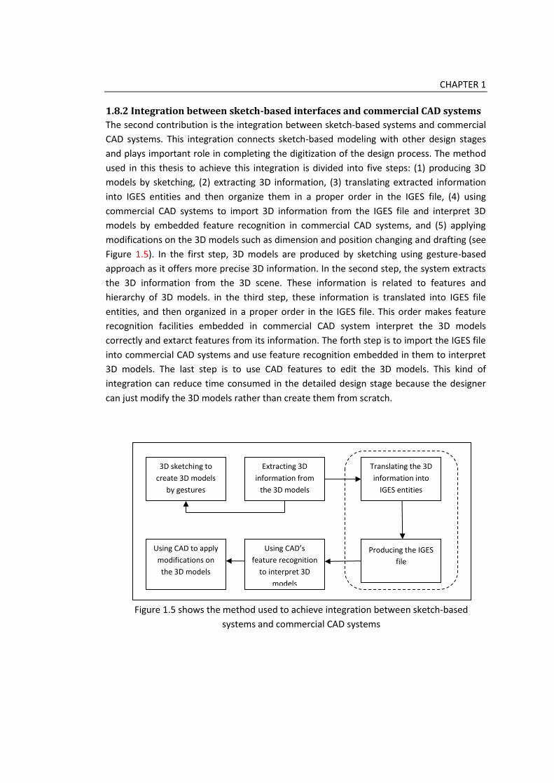
1.8.2 Integration between sketch-based interfaces and commercial CAD systems
The second contribution is the integration between sketch-based systems and commercial
CAD systems. This integration connects sketch-based modeling with other design stages
and plays important role in completing the digitization of the design process. The method
used in this thesis to achieve this integration is divided into five steps: (1) producing 3D
models by sketching, (2) extracting 3D information, (3) translating extracted information
into IGES entities and then organize them in a proper order in the IGES file, (4) using
commercial CAD systems to import 3D information from the IGES file and interpret 3D
models by embedded feature recognition in commercial CAD systems, and (5) applying
modifications on the 3D models such as dimension and position changing and drafting (see
Figure 1.5). In the first step, 3D models are produced by sketching using gesture-based
approach as it offers more precise 3D information. In the second step, the system extracts
the 3D information from the 3D scene. These information is related to features and
hierarchy of 3D models. in the third step, these information is translated into IGES file
entities, and then organized in a proper order in the IGES file. This order makes feature
recognition facilities embedded in commercial CAD system interpret the 3D models
correctly and extarct features from its information. The forth step is to import the IGES file
into commercial CAD systems and use feature recognition embedded in them to interpret
3D models. The last step is to use CAD features to edit the 3D models. This kind of
integration can reduce time consumed in the detailed design stage because the designer
can just modify the 3D models rather than create them from scratch.
Figure 1.5 shows the method used to achieve integration between sketch-based
systems and commercial CAD systems
3D sketching to
create 3D models
by gestures
Extracting 3D
information from
the 3D models
Translating the 3D
information into
IGES entities
Producing the IGES
file
Using CAD’s
feature recognition
to interpret 3D
models
Using CAD to apply
modifications on
the 3D models

CHAPTER 1
1.9 The Structure of this thesis
This thesis comprises of six chapters. Chapter 1 identifies the importance of sketching in
conceptual design stage and limitations that make CAD systems not suitable for sketching
activities. It also explains the need to improve sketch-based modeling to support idea
generation and how integration between sketch-based systems and commercial CAD
systems can be achieved. Chapter 2 describes the investigation of the sketching nature and
the structure of the improved sketch-based system. Chapter 3 describes the gesture design
and algorithms used in gesture recognition. It also describes case studies that were
conducted to make an initial examination for the system abilities. Chapter 4 describes the
integration between sketch-based systems and commercial CAD systems. Chapter 5
describes the evaluation test of the system. Chapter 6 shows results and discusses it.
Chapter 7 concludes the thesis with emphasis on the contributions and future work.

20
Chapter 2
Literature Review on Sketching
Roles in Design and Sketch-based
Interface and Modeling System
2.1 Introduction
Idea generation process plays a key role in the conceptual design stage. Sketching is the
main method used in idea generation process because its features that allow designers to
express their ideas freely. As CAD systems are not suitable for sketching activities because
it is designed for accuracy and efficiency, sketch-based modeling was developed to serve
the conceptual design stage. Sketch-based modeling was developed based on two
approaches: reconstruction and gesture-based modeling. Reconstruction approach
interprets the 3D models from 2D drawing. This approach is difficult in implementation
because it tries to imitate our brains in receiving the perspective. Gesture-based approach
user gestures to create primitives and extrusion. Gestures work instead of menus and
templates. Current sketch-based systems of this approach such as Teddy (Igarashi et al.,
1999) or SKETCH (Zeleznik et al., 1997) push the user to concentrate on the 3D modeling
process. Systems of the reconstruction approach on the opposite can’t interpret complex
sketches that contain assistant lines, annotations or shading. These graphical features are
used heavily by designers and it affects the sketch perceiving through the process.
The aim of this chapter is to design a sketch-based system which enhances the idea
generation process in the conceptual design process. Before designing the system, related
works to sketching process were reviewed. Sketches analysis and a questionnaire study
were conducted to collect more information about graphical features of sketches,
sketching behavior, and designers’ preferences about sketch-based systems. Results of

CHAPTER 2
these related works and studies helped in developing a sketching scenario which is the
base for the design of the sketch-based system in this chapter.
Related works in this chapter is divided into two categories: mental studies of sketching,
and graphical studies. Mental studies investigate the role of thinking and imaginary in the
sketching process. It also argued that there is a kind of integration between them. Sketches
present an external representation of the imagined concepts, and give immediate
feedback for the designer which enables him to realize relations, constraints, and errors.
This leads the designer to transform his idea and correct errors. From graphical side,
sketches are complex contents of graphical features and this complexity differs from a
sketch to another according to the designer. A designer also implements the
transformation of the idea by modifying graphical features in some ways.
The sketches analysis aims to find out graphical features that are used by designers, and
if design students and professional designers use them in the same way or not. This
analysis was conducted by analyzing 70 sketches of both design students (Product design
forum, 2010) and professional designers (Eissen and Steur, 2007). The findings show that
designers use 2D, 3D drawing, shading and coloring, annotations and assistant lines in
almost the same way. But this study didn’t offer information about sketching behavior or
how a designer approaches a sketch. The questionnaire study was conducted after that to
collect this kind of information, in addition to designers’ preferences about sketch-based
systems. Results show information about medium used in sketching and the ideation
process. It also gives information about graphical features that ensured the results got
from the sketches analysis. On the other hand, the designers’ preferences about sketch-
based systems showed that they prefer a 2D sketching space for free sketching before they
move into the modeling stage. They also find a complete control in the creation process
will be better than automatic 3D modeling.
From previous results, a sketching scenario was developed to describe the sketching
process. This scenario is divided into three stages: exploration, ideation, and sketch
finishing. In the exploration stages, the designer explores the problem and the design
space. In ideation process, he begins to visualize his ideas and gets feedback from his
drawing. In the last stage, he tidies up the sketch. This sketching scenario is the base for
the design of the sketch-based system presented in this thesis. This design of the sketch-
base system contains two interfaces, one for 2D sketching and the other is for 3D
modeling. The user sketches freely in the 2D sketching interface then transfers his sketch
as a reference image in the 3D modeling interface. After that he begins to create primitives
and extrusions to build a rough 3D model by using gestures. Gesture-based approach is

CHAPTER 2
used in the system because more 3D information can be extracted from the 3D scene. This
helps in integration between sketch-based systems and commercial CAD systems. The
system produces an IGES file which is transferred into commercial CAD systems. This file
isorganized in a specific order which makes features recognition embedded in the CAD
systems interpret the 3D models correctly.
2.2 Related Works
Design sketches are different from ‘drawing from the object’ (Tovey et al., 2003). They are
not drawing of something that already exists. They are representation of something that is
imagined in the mind of the designer. Ferguson (Ferguson, 1994) differed between three
kinds of sketches: (1) the thinking sketch, (2) the perspective sketch, and (3) the talking
sketch. The thinking sketch is used to focus and guide non-verbal thinking. The perspective
sketch is used to guide the draftsman in making a finished drawing. The talking sketch is
used in communication between technical people to clarify complex parts of the drawing.
This thesis concentrates on the thinking sketch as it is the one the designer uses in idea
generation process. Sketching process has two parts: the mental part, and the technical
part. The mental part contains the cognitive activities and the imaginary activities, while
the technical part is related to sketching behavior, tools, and graphical representation (see
Figure 2.1).
Figure 2.1 shows the sketching process parts
2.2.1 Sketching as a Mental Activity
The question of how designers think through sketching was and still one of the main questions encourages researches in design and cognition fields. Studying of human creative behavior depends usually on observations of designers while they are working or on analysis of design protocols. Most of studies presented developed process models to
Sketching process
Mental part Graphical part
Cognitive aspects Imaginary aspects

CHAPTER 2
describe designers’ behavior in design. Using of this kind of models offers more specific definition to the development of behavior in different design situations. French (French, 1998) presented a model to describe the design process and noted that there is a relation between cognitive activities of problem solving and conceptual design. This is because the designer attempts to solve problems and explore design space in the conceptual design using sketching. It is a kind of co-evolution between problem space and design space (Maher et al., 1996; Jansson et al., 1991). Exploration of design space is one of four stages composing the design process (Cross, 1994). This stage is followed by generation of design concepts where sketching is used. In these two stages, there are interactions between cognitive activities, design entities, and design process (Benami and Jin, 2002). According to Jin and Chusilp (Jin and Chusilp, 2006), the idea generation process is composed from four stages: analysis, generation, composition, and evaluation. In analysis stage, the designer understands the problem and investigates requirements and constraints. In generation stage, he begins to sketch out initial ideas quickly. He normally uses previous visual information from his memory. In composition stage, the designer starts to modify his ideas creatively by moving out of the iteration cycle. In evaluation stage, he asses concepts to design requirements and constraints and discusses how they are relevant, useful and good.
As a mental activity, sketching is related to some key terms such as thinking, imagining, visual thinking, and visual imagination. Thinking is the way that our brains realize and order information and thoughts (Tovey, 1989). Imagining is related to the seeing. While seeing is receiving the virtual information from outside, imagining creates virtual visual information inside brains by using existing visual information. This is what is called visual imagination, and visual thinking plays a key role in this by organizing these pieces of information together. It is like a ‘virtual world’ that a designer constructs in his mind (Schön and DeSanctis, 1986). Designers use sketching to transfer imagined visual information or this ‘virtual world’ into drawing on paper. This is why sketches are considered an extension of imaginary and an external representation of imagined objects (Tevrsky, 2008; Goldschmidt, 1991; Römer, 2001). And as the flow of ideas is quick and instantaneous, the designer uses sketching to record his ideas quickly for more inspections (Tevrsky, 2008).
Sketching offers a kind of circular feedback loop in this process between two kinds of pictorial representation: internal representation in imaginary and external representation on paper (Goldschmidt, 2003). Goldschmidt (Goldschmidt, 2003) expressed about that by an “interactive imaginary”. While a designer draws, he sees what he has drawn and discovers features and relations in his drawing (Schon and Wiggins, 1992). This kind of mental iteration is suggested also in (Maher et al., 1996; Adam and Atman, 1999). In this point thinking is integrated with imaginary because he thinks about features and relations, and then starts to imagines how to develop them. Ambiguity of sketches plays a key role in this feedback process (van Dijk, 1992). As sketches are freehand drawing and lines are drawn uncertainly, it inspires the designer with alternative solution (Scrivener et al., 2000).

CHAPTER 2
This is because the line can be interpreted in different ways and this is one of the strength of sketches in enhancing creativity.
After a designer gets the feedback from the sketch, he starts to edit or develop it. This process is called transformation. Goel (Goel, 1995) differs between two kinds of transformation: lateral and vertical. Lateral transformation is moving from one idea to a new idea. Vertical transformation is moving from one idea to a more detailed version of the same idea. Transformation also has a technical side which is related to the graphical representation of the objects.
2.2.2 Sketching as a Graphical Activity
Sketchpad with pencils is the common used medium in sketching because it allows a continuous sequence and the production of many ideas in a short time (Schon, 1999; Tovey, 1989). Graphical appearance of sketches is usually loose and informal and has a much amount of ambiguity. Graphical elements of sketches can be divided into two categories: physical and perceptual (Suwa et al., 1998). Physical category is related to the visual description of the element such as a line, circle, arrow, or word. The perceptual category is related to how the designer perceives the graphical elements such as shapes, sizes, and textures. For example, a set of lines can be perceived as a rectangle. Graphical elements specify the complexity of the sketch. Tovey (Tovey, 1989) define two levels of details in sketches: detailed and un-detailed. The un-detailed sketches contain abstract and general concept drawings and the detailed sketches contain in addition to that a part drawing. This simple model is not enough to describe the graphical side of the sketch precisely, so it was expanded in (Tovey et al., 2003) to a model of five level of complexity. According to that model, there are five levels of complexity in sketches. Sketches in level one just contain line drawing with no shading or coloring. In level two, sketches may contain annotations with the line drawing. In level three, sketches contain line drawing with rough shading and may contain annotations. In level four, sketches contain shading and may include coloring and graduation. In level five, the most complex level, sketches are colored, shaded, and may have annotations. It shows how the product looks like.
Another important issue is transformation of the sketch. Transformation is a process of sketch editing that the designer does to develop his idea visually. As it has a mental side related to idea development in the designer’s mind, it also has a graphical side related to how the designer edits the graphical elements to reach the final graphical appearance of the idea. There are several kinds of transformation that a designer can apply to a sketch (Prats et al., 2009). These kinds of transformation can be divided into three categories: transformations which are related to the structure of the sketch, transformations which are related to the elements of the sketch, and that related to the viewpoint. The first kind includes changes that a designer does and affects the idea or the structure of the sketch. The second kind includes changes that related to a graphical element such as adding or delete a line. The third kind is related to the viewpoint of drawing the sketch such as

CHAPTER 2
perspective or side view and this transformation is applied by changing it or drawing the same idea from another viewpoint to clarify it more.
Graphical appearance of the sketch has also a relation with creativity. High quality of sketches increases the perceiving creativity of ideas (Kudrowitz et al., 2012). This is because high quality sketches need less interpretation to be understood as a product. But this principle used normally by designers in the presentation sketches because he focuses on quickness and recording more ideas through idea generation process.
From previous studies, related to mental or graphical sides of sketching, it is apparent that these studies interested in understanding sketching from one side only. This may be because it was driven to serve some specific aims. For this reason, this thesis includes the next two studies: sketches analysis, and the questionnaire study. Sketches analysis study is important to collect more information about sketches and graphical features that are used by designers in drawing. It also can offer a conclusion about how designers draw their sketches. The second study, the questionnaire study is to understand how designer approaches a sketch and what a strategy he uses in ideation. It also offers information about designers’ preferences about sketch-based systems.
2.3 Analysis of Sketch’s Graphical Features
Graphical features means features used by a designer in drawing a sketch. These features include shading, coloring, and annotations. It also includes assisting features such as assistant lines and using primitives to simplify objects. The important of this analysis is that it helps to collect more information about the visual appearance of sketches which can help in understanding sketching in a better way. Good understanding means a better design of sketch-based system to enhance idea generation process.
This analysis aimed to collect sketches from undergraduate design students and professional designers to collect information about graphical features that they use in their thinking sketches. Analysis method was used as information required can be easily extracted from sketches rather than asking designers via a questionnaire or an interview. This is because a designer may be unconscious while sketching about what graphical features he mostly uses as he focuses on developing ideas. So he may give inaccurate answers if he was asked via a questionnaire or unclear and general answers via an interview. To start this analysis, a call was announced for undergraduate design students to participate their thinking sketches for an academic study that is related to sketching process by using a design forum website (Product design forum, 2010). Responses from design students were 50 sketches shows different products and style. For professional designers, many thinking sketches were collected by Koos Eissen and Roselien Steur and were included in their book (Eissen and Steur, 2007) as examples of professional designers work. These professional designers are belonged to different companies such as SMOOL Designstudio®, WeLL Design®, and Jan Hoekstra Industrial Design®. By choosing thinking sketches from this collection, 20 sketches were collected. 70 sketches are considered a

CHAPTER 2
good number to express all styles of sketching between design students and professional designers.
2.3.1 Analysis Method
The idea of this analysis is to find out if designers use some specific graphical features in
their sketches in the same way or not. This analysis is based on six graphical features: (1)
2D drawing, (2) 3D drawing, (3) shading, (4) coloring, (5) assistant lines, and (6)
annotations. The 2D drawing is the representation of the object from different viewpoints
such as side view or top view. The 3D drawing is using perspective to represent the object.
Using of shading and coloring normally add a reality to the sketch. Shading also includes
drop shading. Assistant lines are important to help designers in drawing an object.
Annotations are used to add more information about ideas. This information can’t be
expressed about by drawing. Figure 2.2 shows some sketches used in this analysis.
2.3.2 Results from Analysis
The two groups of sketches were coded and analyzed separately. Results of this analysis
showed that there is no big difference between novices or design students and
professional designers in using graphical features in their sketches. Nearly half of design
students and professional designers use 2D drawing to clarify the idea. The side view is the
most used in the 2D drawing. Around 90% of both groups use 3D perspective drawing to
visualize ideas. Figure 2.3 shows the using of 2D and 3D drawing by the both groups in
sketches. Graphical features such as shading, drop shading, and coloring are used by both
groups. The most obvious issue is that design students use shading more those
professional designers who depend on coloring more to add a kind of reality on their
sketches. Another important issue in results, professional designers didn’t use the drop
shading at all compared with 48% of design students used it. Figure 2.4 shows the usage of
shading, drop shading, and coloring in visualizing concepts. Assistant lines were used
heavily by design students and the professional designers. 60% of both groups used
annotations to add more information to the sketch. Figure 2.5 shows the usage of assistant
lines and annotations in sketches by design students and the professional designers.
From previous results, it is obvious that design students and professional designers use
the same graphical, geometrical, and assisting features in sketching with slight differences.
One of our notices about sketches is that more than 90% of sketches contain more than
one idea. This refers to how idea may be generated within the sketch.

CHAPTER 2
2
D d
raw
ing
3D
dra
win
g
Shad
ing
Dro
p
shad
ing
Co
lori
ng
Ass
ista
nt
lines
ann
ota
tio
ns
● ● ● ● ● ●
● ● ● ● ● ●
● ● ● ● ● ●
Figure 2.2 shows some examples of sketches used in the analysis and its analysis table
(Product design forum, 2010; Eissen and Steur, 2007)

CHAPTER 2
Figure 2.3 shows the using of 2D and 3D drawing by design students and the professional
designers in sketches
Figure 2.4 shows the using of shading, drop shading and coloring by design students and
the professional designers in sketches
0%
10%
20%
30%
40%
50%
60%
70%
80%
90%
100%
2D drawing 3D drawing
Design students
professional designers
0%
10%
20%
30%
40%
50%
60%
70%
80%
Shading Drop shading Coloring
Design students
professional designers

CHAPTER 2
Figure 2.5 shows the usage of assistant lines and annotation by design students and the
professional designers in sketches
2.4 Questionnaire Study on Sketching Behavior and Designers’ Preferences
about Sketch-based Systems
The aim of this questionnaire study is to collect more information about how a designer
sketches, what a strategy he uses, and what essential graphical features his sketches
contain. It also aims to find out what a designer prefers about sketch-based systems. Using
the questionnaire method here gives more specific information that can help in more
understanding of his behavior while sketching. This method is more powerful than
interview because it is easier in analyzing data and designers are controlled to give specific
answers in contrast to interviews where a designer can give general information. The
importance of this study is related to the need to study sketching behavior combined with
the graphical side of sketching. This helps in more understanding for sketching process
especially when it is connected to the development of sketch-based system. This is
because most of previous sketch-based systems focused on developing algorithms and
techniques to convert 2D drawings into 3D models. This study attempts to be more user-
centred.
0%
10%
20%
30%
40%
50%
60%
70%
80%
90%
Assistant lines Annotation
Design students
professional designers

CHAPTER 2
This questionnaire was distributed between design students, design researchers, and
designers. It was distributed online and invitations were sent to participants via e-mail.
Participants included undergraduate design students and design researchers in Brunel
University, and professional designers who works independently or in designs studios.
Around 100 invitations were sent to participants and 69 responds were received.
Participants are divided as follows: 27 design student, 5 design researchers, and 29
designers. Most of designers work in product and industrial design discipline.
2.4.1 The Design of Questionnaire
This questionnaire is divided into two sections. The first section contains questions related
to sketching behavior. The second section includes questions about designers’ preferences
about sketch-based systems.
In the first section, participants were asked about five categories of information to
provide: (1) tools or medium used in sketching, (2) ideation process, (3) graphical features,
(4) geometrical features, and (5) assisting elements. Tools of medium used in sketches are
pencil-and-paper, colors-and-paper, or CAD systems. Ideation process means how many
ideas the participant normally visualizes before reaching the final idea and how many ideas
he draws in the same piece of paper. Graphical features include shading, drop shading,
coloring, and annotations. These graphical features play a key role in realism of sketches.
In this study, geometrical features describe the way of drawing, 2D or 3D. For example, a
designer draws an object in perspective, so he uses the 3D drawing. Assisting elements
express about elements that are used to help designers to draw the final shape of the
object, such as assistant lines, or using 2D drawing to draw perspective. This information is
important to understand sketch’s contains which help in designing the sketch-based
system.
In the second section, as sketch-based systems are not popular commercially,
participants asked to watch two videos about Teddy (Igarashi et al., 1999) and SKETCH
(Zeleznik et al., 1997) to have a brief idea about this kind of systems if they have never
used one. After watching the videos, participants gave answers about their previous
experience with CAD or sketch-based systems. They also gave information about what they
think it will be preferable for developing a new sketch-based system that serve the
conceptual design stage in product design field. They chose answers between three
choices: yes, no, or not sure. This way of choosing specific answers helps in getting specific
opinions.

CHAPTER 2
2.4.2 Results of the Questionnaire Study
Results from the questionnaire study showed some useful information that should be
considered in designing a sketch-based system. Some of these results were expected and
others add new information. From the first sections, results are related to some categories:
tools, ideation, graphical features, geometrical features, and assisting features. For tools or
the medium a designer use in sketching, 66% prefer to use pencil and paper while 10%
colors. 20% of participants showed that they use CAD systems to visualize their ideas (see
Figure 2.6). For ideation process, 40% of participants answered that they normally visualize
less than 5 ideas before they reach their final idea, and 40% draw from 5 to 10 ideas to find
a concept that can be developed to a complete sketch. The rest of participants showed
that they draw more than 10 ideas before they can discuss which idea is better. But when
they have been asked about the number of ideas they normally draw on one piece of
paper, about half of participants replied that they draw from one to five ideas in each piece
of paper while less than 20% draw one idea on each piece of paper. Others draw more
than 5 ideas in each piece of paper (see Figure 2.7).
Graphical features include shading, coloring, and annotations which are used by
designers to clarify the idea and make it looks as a real product or to add more information
about it. From the study, most of participants use shading in their sketches to add the
feeling of depth to their ideas. Nearly 60% of participants use drop shading in their
sketches sometimes while 20% always use it to make their ideas look real. For coloring,
20% of participants normally don’t use coloring in their thinking sketches at all, while 60%
use it sometimes. Annotations are used to give more information about the idea and offer
a kind of literal communication through the sketch. Half of participants said that they
sometimes write notes in their sketches to add some information that can’t be added by
drawing. 25% of the rest showed that they always use annotations while they sketch (see
Figure 2.8).
Designers use geometrical features such as 2D and 3D drawing to visualize ideas. From
this study results, most of participants use 2D drawing to visualize their ideas or to help
them in drawing the perspective if the object is complex. Most of them also use
perspective to show the idea as it offers more reality to it (see Figure 2.9). Assistant lines
are used by approximately 90% of participants. Using primitives to simplify complex
objects also is a common feature that is used by most of participants (see Figure 2.10).
From the second section which is related to designers’ preferences about sketch-based
systems, results showed that about 30% of participants experienced sketch-based systems
before. Most of participants expressed that they prefer stylus and PC tablet rather than the

CHAPTER 2
mouse as this give the feeling of traditional method, pencil and paper. Half of participants
suggested that a separate 2D sketching interface will be better for developing ideas more
than a direct 3D modeling interface. They also prefer to control in the modeling process
rather than automatic creation directly after entering the stroke as teddy (Igarashi et al.,
1999). As they have a previous experience with CAD systems, half of participants suggested
that a system which offer them using their experience will be easier to user rather than
learning a new way in creating 3D objects. Figure 2.11 shows the results related to sketch-
based systems preferences.
From previous results, it is apparent that pencil-and-paper is still the most common
method used by designers to sketch. Also, most of designers add some shading to their
sketches to add some reality and feeling of the 3D to their ideas. This offers a better
interpretation of ideas rather than flat and simple ones. Using perspective is a popular
aspect in sketching and this may be because the feeling of the 3D that shows ideas as a real
products. Assisting features such as assistant lines are used heavily in sketches as the idea
is still not complete. It is also clear that stylus and PC tablet is a preferable method rather
than the mouse. Free 2D sketching before 3D modeling is suggested to help designers in
developing ideas in the conceptual design stage.
Figure 2.6 shows mediums used by designers in sketching
Mediums used by designers
Pencil-and-paper
Colors-and-paper
CAD systems

CHAPTER 2
Figure 2.7 shows ideation behavior of designers
Figure 2.8 shows graphical features used in sketches by designers
0%
10%
20%
30%
40%
50%
60%
70%
0-5ideas
5-10ideas
Morethan 10
One idea 1-5ideas
Morethan 5
Number of ideas to reach afinal concept
Number of ideas on one pieceof paper
0%
10%
20%
30%
40%
50%
60%
70%
Yes No Sometimes
Shading
Drop shading
Coloring
Annotation

CHAPTER 2
Figure 2.9 shows using of 2D and 3D drawing in sketches
Figure 2.10 shows the assisting features that are used in sketches
0%
10%
20%
30%
40%
50%
60%
Yes No Sometimes
2D drawing
3D drawing
0%
10%
20%
30%
40%
50%
60%
70%
Yes No Sometimes
Assistant lines
2D drawing
Using primitives

CHAPTER 2
Figure 2.11 shows designers’ preferences about sketch-based systems
2.5 Sketching Scenario
It is apparent from studies related to the mental side of sketching process that sketching is
an integrated process between thinking and imaginary. This integration happened when
the designer gets a feedback from the sketch, and begins to think about relations and
constraints, and then starts to imagine solutions of transformations to develop the
concept. This cycle of thinking-imagining-drawing is connected to the graphical side of
sketching. Studies related to the graphical side showed different types of transformations a
designer does to develop the visualization of the idea. From sketches analysis that has
been conducted in this thesis, results show that designers use graphical features in the
same way to express their ideas with slightly difference between novices or design
students and the professional designers. Design students may use some features more
than professional designers to ensure the idea, while professional designers express more
abstractly. From questionnaire study about the sketching behavior, results ensured the
results of sketches analysis and added new information about ideation process. It showed
that designers prefer to sketch several ideas in the same piece of paper. This helps them to
make comparison and offer a more critical feedback.
0%
10%
20%
30%
40%
50%
60%
70%
Yes No Sometimes
Using stylus/PC tablet
Previous CAD experience
Separate 2D sketching
Complete control in 3Dmodeling

CHAPTER 2
From previous results from related works, sketches analysis, and the questionnaire
study, a sketching scenario was developed to describe the sketching process. The aim of
this scenario is to offer a theoretical frame that can be used as a base for designing a
sketch-based system. This sketching scenario is divided into three stages: (1) exploration,
(2) ideation, and (3) sketch finishing. In the first stage, exploration, a designer begins to
explore problems and design space. Basically, this stage is related to mental activities
where a designer does much thinking and imagination about the idea but without
visualizing it using drawing. In the second stage, ideation, a designer starts to sketch his
ideas on the paper, and begins to receive feedback. The integration between imaginary
and thinking begins and graphical transformations occur. There is a kind of integration
between this stage and the exploration. Sometimes a designer finds himself needs to think
more about the problem according to realizing of relations and constraints. In the third
stage, a designer finishes the sketch by tidying it up which includes erasing assistant lines,
or emphasizing some profile lines. While a designer finishes his sketch, the cycle of
feedback still works. So, sometimes, he finds his idea still needs for more development, so
he moves back into ideation stage, or for more thinking about problem, so he moves back
into exploration stage. Figure 2.12 shows the sketching scenario.
Designers use the order of this scenario to sketch their ideas on paper. This makes it
useful in designing a sketch-based system according to this scenario. The sketch-based
system should offer an easy way for ideation and give the designer the chance and the
time to think and get feedback from drawing. It also should enable designers to use
graphical features freely. This is almost on the contrary of the current sketch-based
systems that push designers into 3D modeling process and consider ideas are existing
things to draw.
Exploration
Ideation
Sketch finishing
Figure 2.12 shows the sketching scenario

CHAPTER 2
2.6 System Structure
According to results from the questionnaire study, most of participants showed that they
prefer a separate 2D sketching interface to provide them a free method for sketching. They
also recommended a separate 3D modeling interface for more control in the 3D modeling
process. Making the system easy to use and in the shape that enables them to use their
previous experience with traditional CAD systems to learn it faster. From these
recommendations, the system structure contains two windows: one for 2D sketching, and
the other is for 3D modeling. This separation enhances the idea generation process in the
conceptual design stage. In current sketch-based systems, a designer can’t concentrate on
idea development because he is forced to think about 3D modeling in the same time as in
Teddy (Igarashi et al., 1999) and SKETCH (Zeleznik et al., 1997) which use gesture-based
modeling to create 3D objects. Also, in systems that use reconstruction approach, it may
provide more convenient way for sketching but it also is very limited in interpreting
sketches. It can’t interpret features such as assistant lines or annotations. It requires a tidy
and simple sketch to interpret it correctly. For all these reasons, it is better if the designer
can sketch and develop the idea first then begins to create it in a separate 3D modeling.
This will help designers to concentrate on ideas more and reduce the interruption of the
idea-flow.
One of the challenges of this thesis is to provide a kind of integration between sketch-
based systems and traditional CAD system. Achieving that can reduce time used in the
detailed design stage and offer availability for the 3D models produced by sketching to be
modified and refined by using CAD systems. This also can increase the competition abilities
of companies because they can reach market faster. In the sketch-based modeling this is a
key challenge because of the different nature between sketch-based modeling and CAD.
CAD systems use feature-based modeling in creating 3D objects. Reconstruction approach
extracts 3D objects from 2D drawing and uses surfaces to represent 3D models. This
provides flat 3D information in comparison to feature-based modeling. Gesture-based
approach works in a close way to feature-based modeling where predefined gestures
create predefined 3D objects. More 3D information can be extracted from 3D models
produced by using gestures. This information can be used in integration with CAD systems.
For these reasons, the 3D modeling interface in this system uses gestures to create 3D
models to provide a kind of integration with CAD systems.
The structure of this system contains two windows, one for 2D sketching and the other
for 3D modeling. In the 2D sketching window, the designer sketch freely in the same way
he does when he uses pencil and papers. After a designer finishes a sketch, he selects a
specific area of the sketch which contains the final idea and transfers it into the 3D

CHAPTER 2
modeling window. The transferred sketch is used as a reference image in the background
in the 3D scene to offer a reference for proportions of the idea. A designer begins to create
the 3D models quickly by gestures. This process uses algorithms for gesture recognition
and validation tests. Projection is used to position 3D models in the scene. After a rough 3D
model is produced, a designer can produce an IGES file to transfer his work into
commercial CAD systems for further refinements and modifications. This step uses an
extracting 3D information method to extract information from the 3D scene and an IGES
translator to translate 3D information into IGES entities. These entities are organized in
specific orders in the IGES file to be understood easily by feature recognition embedded in
commercial CAD systems. Figure 2.13 shows the structure of the system. The following
parts of this section discuss the system parts in much detail.
2.6.1 2D Sketching
There are many commercial 2D sketching interfaces such as Autodesk SketchBook Pro®
and Creo Sketch 2.0®. Actually these 2D sketching interfaces use interactive techniques
such as ‘rubberbanding’ and dragging rather than using freehand sketches (Lipson, 1998).
These interfaces provide digital methods for drawing, coloring, and shading. It help in
creating impressive sketches for presentation but not suitable for idea generation with all
ambiguity embedded in the process. It use many menus and buttons in the same way as
CAD systems use which make designers concentrate on the process rather than the idea.
For these reasons, developing a new 2D sketching interface that uses freehand sketching in
the same way of pencil and paper is essential.
This 2D sketching interface imitates the pencil and paper attitude. It is a white space
with just a menu bar in its top. This menu bar contains just the essential menus which
provide basic tasks such as open a new file, save, and exit. To draw, the user can use the
mouse or a stylus and PC tablet if available. There are no restrictions on the drawing
process as the designer has the complete freedom to draw or write as sketching on papers.
After a designer finishes his sketch, he can save it for more working later or transfer it into
the 3D modeling interface to start creating 3D models. This interface is compatible with
image file formats such as JPEG which make it easy to use images in the background for
redesigning. The designer sometimes uses this method to keep proportions of the design
by putting a picture under a trace paper. Figure 2.14 shows the 2D sketching interface.

CHAPTER 2
Figure 2.13 shows the structure of the sketch-based system
User Interface
2D sketching
3D modeling
Gesture entering
Gesture recognition
3D models construction
Gesture
Library
3D information extraction
IGES Translator
Produced IGES file
Sketch in 2D freely
Select the final idea
Transfer it to 3D modeling

CHAPTER 2
Figure 2.14 shows the 2D sketching interface
2.6.2 3D Modeling
This 3D modeling interface uses gesture-based approach to construct 3D objects. This
approach use predefined gestures to construct predefined 3D objects such as primitives
and extrusions. Using of this approach in this system is because it offers precise 3D
information that can be extracted from the scene and transferred into commercial CAD
systems to make a kind of integration between sketch-based system and commercial CAD
systems. The design of the 3D modeling interface is simple and a bit similar to perspective
view of traditional CAD systems. But instead of using menus and templates to create 3D
objects, it uses gestures. The interface is a white space with optional grid which can be
added to the scene or removed as the designer prefer. This grid represents the top view in
the perspective and by default all 3D objects are positioned on it as it is considered the
main reference plane. A new system for positioning 3D objects in the scene was
developed. This system allows users to add new reference planes in easy way by drawing a
line to specify its position. The system then positions all new 3D objects on this plane. This
way of positioning allows users not only create an object upon another, but also allows
them to position objects in different directions.
There are two modes in this interface: sketching and navigation. Sketching is the default
mode and through it designers create 3D objects. By choosing navigation mode, the
designer can navigate the 3D scene to see objects from different directions. Also, basic
viewpoints such as top, front, and side views are added to the system because designers
sometimes need to see the object from these views. These views can also be used in

CHAPTER 2
creating 3D objects if this seems convenient to the user. It works in the same way as
traditional CAD system. Another key feature of this 3D interface is using 2D sketches
produced in the 2D sketching interface as a background to help users to keep proportions
of the idea while they create 3D objects. Figure 2.15 shows the 3D modeling interface.
The 3D modeling process is divided into three stages as was shown in Figure 2.13. It
begins with entering gesture by the user. The second stage is gesture recognition. In this
stage, the gesture entered is classified and segmented, and then it is validated by
comparing it to gestures stored in the gesture library. After that, the specified 3D object is
constructed. This process is repeated with each 3D object is created.
2.6.3 Integration with Commercial CAD Systems
To integrate with commercial CAD systems, the system should produce a medium file that
contains the 3D information. In this case, the IGES file was chosen because it is widespread
used in exchanging data between current CAD systems. It also can carry more precise
information that is useful for feature recognition embedded in the commercial CAD
systems. Producing an IGES file need to develop an IGES translator to convert 3D
information into IGES entities. After translation is finished, there is a need to organize
these entities in a specific order within the IGES file. This specific order allows the system
to represent each 3D object in independently with its own points, edges, and surfaces. It
also specifies the relations between these contents. This way of organizing the IGES file
makes feature recognition embedded in commercial CAD systems to understand and
interpret 3D models correctly.
Figure 2.15 shows the 3D modeling interface

CHAPTER 2
2.7 Conclusion
This chapter investigates sketching process from its both sides: mental and graphical.
Previous works that investigated sketching as a mental activity argued that sketching is
related to thinking and imaginary. They considered it as an external extension of
thedesigner’s mind. It is external representation of imagined concepts. Thinking and
imagination integrate to understand the problem and produce visual information of
concepts. The feedback of sketches which perceive by a designer is useful in realizing the
relations and constraints. It makes errors apparent for the designer and gives him the
chance to correct them. Other works which studied the graphical side of the sketching
process differed between some levels of complexity in sketches related to graphical
features used by designers in drawing. It also found out how transformation of the sketch
while a designer edit an idea happens.
The graphical analysis of sketches that was conducted in this chapter aims to find out
what are the most graphical features used by designers and if they are used in the same
way or not. These features include 2D and 3D drawing, shading and coloring, assistant
lines, and annotations. Results from this analysis showed that design students and
professional designers use graphical features in the same way with slight difference.
Sketches of professional designers are simpler and more abstract. They rarely use drop
shadows while design students use drop shadows heavily to add reality to their sketches.
Also using the assistant lines differs from design students to professional designers.
After conducting sketches analysis, questionnaire study was important to collect
information about sketching behavior and sketch-based systems requirements. Sketching
behavior means how a designer approaches sketching and how he uses the graphical
features. Using graphical features in this context is different from sketches analysis
because here we can discover why and how designers use these specific features. Results
from the questionnaire study showed that pencil-and-paper is still the most common
method used by designers to sketch. Also, most of designers add some shading to their
sketches to add some reality and feeling of the 3D to their ideas. Using perspective is a
popular aspect in sketching and this may be because the feeling of the 3D that shows ideas
as a real products. It also showed that stylus and PC tablet is a preferable method rather
than the mouse. Free 2D sketching before 3D modeling is suggested to help designers in
developing ideas in the conceptual design stage.
From previous works and results from the sketches analysis and the questionnaire
study, a sketching scenario was developed. This sketching scenario describes the sketching
process in three stages: exploration, ideation, and sketch finishing. In exploration stage,

CHAPTER 2
the designer explores the problem and the design space. In the ideation stage, the
designer starts to visualize his ideas and receive feedback from sketches. Imaginary works
with thinking in the mind of the designer to correct errors and to develop ideas. After
theidea is developed, the designer finishes his sketch by tidying it up. In each stage, the
designer can move back to the previous stage to think about the problem again or to
transform the idea. This is according to what he receives from the sketch and how he
realizes the visualized idea. This sketching scenario helps in more understanding of the
sketching process and is useful as a base for designing a sketch-based system.
The design of the sketch-based system depends on designers’ preferences and attempts
to be more user-centred. The design of this system includes two interfaces, one for 2D
sketching and the other for 3D modeling. This separation between 2D sketching and the 3D
modeling offers more freedom for the designer to concentrate on the idea generation
rather than concentrating on the 3D modeling process. The designer begins with 2D
sketching and after finishing his sketch, he transfers his sketch to the 3D modeling to be in
the background. By using gestures, the designer begins to create a rough 3D model. As
integration between sketch-based is one of the challenges of this thesis, the system
produces an IGES file to transfer 3D information into commercial CAD systems. This file is
organized in a way that helps feature recognition embedded in commercial CAD systems to
interpret 3D models correctly.
In the next chapter, related works to gesture design and gesture recognition are
reviewed for more understanding about how to design successful gestures and algorithms
that are used in recognizing gestures. A user-centred approach is used to design more
friendly gestures that are extracted from the drawing way of the 3D objects. These
gestures also were examined in a focus group to be validated before implementing them in
the sketch-based system. Also, a two level algorithm is developed for more accurate
recognition of gestures. After implementing gestures and recognition algorithm, case
studies were produced as an initial validation for the sketch-based system.

44
Chapter 3
Gesture Design and Recognition
3.1 Introduction
Gesture design and recognition are key problems in the gesture-based systems. In the
gesture design, the developer attempts to design gestures which are easy to learn, to
remember, and to use. After that, the stage of the gesture recognition comes. Gesture
recognition is the way the system follows to understand the gesture entered by the user.
Recognition of a gesture is a complex task that needs robust algorithms to be done. This is
because the variety of the drawing styles of the users. Because of that, constraints were
added to the gestures to control the drawing styles of the user. This eases the process of
recognition but in the same time make learning gestures of a new system takes longer
time. This chapter aims to design gestures to create geometric primitives and objects of
extrusion. And then develop a recognition algorithm that produces a high accurate
recognition.
Related works in this chapter is divided into three sections: gesture design,
beautification and recognition process. Gesture design is related to how a developer can
design good gestures. This is the first issue developers should think about before thinking
about beautification and recognition. Beautification is a process which comes before the
recognition. The aim of this process is to convert the ambiguous entered strokes into
defined elements that a system can deal with. This process uses techniques such as
resampling, segmentation, and fitting (Olsen, 2009). After this process is done, recognition
of gestures begins. In recognition, gestures are classified and validated to be understood as
commands that the system does. In recognition, there are many algorithms presented to
produce accurate gesture recognition. These algorithms are online or offline algorithms
but in gesture-based systems the online algorithms are the kind used. Online algorithms

CHAPTER 3
can start work through the user entering gestures or wait till the process of entering
gestures is finished (Li et al., 2005).
Although gesture recognition is important in gesture-based systems, developers think
first about gesture design. Gesture design is related to how design a gesture that is usable,
easy to be remembered and learnt. Most works presented didn’t show how they designed
a gesture. This may be one of the reasons of Tian et al. (Tian et al., 2006) study to reveal
the characteristics that should be in a gesture. This study works as guidelines for the
gesture design presented in this chapter. The aim is to design gestures for 3D geometrical
modeling which is easy to use and remember and express about the task. To achieve this
aim, a 3d objects analysis was conducted to find out how they are drawn. Based on this
analysis and guidelines, gestures were designed for the system. Gestures are easy and its
design was driven from the 3D objects structure to express about the job.
Gesture recognition in this system used an algorithm of two levels to produce accurate
recognition. These two levels are classification, and validation test. In classification, a
gesture is classified and segmented. It is classified into three categories: straight lines,
opened curves, and closed curves. In the validation test the stroke number is recognized
first and then the suitable test is taken according to the stroke number. There are two
assistant tests that are taken to specify point position according to a circle or a polygon.
These tests are embedded in the most validation tests.
Positioning of 3D models in the 3D scene is one of the common problems in gesture-
based systems. This is because it needs to extract the 3D coordinates from the 2D drawn
gestures. Projection is the method used normally to do that. It calculates the Z coordinate
on a virtual 3D plane from a 2D coordinate by inversing it. Most of systems presented used
this approach with some different algorithms to enable the user to locate 3D objects upon
others. In this system presented in this thesis, a new method was used to enable the user
to locate the 3D object in any position in the 3D scene. This is by creating multi reference
planes according to the user need. It is easy to be created by drawing of single straight line.
After that, two case studies were designed and implemented. The aim of these two
case studies is to examine the system before conducting a user study to find out the points
of strengths and limitations. It also aims to examine the ability of the system that uses
gestures to construct complex products. Each case study examines specific features of the
system. The first case study examines the easiness of 2D sketching and the 3D modeling.
The second case studies examine the integration between the 2D sketching interface and
other 2D sketching applications, the easiness of producing more complex 3D models and

CHAPTER 3
positioning. Results of these case studies show that the system works properly. Creating
simple and complex 3D models is easy enough especially with using with the reference
planes that enable user to locate the 3D model accurately.
3.2 Related Works
Gesture-based interfaces began with the seminal work of Ivan Sutherland’s sketchpad
(Sutherland, 1964). This application used gestures to draw diagrams on a screen surface.
This approach is used currently in sketch-based modeling as diagram sketching. In sketch-
based modeling, many works used gestures to develop sketch-based systems for 3D
freeform objects (Igarashi et al., 1999; Karpenko et al., 2002; Tai et al., 2004; Kraevoy et al.,
2009) or for 3D geometrical objects (Zeleznik et al., 1997; Fang and Wang, 2008). In this
thesis, we focus on using gestures to construct 3D geometrical objects. The main problem
in this direction is how to define and recognize gestures (Olsen et al., 2009). Expectation
lists were presented to solve this problem (Igarashi and Hughes, 2001; Pereira et al., 2003;
Pereira et al., 2004; Murugappan et al., 2009). It depends on the user to confirm a right
recognition for his input gesture. This solution may present good gesture recognition
results, but it reduces the recognition options through the sketching process. For that
reason, there is still a need for robust algorithms for gesture recognition. But normally
before a system begins to recognize a gesture, it applies some beautification methods on
the gesture’s strokes. But before a developer thinks about recognition process, he should
think about gesture design. Related works in this section are divided into three categories:
gesture design, beautification, and gesture recognition.
3.2.1 Gesture Design
Gestures can be divided into two categories: motion gestures and pen gestures. Motion
gestures are gestures that use the physical movement of the user’s body to give
commands through motion sensing devices (Bowman et al., 2001). Pen gestures are
gestures that use mouse or stylus to be entered by a user a drawn or written marks
(Rubine, 1991). This section of the thesis focuses on designing pen gestures. The gesture
design and gesture-based interface will be used within this thesis to refer to pen gestures
and pen-based interfaces generally. Gesture-based interfaces are becoming widely used
between users because of the widespread of touch screens devices. The beginning of using
gestures through PDA devices backs to the launch of Apple Newton MessagePad which
was designed specifically for pen input (Long et al., 2000). After that, many gesture-based
interfaces were presented to be used with mouse and desktop computers for different
purposes (Briggs et al., 1992; Chatty and Lecoanet, 1996; Forsberg et al., 1998). It is
noticed in these applications that gestures were used for editing, navigation, and
positioning and menus and keyboards were used for other tasks. The using of menus and

CHAPTER 3
keyboard in a combination with gestures allows fast access for commands and limits the
number of gestures needed for the tasks that the system does (Zhao et al., 1995).
Researches on gesture design can be divided into two categories: developing tools for
designing gestures (Long et al., 2001; Hong and Landay, 2007) and searching for general
guidelines and users’ preferences for gesture design (Tang, 1991; Long et al, 1997; Tian et
al., 2006). The first category interests in developing software that can help designers to
design good gestures. One of good examples in this category is quill (Long et al., 2001). It is
software that is used in evaluating gesture design by analyzing the gesture that designers
enter from the point of the perception. It eliminates gestures that may be confusing for the
user or the computer. SATIN (Hong and Landay, 2007) works in a similar way to quill but it
has more abilities for gesture recognition. the disadvantage of this kind of software in that
it proposes gesture as one stroke which make it difficult for developers for 3D modeling to
use them in evaluating their gestures. This is because gestures used in 3D modeling mostly
consist from more than one stroke. For that reason, this section focuses on studies that
used a user-centred approach in gesture design although not many studies were
presented. The most method used in these studies is the questionnaire method to gather
data from users (Tian et al, 2006; Long et al, 1997). In a survey study about gestures, users
of PDA showed that they prefer gestures because they are convenient, efficient and
powerful (Long et al, 1997). They also encouraged developing more gesture application
which allow them to customize their own gestures. From participants in Tian et al. (Tian et
al., 2006), some guidelines were extracted for designing gestures. Gestures should be easy
for people to learn, remember, and to draw. As a gesture has a function, it should express
about this job clearly. This kind of guidelines is useful to be used by designers in designing
their gestures and to evaluate them. On the hand for the designing process, there are
three main stages to design a gesture (Ashbrook and Starner, 2010). The first stage is to
gather requirement or information about the function of the gesture. In the second stage,
the designer determines how a gesture can be mapped to its function. It means how the
design of the gesture can express about the job. In the last stage, the designer should
perform a test to evaluate the gesture before implementing it within the system.
3.2.2 Beautification
The aim of beautification process is to convert informal and ambiguous freehand strokes to
more formal and structured representations (Murugappan et al., 2009). This process is
sometimes called sketch filtering (Olsen, 2009). Beautification uses several methods in
converting vague sketched strokes into understood elements. These methods vary from
resampling or smoothing, segmentation, and fitting. Resampling is used to reduce noise in

CHAPTER 3
the sketched strokes by organizing spaces between key points in each stroke. Teddy
(Igarashi et al., 1999) used this method to divide the silhouette stroke into equal edges.
Resampling is connected to segmentation process because before modifying distances
between key points, key points of the stroke such as corners and darts should be
identified. In segmentation, many approaches were presented to do that such as using
drawing speed (Saga, 1995; Sezgin et al., 2004; Qin et al., 2000), curvature (Rattarangsi and
Chin, 1990; Lee et al., 1995), and using angle (Fang and Wang, 2008).
After finishing these processes, a stroke can be fitted into more meaning elements such
as curves. Curve fitting simplifies the data computation because it makes the data relative
for more defined form (Olsen, 2009). Many kinds of curves used in curve fitting such as
Bézier curve (Piegl, 1987; Eggli et al., 1997; Liao and Huang, 1990, Shao and Zhou, 1996), B-
spline curve (Chen and Yang, 1995; Wang et al., 2006), and implicit curve (marker et al.,
2006; Schmidt et al., 2005).
3.2.3 Recognition process
In the gesture recognition process, the recognizer attempts to segment strokes entered by
the user and classify them (Sezgin and Davis, 2008). Recognizers use two kinds of
algorithms for gesture recognition: offline or online algorithms (Li et al., 2005). Offline
algorithms treat a sketch or a gesture as an image and use image recognition methods to
understand it. This approach is mostly used in hand writing recognition (Bunka et al., 2004;
Tanaka et al., 1999). Online algorithms are the kind which is used in gesture-based
modeling (Zeleznik et al., 1997; Igarashi et al., 1999). This kind treats data in real time and
uses the variety of information that online systems provide for better recognition (Davis,
2007). This data contains strokes entered by the user, constraints, and how the shape
looks like. There are two categories of the online algorithms: asynchronous and
synchronous (Li et al., 2005). The asynchronous algorithms don’t start recognizing gestures
till the user finishes his drawing (Sezgin et al., 2001; Hse et al., 2004). In this approach the
user can’t know if his drawing is right or wrong till he finishes. If the user drawing is wrong,
he must start drawing from the beginning. Synchronous algorithms start recognizing
gestures while the user draws, so he can get an immediate feedback from the system (Ager
and Novins, 2003; Tandler and Prante, 2001).
Gesture recognition process has two levels of recognition: low level and high level
recognition (Olsen, 2009; Hammond and Davis, 2002; Yu and Cai, 2003). Low level
recognition classifies strokes into primitives’ shapes such as lines, curves, and circles
(Paulson and Hammond, 2008). High level recognition works with the meaning of the

CHAPTER 3
gesture which is combined from many strokes. It also deals with constraints that are added
to gestures to ease the recognition process.
Low level recognition can be divided into three categories: gesture-based, appearance-
based, and geometric-based recognition (Hammond and Paulson, 2011). Gesture-based
recognition begins first by attempting recognizing gestures that represents commands in
GRANDMA (Rubine, 1991). This application used a set of gesture for creation and editing of
shapes. It used some features to classify gestures by a linear classifier. This approach was
extended in (Long et al., 2000) which add more features to classify more gestures. This
kind of recognition in quite accurate but on the other hand the user should draw the
gesture in the same way every time. This adds a kind of constraints on the user which is
not convenient (Paulson et al., 2008). To overcome this disadvantage, some works were
presented to offer a free drawing atmosphere for the user (Wobbrock et al., 2007). The
appearance-based recognition concentrates on how the sketch or the gesture looks like or
the context. It doesn’t focus on the sequence of drawing and that makes entering gestures
easier for the user. Many algorithms are used in this kind of recognition such as matching
shapes against templates (Oltmans, 2007; Ouyang and Davis, 2009), and point-based
distance metrics (Kara and Stahovich, 2005; Wolin et al., 2009). Although this approach
provide a convenient way for drawing gestures but it need to store large amount of
samples to be matched with the data entered. The last kind of recognition is the
geometric-based recognition. This kind use geometric formulas to describe primitives
(Hammond and Paulson, 2011). It also allows the recognizer to use beautification
techniques in recognition process (Sezgin et al., 2007; Yu and Cai, 2003; Paulson and
Hammond, 2008).
3.3 Designing of Gestures
The main problem in using gestures is gesture recognition as it needs robust algorithms for
classifying and understanding gestures entered by the user. But there is a problem which a
developer should solve before starting work on recognition process. This problem is the
design of the gestures that will be used in the system. Although there are many works used
gestures in creating 3D geometrical objects (Zeleznik et al., 1997; Fang and Wang, 2008), it
didn’t explain how these gestures were designed or put general guidelines to do that. It is
not easy to design a gesture which it should be learnable, easy to remember and express
about job. Tian et al. (Tian et al., 2006) conducted a questionnaire study to discover the
characteristics that user-centred pen gestures should have. Results showed that gestures
with visual meaningful related to commands are easy to be remembered and learnt by the
user. Over 50% of participants considered that easy gestures should operate conveniently,
be drawn by one stroke, and be designed as a curve. Applying these characteristics may

CHAPTER 3
vary from an application to another especially in geometrical application where not all
gestures can be designed as a curve. But these characteristics can be used as general
guidelines for developers when they design gestures.
The aim of this section is to design gestures for 3D geometrical modeling. These
gestures should be able to speed up the sketching process and allows users to memorize it
easily by making it express about the function. To achieve that, we first analyzed the 3D
objects and its basic features, and different scenario used by the user to draw them. Then,
we design gestures based on results got from the 3D objects and its basic features analysis.
3.3.1 3D Objects Analysis
3D objects contain different kinds such as primitives, objects of extrusion, and objects of
revolution. In this section, we are interested in analyzing primitives and objects of
extrusion. Primitives are simple geometric shapes such as cube, cylinder, cone, sphere, and
pyramid. Usually, the designer uses primitives to structure the shape of the product by
simplifying it into its basic primitives (Eissen and Steur, 2007). Each 3D objects have some
distinct features that can be defined with, for example a sphere can be defined by its
radius and centre point. It is also obvious that to draw a primitive or an extrusion, a person
draw some strokes to combine the figure. A cylinder is drawn by two ellipses and two
parallel lines represent the height. But different persons use different sequences to draw
the same object. The approach which is used here is combining objects features and
drawing sequence to design a gesture that expresses about the job and is easy to be
remembered and learnt.
3.3.1.1 Sphere
Sphere is defined by its radius and centre point. Usually it is represented as a circle in 2D
drawing. In freehand sketching, the designer draws a closed curve which represents the
circle and may add shadows to add the feeling of depth. In single-line drawing, there are
two way to represent a sphere in this way: drawing a circle in the clockwise direction or in
the counter-clockwise direction. Figure 3.1 shows these two ways to draw sphere in 2D.
Figure 3.1 shows the two ways of drawing sphere in 2D

CHAPTER 3
3.3.1.2 Cylinder
Cylinder is a rounded 3D solid object that has a flat circular face at each end. It can be
defined with the radius and the centre point of its base and its height. It is represented in
perspective in 2D drawing by two ellipses that represent its two bases, and two lines that
represent its height and express about its solid body. Because it is more complex that the
sphere, there are many different sequences to represent it. Figure 3.2 shows some of
these different ways to represent a cylinder.
3.3.1.3 Cone
A cone can be defined with its base and height. Its base is a circular surface which can
define by its radius and centre point. The drawing of a cone in perspective in 2D is
represented by an ellipse of a circle that represents the base and two intersected lines in a
point to represent the body of the cone. It can be drawn in 3x3 different scenarios. Figure
3.3 shows some of these scenarios that can be used to draw a cone.
3.3.1.4 Frustum Cone
Frustum cone has two circular bases as the cylinder but they are different in radius. It is
represented in perspective drawing by two ellipses and two lines to show its body. It has
4x4 scenarios to draw it. Figure 3.4 shows some of these scenarios.

CHAPTER 3
Figure 3.2 shows some different scenarios to draw cylinder in 2D
Figure 3.3 shows some different scenarios to draw a cone in 2D

CHAPTER 3
Figure 3.4 shows some different scenarios of frustum cone drawing
3.3.1.5 Box
A box is a solid object with a square or rectangle base and sides. Each two surfaces are
parallel. It can be defined with the length and the width of its base and its height. It has 12
edges. This means it can be drawn by 12x12 different scenarios. But according to that a
designer may draw a base in one stroke; this number of scenarios can be increased further.
Figure 3.5 shows two of these different scenarios.
3.3.1.6 Pyramid
A pyramid is a solid object with a square base and its top is tapper point. It can be defined
with its base and height. The number of scenarios to draw a pyramid can vary because it is
the same like the box depends on the behavior of the designer. Figure 3.6 shows two of
these different scenarios.

CHAPTER 3
Figure 3.5 shows two of different scenarios of drawing a box
Figure 3.6 shows two of different scenarios of drawing a pyramid

CHAPTER 3
3.3.1.7 Extrusion
An object of extrusion is a solid object which can be defined by its base and height. There
are many scenarios to draw an extrusion in perspective according to the behavior of the
designer. Figure 3.7 shows two of different scenarios of drawing an object of extrusion.
Figure 3.7 shows two of different scenarios of drawing an object of extrusion3.3.2 The
Design of Gestures

CHAPTER 3
3.3.2 The Design of Gestures
Gestures play a key role in the system presented in this thesis because it provides a quick
and easy method for creating rough 3D models. Using gestures also reduces the need to
menus and buttons that are usually used in commercial CAD systems. Another important
issue is that using gestures to create 3D models provide more precise 3D information than
using reconstruction approach which makes it easier to integrate between sketch-based
systems and commercial CAD systems. This section shows the design of gestures which is
used in the sketch-based system described in chapter two. It also explains why they were
designed in this way based on the previous analysis of 3D objects. These gestures were
designed in the light of guidelines that were extracted from the questionnaire study of Tian
et al. work (Tian et al., 2006). These guidelines consider a gesture should be easy to be
remembered and learnt. It also should express about the job and easy to be drawn. Table
shows the gesture for each 3D object and explains their drawing sequences.
For this system, seven gestures were designed to create primitives and extrusion. The
first gesture is the sphere gesture to create a sphere. The user draws a circle which express
about the sphere. The second gesture is the cylinder gesture. It expresses a cylinder by the
base and the height of a cylinder. The user draws a circle to represent the base of the
cylinder and then draw a line which starts out of the circle to express about the height. The
third gesture is the cone gesture and it is very similar to the cylinder gesture but the line
which expresses about the height is drawn from inside the circle. The forth gesture is the
frustum cone gesture. Comparing to the cone gesture, it is the same but a second circle is
added to it to represent the second base of the frustum cone. So the user draws first a
circle, then a line begins from inside the circle, and after that a circle that contains the last
point of the line. The last three gestures can be considered one group of gestures because
they have similar features. This makes them easy for the users to remember.
The fifth gesture is the box gesture. A box is defined by its width, length, and height.
And normally when an individual draw a box, he starts from a corner. The gesture designed
for the box consists from three lines that express about its dimensions, and they intersect
in a point which express about its corner. Next to that, the pyramid gesture, where a user
draws a square to express about the base of the pyramid and a line to define its height.
This line starts from the middle of the square. The last gesture is the extrusion gesture. In
this gesture the user draws a polygon that represents the base of the extrusion and from
the out of the polygon he draws a line to define its height in the same way as the cylinder
gesture. Table 3.1 shows the gestures and steps to draw them.

CHAPTER 3
The object The gesture How to draw
Sphere
Draw a closed curve which represents a circle
in one stroke.
Cylinder
Draw a closed curve which makes a circle to
represent the base of the cylinder in one
stroke.
Then draw a straight line out of the circle to
represent the height of the cylinder.
Cone
Draw a closed curve which makes a circle to
represent the base of the cone in one stroke.
Then draw a straight line inside the circle to
represent the height of the cone in one
stroke.
Frustum
cone
Draw a closed curve which makes a circle to
represent the first base of the cone in one
stroke.
Then draw a straight line inside the circle to
represent the height of the cone in one
stroke.
Then draw a closed curve to make a circle that
represents the second based in one stroke.
Box
Draw the two lines represent the width and
the length of the box base in any order.
Then draw a line that represents the height
from the intersection point of the width and
the length of the base.
Pyramid
Draw a square which represent the base of
the pyramid.
Then draw a line starts from inside the square
to represent the height of the pyramid.
Extrusion
Draw the base of the extrusion object.
Then draw a line from out of the base to
represent the height of the extrusion.
Table 3.1 shows the gestures and steps to draw them

CHAPTER 3
3.3.3 Gesture Evaluation
After designing gestures, this design should be evaluated before it is implemented in a
sketch-based system. The need for an initial evaluation is because any change in the
gesture design in a post stage requires a change in the gesture recognition algorithms and
may be a change in the system structure. To do this evaluation, a mini focus group meeting
of 6 postgraduate design students from Brunel University, 4 from design department and 2
from mechanical Engineering department, was held. This method was chosen as its
common method in software design evaluation in addition to its flexibility, immediacy and
speed. This is very efficient for this point of research because in the case of refusing a
gesture there is a possibility to create a new design for it through the meeting by users.
This can enhance the design of gestures. In the beginning of this meeting, an introduction
about the aim of gesture, how it was designed, and how it works. After that two issues
about gestures were put to discussion. The first issue is these gestures are easy to be
remembered by users or not. The second issue is these gestures are easy to be drawn or
not.
With discussion papers and pencils were provided to make participants try gestures
drawing. Before the end of the meeting, participants were asked to evaluate each gesture
on as scale of five degrees. These degrees are strongly agree, fairly agree, neither, fairly
disagree, and strongly disagree. Results of this evaluation shows that gesture designed are
acceptable for participants from the easiness for remembering and drawing. All answers of
participants were between strongly agree of fairly agree. For the sphere gesture, all
participants strongly agreed that it is easy to be remembered as it imitate the way a user
draw it on papers. Most of them strongly agree it is also easy to be drawn (see Figure 3.8).
For the cylinder gesture, most of participants strongly agreed that it is easy to be
remembered and 66% of them strongly agreed that it is easy to be drawn (see Figure 3.9).
Results for cone and frustum cone gestures were similar. 66% of participants strongly
agreed that the gesture is easy to be remembered and learnt while the rest fairly agreed
that (see Figure 3.10). Most of participants find that the box gesture is fairly easy to be
remembered but in the same time they strongly agreed it is easy to be drawn (see Figure
3.11). For the pyramid gesture, most of participants strongly thought it is easy for them to
remember it. It also was easy to be drawn for most of them (see Figure 3.12).
For extrusion gesture, just half of participants found that it is very easy for them to
remember it while 34% though it is easy but not that much. For the drawing of the
extrusion gesture, half of participants expressed that the gesture is very easy to be drawn
(see Figure 3.13). From previous results, it is apparent that gestures designed for the

CHAPTER 3
system are easy enough to be remembered and drawn by users. This means these gestures
can be implemented in the system with confidence in its validity.
Figure 3.8 shows the results of the sphere gesture design evaluation
Figure 3.9 shows the results of the cylinder gesture design evaluation
0%
20%
40%
60%
80%
100%
120%
Stronglyagree
Fairly agree Neither Fairlydisagree
Stronglydisagree
Easy to remembre
Easy to draw
0%
10%
20%
30%
40%
50%
60%
70%
80%
90%
Stronglyagree
Fairly agree Neither Fairlydisagree
Stronglydisagree
Easy to remembre
Easy to draw

CHAPTER 3
Figure 3.10 shows the results of the cone and frustum cone gesture design evaluation
Figure 3.11 shows the results of the box gesture design evaluation
0%
10%
20%
30%
40%
50%
60%
70%
Stronglyagree
Fairly agree Neither Fairlydisagree
Stronglydisagree
Easy to remembre
Easy to draw
0%
10%
20%
30%
40%
50%
60%
70%
80%
90%
Stronglyagree
Fairly agree Neither Fairlydisagree
Stronglydisagree
Easy to remembre
Easy to draw
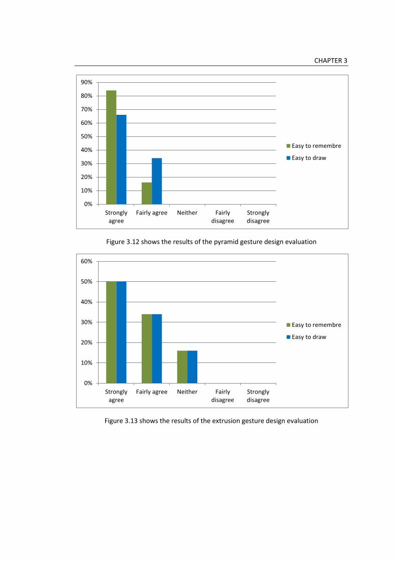
CHAPTER 3
Figure 3.12 shows the results of the pyramid gesture design evaluation
Figure 3.13 shows the results of the extrusion gesture design evaluation
0%
10%
20%
30%
40%
50%
60%
70%
80%
90%
Stronglyagree
Fairly agree Neither Fairlydisagree
Stronglydisagree
Easy to remembre
Easy to draw
0%
10%
20%
30%
40%
50%
60%
Stronglyagree
Fairly agree Neither Fairlydisagree
Stronglydisagree
Easy to remembre
Easy to draw

CHAPTER 3
3.4 Gesture Recognition
Gesture recognition is a common problem in gesture-based systems. Users tend to draw
gestures in different ways. Some draw it in a continuous way while others draw it as a
sequence of single strokes. Because of these different styles in drawing, gesture-based
systems need a method to recognize gestures correctly. As the expectation lists used in
such works (Igarashi and Hughes, 2001; Pereira et al., 2003; Pereira et al., 2004;
Murugappan et al., 2009) is not a very good solution because it limits the ability of the
system to recognize a wide range of objects, this system was directed to use algorithms to
recognize gestures. Developing a robust algorithm to recognize gestures is not an easy
process. An algorithm should deal with different drawing styles, analyze gestures correctly
and then recognize it. In this thesis, a two level algorithm is presented for gesture
recognition. This algorithm consists from classification, and validation test. The benefits of
the two levels are to get the most accurate results and to reduce time consumed by the
system to recognize gesture by narrowing the alternatives of gesture tests. In the first
level, the classification, a gesture is classified into three categories: straight lines, opened
curves, and closed curves. After that, the closed curves are tested to detect circles. If no
circles detected, they then are segmented. In the second level, there are two steps. The
first step is the stroke number recognition where the stroke number is calculated after the
segmentation process finished. This step narrows the number of the validation tests which
a gesture should pass. After that, the assigned validation test is taken. This assigned test is
one of several validation tests which include sphere test, cylinder test, cone test, frustum
cone test, pyramid test, and extrusion test. Figure 3.16 shows the two level algorithm.
3.4.1 Classification
Classification is the first level of the gesture recognition algorithm. In this level, a gesture is
classified first into three categories: straight lines, opened curves, and closed curves.
Opened curves are segmented into straight lines as gestures of the system don’t contain
curves. Closed curves are tested to detect circles. If there are no circles, the closed curves
then are segmented into straight lines. The algorithm which is used to classify gestures and
segment them was used before by Fang et al. (Fang et al., 2006) to segment gestures in
their work. In this thesis it is combined with a circle detection test to allow users to draw
more freely.

CHAPTER 3
3.4.1.1 Classification and Segmentation
This algorithm works in three steps:
1) Calculate the distance between the first point of the stroke and the end point of
the stroke.
where P is the points of the stroke
n is the number of the stroke pixels
d is the distance between the start point and the end points of the stroke
√
Equation 3.1
2) Calculate the distance between each point of the stroke and the line which is
connected by the first point and the last point to find the maximum
distance. Line is defined by the equation
Equation 3.2
where d is the distance between each point of the stroke and the line
| |
√ Equation 3.3
3) If the maximum distance of distances between each point of the stroke and the line is under 1% of the length of the line , so this stroke is a straight line. If it is between 1% and 170% of the length (Fang et al., 2006), so the stroke is an opened curve which means segmentation is applied by adding a new point p (see Figure 3.14). If it is more than 170%, so the stroke is a closed curve which means it should go through a circle detection test, and then if it is not a circle, it go through segmentation process. where max is the maximum distance of distances between each point of the stroke
and the line

CHAPTER 3
{
Figure 3.14 shows segmentation process
3.4.1.2 Circle Detection
A closed curve may be a circle or a polygon as some users draw a polygon with a
continuous one stroke. For this reason it is important to apply a circle detection test on
closed curves. The algorithm used in circle detection is divided into two steps:
1) Find the boundary of the stroke (height and width) and then calculate the
difference between height and width of the boundary (see Figure 3.15). If this
difference is less than an appropriate amount then the step two is taken.
Figure 3.15 shows the boundary of the closed curve

CHAPTER 3
2) Calculate the average of x values and y values of stroke points to find the centre
point.
Then calculate the distance between the centre point (avergeX, avergeY) and each
point of the stroke.
√ Eq. 3.4
After that find the average of these distances. If 80% of stroke’s points are located
in the range of distance+5 and distance-5, then it is a circle. Otherwise,
segmentation is taken.
3.4.2 Validation test
In this level, there are two steps: (1) stroke number recognition, and (2) test
implementation.
3.4.2.1 Stroke Number Recognition
In the segmentation process strokes are segmented and points are added. Resulted line
segments are stored in an array by its start and end points. The number of these points is
extracted from the array and according to this number; a validation test is applied for the
gesture. For example, if the stroke number is one, then a sphere test should be applied in
the gesture, if two, a cylinder test should be applied.
3.4.2.2 Test Implementation
The last step of the gesture recognition algorithm is implementing the validation test to
ensure that a gesture is valid and match one of the gestures used by the system. This step

CHAPTER 3
is based on the stroke number recognized in the previous step. This number specifies
which test should be taken (see Figure 3.16). There are different seven tests in this stage.
These tests are: (1) sphere test, (2) cylinder test, (3) cone test, (4) frustum cone test, (5)
box test, (6) pyramid test, and (7) extrusion test. These tests are based on the classification
process which happened in the first stage and on a test for point position according to a
closed shape to test if this point is inside a closed shape or outside. Classification process
classifies strokes into straight lines, or closed curves as the opened curves are normally
segmented into line segments. So the test first examines the stroke classification then
examines its physical features or the relations between strokes.
For the testing of a point position according to a closed shape, there are two conditions:
the shape is a circle or a polygon. In the case of the circle, the position of a point according
to circle is specified by comparing the distance between the centre point of the circle and
the point with the circle radius . If , then the point is out of the circle. If ,
then the point is inside the circle (see Figure 3.17).
In the polygon case, a line is produced between the point and the point which
has the maximum X value and the same Y value of the point . Then find out how
many times this line is intersected with the edges of the polygon. If the intersections
number is 0 or an even number, then the point is out of the polygon. If the intersection
number is an odd number, then the point is inside the polygon. Figure 3.18 shows the
case of the point and the polygon.

CHAPTER 3
Algorithm
Level 1 Classification
Level 2 Validation test
Sphere
test
Cylinder
test
Box test
Extrusion
test
Pyramid
test
Extrusion
test
No Yes No Yes No
Cone
test
Frustum
test
Extrusion
test
Number of strokes of the gesture defines which validation test should be
taken:
1 stroke 2 3 4 5 more than 5
If the gesture is valid, then the 3D model is created. If the gesture is not
valid, the scene is cleared from gestures and the user should re-enter the
gesture in a correct way.
Step 1
Step 2
Gestures are classified into three categories: 1) Straight lines 2) Opened curves 3) Closed curves Segmentation Circle detection
No Yes
Circle
Yes
Figure 3.16 shows the two levels of the algorithm used for gesture recognition

CHAPTER 3
Figure 3.17 shows the point inside and out of the circle
Figure 3.18 shows the different cases of a polygon and a point

CHAPTER 3
3.4.3.2.1 Sphere Test
This test is conducted if the stroke number is one. It is based on the classification process
result. If the stroke is a closed curve, then a sphere should be constructed. If not, then the
gesture entered is wrong and the user has to enter it again. In the case of the wrong
gesture, the screen is updated and cleaned to allow the user to draw directly.
3.4.3.2.2 Cylinder and Cone Tests
Cylinder and cone tests are connected to each other’s because the two gestures of the
cylinder and the cone consist from the same elements, a circle and a straight line. If the
stroke number is two, the system first examines the classification results. If the first stroke
is circle and the second is straight line, then this test is taken. If not, then the gesture is
wrong.
In the case of the classification results are correct; the system conducts the point position
test first to examine the position of the start point of the straight line according to the
circle. If the point is out of the circle, then a cylinder is constructed. If the point is inside the
circle, then a cone is constructed.
3.4.3.2.3 Box and Frustum Cone Tests
If the stroke number is three, the system examines the classification results first. If the
three strokes are straight lines, then a box text is applied. If the first and the third strokes
are circles and the second is straight line, then a frustum cone is applied. In the case of the
box test, the system examines the relations between the three strokes and distance
between points that specify the corner of the box. If these features are correct, then a box
is constructed according to the way of the drawing of its gesture. The box gesture has eight
positions to be drawn as the box has eight corners. Figure 3.19 shows these eight
positions.
On the other hand if the gesture expresses about a frustum come, then a frustum cone
test is taken to validate it. In the frustum cone test, the position of the straight line stroke
is tested by testing its start and end points positions according to the two circles. If the
gesture is correct, then a frustum cone is constructed.

CHAPTER 3
Figure 3.19 shows the positions of the box gesture
3.4.3.2.4 Extrusion and Pyramid Tests
If the stroke number is four or more, an extrusion test is taken. The extrusion test is based
on the point position test according to a polygon. It testes the start point of the last stroke
to find out if it is inside or out of the polygon. If it is out of the polygon, then an object of
extrusion is constructed. If the point is inside the polygon, then the stroke number is
checked again. If the stroke number is five, then a pyramid is constructed.
3.5 Positioning 3D Models
Locating the 3D models in the 3D scene in the sketch-based systems depends basically on
projection. This system use projection to convert the 2D points calculated from the
gestures to 3D points which help in locating 3D models. In this system, there is a main
reference plane which is used to project points on to it. This preference plane represents
the top plane in the perspective view. In addition to this reference plane, the system
allows the user to create infinite reference planes to locate 3D models on it. This kind of
easy creating reference plane according to the user needs offers a friendly way for
constructing 3D models.

CHAPTER 3
3.5.1 Projection
Projection is used in sketch-based systems to convert 2D points to 3D points that have Z
coordinate on to a virtual plane. In this system, this virtual plane represents the top plane
in the perspective view and the isometric projection is used to get the 3D coordinates of
the 2D points by inversing it. This method was used in (Chansri, 2011) which used
reconstruction approach for 3D modeling. Figure 3.20 shows the projection process.
Figure 3.20 shows the projection process
The isometric projection is defined by the equation:
[
] [
] [ ]
[
] [
] Eq. 3.5

CHAPTER 3
The virtual plane is defined by the equation:
Eq. 3.6
Where represent a normal vector, to a plane and is the normal
distance from the origin of the plane to the 2D plane. The determination of a vertex from a
2D point can identified from the equation:
[ ] [
]
[
] Eq. 3.7
3.5.2 Reference Planes
Placing all 3D objects on the main reference plane is not a practical way for designers. The
model a designer tries to construct usually contains objects upon, beside, behind, or under
another object. Previous work such as (Zeleznik et al., 1997; Fang and Wang, 2008) allowed
the user to construct an object on a face of another object. SKETCH (Zeleznik et al., 1997)
for example allows the user to create a cone upon a box by using specific algorithms to
snap the new object to the upper surface of the box. This way of snapping object to
another is convenient but it doesn’t work if the user wants to construct an object behind or
under the current one. It also doesn’t enable the user to create objects in a specific
position in the scene that he chooses.
For these reason, a new reference planes adding method was developed in this system.
It is completely under the user control. He can create a new reference plane, remove it,
and create a new one to construct 3D objects in the place he wants. These reference
planes can be parallel to the top, side, and front viewports which mean that the user can
create objects from any direction he finds it easier. The creation of the reference planes is
easy. The user just draws a straight line to specify where the plane should be created and
then press an icon to create it. After using of the reference plane, it can be removed to
back to the main reference plane, or a new one can be constructed. Figure 3.21 shows the
creation of the reference plane using the perspective view and the front view.

CHAPTER 3
Figure 3.21 shows the creation of the reference plane using the perspective view and the
front view
3.6 Case studies
One aim of this system is to improve the idea generation process in the conceptual design
stage. It aims to offer a convenient way for the designer to sketch freely and to generate
ideas without interruptions. The design of the system contains two interfaces: 2D
sketching interface and 3D modeling interface. In the 2D sketching interface, a designer
can sketch freely in the same way he does when using pencil and paper. It is a white space
for just thinking visually. The sketches produced in this interface can be used as a reference
image in the background of the 3D scene in the 3D modeling interface. Using sketches in
this way imitate the way a designer uses a picture under a trace paper. This helps the
designer to keep proportion of the design. In the 3D modeling interface, the designer uses
gestures to construct rough 3D models which they are transferred later into commercial
CAD systems for further modifications and refinements.
This section describes two case studies which were conducted by the researcher as an
initial experience of the system. The aim of the case studies is to examine the system
before conducting a user study to find out the points of strengths and limitations. It also
aims to examine the ability of the system that uses gestures to construct complex
products.

CHAPTER 3
3.6.1 Case Study 1
The aim of this case study is to examine some features that related to usability of the
sketching process. These features are:
The usability of the 2D sketching window. Using sketches as a reference image in the 3D modeling. The usability of the 3D modeling process.
The examination of these features is based on generating some ideas by using the 2D
sketching interface. One idea then is chosen to be transferred into the 3D modeling
interface. This sketch transferred is used as a reference image in the background to help in
keeping the proportions of the design while the user constructs the 3D models. In the 3D
modeling interface, gestures are used to construct rough and quick 3D model of the idea.
To do previous steps, a simple product was chosen to be sketched and modeled in this
case study. This product is a lamp with a shade. This product is usually used in commercial
CAD tutorials to teach users basic techniques. By using the 2D sketching interface, several
ideas were sketched by using tablet PC and a stylus. This sketch contains perspective and
side view drawing in the same way the many designers sketch. After that, one idea was
selected to be transferred into the 3D modeling. This idea was used as a reference image in
the background in the 3D modeling interface. By using gestures, the 3D model of the lamp
was constructed. This lamp is consisted of a box which represents its base, a cylinder which
represents the column that carries the lamp and the shade, and another cylinder which
represents the shade. First, by using the gesture of the box in the perspective view, a box
was constructed. After that, in the front viewport, we draw a line to specify a parallel
reference plane to use it in constructing the cylinder which represents the carrier of the
shade. Back to the perspective viewport, a gesture of the cylinder was drawn and a
cylinder was created. This step was repeated again to specify a new reference plane for the
cylinder that represents the shade. Figure 3.22 shows the steps of this case study.

CHAPTER 3
Figure 3.22 shows the steps of case study 1

CHAPTER 3
3.6.2 Case Study 2
The aim of this case study is to examine the ability of the system to construct more
complex 3D models. Building complex 3D models require easy positioning tool. Then, the
easiness of the reference plane using may be examined in this case study too. Features
which were examined in this case study are:
Integration between the system and pictures applications. Creation of more complex 3D models. The easiness of using reference planes. The examination of these features is based on using a 2D sketching application which
developed for IPad to create a quick sketch of a complex product. Then use this sketch
within the 3D modeling interface as a reference image to help in creating the 3D model.
After that, gestures and reference planes were used to construct the 3D model of this
complex product.
In this case study, a grinder was chosen as a complex product. First, the “Sketch”
application was used with an IPad device to draw a quick sketch of a grinder. This sketch
was saved as a picture and transferred by using e-mail to the 3D modeling interface. In the
3D modeling interface, this image was used as a background. The grinder consists of the
body, handle, and the blade. The body consists geometrically of an object of extrusion and
a cylinder. The handle and the blade are cylinders. There is also a small cylinder connects
between the body and the blade. The complexity of this product is not in the variety of the
geometrical objects, but it is in how they are ordered together to form the final 3D model.
First, a reference plane is created perpendicular to the main plane in the perspective view.
by using this new plane, the silhouette of the extrusion is drawn to construct the first part
of the body. Then, the same plane is used to create the handle but in the opposite
direction. After that, a new reference plane parallel to the main plane is constructed to be
used in creating the connection cylinder between the body and the blade. This cylinder is
located under the body. In the same way the blade is created. The last step is to construct
a new reference plane which is perpendicular on the main plane to create the second part
of the body. Figure 3.23 shows the steps of this case study.
This case study showed the using of reference planes to locate objects in the complex
models. It also showed how other 2D sketching applications can be integrated with the
system. This principle can be applied on the handmade sketches on papers. These sketches
can be scanned or photographed by a camera and then used in the 3D modeling interface.

CHAPTER 3
Figure 3.23 shows the steps of case study 2

CHAPTER 3
3.6.3 Results from Case Studies
These two case studies were to experience the system before conducting a user study
which may show more precise feedback. The aim of the case studies was to examine
specific features in the sketch-based system. These features include the easiness of
sketching and the 3D modeling, integration with pictures applications, and how is useful
the using of sketches as reference images in the 3D modeling interface.
The case study one showed how easy is sketching in 2D sketching window. It worked as
piece of paper in the traditional sketching. The user has the complete freedom to sketch
and generate ideas. Selecting a part of the sketch to make it a reference image in the 3D
modeling window is just like the selection process in any photo editing software. The using
of the reference image helps in keeping the proportions of the design and this is apparent
in the lamp model. Using gestures to create 3D models is easy, consume no time, and we
didn’t find out errors in gesture recognition process.
In the case study two, the system integrated successfully with sketches coming from
another application. This give the user the freedom to use the application he/she likes and
find it more useful for his work or even uses pencil and papers and then scan his/her work
to produce a digital version that can be used in the 3D modeling. The degree of complexion
of the 3D model makes the time consumed to create the model a bit longer than in the
first case study. This time consumed in locating the 3D objects correctly because in some
objects this wasn’t accurate enough. Reference planes worked properly as desired. It was
easy in creation, removing and locating, and the different view ports helped in assuring
this.
From previous results, it is apparent that the system works properly. Simple and
complex 3D models can be constructed easily. The using of reference planes plays a key
role in locating the 3D objects in the scene. The system integrated goodly with other 2D
sketching applications. All these results show that the system is valid to conduct a user
study that may give a more precise feedback from the user point of view.
3.7 Conclusion
This chapter investigated gesture design and recognition. In related works, it reviewed
previous works related to beautification, and recognition as these methods are used
basically in gesture-based system. Beautification is the process of converting the
ambiguous drawings into formal shape that can be understood by the system. This
happens by several techniques such as resampling, segmentation, and fitting. After this
process finishes, recognition of a gesture begins. The aim of recognition is to understand
gestures through the system context and match it to the gestures used by the system to

CHAPTER 3
validate it. If the gesture is correct, then the command is done. This review showed the
different kind of algorithms used in gesture-based systems. Algorithms are online or offline
but the online algorithm is the kind used in gesture-based systems. Algorithms also begin
work in different ways. Some begins while the user enters the gesture and others wait till
the entering process is finished.
Gesture design comes first when a gesture-based system is developed. The aim of
gesture design is to design gestures that easy to use, to be remembered, to be learnt, and
to express its task. These guidelines were extracted from users’ opinions by Tian et al. (Tian
et al., 2006). The aim of gesture design in this chapter was to design gestures for 3D
geometrical objects. To improve the understanding of how these objects are drawn, an
analysis of primitives and objects of extrusion was conducted. This analysis revealed that
users draw objects in several ways and sequences. It also showed the basic features of
each object which express about its geometrical structure. Results from this analysis were
used with the guidelines of Tian et al. study (Tian et al., 2006) to design gestures for the
system.
For gesture recognition, this system was provided with a three level algorithm to give
more accurate results. These three levels are classification, stroke number recognition, and
validation test. After the user enters a gesture, it is classified into straight lines, opened
curves, and closed curves. Segmentation process is embedded in this level to segment
strokes. After that, number of strokes is recognized to find out which validation test should
be taken. Validation tests are vary as 3D objects the system can produce but there is two
tests for detecting point position according to a circle or a polygon which is included in
most of validation tests. The aim of validation test is to ensure that a gesture is correct.
Another important issue in gesture-based systems is positioning. This is related to how
locate objects in the 3D scene by using coordinate information extracted from the 2D
drawn gestures. Inversing projection is used in many gesture applications and also in this
system to convert 2D coordinates into 3D coordinates on a virtual plane. But the problem
was what if the user wants to locate an object in another position which is not related to
this plane. A new method was developed by allowing users to create reference planes as
many as they need to locate objects to. These reference planes are sensitive to existing
objects’ surfaces which means that the user can attach it to an object or create it in the
space. This method provided an easy way for locating objects in the scene with an accuracy
which is near to traditional CAD systems.

CHAPTER 3
After that, two case studies were conducted as an initial experience of the system to
find out if it works goodly or not. These case studies aimed to examine specific features in
the system. The main features that the case studies should examine are:
The usability of 2D sketching and 3D modeling.
The integration between 2D sketching interface and other 2D sketching
applications.
The complex of 3D models that can be created by the system.
Feedback from the case studies showed that the system works in a good way. Integration
with other 2D sketching applications is successful. The creation of simple and complex 3D
models is easy and the reference planes method makes locating objects in the scene easy
and accurate.
The next chapter investigates the possibility of integration between sketch-based
systems and commercial CAD systems. Previous works related to feature recognition are
reviewed firstly, and then the integration method is presented. This integration method
uses IGES file format to transfer data from sketch-based system presented in this thesis
into commercial CAD systems. Autodesk Inventor® is used to recognize data transferred as
it is one of the most used commercial CAD systems. Case studies are conducted to ensure
that the Autodesk Inventor® recognize data with features and hierarchy information.

81
Chapter 4
Integration between sketch-based
interfaces and commercial CAD
systems
4.1 Introduction
Sketch-based modeling is a very important step towards a complete design process
digitization. For a complete digitization, integration of sketch-based modeling and
commercial CAD systems is being a necessity. This is because of the need of detailed
modification and refinement for the 3D models created by sketching. This integration can
speed up the design process and affect competition between companies in design and
manufacturing field. This chapter investigates the integration between sketch-based
systems and commercial CAD systems using IGES file format. It also investigate the ability
of transferring features and hierarchy information into commercial CAD systems which
make it possible to edit the 3D models instead of re-creating them from the beginning in
the detailed design stage.
Related works in this chapter focuses on understanding of feature recognition process.
Feature recognition is the process used by CAD, CAE, and CAM systems to integrate
between each others. But each category of these systems uses feature recognition in its
own way. For example, CAD systems use feature recognition to understand models
imported from other CAD systems and re-create them in a way that is understood by the
receiving system. CAM systems use it to recognize machining features in the models
imported from CAD. There are many approaches used in feature recognition such as graph-
based, volumetric decomposition, and hint-based approaches (Han et al., 2001). Feature
recognition also can be divided into two categories: platform-dependent and platform-
independent (Hayasi and Asiabanpour, 2009). Platform-dependant category use neutral

CHAPTER 4
file format such as IGES, STEP, and DXF to transfer data form one system to another and
this category is the one this chapter use in integration between sketch-based systems and
commercial CAD systems. So, more focusing on this category will be noticed in the related
works. Feature recognition also now is very common feature in commercial CAD systems
because this eases the transferring data between CAD systems from different vendors.
Commercial CAD systems play a key role in the design process. They are used widely in
the detailed design stage for 3D modeling and detailed drawing. CAD systems are divided
into two categories: surface modeling and solid modeling. This thesis focuses on the solid
modeling approach as this kind is used widely in product design. Sketch-based modeling
also has two approaches: reconstruction and gesture-based approaches. The gesture-
based modeling works in a similar way to CAD systems but it uses gestures instead of
WIMP system to create 3D models. The integration method presented in this chapter uses
the 3D models created by gestures which described in chapter 3. These 3D models are
transferred into commercial CAD systems by using IGES file format.
The integration method is divided into 3 steps: (1) extracting 3D information from the
3D scene, (2) producing an IGES file, and (3) using feature recognition embedded in
commercial CAD systems in recognizing features from the IGES file data. In the first step,
the 3D information is extracted from the 3D objects in the 3D scene. These 3D objects
were created by sketching using gestures. 3D objects are represented using boundary
representation. Extracted information is related to vertices, edges, surfaces, and how these
elements are connected with each other’s. The next step is to producing the IGES file to
transfer data into commercial CAD systems. In this step, the 3D information first is
translated into IGES entities and then is organized in the IGES file in a proper order. This
step requires developing an IGES translator to produce the IGES file. This translator
retrieves data from the storing array lists and organized it in the file. In the last step, the
IGES file is imported into commercial CAD systems. The order which the information uses
to be organized is designed specifically to make it easier for feature recognition embedded
in commercial CAD systems to recognize objects with its features easily.
In this chapter, three case studies were conducted to examine the integration method.
The main aims of the case studies are to examine if the CAD system can recognize the 3D
objects with features correctly and to find out if it is possible to apply modifications on
these objects. Each case study has 3 stages: using gestures to create a 3D model,
transferring these models by using IGES file format and importing them into a CAD system,
and then applying modification to the 3D model. Modifications vary from changing
dimensions and positions, drafting, to work with faces and edges to change the shape of

CHAPTER 4
the 3D model in some ways. Autodesk Inventor® was chosen as a widely used commercial
CAD system which uses solid modeling approach. It also supports feature recognition and
IGES file format. Results from case studies showed that using gestures to create 3D models
allows precise information to be extracted from the scene. This information includes the
feature and hierarchy information which is important for commercial CAD systems. it also
showed that the CAD system used recognized features and hierarchy information
successfully and allowed the modification to be applied on the 3D models.
4.2 Related Works
Integration between computer-aided systems is very important in the fields of design,
engineering and manufacturing because of the need for data exchange between different
systems and disciplines. Feature recognition is the process which is used to achieve this
integration. But before defining it, the feature term should be cleared. All computer-aided
systems used features in different way but the meaning of the feature differs according to
the type of application that uses it such as CAD, CAE, CAPP, and CAM. This difference in
natures between systems makes it difficult to achieve integration (Zhang et al., 2004).
Feature in CAD systems is one of the approaches for creating solid models. It provides a
large domain of geometric modeling and allows users to create complex models. In his
book, Zeid (Zeid, 2004) defined it as a shape and an operation to build parts. It describes
the characteristics of the part which carries significance meaning to a particular application
(Bhandarkar and Nagi, 2000). These applications vary from manufacturing, engineering,
assembly, to design. These characteristics may be related to one of five categories: form,
assembly, material, tolerance, and function (Shah and Rogers, 1988). Within the CAD
discipline, features are more related to form characteristic because it works on building the
part form the visual point of view.
Because of computer-aided systems have different natures and data produced by
systems are represented in different ways, it was a necessity to find a method to extract
information from this data and re-compose it in a way that the receiver system can
understand. Feature recognition is this method. It works by analyzing the data to its basic
elements and then re-composes it in a new order. For example, data produced from a CAD
system is a geometrical model, so feature recognition finds portions of the model which
match the characteristics of interest for the receiver application (Anderson et al., 2001).
These characteristics may be machining features as in the case of the receiver application
is a CAM system. Historically, feature recognition began from the desire to integrate CAD
with CAPP systems with the attempt of Grayer (Grayer, 1976) to develop a method for
automating NC programming. It didn’t recognize features but it was extended in the
seminal work of Kyprianou (Kyprianou, 1980) to produce successful recognition by

CHAPTER 4
investigating topological and geometric elements in CAD models and comparing them to
characterizing shapes. This method was applied mainly to 2-1/2D milling and then was
extended to 3, 4, and 5 axes (Corney and Clark, 1991; Nandakumar, 2000). Currently,
feature recognition uses many approaches but this section focuses on the three most used
approaches: graph-based, volumetric decomposition, and hint-based approaches (Han et
al., 2001).
The graph-based approach was first presented by Joshi and Chang (Joshi and Chang,
1988). This approach translates the B-Rep of the 3D model into a graph. For example,
vertices represent faces and arcs represent edges (Ansaldi et al., 1985; Marefat and
Kashyap 1990; Trika and Kashyap, 1994). Then these elements are re-composed together
to produce an understood pattern for the receiving system. The advantage of the graph-
based approach is that it is valid for using in several domains but it may suffer from being
slow because it does an exhaustive search for feature patterns in the boundary
representation data of a part (Anderson et al., 2001). In the volumetric decomposition
approach, the model is decomposed into a set of intermediate volumes first, and then
features are extracted and composed by combining volumes in a specific way (Woo, 1982;
Kailash et al., 2001). The decomposition process uses convex hull decomposition or cell
decomposition techniques (Babic et al., 2008; Gao et al., 2010). The hint based approach
supposes that any feature leaves a trace in the part boundary that provides a hint for the
feature. By discovering this hind, the feature can be extracted (Vandenbrande and
Requicha, 1993; Regli et al., 1995; Han and Requicha, 1997). Recently, it can be noticed
that there are more concentration on detailed feature recognition by using suppression
based method (Zhu and Menq, 2002; Cui et al., 2004; Gao et al., 2010).
The task of feature recognition is to extract feature data from a part by applying one of
the previous approaches or methods. There are two approaches to feature recognition:
platform-dependent and platform-independent (Hayasi and Asiabanpour, 2009). In
platform-dependant, feature recognition extracts features from a part which is
represented in a neutral file such as IGES (Ssemakula and Gill, 1988; Abouel-Nasr and
Kamrani, 2006), STEP (Han et al., 2001; Rameshbabu and Shunmugam, 2009), or DXF
(Ahmed and Haque, 2001; Meeran and Pratt, 1993). In platform-independent, the data is
extracted from the design features directly from a model created by design-by-feature
system. This section focuses of the using of platform-dependant approach. Neutral files are
widely used in exchanging data between CAD, CAPP, and CAM systems. IGES file format is
the most widespread file format used to exchange data. It also was used in many works
presented in feature recognition field. Ssemakula and Gill (Ssemakula and Gill, 1988) used
IGES file to integrate CAD with CAPP as a data transferring method from CAD systems to

CHAPTER 4
the receiving system. To achieve integration between CAD and CAM systems, IGES file was
also used (Abouel-Nasr and Kamrani, 2006; Jones et al., 2006). Abouel-Nasr and Kamrani
(Abouel-Nasr and Kamrani, 2006) presented an algorithm to extract manufacturing
information from models produced by a CAD system using IGES file format to transfer data.
This algorithm is designed for 3D prismatic parts that are created by using solid modeling
package by using CSG technique. Models then are transferred by using IGES file into a
feature recognition system developed in C++ language. Jones et al. (Jones et al., 2006) also
used IGES file to integrate CAD and CAM system. This method used wireframe models
produced by a CAD system and the hint-based approach to recognize features. From
reviewed works in feature recognition field, it can be noticed that most of works
concentrated on integration between CAD, CAPP, and CAM systems to speed up the design
process or to optimize the cost and quality of the models.
For integration between sketch-based systems and commercial CAD systems, to the
best of our knowledge, this kind of integration has not yet been reported. The known
method developed is that using macro file format to integrate between gesture-based
modeling and CAD systems (Cheon et al., 2011). The advantage of this method is that 3D
models are editable but the using of macro file format limits the benefits of this method.
On the other hand, integration between CAD systems themselves is very important in the
modern design process. This is because of the need to exchange data between different
systems. Feature recognition is a key tool to achieve this integration. For that reason, most
commercial CAD systems developed feature recognition tools which were embedded in
CAD systems to recognize models produced by other CAD systems. Within commercial CAD
systems, there are two kinds of feature recognition, automatic, and manual. In automatic
feature recognition, the system recognizes the features of a model without an intervention
from the user. In contrast in manual feature recognition, the user assigns features face-by-
face. Most commercial CAD systems have the two kinds in the same time to give the user
the chance to assign features in the case of failing in recognizing them automatically.
4.3 Integration Method
Commercial CAD systems are an essential tool in the modern design process. CAD systems
can be classified by their modeling approaches such as surface modeling and solid
modeling. Surface modeling approach represents a 3D model as a set of surfaces that
combine the outer skin of the model. Commercial surface modeling applications such as
Autodesk Alias® and CATIA® are more suitable for freeform product designs that have a lot
of curves and streamlines, e.g. automobiles. On the other hand, solid modeling approach
uses features such as extrusion, revolution, and drafting to create 3D models. This makes it
more suitable for products with mechanical engineering nature and also makes integration

CHAPTER 4
with CAM easier. Obvious examples of commercial applications of this approach are
SolidWorks®, Autodesk Inventor®, and ProEngineer®.
In general, a CAD system is goodly used in the detailed design stage but it is not suitable
for the conceptual design stage involving sketching activities because it requires a high
level of accuracy. Due to that, sketch-based interfaces for modeling were developed to
serve the sketching process. The goal of sketch-based modeling is to convert 2D sketches
into 3D models. There are two approaches to do that: reconstruction-based modeling and
gesture-based modeling. Reconstruction-based approach attempts to extract 3D models
from 2D sketches directly but resulting 3D models have flat 3D hierarchy information. It
represents 3D models in a set of surfaces or meshes. While gesture-based modeling
approach uses predefined gestures to create 3D models, but inside this approach there are
two directions. The first direction is to use gestures to create freeform 3D models like
Teddy (Igarashi et al., 1999). The other one is to use gestures to create primitives,
extrusion and revolution 3D models such as (Zeleznik et al., 1996). The second direction
works in a way which is close to solid modeling approach in commercial CAD systems but
instead of using menus and icons, it uses gestures.
Integration between sketch-based systems and commercial CAD systems provides a
complete digitalization for a design and manufacturing process. It also speed up the design
process by allowing designers to apply refinement and modification on the 3D models
produced by sketching instead of starting the detailed design models from scratch. Using
of the reconstruction approach for sketch-based modeling provides insufficient 3D
information such as hierarchy. In comparison, gesture-based modeling approach provides
more 3D information that can be extracted to be transferred into commercial CAD systems
to achieve integration. For this reason, a gesture-based approach was used in chapter 3 to
create 3D models. This section shows the method used to achieve integration between
sketch-based systems and commercial CAD systems. This method is divided into three
steps: (1) extracting 3D information from the 3D scene, (2) producing an IGES file, and (3)
using feature recognition embedded in commercial CAD systems in recognizing features
from the IGES file data. Figure 4.1 shows the integration method.

CHAPTER 4
Figure 4.1 shows the step of the integration method
4.3.1 Extracting 3D information
In chapter 3, gestures used to create 3D models. These models were located in the scene
using projections and reference planes. The system used the boundary representation to
represent 3D models. Boundary representation describes the 3D object in a term of its
boundary, namely the vertices, edges, and surfaces. Each surface should have its
orientation which is defined as the interior or exterior of the object (Abouel-Nasr and
Kamrani, 2006). To explain this, an object is defined by its faces. Each face is represented
by surface, edges, and vertices that bounded it. Each surface is represented by its vertices
and edges. Each edge is represented by two vertices: start vertex and end vertex. Due to
this rich representation of the 3D objects, we use boundary representation to represent 3D
models in this 3D sketching interface.
After completing each 3D model, an extracting process for the 3D information should
begin. Information extracted contains data about vertices, edges, surfaces, and how these
elements of the 3D object is connected together. Vertices information defines the number
of vertices in the 3D model and each vertex coordinates (x, y, z). Edges information defines
the number of edges in the 3D model, type of the edge (line, arc, or curve), and vertices of
the edge. For example if the edge is a line, so it has two vertices; start and end points. For
surfaces, each surface is defined by its vertices and edges that surround it in addition to its
type (e.g. planner or B-Spline surface). Another kind of information extracted is how this
model is described, closed or opened. A closed model is like a box and opened one is like a
sheet of metal. A mapping process is happening after that to classify the 3D model under

CHAPTER 4
feature definition such as extrusion or revolution using the extracted information for a
good representation. For example a box is classified under extrusion feature with a base
and extrusion value.
All information extracted from the 3D scene is stored in specific array lists that allow
the system to retrieve it when needed for IGES file producing. There are different array
lists for each category of information, such vertices, edges, and surfaces. In addition to
that, there are array lists which are specific to organize the storing process as for example
the number of vertices is different from an object to another. This helps in retrieving the
correct information and also is useful if the user decided to remove an object from the
scene after creation. It re-organizes data in the array lists in this case.
4.3.2 Producing an IGES file
The Initial Graphic Exchange Specification (IGES) is a neutral file format. The aim of this
format is to support the data exchange between CAD systems. Although this format was
first launched in 1980, it is the most widespread file format used between CAD systems till
this moment. The IGES file consists of standard five sections: Start, Global, Directory Entry,
Parameter Data, and Terminate (Kennicott, 1996). The Start section contains description of
the file contents and it can be left empty. Global section contains essential information
from the sender system such as the file name and directory, sender system name, and time
of producing the file. Directory Entity and Parameter Data sections are connected to each
other’s and have information about models entities. Terminal section is just one line at the
end of the file and it contains information about the number of lines of each section. The
using of the IGES file is because it is widely used file format in exchange data between
commercial CAD systems and most of these systems can produce and read it. Another
reason is that it enables a precise representation of the 3D objects as it has different levels
of entities that offer a representation for all elements of the object and it also offers
connections between its entities.
IGES file needs two translators, one in the sender system and another one in the
receiving system. The task of the sender translator is to translate 3D information into IGES
entities. The receiving translator is to translate IGES entities into a shape that is suitable to
the receiving sender to be understood. As the sketch-based system in this thesis is
considered a sender system and commercial CAD systems are considered receiving
systems, there is a need to develop an IGES file translator to translate 3D information
extracted from the scene into IGES entities which are ordered in the IGES file.

CHAPTER 4
4.3.2.1 Translation Process
Extracted information for each 3D model is divided into four categories: vertices, edges,
surfaces, and related information. Vertices information contains the number of points and
points coordinates (x, y, z). Edges information contains the type of the edge, and the
number of edges in the model. It also has clues to the edge’s points. Surface information
includes a description of the surface types, its points, and its edges. Related information
describes the faces number and if the model is a closed or opened shell.
This information is translated into different levels of entities that are related and
connected to each other’s. The first level of entities is the vertex list entity. Vertex list
entity represents the information related to the points of the 3D object. It coded first with
the number of the points in the object and then each point is numbered and represented
with its coordinates. The second level is the edge definition. This represents edge as a line,
circular arc, or curve. Each type represents different information. The third level is the
edge entity and this level is related to the edge type. In this level each edge is connected
with its type and its points in the vertex list entity. In the fourth level, the surfaces are
represented by its type, e.g. plane surface or B-spline. After surface representation, each
surface is connected with its edges by the loop entity. The next level is the face entity level.
A face can contain just one surface or more. In the face entity, faces are connected to its
surfaces and its loops. The last level is the shell level and it represents the whole 3D object.
It contains pointers into the faces of the objects in addition to information that explains if
the object is closed such as a box or opened like a sheet of metal. Table 4.1 shows the
translation of the 3D information into IGES entities.

CHAPTER 4
4.3.2.2 IGES Translator
As IGES file format require a translator to convert the 3D information into IGES entities and
build the file, an IGES translator was developed to do this job. The aim of the translator
developed in this section is to convert 3D information into IGES file according to the rules
explained in the previous section and organize these entities inside the text file. Writing an
IGES file begins with the creation of the head of the file. This head contains essential
information about the file and the sender system. It includes the Start and Global sections
Extracted information IGES file translator
Category Detailed information IGES entities Relation information
Vertices - Number of points - Points coordinates (x, y,
z)
- Vertex List Entity
Edges - Edge type
Line
Arc
Curve
- Line Entity - Circular Arc Entity - Composite Curve
Entity - Parametric Spline
Curve
- Number of edges - Edge Entity - Pointers to each edge type.
- Pointers to the vertex list entity and edge’s points inside it.
Surfaces - Surface’s types - Surface’s points
- Plane Surface Entity - Parametric Spline
surface Entity
- Surface’s edges - Loop Entity - Pointers to the edges of the surface in the edge list entity.
- Face Entity - Pointers to surfaces
- Pointer to loops.
Related information
- Faces number - Close of opened
- Shell Entity - Pointers to faces
Table 4.1 shows the translation of the 3D information into IGES entities

CHAPTER 4
of the IGES file. Next to that, the translator starts to recognize objects that will be
represented in the file and retrieve its information and translate it into IGES entities. Then
entities are ordered in the file as levels mentioned in the previous section. This step
happens object by object and after finishing translating all objects’ information, the
translator ends the file. Table 4.2 shows the steps that the translator does to translate 3D
information into IGES entities and then organize it in the file. Table 4.3 shows an example
of organizing box entities in an IGES file.
Step 1: Create the head of the IGES file that contain essential information about
the file
Step 2: Find the number of objects in the scene and classify them.
Step 3: For each object (loop):
- Translate vertices information into vertex list entity - Define each edge - Translate edges information and connect it to the vertex list that
contains object’s point - Translate surfaces into IGES entities according to its type - Connect each surface to its edges by loop entity - Define faces entities - Define the shell entity and connect it to its faces
Step 4: End the file
Table 4.2 shows the steps that the translator does to translate 3D information into IGES
entities and then organize it in the file
4.3.3 Importing IGES file into Commercial CAD Systems
Most commercial CAD systems have embedded feature recognition to recognize features
in models imported from other CAD systems that are developed by other vendors. The
existing of these facilities in commercial CAD systems enables users to move faster
between different systems and helps companies to integrate better through design and
manufacturing processes. The IGES file produced by the translator in the previous stage is
imported into commercial CAD systems and the feature recognition embedded in the CAD
systems are used to recognize features from the file. The aim of this step is to ensure that
features can be recognized successfully which means that the integration method works
properly. Another goal is to apply refinement and modifications on the recognized 3D
models. By succession in doing this, the time consumed in detailed design stage can be

CHAPTER 4
reduced as designers can just modify objects created by sketching instead of building
models from scratch.
Refinement and modifications include changing dimensions and positions of the 3D
models, drafting, and modifications applied onto faces and edges. These modifications can
change the final shape of the model and refine it to be more suitable for manufacturing.
Changing dimensions is like to change extrusion value or a cylinder height or radius.
Position changing can be related to other objects or to the scene itself. Drafting process
produces a slope in the object to be suitable for specific manufacturing process.
Modification applied onto faces or edges can be related to position of the shape. For
example a face can be pushed inside or pulled out. This can change the shape of the object
and affects its dimensions.

CHAPTER 4

CHAPTER 4
4.4 Case Studies
Integration between sketch-based systems and commercial CAD systems is one of the aims
of the system presented in this thesis. This integration aims to provide a complete
digitization for the design process stages by connecting sketch-based modeling with
commercial CAD systems. This also can reduce time consumed in the detailed design stage
by applying modification on the 3D models created by sketching instead of creating them
from scratch. This may lead to better position for companies and firms in the modern
competitive market by reaching markets faster.
This section describes three case studies which were conducted by the researcher to
examine the integration method presented in this chapter. There are two main aims of
these case studies. The first aim is to examine if the CAD system recognizes the 3D models
with feature and hierarchy information correctly or not. Features information express
about the way the 3D object is created by. So if the 3D object was created by extrusion,
the receiving CAD systems should recognize this and allows making modification in the
extrusion value. Hierarchy information describes the independent of 3D objects in the 3D
model. For example, a model contains one box and one cylinder, so the CAD system should
recognize the two objects as independent objects, not as one object.
The second aim is to examine the possibility of applying refinements or modifications
on the 3D objects recognized. Modifications include changing of dimensions and positions,
drafting, and working with faces and edges. Success in applying these modifications can
reduce time of the detailed design stage by just modifying the 3D models produced by
sketching. Each case study applying specific modifications on the 3D model transferred
from the sketch-based system.
Each case study has three stages: using gestures to create 3D models by using the 3D
modeling interface described in chapter 3, transferring 3D data by using the integration
method to a commercial CAD system, and then applying modification to the 3D models.
The Autodesk inventor® application was used in these case study because it is a wide used
commercial CAD system which uses solid modeling approach. It also support feature
recognition and IGES file format.
4.4.1 Case Study 1
The aim of case study 1 is to integrate with the CAD system to apply modifications on
dimensions and applying drafting on object of the 3D model. The first stage of this case
study is the creation of the 3D models by sketching. This is done by using gestures and the
3D modeling interface. First, a box is created and located on the main reference plane in
the 3D modeling interface. Then, the front viewport was used to construct a parallel

CHAPTER 4
reference plane to the main one. This new plane was used to locate a new box upon the
first box. Figure 4.2 shows the creation process in details. In the second stage, an IGES file
was produced by using the IGES file translator to transfer data into Autodesk Inventor®
application.
The last stage of the case study 1 is the importing the IGES file to the CAD application
and doing some modifications on the 3D models. Modifications which were applied in this
case study contain two kinds of changes. The first change is reducing the height of the
upper box. This is to ensure that dimensions can be changed in the detailed design stage
which can reduce time in this stage of design process. The second change is applying
drafting to its upper face. This is to ensure that adding some machining features such as
drafting can be applied which make it easier for the user to use 3D models produced by
sketching to integrate with CAM through CAD systems. Figure 4.3 shows the stage of
modifications in the case study 1.
Figure 4.2 shows the steps of the creation stage of case study 1
a) Drawing the box gesture
b) A box was created
c) Drawing the reference
plane gesture in the front
viewport
d) A new reference plane
was created
e) Drawing the second box gesture
f) The second box was created

CHAPTER 4
a) The 3D model produced
by sketching
b) The imported 3D model
in CAD system interface
Box 1
Box 2
Importing the
3D model into
Autodesk
Inventor®
c) Reducing the value of
extrusion for box 2
d) The 3D model after
reducing the value of
extrusion for box 2
Modify 1:
Reducing the
value of
extrusion
e) Applying drafting of the
upper face of box 2
f) The 3D model after
applying drafting of the
upper face of box 2
Modify 2:
Applying
drafting
Figure 4.3 shows the steps of modifications in the case study 1

CHAPTER 4
4.4.2 Case Study 2
This case study aims to apply modifications on the two 3D objects which compound the 3D
model. This way of applying modification will show the independent of the two objects and
the possibility of modifying them in separate way. Modifications in this case study contain
dimension and position changes. In the creation stage, a reference plane which is
perpendicular on the main reference plane was created firstly. And then, an extrusion was
constructed by gestures. To construct a cylinder upon the object of extrusion, a new
reference plane was created, parallel to the main reference plane. This new reference
plane was used to locate the cylinder on the upper face of the extrusion object. By creating
this cylinder, the first stage of this case study was finished and then the 3D data was
transferred to the CAD application by an IGES file. Figure 4.4 shows the steps of the
creation stage in this case study.
By importing the IGES file into Autodesk Inventor®, the modification stage started. In
this stage, the feature recognition embedded in the CAD software recognized the two
objects, the extrusion and the cylinder, successfully. The first modification is the changing
of extrusion value of the extrusion object by increasing it. And then reduce the height of
the cylinder. After that, change the position of the cylinder on the upper face of the
extrusion object. Figure 4.5 shows the steps of applying modifications on the 3D model in
the case study 2
Figure 4.4 shows the steps of the creation stage of case study 2
a) Drawing the reference plane gesture
b) A reference plane was created an extrusion gesture was drawn on it
c) Extrusion was created and reference plane gesture was drawn viewport
d) A new reference plane was created
e) Drawing the cylinder gesture
f) The cylinder was created

CHAPTER 4
study.
Figure 4.5 shows the steps of modifications in the case study 2
e) Decreasing the height of
the cylinder
f) The 3D model after
decreasing the height of
the cylinder
Modify 2:
Decreasing the
value of the
cylinder
a) The 3D model produced
by sketching
b) The imported 3D model
in CAD system interface
Importing the
3D model into
Autodesk
Inventor®
c) Increasing the value of
extrusion
d) The 3D model after
increasing the value of
extrusion for box 2
Modify 1:
Increasing the
value of
extrusion
g) Changing the position of
the cylinder
g) The 3D model after
changing the position of
the cylinder
Modify 2:
Changing the
position of the
cylinder
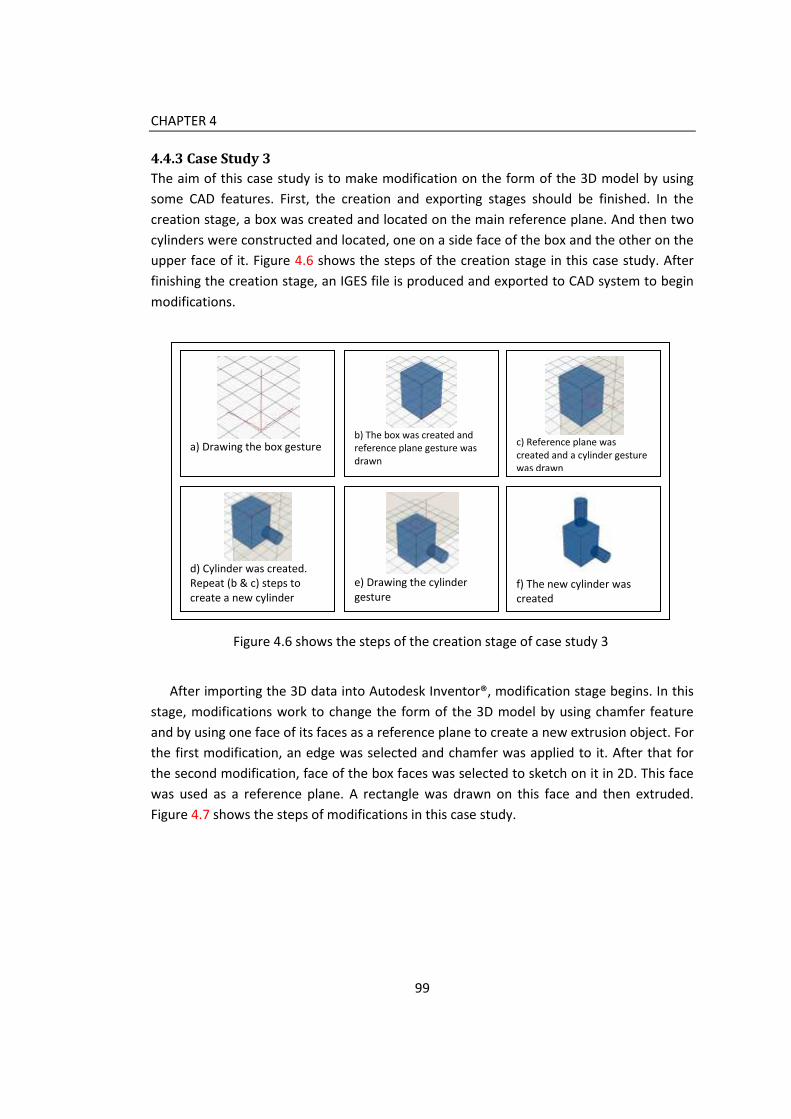
CHAPTER 4
99
4.4.3 Case Study 3
The aim of this case study is to make modification on the form of the 3D model by using
some CAD features. First, the creation and exporting stages should be finished. In the
creation stage, a box was created and located on the main reference plane. And then two
cylinders were constructed and located, one on a side face of the box and the other on the
upper face of it. Figure 4.6 shows the steps of the creation stage in this case study. After
finishing the creation stage, an IGES file is produced and exported to CAD system to begin
modifications.
After importing the 3D data into Autodesk Inventor®, modification stage begins. In this
stage, modifications work to change the form of the 3D model by using chamfer feature
and by using one face of its faces as a reference plane to create a new extrusion object. For
the first modification, an edge was selected and chamfer was applied to it. After that for
the second modification, face of the box faces was selected to sketch on it in 2D. This face
was used as a reference plane. A rectangle was drawn on this face and then extruded.
Figure 4.7 shows the steps of modifications in this case study.
Figure 4.6 shows the steps of the creation stage of case study 3
a) Drawing the box gesture
b) The box was created and reference plane gesture was drawn
c) Reference plane was created and a cylinder gesture was drawn
d) Cylinder was created. Repeat (b & c) steps to create a new cylinder
e) Drawing the cylinder gesture
f) The new cylinder was created

CHAPTER 4
Figure 4.7 shows the stage of modifications in the case study 3
e) Selecting a face to create
a sketch on it
f) Sketch a rectangle on the
selected face to be
extruded
Modify 2: Using
a face of the
model to
sketch on and
create an
extrusion
a) The 3D model produced
by sketching
b) The imported 3D model
in CAD system interface
Importing the
3D model into
Autodesk
Inventor®
c) Choosing an edge to
apply chamfer
d) The 3D model after
applying chamfer on an
edge
Modify 1:
Applying
chamfer on
one of the
edges
g) Extruding the drawn
rectangle
h) The 3D model after
extrusion process
finished

CHAPTER 4
4.4.4 Results from Case Studies
Integration between sketching interfaces and commercial CAD systems is important to
complete the digitization of the design process. From the first case study, the Autodesk
Inventor® succeeded in recognizing the two objects that compound the 3D model
transferred from the sketch-based system into the CAD system (see Figure 4.8).
Modifications which were applied on the 3D model were changing dimensions and
applying drafting. The two modifications were applied easily. In the second case study,
modification contained changing dimensions and position of a cylinder and changing the
value of an extrusion object. The last case study was to applying chamfer feature and using
one of the faces of the 3D model as a reference plane to sketch a new shape on it and then
extrude it. Results can be summarized in the following:
- Using gesture to create 3D models allows us to extract precise 3D information for
the 3D models. This information includes the feature and hierarchy which are
important for commercial CAD systems.
- Features and hierarchy information were extracted by a commercial CAD system
(Autodesk Inventor) successfully. Autodesk Inventor could read the independency,
features, and hierarchy of the 3D models.
- Modifications were easily applied on the 3D models. There was no problem in
changing dimensions and positions, working with faces and edges, and drafting.
Figure 4.8 shows the recognized hierarchy information from the case study 1

CHAPTER 4
From the previous results, it can be obvious that integration between sketching
interfaces and commercial CAD systems can reduce the time of the detailed design stage
because the user can use 3D models produced by sketching instead of creating new 3D
models from scratch.
Limitations were noted in using specific types of surfaces to represent the 3D model
such as cylindrical and planner surfaces. Inventor could not read these surfaces, but when
these surfaces were divided into a set of B-Spline surfaces it were interpreted successfully.
4.5 Conclusion
This chapter investigated the integration between sketch-based systems and commercial
CAD systems. In related works, it concentrated on understanding feature recognition
concepts and techniques. Feature recognition is the method used by CAD, CAM, and CAE
to understand and re-create models produced by other systems. The need for feature
recognition is because different systems have different nature and also different meanings
for features. For example, features mean creation and modeling ways in CAD systems
while it mean machining feature in CAM systems. There are three main techniques which
are used in feature recognition: graph-based, volumetric decomposition, and hint-based
techniques (Han et al., 2001). Feature recognition has two approaches: platform
independent and platform dependant. This chapter focused on the platform dependant
approach because it uses neutral file format such as IGES, STEP, and DXF to transfer data
form one system to another. Commercial CAD system also has feature recognition
embedded in it because exchanging data between CAD systems is very important in the
design process. So, most vendors developed and provided their applications with feature
recognition to understand files produced by other vendors’ applications.
An integration method between sketch-based systems and commercial CAD systems
was presented in this chapter. This method consists from three stages: extracting 3D
information from 3D models produced by sketching, transferring 3D data into commercial
CAD system, and using the feature recognition embedded in commercial CAD systems to
recognize objects and make modifications. In the first stage, the 3D modeling interface
presented in chapter 3 was used to construct 3D models by sketching by using gestures.
After that 3D information was extracted from the 3D scene. This information was stored till
the end of creation of the 3D objects and updated continuously to update any changes in
the scene. In the second stage, this information was translated into IGES entities and
organized in a specific way inside the IGES file. An IGES translator was developed for this
purpose. The aim of organizing data in that specific order is that to help feature
recognition embedded in commercial CAD systems to recognize features and hierarchy

CHAPTER 4
information easier from the IGES file. In the last stage, the IGES file is imported into
commercial CAD systems to be recognized and some modifications are applied. The goal of
applying modifications on the imported 3D model is to ensure that integration method
works properly.
To examine the integration method developed, three case studies were conducted.
There are two main aims of conducting these case studies. The first aim is to examine if the
CAD system recognizes the 3D models with feature and hierarchy information correctly or
not. The second aim is to examine the possibility of applying some refinements and
modifications on the recognized 3D models. Each case study has three stages: creating the
3D models by sketching, producing the IGES file to transfer data, and using a commercial
CAD system to recognize the 3D models and making modifications. In the first stage the 3D
modeling interface was used to produce 3D models by sketching. In the second stage, the
IGES translator was used to produce an IGES file. In the last stage, the commercial CAD
system was used to recognize 3D models from the IGES file and applying modifications. The
Autodesk Inventor® application was used because it supports the IGES file format and it is
wide used application in the design and manufacturing field. Modification applied to the
3D models contains dimensions and positions changing, drafting, and form modifications.
Results from case studies showed that using gesture to create 3D models allows us to
extract precise 3D information for the 3D models. This information includes the feature
and hierarchy which are important for commercial CAD systems. Using of this integration
methods makes the commercial CAD system (Autodesk Inventor®) recognizes 3D models in
a successful way with its feature and hierarchy information. The success of recognizing 3D
models allows the user to apply modifications. These modifications can vary according to
the system used. Making modifications also is useful in the design process by reducing time
consumed in the detailed design stage which offers companies an advantage in the
competitive market. Although the integration method worked properly, some limitations
were noticed when using other surfaces types except B-Spline surface in representing the
3D models.
In the next chapter, a user study is conducted to validate the sketch-based system. This
user study is divided into two parts: tutorial and questionnaire. The tutorial is to take the
user step-by-step with the system from navigation the basic features into practice 3D
modeling. The questionnaire is used to extract information from the users about gesture
design, 2D sketching interface and 3D modeling interface. After that, results are shown and
analyzed to find out the strengths and limitation about the system.

104
Chapter 5
User Study
5.1 Introduction
User study is a method to evaluate products or software applications by using real users in
the experiment. It helps developers to get direct feedback on their work. This chapter
describes the user study conducted to evaluate the sketch-based system presented in this
thesis. It also shows the results got from this user study. This user study consists of two
sections: a tutorial and a questionnaire. The aim of the tutorial is to familiarize the user
with the system, gives them instructions to construct 3D models, and asks them to do
some specific exercises. It contains three parts: navigation, idea generation process, and
3D modeling process. In the navigation part, the tutorial presents a description for the 2D
sketching interface and the 3D modeling interface and their contents. It shows the menus
and toolbars and their jobs for the user. In the second part, the idea generation process, it
describes how to use the 2D sketching interface to generate ideas and how to integrate
with other 2D sketching applications or with the 3D modeling interface. It shows the 2D
sketching interface features in details. In the last part, the 3D modeling process is showed
and explained. The tutorial in this part presents instructions for the user to create 3D
models, simple and complex. It also asks user to make some exercises which make the user
more familiar with the system. Before ending this part, the user is asked to generate ideas
and construct 3D models by his own.
The second section of this user study is the questionnaire which is used to get feedback
from the user about the sketch-based system. There are three features in the system
should be evaluated: gestures, idea generation process, and 3D modeling process. For that,
the questionnaire is divided into three sections. In the first section, gestures are evaluated
based on four factors: easiness to be remembered, drawn, and learnt by users, and the

CHAPTER 5
expression about the jobs they do. The second section is to evaluate the idea generation
process which is evaluated based on ideation, sketching practice, and integration with
other 2D sketching applications or the 3D modeling interface. The last section is to
evaluate the 3D modeling process. It is evaluated based on the easiness to create 3D
models, positioning them in the scene, navigation within the scene, and the assistant tools
which are provided in the 3D modeling interface.
This user study was conducted in Brunel University by using 20 of design students to
give feedback about the sketch-based system. Results showed that the system work goodly
and can support the idea generation process in the conceptual design stage. It also allows
users to construct 3D models in an easy way. The results of the first section of the
questionnaire related to gesture evaluation shows that gestures are acceptable from most
participants. Most of them strongly agreed that users can easily remember, learn, and
draw gestures. They also considered gestures express about their jobs clearly. For the idea
generation process, results showed that the system support the free sketching activity and
allows users to explore ideas conveniently. For the 3D modeling process, results shows that
it is easy to construct 3D models and locate them in the scene. Using navigation to
examine objects from different views is very useful for the user for more accurate 3D
modeling. Assistant tools such as grids and reference images help the user in the creation
of the 3D modeling and in locating objects in the scene.
5.2 User Study Description
User study is one of the methods used in user-centred interaction design to evaluate the
usability of a system or application by evolving users in testing it to get direct results
(Nielsen and Hackos, 1993). The aim of this user study is to evaluate the sketch-based
system presented in this thesis. The scenario of this user study is to prepare the user to be
familiar with the system first and then do some tasks. After that, he/she evaluates the
system through answering a questionnaire. According to that, this user study is divided
into two sections: a tutorial, and a questionnaire. Through the tutorial, the user can
investigate and practice the system. In the questionnaire section, the user answers
questions to evaluate gestures, idea generation process, and the 3D modeling.
5.2.1 Tutorial Description
The aim of this tutorial is to familiarize the user with system to be able to use it
conveniently. And after that he can practice exercises shown in the tutorial easily. The
tutorial is designed to be gradual in its contents. It is divided into four sections: navigation,
idea generation process, 3D modeling process, and real practice experience. In the
navigation section, the tutorial describes the contents of the 2D sketching and 3D modeling

CHAPTER 5
interfaces. It presents a general idea about how the system works. In the second section, it
describes in details, how the 2D sketching interface works to produce ideas and draw
sketches. It also shows how it integrates with other 2D sketching applications and with the
3D modeling interface. The 3D modeling section trains the user to construct simple and
complex 3D models by using gestures. The last section aims to push the user to generate
his own ideas and produce his sketches, and then convert them into 3D models.
5.2.1.1 Navigation Section
Because the sketch-based system presented in this thesis contains two interfaces: 2D
sketching and 3D modeling, this section shows the user the general items of the two
interfaces. The navigation of the 2D sketching interface shows that it is a white space for
free 2D sketching with one menu bar for basic menus. These menus contain file, edit, and
3D menus. The file menu is for open a file, save it, and exit. The edit menu is used to select
a part of the sketch or deselect it. This selection process is important when a user needs to
just use a part of his sketch as a reference image in the 3D modeling interface. The last
menu is 3D menu which is used to open a new 3D modeling window to start the 3D
modeling process. Figure 5.1 shows the 2D sketching interface.
The navigation of the 3D modeling interface shows that it is a white space with a grid
that represents the main reference plane. The main reference plane is the top plane in the
perspective viewport. This interface contains a menu bar in the top of the interface and a
toolbar in the bottom of the interface. The menu bar contains main menus as file and edit
in addition to another two menus: view and mode. The view menu is for adjusting the view
of the 3D interface by adding grid or a reference image in the background of the interface.
Figure 5.1 shows the 2D sketching interface

CHAPTER 5
The mode menus enable the user to move between sketching mode and navigation
mode. Sketching mode enables the user to create 3D models by gestures while navigation
mode enables him to rotate the scene to see models from different views. The toolbar
contains buttons that related to viewport control to enable the user to choose his
preferable viewport such as top, front, or left in addition to default perspective viewport. It
also makes the user control the creation of the 3D models and reference planes as creation
process is non-automatic according to users’ preferences drawn from the questionnaire
study conducted in chapter 3 about sketch-based requirements. Figure 5.2 shows the 3D
modeling interface with its menus and toolbar.
5.2.1.2 Idea Generation Process
This section aims to describe how the 2D sketching interface works. It works in the same
way the traditional medium – pencil and paper – works in traditional sketching process.
The user uses the mouse or a stylus to sketch freely on the white space. After finishing
sketching, he can export this sketch to be a reference image in the background of the 3D
modeling interface or save it for further modifications. It also enables the user to select a
specific part of the sketch to be saved or to be exported into the 3D modeling interface.
This interface also can integrate with other 2D sketching applications as it is compatible
with JPGE image format. This integration allows the user to import images as an underlay
to help him in sketching or use sketches produced by other applications to be edited.
Figure 5.2 shows the 3D modeling interface

CHAPTER 5
5.2.1.3 3D Modeling Process
This section was designed to enable the user to practice the 3D modeling. It contains three
parts which is designed to provide a good and gradual training for the user. These parts
are: gesture definition, modeling practice, and product modeling. In the first part, gestures
are defined and showed for the user to know the job of each gesture and how to draw it.
In addition to gesture used in creation 3D models, the gesture used for constructing
reference planes is explained in details to enable the user to achieve the most from the
system. The second section focuses on practicing 3D modeling. It begins with training the
user to create single primitives and extrusion, and then start to construct compound 3D
models by using reference planes. It aims to familiarize the user with the 3D modeling
process.
The third section aims to present a similar environment for real 3D modeling process here
there is a product or a sketch of a product needs to be modeled in 3D. In this section, the
user should follow instructions to create two real products: a lamp with a shade as a simple
product, and a container as a more complex one (see Figure 5.3). The steps of the tutorial
in this section give the user more experience about how to locate 3D objects in the scene
and how to use different elements of the 3D modeling interface for creation and
navigation the scene. After finishing this section, the user should be completely familiar
with the system and able to use the 2D sketching and the 3D modeling interfaces to
produce sketches and 3D models. In the last section of the tutorial, the user is asked to use
the 2D sketching interface to generate ideas about some imagined figures that can be a
Figure 5.3 shows 3D models used in the tutorial

CHAPTER 5
product or just a compound of 3D primitives. In this step, the user experiences the idea
generation process in real and when he finished this, he is asked to convert his idea to a 3D
model by using the 3D modeling interface. The aim of this section is to create a real
experience to get more accurate results about the usability of the system and how it
enhance the idea generation process in conceptual design. Figure 5.4 shows examples of
the 3D models produced by participants.
Figure 5.4 shows examples of the 3D models that were produced by participants
5.2.2 Questionnaire Description
The goal of the questionnaire is to get a direct feedback about the system from users. This
questionnaire is divided into three sections (see Figure 5.5) contain 43 statements about
the system. To answer the questionnaire, the user ticks a choice on a five levels scale.

CHAPTER 5
These five levels are: strongly agree, fairly agree, neither, fairly disagree, and strongly
disagree.
The first section of the questionnaire is the gesture evaluation. The aim of this section is
to evaluate gestures used to construct 3D models. Gestures are evaluated according to its
easiness to be remembered by users, to be drawn, and to be learnt. They are also
evaluated according to their expression about their jobs. Each gesture is evaluated through
4 statements decide previous features of the gesture.
The second section of the questionnaire focuses on the evaluating of the idea
generation process which happens in the 2D sketching interface. It gives statements about
the free sketching process, easiness of exploring ideas and the quick flow of ideas support
that the 2D sketching interface provides for the user. Also, it gives statements about the
possibility of modifications and editing of sketches and the variety of ideas that it allows
user to generate through sketching by using it. This section provides a feedback for the
main contribution of this thesis which is supporting the idea generation process of
conceptual design stage. The last section is related to the 3D modeling process. It focuses
on the easiness of constructing 3D models by using gestures. It also investigates if users
find the method of the reference planes is good for locating objects in the right location or
not. Other statements are related to the navigation process and how useful the reference
image and grids in the modeling process are.
5.3 Implementation and Results
5.3.1 Implementation
Implementation of this user study depended on 20 participants, 10 of postgraduate
students and 10 of undergraduate students in design department in Brunel University. This
The questionnaire
Gesture evaluation 3D modeling evaluation 2D sketching evaluation
Easy to remember Easy to learn Easy to draw Express about job
Ideation Sketching practice Integration
Modeling Positioning Navigation Assistant tools
Figure 5.5 shows the structure of the questionnaire

CHAPTER 5
number is enough to evaluate the system according to Virzi (Virzi, 1992) who found out
that 4 or 5 participants are enough to detect 80% of problems in software usability studies.
On the other hand, the variation in experience between participants can give clues about
the validation of the system for different levels of users. Each participant went through the
experience in individual. Participants received the tutorial and the questionnaire at the
beginning of the experience. They investigated the system through the tutorial first;
practice exercises, and then create their own sketches and 3D models. After that, they
answered the questionnaire. Each participant took from 45 min to 1 hour to finish the
tutorial and questionnaire.
5.3.2 Results
Results from the questionnaire study evaluate the sketch-based system presented in this
thesis from three sides: gestures, idea generation process, and 3D modeling process. The
questionnaire evaluates the easiness of remembering, learning, and drawing of each
gesture in addition to its expression about its job. Idea generation process is evaluated
based on the freedom it provides to the user to sketch and explore ideas, its integration
with other applications and the 3D modeling interface. The 3D modeling process is
evaluated based on the easiness of constructing the 3D models and locating them in the
right location. The navigation through the scene and different viewports are considered
through evaluation as essential factors in the 3D modeling.
5.3.2.1 Evaluation of Gestures
The sketch-based system uses seven gestures to create primitives and objects of extrusion.
Each gesture is evaluated based on four factors: easy to be remembered, easy to be drawn,
easy to be learnt, and expression about its job. The first gesture is the sphere gesture
which is a closed curve represents a circle referring to the sphere. All participants strongly
agreed that the gesture is easy to be remembered and learnt by users. 80% of participants
considered drawing the sphere gesture is very easy while 70% thought it is expressing
about its job clearly (see Figure 5.6). For the cylinder gesture, 70% of participants strongly
think it is easy to be remembered and drawn while most of them see it very easy to be
learnt by users. Half of participants agreed strongly that it expresses about the job while
the other half agreed that fairly (see Figure 5.7).
Cone gesture is the third gesture in the system gesture set. It is a circle represents the
base of the cone and a straight line begins from inside the circle referring the height of the
cone and its direction. 80% of participants strongly find it easy to be remembered, learnt,
and drawn by users while others fairly agreed that. 70% of them think it completely
expresses the cone while others fairly think this (see Figure 5.8). The frustum gesture is a

CHAPTER 5
more complex than the cone gesture as the user should add a second circle to refer the
second base of the frustum. Although that, all participants strongly agreed that it is easy to
be learnt and 90% of them strongly agreed it is easy to draw it while others fairly agreed
that. 70% of participants strongly agreed that the gesture is easy to be remembered while
others fairly agreed that. For how this gesture expresses about the job, half of participants
strongly think it is expressing and the other half fairly think this (see Figure 5.9).
Figure 5.6 shows the results of the sphere gesture evaluation
0%
20%
40%
60%
80%
100%
120%
Stronglyagree
Fairly agree Neither Stronglydisagree
Stronglydisagree
Easy to remembre
Easy to draw
Easy to learn
Express about the job

CHAPTER 5
Figure 5.7 shows the results of the cylinder gesture evaluation
Figure 5.8 shows the results of the cone gesture evaluation
0%
10%
20%
30%
40%
50%
60%
70%
80%
90%
100%
Stronglyagree
Fairly agree Neither Stronglydisagree
Stronglydisagree
Easy to remembre
Easy to draw
Easy to learn
Express about the job
0%
10%
20%
30%
40%
50%
60%
70%
80%
90%
Stronglyagree
Fairly agree Neither Stronglydisagree
Stronglydisagree
Easy to remembre
Easy to draw
Easy to learn
Express about the job

CHAPTER 5
Figure 5.9 shows the results of the frustum gesture evaluation
The fifth gesture among the gesture set is the box gesture. This gesture consists of
three straight lines expressing about the width, length, and height of the box. 80% of
participants strongly agreed it easy to draw and learn it while others fairly think this. 70%
of them strongly consider it easy to be remembered by users while others fairly show their
agreement. For how this gesture expresses about the job, half of participants strongly think
it is expressing and the other half fairly agree this (see Figure 5.10). The next gesture is the
pyramid gesture. 70% of participants considered it very easy to be remembered, drawn,
and learnt by users while others fairly think that. 80% of them think it expresses about the
job strongly while 10% consider this fairly, and the other 10% neither agreed that nor
disagreed (see Figure 5.11).
The last gesture is the extrusion gesture. It consists of a closed polygon to refer the base
of the extrusion and a straight line to refer the extrusion height and direction. For the
easiness of remembering the gesture, half of participants strongly agreed this easiness
while 30% of them fairly agreed that. 20% of participants neither agreed that nor
disagreed. For the easiness of drawing the gesture, 50% of participants considered it very
easy, 20% found it easy enough, and others expressed neutrally about that. 70% of
participants considered the gesture is very easy for users to learn it while 10% of them
agreed that. Most of participants think it expresses about the job (50% strongly agreed and
30% fairly agreed that) while others neither agreed nor disagreed (see Figure 5.11).
0%
20%
40%
60%
80%
100%
120%
Stronglyagree
Fairly agree Neither Stronglydisagree
Stronglydisagree
Easy to remembre
Easy to draw
Easy to learn
Express about the job

CHAPTER 5
Figure 5.10 shows the results of the box gesture evaluation
Figure 5.11 shows the results of the pyramid gesture evaluation
0%
10%
20%
30%
40%
50%
60%
70%
80%
90%
Stronglyagree
Fairly agree Neither Stronglydisagree
Stronglydisagree
Easy to remembre
Easy to draw
Easy to learn
Express about the job
0%
10%
20%
30%
40%
50%
60%
70%
80%
90%
Stronglyagree
Fairly agree Neither Stronglydisagree
Stronglydisagree
Easy to remembre
Easy to draw
Easy to learn
Express about the job

CHAPTER 5
Figure 5.12 shows the results of the extrusion gesture evaluation
5.3.2.2 Evaluation of Idea Generation Process
Idea generation process is evaluated according to three factors: ideation, sketching
practice, and integration with other 2D applications and the 3D modeling interface. The
ideation is evaluated based on four sub-factors: the freely sketching, exploring ideas,
supporting the quick flow of ideas, and concentration on idea generation. For the freely
sketching, all participants strongly considered the 2D sketching interface support the
freedom of sketching with its imitation to the traditional sketching tool, pencil and papers.
60% of participants strongly agreed that it allows user to explore ideas while others of
them fairly agreed that. Most of them strongly think that it supports the quick flow of ideas
and 60% strongly agreed that it allows users to focus on idea generation (see Figure 5.13).
The sketching practice is evaluated based on the easiness of producing many ideas by
using the 2D sketching interfaces and the easiness of editing sketches produced. All
participants strongly agreed that it is easy to produce many ideas and edit them by using
the 2D sketching interface (see Figure 5.14). The last factor is integration. For the
integration with other 2D sketching applications, 60% of participants strongly agreed that
integration with other 2D sketching is useful and successful while other fairly agreed that.
For the integration with the 3D modeling interface, 70% of participants found it very
successful while others fairly think that (see Figure 5.15).
0%
10%
20%
30%
40%
50%
60%
70%
80%
Stronglyagree
Fairly agree Neither Stronglydisagree
Stronglydisagree
Easy to remembre
Easy to draw
Easy to learn
Express about the job

CHAPTER 5
Figure 5.13 shows the results of the evaluation of ideation process
Figure 5.14 shows the results of the evaluation of sketching practice
0%
20%
40%
60%
80%
100%
120%
Stronglyagree
Fairly agree Neither Stronglydisagree
Stronglydisagree
Sketching freely
Exploring ideas
Flow of ideas
Concentration on ideas
0%
20%
40%
60%
80%
100%
120%
Stronglyagree
Fairly agree Neither Stronglydisagree
Stronglydisagree
Number of ideas
Sketch editing

CHAPTER 5
Figure 5.15 shows the results of the evaluation of the 2D sketching interface integration
5.3.2.3 Evaluation of the 3D Modeling Process
The 3D modeling process is evaluated based on the easiness of construction of the 3D
models, positioning, navigation, and assistant tools. For the easiness of constructing
primitives, most of participants strongly agreed that creation of primitive is easy (90% of
participants) while others fairly agreed that. For the creation of extrusion objects, 70% of
participants strongly considered it is easy while other fairly think that (see Figure 5.16).
Positioning is related to the locating of the 3D model in the scene and the possibility to
manipulate the object’s position. For locating 3D models within the scene, 90% fairly
agreed that it is easy to do that. 30% of participants found manipulation is strongly easy,
60% of them considered it fairly easy, and others neither agreed nor disagreed that (see
Figure 5.17).
Navigation through the scene allows users to examine the 3D models from different
views. Within the sketch-based system, there are two ways for navigation, navigation
mode which uses the mouse to rotate the scene and the using of different viewports such
as top, front and left viewports. For the using of viewports, 80% of participants strongly
agreed that they are very useful and easy to use while the other 20% of them fairly agreed
that. For the using of navigation mode, 60% of participants found it very good in examining
the 3D models from different views while others fairly considered it a good tool within the
3D modeling interface (see Figure 5.18). Assistant tools are used to help the user to create
0%
10%
20%
30%
40%
50%
60%
70%
80%
Stronglyagree
Fairly agree Neither Stronglydisagree
Stronglydisagree
Integration with 2Dapplications
Integration with 3D CADmodeling interface

CHAPTER 5
3D models easily. These tools are the reference image in the background of the scene and
the grids which refer the main reference plane. Participants agreed that using of a
background image is useful in 3D modeling to keep proportion of the design in the front of
the user while modeling (30% strongly agreed and 70% fairly agreed). For the using of
grids, 70% of participants strongly considered it as a good idea and a useful tool in locating
objects in the scene while others fairly agreed that (see Figure 5.19).
From previous results of the evaluation of gestures, idea generation and 3D modeling
process, it is apparent that most responses are located in the levels of strongly and fairly
agree with very few in the level of neither. This shows that the evaluation of the whole
system is good enough for conceptual design stage in the design process. It is good in
supporting idea generation process and in the same time allows users to create 3D models
in an easy way with using gestures.
Figure 5.16 shows the results of the 3D modeling process evaluation
0%
10%
20%
30%
40%
50%
60%
70%
80%
90%
100%
Stronglyagree
Fairly agree Neither Stronglydisagree
Stronglydisagree
Primitives creation
Extrusion creation

CHAPTER 5
Figure 5.17 shows the results of the evaluation of positioning objects in 3D scene
Figure 5.18 shows the results of the evaluation of the navigation of the 3D scene
0%
10%
20%
30%
40%
50%
60%
70%
80%
90%
100%
Stronglyagree
Fairly agree Neither Stronglydisagree
Stronglydisagree
Loacting
Manipulation
0%
10%
20%
30%
40%
50%
60%
70%
80%
90%
Stronglyagree
Fairly agree Neither Stronglydisagree
Stronglydisagree
Viewport using
Navigation mode using

CHAPTER 5
Figure 5.19 shows the results of the evaluation of the assistant tools in the 3D modeling
interface
5.4 Conclusion
This chapter described the user study conducted to evaluate the sketch-based system
presented in this thesis. It also showed results got from this user study. User study is a
method used to evaluate products and software applications to get a direct feedback from
users. The user study described in this chapter was conducted in Brunel University using 20
design students, 14 males and 6 females to evaluate a sketch-based system which was
designed to support the idea generation process in conceptual design stage. This user
study was divided into two sections: the tutorial and the questionnaire. The aim of the
tutorial is to familiarize the user with the system and to give him instructions to sketch and
build 3D models, in addition to the some exercises. The questionnaire aimed to get
feedback from the user about the system.
The tutorial is divided into four parts: navigation, idea generation process, 3D modeling
process, and real practice experience. In the navigation part, the tutorial presents a general
idea about the system and its interface in addition to a description to its contents: menus
and toolbars. The second part contains a detailed description of the 2D sketching interface
and how to generate ideas and produce a sketch. It also shows how to use sketches from
other 2D applications and how to integrate with the 3D modeling interface by using sketch
as a reference image in the background of the 3D scene. The third part related to the 3D
0%
10%
20%
30%
40%
50%
60%
70%
80%
Stronglyagree
Fairly agree Neither Stronglydisagree
Stronglydisagree
Reference image
Grids

CHAPTER 5
modeling process may be the longest part of the tutorial. It contains description of the
gesture set used by the system to construct 3D models. After that, it has some exercises to
familiarize the user with 3D modeling process by instructing him to build some simple and
complex 3D models. Through these exercises, the user has knowledge about assistant tools
and positioning technique that uses reference planes to locate objects in the scene. In the
last part, the user is asked to produce some own sketches by using the 2D sketching
interface and then to use one of them to construct 3D models in the 3D modeling
interface. This real practice of the system makes the user able to give a precise feedback.
The second section of the user study is the questionnaire. The questionnaire is divided
into three parts: gesture evaluation, evaluation of idea generation process, and evaluation
of the 3D modeling process. In the first part, gestures were evaluated based on the
easiness of remembering, learning, and drawing of them in addition to the expression
about their jobs. In the second part, the idea generation process was evaluated based on
the ideation, sketching practice, and the integration between the 2D sketching interface
with other 2D sketching applications and with the 3D modeling interface. Ideation is
related to the easiness of exploration of ideas, sketching freely, and supporting the quick
flow of ideas and concentration of idea generation. Sketching practice is related to the
number of ideas can be produced and the editing of sketches. In the last part, the 3D
modeling process was evaluated based on modeling 3D objects, positioning, navigation,
and assistant tools. Modeling is related to the creation of primitive objects and objects of
extrusion. Positioning is related to the accuracy of locating objects in the 3D scene by using
reference planes. Navigation is a considerable feature in the 3D modeling as it enables
users to see 3d models from different views. It is related to the navigation mode and
different viewports such as top, front and left viewports. Assistant tools are the reference
image used in the background of the 3D scene and grids refer to the reference planes.
Results showed that the sketch-based system works goodly. Results got from the
evaluation of gestures showed that gestures are easy to be remembered, learnt, and
drawn by users. It also express about their job clearly. Evaluation of the idea generation
process showed that a separate 2D sketching interface support idea generation process by
making users concentrate on idea development. It also supports the quick flow of ideas
and free exploration of it. It showed also that sketches can be edited easily and sketches of
other 2D sketches can be merged easily. Integration with the 3D modeling interface works
goodly and it is useful for the user to keep proportions of the design while modeling.
Results for the evaluation of the 3D modeling process showed that modeling process is
easy and locating objects in the scene is easy and accurate because of the using of the

CHAPTER 5
reference planes. It also indicated that navigation is easy and assistant tools make
modeling more convenient.
The next chapter discusses results and contributions of this thesis. There are two main
contributions: (1) enhancing idea generation process in conceptual design stage, and (2)
integration between sketch-based system and commercial CAD systems. Enhancing idea
generation process is happening by separating 2D sketching and 3D modeling processes to
allow users to concentrate on idea generation rather than focusing on 3D modeling.
Integration between sketch-based system and commercial CAD systems was achieved by
using gesture-based approach to create 3D models and then transferring them into CAD
systems by using IGES file format.

124
Chapter 6
Discussion, Conclusion, and Future
Work
6.1 Introduction
This chapter is divided into two sections. The first section discusses points of strength and
limitation of this thesis. In this section, the two main contributions are discussed,
enhancing idea generation process and integration between sketch-based systems and
commercial CAD systems. Idea generation process was enhanced by the new approach in
designing the sketch-based systems which contains two windows, one for 2D sketching and
the other for 3D modeling. Integration between sketch-based systems and commercial
CAD systems was achieved by developing an integration method. This integration method
consists from 3 steps and depends on the using of gesture-based approach for constructing
3D models because this approach offers precise 3D information. Limitations can be
summarized in the need for more development for the system to construct a wide variety
of 3D models especially freeform objects. The integration method also need some
improvement to be suitable to be used with different CAD systems as it is used successfully
only with Autodesk Inventor®.
The second section discusses conclusion and future works. Conclusion discusses the
thesis studies and shows the benefits of these studies for the sketch-based systems
developed in this thesis. Future works discuss the improvement needed for the system and
the integration method presented in this thesis.
6.2 Discussion
Design process aims to transform initial ideas into real products through a number of
stages. These stages begin with the problem definition and end with manufacturing. In the

CHAPTER 6
first stage, the problem is identified clearly and a design brief is usually written to describe
it accurately. The second stage is the conceptual design. In this stage ideas are generated
and developed before they are optimized and dimensions are added in the detailed design
stage. After that, a product is ready to be manufactured in the last stage of the design
process. Conceptual design stage is considered a key phase in the design process because
ideas are produced in this stage and this offers a great scope for product design
improvement (French, 1971). In this stage, designers developed many methods to help
them in visualizing ideas. The most common used method and still is traditional sketching
that uses pencil and papers (Schon, 1992; Tovey, 1989; Cross, 1999). Sketching is widely
used in conceptual design because it offers a simple way for designers to develop their
ideas. Speed and spontaneity of sketching is suitable for the quick and instantaneous ideas
flow in idea generation process. Sketches work as an external memory to keep ideas for
later investigation (Suwa et al., 1998; Tversky, 2008; Schütze et al., 2003). Sketching by
using pencil and paper is cheap and available most times for designers. It is also flexible
and this allows designers to change their ideas easily by adding parts or delete others.
Sketching also represents a source of immediate feedback for designers by allowing them
to spot errors in design concepts and correct them instantaneously. In addition to these
advantages of sketching, the ambiguity of sketches improves creativity in design by
inspiring designers with new and unexpected alternatives for the design (van Dijk, 1992;
kavakli and Gero, 2001).
Digitizing of the design process began with the appearance of CAD systems which
integrated with CAE and CAM systems. CAD systems were developed to represent complex
and finished 3D models (van Elsas and Vergeest, 1998; Römer, 2001). They were driven by
production needs that require efficiency and accuracy which impose constraints on
creating 3D models (Coyne et al., 2002). With the appearance of CAD systems, some
attempts were done to use it in sketching to generate ideas. But with actual practice,
designers have distained using CAD systems and still use tradition sketching in generating
ideas. This is because CAD systems lack the freedom needed for idea generation because it
force designers to focus on details directly while ideas are not complete yet. It also can’t
deal with the ambiguity of sketches that contains vague drawings. In addition to that, the
design of CAD systems’ interfaces is very complex according to the need to enter many
sorts of data to represent models accurately. For these reasons, developing of sketch-
based modelling was a necessity to improve conceptual design and complete the
digitization of the design process.
Sketch-based modeling represents a way for digitizing conceptual design stage as it
focuses on understanding vague sketches and converting them into 3D models. Within

CHAPTER 6
sketch-based modeling, there are two main approaches: reconstruction, and gesture-based
modeling. In reconstruction approach, a 3D model is created based on 2D drawing (Olsen
et al., 2009). The 3D model is extracted directly from freehand drawing by using projection
techniques. This approach was used to develop many applications to serve specific
domains such as automotive design (Kara et al., 2005; Kara et al., 2008), Architecture (Lee
et al., 2008; Chen et al., 2008), and Plants modeling (Ijiri et al., 2006). In gesture-based
approach, gestures are used to freeform 3D models (Igarashi et al., 1999; Karpenko et al.,
2002; Cherlin et al., 2005; Kraevoy et al., 2009) or create geometrical 3D models such as
primitives, extrusion, and revolution objects (Zeleznik et al., 1997; Fang and Wang, 2008).
6.2.1 Enhancing Idea Generation Process
Sketch-based systems were developed to digitize the sketching process and to help
designers to visualize their ideas in a better way. Developers suggested sketching in 3D can
enhance idea generation process because designers can see their ideas in 3D. Therefore
current sketch-based modeling focused on developing techniques and algorithms that
work to construct 3D models through the two approaches, reconstruction and gesture-
based. In the gesture-based approach, the user uses gestures to create predefined 3D
models and locate them in a 3D scene. In reconstruction approach, the user draws the
sketch completely or partly, and then the system extracts the 3D model from the 2D
drawing. The two approaches suppose that ideas are ready in the mind of the designer.
This supposes a sketching process is similar to drawing where an artist draws something
exists in real. This way of understanding sketching process ignores the interaction between
sketches and designers which stimulates the integration between design thinking and
imagination in the designer’s mind. This is very clear in systems use gesture-based
approach because designers create 3D models directly. This way in sketching also pushes
designers to focus on how to create 3D models rather than focusing on developing ideas.
For systems use reconstruction approach, it may be argued that these systems allow
designers to sketch freely in the same way in traditional sketching. Reconstruction
approach extracts 3D models from 2D drawing, overtracted or non-overtraced. But this
extraction can’t be done with so much noise and the existence of other graphical features
such as annotation, assistant lines, or shading. That means a designer should draw the final
idea in a specific way to be converted into 3D model.
This thesis supposed a new approach to enhance idea generation process in conceptual
design and in the same time complete digitization of the design process. This approach
depends on developing a sketch-based system which is provided with 2 windows. The first
window is for 2D sketching interface and the second one is for 3D modeling. The 2D
sketching interface offers a white space for free sketching in a similar way to traditional

CHAPTER 6
sketching by pencil and paper. It also offers the designer the ability to use it as a traced
paper with a picture in the background in the case of re-design an existing product. In
addition to that, sketches can be saved for further modification or printed to be used in
presentations or design team meetings. This 2D interface is compatible with other 2D
sketching applications by using JPGE image format in importing and exporting sketches.
This way of sketching in 2D without thinking about how to construct 3D models makes
designers to focus on idea generation. It is also suitable for the quick flows of ideas and
allows designers to explore ideas and sketch freely. Participants from design students who
used the 2D sketching interface in the user study conducted to evaluate the system
strongly agreed these aspects. They also agreed that it is very useful in integration with
other 2D sketching applications as designers may need for fast communication but they
use different applications.
The 3D modeling interface is integrated with the 2D sketching interface as the finished
sketch is transferred from 2d sketching interface to the 3D modeling interface to be
converted into 3D model. The question here was which approach can be better to be used
to construct 3D models. It is argued that reconstruction may be more convenient to users
as it complete the process automatically. Construction approach represents 3D models
with surfaces that don’t have any features or hierarchy information. If these 3D models
were transferred into a CAD system, it can’t be edited because the CAD system can’t
recognize it as solid objects. It will be useless except it will be used in presentation. This
problem of unsuccessful recognition of the 3D models is because CAD systems use feature-
based design to construct 3D models while reconstruction approach extracts the 3D
models for 2D drawing. Gesture-based approach works in a way which is close to the way
that CAD systems use. It uses gestures to create 3D models instead of WIMP used in CAD
systems. This offers precise 3D information to be extracted from the 3D scene and to be
transferred into CAD systems. By transferring data from sketch-based system into CAD
systems, a complete digitization for design process can be achieved by this integration.
Using gestures to create 3D models requires designing easy gestures and developing
algorithms for gesture recognition. It also requires a method for locating 3D models in the
3D scene. For designing gestures, previous gesture-based systems didn’t explain how their
gestures were designed or why they were designed in this way. Some works were
presented to describe some guidelines for gesture design. One of these studies is Tian’s
study (Tian et al., 2006) who conducted a questionnaire study to discover the
characteristics that user-centred pen gestures should have. These characteristics showed
that gestures should be easy to be remembered, learnt, and drawn by users. In addition to
that, a gesture should express about its job. In this thesis, these guidelines were used in

CHAPTER 6
designing gestures for creating primitives and extrusion objects. A new method was used
to design gestures which are easy and friendly. This method supposed that users follow
different scenarios when they draw the same 3D object. The 3D models were analyzed to
find out these scenarios for each object. After that, gestures were designed and evaluated
by design students through a focus group meeting. The advantages of using this approach
in designing friendly gestures was reflected in the results of the user study in the gesture
evaluation part of the questionnaire study. Results showed that participants strongly
agreed that gestures are easy to be remembered, learnt, and drawn by users. Gestures
also express clearly about their jobs.
Gesture recognition is another key issue in gesture-based modeling. Gesture
recognition begins by applying beautification on freehand strokes entered by the user and
then recognizes its meaning. The aim of beautification process is to convert informal and
ambiguous freehand strokes to more formal and structured representations (Murugappan
et al., 2009). Beautification uses several methods in converting vague sketched strokes into
understood elements. These methods vary from resampling or smoothing, segmentation,
and fitting. After that, systems begin the recognition process by using different algorithms
which are designed specifically according to gestures’ design. The algorithm designed for
the sketch-based system in this thesis has some robust advantages that lead to an accurate
recognition. Firstly, it is divided into 2 levels: classification and validation test. The benefits
of the two levels are to get the most accurate results and to reduce time consumed by the
system to recognize gesture by narrowing the alternatives of gesture tests. Another
advantage of this algorithm is the emerging of the beautification and recognition process
which make the system faster in recognizing gestures.
Locating 3D objects in the 3D scene is another important issue in sketch-based
modeling. Sketch-based modeling uses projection techniques to locate 3D objects based on
2D gestures entered by the user. The system presented in this thesis used this technique to
find out the position of the 3D objects in the 3D scene by using a virtual main reference
plane. But according to the limitation of one reference plane in allowing users a free object
location some previous systems used algorithms to attach 3D objects to the nearest
surface. But this way also can limit the designer’s ability to locate 3D objects in the desired
location. Therefore, a new approach was developed to give users the complete freedom to
locate 3D objects in any location in the scene. This is by allowing them creating their own
reference planes and using them in locating 3D objects. Creation of a reference plane is
easy by drawing a straight line which locating it according to the main reference plane or
to another sub-reference plane. This flexibility in creating reference planes allows the user

CHAPTER 6
fast and accurate object locating in the 3D scene. Figure 6.1 shows some more examples of
3D models produced by the 3D modeling interface.
Figure 6.1 shows some more examples of 3D models produced by the 3D modeling
interface
From previous discussion, it is apparent that the sketch-based system presented in this
thesis has some advantages in the 3D modeling process. The first advantage is using
gestures that were developed and designed based on a user-centred approach. This makes
them easier in drawing and remembering by users. Also, using gestures to create 3D

CHAPTER 6
objects offers precise information that can be used in integration with commercial CAD
systems. The second point of strength is the algorithm used in gesture recognition which
produces an accurate recognition of gestures and allows users to enter gestures in
different styles. The last strength is the using of the reference plane creation method to
allow users to locate object freely in the 3D scene. Limitations may be noticed in the
limited variety of 3D objects that the system can construct. This needs more development
to widen the range of 3D objects. Adding freeform objects to geometrical ones will allow
designers to sketch more freely in 3D.
6.2.2 Integration with Commercial CAD Systems
Lack of integration between sketch-based systems and CAD systems is one of the problems
that preventing the complete digitization for the design process. It also prevents the using
of 3D models created by sketching in next stage of design. Without this integration, these
3D models can only be used in presentation and communication between design team
members and/or between designers and customers. Lack of this integration is related to
the different nature between sketch-based systems and CAD systems. There are two main
problems in this issue. The first one is how to extract features and hierarchy information
from the 3D scene, and the second one is how to transfer this information into commercial
CAD systems.
Using of reconstruction approach in sketch-based modeling provides un-sufficient 3D
information because it extracted 3D models directly from 2D drawing. In addition to that, it
represents 3D models by using surfaces without using features or hierarchy information.
This makes extraction 3D information from the 3D scene difficult and useless because this
information is not precise enough for CAD systems to recognize 3D models correctly.
Because of that, this thesis proposed that using gesture-based approach in 3D modeling is
more suitable to be used in achieving integration with CAD systems. As mentioned before,
gesture-based approach works in a similar way to CAD systems but by using gestures in
constructing 3D models instead of using WIMP. This provides precise 3D information to
enhance integration between sketch-based systems and CAD systems. On the other hand,
neutral file format such as IGES, STEP, and STL are used widely in exchanging data between
commercial CAD systems. It is proposed that using one of these file format in transferring
data into commercial CAD systems can present a good solution for transferring data
problem. As the difference between these kinds of file format is the way they represent
the 3D information inside the file. IGES file format is widely used in exchange between
commercial CAD systems and have the ability of expressing about features through its
entities. This type can be used to transfer extracted information into CAD systems.

CHAPTER 6
In this thesis, an integration method was developed. This method extract features and
hierarchy information from the 3D models created by using gestures, and then producing
an IGES file to transfer data into commercial CAD systems. Most commercial CAD systems
use feature recognition techniques to recognize data which is imported from other CAD
systems. This method uses the feature recognition embedded in commercial CAD systems
to recognize data represented in IGES file produced by the sketch-based system. Data
within IGES file is organized in a specific order to be more understandable by feature
recognition of CAD systems.
The system used the boundary representation to represent 3D models which describes
the 3D object in a term of its boundary, namely the vertices, edges, and surfaces. In the
integration method, the extraction of 3D information begins after completing creation of
each 3D model. Extracted Information contains data about vertices, edges, surfaces, and
how these elements of the 3D object is connected together. This information are classified
and stored in different array lists in an order which make it easy for the system to retrieve
it when needed for IGES file producing. As using of IGES file requires two translators,
receiver and sender translators, a sender translator was developed to translate 3D
information into IGES entities as the sketch-based system is considered in this case a
sender system. 3D information is translated into different levels of entities that are related
and connected to each other’s. The advantage of these levels of entities is that they allow a
detailed representation of the 3D model. They also allow feature recognition embedded to
recognize 3D models easily. The last step in the integration method is using feature
recognition embedded in commercial CAD systems to recognize 3D models and then
applying modifications on 3D models that were produced by using gestures. Modifications
include changing dimensions and positions of the 3D models, drafting, and modifications
applied onto faces and edges. These modifications can change the final shape of the model
and refine it to be more suitable for manufacturing.
After developing this integration method, case studies were conducted to ensure that
this method works goodly. There were two main aims of these case studies. The first aim
was to examine if the CAD system recognizes the 3D models with feature and hierarchy
information correctly or not. The second aim was to examine the possibility of applying
refinements or modifications on the 3D objects recognized. Each case study had three
stages: using gestures to create 3D models, transferring 3D data by using the integration
method to a commercial CAD system, and then applying modification to the 3D models.
The Autodesk inventor® application was basically used in these case study because it is a
wide used commercial CAD system which uses solid modeling approach. It also support

CHAPTER 6
feature recognition and IGES file format. In addition to that, an attempt to use SolidWorks®
was conducted to find out if this method can work with different CAD systems or not.
This integration method succeeded in achieving integration between sketch-based
systems which use gesture-based approach and commercial CAD systems as results
showed. Strength of this method is the detailed representation of the 3D models within
IGES file. This detailed representation allows feature recognition embedded in commercial
CAD systems to recognize 3D models easily. One limitation of this method was noted in
using it with Autodesk Inventor®. Autodesk Inventor® can recognize 3D models that are
represented by B-Spline surfaces. Other surface representation can’t be recognized
correctly. Another limitation was noted with Solidworks®. Feature recognition embedded
in SolidWorks® failed to recognize 3D models even when trying using manual mode of it.
The system recognized 3D models as independent surfaces.
6.3 Conclusion and Future Works
This thesis has been motivated by the desire of improvement of sketch-based systems to
enhance idea generation process in conceptual design stage. A new approach in designing
sketch-based system was developed. This approach depends on two windows, one for 2D
sketching interface, and the second for 3D modeling interface. This kind of separation
between 2D sketching and 3D modeling allows designers to concentrate more on design
space exploration and idea development. The 2D sketching imitates the traditional
sketching of pencil and paper. It is also compatible with other 2D sketching applications
which allow designers to export and import sketches easily. After finishing 2D sketching,
sketches are used in the 3D modeling interface to construct 3D models.
As this thesis is concerned with the integration between sketch-based system and
commercial CAD systems, gesture-based approach was used in creating 3D models. This is
because it offers more precise 3D information than the reconstruction approach. In the 3D
modeling interface, 2D sketches are used as reference images in the background of the 3D
scene to offer the designers a reference for size of the design. Gestures were designed
based on 3D objects analysis study and under the guidance of principles developed by Tian
et al. (Tian et al., 2006). After that gestures were evaluated initially through a focus group
meeting with design students. This user-centred approach in designing gestures makes
them easier and friendly. For gesture recognition, an algorithm was developed. This
algorithm is divided into 2 levels to give more accurate results. Beautification process was
embedded in this algorithm which makes it faster in recognizing gestures. As locating 3D
object in the scene is a common issue in gesture-based systems, projection technique was
used to locate objects in the 3D scene according to a reference plane. But for more

CHAPTER 6
freedom in locating object, a new method was developed. This method allows users to
create their own reference plane and locate them in one step by drawing a straight line to
define its location. This way offers user a good way to locate objects in the space or
according to another object in the scene.
An integration method with commercial CAD systems also was developed to benefit
from using gesture-based approach. This method succeeded in achieving integration by
extracting 3D information from the 3D scene and organizes it within an IGES file which is
transferred in commercial CAD systems, and then uses the feature recognition embedded
in CAD systems to recognize 3D models. An IGES sender translator was developed to
translate 3D information into IGES entities. It also was used in organizing data within the
IGES file in a specific order to be easier for CAD systems to recognize objects. It offers a
good way to integrate with commercial CAD systems because it presents a detailed
representation of 3D models within IGES file. This make it easier for feature recognition
embedded in CAD systems to recognize 3D models. Limitations were noted related to this
method. These limitations can be summarized in that Autodesk Inventor® can only
recognize 3D models which are represented by B-Spline surface and this method doesn’t
work successfully with SolideWorks® application.
Future works are related to the improvement of the sketch-based system abilities and
the integration method. For the sketch-based system, it requires some development to be
able to construct more 3D objects. This can be done by developing it to construct freeform
objects in addition to current geometrical objects. This will be very helpful for designers
because it widen the range of products that can be represented through it. Now it is
goodfor products that have a geometrical nature. With this development, it can be more
suitable for product with streamlines and curves. This also will reduce time consumed in
the detailed design in creating freeform objects which require longer time and more steps
in creation than geometrical objects.
In the integration method, there are two paths for improvement. The first path to
improve it is to make it suitable for different commercial CAD systems. This can be
happened by adding more information about the 3D models within the IGES file. It also can
be achieved in doing some changes on the current order of data represented in the IGES
file. Another path of improvement is related to the representation of the 3D models by
using different surface types. This is because of the need to use different surface types
especially with complex objects or that have rounded surfaces. Another issue about the
integration method is to develop the way it uses to extract 3D information to be suitable
for reconstruction approach. In this case, it requires to analyze information extracted and

CHAPTER 6
classified it first. And then, it needs to customize features that are suitable to 3D objects
found from the analysis.

135
Appendix A
Sketches Analysis
Design Students’ Sketches
Sketch code
2D drawing
3D drawing
Shading Drop
shading Coloring
Assistant lines
Annotation
DS01 ● ● ● ● ●
DS02 ● ● ● ● ●
DS03 ● ● ● ● ●
DS04 ● ● ● ●
DS05 ● ● ● ● ●
DS06 ● ● ● ● ● ●
DS07 ● ● ● ● ● ●
DS08 ● ● ●
DS09 ● ● ● ● ● ●
DS10 ● ● ● ● ●
DS11 ● ● ● ● ●
DS12 ● ● ● ● ●
DS13 ● ● ●
DS14 ● ● ● ●
DS15 ● ● ● ● ● ●
DS16 ● ● ● ●
DS17 ● ● ● ●
DS18 ● ● ● ● ● ●
DS19 ● ● ● ● ● ●
DS20 ● ● ● ● ● ●
DS21 ● ●
DS22 ● ● ● ●

APPENDIX A
DS23 ● ● ● ●
DS24 ● ● ● ●
DS25 ● ● ● ● ●
DS26 ● ● ●
DS27 ● ● ● ●
DS28 ● ● ● ● ●
DS29 ● ● ●
DS30 ● ● ●
DS31 ● ● ●
DS32 ● ● ● ● ●
DS33 ● ● ● ● ●
DS34 ● ● ● ●
DS35 ● ● ●
DS36 ● ● ● ● ● ●
DS37 ● ● ● ● ● ●
DS38 ● ● ● ● ●
DS39 ● ● ● ●
DS40 ● ● ● ●
DS41 ● ● ●
DS42 ● ● ● ●
DS43 ● ● ● ● ●
DS44 ● ● ●
DS45 ● ● ●
DS46 ● ● ● ●
DS47 ● ● ● ●
DS48 ● ● ● ● ●
DS49 ● ● ● ● ●
DS50 ● ● ● ● ●
50% 86% 74% 48% 48% 78% 60%
Professional Designers’ Sketches
Sketch code
2D drawing
3D drawing
Shading Drop
shading Coloring
Assistant lines
Annotation
PD01 ● ● ● ● ●
PD02 ● ● ● ● ●
PD03 ● ● ● ● ●
PD04 ● ● ●
PD05 ● ● ● ● ●
PD06 ● ● ● ● ●
PD07 ● ● ●

APPENDIX A
PD08 ● ● ● ● ●
PD09 ● ● ● ● ●
PD10 ● ● ● ● ●
PD11 ● ● ●
PD12 ● ● ●
PD13 ● ● ● ● ● ●
PD14 ● ● ● ● ●
PD15 ● ● ● ●
PD16 ● ● ●
PD17 ● ● ● ●
PD18 ● ● ●
PD19 ● ● ● ●
PD20 ● ● ●
60% 90% 50% 1% 50% 85% 65%

138
Appendix B
Sketching Questionnaire
Background information
Age Gender ⃝ Male ⃝ Female Job ⃝ Design student ⃝ MA or PhD design student ⃝ Design research staff ⃝ Designer
Part 1: Sketching behavior
What medium do you use to sketch? ⃝ Pencil and paper ⃝ Colors and paper ⃝ CAD systems (e.g. Alias, SolidWorks ... etc) How many ideas you normally draw before getting the final one?
⃝ 1 - 5
⃝ 6 - 10 ⃝ More than 10 How many ideas you draw on one piece of paper?
⃝ Only one
⃝ Less than 5 ⃝ More than 5 Do you use shading in sketching? ⃝ Yes ⃝ No ⃝ Sometimes Do you use drop shading to apply ⃝ Yes

APPENDIX B
more reality on your sketch?
⃝ No ⃝ Sometimes Do you use coloring in your sketches? ⃝ Yes ⃝ No ⃝ Sometimes Do you draw assistant lines while sketching?
⃝ Yes
⃝ No ⃝ Sometimes Do you use 2D drawing in sketching? ⃝ Yes ⃝ No ⃝ Sometimes Do you find it easier to express your idea in 2D than using perspective drawing?
⃝ Yes
⃝ No ⃝ Sometimes Do you use perspective drawing in your sketches?
⃝ Yes
⃝ No ⃝ Sometimes Do you draw 2D views to help you draw the perspective view of the object?
⃝ Yes
⃝ No ⃝ Sometimes Do you use primitive objects (e.g. box, cylinder, ….etc) to simplify your drawing?
⃝ Yes
⃝ No ⃝ Sometimes Do you write annotation around your drawing?
⃝ Yes
⃝ No

APPENDIX B
⃝ Sometimes
Part 2: Sketch-based Systems
Have you ever used a sketch interface before?
⃝ Yes
⃝ No ⃝ Sometimes If you use sketch interface, do you prefer to use pen and tablet LCD instead of mouse?
⃝ Yes
⃝ No ⃝ Sometimes If you use sketch interface, do you prefer to control completely in the 3D creation process?
⃝ Yes
⃝ No ⃝ Sometimes If you use sketch interface, do you prefer to have a separate space for 2D drawing?
⃝ Yes
⃝ No ⃝ Sometimes If you use sketch interface, do you prefer to use your previous experience with CAD system instead learning a new style of interaction?
⃝ Yes
⃝ No ⃝ Sometimes

141
Appendix C
User Study’s Tutorial & Tasks
This tutorial is divided into 3 parts as following:
Navigate 3D sketch interface
2D sketching
3D sketching
Part 1: Navigate 3D sketch interface:
The 3D sketch interface has two windows. The first one is the 2D sketch window, and the
second is the 3D sketch window. Please follow the figures that show the windows and its
contents to have a complete idea about the 3D sketch interface.
1) 2D sketch window:
Figure C.1 shows the 2D sketching interface and its contents
Menu bar
2D sketching space

APPENDIX C
Figure C.2 shows the file menu in the 2D sketching interface
Figure C.3 shows the edit menu in the 2D sketching interface
Figure C.4 shows the 3D menu in the 2D sketching interface
Open a new file
Open a file
Save a file
Close & exit
File menu
Select an area to save
this selected area
only Deselect the selected
area
Edit menu
Open a new 3D window
3D menu

APPENDIX C
2) 3D modeling window:
Figure C.5 shows the 3D modeling interface and its content
Figure C.6 shows the file menu in the 3D modeling interface
Menu bar
3D Modeling space
Tool bar
Open a picture and
use it as a background
Save a 3D file
Open a new 3D file
Close & exit File menu

APPENDIX C
Figure C.7 shows the view menu in the 3D modeling interface
Figure C.8 shows the mode menu in the 3D modeling interface
Add grid to the scene
Remove grid from the scene
Add a background picture
Remove the background picture
View menu
Mode menu
Sketch 3D
Navigate the scene

APPENDIX C
Figure C.9 shows tool bar in the 3D modeling interface
Part 2: 2D sketching
The aim of this sketching space is to generate ideas freely in 2D. It works in the same way
of Paint software or other 2D drawing software. To draw using mouse, press left button
and move the mouse to draw.
To save a sketch as a JPGE picture to be used with other 2D drawing software or as
a background picture in the 3D sketch window: File > Save
To save a specific part of the sketch, you need to select it first by using the
selection tool and then save it: Edit > Select and then File > Save
To open a new 3D window to start 3D sketching: 3D > Open 3D
Part 3: 3D modeling
1) Creating primitives:
Gestures work as commands instead of menus and buttons. To create a primitive you need
to draw the gesture in ordered strokes as shown in the table C.1 and then press
.
Manipulate the viewport Create 3D object Manipulate
reference plane
Delete gesture
Delete all objects in the scene
Tool bar

APPENDIX C
Object How to draw the gesture The gesture
Sphere To create a sphere, draw a circle and press
Cylinder To create a cylinder, draw a circle represents the base
of the cylinder and then draw a line out of the circle
represents the height, and then press
Cone To create a cone, draw a circle represents the base of
the cone base and draw a line start inside the circle
represents the height, and then press
Frustum cone
To create a frustum cone, draw a circle represents the lower base of the cone base then draw a line start inside the circle represents the height then draw a circle represents the upper base of the cone, and
then press
Box To create a box, draw three lines represents the
length, width and height from a view of the corner of
the box, and then press
Pyramid To create a pyramid, draw a square represents the
base of the cone base and draw a line start inside the square represents the height, and then press

APPENDIX C
Extrusion To create an extrusion, draw a polygon represents the base of the extrusion and then draw a line outside the polygon represents the height, and then
press .
2) Creating reference planes
Reference planes are a technique that help user to position the object in the right place.
Reference planes enable users to create objects upon others. You need first to adjust the
reference plane you want to draw on and then start creating objects as usual.
To create a reference plane choose the front viewport and draw a horizontal line to adjust
the height of this reference plane and press .
To remove the reference plane, press .
3) Practicing gestures
The aim of this section is to enable the user to be familiar with the system. Through the
following tasks, you will be able to create primitive and extrusion, create levels and
navigate the scene.
Please draw gesture carefully, follow the instructions in the next steps to create primitives.
1- In the perspective view
draw the sphere gesture .
Then press to create the sphere.
(1) (2)
2- Choose the top viewports and use the last instruction to create another sphere.
3- Back to the perspective view to see the result then press to delete all objects in the scene.

APPENDIX C
4- In the perspective view
draw the cylinder gesture .
Then press to create the cylinder.
(3) (4)
5- Choose the front viewports and use the last instruction to create another cylinder.
6- Back to the perspective view to see the result then press to delete all objects in the scene.
7- In the perspective view
draw the box gesture . Then
press to create the box.
(5) (6)
8- Choose the top viewports and use the last instruction to create another box.
9- Back to the perspective view to see the result then press to delete all objects in the scene.
10- In the perspective view
draw the cone gesture . Then
press to create the cone.
(7) (8)
11- Choose the front viewports and use the last instruction to create another cone.
12- Back to the perspective view to see the result then press to delete all objects in the scene.

APPENDIX C
13- In the perspective view
draw the pyramid gesture . Then
press to create the pyramid.
(9) (10)
14- Choose the top viewports and use the last instruction to create another pyramid.
15- Back to the perspective view to see the result then press to delete all objects in the scene.
16- In the perspective view
draw the extrusion gesture
. Then press to create the extrusion.
(11) (12)
17- Back to the perspective view to see the result then press to delete all objects in the scene.
18- Back to the perspective view to see the result then press to delete all objects in the scene.
19- In the perspective view
draw the box gesture . Then
press to create the box. (13) (14)
20- In the perspective view draw a line as shown in figure [15].
Then press to create a reference plane.
(15) (16)

APPENDIX C
21- Draw the cylinder gesture as shown in
figure [17] then press to create the cylinder.
(17) (18)
22- Press to delete all objects in the scene.
23- In the perspective view draw the extrusion gesture
. Then press to create the extrusion.
Figure[19] Figure[20]
24- Choose the front view and draw a horizontal line as shown in figure [15]. Then press
to create a reference plane. Then choose the
perspective view to see the reference plane created.
Figure[21]
25- In the perspective view draw the cylinder gesture as shown in the figure [22]. Then press to create the cylinder.
Figure[22] Figure[23]
26- Press to remove the reference plane.
4) Modeling a lamp
The aim of this section is to construct the 3D model of a lamp. Please follow the nest
instruction to finish the modeling of the lamp.
1- From the 2D sketch window menu bar, choose 3D > Open 3D to open the 3D sketch
window to start creating 3D models.

APPENDIX C
2- In the perspective viewport
, draw box gesture Then
press .
(1) (2)
3- Choose the front viewport . Draw a horizontal line that passes by the upper points of the box then
press to add a new reference plane that enables you to create 3D objects in a higher reference plane.
(3)
4- Choose the perspective viewport
to draw cylinder gesture positioning the base of the cylinder on the top base of the box.
Then press .
(4) (5)
5- Press to remove the reference plane used to create the cylinder.
6- Chose the front viewport to draw a horizontal line to create a new reference plane as shown in figure [30] to use it to create the lamp shade.
(6)
7- Draw the cylinder gesture as shown in figure [31] and then press
to create the lamp shade.
(7) (8)

APPENDIX C
8- Press to remove the reference plane used in creating the lamp shade. Choose Mode > Navigate to navigate the scene using the mouse
buttons. To return to the original view press .
5) Modeling Container
The aim of this section is to construct the 3D model of a container. Please follow the nest
instruction to finish the modeling of the container.
1- From the 2D sketch window menu bar, choose File > New to open a new 2D sketch file.
The background color will be changed to white as the new file is opened.
2- From the menu bar, choose File > Open to open the file: C:\Users\Islam\Desktop\Sketches\container_sketch
(1)
3- From the menu bar, choose Edit > Select and the use mouse to select a part of the sketch.
4- Press mouse left button and drag mouse to create a selection rectangle, the release the mouse button to draw a selection rectangle as shown in figure [35].
(2)
5- Choose File > save to save the selected part of the sketch as a JPGE file with the

APPENDIX C
name container perspective in this folder: C:\Users\Islam\Desktop\Sketches
6- From the 2D sketch window menu bar, choose 3D > Open 3D to open the 3D sketch window to start creating 3D models.
7- From the menu bar in the 3D window, choose File > Import background and open the file: C:\Users\Islam\Desktop\Sketches\container_perspective
(3)
8- In the perspective viewport
draw a line as shown in figure [37]. The press
to create a new left reference plane.
(4)
9- In the perspective viewport, draw the container body as shown in figure [38].
Then press to create it.
(5) (6)
10- Choose the front viewport to add a new reference plane upon the container body to create the handle.
(7)

APPENDIX C
(8)
11- Choose the perspective viewport
to examine the reference plane position. Then choose
the top viewport to draw the extrusion gesture for the handle and
then press .
(9)
12- Choose the perspective viewport to view the model in the perspective. Then remove the reference plane.
(10)
13- Back to the left viewport to create a new reference plane to create the container’s tap.
(11)
(12)

APPENDIX C
14- Create the container tap as shown in the figure [46]. Then remove the reference plane and navigate the scene.
(13)
6) Free practice
Now, please try the 2D sketching and 3D modeling together to produce a design from your
mind.

156
Appendix D
User Study Questionnaire
Background information
Age Gender ⃝ Male ⃝ Female Education ⃝ Undergraduate ⃝ Postgraduate
Part 1: Evaluation of Gestures
Strongly
agree Fairly agree
Neither Fairly not
agree
Strongly not
agree
Sphere gesture is easy to remember ⃝ ⃝ ⃝ ⃝ ⃝ Sphere gesture is easy to draw ⃝ ⃝ ⃝ ⃝ ⃝ Sphere gesture is easy to learn ⃝ ⃝ ⃝ ⃝ ⃝ Sphere gesture expresses about the job
⃝ ⃝ ⃝ ⃝ ⃝
Cylinder gesture is easy to remember ⃝ ⃝ ⃝ ⃝ ⃝ Cylinder gesture is easy to draw ⃝ ⃝ ⃝ ⃝ ⃝ Cylinder gesture is easy to learn ⃝ ⃝ ⃝ ⃝ ⃝ Cylinder gesture expresses about the job
⃝ ⃝ ⃝ ⃝ ⃝
Cone gesture is easy to remember ⃝ ⃝ ⃝ ⃝ ⃝ Cone gesture is easy to draw ⃝ ⃝ ⃝ ⃝ ⃝ Cone gesture is easy to learn ⃝ ⃝ ⃝ ⃝ ⃝ Cone gesture expresses about the job
⃝ ⃝ ⃝ ⃝ ⃝

APPENDIX D
Frustum gesture is easy to remember ⃝ ⃝ ⃝ ⃝ ⃝ Frustum gesture is easy to draw ⃝ ⃝ ⃝ ⃝ ⃝ Frustum gesture is easy to learn ⃝ ⃝ ⃝ ⃝ ⃝ Frustum gesture expresses about the job
⃝ ⃝ ⃝ ⃝ ⃝
Box gesture is easy to remember ⃝ ⃝ ⃝ ⃝ ⃝ Box gesture is easy to draw ⃝ ⃝ ⃝ ⃝ ⃝ Box gesture is easy to learn ⃝ ⃝ ⃝ ⃝ ⃝ Box gesture expresses about the job ⃝ ⃝ ⃝ ⃝ ⃝ Pyramid gesture is easy to remember ⃝ ⃝ ⃝ ⃝ ⃝ Pyramid gesture is easy to draw ⃝ ⃝ ⃝ ⃝ ⃝ Pyramid gesture is easy to learn ⃝ ⃝ ⃝ ⃝ ⃝ Pyramid gesture expresses about the job
⃝ ⃝ ⃝ ⃝ ⃝
Extrusion gesture is easy to remember
⃝ ⃝ ⃝ ⃝ ⃝
Extrusion gesture is easy to draw ⃝ ⃝ ⃝ ⃝ ⃝ Extrusion gesture is easy to learn ⃝ ⃝ ⃝ ⃝ ⃝ Extrusion gesture expresses about the job
⃝ ⃝ ⃝ ⃝ ⃝
Part 2: Evaluation of 2D Sketching
Strongly
agree Fairly agree
Neither Fairly not
agree
Strongly not
agree
2D space allows sketching freely ⃝ ⃝ ⃝ ⃝ ⃝ 2D space allows exploring ideas ⃝ ⃝ ⃝ ⃝ ⃝ 2D space supports the quick flow of ideas
⃝ ⃝ ⃝ ⃝ ⃝
2D space supports concentration on idea generation
⃝ ⃝ ⃝ ⃝ ⃝
2D space allows drawing many ideas in the same file
⃝ ⃝ ⃝ ⃝ ⃝
2D space allows saving sketches for further modifications
⃝ ⃝ ⃝ ⃝ ⃝
2D space allows using hand-made sketches or pictures
⃝ ⃝ ⃝ ⃝ ⃝

APPENDIX D
Part 3: Evaluation of 3D Modeling
Strongly
agree Fairly agree
Neither Fairly not
agree
Strongly not
agree 3D space allows creating primitives in any easy way
⃝ ⃝ ⃝ ⃝ ⃝
3D space allows creating extrusion in any easy way
⃝ ⃝ ⃝ ⃝ ⃝
3D space allows locating objects in the right position
⃝ ⃝ ⃝ ⃝ ⃝
Different viewports allows good examination for objects from different views
⃝ ⃝ ⃝ ⃝ ⃝
Navigation mode allows navigation through the scene in an easy way
⃝ ⃝ ⃝ ⃝ ⃝
Adding a background picture allows keeping proportions of the object in an easy way
⃝ ⃝ ⃝ ⃝ ⃝
Grid gives the feeling of the 3D depth.
⃝ ⃝ ⃝ ⃝ ⃝

159
References
Abouel Nasr, E. S., & Kamrani, A. K. (2006). A new methodology for extracting manufacturing features from CAD system. Computers & Industrial Engineering, 51(3), 389-415. 4.2, 4.3.1
Adams, R. S., & Atman, C. J. (1999, November). Cognitive processes in iterative design behavior. In Frontiers in Education Conference, 1999. FIE'99. 29th Annual (Vol. 1, pp. 11A6-13). IEEE. 2.2.1
Agar, P., & Novins, K. (2003, February). Polygon recognition in sketch-based interfaces with immediate and continuous feedback. In Proceedings of the 1st international conference on Computer graphics and interactive techniques in Australasia and South East Asia (pp. 147-150). ACM. 3.2.2
Ahmad, N., & Haque, A. A. (2001, December). Manufacturing feature recognition of parts using DXF files. In 4th International Conference on Mechanical Engineering (Vol. 6, pp. 111-115). 4.2
Akin, O. (1978). How do architects design. Artificial intelligence and pattern recognition in computer aided design, 65-119. 1.2.2.3
Alvarado, C. (2004). Sketch recognition user interfaces: Guidelines for design and development. In Proceedings of AAAI Fall Symposium on Intelligent Pen-based Interfaces. 1.4.2
Alvarado, C., & Davis, R. (2007). SketchREAD: a multi-domain sketch recognition engine. In Proceedings of the 17th annual ACM symposium on User interface software and technology (pp. 23-32). ACM. 1.4.2
Anastacio, F., Prusinkiewicz, P., & Sousa, M. C. (2008, June). Sketch-based parameterization of l-systems using illustration inspired construction lines. In Proceedings of 5th eurographics workshop on sketch-based interfaces and modeling (SBIM’08). 1.4.1

REFERENCES
Anderson, D., Bailey, C., & Skubic, M. (2004). Hidden Markov Model symbol recognition for sketch-based interfaces. In AAAI Fall Symposium (pp. 15-21). 1.4.1, 4.2
Anderson, D., Kim, Y. S., & Joshi, S. (2001). A discourse on geometric feature recognition from CAD models. Korea, 440, 746. 4.2
Ansaldi, S., De Floriani, L., & Falcidieno, B. (1985). Geometric modeling of solid objects by using a face adjacency graph representation. ACM SIGGRAPH Computer Graphics, 19(3), 131-139. 4.2
Ashbrook, D., & Starner, T. (2010, April). MAGIC: a motion gesture design tool. In Proceedings of the 28th international conference on Human factors in computing systems (pp. 2159-2168). ACM. 3.2.1
Babic, B., Nesic, N., & Miljkovic, Z. (2008). A review of automated feature recognition with rule-based pattern recognition. Computers in Industry, 59(4), 321-337. 4.2
Benami, O., & Jin, Y. (2002). Creative stimulation in conceptual design. Proceedings of ASME DETC/CIE, Montreal, QC, Canada, DETC2002/DTM-34023. 2.2.1
Bhandarkar, M. P., & Nagi, R. (2000). STEP-based feature extraction from STEP geometry for agile manufacturing. Computers in Industry, 41(1), 3-24. 4.2
Bilda, Z., Gero, J. S., & Purcell, T. (2006). To sketch or not to sketch? That is the question. Design studies, 27(5), 587-613. 1.2.2.1, 1.2.2.2
Bowman, D. A., Kruijff, E., LaViola Jr, J. J., & Poupyrev, I. (2001). An introduction to 3-D user
interface design. Presence: Teleoperators & Virtual Environments, 10(1), 96-108. 3.2.1
Briggs, R. O., Dennis, A. R., Beck, B. S., & Nunamaker Jr, J. F. (1992). Whither the pen-based
interface?. Journal of Management Information Systems, 71-90. 3.2.1
Bunke, H., Bengio, S., & Vinciarelli, A. (2004). Offline recognition of unconstrained handwritten texts using HMMs and statistical language models. Pattern Analysis and Machine Intelligence, IEEE Transactions on, 26(6), 709-720. 3.2.2
Chansri, N. (2011) Development of an automatic prototype creation from a paper-based overtraced freehand sketch. PhD Thesis, Asian Institute of Technology. Thailand. 1.4.1

REFERENCES
Chatty, S., & Lecoanet, P. (1996, April). Pen computing for air traffic control. In Proceedings
of the SIGCHI conference on Human factors in computing systems: common ground (pp.
87-94). ACM. 3.2.1
Chen, G., & Hong Yang, Y. H. (1995). Edge detection by regularized cubic B-spline fitting. Systems, Man and Cybernetics, IEEE Transactions on, 25(4), 636-643. 3.2.1
Chen, X., Kang, S. B., Xu, Y., Dorsey, J., & Shum, H. (2008). Sketching reality: Realistic interpretation of architectural designs. ACM Transactions on Graphics, 27(2). 1.4.1, 2.6
Cheon, S. U., Kim, B. C., Mun, D., & Han, S. (2011). A procedural method to exchange editable 3D data from a free-hand 2D sketch modeling system into 3D mechanical CAD systems. Computer-Aided Design. 4.2
Cherlin, J. J., Samavati, F., Sousa, M. C., & Jorge, J. A. (2005, May). Sketch-based modeling with few strokes. In Proceedings of the 21st spring conference on Computer graphics (pp. 137-145). ACM. 1.4.2, 6.2
Clarkson, J., and Eckert, C. (Eds.). (2004). Design process improvement: a review of current practice. Springer. 1.2.1
Clowes, M. B. (1971). On seeing things. Artificial intelligence, 2(1), 79-116. 1.4.1
Cohen, P. R., Johnston, M., McGee, D., Oviatt, S., Pittman, J., Smith, I., ... & Clow, J. (1997, November). QuickSet: Multimodal interaction for distributed applications. In Proceedings of the fifth ACM international conference on Multimedia (pp. 31-40). ACM. 1.4.2
Contero, M., Varley, P., Aleixos, N., & Naya, F. (2009). Computer-aided sketching as a tool to promote innovation in the new product development process. Computers in Industry, 60(8), 592-603. 1.2.2.3
Corney, J., & Clark, D. E. R. (1991). Method for finding holes and pockets that connect multiple faces in 2 1/2D objects. Computer-Aided Design, 23(10), 658-668. 4.2
Coyne, R., Park, H., & Wiszniewski, D. (2002). Design devices: digital drawing and the pursuit of difference. Design studies, 23(3), 263-286. 1.3, 6.2
Cross, N. (1994). Engineering design methods: strategies for products design. 1.2.1, 1.5.1, 2.2.1
Cross, N. (1999). Natural intelligence in design. Design studies, 20(1), 25-39. 1.2.2, 6.2

REFERENCES
Cui, X. F., Gao, S. M., & Zhou, G. P. (2004). An effective algorithm for recognizing and suppressing blend features. Computer-Aided Design and Applications, May, 24-28. 4.2
Davis, R. (2007). Magic paper: Sketch-understanding research. Computer, 40(9), 34-41. 3.2.2
Dhillon, B. S. (1998). Advanced design concepts for engineers. CRC. 1.2.1
Egger, M. (2006). Find new meaning in your ink with tablet PC APIs in Windows Vista. MSDN Magazine, Microsoft Corporation (May 2006). 1.4.2
Eggli, L., Hsu, C. Y., Bruederlin, B. D., & Elber, G. (1997). Inferring 3D models from freehand sketches and constraints. Computer-Aided Design, 29(2), 101-112. 3.2.1
Eissen, K., & Steur, R. (2007). Sketching: drawing techniques for product designers. Bis Publishers, Amsterdam. 2.3, 2.3.1, 3.3.1
Fang, G., & Wang, J. (2008, December). An Interactive Sketching Modeling System: Sketch3D. In Computer Science and Software Engineering, 2008 International Conference on (Vol. 2, pp. 1049-1052). IEEE. 1.4.2, 3.2, 3.2.1, 6.2
Fang, G., He, L., Kong, F., & Zengfang, L. (2006, November). An online sketching and gesture editing system for conceptual design. In Computer-Aided Industrial Design and Conceptual Design, 2006. CAIDCD'06. 7th International Conference on (pp. 1-6). IEEE.
Ferguson, E. S. (1994). Engineering and the Mind's Eye. MIT press. 2.2
Forsberg, A., Dieterich, M., & Zeleznik, R. (1998, November). The music notepad. In
Proceedings of the 11th annual ACM symposium on User interface software and
technology (pp. 203-210). ACM. 3.2.1
French, M. J. (1971). Engineering Design: the conceptual stage. London): Heinemann Educational Books. 1.2.1, 6.2
French, M. J. (1998). Conceptual design for engineers. Springer. 1.5.1, 2.2.1
Fu, H., Wei, Y., Tai, C. L., & Quan, L. (2007, August). Sketching hairstyles. In Proceedings of the 4th Eurographics workshop on Sketch-based interfaces and modeling (pp. 31-36). ACM. 1.4.2
Gao, S., Zhao, W., Lin, H., Yang, F., & Chen, X. (2010). Feature suppression based CAD mesh model simplification. Computer-Aided Design, 42(12), 1178-1188. 4.2

REFERENCES
Goel, V. (1995). Sketches of thought. MIt Press. 1.2.2.4, 2.2.1
Goldschmidt, G. (1991). The dialectics of sketching. Creativity research journal, 4(2), 123-143. 1.2.2.3, 1.5.1, 2.2.1
Goldschmidt, G. (2003). The backtalk of self-generated sketches. Design Issues, 19(1), 72-88. 1.2.2.3, 1.5.1, 2.2.1
Gonen, O., & Akleman, E. (2012). Sketch based 3D modeling with curvature classification. Computers & Graphics. 1.4.2
Grayer, A. R. (1976). A Computer Link Between Design and Manufacture (Doctoral dissertation, University of Cambridge). 4.2
Hammond, T., & Davis, R. (2002). Tahuti: A sketch recognition system for uml class diagrams. In AAAI Spring Symposium on Sketch Understanding. 3.2.2
Hammond, T., & Davis, R. (2005). LADDER, a sketching language for user interface developers. Computers & Graphics, 29(4), 518-532. 1.4.2
Hammond, T., & Paulson, B. (2011). Recognizing sketched multistroke primitives. ACM Transactions on Interactive Intelligent Systems (TiiS), 1(1), 4. 3.2.2
Han, J., & Requicha, A. A. (1997). Integration of feature based design and feature recognition. Computer-Aided Design, 29(5), 393-403. 4.2
Han, J., Kang, M., & Choi, H. (2001). STEP-based feature recognition for manufacturing cost optimization. Computer-Aided Design, 33(9), 671-686. 4.1, 4.2, 4.5
Hayasi, M. T., & Asiabanpour, B. (2009). Extraction of manufacturing information from design-by-feature solid model through feature recognition. The International Journal of Advanced Manufacturing Technology, 44(11), 1191-1203. 4.1, 4.2
Hong, J. I., & Landay, J. A. (2007, August). SATIN: a toolkit for informal ink-based applications. In ACM SIGGRAPH 2007 courses (p. 12). ACM. 3.2.1
Hse, H., Shilman, M., & Newton, A. R. (2004, January). Robust sketched symbol fragmentation using templates. In Proceedings of the 9th international conference on Intelligent user interfaces (pp. 156-160). ACM. 3.2.2
Huffman, D. A. (1971). Impossible objects as nonsense sentences. Machine intelligence, 6(1), 295-323. 1.4.1

REFERENCES
Igarashi, T., & Hughes, J. F. (2001). A suggestive interface for 3D drawing. ACM UIST’01: 173-181. 1.4.2, 3.2
Igarashi, T., Matsuoka, S., & Tanaka, H. (1999, July). Teddy: a sketching interface for 3D freeform design. In Proceedings of the 26th annual conference on Computer graphics and interactive techniques (pp. 409-416). ACM Press/Addison-Wesley Publishing Co.. 1.4.2, 2.1, 2.4.1, 2.4.2, 2.6, 3.2, 3.2.1, 4.2, 6.2
Ijiri, T., Owada, S., & Igarashi, T. (2006, December). Seamless integration of initial sketching and subsequent detail editing in flower modeling. In Computer Graphics Forum (Vol. 25, No. 3, pp. 617-624). Blackwell Publishing, Inc. 1.4.1, 6.2
Jansson, D. G., & Smith, S. M. (1991). Design fixation. Design Studies, 12(1), 3-11. 1.5.1, 2.2.1
Jin, Y., & Chusilp, P. (2006). Study of mental iteration in different design situations. Design studies, 27(1), 25-55. 1.5.1, 2.2.1
Jones, J. C. (1963). A method of systematic design. In Conference on design methods (pp. 53-73). Pergamon Press, Oxford/New York. 1.2.1, 4.2
Jones, T. J., Reidsema, C., & Smith, A. (2006). Automated Feature Recognition System for supporting conceptual engineering design. International Journal of Knowledge-Based and Intelligent Engineering Systems, 10(6), 477-492. 4.2
Jonson, B. (2002). Sketching now. International Journal of Art & Design Education, 21(3), 246-253. 1.2.2.4, 1.3
Joshi, S., & Chang, T. C. (1988). Graph-based heuristics for recognition of machined features from a 3D solid model. Computer-Aided Design, 20(2), 58-66. 4.2
Kailash, S. B., Zhang, Y. F., & Fuh, J. Y. H. (2001). A volume decomposition approach to machining feature extraction of casting and forging components. Computer-Aided Design, 33(8), 605-617. 4.2
Kanade, T. (1981). Recovery of the three-dimensional shape of an object from a single view. Artificial Intelligence, 17(1), 409-460. 1.4.1
Kang, D. J., Masry, M., & Lipson, H. (2004, October). Reconstruction of a 3D object from a main axis system. In AAAI fall symposium series: Making pen-based interaction intelligent and natural. 1.4.1

REFERENCES
Kang, S. (2011). Image-based and sketch-based modeling of plants and trees. Computer Vision–ACCV 2010, 350-354. 1.4.1
Kara, L. B., & Shimada, K. (2008). Supporting early styling design of automobiles using sketch-based 3d shape construction. Computer-Aided Design and Applications, 5(6), 867-876. 1.4.1, 6.2
Kara, L. B., & Stahovich, T. F. (2005). An image-based, trainable symbol recognizer for hand-drawn sketches. Computers & Graphics, 29(4), 501-517. 3.2.2, 6.2
Kara, L. B., D'Eramo, C. M., & Shimada, K. (2006, June). Pen-based styling design of 3 D geometry using concept sketches and template models. In ACM Symposium on Solid and Physical Modeling: Proceedings of the 2006 ACM symposium on Solid and physical modeling (Vol. 6, No. 08, pp. 149-160). 1.4.1
Karpenko, O. A., & Hughes, J. F. (2006, July). SmoothSketch: 3D free-form shapes from complex sketches. In ACM Transactions on Graphics (TOG) (Vol. 25, No. 3, pp. 589-598). ACM. 1.4.2
Karpenko, O., Hughes, J. F., & Raskar, R. (2002, September). Free‐form sketching with variational implicit surfaces. In Computer Graphics Forum (Vol. 21, No. 3, pp. 585-594). Blackwell Publishing, Inc. 1.4.2, 3.2, 6.2
Kavakli, M., & Gero, J. S. (2001). Sketching as mental imagery processing. Design Studies, 22(4), 347-364. 1.2.2.4, 6.2
Kennicott, P.R. (1996) Initial Graphics Exchange Specification, IGES 5.3. U.S. Product Data Association, USA. 4.3.2
Kim, D. H., & Kim, M. J. (2006). A curvature estimation for pen input segmentation in sketch-based modeling. Computer-Aided Design, 38(3), 238-248. 1.4.1
Kraevoy, V., Sheffer, A., & van de Panne, M. (2009, August). Modeling from contour drawings. In Proceedings of the 6th Eurographics Symposium on Sketch-Based Interfaces and Modeling (pp. 37-44). ACM. 1.4.2, 3.2, 6.2
Kruger, C., & Cross, N. (2001). Modeling cognitive strategies in creative design. Computational and cognitive models of creative design V.(pp.). University of Sidney, Australia. 1.5.1
Ku, D. C., Qin, S. F., & Wright, D. K. (2006). A sketching interface for 3D modeling of polyhedron. Eurographics. 1.4.1

REFERENCES
Ku, D., Qin, S., Wright, D. K., & Ma, C. (2008, October). Online Personalised Non‐photorealistic Rendering Technique for 3D Geometry from Incremental Sketching. In Computer Graphics Forum (Vol. 27, No. 7, pp. 1861-1868). Blackwell Publishing Ltd. 1.4.1
Kudrowitz, B., Te, P., & Wallace, D. (2012). The influence of sketch quality on perception of product-idea creativity. Artificial Intelligence for Engineering Design, Analysis and Manufacturing, 26(03), 267-279. 2.2.2
Kyprianou, L. K. (1980). Shape classification in computer-aided design (Doctoral dissertation, University of Cambridge). 4.2
Lamb, D., & Bandopadhay, A. (1990, October). Interpreting a 3D object from a rough 2D line drawing. In Visualization, 1990. Visualization'90., Proceedings of the First IEEE Conference on (pp. 59-66). IEEE. 1.4.1
Landay, J. A., & Myers, B. A. (1995, May). Interactive sketching for the early stages of user interface design. In Proceedings of the SIGCHI conference on Human factors in computing systems (pp. 43-50). ACM Press/Addison-Wesley Publishing Co. . 1.3, 1.4.2
Lee, S., Feng, D., Grimm, C., & Gooch, B. (2008, March). A Sketch‐Based User Interface for Reconstructing Architectural Drawings. In Computer Graphics Forum (Vol. 27, No. 1, pp. 81-90). Blackwell Publishing Ltd. 1.4.1
Li, J., Zhang, X., Ao, X., & Dai, G. (2005, January). Sketch recognition with continuous feedback based on incremental intention extraction. In Proceedings of the 10th international conference on Intelligent user interfaces (pp. 145-150). ACM. 3.1, 3.3.2
Liao, C. W., & Huang, J. S. (1990). Stroke segmentation by Bernstein-Bezier curve fitting. Pattern Recognition, 23(5), 475-484. 3.2.1
Lim, S., Qin, S. F., Prieto, P., Wright, D., & Shackleton, J. (2004). A study of sketching behaviour to support free-form surface modelling from on-line sketching. Design studies, 25(4), 393-413. 1.2.2.2, 1.5.1
Lipson, H. (1998). Computer aided 3D sketching for conceptual design. Research Thesis, 1, 54-79. 1.3, 2.6.1
Lipson, H., & Shpitalni, M. (1996). Optimization-based reconstruction of a 3D object from a single freehand line drawing. Computer-Aided Design, 28(8), 651-663. 1.4.1
Lipson, H., & Shpitalni, M. (2000). Conceptual design and analysis by sketching. AI EDAM, 14(5), 391-401. 1.2.2.1, 1.2.2.2

REFERENCES
Long Jr, A. C., Landay, J. A., Rowe, L. A., & Michiels, J. (2000, April). Visual similarity of pen
gestures. In Proceedings of the SIGCHI conference on Human factors in computing systems
(pp. 360-367). ACM. 3.2.1, 3.2.2
Long, A. C. (2001). Quill: a gesture design tool for pen-based user interfaces. PhD Thesis. University of California, Berkeley. 1.4.2
Long, A. C., Landay, J. A., & Rowe, L. A. (1997). PDA and gesture use in practice: Insights for designers of pen-based user interfaces. Computer Science Division, University of California. 3.2.1 Long, A. C., Landay, J. A., & Rowe, L. A. (2001). Quill: a gesture design tool for pen-based user interfaces. University of California, Berkeley. 3.2.1
Lotter, B. (1989). Manufacturing assembly handbook (pp. 303-383). London: Butterworths. 1.2.1
Maher, M. L., Poon, J. O. S. I. A. H., & Boulanger, S. Y. L. V. I. E. (1996). Formalizing design exploration as co-evolution. Advances in Formal Design Methods for CAD, 3-30. 1.5.1, 2.2.1
Mao, C., Qin, S. F., & Wright, D. (2009). A sketch-based approach to human body modelling. Computers & Graphics, 33(4), 521-541. 1.4.2
Mao, C., Qin, S. F., & Wright, D. K. (2006, June). Sketching-out virtual humans: from 2D storyboarding to immediate 3D character animation. In Proceedings of the 2006 ACM SIGCHI international conference on Advances in computer entertainment technology (p. 76). ACM. 1.2.2.3
Marefat, M., & Kashyap, R. L. (1990). Geometric reasoning for recognition of three-dimensional object features. Pattern Analysis and Machine Intelligence, IEEE Transactions on, 12(10), 949-965. 4.2
Marill, T. (1991). Emulating the human interpretation of line-drawings as three-dimensional objects. International Journal of Computer Vision, 6(2), 147-161. 1.4.1
Marker, J., Braude, I., Museth, K., & Breen, D. (2006, July). Contour-based surface reconstruction using implicit curve fitting, and distance field filtering and interpolation. In Proceedings of the International Workshop on Volume Graphics (pp. 95-102). 3.2.1
Masry, M., & Lipson, H. (2007, August). A sketch-based interface for iterative design and analysis of 3d objects. In ACM SIGGRAPH 2007 courses (p. 31). ACM. 1.5.1

REFERENCES
Masry, M., Kang, D., & Lipson, H. (2005). A freehand sketching interface for progressive construction of 3D objects. Computers & Graphics, 29(4), 563-575. 1.4.1
Meeran, S., & Pratt, M. J. (1993). Automated feature recognition from 2D drawings. Computer-Aided Design, 25(1), 7-17. 4.2
Murugappan, S., Sellamani, S., & Ramani, K. (2009, August). Towards beautification of freehand sketches using suggestions. In Proceedings of the 6th Eurographics Symposium on Sketch-Based Interfaces and Modeling (pp. 69-76). ACM. 3.2, 3.2.1, 6.2.1
Nandakumar, S. (2000). Classification, parameterization, and recognition of NC features with sculptured surfaces. Mechanical and Aerospace Engineering Department. Tempe, Ariz.: Arizona State University. 4.2
Nielsen, J., & Hackos, J. T. (1993). Usability engineering (Vol. 125184069). San Diego: Academic press. 5.2
Oh, B. S., & Kim, C. H. (2001). Progressive 3D reconstruction from a sketch drawing. In Computer Graphics and Applications, 2001. Proceedings. Ninth Pacific Conference on (pp. 108-117). IEEE. 1.4.1
Okabe, M., Owada, S., & Igarash, T. (2005, September). Interactive Design of Botanical Trees using Freehand Sketches and Example‐based Editing. In Computer Graphics Forum (Vol. 24, No. 3, pp. 487-496). Blackwell Publishing, Inc. 1.4.2
Olsen, L., Samavati, F. F., & Jorge, J. A. (2011). Naturasketch: Modeling from images and natural sketches. Computer Graphics and Applications, IEEE, 31(6), 24-34. 1.4.1
Olsen, L., Samavati, F. F., Sousa, M. C., & Jorge, J. (2008). A taxonomy of modeling techniques using sketch-based interfaces. Eurographics State of the Art Reports. 1.3, 1.4.1
Olsen, L., Samavati, F. F., Sousa, M. C., & Jorge, J. A. (2009). Sketch-based modeling: A survey. Computers & Graphics, 33(1), 85-103. 1.4.1, 3.1, 3.2.1, 3.2.2, 6.2
Oltmans, M. (2007). Envisioning sketch recognition: a local feature based approach to recognizing informal sketches (Doctoral dissertation, Massachusetts Institute of Technology). 3.2.2
Orbay, G., & Kara, L. B. (2011, August). Sketch-based modeling of smooth surfaces using adaptive curve networks. In Proceedings of the Eighth Eurographics Symposium on Sketch-Based Interfaces and Modeling (pp. 71-78). ACM. 1.4.1

REFERENCES
Ouyang, T. Y., & Davis, R. (2009). Learning from neighboring strokes: Combining appearance and context for multi-domain sketch recognition. 3.2.2
Pahl, G., and Beitz, W. (1996). Engineering design: a systematic approach. Springer. 1.2.1
Paulson, B., & Hammond, T. (2008, January). PaleoSketch: accurate primitive sketch recognition and beautification. In Proceedings of the 13th international conference on Intelligent user interfaces (pp. 1-10). ACM. 3.2.2
Paulson, B., Rajan, P., Davalos, P., Gutierrez-Osuna, R., & Hammond, T. (2008, September). What!?! no Rubine features?: using geometric-based features to produce normalized confidence values for sketch recognition. In HCC Workshop: Sketch Tools for Diagramming (pp. 57-63). 3.2.2
Pereira, J. P., Branco, V. A., Jorge, J. A., Silva, N. F., Cardoso, T. D., & Ferreira, F. N. (2004, August). Cascading recognizers for ambiguous calligraphic interaction. In Eurographics Workshop on Sketch-Based Interfaces and Modeling (Vol. 174). 1.4.2, 3.2
Pereira, J., Jorge, J., Branco, V., & Ferreira, F. (2003). Calligraphic interfaces: Mixed metaphors for design. Interactive Systems. Design, Specification, and Verification, 154-170. 1.4.2, 3.2
Piegl, L. (1987). Interactive data interpolation by rational Bezier curves. IEEE COMP. GRAPHICS APPLIC., 7(4), 45-58. 3.2.1
Prats, M., Lim, S., Jowers, I., Garner, S. W., & Chase, S. (2009). Transforming shape in design: observations from studies of sketching. Design studies, 30(5), 503-520. 2.2.2
Product Design Forum (2010). http://www.productdesignforum.com. 2.3, 2.3.1
Qin, S. F., Wright, D. K., & Jordanov, I. N. (2000). From on-line sketching to 2D and 3D geometry: a system based on fuzzy knowledge. Computer-Aided Design, 32(14), 851-866. 3.2.1
Rameshbabu, V., & Shunmugam, M. S. (2009). Hybrid feature recognition method for setup planning from STEP AP-203. Robotics and Computer-Integrated Manufacturing, 25(2), 393-408. 4.2
Rattarangsi, A., & Chin, R. T. (1990, June). Scale-based detection of corners of planar curves. In Pattern Recognition, 1990. Proceedings., 10th International Conference on (Vol. 1, pp. 923-930). IEEE. 3.2.1

REFERENCES
Regli, W. C., Gupta, S. K., & Nau, D. S. (1995). Extracting alternative machining features: An algorithmic approach. Research in Engineering Design, 7(3), 173-192. 4.2
Robson, C., Maharik, R., Sheffer, A., & Carr, N. (2011). Context-aware garment modeling from sketches. Computers & Graphics, 35(3), 604-613. 1.4.2
Römer, A., Pache, M., Weißhahn, G., Lindemann, U., & Hacker, W. (2001). Effort-saving product representations in design—results of a questionnaire survey. Design Studies, 22(6), 473-491. 1.2.2, 1.2.2.3, 2.2.1, 6.2
Rubine, D. (1991). Specifying gestures by example. Computer Graphics 25(4), 329-337. ACM. 1.4.2, 3.2.1, 3.2.2
Saga, S. (1995, October). A freehand interface for computer aided drawing systems based on the fuzzy spline curve identifier. In Systems, Man and Cybernetics, 1995. Intelligent Systems for the 21st Century., IEEE International Conference on (Vol. 3, pp. 2754-2759). IEEE. 3.2.1
Schmidt, R., Wyvill, B., Sousa, M. C., & Jorge, J. A. (2006, July). Shapeshop: Sketch-based solid modeling with blobtrees. In ACM SIGGRAPH 2006 Courses (p. 14). ACM. 1.4.2, 3.2.1
Schön, D. A. (1999). The reflective practitioner (Vol. 1). Basic books. 1.2.2, 2.2.2
Schön, D. A., & DeSanctis, V. (1986). The reflective practitioner: How professionals think in action. The Journal of Continuing Higher Education, 34(3), 29-30. 1.5.1, 2.2.1
Schon, D. A., & Wiggins, G. (1992). Kinds of seeing and their functions in designing. Design studies, 13(2), 135-156. 1.2.2.4, 2.2.1, 6.2
Schütze, M., Sachse, P., & Römer, A. (2003). Support value of sketching in the design process. Research in Engineering Design, 14(2), 89-97. 1.2.2.1, 1.2.2.4, 1.3, 6.2
Scrivener, S. A., Ball, L. J., & Tseng, W. (2000). Uncertainty and sketching behaviour. Design Studies, 21(5), 465-481. 1.2.2.3, 1.5.1, 2.2.1
Sezgin, T. M., & Davis, R. (2006, July). Scale-space based feature point detection for digital ink. In ACM SIGGRAPH 2006 Courses (p. 29). ACM. 3.2.1
Sezgin, T. M., & Davis, R. (2008). Sketch recognition in interspersed drawings using time-based graphical models. Computers & Graphics, 32(5), 500-510. 3.2.1

REFERENCES
Sezgin, T. M., Stahovich, T., & Davis, R. (2007, August). Sketch based interfaces: early processing for sketch understanding. In ACM SIGGRAPH 2007 courses (p. 37). ACM. 3.2.2
Shah, J. J., & Rogers, M. T. (1988). Functional requirements and conceptual design of the feature-based modelling system. Computer-Aided Engineering Journal, 5(1), 9-15. 4.2
Shao, L., & Zhou, H. (1996). Curve fitting with Bezier cubics. Graphical models and image processing, 58(3), 223-232. 3.2.1
Shesh, A., & Chen, B. (2004, September). Smartpaper: An interactive and user friendly sketching system. In Computer Graphics Forum (Vol. 23, No. 3, pp. 301-310). Blackwell Publishing, Inc. 1.4.1
Signer, B., Kurmann, U., & Norrie, M. C. (2007, September). igesture: A general gesture recognition framework. In Document Analysis and Recognition, 2007. ICDAR 2007. Ninth International Conference on (Vol. 2, pp. 954-958). IEEE. 1.4.2
Smith, B., Brauner, K., Kennicott, P., Liewald, M., & Wellington, J. (1983). Initial graphics exchange specification(IGES) Version 2. 0. NTIS, SPRINGFIELD, VA(USA), 1983, 341. 1.1
Ssemakula, M. E., & Gill, J. S. (1988). CAD/CAPP Integration using IGES. 4.2
Sutherland, I. E. (1964, January). Sketch pad a man-machine graphical communication system. In Proceedings of the SHARE design automation workshop (pp. 6-329). ACM. 1.4, 3.2
Suwa, M., Purcell, T., & Gero, J. (1998). Macroscopic analysis of design processes based on a scheme for coding designers' cognitive actions. Design studies, 19(4), 455-483. 1.2.2.1, 2.2.2, 6.2
Tai, C. L., Zhang, H., & Fong, J. C. K. (2004, April). Prototype modeling from sketched silhouettes based on convolution surfaces. In Computer Graphics Forum (Vol. 23, No. 1, pp. 71-83). Blackwell Publishing Ltd.. 1.4.2, 3.2
Tanaka, H., Nakajima, K., Ishigaki, K., Akiyama, K., & Nakagawa, M. (1999, September). Hybrid pen-input character recognition system based on integration of online-offline recognition. In Document Analysis and Recognition, 1999. ICDAR'99. Proceedings of the Fifth International Conference on (pp. 209-212). IEEE. 3.2.2
Tandler, P., & Prante, T. (2001). Using incremental gesture recognition to provide immediate feedback while drawing pen gestures. In 14th Annual ACM Symposium on User Interface Software and Technology (UIST 2001) (pp. 11-14). 3.2.2

REFERENCES
Tang, J. C. (1991). Findings from observational studies of collaborative work. International Journal of Man-machine studies, 34(2), 143-160. 3.2.1
Tian, F., Cheng, T., Wang, H., & Dai, G. (2006). Research on user-centered design and recognition pen gestures. Advances in Computer Graphics, 312-323. 3.1, 3.2.1, 3.3, 3.3.2, 3.7, 6.2.1, 6.3
Tovey, M. (1989). Drawing and CAD in industrial design. Design Studies, 10(1), 24-39. 1.2.2, 1.2.2.2, 1.2.2.3, 2.2.1, 2.2.2, 6.2
Tovey, M. (1994). Form creation techniques for automotive CAD. Design Studies, 15(1), 85-114. 1.3
Tovey, M., Porter, S., & Newman, R. (2003). Sketching, concept development and automotive design. Design Studies, 24(2), 135-153. 1.2.2.4, 2.2, 2.2.2
Trika, S. N., & Kashyap, R. L. (1994). Geometric reasoning for extraction of manufacturing features in iso-oriented polyhedrons. Pattern Analysis and Machine Intelligence, IEEE Transactions on, 16(11), 1087-1100. 4.2
Turquin, E., Wither, J., Boissieux, L., Cani, M. P., & Hughes, J. F. (2007). A sketch-based interface for clothing virtual characters. Computer Graphics and Applications, IEEE, 27(1), 72-81. 1.4.2
Tversky, B. (2008). Making thought visible. In Proceedings of the International Workshop on Studying Design Creativity. The Netherlands: Springer. 1.2.2.1, 2.2.1, 6.2
van der Lugt, R. (2005). How sketching can affect the idea generation process in design group meetings. Design Studies, 26(2), 101-122. 1.2.2.4
van Dijk, C. G. (1992, November). Fast surface design based on sketched networks. In Applications in Optical Science and Engineering (pp. 140-150). International Society for Optics and Photonics. 1.2.2.4, 2.2.1, 6.2
Van Elsas, P. A., & Vergeest, J. S. M. (1998). New functionality for computer-aided conceptual design: the displacement feature. Design Studies, 19(1), 81-102. 1.3, 6.2
Vandenbrande, J. H., & Requicha, A. A. G. (1993). Spatial reasoning for the automatic recognition of machinable features in solid models. Pattern Analysis and Machine Intelligence, IEEE Transactions on, 15(12), 1269-1285. 4.2

REFERENCES
Varley, P. A. C., Martin, R. R., & Suzuki, H. (2004, August). Can machines interpret line drawings. In Eurographics Workshop on Sketch-Based Interfaces and Modeling. 1.4.1
Wang, C. C., & Yuen, M. M. (2003). Freeform extrusion by sketched input. Computers & Graphics, 27(2), 255-263. 1.4.2
Wang, S., Qin, S., & Gao, M. (2012, September). Overtraced strokes to single line drawing: Preparation of sketch for 3D interpretation. In Automation and Computing (ICAC), 2012 18th International Conference on (pp. 1-6). IEEE. 1.4.1
Wang, W., Pottmann, H., & Liu, Y. (2006). Fitting B-spline curves to point clouds by curvature-based squared distance minimization. ACM Transactions on Graphics (ToG), 25(2), 214-238. 3.2.1
Wenpeng, X., & Xiaohuang, Q. (2010, June). Sketch-Based Parameterized Garment Modeling. In Information and Computing (ICIC), 2010 Third International Conference on (Vol. 3, pp. 248-251). IEEE. 1.4.2
Wither, J., Boudon, F., Cani, M. P., & Godin, C. (2009, March). Structure from silhouettes: a new paradigm for fast sketch‐based design of trees. In Computer Graphics Forum (Vol. 28, No. 2, pp. 541-550). Blackwell Publishing Ltd. 1.4.2
Wobbrock, J. O., Wilson, A. D., & Li, Y. (2007, October). Gestures without libraries, toolkits or training: a $1 recognizer for user interface prototypes. In Proceedings of the 20th annual ACM symposium on User interface software and technology (pp. 159-168). ACM. 3.2.2
Wolin, A., Paulson, B., & Hammond, T. (2009, August). Sort, merge, repeat: an algorithm for effectively finding corners in hand-sketched strokes. In Proceedings of the 6th Eurographics Symposium on Sketch-Based Interfaces and Modeling (pp. 93-99). ACM. 3.2.2
Woo, T. C. (1982, March). Feature extraction by volume decomposition. In Conference on CAD/CAM Technology in Mechanical Engineering (pp. 76-94). 4.2
Virzi, R. A. (1992). Refining the test phase of usability evaluation: how many subjects is enough?. Human Factors: The Journal of the Human Factors and Ergonomics Society, 34(4), 457-468. 5.3.1
Xiao, D., Pan, Z., & Zhou, R. (2010). Sketch-based instancing of parameterized 3D models. Entertainment for Education. Digital Techniques and Systems, 550-561. 1.4.1
Xie, Y., Xu, W. W., Yu, Y. Z., & Weng, Y. L. (2011). New Technique: Sketch-based rotation editing. Journal of Zhejiang University-Science C, 12(11), 867-872. 1.4.1

REFERENCES
Yang, M. C. (2009). Observations on concept generation and sketching in engineering design. Research in Engineering Design, 20(1), 1-11. 1.5.1
Yu, B., & Cai, S. (2003, February). A domain-independent system for sketch recognition. In Proceedings of the 1st international conference on Computer graphics and interactive techniques in Australasia and South East Asia (pp. 141-146). ACM. 3.2.2
Yuan, S., Tsui, L. Y., & Jie, S. (2008). Regularity selection for effective 3D object reconstruction from a single line drawing. Pattern Recognition Letters, 29(10), 1486-1495. 1.4.1
Zeid, I. (2004). Mastering Cad/Cam. McGraw-Hill, Inc.. 1.5.2, 4.2
Zeleznik, R. C., Herndon, K. P., & Hughes, J. F. (1997). SKETCH: an interface for sketching 3D scenes. In ACM SIGGRAPH 2007 courses (p. 19). ACM. 1.4.2, 2.1, 2.4.1, 2.6, 3.2, 4.2, 6.2
Zhang, X., Wang, J., Yamazaki, K., & Mori, M. (2004). A surface based approach to recognition of geometric features for quality freeform surface machining. Computer-Aided Design, 36(8), 735-744. 4.2
Zhao, R., Kaufmann, H. J., Kern, T., & Müller, W. (1995). Pen-based interfaces in
engineering environments. Advances in Human Factors/Ergonomics, 20, 531-536. 3.2.1
Zhu, H., & Menq, C. H. (2002). B-Rep model simplification by automatic fillet/round suppressing for efficient automatic feature recognition. Computer-Aided Design, 34(2), 109-123. 4.2