Embed Size (px)
Citation preview
Integration of SEL Relays to Provide
Motor, Transmission Line and
Transformer Protection
Chris Ewing and Bryce Keefer
Senior Project
California Polytechnic State University
San Luis Obispo
2016

ii
Abstract:
The objective of this project is to familiarize the performers with the principles of operation of the
Schweitzer Engineering Laboratories (SEL) protective relays in both normal and fault conditions.
The SEL-587, SEL-311L and SEL-710 microprocessor-based relays are used to provide
protection for a system composed of transformers, simulated transmission lines and a 3-phase
induction motor. Each of these relays provides protection by sending a trip signal to local
breakers upon sensing a fault condition. The SEL-587 provides overcurrent and differential
protection for a 3-phase transformer, while the SEL-311L provides differential and distance
protection for a transmission line, and negative sequence. The SEL-710 protects motors by
monitoring the supplied current for locked rotor conditions, overcurrent, unbalanced phases, and
undervoltage conditions and situations which would result in the motor overheating. This project
involves testing the individual protective relays as well as incorporating all relays into a
functional system, with independent regions of protection. That is to say that for fault in a given
piece of equipment, the relay responsible for protection should be responsible for tripping the
local supply breaker, providing protection in the event of a fault. The benefits of the lab are
familiarization with protection schemes, the proper implementation of protection equipment and
programming SEL relays and associated logic functions.

iii
Acknowledgments:
We would like to take a moment to thank both Professor Ali Shaban and Professor Ahmad
Nafisi for providing us with a solid understanding of power systems and the fundamentals of
protection. Their guidance and instruction has been instrumental in fueling our interest in the
topic and our passion for entering the field of protection engineering. Thank you for giving us the
solid foundation which has provided us with an advantage as we prepare to embark on our
careers.

iv
Table of Contents:
Abstract: ........................................................................................................................................................................ ii
Acknowledgments: ....................................................................................................................................................... iii
Table of Contents: ........................................................................................................................................................ iv
List of Tables: ................................................................................................................................................................. v
List of Figures: ................................................................................................................................................................ v
1 Introduction: ......................................................................................................................................................... 1
2 Background: .......................................................................................................................................................... 3
3 Power System Protection: .................................................................................................................................... 5
3.1 Note on Circuit Breakers Used: .................................................................................................................... 5
3.2 Transformer Protection Experiment: ........................................................................................................... 7
3.3 Transmission Line Protection: .................................................................................................................... 12
3.4 Motor Protection: ...................................................................................................................................... 16
3.5 System Integration and Protection: ........................................................................................................... 20
3.6 Analysis of Transformer Protection Experiments/Results: ........................................................................ 25
3.6.1 Three-Phase Fault Trip ...................................................................................................................... 25
3.6.2 Line-Line Fault Trip ............................................................................................................................ 29
3.7 Analysis of Motor Protection Experiments/Results: .................................................................................. 31
3.7.1 Current Imbalance Trip ...................................................................................................................... 31
3.7.2 Line-Line Fault Trip ............................................................................................................................ 33
3.6.3 Undervoltage Condition Trip ............................................................................................................. 35
3.8 Analysis of Transmission Line Protection Experiments/Results: ................................................................ 37
3.8.1 Line-Line Fault Trip ............................................................................................................................ 37
3.8.2 Double-Line-Ground Fault Trip .......................................................................................................... 39
4 Conclusion & Future Project Suggestions: .......................................................................................................... 41
4.1 Conclusion .................................................................................................................................................. 41
4.2 Future Project Suggestions: ....................................................................................................................... 43
Appendix A: Programming Relays with AcSELerator Quickset .................................................................................... 44
Appendix B: SEL-587 Programming ............................................................................................................................. 47
Appendix C: SEL-311L Settings ..................................................................................................................................... 54
Appendix D: SEL-710 Settings ...................................................................................................................................... 61
References: .................................................................................................................................................................. 67

v
List of Tables:
Table 1: SEL 587 Rear Panel Circuit Connections .................................................................... 9
Table 2: SEL 311L Rear Panel Connections ............................................................................14
Table 3: SEL-710 Rear Panel Connections ..............................................................................19
Table 4: SEL 587 Connections .................................................................................................21
Table 5: SEL 311L Connections ...............................................................................................22
Table 6: SEL 710 Connections .................................................................................................23
Table 7: Transformer and CT Coordination [1]..........................................................................26
Table 8: Default Relay Information ...........................................................................................46
List of Figures:
Figure 1-1: Basic Relay Configuration ....................................................................................... 2
Figure 3-1: Circuit Breaker Configuration [2,3] .......................................................................... 6
Figure 3-2: SEL-587 Differential Protection Relay ..................................................................... 7
Figure 3-3: Transformer Protection Circuit ................................................................................ 8
Figure 3-4: SEL-587 Rear Panel Diagram [1] ............................................................................ 8
Figure 3-5: Current Differential Protection [4] ...........................................................................11
Figure 3-6: SEL-311L Line Protection Relay ............................................................................12
Figure 3-7: Transmission Line Protection Circuit ......................................................................13
Figure 3-8: SEL-311L Rear Panel [7] .......................................................................................13
Figure 3-9: Zone Protection Example [5] ..................................................................................15
Figure 3-10: Mho Impedance Relay Circle Example [6] ............................................................15
Figure 3-11: SEL-710 Motor Protection Relay ..........................................................................16
Figure 3-12: Motor Protection Circuit ........................................................................................17
Figure 3-13: SEL-710 Rear Panel [8] .......................................................................................18
Figure 3-14: Overall System Integration ...................................................................................20
Figure 3-15: Relay Phasor Diagram at 3.75 Cycles (Bolted Three Phase Fault) ......................27
Figure 3-16: Time Response of Relay (Bolted Three Phase Fault) ...........................................28
Figure 3-17: Phasor Diagram (Line to Line Fault) .....................................................................30
Figure 3-18: Line-Line Fault Phase A-B ...................................................................................30
Figure 3-19: Current Imbalance (Lost Phase) Trip Event .........................................................31
Figure 3-20: Current Imbalance (Lost Phase) Phasor Diagram ................................................32
Figure 3-21: Line to Line Fault Event .......................................................................................33
Figure 3-22: Line to Line Fault Phasor Diagram .......................................................................34
Figure 3-23: Undervoltage Trip Event ......................................................................................35
Figure 3-24: Undervoltage Trip Phasor Diagram ......................................................................36
Figure 3-25: Impedance Trip (Line to Line) Event ....................................................................37
Figure 3-26: Impedance Trip (Line to Line) Phasor Diagram ....................................................38
Figure 3-27: DLG Fault Event ..................................................................................................39
Figure 3-28: DLG Event Phasor Diagram .................................................................................40
Figure A-1: Communication Parameters Menu ........................................................................45

vi

1
1 Introduction:
The implementation and successful operation of an electrical distribution system is a primary
requirement for any industrial or non-centralized society. An electrical distribution system allows
for the remote installation of power generation equipment and the remote operation of protection
equipment to ensure both equipment and public safety. Without the currently-installed
distribution systems each home would require its own electrical generation equipment, and any
industrial area would need to redesign their electrical system anytime an equipment change or
upgrade is instigated. In another practical sense having the infrastructure and stability that a
distribution system provides is what allows the design of specialized areas such as schools or
hospitals, as opposed to generation stations with secondary goals of medical aid or education.
With the understanding of how important an electrical distribution system is, it follows that the
safe operation and design of said systems is a main priority. As such, it falls upon protection
engineers to design systems that are inherently safe and as reliable as possible. Safety is
maximized by designing systems that secure power to malfunctioning equipment as quickly as
possible in the event of a fault. Reliability is maintained by a process called Selective Tripping
(or Selective Isolation). Selective Tripping involves securing power to faulted equipment with the
closest breaker, ensuring the fault is cleared as quickly as possible. That is to say for a given
fault, the ideal situation results in only that piece of equipment being de-energized, while
maintaining power to the rest of the system. Sometimes this is not practical, and it is the
responsibility of the power engineers to determine what equipment/clients can or should have
power removed. A typical relay (containing current and potential transformers needed to reduce

2
magnitudes to sufficiently usable levels for relays and measuring instruments) is shown in
Figure 1-1 below.
Figure 1-1: Basic Relay Configuration
These two principles of maximizing safety and reliability can at times work counter to one
another and it is the duty of power engineers to balance them such that the minimum amount of
equipment is secured to provide the maximum safety to both the public and equipment.

3
2 Background:
In order to provide system protection in the event of a fault, there exists the need for monitoring
equipment to detect that a fault condition exists. All transmission and/or distribution systems
need to be designed with a protection system/scheme in mind that prevents equipment damage
and safety risks in the event of a fault. The designs therefore must be robust enough to handle
all current loading while also supporting future growth, because this infrastructure is costly and
time-consuming to both design and install. This is further accomplished by using equipment
capable of both detecting faults and activating protective actions in a timely manner.
The equipment used to provide protection of distribution system consists of breakers used to
electrically connect/disconnect equipment and relays to control them. Relays contain circuitry
used to provide permissive signals to close breakers as well as tripping signals to open
breakers in casualty situations. Older equipment models of relays contain electro-mechanical
circuits to control the tripping/closing logic and new relays are microprocessor-based, which
allow the users to program the logic functions using either front-panel controls or computer
software.
The relays designed by SEL provide monitoring and protective actions for a wide variety of
equipment via the use of circuit breakers to electrically disconnect equipment. These relays are
capable of monitoring currents and voltages, and using these values to detect when an
abnormal condition exists. The relays are both programmable and modular, meaning that a
given relay can be used to provide protection in a wide variety of situations and is equally
capable of operating singularly or as part of a protection network. In this experiment, protection
was provided for a system consisting of a 3-phase transformer, simulated transmission line and

4
a 3-phase induction motor. Protection was provided by using the SEL-587, SEL-311L and SEL-
710 to monitor the transformer, transmission line and motor respectively. Each component of
the system was tested individually in order to program the relay and ensure the proper operation
in various fault conditions.
Once each component had been programmed, all three were incorporated into a functioning
system and again the protection scheme was tested. In order to provide protection for the entire
system, different approaches were used for the protection scheme of each individual
component. This approach emphasizes the principle of reliability, in that utilizing different
approaches to protection ensures that a fault in any one approach will not result in a complete
loss of protection. Differential protection was applied to the transformer, while the transmission
line relay implemented distance protection and the motor was monitored for
overcurrent/undervoltage/unbalanced-current and locked rotor conditions. Different protection
schemes were chosen to familiarize the performers with varied protection principles as well as
ensuring protection throughout the system with various methods, a principle of protection
reliability.

5
3 Power System Protection:
3.1 Note on Circuit Breakers Used:
The circuit breakers used in this project were designed by a previous Cal Poly student and
require some explanation in regards to their operation. For Normal operation the Normal/Fault
switch is placed in the “Normal” position and circuit breaker connects the top left A/B/C
terminals (CB 1007-1012) when the breaker is shut, acting as a breaker or switch. When the
Normal/Fault switch is placed into “Fault” the bottom A/B/C terminals (CB 1013-1018) are
connected. This presents the ability to insert phase-phase faults or ground faults by faulting the
4th set of terminals and jumping the 2nd and 3rd sets of terminals (providing normal operation
when switch is in “Normal” and inserting a fault when the switch is shifted to “Fault”).
Additionally, the circuit breakers require 125VDC control power to be connected to the DC
terminals to enable the breaker to close. The circuit breaker does not provide opening/tripping
signals to itself and must be connected to a relay in order to automatically trip in a fault
condition. The relay open and close-permissive signals are non-polar and must be connected to
the trip and close terminals on the circuit breaker (non-polar signals infers that either terminal
connection can be used for connection to the relay, as long as both terminals are connected to
the relay). In order to implement a phase to phase fault, 2 phases (A/B, A/C or B/C) must be
jumped together in the 4th set of A/B/C terminals. In order to connect a phase to ground, one or
more of the phases in the 4th sets of terminals must be jumped to ground (there is also a
ground terminal that must be connected on the side of the circuit breaker). Refer to Figure 3-1
below for circuit breaker construction and terminal designations.

6
Figure 3-1: Circuit Breaker Configuration [2,3]
7
3.2 Transformer Protection Experiment:
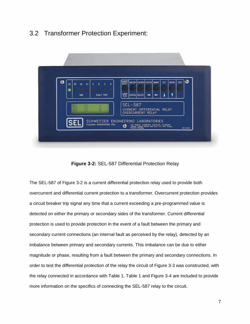
Figure 3-2: SEL-587 Differential Protection Relay
The SEL-587 of Figure 3-2 is a current differential protection relay used to provide both
overcurrent and differential current protection to a transformer. Overcurrent protection provides
a circuit breaker trip signal any time that a current exceeding a pre-programmed value is
detected on either the primary or secondary sides of the transformer. Current differential
protection is used to provide protection in the event of a fault between the primary and
secondary current connections (an internal fault as perceived by the relay), detected by an
imbalance between primary and secondary currents. This imbalance can be due to either
magnitude or phase, resulting from a fault between the primary and secondary connections. In
order to test the differential protection of the relay the circuit of Figure 3-3 was constructed, with
the relay connected in accordance with Table 1. Table 1 and Figure 3-4 are included to provide
more information on the specifics of connecting the SEL-587 relay to the circuit.

8
Figure 3-3: Transformer Protection Circuit
Figure 3-4: SEL-587 Rear Panel Diagram [1]

9
Table 1: SEL 587 Rear Panel Circuit Connections
Signal SEL Connection Circuit Connection
Primary Current In (A) IAW 1 (101) CB 1 A Out
Primary Current Out (A) IAW 1 (102) XFRMR A In
Secondary Current In (A) IAW 2 (107) CB 2 A Out
Secondary Current Out (A) IAW 2 (108) 400 Ω Resistor A
Primary Current In (B) IBW 1 (103) CB 1 B Out
Primary Current Out (B) IBW 1 (104) XFRMR B In
Secondary Current In (B) IBW 2 (109) CB 2 B Out
Secondary Current Out (B) IBW 2 (110) 400 Ω Resistor B
Primary Current In (C) ICW 1 (105) CB 1 C Out
Primary Current Out (C) ICW 1 (106) XFRMR C In
Secondary Current In (C) ICW 2 (111) CB 2 C Out
Secondary Current Out (C) ICW 2 (112) 400 Ω Resistor C
CB 1 Trip (High) OUT 1 (203) CB 1 Trip (High)
CB 1 Trip (Low) OUT 1 (204) CB 1 Trip (Low)
CB 2 Trip (High) OUT 2 (205) CB 2 Trip (High)
CB 2 Trip (Low) OUT 2 (206) CB 2 Trip (Low)
The circuit breakers used contain both normal and fault connections, enabling the option of
placing faults on the low voltage side of the transformer. The faults placed on the circuit breaker
consist of single-line/double-line to ground faults (SLG and DLG) as well as line-to-line faults
(LL) and three phase faults (3Θ). In order to ensure proper operation, the relay must be
programmed with normal operating conditions as well as the logic to enable specific tripping
10
conditions. Refer to the note on circuit breakers for specifics on how different fault conditions
were connected.
The 587 relay is programmed with the SEL proprietary program “AcSELerator Quickset”, which
is used for the full suite of SEL protective relays. In order to provide protection for both
overcurrent and differential fault conditions, the relay was programmed in accordance with
Appendix A and the SEL-587 User Manual [1]. One exception was made to the
recommendations of the User Manual in regards to the setting for the O87P relay sensitivity.
The User Manual recommends setting this value to 0.3 which is significantly sensitive enough
for Utility purposes. However, this experiment required voltages and currents much lower than
what is encountered in industrial applications and as such the sensitivity was insufficient to allow
the relay to trip. After much experimentation it was discovered that reducing the O87P setting to
0.1 allowed the relay to operate in coordination with the current and voltage values used in the
experiment.
Overcurrent protection was chosen to prevent damage to transformer windings due to excessive
current excursions, and is implemented by programming a current threshold into the relay which
sets the limit for what currents are allowable. If currents in excess of limits are detected, a trip
signal is sent to the high-voltage side circuit breaker, opening the circuit. Differential protection
is used to detect a fault within the zone of protection of the relay and was chosen both to protect
the transformer and to provide the ability of inserting a fault in the low-voltage circuit breaker.
The operation of current differential protection is shown below in Figure 3-5.

11
Figure 3-5: Current Differential Protection [4]
Under normal operation the currents detected by the primary and secondary current
transformers are equal in magnitude and direction, ensuring that the current travels directly
through the circuit formed by the current transformers (CT). When a fault is inserted in this
experiment the current conducted by the secondary CT is reversed, causing current to be
conducted through the operating coil of the faulted phase. The energization of the operating coil
informs the relay of the existence of a fault, resulting in a trip signal being provided to the circuit
breaker and clearing the fault by securing power.

12
3.3 Transmission Line Protection:
Figure 3-6: SEL-311L Line Protection Relay
The above relay, the SEL-311L, was used to protect the transmission line in this project. Used
correctly, the SEL-311L is a very powerful piece of equipment, allowing fault sensing via
current differential, overcurrent, and communications such as pilot protection. The scope of our
experimentation covered differential protection and overcurrent protection. The transmission line
that was protected by our SEL-311L was a circuit consisting of 20Ω of resistance and 200mH of
inductance, feeding a 10Ω load radially. To simulate a fault along a transmission line (the most
common fault detected by a 311L), the electrical “center” of the line was connected to the Circuit
Breaker fault box as described before, in various configurations including L-L, SLG, DLG, and
3ϕ faults. The 311L was able to detect and clear such faults reliably. The circuit used can be seen
in Figure 3-7.

13
Figure 3-7: Transmission Line Protection Circuit
Figure 3-8 and Table 2 display the exact connections used in the circuit, as well as a schematic
of the rear panel of the SEL-311L.
Figure 3-8: SEL-311L Rear Panel [7]
In addition to the following connections, the relay was also connected to another SEL-311L via
fiber optic cable to allow communication fault sensing. Originally, both relays were used to
sense a fault using POTT (pilot) protection, but the SEL-311L would consistently trip for current
differential instead of the desired communications fault event.

14
Table 2: SEL 311L Rear Panel Connections
Signal SEL Connection Circuit Connection
Phase A Current In IA (Z01) CB 2 A Out
Phase A Current Out IA (Z02) XMSSN Line 10 Ω A
Phase B Current In IB (Z03) CB 2 B Out
Phase B Current Out IB (Z04) XMSSN Line 10 Ω B
Phase C Current In IC (Z05) CB 2 C Out
Phase C Current Out IC (Z06) XMSSN Line 10 Ω C
Breaker Trip (High) OUT 101 (A01) CB 2 Trip (High)
Breaker Trip (Low) OUT 101 (A02) CB 2 Trip (Low)
Phase A Voltage VA (Z09) CB 2 A Out
Phase B Voltage VB (Z10) CB 2 B Out
Phase C Voltage VC (Z11) CB 2 C Out
Neutral Voltage N (Z12) Circuit Ground
In addition to operating upon the principle of differential current established in the previous
section, the SEL-311L would trip for faults of an overcurrent or impedance nature. These have
to do with zone impedance protection, which is implemented as a Mho relay. Below can be seen
an example zone protection schematic in Figure 3-9 [5] as well as a graph displaying a mho
relay characteristic impedance circle in Figure 3-10 [6].

15
Figure 3-9: Zone Protection Example [5]
Figure 3-10: Mho Impedance Relay Circle Example [6]
The impedance relay operation of the SEL-311L allows for selective tripping of the transmission
line, so that the relay won’t trip for every fault that occurs, only those which it needs to be aware
of. Zones further from the relay take a longer time to trip, but require less current (and thus a
larger impedance is allowable).

16
3.4 Motor Protection:
Figure 3-11: SEL-710 Motor Protection Relay
Motor protection was accomplished by use of the SEL-710 motor protection relay, pictured
above. This relay protects a motor from any potentially damaging faults, such as undervoltage,
overvoltage, current imbalance, locked rotor, thermal overload, and overcurrent. The circuit
which can be seen below is fairly simple, 240V 3 phase supplied to current limiting resistors
followed by the SEL-710 and circuit breaker. For our purposes, we faulted the induction motor
before the actual induction motor for overcurrent, and removed a single line connection for the
current imbalance. Removing a line was done by connecting a single phase of the line through
the fault connection of the circuit breaker box, and when removing the line, the switch was
flipped from the ‘fault’ position to the ‘normal’ unfaulted position - removing the phase of the line,
and causing a current imbalance. Thermal overload occurred when too much current was
sensed to be flowing to the motor which would likely result in overheating. A thermal lockout
disables the supervisor’s control and trips the motor offline for several minutes, in order to cool
the motor down. Locked rotor can cause currents in excess of 3-6x the rated full load current
draw, and causes the primary protection of the SEL-710 to trip: Overcurrent protection. The
circuit seen below in Figure 3-12 is used due to simplicity in testing, as well as in maintaining a
high enough voltage for the induction motor.

17
Figure 3-12: Motor Protection Circuit

18
Figure 3-13: SEL-710 Rear Panel [8]
Due to the motor not having sufficient voltage to clear an undervoltage trip condition upon
startup, the 710 will continuously send a trip signal to the circuit breaker box until voltage has
been received on the lower end of the breaker. This prevents the breaker from being closed to
the normal position, and requires the user to short the trip terminals of the breaker to allow for
19
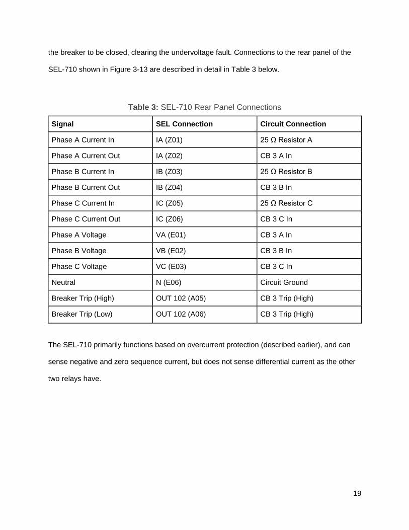
the breaker to be closed, clearing the undervoltage fault. Connections to the rear panel of the
SEL-710 shown in Figure 3-13 are described in detail in Table 3 below.
Table 3: SEL-710 Rear Panel Connections
Signal SEL Connection Circuit Connection
Phase A Current In IA (Z01) 25 Ω Resistor A
Phase A Current Out IA (Z02) CB 3 A In
Phase B Current In IB (Z03) 25 Ω Resistor B
Phase B Current Out IB (Z04) CB 3 B In
Phase C Current In IC (Z05) 25 Ω Resistor C
Phase C Current Out IC (Z06) CB 3 C In
Phase A Voltage VA (E01) CB 3 A In
Phase B Voltage VB (E02) CB 3 B In
Phase C Voltage VC (E03) CB 3 C In
Neutral N (E06) Circuit Ground
Breaker Trip (High) OUT 102 (A05) CB 3 Trip (High)
Breaker Trip (Low) OUT 102 (A06) CB 3 Trip (High)
The SEL-710 primarily functions based on overcurrent protection (described earlier), and can
sense negative and zero sequence current, but does not sense differential current as the other
two relays have.

20
3.5 System Integration and Protection:
Transmission Line
3φ 240V Source
25 Resistors
SEL-587 Primary
3φ 1:1 Transformer
CB 1
SEL-587 Secondary
CB 2
SEL-311L
SEL-710
10 Resistors
100mH Inductor
CB 3
3φ Induction Motor
100mH Inductor
10 Resistors
10 Load
X
X
X
X = Fault Location
SEL-587 Protective Relay
Figure 3-14: Overall System Integration
Once each relay had been tested satisfactorily and the connections and programming were
understood, the system setup of Figure 15 above was constructed. The initial design called for
the transmission line supplying the motor, but due to the large voltage drops of the transmission
line there was an insufficient voltage supplied to the motor. Instead it was decided to power both
the transmission line and the motor through the same bus to ensure sufficient terminal voltage
on the motor. Additionally, the supply voltage applied to the transformer was increased from
208V to 240V and the turns ratio of the transformer was increased to 1:1 in order to further
increase the voltage supplied to the motor. Further concerns with this design focus on the fact
that the SEL-587 can no longer provide differential protection with only one side of the
transformer being supplied with bus voltage, due to the fact that the differential relay is not able
to be energized in this configuration. Since the differential element was not able to be tested,
CB 2 was used to insert faults into the center of the transmission line as opposed to faulting the
secondary side of the transformer. Due to increasing the supply voltage and adding the motor to
the system configuration, there will be larger currents conducted through the transformer and as
such the sensitivity setting of the relay (O87P) needed to be increased to the manufacturer
recommendation of 0.3 (as opposed to 0.1 as used previously when testing the transformer
individually). Tables 4-6 are included below to provide clarification on the connections of the

21
individual relays, which are similar to the individual component experiments but have slight
differences.
Table 4: SEL 587 Connections
Signal SEL Connection Circuit Connection
Primary Current In (A) IAW 1 (101) 25 Ω Resistor A
Primary Current Out (A) IAW 1 (102) CB 1 A In
Secondary Current In (A) IAW 2 (107) Transformer A Out
Secondary Current Out (A) IAW 2 (108) CB 2 A In
Primary Current In (B) IBW 1 (103) 25 Ω Resistor B
Primary Current Out (B) IBW 1 (104) CB 1 B In
Secondary Current In (B) IBW 2 (109) Transformer B Out
Secondary Current Out (B) IBW 2 (110) CB 2 B In
Primary Current In (C) ICW 1 (105) 25 Ω Resistor C
Primary Current Out (C) ICW 1 (106) CB 1 C In
Secondary Current In (C) ICW 2 (111) Transformer C Out
Secondary Current Out (C) ICW 2 (112) CB 2 C In
Breaker Trip (High) OUT 1 (203) CB 1 Trip (High)
Breaker Trip (Low) OUT 1 (204) CB 1 Trip (Low)

22
Table 5: SEL 311L Connections
Signal SEL Connection Circuit Connection
Phase A Current In IA (Z01) CB 2 A Out
Phase A Current Out IA (Z02) XMSSN Line 10 Ω A
Phase B Current In IB (Z03) CB 2 B Out
Phase B Current Out IB (Z04) XMSSN Line 10 Ω B
Phase C Current In IC (Z05) CB 2 C Out
Phase C Current Out IC (Z06) XMSSN Line 10 Ω C
Breaker Trip (High) OUT 101 (A01) CB 2 Trip (High)
Breaker Trip (Low) OUT 101 (A02) CB 2 Trip (Low)
Phase A Voltage VA (Z09) Transformer A Out
Phase B Voltage VB (Z10) Transformer B Out
Phase C Voltage VC (Z11) Transformer C Out
Neutral Voltage N (Z12) Circuit Ground

23
Table 6: SEL 710 Connections
Signal SEL Connection Circuit Connection
Phase A Current In IA (Z01) CB 2 A Out
Phase A Current Out IA (Z02) CB 3 A In
Phase B Current In IB (Z03) CB 2 B Out
Phase B Current Out IB (Z04) CB 3 B In
Phase C Current In IC (Z05) CB 2 C Out
Phase C Current Out IC (Z06) CB 3 C In
Phase A Voltage VA (E01) CB 3 A In
Phase B Voltage VB (E02) CB 3 B In
Phase C Voltage VC (E03) CB 3 C In
Neutral N (E06) Circuit Ground
Breaker Trip (High) OUT 102 (A05) CB 3 Trip (High)
Breaker Trip (Low) OUT 102 (A06) CB 3 Trip (High)
Initially the transformer relay caused CB 1 to trip open on overcurrent as soon as CB 3 shut,
powering on the motor. It was determined that this overcurrent trip was in response to the inrush
current of the motor and decreasing the sensitivity setting of the SEL-587 allowed the motor to
be operated. This initial issue also served to verify that the overcurrent protection of the
transformer was indeed working as designed with the system connected. Once the system was
successfully powered on, testing commenced by repeating fault tests for the motor and
transmission lines. In order to provide maximum reliability, it was desired that a motor fault
should only trip the motor circuit breaker (CB 3) and a transmission line fault should only result
in the transmission line circuit breaker (CB 2) opening. This design simulates a real-world
system in which selective-tripping is employed to reduce the amount of equipment affected by a

24
fault in the system. When the transmission line was faulted, both the transformer and motor
relays continued normal operation while the SEL-311L caused CB 2 to trip open. Conversely
when the motor was loaded with sufficient torque to cause a locked rotor condition or one of the
three supply phases was removed, the SEL-710 caused CB 3 to trip open while the transformer
and transmission lines continued normal operation.

25
3.6 Analysis of Transformer Protection Experiments/Results:
3.6.1 Three-Phase Fault Trip
Once the transformer circuit was constructed the protection settings were tested by inserting
faults into the low-voltage circuit breaker (CB 2 in Figure 3-3). The faults included single-phase
to ground, line-line faults and three-phase faults to ground. Proper response to the fault was
exhibited by both circuit breakers tripping open and the energizing of the associated LEDs on
the front of the relay. The anticipated indicator LEDs include the 87 LED, indicating that the
differential relay element triggered the protection action, as well as the associated phase(s) that
were faulted. The relay was tested in all possible transformer configurations (Δ-Δ, Δ-Y, Y-Δ and
Y-Y), which requires slight adjustment of the relay programming for each iteration. It should be
noted that while current transformers (CTs) were not used in this experiment, the relay CT
setting must be set in combination with transformer configuration in accordance with Table 7
below.

26
Table 7: Transformer and CT Coordination [1]
Since the secondary current of the transformer was faulted in all of these experiments, the event
files resulted from faults are almost identical to one another when examining the primary
currents. The event file demonstrates normal circuit operation until the fault is detected, at which
point the circuit breaker opens and breaks the path for current conduction, resulting in all
currents dropping to zero. Analyzing a bolted three phase fault, it can be seen from Figures 3-15
and 3-16 below that approximately 5 cycles (.08 sec) after the fault is inserted, the high-voltage
breaker has opened, clearing the fault. The insertion of this fault eliminates the 400Ω load from
the circuit, resulting in increased currents for all three phases. Contrary to what is seen in a
ground fault, there is no zero sequence current detected by the relay. Another indication this
fault involves all three phases is the relative magnitude of the 3 phase currents (approximately
equal) while maintaining 120 degree phase difference between the phases. Comparing the
primary currents to the secondary currents, there is a 180 degree phase difference which is

27
indicative that the current in the primary is conducted in the opposite direction as what is
perceived by the secondary connection. This agrees with what is expected in an internal fault,
as seen by the SEL-587 relay, resulting in an activation of the 87 (differential) trip relay.
Figure 3-15: Relay Phasor Diagram at 3.75 Cycles (Bolted Three Phase Fault)

28
Figure 3-16: Time Response of Relay (Bolted Three Phase Fault)

29
3.6.2 Line-Line Fault Trip
Similarly, a Line-Line fault (connecting phases A and B) results in breaker operation within 5
cycles. Breaker operation time is a function on the relay settings and may be reduced (to
provide additional protection) or increased (for demonstration purposes) by adjusting the
settings. Examining Figures 3-17 and 3-18 below, it can be seen that phase A and B currents
are 180 degrees out of phase with an equal magnitude (indicative of L-L fault) and there is no
zero sequence current detected, ruling out a grounding fault. As opposed to the fault above, the
phase C primary current is much smaller in magnitude than either phase A or B (almost zero).
Comparing the phases of primary and secondary currents, phases A and B have 180 degree
phase differences between the primary and secondary currents, while phase C has an
approximately 45 degree difference. Further supporting that phase C is not faulted in this
situation.

30
Figure 3-17: Phasor Diagram (Line to Line Fault)
Figure 3-18: Line-Line Fault Phase A-B

31
3.7 Analysis of Motor Protection Experiments/Results:
3.7.1 Current Imbalance Trip
The analysis of the SEL-710 began with faulting the motor via an imbalanced current.
This was achieved as mentioned before, by removing a phase of the line. This resulted
in a current of 0 amps for the line removed while the voltage remained the same. The
relay took 5 seconds to trip on the fault after sensing it. The breaker then took an
additional several seconds to open the circuit. The currents and voltages can be seen
below in Figure 3-19.
Figure 3-19: Current Imbalance (Lost Phase) Trip Event
The phasor diagram of the fault can be seen below in Figure 3-20. It can be seen clearly
that IA is zero, where IB and IC are 180 degrees out of phase and opposite, clearly
denoting a lost phase. There is no zero sequence or ground current, as expected.

32
Figure 3-20: Current Imbalance (Lost Phase) Phasor Diagram
33
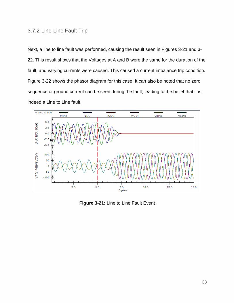
3.7.2 Line-Line Fault Trip
Next, a line to line fault was performed, causing the result seen in Figures 3-21 and 3-
22. This result shows that the Voltages at A and B were the same for the duration of the
fault, and varying currents were caused. This caused a current imbalance trip condition.
Figure 3-22 shows the phasor diagram for this case. It can also be noted that no zero
sequence or ground current can be seen during the fault, leading to the belief that it is
indeed a Line to Line fault.
Figure 3-21: Line to Line Fault Event

34
Figure 3-22: Line to Line Fault Phasor Diagram
It is clear from the phasor diagram that VA and VB are the same, as the currents all vary
in an unbalanced case.

35
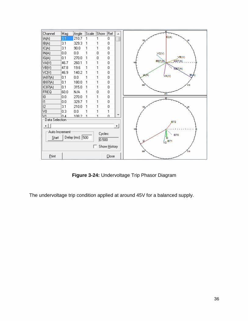
3.6.3 Undervoltage Condition Trip
The next event was an undervoltage trip shown in Figure 3-23. This event was caused
by using a series 3-phase variac within the system, and lowering the voltage by
increasing the impedance of the variac.
Figure 3-23: Undervoltage Trip Event
This event was caused due to a balanced undervoltage on the line feeding the motor.
Like the other cases, the fault was sensed within 5 cycles, and tripped shortly thereafter.
The phasor diagram can be seen in Figure 3-24.
36
Figure 3-24: Undervoltage Trip Phasor Diagram
The undervoltage trip condition applied at around 45V for a balanced supply.

37
3.8 Analysis of Transmission Line Protection
Experiments/Results:
3.8.1 Line-Line Fault Trip
After the transmission circuit construction had been completed, the circuit was put
through several fault tests to determine the competency of the impedance and
differential tripping.
Figure 3-25: Impedance Trip (Line to Line) Event

38
Figure 3-26: Impedance Trip (Line to Line) Phasor Diagram
Figures 3-25 and 3-26 show the event recorded for an impedance Zone 1 detected
fault. Negative sequence current was detected in this fault, without any zero sequence
current, implying a line to line fault, as we would expect based on the test.

39
3.8.2 Double-Line-Ground Fault Trip
Figure 3-27 and 3-28 show the case for a DLG fault, complete with zero sequence
current.
Figure 3-27: DLG Fault Event
Figures 3-25 and 3-27 both show a response time of 4 seconds before the relay
operated to clear the fault. Figure 3-27 and 3-28 also clearly show a DLG fault, as
Figure 3-28 shows zero sequence current and phasors in line of what one would expect
with a A-C-G fault.

40
Figure 3-28: DLG Event Phasor Diagram

41
4 Conclusion & Future Project Suggestions:
4.1 Conclusion
Through the classes and labs offered through the Electrical Engineering curriculum offered at
Cal Poly students are introduced to the principles of protection and the operation of
electromechanical relays. These relays use the principles of electromagnetism in coordination
with mechanical settings to determine what currents will cause a circuit breaker (both
instantaneously and over time). While the implementation of these protective actions is
performed differently in a microprocessor-based relay (through programmed logic and electrical
signals), the method used to determine these settings is the same. Fortunately,
electromechanical relays (while not cutting-edge technology) are still very prevalent in industry,
and any exposure to this equipment is beneficial to a student with a desire to entire the power
distribution and protection industries. Unfortunately, the curriculum does not have any time set
aside to address microprocessor-based relays which introduce another level of complexity to
the work performed by Protection Engineers. This newer technology introduces a greater
reliance on computer programming skills as well as the integration of communication principles
and signal processing. What this experiment has done is to provide students with real-world
experience designing protection for equipment that a new Protection Engineer is going to be
dealing with by using the type of protection equipment that will be available.
Another major lesson learned from this experiment is that there is a definite need to pursue and
understand various protection schemes when determining how to protect a system. An
excessive reliance upon any given scheme leaves a system open to different vulnerabilities. It
has been reiterated in the SEL equipment manuals as well as instructors that Power Distribution

42
and Protection is not just a science, it is also an art. There is no “best” approach for any given
system, there are as many different approaches as there are Engineers examining the system.
The idea is that an Engineer needs to use their experience to design a system that provides
adequate protection (against any kind of foreseeable fault) using as many different methods as
possible to ensure reliability in the event of a failed protection method. It is the responsibility of
every Engineer to expose themselves to as many different and new ideas as possible in order to
maximize the design options open for a given project. This principle drives Engineers to
continuously better themselves and the product of their labors.

43
4.2 Future Project Suggestions:
With the successful implementation of protection schemes for transformers, transmission lines
and motors, the next step was system integration. With the three relays coordinated to provide
overlapping protection to the entire system, the next logical step is to incorporate a master
control unit enabling remote operation of all relays and associated circuit breakers. Schweitzer
Engineering Laboratories manufactures the SEL-2032 Communications Processor for
integration and coordination of multiple microprocessor units. The SEL-2032 unit is designed
with the integration of an entire substation of equipment, which includes transformers, motors,
transmission lines and has the capability to support a much larger system than the equipment in
university labs configure. Additionally, the SEL-2032 has the ability to automatically configure
itself depending on the SEL products that it is connected to.Future projects can focus on SEL-
2032 units that have previously been donated to the school and determining the optimum
communication medium (ethernet or fiber optics) and the best terminal program to interface the
unit with a computer. Schweitzer Engineering Laboratory has also recently announced the
donation of much more recent SEL equipment to the school in the upcoming years, and future
students can and should work to replicate this experiment with newer equipment. The principles
of operation should remain the same while the implementation using newer equipment should
be more streamlined and even more relevant for students entering into the power industry.

44
Appendix A: Programming Relays with AcSELerator
Quickset
Talk about how to use the AcSELerator program and specifics for the individual relays.
AcSELerator Quickset is available from the SEL website for free after creating a user account.
Once the program is downloaded and installed, communication with the relays MUST be
conducted with the 9 pin cable, and it is recommended to use the school computers. There is a
USB cable that should work, but there are communication issues between the relay and the
computer using that cable, and as such should not be used. In order to connect to the relay, the
communication parameters must be calibrated by opening the Communications tab and
selecting “Parameters”. A menu like Figure A-1 below should open:

45
Figure A-1: Communication Parameters Menu
The Relay will be communicating via the serial port, which must be configured as shown (with
the exception that the SEL-710 relay uses a Baud Rate of 9600 as opposed to 2400, which is
used by both the SEL-587 and SEL-311L). The Passwords for the specific relays are contained
in Table 8.
46
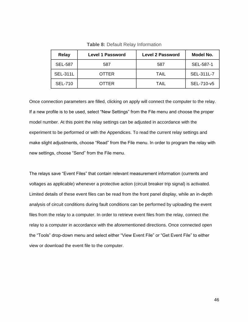
Table 8: Default Relay Information
Relay Level 1 Password Level 2 Password Model No.
SEL-587 587 587 SEL-587-1
SEL-311L OTTER TAIL SEL-311L-7
SEL-710 OTTER TAIL SEL-710-v5
Once connection parameters are filled, clicking on apply will connect the computer to the relay.
If a new profile is to be used, select “New Settings” from the File menu and choose the proper
model number. At this point the relay settings can be adjusted in accordance with the
experiment to be performed or with the Appendices. To read the current relay settings and
make slight adjustments, choose “Read” from the File menu. In order to program the relay with
new settings, choose “Send” from the File menu.
The relays save “Event Files” that contain relevant measurement information (currents and
voltages as applicable) whenever a protective action (circuit breaker trip signal) is activated.
Limited details of these event files can be read from the front panel display, while an in-depth
analysis of circuit conditions during fault conditions can be performed by uploading the event
files from the relay to a computer. In order to retrieve event files from the relay, connect the
relay to a computer in accordance with the aforementioned directions. Once connected open
the “Tools” drop-down menu and select either “View Event File” or “Get Event File” to either
view or download the event file to the computer.

47
Appendix B: SEL-587 Programming
General Data ->
MVA = 9.0;
VWG1 = 208.00;
VWG2 = 104.00;
TRCON = YY; *Dependant upon transformer configuration
CTCON = YY; *Dependant upon transformer configuration
CTR1 = 1;
CTR2 = 2;
Differential Elements ->
O87P = 0.1;
U87P = 6.4;
Logic ->
X =87R+87U;
Y = NA;
MTU1 = 87R + 87U;
MTU2 = 87R + 87U;
OUT1 = !TRIP;
Group Setting Range Default
Value Value Delta Description Hidden
1 RID Range = ASCII
string with a
maximum length of
12.
XFMR 1 XFMR 1 False RID Relay Identifier (12
characters) False
1 TID Range = ASCII
string with a
maximum length of
12.
STATION
A STATION A False TID Terminal Identifier (12
characters) False
1 MVA Range = 0.2 to
5000.0, OFF 50 9.0 True MVA Maximum Power
Transformer Capacity
(MVA)
False
1 VWDG1 Range = 1.00 to
1000.00 138.00 208.00 True VWDG1 Winding 1 Line to
Line Voltage (kV) False
1 VWDG2 Range = 1.00 to
1000.00 69.00 104.00 True VWDG2 Winding 2 Line to
Line Voltage (kV) False
1 TRCON Select: YY, YDAC,
YDAB, DACDAC,
DABDAB, DABY,
DACY, OTHER
DABY YY True TRCON Xfmr False
1 CTCON Select: DACDAC,
DABDAB, YY YY DACDAC True CTCON CT Connection False
1 RZS Select: Y, N N N False RZS Remove I0 from Y
Connection
False

48
Compensation
1 CTR1 Range = 1 to 50000 50 1 True CTR1 Winding 1 CT Ratio False
1 CTR2 Range = 1 to 50000 100 1 True CTR2 Winding 2 CT Ratio False
1 DATC Range = 5 to 255,
OFF 15 15 False DATC Demand Ammeter
Time Constant (minutes) False
1 PDEM Range = 0.5 to 16.0 5.3 5.3 False PDEM Phase Demand
Ammeter Threshold (A) False
1 QDEM Range = 0.5 to 16.0 1 1.0 True QDEM Neg.-Seq. Demand
Ammeter Threshold (A) False
1 NDEM Range = 0.5 to 16.0 1 1.0 True NDEM Residual Demand
Ammeter Threshold (A) True
1 TAP1 Range = 0.50 to
160.00 43.27 43.27 False TAP1 Winding 1 Current
Tap False
1 TAP2 Range = 0.50 to
160.00 86.54 86.54 False TAP2 Winding 2 Current
Tap False
1 IN1 Select: NA, 52A1,
!52A1, TCEN, TCBL 52A1 NA True IN1 Input 1 False
1 IN2 Select: NA, 52A2,
!52A2, TCEN, TCBL 52A2 NA True IN2 Input 2 False
1 O87P Range = 0.1 to 1.0 0.3 0.1 True O87P Operating Current
PU (TAP) False
1 SLP1 Range = 5 to 100 40 40 False SLP1 Restraint Slope 1
(%) False
1 SLP2 Range = 25 to 200,
OFF OFF OFF False SLP2 Restraint Slope 2
(%) False
1 IRS1 Range = 1.0 to 16.0 3.0 3.0 False IRS1 Restraint Current
Slope 1 Limit (TAP) True
1 U87P Range = 1.0 to 16.0 10.0 1.8 True U87P Inst Unrestrained
Current PU (TAP) False
1 PCT2 Range = 5 to 100,
OFF 15 15 False PCT2 2nd Harmonic
Blocking Percentage (%) False
1 PCT4 Range = 5 to 100,
OFF 15 15 False PCT4 4th Harmonic
Blocking Percentage (%) False
1 PCT5 Range = 5 to 100,
OFF 35 35 False PCT5 5th Harmonic
Blocking Percentage (%) False
1 TH5 Range = 0.1 to 3.2 0.3 0.3 False TH5 5th Harmonic
Threshold (TAP) False
1 TH5D Range = 0.000 to
8000.000 30 30.000 True TH5D 5th Harmonic Alarm
TDPU (cyc) False
1 DCRB Select: Y, N Y Y False DCRB DC Ratio Blocking False
1 HRSTR Select: Y, N Y Y False HRSTR Harmonic
Restraint False
1 IHBL Select: Y, N Y Y False IHBL Independent
Harmonic Blocking True
1 50P1P Range = 0.5 to 80.0,
OFF 52.3 52.3 False 50P1P Phase Def.-Time
O/C PU False
1 50P1D Range = 0.00 to
16000.00 5 5.00 True 50P1D Phase Def.-Time
O/C Delay (cyc) False
1 50P1TC Select: Y, N N N False 50P1TC Phase Def.-Time True

49
O/C External TC
1 50P1H Range = 0.5 to 80.0,
OFF 73.2 73.2 False 50P1H Phase Inst O/C PU
(A) False
1 50P1HC Select: Y, N N N False 50P1HC Phase Inst. O/C
External TC True
1 51P1P Range = 0.5 to 16.0,
OFF 6.3 6.3 False 51P1P Phase Inv.-Time
O/C PU (A) False
1 51P1C Select: U1, U2, U3,
U4, C1, C2, C3, C4 U2 U2 False 51P1C Phase Inv.-Time
O/C Curve False
1 51P1TD Range = 0.50 to
15.00 3.80 3.80 False 51P1TD Phase Inv.-Time
O/C Time-Dial False
1 51P1RS Select: Y, N Y Y False 51P1RS Phase Inv.-Time
O/C EM Reset False
1 51P1TC Select: Y, N N N False 51P1TC Phase Inv.-Time
O/C External True
1 50Q1P Range = 0.5 to 80.0,
OFF 78.4 78.4 False 50Q1P Neg.-Seq. Def.-
Time O/C PU (A) False
1 50Q1D Range = 0.50 to
16000.00 5 5.00 True 50Q1D Neg.-Seq. Def.-
Time O/C Delay (cyc) False
1 50Q1TC Select: Y, N N N False 50Q1TC Neg.-Seq. Def.-
Time O/C External TC True
1 51Q1P Range = 0.5 to 16.0,
OFF 10 10.0 True 51Q1P Neg.-Seq. Inv.-
Time O/C PU (A) False
1 51Q1C Select: U1, U2, U3,
U4, C1, C2, C3, C4 U4 U4 False 51Q1C Neg.-Seq. Inv.-
Time O/C Curve False
1 51Q1TD Range = 0.50 to
15.00 6.60 6.60 False 51Q1TD Neg.-Seq. Inv.-
Time O/C Time-Dial False
1 51Q1RS Select: Y, N Y Y False 51Q1RS Neg.-Seq. Inv.-
Time O/C EM Reset False
1 51Q1TC Select: Y, N N N False 51Q1TC Neg.-Seq. Inv.-
Time O/C External TC True
1 50N1P Range = 0.5 to 80.0,
OFF OFF OFF False 50N1P Residual Def.-Time
O/C PU (A) True
1 50N1D Range = 0.00 to
16000.00 16000 16000.00 True 50N1D Residual Def.-Time
O/C Delay (cyc) True
1 50N1TC Select: Y, N N N False 50N1TC Residual Def.-
Time O/C External TC True
1 50N1H Range = 0.5 to 80.0,
OFF OFF OFF False 50N1H Residual Inst O/C
PU (A) True
1 50N1HC Select: Y, N N N False 50N1HC Residual Inst O/C
External TC True
1 51N1P Range = 0.5 to 16.0,
OFF OFF OFF False 51N1P Residual Inv.-Time
O/C PU (A) True
1 51N1C Select: U1, U2, U3,
U4, C1, C2, C3, C4 U4 U4 False 51N1C Residual Inv.-Time
O/C Curve True
1 51N1TD Range = 0.50 to
15.00 15.00 15.00 False 51N1TD Residual Inv.-
Time O/C Time-Dial True
1 51N1RS Select: Y, N Y Y False 51N1RS Residual Inv.-
Time O/C EM Reset True

50
1 51N1TC Select: Y, N N N False 51N1TC Residual Inv.-
Time O/C External TC True
1 50P2P Range = 0.5 to 80.0,
OFF 52.3 52.3 False 50P2P Phase Def.-Time
O/C PU False
1 50P2D Range = 0.00 to
16000.00 5 5.00 True 50P2D Phase Def.-Time
O/C Delay (cyc) False
1 50P2TC Select: Y, N N N False 50P2TC Phase Def.-Time
O/C External TC True
1 50P2H Range = 0.5 to 80.0,
OFF OFF OFF False 50P2H Phase Inst O/C PU
(A) False
1 50P2HC Select: Y, N N N False 50P2HC Phase Inst. O/C
External TC True
1 51P2P Range = 0.5 to 16.0,
OFF 6.3 6.3 False 51P2P Phase Inv.-Time
O/C PU (A) False
1 51P2C Select: U1, U2, U3,
U4, C1, C2, C3, C4 U2 U2 False 51P2C Phase Inv.-Time
O/C Curve False
1 51P2TD Range = 0.50 to
15.00 2.50 2.50 False 51P2TD Phase Inv.-Time
O/C Time-Dial False
1 51P2RS Select: Y, N Y Y False 51P2RS Phase Inv.-Time
O/C EM Reset False
1 51P2TC Select: Y, N N N False 51P2TC Phase Inv.-Time
O/C External True
1 50Q2P Range = 0.5 to 80.0,
OFF OFF OFF False 50Q2P Neg.-Seq. Def.-
Time O/C PU (A) False
1 50Q2D Range = 0.50 to
16000.00 16000 16000.00 True 50Q2D Neg.-Seq. Def.-
Time O/C Delay (cyc) True
1 50Q2TC Select: Y, N N N False 50Q2TC Neg.-Seq. Def.-
Time O/C External TC True
1 51Q2P Range = 0.5 to 16.0,
OFF OFF OFF False 51Q2P Neg.-Seq. Inv.-
Time O/C PU (A) False
1 51Q2C Select: U1, U2, U3,
U4, C1, C2, C3, C4 U4 U4 False 51Q2C Neg.-Seq. Inv.-
Time O/C Curve True
1 51Q2TD Range = 0.50 to
15.00 15.00 15.00 False 51Q2TD Neg.-Seq. Inv.-
Time O/C Time-Dial True
1 51Q2RS Select: Y, N Y Y False 51Q2RS Neg.-Seq. Inv.-
Time O/C EM Reset True
1 51Q2TC Select: Y, N N N False 51Q2TC Neg.-Seq. Inv.-
Time O/C External TC True
1 50N2P Range = 0.5 to 80.0,
OFF 52.3 OFF True 50N2P Residual Def.-Time
O/C PU (A) True
1 50N2D Range = 0.00 to
16000.00 5 5.00 True 50N2D Residual Def.-Time
O/C Delay (cyc) True
1 50N2TC Select: Y, N N N False 50N2TC Residual Def.-
Time O/C External TC True
1 50N2H Range = 0.5 to 80.0,
OFF OFF OFF False 50N2H Residual Inst O/C
PU (A) True
1 50N2HC Select: Y, N N N False 50N2HC Residual Inst O/C
External TC True
1 51N2P Range = 0.5 to 16.0, 3 OFF True 51N2P Residual Inv.-Time True

51
OFF O/C PU (A)
1 51N2C Select: U1, U2, U3,
U4, C1, C2, C3, C4 U4 U4 False 51N2C Residual Inv.-Time
O/C Curve True
1 51N2TD Range = 0.50 to
15.00 12.40 12.40 False 51N2TD Residual Inv.-
Time O/C Time-Dial True
1 51N2RS Select: Y, N Y Y False 51N2RS Residual Inv.-
Time O/C EM Reset True
1 51N2TC Select: Y, N N N False 51N2TC Residual Inv.-
Time O/C External TC True
1 LTRP Select: Y, N, NL, 1-3 N N False LTRP Latch Trips False
1 TDURD Range = 0.000 to
2000.000 9 9.000 True TDURD Minimum Trip
Duration Time Delay (cyc) False
1 TXPU Range = 0.000 to
8000.000 0 0.000 True TXPU Timer X Pickup
Delay (cyc) False
1 TXDO Range = 0.000 to
8000.000 0 0.000 True TXDO Timer X Dropout
Delay (cyc) False
1 TYPU Range = 0.000 to
8000.000 0 0.000 True TYPU Timer Y Pickup
Delay (cyc) False
1 TYDO Range = 0.000 to
8000.000 0 0.000 True TYDO Timer Y Dropout
Delay (cyc) False
1 NFREQ Select: 50, 60 60 60 False NFREQ Nominal
Frequency (Hz) False
1 PHROT Select: ABC, ACB ABC ACB True PHROT Phase Rotation False
L X Valid range =
Boolean equation
using word bit
elements and the
legal operators: ! / \
( ) * +
NA !87R+!87U True X (SELogic Equation) False
L Y Valid range =
Boolean equation
using word bit
elements and the
legal operators: ! / \
( ) * +
NA NA False Y (SELogic Equation) False
L MTU1 Valid range =
Boolean equation
using word bit
elements and the
legal operators: ! / \
( ) * +
50P1T +
51P1T +
50Q1T +
51Q1T +
OC1
87R+87U True MTU1 (SELogic Equation) False
L MTU2 Valid range =
Boolean equation
using word bit
elements and the
legal operators: ! / \
( ) * +
50P2T +
51P2T +
50N2T +
51N2T +
OC2
87R+87U True MTU2 (SELogic Equation) False
L MTU3 Valid range =
Boolean equation
using word bit
elements and the
legal operators: ! / \
( ) * +
87R + 87U 87R+87U True MTU3 (SELogic Equation) False

52
L MER Valid range =
Boolean equation
using word bit
elements and the
legal operators: ! / \
( ) * +
87R + 87U
+ 50P1T +
51P1T +
50Q1T +
51Q1T +
50P2T +
51P2T +
51N2T
87R+87U+50P1T+5
1P1T+50Q1T+51Q1
T+50P2T+51P2T+51
N2T
True MER (SELogic Equation) False
L OUT1 Valid range =
Boolean equation
using word bit
elements and the
legal operators: ! / \
( ) * +
TRP1 !TRP1 True OUT1 (SELogic Equation) False
L OUT2 Valid range =
Boolean equation
using word bit
elements and the
legal operators: ! / \
( ) * +
TRP2 !TRP2 True OUT2 (SELogic Equation) False
L OUT3 Valid range =
Boolean equation
using word bit
elements and the
legal operators: ! / \
( ) * +
TRP3 TRP3 False OUT3 (SELogic Equation) False
L OUT4 Valid range =
Boolean equation
using word bit
elements and the
legal operators: ! / \
( ) * +
87R + 87U
+ 50P1T +
51P1T +
50Q1T +
51Q1T +
50P2T +
51P2T +
51N2T
87R+87U+50P1T+5
1P1T+50Q1T+51Q1
T+50P2T+51P2T+51
N2T
True OUT4 (SELogic Equation) False
P PROTOC
OL Select: SEL, LMD SEL SEL False PROTOCOL Port Protocol False
P PREFIX Select: @, #, $, %,
&& @ @ False PREFIX LMD Prefix True
P ADDRES
S Range = 1 to 99 1 1 False ADDRESS LMD Address True
P SETTLE
_TIME Range = 0 to 30 0 0 False SETTLE_TIME LMD
Settling Time (sec) True
P SPEED Select: 300, 1200,
2400, 4800, 9600,
19200, 38400
2400 2400 False SPEED Baud Rate (bps) False
P DATA_BI
TS Select: 7, 8 8 8 False DATA_BITS Number Data
Bits False
P PARITY Select: O, E, N N N False PARITY Parity False
P STOP Select: 1, 2 1 1 False STOP Stop Bits (bits) False
P TIMEOU
T Range = 0 to 30 5 5 False TIMEOUT Timeout (min) False
P AUTO Select: Y, N Y Y False AUTO Auto Message
Output False

53
P RTS_CT
S Select: Y, N N N False RTS_CTS Enable
RTS/CTS Handshaking False
P FAST_O
P Select: Y, N N N False FAST_OP Enable Fast
Operate False

54
Appendix C: SEL-311L Settings
Group 1 -> Set 1 -> General
CTR = 1;
Group 1 -> Set 1 -> Backup Protection and Line Parameters
PTR = 1;
Z1Mag = 78.0;
Z1Ang = 75.0;
Z0Mag = 78.0;
Z0Ang = 75.0;
LL = 100;
Group 1 -> Set 1 -> Phase Distance
E21P = 1;
Z1P = 60;
Group 1 -> Set 1 -> Ground Distance
E21MG =1;
Z1MG = 60;
Group 1 -> Logic 1 -> Trip/Comm - Assisted Logic
TR = M1P+Z1G;
Group 1 -> Logic 1 -> Output Contact
Out101 = !(M1P+Z1G)
Global -> General
NFREQ = 60;
PHROT = ACB;

55

56

57

58

59

60

61
Appendix D: SEL-710 Settings
Global -> General ->
APP = Full;
PHROT = ACB;
FNOM = 60;
Group 1 -> Set 1 -> Main ->
CTR1 = 1;
FLA1 = 1.4;
E2SPEED = N;
CTRN = 1;
PTR = 1;
VNOM = 208;
DELTA_Y = WYE;
Group 1 -> Set 1 -> Thermal Overload Elements->
E49MOTOR = Y;
FLS = OFF;
SF = 1.15;
LRA1 = 3.00;
LRTHOT1 = 2.00;
RTC1 = AUTO;
Group 1 -> Set 1 -> Overcurrent Elements -> Phase Overcurrent
50P1P = 4.50;
50P1D = 0.00;
Group 1 -> Set 1 -> Overcurrent Elements -> Negative Sequence Overcurrent
50Q1P = 1.40;
50Q1D = 0.1;
Group 1 -> Set 1 -> Over/Under Voltage ->Undervoltage Elements
27P1P = 0.7;
27P1D = 3.0;
Group 1 -> Set 1 -> Logic 1 -> Slot A
OUT101FS = N;
OUT102FS = Y;
OUT102 = TRIP;
OUT103FS = Y;
OUT102 = NOT TRIP;

62

63

64

65

66

67
References:
[1] Schweitzer Engineering Laboratories, SEL-587-1 Relay Current Differential Relay
Overcurrent Relay Instruction Manual, Pullman, Washington: Schweitzer Engineering
Laboratories 1995-2015.
[2] O. Corulli, “Motor Protection Lab Experiment Using SEL-710”, Dept. Elect. Eng.,
California Polytechnic State Univ., San Luis Obispo, Senior Project Report, Jun. 2013.
[3] B. Van Loon, “SEL-311L Overreaching Impedance Pilot Protection Laboratory”, Dept.
Elect. Eng., California Polytechnic State Univ., San Luis Obispo, Senior Project Report, Jun.
2013.
[4] Electrical4U.com “Differential Protection of Transformer Differential Relays”
Electrical4U.com. [Online]. Available: http://www.electrical4u.com/differential-protection- of-
transformer-differential-relays/ [Accessed: May, 18, 2016]
[5] M. ZELLAGUI and A. CHAGHI, Principal operation of MHO distance relay. [Online]
Available: http://lejpt.academicdirect.org/A21/get_htm.php?htm=001_014.
[6] M. ZELLAGUI and A. CHAGHI, Settings zones of MHO distance relay. [Online]
Available:http://lejpt.academicdirect.org/A21/get_htm.php?htm=001_014.
[7] Schweitzer Engineering Laboratories, SEL-311L-6 Relay Protection and Automation
System Instruction Manual, Pullman, Washington: Schweitzer Engineering Laboratories 2001-
2015.
[8] Schweitzer Engineering Laboratories, SEL-710 Motor Protection Relay Instruction
Manual, Pullman, Washington: Schweitzer Engineering Laboratories 2006-2015.