Embed Size (px)
Citation preview
Integration of Multi-Cell MIMO Transmission
and Relaying in Mobile Communication
Systems
Peter Rost, Student Member, IEEE, Gerhard Fettweis, IEEE
Fellow, and J. Nicholas Laneman, Senior Member, IEEE
Abstract
In this paper, relaying and multi-cell MIMO transmission are investigated as possibilities to improve
the resource reuse and to more flexibly organize cellular networks. Our analysis focuses on approaches
for future cellular systems, which jointly exploit relaying and multi-cell MIMO transmission. We evaluate
these approaches using the system level model of the European research project WINNER and analyze
the achievable throughput under practical constraints. Finally, we provide an analysis of the cost-benefit
tradeoff in relay-assisted systems. It turns out to be a reasonable choice for the downlink if multiple base
stations cooperatively serve relays and relays coordinate their resources to serve users. The backhaul
requirements between multiple sites can be reduced by only considering a cooperation of base-stations
co-located at the same site, which still provides almost the same gains as multi-cell MIMO transmission
from different sites.
Index Terms
Relaying, multiple antenna systems, cellular networks, half-duplex constraint, cost-benefit tradeoff,
wide-area coverage scenario, Manhattan-area high-throughput scenario
Manuscript submitted September 22, 2009. G. Fettweis and P. Rost are with the Vodafone Chair for Mobile Communications
Systems, Technische Universitat Dresden (TUD), Dresden, Germany (Email: {fettweis, rost}@ifn.et.tu-dresden.de). J. N.
Laneman is with the University of Notre Dame (IN), USA (Email: [email protected])
September 22, 2009 DRAFT
SUBMITTED TO IEEE JOURNAL ON SELECTED AREAS IN COMMUNICATIONS 1
Integration of Multi-Cell MIMO Transmission
and Relaying in Mobile Communication
Systems
I. INTRODUCTION
A. Motivation of our work
In current and future mobile communication systems both the required data rates and the
number of mobile subscribers increase exponentially. Since the capacity per cell is limited, the
spatial reuse of available resources must increase. Hence, cells become smaller, which is coupled
with higher carrier frequencies offering higher path-loss and therefore better separation of cells.
Since each cell is served by its own (logical) radio access point (RAP), 4G systems demand
a large number of RAPs, which can be economically satisfied by additional, cheaply deployed
relay nodes.
Among the most serious challenges in current and future mobile communication systems is
the mitigation or avoidance of inter-cell interference. Future mobile communication systems are
likely to use multi-cell MIMO approaches in which multiple base stations cooperatively serve
user terminals using techniques introduced in the context of the MIMO broadcast channel [1], [2].
Furthermore, additional relay nodes will help to provide high data rates in otherwise shadowed
areas as well as to further improve the channel conditions at cell borders [3].
Consider a mobile communication system in which multiple base station antenna arrays
at the same cell site (typically three) serve adjacent sectors within the cell site. These base
station antenna arrays are often mounted on a single tower and can share the same radio and
processing hardware. Therefore multi-cell MIMO transmission can be easily implemented. By
contrast, multi-cell MIMO transmission from base stations at different sites requires a substantial
backhaul in order to exchange channel state information (CSI) and data. In either scenario, these
regions could be better served by additional relay nodes, which implement interference mitigation
techniques and improve the spatial reuse. These observations motivate the study of multi-cell
MIMO and relaying integrated in one system architecture, which is the focus of this paper.
September 22, 2009 DRAFT

SUBMITTED TO IEEE JOURNAL ON SELECTED AREAS IN COMMUNICATIONS 2
B. Outline and Contribution
We explore system architectures based upon the transmission schemes introduced in [4], where
we employed a link-level analysis of the relay-assisted interference channel. These schemes are
able to combine the benefits of multi-cell MIMO transmission and relaying in one integrated
system architecture. We apply them to the system model of a next-generation mobile communi-
cation network and compare the performance of a conventional system, a system using multi-cell
MIMO only, a system using relaying only, and a system in which both multi-cell MIMO and
relaying are integrated. This comparison is done for two different propagation scenarios, which
demonstrate the ability of the integrated system approach to counteract inter-cell interference
and to improve indoor coverage. Our analysis pays special attention to possibilities for reducing
complexity and signaling overhead in 4G networks in order to improve the cost-benefit tradeoff.
The remainder of the paper is organized as follows. Section II introduces the system model
and reviews a proposed architecture for a next generation mobile communication system. Section
III discusses the system and protocol design, and summarizes the approaches for the mobile
communication system. Section IV then analyzes these approaches using various constraints and
figures of merit. Finally, Section V concludes the paper with further comments on implications
for future mobile communication systems.
II. SYSTEM MODEL
A. Propagation scenarios
This paper considers the proposed system architecture of the European research project WIN-
NER [6] for a next-generation mobile communication system. WINNER considers three propa-
gation scenarios: indoor, wide-area (macro-cellular), and Manhattan street-grid (micro-cellular)
[7]1. In this paper, we focus on the two scenarios wide-area and Manhattan street-grid because
both scenarios allow for an analysis of the two most challenging problems in 4G networks:
inter-cell interference and indoor coverage. Wide-area corresponds to a hexagonal cell-structure,
which is illustrated in Fig. 1(a). Each site (indicated with ”BS”) is equipped with three base
station antenna arrays serving three adjacent sectors (with main lobe directions indicated by
arrows) and two stationary relays per sector (indicated by triangles). Sites are uniformly placed,
1All referred WINNER documents are publicly available on http://www.ist-winner.org
September 22, 2009 DRAFT
SUBMITTED TO IEEE JOURNAL ON SELECTED AREAS IN COMMUNICATIONS 3
BS
BS
BS
BS
BS
BS
BS
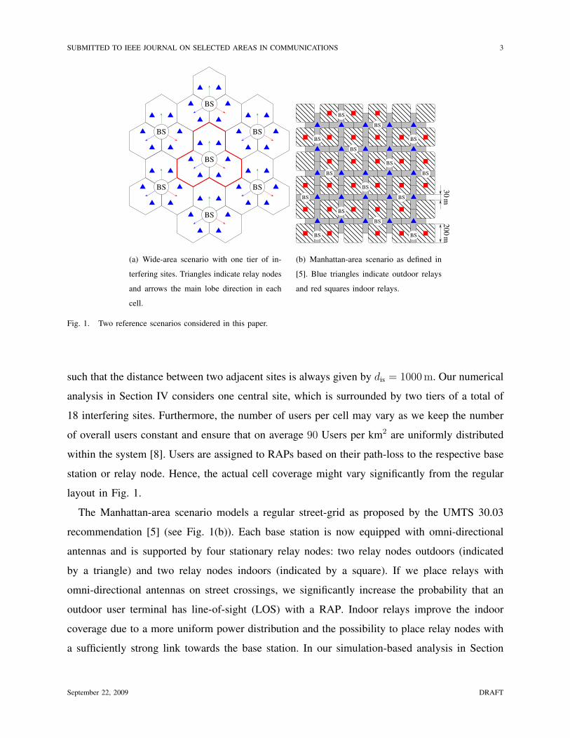
(a) Wide-area scenario with one tier of in-
terfering sites. Triangles indicate relay nodes
and arrows the main lobe direction in each
cell.
20
0m
30
m
BS
BS
BS
BS
BS
BS
BS
BSBS
BS
BS
BS
BS
BS
BS
(b) Manhattan-area scenario as defined in
[5]. Blue triangles indicate outdoor relays
and red squares indoor relays.
Fig. 1. Two reference scenarios considered in this paper.
such that the distance between two adjacent sites is always given by dis = 1000 m. Our numerical
analysis in Section IV considers one central site, which is surrounded by two tiers of a total of
18 interfering sites. Furthermore, the number of users per cell may vary as we keep the number
of overall users constant and ensure that on average 90 Users per km2 are uniformly distributed
within the system [8]. Users are assigned to RAPs based on their path-loss to the respective base
station or relay node. Hence, the actual cell coverage might vary significantly from the regular
layout in Fig. 1.
The Manhattan-area scenario models a regular street-grid as proposed by the UMTS 30.03
recommendation [5] (see Fig. 1(b)). Each base station is now equipped with omni-directional
antennas and is supported by four stationary relay nodes: two relay nodes outdoors (indicated
by a triangle) and two relay nodes indoors (indicated by a square). If we place relays with
omni-directional antennas on street crossings, we significantly increase the probability that an
outdoor user terminal has line-of-sight (LOS) with a RAP. Indoor relays improve the indoor
coverage due to a more uniform power distribution and the possibility to place relay nodes with
a sufficiently strong link towards the base station. In our simulation-based analysis in Section
September 22, 2009 DRAFT

SUBMITTED TO IEEE JOURNAL ON SELECTED AREAS IN COMMUNICATIONS 4
Manhattan-area Wide-area
BS to RN B5c B5a
BS to indoor UT B4
BS to outdoor UT B1 C2
RN to indoor UT B4
RN to outdoor UT B1 C2
indoor RN to indoor UT A1
TABLE I
USED CHANNEL MODELS, WHICH ARE DEFINED IN [9].
IV, we use overall 44 cells but only consider the results for the three inner cells. Compared to
the wide-area scenario, we assume a higher user density with 250 Users per km2 placed both
on streets and within buildings [8].
The WINNER system offers a variety of channel models suitable for each scenario. Each
consists of a model for the probability that a strong LOS link exists, the path-loss model, and
the power delay profile, which models the small scale fading assuming each tap is Gaussian
distributed. We further assume block fading in which each channel realization is independently
generated. Table I lists all channel models, which are used in our paper’s numerical analysis.
Each channel model is described in detail in [9].
B. Air interface
In our model, we apply Orthogonal Frequency Division Multiplexing (OFDM) [11], [12] at
a carrier frequency fc = 3.95 GHz with bandwidth Bw = 100 MHz and Nc = 2048 subcarriers.
Since signal delays are not considered, we choose time division duplexing (TDD) for both the
wide-area and the Manhattan-area scenario. All further air interface parameters are listed in Table
II and described in further detail in [7].
We further assume Gaussian alphabets, perfect rate adaptation, and infinite blocklengths in
order to use the relevant capacity expressions [4] and to have an upper bound on the achievable
rates. Throughout the following discussion we assume perfect channel estimation and that the
system is perfectly synchronized. Of course, especially in systems supporting relay nodes,
synchronization and channel estimation are significant challenges but these issues are outside
September 22, 2009 DRAFT
SUBMITTED TO IEEE JOURNAL ON SELECTED AREAS IN COMMUNICATIONS 5
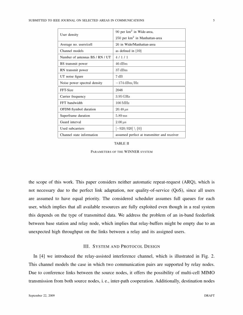
User density90 per km2 in Wide-area,
250 per km2 in Manhattan-area
Average no. users/cell 26 in Wide/Manhattan-area
Channel models as defined in [10]
Number of antennas BS / RN / UT 4 / 1 / 1
BS transmit power 46 dBm
RN transmit power 37 dBm
UT noise figure 7 dB
Noise power spectral density !174 dBm/Hz
FFT-Size 2048
Carrier frequency 3.95 GHz
FFT bandwidth 100 MHz
OFDM-Symbol duration 20.48 µs
Superframe duration 5.89 ms
Guard interval 2.00 µs
Used subcarriers [!920; 920] \ {0}
Channel state information assumed perfect at transmitter and receiver
TABLE II
PARAMETERS OF THE WINNER SYSTEM
the scope of this work. This paper considers neither automatic repeat-request (ARQ), which is
not necessary due to the perfect link adaptation, nor quality-of-service (QoS), since all users
are assumed to have equal priority. The considered scheduler assumes full queues for each
user, which implies that all available resources are fully exploited even though in a real system
this depends on the type of transmitted data. We address the problem of an in-band feederlink
between base station and relay node, which implies that relay-buffers might be empty due to an
unexpected high throughput on the links between a relay and its assigned users.
III. SYSTEM AND PROTOCOL DESIGN
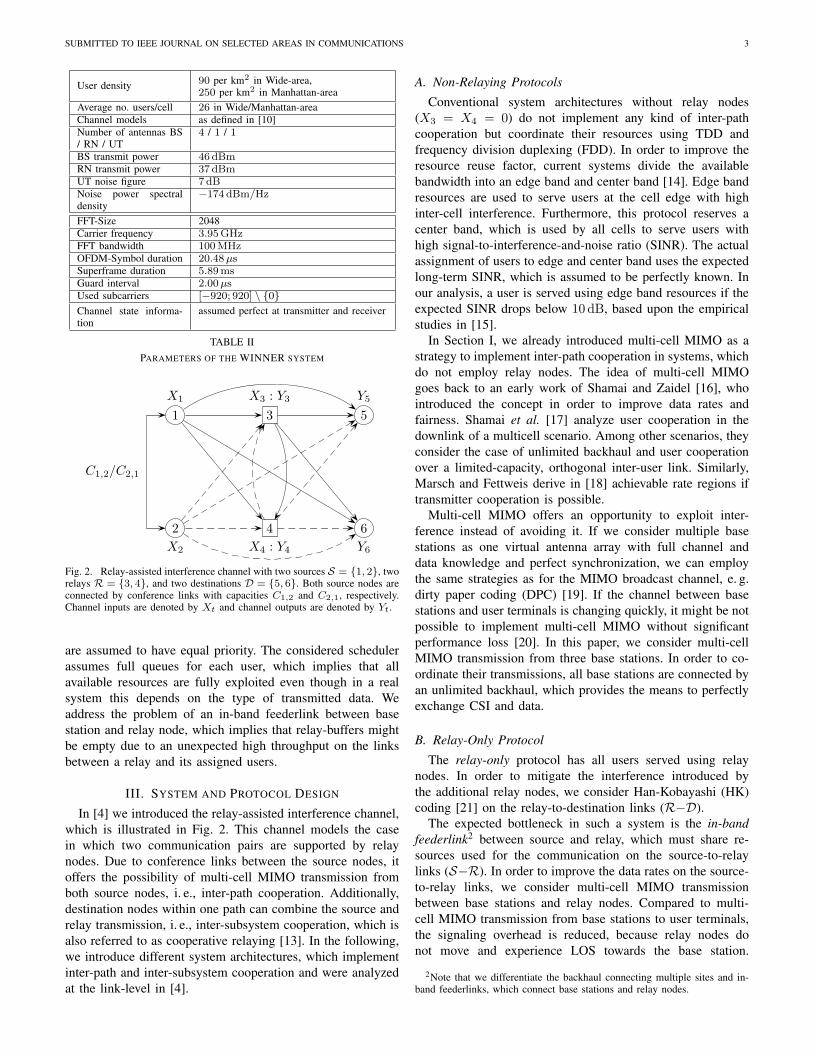
In [4] we introduced the relay-assisted interference channel, which is illustrated in Fig. 2.
This channel models the case in which two communication pairs are supported by relay nodes.
Due to conference links between the source nodes, it offers the possibility of multi-cell MIMO
transmission from both source nodes, i. e., inter-path cooperation. Additionally, destination nodes
September 22, 2009 DRAFT

SUBMITTED TO IEEE JOURNAL ON SELECTED AREAS IN COMMUNICATIONS 6
1X1
3X3 : Y3
5Y5
2X2
4X4 : Y4
6Y6
C1,2/C2,1
Fig. 2. Relay-assisted interference channel with two sources S = {1, 2}, two relays R = {3, 4}, and two destinations
D = {5, 6}. Both source nodes are connected by conference links with capacities C1,2 and C2,1, respectively. Channel inputs
are denoted by Xt and channel outputs are denoted by Yt.
within one path can combine the source and relay transmission, i. e., inter-subsystem cooperation,
which is also referred to as cooperative relaying [13]. In the following, we introduce different
system architectures, which implement inter-path and inter-subsystem cooperation and were
analyzed at the link-level in [4].
A. Non-Relaying Protocols
Conventional system architectures without relay nodes (X3 = X4 = 0) do not implement any
kind of inter-path cooperation but coordinate their resources using TDD and frequency division
duplexing (FDD). In order to improve the resource reuse factor, current systems divide the
available bandwidth into an edge band and center band [14]. Edge band resources are used to
serve users at the cell edge with high inter-cell interference. Furthermore, this protocol reserves
a center band, which is used by all cells to serve users with high signal-to-interference-and-
noise ratio (SINR). The actual assignment of users to edge and center band uses the expected
long-term SINR, which is assumed to be perfectly known. In our analysis, a user is served using
edge band resources if the expected SINR drops below 10 dB, based upon the empirical studies
in [15].
In Section I, we already introduced multi-cell MIMO as a strategy to implement inter-path
cooperation in systems, which do not employ relay nodes. The idea of multi-cell MIMO goes
back to an early work of Shamai and Zaidel [16], who introduced the concept in order to
improve data rates and fairness. Shamai et al. [17] analyze user cooperation in the downlink
September 22, 2009 DRAFT

SUBMITTED TO IEEE JOURNAL ON SELECTED AREAS IN COMMUNICATIONS 7
of a multicell scenario. Among other scenarios, they consider the case of unlimited backhaul
and user cooperation over a limited-capacity, orthogonal inter-user link. Similarly, Marsch and
Fettweis derive in [18] achievable rate regions if transmitter cooperation is possible.
Multi-cell MIMO offers an opportunity to exploit interference instead of avoiding it. If we
consider multiple base stations as one virtual antenna array with full channel and data knowledge
and perfect synchronization, we can employ the same strategies as for the MIMO broadcast
channel, e. g. dirty paper coding (DPC) [19]. If the channel between base stations and user
terminals is changing quickly, it might be not possible to implement multi-cell MIMO without
significant performance loss [20]. In this paper, we consider multi-cell MIMO transmission from
three base stations. In order to coordinate their transmissions, all base stations are connected by
an unlimited backhaul, which provides the means to perfectly exchange CSI and data.
B. Relay-Only Protocol
The relay-only protocol has all users served using relay nodes. In order to mitigate the
interference introduced by the additional relay nodes, we consider Han-Kobayashi (HK) coding
[21] on the relay-to-destination links (R!D).
The expected bottleneck in such a system is the in-band feederlink2 between source and relay,
which must share resources used for the communication on the source-to-relay links (S!R).
In order to improve the data rates on the source-to-relay links, we consider multi-cell MIMO
transmission between base stations and relay nodes. Compared to multi-cell MIMO transmission
from base stations to user terminals, the signaling overhead is reduced, because relay nodes do not
move and experience LOS towards the base station. Furthermore, the user grouping is simplified
as only a small number of fixed relay nodes is considered.
C. An integrated approach
Link-level results in [4] suggest that the previous protocol might not be able to provide the
required performance figures for users close to the base station. Hence, we consider a mixed
protocol in which users are either served using multi-cell MIMO transmission or relaying. Based
2Note that we differentiate the backhaul connecting multiple sites and in-band feederlinks, which connect base stations and
relay nodes.
September 22, 2009 DRAFT
SUBMITTED TO IEEE JOURNAL ON SELECTED AREAS IN COMMUNICATIONS 8
Inter-Path
Coordination CooperationIn
ter-
Subsy
stem
Coord
inat
ion
• TDD or HK on both hops
• Direct transmission
• DPC on S " R or S " D
• HK or TDD on R "D
Cooper
atio
n
• Cooperative relaying
• Source and relay jointly em-
ploy DPC
• All nodes form one virtual an-
tenna array
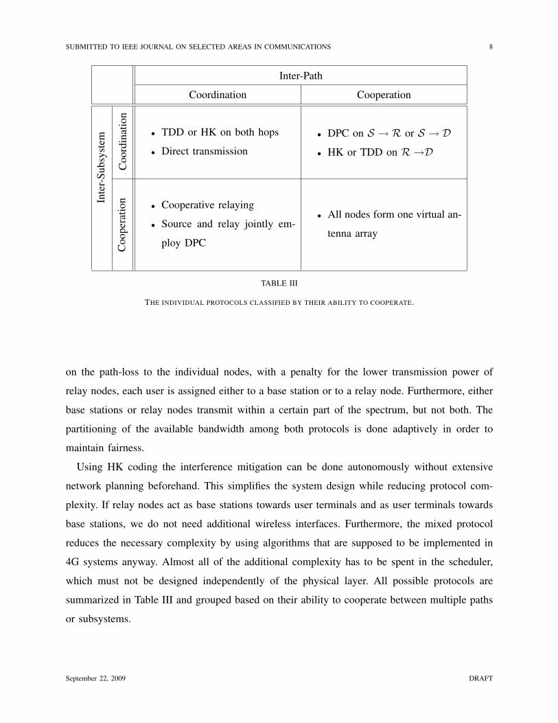
TABLE III
THE INDIVIDUAL PROTOCOLS CLASSIFIED BY THEIR ABILITY TO COOPERATE.
on the path-loss to the individual nodes, with a penalty for the lower transmission power of
relay nodes, each user is assigned either to a base station or to a relay node. Furthermore, either
base stations or relay nodes transmit within a certain part of the spectrum, but not both. The
partitioning of the available bandwidth among both protocols is done adaptively in order to
maintain fairness.
Using HK coding the interference mitigation can be done autonomously without extensive
network planning beforehand. This simplifies the system design while reducing protocol com-
plexity. If relay nodes act as base stations towards user terminals and as user terminals towards
base stations, we do not need additional wireless interfaces. Furthermore, the mixed protocol
reduces the necessary complexity by using algorithms that are supposed to be implemented in
4G systems anyway. Almost all of the additional complexity has to be spent in the scheduler,
which must not be designed independently of the physical layer. All possible protocols are
summarized in Table III and grouped based on their ability to cooperate between multiple paths
or subsystems.
September 22, 2009 DRAFT
SUBMITTED TO IEEE JOURNAL ON SELECTED AREAS IN COMMUNICATIONS 9
D. Simplifications
In [4] DPC and HK coding have been used. Both techniques require an extensive optimization
in order to determine the correct precoding matrices (DPC) or power levels (HK coding). If
we apply both techniques to a mobile communication system, we would have to cope with a
significant computational overhead. Instead, we employ in our analysis Zero-Forcing DPC (ZF-
DPC) [22], instead of DPC with optimal precoding matrices, and Etkin-Tse-Wang (ETW) coding
[23], instead of HK coding over all possible power levels.
ZF-DPC uses the LQ-decomposition of the compound channel matrix and by precoding with
the unitary matrix Q, the effective channel becomes a triangular matrix. Then, DPC is applied
such that each user sees an interference-free link. Due to the large number of user terminals
and base stations, the user grouping is a computationally expensive problem. Hence, we apply a
simplified form of user grouping in which the assignment of user terminals to the individual base
stations is done based on the path-loss between base station and user terminal, i. e., each user
is assigned to the three base stations with the smallest path-loss towards this user. Furthermore,
the user grouping algorithm ensures that cooperating base stations serve those users with similar
preferences.
ETW coding is a particular form of HK coding in which the power levels can be determined
directly and which achieves rates within 1 bpcu of capacity. The optimal form of ETW coding
must determine the power levels for each subcarrier (or frame) individually. In order to reduce
the signaling overhead, we use the long-term SINR statistics (constant over both superframes)
instead of the fast-fading coefficients to determine the power levels. We further consider a two-
state ETW coding in which only the power levels 0 and 1 are allowed, i. e., a relay sends either
only a private message or a common message.
As with base stations, we use a simple form of user grouping for the assignment of users
to relay nodes. In order to ensure efficient interference mitigation each user is assigned to the
relay node with the smallest path-loss towards this user. The relay node with the second-smallest
path-loss towards this user is chosen and selected for the ETW coding. Based on this selection
another user with the same preferences is chosen and as many resources as possible are assigned
to this relay-user-pair.
September 22, 2009 DRAFT

SUBMITTED TO IEEE JOURNAL ON SELECTED AREAS IN COMMUNICATIONS 10
IV. NUMERICAL ANALYSIS
In order to evaluate the individual protocols and to understand their effects on the user
performance, we discuss in detail the following aspects of multi-cell MIMO transmission and
relaying:
• Ability of multi-cell MIMO transmission and relaying to counteract inter-cell interference
• Service improvements for indoor users
• Comparison of relaying and femto-cells
• Reduction of the required backhaul and signaling overhead
• Cost-benefit tradeoff of relay-based networks.
A. Simulation methodology
In order to evaluate the different protocols, we use a snapshot based, system-level simulation,
which does not explicitly model any user mobility. It rather models the effects of mobility on
the user’s channel instead of moving a particular user and tracking its performance. The latter
requires significantly more frames in order to reflect the low velocity of users. Therefore users are
randomly placed, and for each snapshot two superframes are simulated before the next snapshot
is drawn. For each frame within a superframe an independent instance of the small scale fading
process is drawn and the user scheduling is performed.
The overall area is partitioned into rectangles of equal size. In case of the wide-area scenario
they are of size 30 m # 30 m, and in case of the Manhattan-area scenario they are of size
10 m# 10 m. For each user the corresponding spatial block (x, y) is determined and the average
throughput !(x, y) = Et {!(x, y, t)} over all users, which have been placed in this block, is used
to determine the number of resources. Using a fair scheduler the number of resources assigned
to a user is proportional to !!1(x, y). The fact that we use the average throughput reflects that
we try to achieve a good tradeoff of high system throughput and fairness. In order to achieve
an improved fairness within the system, it would be more suitable to use the 5% quantile of
throughput !5%, with Pr {!(x, y, t) $ !5%} $ 5%. In this way, a user with a high throughput
variance gets even more resources in order to improve the 5% quantile of throughput at the
expense of other users’ performance.
September 22, 2009 DRAFT
SUBMITTED TO IEEE JOURNAL ON SELECTED AREAS IN COMMUNICATIONS 11
10-2
10-1
100
10-2 10-1 100 101 102
Throughput ! in MBit/s
Pr{!
(·,·
)$
!}
+
+
+
++ +
ConventionalMulti-Cell MIMO+2 Relays, relay-only2 Relays, mixed8 Relays, relay-only
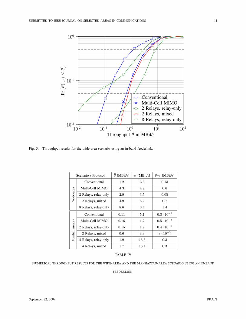
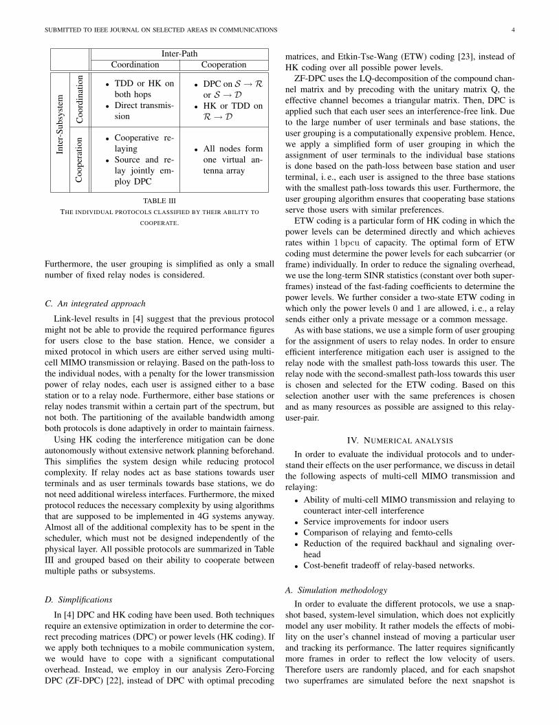
Fig. 3. Throughput results for the wide-area scenario using an in-band feederlink.
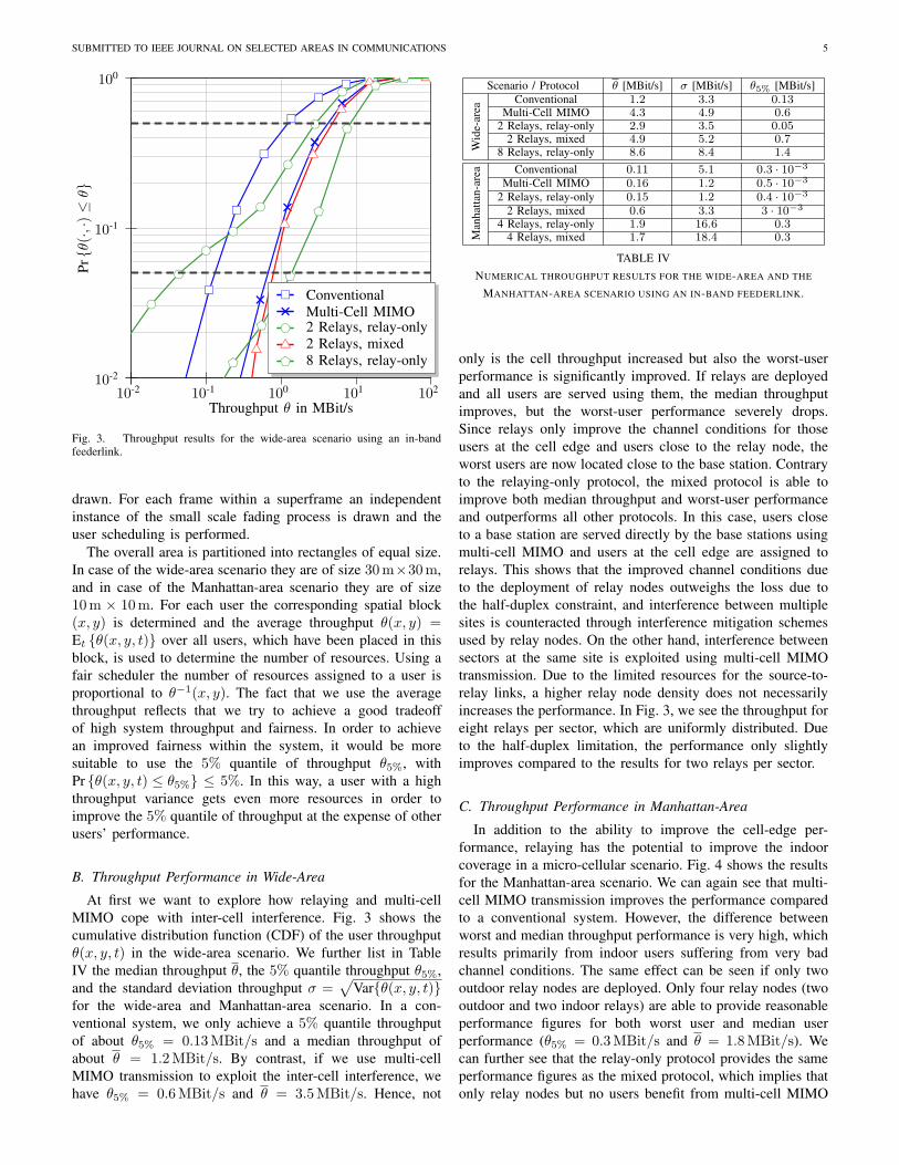
Scenario / Protocol ! [MBit/s] " [MBit/s] !5% [MBit/s]
Wid
e-ar
ea
Conventional 1.2 3.3 0.13
Multi-Cell MIMO 4.3 4.9 0.6
2 Relays, relay-only 2.9 3.5 0.05
2 Relays, mixed 4.9 5.2 0.7
8 Relays, relay-only 8.6 8.4 1.4
Man
hat
tan
-are
a
Conventional 0.11 5.1 0.3 · 10!3
Multi-Cell MIMO 0.16 1.2 0.5 · 10!3
2 Relays, relay-only 0.15 1.2 0.4 · 10!3
2 Relays, mixed 0.6 3.3 3 · 10!3
4 Relays, relay-only 1.9 16.6 0.3
4 Relays, mixed 1.7 18.4 0.3
TABLE IV
NUMERICAL THROUGHPUT RESULTS FOR THE WIDE-AREA AND THE MANHATTAN-AREA SCENARIO USING AN IN-BAND
FEEDERLINK.
September 22, 2009 DRAFT

SUBMITTED TO IEEE JOURNAL ON SELECTED AREAS IN COMMUNICATIONS 12
B. Throughput Performance in Wide-Area
At first we want to explore how relaying and multi-cell MIMO cope with inter-cell interference.
Fig. 3 shows the cumulative distribution function (CDF) of the user throughput !(x, y, t) in
the wide-area scenario. We further list in Table IV the median throughput !, the 5% quantile
throughput !5%, and the standard deviation throughput " =!
Var{!(x, y, t)} for the wide-
area and Manhattan-area scenario. In a conventional system, we only achieve a 5% quantile
throughput of about !5% = 0.13 MBit/s and a median throughput of about ! = 1.2 MBit/s. By
contrast, if we use multi-cell MIMO transmission to exploit the inter-cell interference, we have
!5% = 0.6 MBit/s and ! = 3.5 MBit/s. Hence, not only is the cell throughput increased but also
the worst-user performance is significantly improved. If relays are deployed and all users are
served using them, the median throughput improves, but the worst-user performance severely
drops. Since relays only improve the channel conditions for those users at the cell edge and
users close to the relay node, the worst users are now located close to the base station. Contrary
to the relaying-only protocol, the mixed protocol is able to improve both median throughput and
worst-user performance and outperforms all other protocols. In this case, users close to a base
station are served directly by the base stations using multi-cell MIMO and users at the cell edge
are assigned to relays. This shows that the improved channel conditions due to the deployment
of relay nodes outweighs the loss due to the half-duplex constraint, and interference between
multiple sites is counteracted through interference mitigation schemes used by relay nodes. On
the other hand, interference between sectors at the same site is exploited using multi-cell MIMO
transmission. Due to the limited resources for the source-to-relay links, a higher relay node
density does not necessarily increases the performance. In Fig. 3, we see the throughput for
eight relays per sector, which are uniformly distributed. Due to the half-duplex limitation, the
performance only slightly improves compared to the results for two relays per sector.
C. Throughput Performance in Manhattan-Area
In addition to the ability to improve the cell-edge performance, relaying has the potential
to improve the indoor coverage in a micro-cellular scenario. Fig. 4 shows the results for the
Manhattan-area scenario. We can again see that multi-cell MIMO transmission improves the
performance compared to a conventional system. However, the difference between worst and
median throughput performance is very high, which results primarily from indoor users suffering
September 22, 2009 DRAFT

SUBMITTED TO IEEE JOURNAL ON SELECTED AREAS IN COMMUNICATIONS 13
10-2
10-1
100
10-4 10-3 10-2 10-1 100 101
Throughput ! in MBit/s
Pr{!
(·,·
)$
!}
+
+
+
+
+
++
++ +
ConventionalMulti-Cell MIMO+2 Relays, relay-only2 Relays, mixed4 Relays, relay-only4 Relays, mixed
Fig. 4. CDF of the expected throughput in the Manhattan-area scenario. In the case only two relay nodes per sector are used,
both are deployed outdoors.
from very bad channel conditions. The same effect can be seen if only two outdoor relay
nodes are deployed. Only four relay nodes (two outdoor and two indoor relays) are able to
provide reasonable performance figures for both worst user and median user performance (!5% =
0.3 MBit/s and ! = 1.8 MBit/s). We can further see that the relay-only protocol provides the
same performance figures as the mixed protocol, which implies that only relay nodes but no
users benefit from multi-cell MIMO transmission in this micro-cellular scenario.
D. Femto-Cells vs. Relaying
Currently, an alternative way of improving indoor coverage and data rate is to use femto-cells
[24], where small RAPs are home-deployed and connected to the available wired network, e. g.
DSL. This is similar to relaying even though relaying uses the same PHY interface for the
source-to-relay link instead of a wired network. Fig. 5 shows the results for the Manhattan-area
scenario and using femto-cells instead of relay nodes. In these results, we assume that femto-cells
do not require in-band feederlink resources and have access to a backhaul network, which always
provides the required data rates and does not limit the achievable rates on the relay-to-terminal
September 22, 2009 DRAFT

SUBMITTED TO IEEE JOURNAL ON SELECTED AREAS IN COMMUNICATIONS 14
10-2
10-1
100
10-4 10-3 10-2 10-1 100 101
Throughput ! in MBit/s
Pr{!
(·,·
)$
!}
+
+
+
+
+
++
++ +
ConventionalMulti-Cell MIMO+2 Relays, relay-only2 Relays, mixed4 Relays, relay-only4 Relays, mixed
Fig. 5. Results for out-of-band feeder deployed in Manhattan-area
links. Only the performance of four relay nodes improves using femto-cells due to the fact that
femto-cell relay nodes can now additionally use those resources that would otherwise be used
to serve relays.
The necessity to connect the indoor RAP to the data network makes the deployment less
flexible and more expensive compared to relay nodes that use in-band feederlinks. Furthermore,
it requires the availability of a high-speed network and it only works indoors where such a
network is available. However, it also shows the flexibility of the relay concept because indoor
relay nodes could be equipped with an additional interface to the local wired network in order
to further improve the performance.
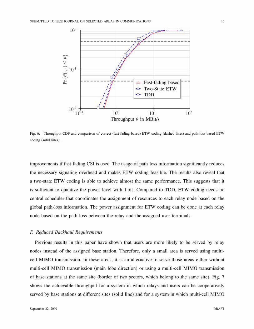
E. Reduced Signaling Overhead
Since relay nodes are not directly connected with each other, the exchanged signaling overhead
between them must be kept at a minimum. In Fig. 6, we compare the performance of optimal
ETW coding using fast-fading information, a two-state ETW coding with two possible power
assignments (either only private or common messages) and using the long-term SINR, and TDD
between relay nodes and user terminals. These results show that there are only minor performance
September 22, 2009 DRAFT
SUBMITTED TO IEEE JOURNAL ON SELECTED AREAS IN COMMUNICATIONS 15
10-2
10-1
100
10-1 100 101 102
Throughput ! in MBit/s
Pr{!
(·,·
)$
!}
Fast-fading based
Two-State ETWTDD
Fig. 6. Throughput-CDF and comparison of correct (fast-fading based) ETW coding (dashed lines) and path-loss-based ETW
coding (solid lines).
improvements if fast-fading CSI is used. The usage of path-loss information significantly reduces
the necessary signaling overhead and makes ETW coding feasible. The results also reveal that
a two-state ETW coding is able to achieve almost the same performance. This suggests that it
is sufficient to quantize the power level with 1 bit. Compared to TDD, ETW coding needs no
central scheduler that coordinates the assignment of resources to each relay node based on the
global path-loss information. The power assignment for ETW coding can be done at each relay
node based on the path-loss between the relay and the assigned user terminals.
F. Reduced Backhaul Requirements
Previous results in this paper have shown that users are more likely to be served by relay
nodes instead of the assigned base station. Therefore, only a small area is served using multi-
cell MIMO transmission. In these areas, it is an alternative to serve those areas either without
multi-cell MIMO transmission (main lobe direction) or using a multi-cell MIMO transmission
of base stations at the same site (border of two sectors, which belong to the same site). Fig. 7
shows the achievable throughput for a system in which relays and users can be cooperatively
served by base stations at different sites (solid line) and for a system in which multi-cell MIMO
September 22, 2009 DRAFT

SUBMITTED TO IEEE JOURNAL ON SELECTED AREAS IN COMMUNICATIONS 16
10-2
10-1
100
10-1 100 101 102
Throughput ! in MBit/s
Pr{!
(·,·
)$
!}
+
+
+
++ +
+
+
+
++ + +
ConventionalMulti-Cell MIMO+2 Relays, mixed
Fig. 7. Throughput CDF for a system with no inter-site cooperation. Relay nodes and users are cooperatively served by base
stations at the same site (solid line). For comparison the dashed line shows the performance if users are served cooperatively
by multiple sites.
transmission is limited to base stations at the same site (dashed lines). The former corresponds to
a system requiring substantial backhaul, which must support the required data rates to exchange
the additional CSI and message information. The latter corresponds to a conventional backhaul,
which is already used in current mobile communication systems. We can see that a system
architecture that only uses multi-cell MIMO transmission, suffers from a significant performance
loss if multi-cell MIMO transmission is limited to one site. On the other hand, if we use the
integrated approach with relaying and multi-cell MIMO transmission, the performance remains
almost unaffected. A system with multi-cell MIMO transmission only at one site requires less
backhaul and is more robust for scenarios with low coherence time/frequency.
G. Cost-benefit tradeoff
The previous discussion did not account for the additional deployment costs of relay nodes. In
order to normalize the results we have to keep constant either the costs for the system deployment
or the system performance. This paper uses the former way of normalizing the results. In the
following, we use CSite to denote the costs of a site and CRelay to denote the costs of a relay
September 22, 2009 DRAFT

SUBMITTED TO IEEE JOURNAL ON SELECTED AREAS IN COMMUNICATIONS 17
node, which includes hardware costs, rental costs, average costs for power supply as well as
backhaul costs (in case of a base station). Backhaul expenses depend on the BS density and
therefore affect the relative costs, which is not considered in this work. Furthermore, we use
#RN = CRelay/CSite to denote the costs of a relay node relative to a site. Table V gives an
example of the costs for a relay node and a site. For this particular example the relative relay
costs are given by #RN = 0.1, which is used in the remainder.
Item of Expenditure Relay Node Site (with 3 BS)
Hardware 10 kEUR 80 kEUR
Loan 3 years at 8 % 8 years at 8 %
Installation 5 kEUR 30 kEUR
Rental costs 100 EUR per month 1000 EUR per month
Energy costs
(at 10 Cent per kWh)
438 EUR p.a. (500W) 4.4 kEUR p.a. (5kW)
Life-Span 10a 10a
Cost-Ratio #RN = CRelay/CSite = 0.1
TABLE V
EXAMPLE FOR INITIAL AND OPERATING COSTS FOR A RELAY NODE AND SITE WITH THREE BASE STATIONS.
Under the assumption of a regular grid of sites and with NRelay relays deployed at each site,
the inter-site distance in a relay-based deployment is given by
dis (#) = dis
!
1 + #RNNRelay, (1)
in order to normalize the deployment costs (dis is the inter-site distance in a system without
relays).
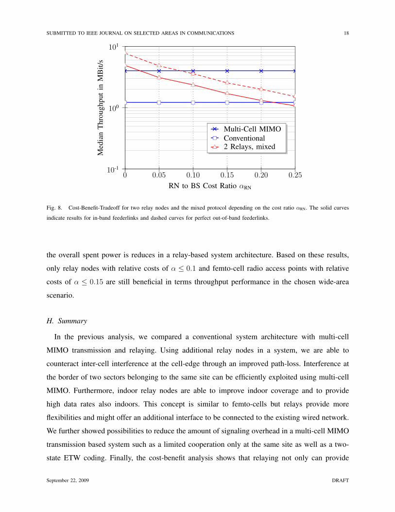
Based on this cost-normalization, Fig. 8 shows the cost-benefit tradeoff for the median through-
put. We can see that the mixed protocol only performs as well as multi-cell MIMO transmission
for #RN < 0.02 (if we consider in-band feederlinks) and has a higher median throughput than
a conventional system for #RN < 0.22. For our example of #RN = 0.1 the median throughput
drops by about 0.17 MBit/s compared to multi-cell MIMO transmission. In the case of using
an out-of-band feederlink the mixed protocol provides almost the same performance as multi-
cell MIMO transmission. Furthermore, due to the lower transmission power of relay node also
September 22, 2009 DRAFT
SUBMITTED TO IEEE JOURNAL ON SELECTED AREAS IN COMMUNICATIONS 18
10-1
100
101
0 0.05 0.10 0.15 0.20 0.25
RN to BS Cost Ratio #RN
Med
ian
Thro
ughput
inM
Bit
/s
+ + + + + +
Multi-Cell MIMO+Conventional2 Relays, mixed
Fig. 8. Cost-Benefit-Tradeoff for two relay nodes and the mixed protocol depending on the cost ratio #RN. The solid curves
indicate results for in-band feederlinks and dashed curves for perfect out-of-band feederlinks.
the overall spent power is reduces in a relay-based system architecture. Based on these results,
only relay nodes with relative costs of # $ 0.1 and femto-cell radio access points with relative
costs of # $ 0.15 are still beneficial in terms throughput performance in the chosen wide-area
scenario.
H. Summary
In the previous analysis, we compared a conventional system architecture with multi-cell
MIMO transmission and relaying. Using additional relay nodes in a system, we are able to
counteract inter-cell interference at the cell-edge through an improved path-loss. Interference at
the border of two sectors belonging to the same site can be efficiently exploited using multi-cell
MIMO. Furthermore, indoor relay nodes are able to improve indoor coverage and to provide
high data rates also indoors. This concept is similar to femto-cells but relays provide more
flexibilities and might offer an additional interface to be connected to the existing wired network.
We further showed possibilities to reduce the amount of signaling overhead in a multi-cell MIMO
transmission based system such as a limited cooperation only at the same site as well as a two-
state ETW coding. Finally, the cost-benefit analysis shows that relaying not only can provide
September 22, 2009 DRAFT
SUBMITTED TO IEEE JOURNAL ON SELECTED AREAS IN COMMUNICATIONS 19
better performance but also can be more cost-efficient. However, the cost-benefit analysis is not
able to account for those cases in which relays provide high-quality service for those areas where
neither conventional systems nor multi-cell MIMO transmission is able to provide the required
data rates.
V. CONCLUSIONS
In this paper, we compared different aspects of multi-cell MIMO transmission and relaying and
proposed a system architecture that integrates both techniques. Relaying provides a higher spatial
reuse of resources and is able to serve users at high data rates in otherwise shadowed areas.
Assuming relays are much cheaper in terms of their initial and operational expenditures, they
are a cost-efficient supplement for next-generation mobile communication systems. Furthermore,
the reduced requirements on the backhaul as well as the fact that existing sites in 2G and 3G
networks can be reused make a relay deployment attractive. Relays require less space than base-
stations and can therefore be deployed more flexibly. Using the integrated approach with relaying
and multi-cell MIMO transmission, we are able to support the most important scenarios in a
mobile communication system such as macro-cells for high-velocity users, micro-cells in densely
populated areas, high data rates indoors, and short-term deployments for special events using
relocatable relay nodes. The most challenging problem for relaying is the half-duplex constraint,
which requires that relay nodes can either transmit or listen on the same time-frequency resource.
Using multi-cell MIMO transmission on the feederlink, we can alleviate this constraint and
improve data rates on the link between base stations and relay nodes.
REFERENCES
[1] S. Vishwanath, N. Jindal, and A. Goldsmith, “Duality, achievable rates, and sum-rate capacity of Gaussian MIMO broadcast
channels,” IEEE Transactions on Information Theory, vol. 49, no. 10, pp. 2658–2668, October 2003.
[2] H. Weingarten, Y. Steinberg, and S. Shamai, “The capacity region of the Gaussian MIMO broadcast channel,” in IEEE
International Symposium on Information Theory, Chicago (IL), USA, June 2004, p. 174.
[3] R. Pabst, B. Walke, D. Schultz, P. Herhold, H. Yanikomeroglu, S. Mukherjee, H. Viswanath, M. Lott, W. Zirwas, M. Dohler,
H. Aghvami, D. Falconer, and G. Fettweis, “Relay-based deployment concepts for wireless and mobile broadband radio,”
IEEE Communications Magazine, vol. 42, no. 9, pp. 80–89, September 2004.
[4] P. Rost, G. Fettweis, and J. Laneman, “Opportunities, constraints, and benefits of relaying in the presence of interference,”
in IEEE International Conference on Communications, Dresden, Germany, June 2009.
[5] ETSI recommendation TR 30.03, “Selection procedure for the choice of radio transmission technologies of the UMTS,”
November 1997.
September 22, 2009 DRAFT
SUBMITTED TO IEEE JOURNAL ON SELECTED AREAS IN COMMUNICATIONS 20
[6] WINNER, “IST-Winner,” http://www.ist-winner.org, January 2009.
[7] IST-4-027756 WINNER II, “D6.13.7 Test scenarios and calibration issue 2,” December 2006.
[8] IST-4–027756 WINNER II, “D6.11.2 key scenarios and implications for WINNER II,” September 2006.
[9] IST-4-027756 WINNER II, “D1.1.2 WINNER II channel models,” September 2007.
[10] ——, “D1.1.1 WINNER II Interim channel models,” November 2006.
[11] S. Weinstein and P. Ebert, “Data transmission by frequency-division multiplexing using the discrete fourier transform,”
IEEE Transactions on Communications, vol. 19, no. 5, pp. 628–634, October 1971.
[12] L. Cimini, “Analysis and simulation of a digital mobile channel using orthogonal frequency division multiplexing,” IEEE
Transactions on Information Theory, vol. 33, no. 7, pp. 665–675, July 1985.
[13] J. Laneman, D. Tse, and G. Wornell, “Cooperative diversity in wireless networks: Efficient protocols and outage behavior,”
IEEE Transactions on Information Theory, vol. 50, no. 12, pp. 3062–3080, December 2004.
[14] T. Nielsen, J. Wigard, and P. Mogensen, “On the capacity of a GSM frequency hopping network with intelligent underlay-
overlay,” in IEEE Vehicular Technology Conference (VTC), vol. 3, Phoenix (AZ), USA, May 1997, pp. 1867–1871.
[15] F. Boye, “Analyse und bewertung der implikationen von relaying auf die systemeigenschaften eines zellularen 4g-
mobilfunknetzes mit mehrantennenubertragung,” Master’s thesis, Technische Universitat Dresden, Dresden, Germany, 2007.
[16] S. Shamai and B. Zaidel, “Enhancing the cellular downlink capacity via co-processing at the transmitting end,” in IEEE
Vehicular Technology Conference (VTC), vol. 3, Rhodes, Greece, May 2001, pp. 1745–1749.
[17] S. Shamai, O. Somekh, O. Simeone, A. Sanderovich, B. Zaidel, and H. Poor, “Cooperative multi-cell networks: Impact of
limited-capacity backhaul and inter-users links,” in Joint Workshop on Coding and Communications, Durnstein, Austria,
October 2007.
[18] P. Marsch and G. Fettweis, “On base station cooperation schemes for downlink network MIMO under a constrained
backhaul,” in IEEE Global Communications Conference, New Orleans (LA), USA, November 2008.
[19] M. Costa, “Writing on dirty paper,” IEEE Transactions on Information Theory, vol. IT-29, no. 3, pp. 439–441, May 1983.
[20] A. Lapidoth, S. Shamai, and M. Wigger, “On the capacity of fading mimo broadcast channels with imperfect transmitter
side information,” in Allerton Conference on Communications, St. Louis (MO), USA, November 2005.
[21] T. Han and K. Kobayashi, “A new achievable rate region for the interference channel,” IEEE Transactions on Information
Theory, vol. IT-27, no. 1, pp. 49–60, January 1981.
[22] G. Caire and S. S. (Shitz), “On the achievable throughput of a multiantenna Gaussian broadcast channel,” IEEE Transactions
on Information Theory, vol. 49, no. 7, pp. 1691–1706, July 2003.
[23] R. Etkin, D. Tse, and H. Wang, “Gaussian interference channel capacity to within one bit,” IEEE Transactions on
Information Theory, vol. 54, no. 12, pp. 5534–5562, December 2008.
[24] V. Chandrasekhar, J. Andrews, and A. Gatherer, “Femtocell networks: A survey,” IEEE Communications Magazine, vol. 46,
no. 9, pp. 59–67, September 2008.
September 22, 2009 DRAFT

SUBMITTED TO IEEE JOURNAL ON SELECTED AREAS IN COMMUNICATIONS 1
Integration of Multi-Cell MIMO Transmission andRelaying in Mobile Communication Systems
Peter Rost, Student Member, IEEE, Gerhard Fettweis, IEEE
Fellow, and J. Nicholas Laneman, Senior Member, IEEE
Abstract— In this paper, relaying and multi-cell MIMO trans-mission are investigated as possibilities to improve the resourcereuse and to more flexibly organize cellular networks. Ouranalysis focuses on approaches for future cellular systems, whichjointly exploit relaying and multi-cell MIMO transmission. Weevaluate these approaches using the system level model of theEuropean research project WINNER and analyze the achievablethroughput under practical constraints. Finally, we provide ananalysis of the cost-benefit tradeoff in relay-assisted systems.It turns out to be a reasonable choice for the downlink ifmultiple base stations cooperatively serve relays and relays coor-dinate their resources to serve users. The backhaul requirementsbetween multiple sites can be reduced by only considering acooperation of base-stations co-located at the same site, which stillprovides almost the same gains as multi-cell MIMO transmissionfrom different sites.
Index Terms— Relaying, multiple antenna systems, cellularnetworks, half-duplex constraint, cost-benefit tradeoff, wide-areacoverage scenario, Manhattan-area high-throughput scenario
I. INTRODUCTION
A. Motivation of our work
In current and future mobile communication systems boththe required data rates and the number of mobile subscribersincrease exponentially. Since the capacity per cell is limited,the spatial reuse of available resources must increase. Hence,cells become smaller, which is coupled with higher carrierfrequencies offering higher path-loss and therefore better sep-aration of cells. Since each cell is served by its own (logical)radio access point (RAP), 4G systems demand a large numberof RAPs, which can be economically satisfied by additional,cheaply deployed relay nodes.
Among the most serious challenges in current and futuremobile communication systems is the mitigation or avoidanceof inter-cell interference. Future mobile communication sys-tems are likely to use multi-cell MIMO approaches in whichmultiple base stations cooperatively serve user terminals usingtechniques introduced in the context of the MIMO broadcastchannel [1], [2]. Furthermore, additional relay nodes will helpto provide high data rates in otherwise shadowed areas as wellas to further improve the channel conditions at cell borders [3].
Consider a mobile communication system in which multiplebase station antenna arrays at the same cell site (typicallythree) serve adjacent sectors within the cell site. These base
Manuscript submitted September 22, 2009. G. Fettweis and P. Rost are withthe Vodafone Chair for Mobile Communications Systems, Technische Univer-sitat Dresden (TUD), Dresden, Germany (Email: {fettweis, rost}@ifn.et.tu-dresden.de). J. N. Laneman is with the University of Notre Dame (IN), USA(Email: [email protected])
station antenna arrays are often mounted on a single tower andcan share the same radio and processing hardware. Thereforemulti-cell MIMO transmission can be easily implemented. Bycontrast, multi-cell MIMO transmission from base stationsat different sites requires a substantial backhaul in order toexchange channel state information (CSI) and data. In eitherscenario, these regions could be better served by additional re-lay nodes, which implement interference mitigation techniquesand improve the spatial reuse. These observations motivatethe study of multi-cell MIMO and relaying integrated in onesystem architecture, which is the focus of this paper.
B. Outline and Contribution
We explore system architectures based upon the trans-mission schemes introduced in [4], where we employed alink-level analysis of the relay-assisted interference channel.These schemes are able to combine the benefits of multi-cell MIMO transmission and relaying in one integrated systemarchitecture. We apply them to the system model of a next-generation mobile communication network and compare theperformance of a conventional system, a system using multi-cell MIMO only, a system using relaying only, and a systemin which both multi-cell MIMO and relaying are integrated.This comparison is done for two different propagation sce-narios, which demonstrate the ability of the integrated systemapproach to counteract inter-cell interference and to improveindoor coverage. Our analysis pays special attention to possi-bilities for reducing complexity and signaling overhead in 4Gnetworks in order to improve the cost-benefit tradeoff.
The remainder of the paper is organized as follows. SectionII introduces the system model and reviews a proposed archi-tecture for a next generation mobile communication system.Section III discusses the system and protocol design, andsummarizes the approaches for the mobile communicationsystem. Section IV then analyzes these approaches usingvarious constraints and figures of merit. Finally, Section Vconcludes the paper with further comments on implicationsfor future mobile communication systems.
II. SYSTEM MODEL
A. Propagation scenarios
This paper considers the proposed system architecture of theEuropean research project WINNER [6] for a next-generationmobile communication system. WINNER considers threepropagation scenarios: indoor, wide-area (macro-cellular), and

SUBMITTED TO IEEE JOURNAL ON SELECTED AREAS IN COMMUNICATIONS 2
BS
BS
BS
BS
BS
BS
BS
(a) Wide-area scenario with one tier of interferingsites. Triangles indicate relay nodes and arrows themain lobe direction in each cell.
200
m30
m
BS
BS
BS
BS
BS
BS
BS
BSBS
BS
BS
BS
BS
BS
BS
(b) Manhattan-area scenario as defined in [5].Blue triangles indicate outdoor relays and redsquares indoor relays.
Fig. 1. Two reference scenarios considered in this paper.
Manhattan street-grid (micro-cellular) [7]1. In this paper, wefocus on the two scenarios wide-area and Manhattan street-grid because both scenarios allow for an analysis of thetwo most challenging problems in 4G networks: inter-cellinterference and indoor coverage. Wide-area corresponds to ahexagonal cell-structure, which is illustrated in Fig. 1(a). Eachsite (indicated with ”BS”) is equipped with three base stationantenna arrays serving three adjacent sectors (with main lobedirections indicated by arrows) and two stationary relays persector (indicated by triangles). Sites are uniformly placed, suchthat the distance between two adjacent sites is always given bydis = 1000m. Our numerical analysis in Section IV considersone central site, which is surrounded by two tiers of a totalof 18 interfering sites. Furthermore, the number of users percell may vary as we keep the number of overall users constantand ensure that on average 90 Users per km2 are uniformlydistributed within the system [8]. Users are assigned to RAPsbased on their path-loss to the respective base station or relay
1All referred WINNER documents are publicly available on http://www.ist-winner.org
Manhattan-area Wide-area
BS to RN B5c B5aBS to indoor UT B4BS to outdoor UT B1 C2RN to indoor UT B4RN to outdoor UT B1 C2indoor RN to indoor UT A1
TABLE I
USED CHANNEL MODELS, WHICH ARE DEFINED IN [9].
node. Hence, the actual cell coverage might vary significantlyfrom the regular layout in Fig. 1.
The Manhattan-area scenario models a regular street-grid asproposed by the UMTS 30.03 recommendation [5] (see Fig.1(b)). Each base station is now equipped with omni-directionalantennas and is supported by four stationary relay nodes: tworelay nodes outdoors (indicated by a triangle) and two relaynodes indoors (indicated by a square). If we place relays withomni-directional antennas on street crossings, we significantlyincrease the probability that an outdoor user terminal has line-of-sight (LOS) with a RAP. Indoor relays improve the indoorcoverage due to a more uniform power distribution and thepossibility to place relay nodes with a sufficiently strong linktowards the base station. In our simulation-based analysis inSection IV, we use overall 44 cells but only consider the resultsfor the three inner cells. Compared to the wide-area scenario,we assume a higher user density with 250 Users per km2
placed both on streets and within buildings [8].The WINNER system offers a variety of channel models
suitable for each scenario. Each consists of a model for theprobability that a strong LOS link exists, the path-loss model,and the power delay profile, which models the small scalefading assuming each tap is Gaussian distributed. We furtherassume block fading in which each channel realization isindependently generated. Table I lists all channel models,which are used in our paper’s numerical analysis. Each channelmodel is described in detail in [9].
B. Air interface
In our model, we apply Orthogonal Frequency DivisionMultiplexing (OFDM) [11], [12] at a carrier frequency fc =3.95GHz with bandwidth Bw = 100MHz and Nc = 2048subcarriers. Since signal delays are not considered, we choosetime division duplexing (TDD) for both the wide-area and theManhattan-area scenario. All further air interface parametersare listed in Table II and described in further detail in [7].
We further assume Gaussian alphabets, perfect rate adap-tation, and infinite blocklengths in order to use the relevantcapacity expressions [4] and to have an upper bound onthe achievable rates. Throughout the following discussion weassume perfect channel estimation and that the system isperfectly synchronized. Of course, especially in systems sup-porting relay nodes, synchronization and channel estimationare significant challenges but these issues are outside the scopeof this work. This paper considers neither automatic repeat-request (ARQ), which is not necessary due to the perfectlink adaptation, nor quality-of-service (QoS), since all users
SUBMITTED TO IEEE JOURNAL ON SELECTED AREAS IN COMMUNICATIONS 3
User density90 per km2 in Wide-area,250 per km2 in Manhattan-area
Average no. users/cell 26 in Wide/Manhattan-areaChannel models as defined in [10]Number of antennas BS/ RN / UT
4 / 1 / 1
BS transmit power 46 dBmRN transmit power 37 dBmUT noise figure 7 dBNoise power spectraldensity
!174 dBm/Hz
FFT-Size 2048Carrier frequency 3.95 GHzFFT bandwidth 100 MHzOFDM-Symbol duration 20.48 µsSuperframe duration 5.89 msGuard interval 2.00 µsUsed subcarriers [!920; 920] \ {0}
Channel state informa-tion
assumed perfect at transmitter and receiver
TABLE II
PARAMETERS OF THE WINNER SYSTEM
1
X1
3
X3 : Y3
5
Y5
2
X2
4
X4 : Y4
6
Y6
C1,2/C2,1
Fig. 2. Relay-assisted interference channel with two sources S = {1, 2}, tworelays R = {3, 4}, and two destinations D = {5, 6}. Both source nodes areconnected by conference links with capacities C1,2 and C2,1, respectively.Channel inputs are denoted by Xt and channel outputs are denoted by Yt.
are assumed to have equal priority. The considered schedulerassumes full queues for each user, which implies that allavailable resources are fully exploited even though in a realsystem this depends on the type of transmitted data. Weaddress the problem of an in-band feederlink between basestation and relay node, which implies that relay-buffers mightbe empty due to an unexpected high throughput on the linksbetween a relay and its assigned users.
III. SYSTEM AND PROTOCOL DESIGN
In [4] we introduced the relay-assisted interference channel,which is illustrated in Fig. 2. This channel models the casein which two communication pairs are supported by relaynodes. Due to conference links between the source nodes, itoffers the possibility of multi-cell MIMO transmission fromboth source nodes, i. e., inter-path cooperation. Additionally,destination nodes within one path can combine the source andrelay transmission, i. e., inter-subsystem cooperation, which isalso referred to as cooperative relaying [13]. In the following,we introduce different system architectures, which implementinter-path and inter-subsystem cooperation and were analyzedat the link-level in [4].
A. Non-Relaying Protocols
Conventional system architectures without relay nodes(X3 = X4 = 0) do not implement any kind of inter-pathcooperation but coordinate their resources using TDD andfrequency division duplexing (FDD). In order to improve theresource reuse factor, current systems divide the availablebandwidth into an edge band and center band [14]. Edge bandresources are used to serve users at the cell edge with highinter-cell interference. Furthermore, this protocol reserves acenter band, which is used by all cells to serve users withhigh signal-to-interference-and-noise ratio (SINR). The actualassignment of users to edge and center band uses the expectedlong-term SINR, which is assumed to be perfectly known. Inour analysis, a user is served using edge band resources if theexpected SINR drops below 10 dB, based upon the empiricalstudies in [15].
In Section I, we already introduced multi-cell MIMO as astrategy to implement inter-path cooperation in systems, whichdo not employ relay nodes. The idea of multi-cell MIMOgoes back to an early work of Shamai and Zaidel [16], whointroduced the concept in order to improve data rates andfairness. Shamai et al. [17] analyze user cooperation in thedownlink of a multicell scenario. Among other scenarios, theyconsider the case of unlimited backhaul and user cooperationover a limited-capacity, orthogonal inter-user link. Similarly,Marsch and Fettweis derive in [18] achievable rate regions iftransmitter cooperation is possible.
Multi-cell MIMO offers an opportunity to exploit inter-ference instead of avoiding it. If we consider multiple basestations as one virtual antenna array with full channel anddata knowledge and perfect synchronization, we can employthe same strategies as for the MIMO broadcast channel, e. g.dirty paper coding (DPC) [19]. If the channel between basestations and user terminals is changing quickly, it might be notpossible to implement multi-cell MIMO without significantperformance loss [20]. In this paper, we consider multi-cellMIMO transmission from three base stations. In order to co-ordinate their transmissions, all base stations are connected byan unlimited backhaul, which provides the means to perfectlyexchange CSI and data.
B. Relay-Only Protocol
The relay-only protocol has all users served using relaynodes. In order to mitigate the interference introduced bythe additional relay nodes, we consider Han-Kobayashi (HK)coding [21] on the relay-to-destination links (R!D).
The expected bottleneck in such a system is the in-band
feederlink2 between source and relay, which must share re-sources used for the communication on the source-to-relaylinks (S!R). In order to improve the data rates on the source-to-relay links, we consider multi-cell MIMO transmissionbetween base stations and relay nodes. Compared to multi-cell MIMO transmission from base stations to user terminals,the signaling overhead is reduced, because relay nodes donot move and experience LOS towards the base station.
2Note that we differentiate the backhaul connecting multiple sites and in-band feederlinks, which connect base stations and relay nodes.
SUBMITTED TO IEEE JOURNAL ON SELECTED AREAS IN COMMUNICATIONS 4
Inter-PathCoordination Cooperation
Inte
r-S
ub
syst
em
Co
ord
inat
ion
• TDD or HK onboth hops
• Direct transmis-sion
• DPC on S ! Ror S ! D
• HK or TDD onR ! D
Co
op
erat
ion • Cooperative re-
laying• Source and re-
lay jointly em-ploy DPC
• All nodes formone virtual an-tenna array
TABLE III
THE INDIVIDUAL PROTOCOLS CLASSIFIED BY THEIR ABILITY TO
COOPERATE.
Furthermore, the user grouping is simplified as only a smallnumber of fixed relay nodes is considered.
C. An integrated approach
Link-level results in [4] suggest that the previous protocolmight not be able to provide the required performance figuresfor users close to the base station. Hence, we consider amixed protocol in which users are either served using multi-cell MIMO transmission or relaying. Based on the path-loss tothe individual nodes, with a penalty for the lower transmissionpower of relay nodes, each user is assigned either to a basestation or to a relay node. Furthermore, either base stations orrelay nodes transmit within a certain part of the spectrum, butnot both. The partitioning of the available bandwidth amongboth protocols is done adaptively in order to maintain fairness.
Using HK coding the interference mitigation can be doneautonomously without extensive network planning beforehand.This simplifies the system design while reducing protocolcomplexity. If relay nodes act as base stations towards userterminals and as user terminals towards base stations, we donot need additional wireless interfaces. Furthermore, the mixedprotocol reduces the necessary complexity by using algorithmsthat are supposed to be implemented in 4G systems anyway.Almost all of the additional complexity has to be spent in thescheduler, which must not be designed independently of thephysical layer. All possible protocols are summarized in TableIII and grouped based on their ability to cooperate betweenmultiple paths or subsystems.
D. Simplifications
In [4] DPC and HK coding have been used. Both techniquesrequire an extensive optimization in order to determine the cor-rect precoding matrices (DPC) or power levels (HK coding). Ifwe apply both techniques to a mobile communication system,we would have to cope with a significant computationaloverhead. Instead, we employ in our analysis Zero-ForcingDPC (ZF-DPC) [22], instead of DPC with optimal precoding
matrices, and Etkin-Tse-Wang (ETW) coding [23], instead ofHK coding over all possible power levels.
ZF-DPC uses the LQ-decomposition of the compound chan-nel matrix and by precoding with the unitary matrix Q, theeffective channel becomes a triangular matrix. Then, DPC isapplied such that each user sees an interference-free link. Dueto the large number of user terminals and base stations, theuser grouping is a computationally expensive problem. Hence,we apply a simplified form of user grouping in which theassignment of user terminals to the individual base stationsis done based on the path-loss between base station and userterminal, i. e., each user is assigned to the three base stationswith the smallest path-loss towards this user. Furthermore, theuser grouping algorithm ensures that cooperating base stationsserve those users with similar preferences.
ETW coding is a particular form of HK coding in which thepower levels can be determined directly and which achievesrates within 1 bpcu of capacity. The optimal form of ETWcoding must determine the power levels for each subcarrier (orframe) individually. In order to reduce the signaling overhead,we use the long-term SINR statistics (constant over both super-frames) instead of the fast-fading coefficients to determine thepower levels. We further consider a two-state ETW coding inwhich only the power levels 0 and 1 are allowed, i. e., a relaysends either only a private message or a common message.
As with base stations, we use a simple form of user groupingfor the assignment of users to relay nodes. In order to ensureefficient interference mitigation each user is assigned to therelay node with the smallest path-loss towards this user. Therelay node with the second-smallest path-loss towards this useris chosen and selected for the ETW coding. Based on thisselection another user with the same preferences is chosenand as many resources as possible are assigned to this relay-user-pair.
IV. NUMERICAL ANALYSIS
In order to evaluate the individual protocols and to under-stand their effects on the user performance, we discuss in detailthe following aspects of multi-cell MIMO transmission andrelaying:
• Ability of multi-cell MIMO transmission and relaying tocounteract inter-cell interference
• Service improvements for indoor users• Comparison of relaying and femto-cells• Reduction of the required backhaul and signaling over-
head• Cost-benefit tradeoff of relay-based networks.
A. Simulation methodology
In order to evaluate the different protocols, we use a snap-shot based, system-level simulation, which does not explicitlymodel any user mobility. It rather models the effects of mobi-lity on the user’s channel instead of moving a particular userand tracking its performance. The latter requires significantlymore frames in order to reflect the low velocity of users.Therefore users are randomly placed, and for each snapshottwo superframes are simulated before the next snapshot is
SUBMITTED TO IEEE JOURNAL ON SELECTED AREAS IN COMMUNICATIONS 5
10-2
10-1
100
10-2 10-1 100 101 102
Throughput ! in MBit/s
Pr{!
(·,·
)!
!}
+
+
+
++ +
ConventionalMulti-Cell MIMO+2 Relays, relay-only2 Relays, mixed8 Relays, relay-only
Fig. 3. Throughput results for the wide-area scenario using an in-bandfeederlink.
drawn. For each frame within a superframe an independentinstance of the small scale fading process is drawn and theuser scheduling is performed.
The overall area is partitioned into rectangles of equal size.In case of the wide-area scenario they are of size 30m"30m,and in case of the Manhattan-area scenario they are of size10m " 10m. For each user the corresponding spatial block(x, y) is determined and the average throughput !(x, y) =Et {!(x, y, t)} over all users, which have been placed in thisblock, is used to determine the number of resources. Using afair scheduler the number of resources assigned to a user isproportional to !!1(x, y). The fact that we use the averagethroughput reflects that we try to achieve a good tradeoffof high system throughput and fairness. In order to achievean improved fairness within the system, it would be moresuitable to use the 5% quantile of throughput !5%, withPr {!(x, y, t) ! !5%} ! 5%. In this way, a user with a highthroughput variance gets even more resources in order toimprove the 5% quantile of throughput at the expense of otherusers’ performance.
B. Throughput Performance in Wide-Area
At first we want to explore how relaying and multi-cellMIMO cope with inter-cell interference. Fig. 3 shows thecumulative distribution function (CDF) of the user throughput!(x, y, t) in the wide-area scenario. We further list in TableIV the median throughput !, the 5% quantile throughput !5%,and the standard deviation throughput " =
!
Var{!(x, y, t)}for the wide-area and Manhattan-area scenario. In a con-ventional system, we only achieve a 5% quantile throughputof about !5% = 0.13MBit/s and a median throughput ofabout ! = 1.2MBit/s. By contrast, if we use multi-cellMIMO transmission to exploit the inter-cell interference, wehave !5% = 0.6MBit/s and ! = 3.5MBit/s. Hence, not
Scenario / Protocol ! [MBit/s] " [MBit/s] !5% [MBit/s]
Wid
e-ar
ea
Conventional 1.2 3.3 0.13Multi-Cell MIMO 4.3 4.9 0.6
2 Relays, relay-only 2.9 3.5 0.052 Relays, mixed 4.9 5.2 0.7
8 Relays, relay-only 8.6 8.4 1.4
Man
hat
tan
-are
a Conventional 0.11 5.1 0.3 · 10!3
Multi-Cell MIMO 0.16 1.2 0.5 · 10!3
2 Relays, relay-only 0.15 1.2 0.4 · 10!3
2 Relays, mixed 0.6 3.3 3 · 10!3
4 Relays, relay-only 1.9 16.6 0.34 Relays, mixed 1.7 18.4 0.3
TABLE IV
NUMERICAL THROUGHPUT RESULTS FOR THE WIDE-AREA AND THE
MANHATTAN-AREA SCENARIO USING AN IN-BAND FEEDERLINK.
only is the cell throughput increased but also the worst-userperformance is significantly improved. If relays are deployedand all users are served using them, the median throughputimproves, but the worst-user performance severely drops.Since relays only improve the channel conditions for thoseusers at the cell edge and users close to the relay node, theworst users are now located close to the base station. Contraryto the relaying-only protocol, the mixed protocol is able toimprove both median throughput and worst-user performanceand outperforms all other protocols. In this case, users closeto a base station are served directly by the base stations usingmulti-cell MIMO and users at the cell edge are assigned torelays. This shows that the improved channel conditions dueto the deployment of relay nodes outweighs the loss due tothe half-duplex constraint, and interference between multiplesites is counteracted through interference mitigation schemesused by relay nodes. On the other hand, interference betweensectors at the same site is exploited using multi-cell MIMOtransmission. Due to the limited resources for the source-to-relay links, a higher relay node density does not necessarilyincreases the performance. In Fig. 3, we see the throughput foreight relays per sector, which are uniformly distributed. Dueto the half-duplex limitation, the performance only slightlyimproves compared to the results for two relays per sector.
C. Throughput Performance in Manhattan-Area
In addition to the ability to improve the cell-edge per-formance, relaying has the potential to improve the indoorcoverage in a micro-cellular scenario. Fig. 4 shows the resultsfor the Manhattan-area scenario. We can again see that multi-cell MIMO transmission improves the performance comparedto a conventional system. However, the difference betweenworst and median throughput performance is very high, whichresults primarily from indoor users suffering from very badchannel conditions. The same effect can be seen if only twooutdoor relay nodes are deployed. Only four relay nodes (twooutdoor and two indoor relays) are able to provide reasonableperformance figures for both worst user and median userperformance (!5% = 0.3MBit/s and ! = 1.8MBit/s). Wecan further see that the relay-only protocol provides the sameperformance figures as the mixed protocol, which implies thatonly relay nodes but no users benefit from multi-cell MIMO

SUBMITTED TO IEEE JOURNAL ON SELECTED AREAS IN COMMUNICATIONS 6
10-2
10-1
100
10-4 10-3 10-2 10-1 100 101
Throughput ! in MBit/s
Pr{!
(·,·
)!
!}
+
+
+
+
+
++
++ +
ConventionalMulti-Cell MIMO+2 Relays, relay-only2 Relays, mixed4 Relays, relay-only4 Relays, mixed
Fig. 4. CDF of the expected throughput in the Manhattan-area scenario. Inthe case only two relay nodes per sector are used, both are deployed outdoors.
10-2
10-1
100
10-4 10-3 10-2 10-1 100 101
Throughput ! in MBit/s
Pr{!
(·,·
)!
!}
+
+
+
+
+
++
++ +
ConventionalMulti-Cell MIMO+2 Relays, relay-only2 Relays, mixed4 Relays, relay-only4 Relays, mixed
Fig. 5. Results for out-of-band feeder deployed in Manhattan-area
transmission in this micro-cellular scenario.
D. Femto-Cells vs. Relaying
Currently, an alternative way of improving indoor coverageand data rate is to use femto-cells [24], where small RAPs arehome-deployed and connected to the available wired network,e. g. DSL. This is similar to relaying even though relaying usesthe same PHY interface for the source-to-relay link instead ofa wired network. Fig. 5 shows the results for the Manhattan-area scenario and using femto-cells instead of relay nodes.In these results, we assume that femto-cells do not requirein-band feederlink resources and have access to a backhaul
10-2
10-1
100
10-1 100 101 102
Throughput ! in MBit/s
Pr{!
(·,·
)!
!}
Fast-fading based
Two-State ETWTDD
Fig. 6. Throughput-CDF and comparison of correct (fast-fading based) ETWcoding (dashed lines) and path-loss-based ETW coding (solid lines).
network, which always provides the required data rates anddoes not limit the achievable rates on the relay-to-terminallinks. Only the performance of four relay nodes improvesusing femto-cells due to the fact that femto-cell relay nodescan now additionally use those resources that would otherwisebe used to serve relays.
The necessity to connect the indoor RAP to the data networkmakes the deployment less flexible and more expensive com-pared to relay nodes that use in-band feederlinks. Furthermore,it requires the availability of a high-speed network and it onlyworks indoors where such a network is available. However, italso shows the flexibility of the relay concept because indoorrelay nodes could be equipped with an additional interfaceto the local wired network in order to further improve theperformance.
E. Reduced Signaling Overhead
Since relay nodes are not directly connected with each other,the exchanged signaling overhead between them must be keptat a minimum. In Fig. 6, we compare the performance ofoptimal ETW coding using fast-fading information, a two-state ETW coding with two possible power assignments (eitheronly private or common messages) and using the long-termSINR, and TDD between relay nodes and user terminals.These results show that there are only minor performanceimprovements if fast-fading CSI is used. The usage of path-loss information significantly reduces the necessary signalingoverhead and makes ETW coding feasible. The results alsoreveal that a two-state ETW coding is able to achieve almostthe same performance. This suggests that it is sufficientto quantize the power level with 1 bit. Compared to TDD,ETW coding needs no central scheduler that coordinates theassignment of resources to each relay node based on the globalpath-loss information. The power assignment for ETW codingcan be done at each relay node based on the path-loss betweenthe relay and the assigned user terminals.

SUBMITTED TO IEEE JOURNAL ON SELECTED AREAS IN COMMUNICATIONS 7
10-2
10-1
100
10-1 100 101 102
Throughput ! in MBit/s
Pr{!
(·,·
)!
!}
+
+
+
++ +
+
+
+
++ + +
ConventionalMulti-Cell MIMO+2 Relays, mixed
Fig. 7. Throughput CDF for a system with no inter-site cooperation. Relaynodes and users are cooperatively served by base stations at the same site(solid line). For comparison the dashed line shows the performance if usersare served cooperatively by multiple sites.
F. Reduced Backhaul Requirements
Previous results in this paper have shown that users aremore likely to be served by relay nodes instead of theassigned base station. Therefore, only a small area is servedusing multi-cell MIMO transmission. In these areas, it isan alternative to serve those areas either without multi-cellMIMO transmission (main lobe direction) or using a multi-cell MIMO transmission of base stations at the same site(border of two sectors, which belong to the same site). Fig. 7shows the achievable throughput for a system in which relaysand users can be cooperatively served by base stations atdifferent sites (solid line) and for a system in which multi-cellMIMO transmission is limited to base stations at the same site(dashed lines). The former corresponds to a system requiringsubstantial backhaul, which must support the required datarates to exchange the additional CSI and message information.The latter corresponds to a conventional backhaul, which isalready used in current mobile communication systems. Wecan see that a system architecture that only uses multi-cellMIMO transmission, suffers from a significant performanceloss if multi-cell MIMO transmission is limited to one site.On the other hand, if we use the integrated approach withrelaying and multi-cell MIMO transmission, the performanceremains almost unaffected. A system with multi-cell MIMOtransmission only at one site requires less backhaul and ismore robust for scenarios with low coherence time/frequency.
G. Cost-benefit tradeoff
The previous discussion did not account for the additionaldeployment costs of relay nodes. In order to normalize theresults we have to keep constant either the costs for thesystem deployment or the system performance. This paper usesthe former way of normalizing the results. In the following,we use CSite to denote the costs of a site and CRelay todenote the costs of a relay node, which includes hardware
10-1
100
101
0 0.05 0.10 0.15 0.20 0.25RN to BS Cost Ratio "RN
Med
ian
Th
rou
gh
pu
tin
MB
it/s
+ + + + + +
Multi-Cell MIMO+Conventional2 Relays, mixed
Fig. 8. Cost-Benefit-Tradeoff for two relay nodes and the mixed protocoldepending on the cost ratio !RN. The solid curves indicate results for in-bandfeederlinks and dashed curves for perfect out-of-band feederlinks.
costs, rental costs, average costs for power supply as well asbackhaul costs (in case of a base station). Backhaul expensesdepend on the BS density and therefore affect the relativecosts, which is not considered in this work. Furthermore, weuse "RN = CRelay/CSite to denote the costs of a relay noderelative to a site. Table V gives an example of the costs for arelay node and a site. For this particular example the relativerelay costs are given by "RN = 0.1, which is used in theremainder.
Item of Expenditure Relay Node Site (with 3 BS)
Hardware 10 kEUR 80 kEURLoan 3 years at 8 % 8 years at 8 %Installation 5 kEUR 30 kEURRental costs 100 EUR per month 1000 EUR per monthEnergy costs(at 10 Cent per kWh)
438 EUR p.a. (500W) 4.4 kEUR p.a. (5kW)
Life-Span 10a 10a
Cost-Ratio !RN = CRelay/CSite = 0.1
TABLE V
EXAMPLE FOR INITIAL AND OPERATING COSTS FOR A RELAY NODE AND
SITE WITH THREE BASE STATIONS.
Under the assumption of a regular grid of sites and withNRelay relays deployed at each site, the inter-site distance ina relay-based deployment is given by
dis (") = dis
!
1 + "RNNRelay, (1)
in order to normalize the deployment costs (dis is the inter-sitedistance in a system without relays).
Based on this cost-normalization, Fig. 8 shows the cost-benefit tradeoff for the median throughput. We can see thatthe mixed protocol only performs as well as multi-cell MIMOtransmission for "RN < 0.02 (if we consider in-band feeder-links) and has a higher median throughput than a conventionalsystem for "RN < 0.22. For our example of "RN = 0.1 themedian throughput drops by about 0.17MBit/s compared to
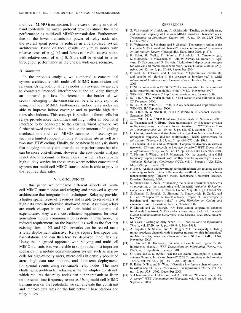
SUBMITTED TO IEEE JOURNAL ON SELECTED AREAS IN COMMUNICATIONS 8
multi-cell MIMO transmission. In the case of using an out-of-band feederlink the mixed protocol provides almost the sameperformance as multi-cell MIMO transmission. Furthermore,due to the lower transmission power of relay node alsothe overall spent power is reduces in a relay-based systemarchitecture. Based on these results, only relay nodes withrelative costs of ! ! 0.1 and femto-cell radio access pointswith relative costs of ! ! 0.15 are still beneficial in termsthroughput performance in the chosen wide-area scenario.
H. Summary
In the previous analysis, we compared a conventionalsystem architecture with multi-cell MIMO transmission andrelaying. Using additional relay nodes in a system, we are ableto counteract inter-cell interference at the cell-edge throughan improved path-loss. Interference at the border of twosectors belonging to the same site can be efficiently exploitedusing multi-cell MIMO. Furthermore, indoor relay nodes areable to improve indoor coverage and to provide high datarates also indoors. This concept is similar to femto-cells butrelays provide more flexibilities and might offer an additionalinterface to be connected to the existing wired network. Wefurther showed possibilities to reduce the amount of signalingoverhead in a multi-cell MIMO transmission based systemsuch as a limited cooperation only at the same site as well as atwo-state ETW coding. Finally, the cost-benefit analysis showsthat relaying not only can provide better performance but alsocan be more cost-efficient. However, the cost-benefit analysisis not able to account for those cases in which relays providehigh-quality service for those areas where neither conventionalsystems nor multi-cell MIMO transmission is able to providethe required data rates.
V. CONCLUSIONS
In this paper, we compared different aspects of multi-cell MIMO transmission and relaying and proposed a systemarchitecture that integrates both techniques. Relaying providesa higher spatial reuse of resources and is able to serve users athigh data rates in otherwise shadowed areas. Assuming relaysare much cheaper in terms of their initial and operationalexpenditures, they are a cost-efficient supplement for next-generation mobile communication systems. Furthermore, thereduced requirements on the backhaul as well as the fact thatexisting sites in 2G and 3G networks can be reused makea relay deployment attractive. Relays require less space thanbase-stations and can therefore be deployed more flexibly.Using the integrated approach with relaying and multi-cellMIMO transmission, we are able to support the most importantscenarios in a mobile communication system such as macro-cells for high-velocity users, micro-cells in densely populatedareas, high data rates indoors, and short-term deploymentsfor special events using relocatable relay nodes. The mostchallenging problem for relaying is the half-duplex constraint,which requires that relay nodes can either transmit or listenon the same time-frequency resource. Using multi-cell MIMOtransmission on the feederlink, we can alleviate this constraintand improve data rates on the link between base stations andrelay nodes.
REFERENCES
[1] S. Vishwanath, N. Jindal, and A. Goldsmith, “Duality, achievable rates,and sum-rate capacity of Gaussian MIMO broadcast channels,” IEEETransactions on Information Theory, vol. 49, no. 10, pp. 2658–2668,October 2003.
[2] H. Weingarten, Y. Steinberg, and S. Shamai, “The capacity region of theGaussian MIMO broadcast channel,” in IEEE International Symposiumon Information Theory, Chicago (IL), USA, June 2004, p. 174.
[3] R. Pabst, B. Walke, D. Schultz, P. Herhold, H. Yanikomeroglu,S. Mukherjee, H. Viswanath, M. Lott, W. Zirwas, M. Dohler, H. Agh-vami, D. Falconer, and G. Fettweis, “Relay-based deployment conceptsfor wireless and mobile broadband radio,” IEEE Communications Mag-azine, vol. 42, no. 9, pp. 80–89, September 2004.
[4] P. Rost, G. Fettweis, and J. Laneman, “Opportunities, constraints,and benefits of relaying in the presence of interference,” in IEEEInternational Conference on Communications, Dresden, Germany, June2009.
[5] ETSI recommendation TR 30.03, “Selection procedure for the choice ofradio transmission technologies of the UMTS,” November 1997.
[6] WINNER, “IST-Winner,” http://www.ist-winner.org, January 2009.[7] IST-4-027756 WINNER II, “D6.13.7 Test scenarios and calibration issue
2,” December 2006.[8] IST-4–027756 WINNER II, “D6.11.2 key scenarios and implications for
WINNER II,” September 2006.[9] IST-4-027756 WINNER II, “D1.1.2 WINNER II channel models,”
September 2007.[10] ——, “D1.1.1 WINNER II Interim channel models,” November 2006.[11] S. Weinstein and P. Ebert, “Data transmission by frequency-division
multiplexing using the discrete fourier transform,” IEEE Transactionson Communications, vol. 19, no. 5, pp. 628–634, October 1971.
[12] L. Cimini, “Analysis and simulation of a digital mobile channel usingorthogonal frequency division multiplexing,” IEEE Transactions onInformation Theory, vol. 33, no. 7, pp. 665–675, July 1985.
[13] J. Laneman, D. Tse, and G. Wornell, “Cooperative diversity in wirelessnetworks: Efficient protocols and outage behavior,” IEEE Transactionson Information Theory, vol. 50, no. 12, pp. 3062–3080, December 2004.
[14] T. Nielsen, J. Wigard, and P. Mogensen, “On the capacity of a GSMfrequency hopping network with intelligent underlay-overlay,” in IEEEVehicular Technology Conference (VTC), vol. 3, Phoenix (AZ), USA,May 1997, pp. 1867–1871.
[15] F. Boye, “Analyse und bewertung der implikationen von relaying auf diesystemeigenschaften eines zellularen 4g-mobilfunknetzes mit mehran-tennenubertragung,” Master’s thesis, Technische Universitat Dresden,Dresden, Germany, 2007.
[16] S. Shamai and B. Zaidel, “Enhancing the cellular downlink capacity viaco-processing at the transmitting end,” in IEEE Vehicular TechnologyConference (VTC), vol. 3, Rhodes, Greece, May 2001, pp. 1745–1749.
[17] S. Shamai, O. Somekh, O. Simeone, A. Sanderovich, B. Zaidel, andH. Poor, “Cooperative multi-cell networks: Impact of limited-capacitybackhaul and inter-users links,” in Joint Workshop on Coding andCommunications, Durnstein, Austria, October 2007.
[18] P. Marsch and G. Fettweis, “On base station cooperation schemesfor downlink network MIMO under a constrained backhaul,” in IEEEGlobal Communications Conference, New Orleans (LA), USA, Novem-ber 2008.
[19] M. Costa, “Writing on dirty paper,” IEEE Transactions on InformationTheory, vol. IT-29, no. 3, pp. 439–441, May 1983.
[20] A. Lapidoth, S. Shamai, and M. Wigger, “On the capacity of fadingmimo broadcast channels with imperfect transmitter side information,”in Allerton Conference on Communications, St. Louis (MO), USA,November 2005.
[21] T. Han and K. Kobayashi, “A new achievable rate region for theinterference channel,” IEEE Transactions on Information Theory, vol.IT-27, no. 1, pp. 49–60, January 1981.
[22] G. Caire and S. S. (Shitz), “On the achievable throughput of a multi-antenna Gaussian broadcast channel,” IEEE Transactions on InformationTheory, vol. 49, no. 7, pp. 1691–1706, July 2003.
[23] R. Etkin, D. Tse, and H. Wang, “Gaussian interference channel capacityto within one bit,” IEEE Transactions on Information Theory, vol. 54,no. 12, pp. 5534–5562, December 2008.
[24] V. Chandrasekhar, J. Andrews, and A. Gatherer, “Femtocell networks:A survey,” IEEE Communications Magazine, vol. 46, no. 9, pp. 59–67,September 2008.


![Group Theory [Jnl Article] - J. Milne](https://img.pdfslide.us/doc/110x75/551a26314a7959ae2f8b456c/group-theory-jnl-article-j-milne.jpg)