Embed Size (px)
Citation preview
INTEGRATION OF GPS/INS/VISION SENSORS TO NAVIGATE UNMANNED AERIAL VEHICLES
Jinling Wang a,*, Matthew Garratt b, Andrew Lambert c, Jack Jianguo Wang a, Songlai Hana, David Sinclair d
a School of Surveying & Spatial Information Systems, University of New South Wales, NSW 2052, Australia
[email protected] School of Aerospace, Civil and Mechanical Engineering,
c School of Information Technology and Electrical Engineering, Australia Defence Force Academy, Canberra, Australia d QASCO Surveys Pty. Limited, 41 Boundary St. South Brisbane, Qld, 4101, Australia
Commission I, ICWG I/V
KEY WORDS: Aerial, Fusion, GPS/INS, Multisensor, Navigation, Vision, ABSTRACT: This paper presents an integrated GPS/INS/Vision navigation system for Unmanned Aerial Vehicles (UAVs). A CCD (Charge-Coupled Device) video camera and laser rangefinder (LRF) based vision system, combined with inertial sensors, provides the information on the vertical and horizontal movements of the UAV (helicopter) relative to the ground, which is critical for the safety of UAV operations. Two Kalman filers have been designed to operate separately to provide a reliable check on the navigation solutions. When GPS signals are available, the GPS measurements are used to update the error states in the two Kalman filters, in order to estimate the INS sensors, LRF and optic flow modelling errors, and provide redundant navigation solutions. With the corrected measurements from the vision system, the UAV’s relative movements relative to the ground are then estimated continuously, even during GPS signal blockages. The modelling strategies and the data fusion procedure for this sensor integration scenario are discussed with some numerical analysis results, demonstrating the potential performance of the proposed triple integration.
1. INTRODUCTION
Over the past decades, UAVs have been increasingly used for a wide range of applications, such as reconnaissance, surveillance, surveying and mapping, spatial information acquisition, geophysics exploration, and so on. The key to operating UAVs safely is to develop reliable navigation and control technologies suitable for UAV applications. Currently, the most widely used navigation technologies for the UAVs are GPS receivers and INS devices, alone or in combination. INS is a self-contained device which operates independently of any external signals or inputs, providing a complete set of navigation parameters, including position, velocity and attitude, with a high data rate. However, one of the main drawbacks of INS when operated in a stand-alone mode is the rapid growth of systematic errors with time. In contrast to INS's short-term positioning accuracy, satellite-based GPS navigation techniques can offer relatively consistent accuracy if sufficient GPS signals can be tracked during the entire UAV mission, however GPS itself does not provide attitude measurements. Integrated GPS/INS navigation systems have been successfully implanted for many applications. However, their performance heavily depends on the availability and quality of GPS signals. The signal blockage can cause a significant deviation in the GPS/INS navigation solutions. As the low power of the ranging signals makes GPS exceptionally vulnerable, the received GPS signals could be easily overwhelmed by either intentional or unintentional interferences. There are a variety of unintentional inference sources, such as broadcast television, personal
electronic devices, mobile satellite services, ultra wideband communications, and mobile phone signal transmitters. For UAV navigation, integrated GPS/INS systems are also frequently suffered from the absent of GPS signals when travelling around high building, trees, etc. In order to increase the reliability of UAV navigation, there must be more redundant sensors or measurements used in the navigation system. Furthermore, the vertical distance and movement of a UAV relative to the ground is crucial for UAV automatic navigation and landing, but neither GPS nor INS can provide such crucial information. On contrary, vision sensors can sense the surrounding area directly. As GPS, INS and vision sensors have quite different characteristics they can complement each other in different situations. Vision sensors (e.g., such as camera, hyper-spectral sensors, laser scanners etc.) are mainly used for mapping and environments detection, and usually geo-referenced by other sensors. However, Vision-based navigation has also been investigated intensively (Jun et al., 2002; Kim and Sukkarieh, 2004a). Terrain Aided Navigation System (TANS) typically makes use of onboard sensors and a preloaded terrain database (Chatterji et al., 1997; Ogris et al., 2004). Simultaneous Localization And Mapping (SLAM) algorithm can navigate vehicles or robots in an unknown environment (Smith and Cheeseman, 1987). As the onboard vision sensors detect landmarks from the environments, the SLAM estimator augments the landmark locations to a map and estimates the vehicle position with successive observations. SLAM has been applied to field robot and air vehicle (Dissanayake et al., 2001; Kim and Sukkarieh, 2004a).
963
The International Archives of the Photogrammetry, Remote Sensing and Spatial Information Sciences. Vol. XXXVII. Part B1. Beijing 2008
Integrated multi-sensor systems are increasingly used to provide cost-effective and robust solution to navigation. Recently, some efforts have been made to improve GPS/INS navigation by visual aiding. The horizon line can be detected by an onboard camera (Winkler et al., 2004) to provide pitch and roll angles of a Micro Air Vehicle (MAV). A sequence of stereo imagery is processed to determine the platform trajectory, which can bridge the poorly determined sections of the platform trajectory by GPS/INS (Tao et al., 2001). An integrated GPS/INS/Vision navigation system for UAVs is investigated in this paper. A CCD video camera and LRF based vision system are used to sense the environment and observe relative vertical and horizontal movements over the ground. The system modelling strategies and the data fusion procedure for this sensor integration scenario are investigated. Numerical analysis is included to show the potential performance of the proposed triple integration.
2. VISION AIDED MOVEMENT ESTIMATION
A wide rang of vision sensors are available to meet the requirement of this particular application, which provides a flexible enhancement to the integrated system. The study of visual motion analysis consists of two basic issues. One is to determine optical flow and/or feature correspondences from image sequences, and the other is to estimate motion parameters using them. Huang and Netravali (1994) have made a review on the algorithms for estimation of motion/structure parameters from image sequences in the computer vision context. In order to optimally integrate vision component into a GPS/INS navigation system, the vision navigation performance should be investigated first. The image sequences taken from the UAV can be used as a separate set of self-contained spatial measurements. Given that close objects exhibit a higher angular motion in the visual field than distant objects, optic flow can be used to calculate the range to stationary objects in the field of view, or the true velocity of objects with known ranges. In this project, optic flow is calculated on the UAV helicopter in real-time at 50Hz using an image interpolation algorithm (Srinivasan, 1994), which is robust in natural outdoor environments and in the form of angular rates of visual motion. Two steps are needed to determine translation velocities from the optic flow derived angular rates. Firstly, the effects of rotation are separated from those translations by subtracting the known rotation rates, measured by the onboard rate gyroscopes, from the optic flow rates. Secondly, the image motion rate is multiplied by the range above the ground estimated by a LRF to estimate the mean-centred measurement of both lateral and longitudinal velocities (Garratt and Chahl, 2003). The vertical velocity relative to the ground can be calculated through the measurement of LRF. As all the sensors have measurement errors, the key issue here is to model and estimate the errors and extract the navigation information from the vision and INS data streams. Therefore, the UAV horizontal velocity in the body frame can be calculated from the optical flow, LRF and gyro angular rate with the following formula: (1)
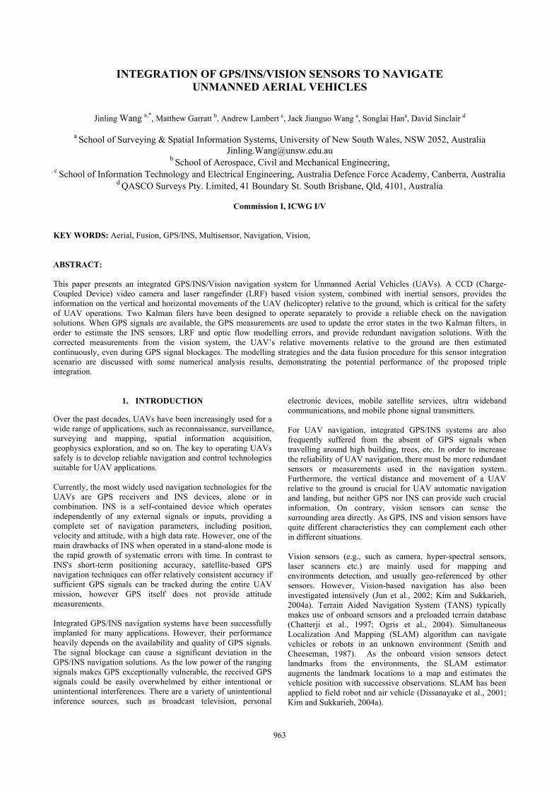
where vbxy are the horizontal translation velocities; Ωxy is the optical flow measurement of angular rate; φxy at two horizontal axis; rotation rates; rgz is the LRF measurement of the relative height from the ground. The integration flow chart is shown in Figure 1.
+
_Gyro Rates
Laser range
Optical Flow Initial
platform attitude
Σ
Relative Velocity and Height Estimation
Figure 1. Vision based navigation flow chart There are several error sources in this model. The height from the LRF may contain a small fixed offset (up to 10cm) and a small scale error (<1%). Optic flow has scale errors. Gyro rates also have bias and drift. Other errors include initial attitude error and the ground slope etc. The major error sources can be estimated using the GPS measurements as discussed below.
3. INTEGRATED GPS/INS/VISION NAVIGATION
The integrated GPS/INS/vision navigation system flow chart is shown in Figure 2. Two Kalman filters (KF) are employed in the system.
P V A
Sensors errors correction
DGPS GPS/INS 24 states -KF1 Kalman filter
Position
IMU
INS/GPS navigation
Sensors error correction
LRF
OF
Relative velocity and height Vision/gyro/GPS
navigation
GPS/Vision sensor 4 states -
KF2 Kalman filter
DGPSVelocity
Gyros
( )ϕ= Ω − ×b x y x y x y g zv rFigure 2. Integrated GPS/INS/vision system flow chart
964
The International Archives of the Photogrammetry, Remote Sensing and Spatial Information Sciences. Vol. XXXVII. Part B1. Beijing 2008
When GPS signals are available, precise GPS positioning results are used to update the error states in the Kalman filter (KF1) of 24 states, to estimate the INS errors and to provide navigation solutions. At the same time, the GPS derived velocity is used in a second Kalman filter (KF2) of 4 states to estimate the LRF and optic flow modelling errors. The corrected measurements from the gyro, LRF and optic flow are processed by the integrated INS/Vision navigation algorithm introduced in Section 2, which estimates horizontal velocity and height above the ground. During GPS outages, the measurements form LRF, and optic flow and gyro are processed continuously to get navigation solutions, which are independent from the GPS/INS solutions. 3.1 Integrated GPS/INS Navigation
The operation of the KF relies on the proper definition of a dynamic model, an observation model and a stochastic model (Brown and Hwang, 1997). While the observation model establishes the relationship between the observations and the states to estimated, the dynamic model describes the propagation of system states over time. The stochastic model describes the stochastic properties of the system process noise and observation errors. (2) (3) where x k is the (n×1) state vector, Φk is the (n×n) transition matrix, zk is the (r×1) observation vector, Hk is the (r×n) observation matrix. wk and vk are the uncorrelated white Gaussian noise. The 24 (8x3) Kalman filter error states are:
[ ]= TGI Nav Acc Gyro Grav Antx X X X X X
(4) where
[ , , , , , , , ,Nav N E D N E D N E Dr r r v v v ]δ δ δ δ δ δ δψ δψ δψ=x [ , , , , ,Acc bx by bz fx fy fz= ∇ ∇ ∇ ∇ ∇ ∇x ]
[ , , ]Gyro bx by bzε ε ε=x
(5) [ , ,Grav N E Dg g g ]δ δ δ=x [ , ,Ant x ]y zl l lδ δ δ=x
The following complete terrestrial INS psi-angle error model is adopted in the system: (6)
The observation vector z includes δrN, δrE, δrD.
3 3 3 21( ) [ ] [ 0 ] ( ) (× ×= − = +TINS GPS GIz t P P I x t v t)
]
(7) where PINS and PGPS are the INS and GPS measured positions, respectively. 3.2 Modelling Error Estimation for Vision Sensors
As mentioned in Section 3.2, there are several error sources in the model expressed by Equation (1), for calculating the platform’s horizontal velocity. The height from the LRF contains a fixed offset and a scale error. Optic flow has scale errors in two directions. Therefore, a Kalman filter is designed to estimate these errors as four states:
[ , , ,LOF b f fx fyδη δη δω δω=x
(8) where δηb and δηf are the LRF fixed offset and the scale error, respectively; δωfx and δωfy are the optic flow scale errors at x axis and at y axis, respectively. The dynamic model of these four error states is treated as zero-mean Gaussian white noise as follows:
(9)
The observation vector z includes δvN and δvE.
2 4 2 1
( ) [V ] [ ] ( ) ( )× ×
= −= +
H H TLOF LOF GPS
LOF
z t VH x t v t
(11)[ (1 ) ] ( ) (1 )
(10)
where VH
INS and VHGPS are the vision and GPS measured
horizontal velocities, respectively. According to Equation (1), and the four error parameters listed in Equation (8), the optical flow and LRF navigation error model is derived as:
where ε is the bias introduced by the ground slant and other errors. The Kalman filter error model can then be derived as: (12)
ω ϕ η η ε= Ω × − − × − × − +gxy xy fxy xy gz b f
( ) (1 )
[ (1 ) ][(1 ) ( ) ]
v r
δ η η δω
ω ϕ η δη η δη
= − × − +
Ω × − − − + −gxy gz b f fxy
xy fxy xy f b gz b fr
1+k k k k
v r
= Φx 1 1− − −x w
k= +k kz kH x v
x& LOF LOFw
δ ( )ie in
en
in
r δω ω δ δψ δ
δ ω δω δψ ε
= − + × − × + + ∇= − × +
= − × +
v v f gr v
&
&
&δψ
=
965
The International Archives of the Photogrammetry, Remote Sensing and Spatial Information Sciences. Vol. XXXVII. Part B1. Beijing 2008
Therefore the H2x4 in Equation (10) is (13) The stochastic model of the Kalman filter and the parameters for its tuning are designed according to the sensors’ specifications and the system configuration in the field tests.
4. SYSTEM CONFIGURATION
4.1 UAV (Helicopter) Platform
Experiments were conducted on an RMAX unmanned helicopter manufactured by Yamaha. It has 30kg payload with endurance of approximately one hour, and comprising a conventional helicopter design with a single main rotor and a single tail-rotor for anti-torque compensation. An autopilot system is devised for conducting closed loop experiments, in which a control by telemetry approach is taken. The sensor information is sent to a ground computer using a radio link, which processes the sensor information, calculates corresponding control inputs and sends these back to the helicopter via another radio link. An onboard PC104 computer based on the Pentium III chipset is for vision processing (Garratt, 2007). 4.2 Sensors
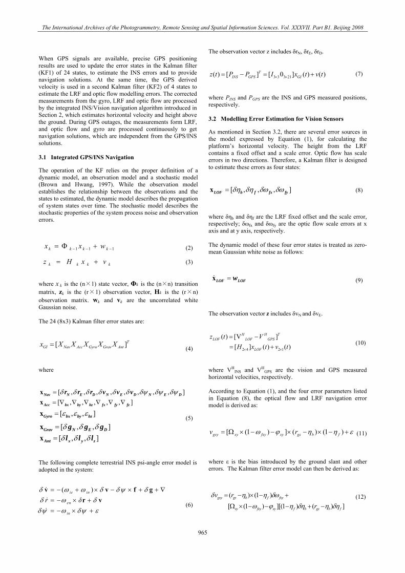
The sensors onboard the helicopter includes DGPS, INS magnetometer, LRF and CCD camera (imaging payload). Their locations are indicated in Figure 3. The data collected for the proposed integrated GPS/INS/Vision navigation system are listed in Table 1.
Figure 3. UNSW@ADFA RMAX in flight
Sensors
Data Rate
Parameters
Accuracy
INS (IMU700CB)
50 Hz
p q r (deg/s) ax ay az
Gyro: Scale <2%,Bias <20deg/hr; Acce: Scale <1%
(m/s2) Bias<12mg, DGPS (Novatel RTK)
20 Hz
N, E, Alt (m); Vxy, Vz (m/s)
~2 cm ~0.05 m/s
Optic Flow
50 Hz
Ωx Ωy
(deg/s)
Scale <2%
LRF
25 Hz
LR (m)
scale error <1% offset <10cm
2 4
[ (1 ) ](1 ) [ (1 ) ](1 )[ (1 ) ]( ) [ (1 ) ]( )
( ) (1 ) 00 ( ) (1
ω ϕ η ω ϕ ηω ϕ η ω ϕ ηη η
η η
×
Ω × − − − Ω × − − −⎡ ⎤⎢ ⎥Ω × − − − Ω × − − −⎢ ⎥=⎢ ⎥− × −⎢ ⎥− × −⎢ ⎥⎣ ⎦
Tx fx x f y fy y f
x fx x gz b y fy y gz b
gz b f
gz b f
r rH
rr )
Table 1. Data collected for the integrated navigation system An analogue Sony CCD camera is used as the image sensor. The camera outputs a PAL standard composite video signal which is captured by the frame grabber. The inertial sensors for the RMAX were pre-fitted with an isolation system, including three gyroscopes and three accelerometers with orthogonal axes. Highly accurate carrier phase DGPS measurements were available to provide a monitoring system to record the helicopter motion during closed loop. Novatel OEM4-G2L GPS cards are mounted adjacent to the RMAX flight computers. The OEM4 cards are used with differential corrections from a nearby base station fitted with another OEM4 card. The card operates in a Real-Time Kinematic (RTK) positioning mode; to provide 20Hz position and velocity with an accuracy of 1-2cm. Helicopters are dynamically unstable and require constant control inputs to prevent them from diverging from a level-flying attitude. Accurate knowledge of attitude (pitch, roll and yaw) is therefore vital to robust control. The RMAX helicopter is fitted with an in-house system for attitude determination (Garratt, 2007).
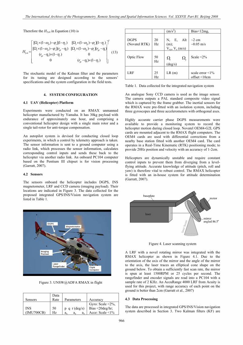
Figure 4. Laser scanning system A LRF with a novel rotating mirror was integrated with the RMAX helicopter as shown in Figure 4.1. Due to the orientation of the axis of the mirror and the angle of the mirror to the axis, the laser traces an elliptical cone shape on the ground below. To obtain a sufficiently fast scan rate, the mirror is spun at least 1500RPM or 25 cycles per second. The rangefinder and encoder signals are read into a PC104 with a sample rate of 2 KHz. An AccuRange 4000 LRF from Acuity is used for this project, with range accuracy of each point on the ground is better than 2cm (Garratt et al., 2007) 4.3 Data Processing
The data are processed in integrated GPS/INS/Vision navigation system described in Section 3. Two Kalman filters (KF) are
966
The International Archives of the Photogrammetry, Remote Sensing and Spatial Information Sciences. Vol. XXXVII. Part B1. Beijing 2008
employed in the system. The DGPS measurements are used to update the error states in both the 24 state Kalman filter KF1, to estimate the INS errors and to provide navigation solutions. At the same time the 4 state Kalman filter KF2 estimates the LRF and optic flow modelling errors. INS drift error is corrected by the DGPS to get high accuracy hybrid navigation solutions, through KF measurement updates. The CCD camera acquires texture information for optical flow measurements. The LRF measures the relative altitude to the ground which is used for the relative horizontal movement combined with the optical flow and gyro angle rate measurements. The data fusion algorithms are implemented in real-time processing mode. As shown in Table 1, the sensors have different data rates. It is necessary to select proper data rates for the two Kalman filters, considering the data availability and the required data rates (50 Hz) of navigation solutions, horizontal velocity and height over the ground. Therefore, the data rates for the sensors used for prediction were all set to 50 Hz. The 25 Hz LRF data were extrapolated to 50 Hz based on the fact of its slow change. The data rate of the DGPS data used for the Kalman filter measurement update was set to be 5 Hz.
5. TEST RESULTS
The field test data from the proposed GPS/INS/Vision navigation system were processed in two scenarios: 1) with GPS signals available during the entire mission and, 2) with simulated GPS signal outages. 5.1 Integrated GPS/INS/Vision navigation
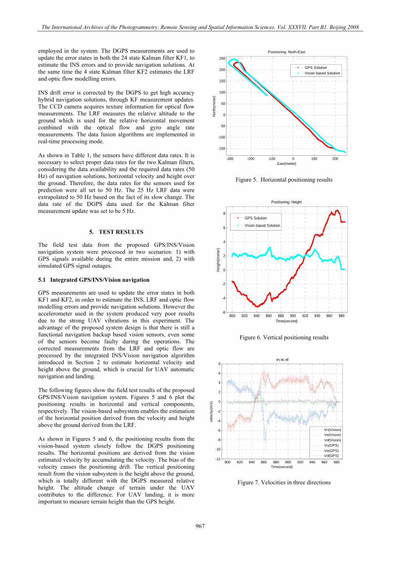
GPS measurements are used to update the error states in both KF1 and KF2, in order to estimate the INS, LRF and optic flow modelling errors and provide navigation solutions. However the accelerometer used in the system produced very poor results due to the strong UAV vibrations in this experiment. The advantage of the proposed system design is that there is still a functional navigation backup based vision sensors, even some of the sensors become faulty during the operations. The corrected measurements from the LRF and optic flow are processed by the integrated INS/Vision navigation algorithm introduced in Section 2 to estimate horizontal velocity and height above the ground, which is crucial for UAV automatic navigation and landing. The following figures show the field test results of the proposed GPS/INS/Vision navigation system. Figures 5 and 6 plot the positioning results in horizontal and vertical components, respectively. The vision-based subsystem enables the estimation of the horizontal position derived from the velocity and height above the ground derived from the LRF. As shown in Figures 5 and 6, the positioning results from the vision-based system closely follow the DGPS positioning results. The horizontal positions are derived from the vision estimated velocity by accumulating the velocity. The bias of the velocity causes the positioning drift. The vertical positioning result from the vision subsystem is the height above the ground, which is totally different with the DGPS measured relative height. The altitude change of terrain under the UAV contributes to the difference. For UAV landing, it is more important to measure terrain height than the GPS height.
-300 -200 -100 0 100 200
-150
-100
-50
0
50
100
150
200
250
East(meter)
Nor
th(m
eter
)
Positioning: North-East
GPS SolutionVision based Solution
Figure 5. Horizontal positioning results
800 820 840 860 880 900 920 940 960 980-6
-4
-2
0
2
4
6
8
Time(second)
Hei
ght(m
eter
)
Positioning: Height
GPS Solution
Vision based Solution
Figure 6. Vertical positioning results
800 820 840 860 880 900 920 940 960 980-12
-10
-8
-6
-4
-2
0
2
4
6
8
Time(second)
velo
city
(m/s
)
vn,ve,vd
Vn(Vision)Ve(Vision)Vd(Vision)Vn(GPS)Ve(GPS)Vd(GPS)
Figure 7. Velocities in three directions
967
The International Archives of the Photogrammetry, Remote Sensing and Spatial Information Sciences. Vol. XXXVII. Part B1. Beijing 2008
800 820 840 860 880 900 920 940 960 980-60
-40
-20
0
20
40
60
80
100
120
140
Attitude
Time(second)
degr
ee
HeadingPitchRoll
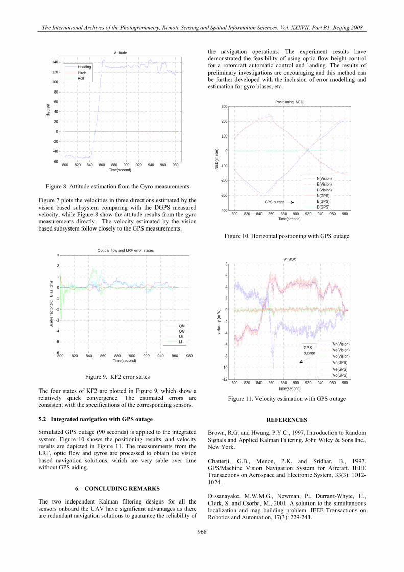
Figure 8. Attitude estimation from the Gyro measurements Figure 7 plots the velocities in three directions estimated by the vision based subsystem comparing with the DGPS measured velocity, while Figure 8 show the attitude results from the gyro measurements directly. The velocity estimated by the vision based subsystem follow closely to the GPS measurements.
800 820 840 860 880 900 920 940 960 980-6
-5
-4
-3
-2
-1
0
1
2
3
Time(second)
Sca
lre fa
ctor
:(%),
Bia
s:(d
m)
Optical flow and LRF error states
QfxQfyLbLf
Figure 9. KF2 error states The four states of KF2 are plotted in Figure 9, which show a relatively quick convergence. The estimated errors are consistent with the specifications of the corresponding sensors. 5.2 Integrated navigation with GPS outage
Simulated GPS outage (90 seconds) is applied to the integrated system. Figure 10 shows the positioning results, and velocity results are depicted in Figure 11. The measurements from the LRF, optic flow and gyros are processed to obtain the vision based navigation solutions, which are very sable over time without GPS aiding.
6. CONCLUDING REMARKS
The two independent Kalman filtering designs for all the sensors onboard the UAV have significant advantages as there are redundant navigation solutions to guarantee the reliability of
the navigation operations. The experiment results have demonstrated the feasibility of using optic flow height control for a rotorcraft automatic control and landing. The results of preliminary investigations are encouraging and this method can be further developed with the inclusion of error modelling and estimation for gyro biases, etc.
800 820 840 860 880 900 920 940 960 980-400
-300
-200
-100
0
100
200
300
Time(second)N
ED
(met
er)
Positioning: NED
N(Vision)E(Vision)D(Vision)N(GPS)E(GPS)D(GPS)
GPS outage
Figure 10. Horizontal positioning with GPS outage
800 820 840 860 880 900 920 940 960 980-12
-10
-8
-6
-4
-2
0
2
4
6
8
Time(second)
velo
city
(m/s
)
vn,ve,vd
Vn(Vision)Ve(Vision)Vd(Vision)Vn(GPS)Ve(GPS)Vd(GPS)
GPSoutage
Figure 11. Velocity estimation with GPS outage
REFERENCES
Brown, R.G. and Hwang, P.Y.C., 1997. Introduction to Random Signals and Applied Kalman Filtering. John Wiley & Sons Inc., New York. Chatterji, G.B., Menon, P.K. and Sridhar, B., 1997. GPS/Machine Vision Navigation System for Aircraft. IEEE Transactions on Aerospace and Electronic System, 33(3): 1012-1024. Dissanayake, M.W.M.G., Newman, P., Durrant-Whyte, H., Clark, S. and Csorba, M., 2001. A solution to the simultaneous localization and map building problem. IEEE Transactions on Robotics and Automation, 17(3): 229-241.
968
The International Archives of the Photogrammetry, Remote Sensing and Spatial Information Sciences. Vol. XXXVII. Part B1. Beijing 2008
Garratt M.A., H.R.Pota, A.Lambert and S.Eckersley-Maslin (2007) Systems for Automated Launch and Recovery of an Unmanned Aerial Vehicle from Ships at Sea," Proceedings of the 22nd International UAV Systems Conference, Bristol UK, 16-18 April, p14.1-14.15. Garratt, M.A. and Chahl, J.S., 2003. Visual Control of an Autonomous Helicopter, 41st Aerospace Sciences Meeting and Exhibit. American Institute of Aeronautics and Astronautics, Reno, Nevada. Garratt, M.A., 2007. Biologically Inspired Vision and Control for an Autonomous Flying Vehicle. PhD Thesis, The Australian National University, Canberra, 218 pp. Huang, T.S. and Netravali, A.N., 1994. Motion and Structure from Feature Correspondences: A Review. Proceedings of The IEEE, 82(2): 252-268. Jun, M., Motokuni, I. and Shirai, Y., 2002. Toward Vision-Based Intelligent Navigator: Its Concept and Prototype. IEEE Transactions on Intelligent Transportation Systems, 3(2): 136-146. Kim, J. and Sukkarieh, S., 2004a. SLAM aided GPS/INS Navigation in GPS Denied and Unknown Environments, The
2004 International Symposium on GNSS/GPS, Sydney, Australia. Ogris, G., Gal, C.L., Wack, R. and Paletta, L., 2004. Image Based Positioning in Urban Environments Using Kalman Filtering of PCA Sensors, The 4th International Symposium on Mobile Mapping Technology (MMT2004), Kunming, China. Smith, R. and Cheeseman, P., 1987. On the Representation of Spatial Uncertainty. International Journal of Robotics Research, 5(4): 56-68. Srinivasan, M.V., 1994. An image-interpolation technique for the computation of optic flow and egomotion. Biol. Cybernetics, 71: 401-416. Tao, C.V., Chapman, M.A. and Chaplin, B.A., 2001. Automated processing of mobile mapping image sequences. ISPRS Journal of Photogrammetry & Remote Sensing, 55(5-6): 330-346. Winkler, S., Schulz, H.-W., Buschmann, M., Kordes, T. and Vasmann, P., 2004. Improving Low-Cost GPS/MEMS-Based INS Integration for Autonomous UAV Navigation by Visual Aiding, ION GPS 2004. The Institute of Navigation, Long Beach, CA USA, pp. 1069-1075.
969

The International Archives of the Photogrammetry, Remote Sensing and Spatial Information Sciences. Vol. XXXVII. Part B1. Beijing 2008
970

![Observability Analysis for the INS Error Model with GPS ...with high-quality inertial sensors [1], [8], [5]. To circumvent this problem, a set of non-inertial sensors provides additional](https://img.pdfslide.us/doc/110x75/6029f34dd4b2435f6e30e00c/observability-analysis-for-the-ins-error-model-with-gps-with-high-quality-inertial.jpg)