Embed Size (px)
Citation preview
Integration of Component-Based
Frameworks with Sensor
Modeling Languages for the
Sensor Web By
Kimia Kazemi
Thesis submitted to the
Faculty of Graduate and Postdoctoral Studies
In partial fulfillment of
The requirements for the degree of
Master of Applied Science
In
The program of Electrical and Computer Engineering
August 2010
© Kimia Kazemi, Oshawa, Canada 2010
i
I hereby declare I am the sole author of the thesis.
I authorize the University of Ontario Institute of Technology to lend the thesis to other
institutions or individuals for the purpose of scholarly research.
Kimia Kazemi
I authorize the University of Ontario Institute of Technology to reproduce the thesis by
photocopying or other means, in total or in part, at the request of other institutions or
individuals for the purpose of scholarly research.
Kimia Kazemi

ii
Abstract
The goal of this thesis is to develop an easily modifiable sensor system. To achieve this
goal SensorML (an XML based sensor language) is combined with Java Beans (a
component model language). An important part of SensorML is its process model. Each
sensor in the real world is depicted in SensorML by a process model, whereas the
connections between the sensors are shown by a process chain. This thesis presents a
translator that reads these documents and converts them to Java Beans. Through testing
the Translator is proved more efficient than the convenient Object Oriented approach.
Keywords: Sensor languages, SensorML, IEEE1451, sensor web, component based
framework, Java Beans, Unified Modeling Language.

iii
The dedication of this thesis is split in four: First and foremost to my mother, father and
brother who have always given me their best, second to my grandparents who have
supported me, third to my country, Iran, with the hope that peace and prosperity would
reign there, and last to anyone, in any country with any ethnicity and religion who never
loses hope.
iv
ACKNOWLEGEMENTS
I would like to thank my supervisor Dr. R. Liscano for his help, guidance, support and
patience throughout my thesis.
I want to thank Dr. M. Eklund for his observations, remarks and help.
I am also thankful to Dr. A. Dersingh, and all the friends that helped throughout my
research.

v
Table of Contents
Chapter 1 Introduction and Outline ................................................................................................. 1
1.1. Motivating Scenario ......................................................................................................... 1
1.2. Problem statement .......................................................................................................... 3
1.3. Thesis Contributions ............................................................................................................. 4
Chapter 2 Background and Related Work ....................................................................................... 7
2.1 Sensor Modeling Languages: ..................................................................................................... 7
2.1.1. SensorML: .............................................................................................................................. 8
2.1.2. IEEE 1451 .................................................................................................................... 12
2.1.2.1. IEEE1451 family of standards: ........................................................................................... 13
2.1.3. TransducerML: ..................................................................................................................... 14
2.1.4. Observations and Measurement (O&M): ............................................................................ 15
2.1.5. ECHONET (Energy Conservation and Home- care Network): ........................................ 16
2.1.6. Device Kit: ............................................................................................................................ 17
2.1.7. DDL (Device Description Language): .................................................................................... 18
2.1.8. Analysis of sensor modeling Languages: .......................................................................... 20
2.2. Component based frameworks ...................................................................................... 21
2.2.1. Java Beans: ........................................................................................................................... 21
2.2.2. Microsoft’s Component Object Model (COM) ........................................................... 24
2.3. Component-Based Modeling Framework for Sensors ....................................................... 25
2.3.1. Insense (A Component-Based Model and Language for Wireless Sensor Network
Applications) .............................................................................................................................. 25
2.3.2. UM-RTCOM (A Component Framework for Wireless Sensor and Actor Networks) ........ 26
2.3.3. From a UML Platform Independent Component Model to Platform Specific Component
Models ....................................................................................................................................... 27
2.3.4. V3Studio: A Component-Based Architecture Modeling Language .................................. 28
2.3.5. Building component software with COM and Eiffel ........................................................ 29
2.3.6. A Java Component Model for evolving software systems ............................................... 30
Chapter 3 A Component based design for sensor web ................................................................. 31
3.1. Overall view............................................................................................................................. 31

vi
3.2. Translator design ..................................................................................................................... 31
3.2.1. main_class ........................................................................................................................ 31
3.2.2. DOMParser_pch ............................................................................................................... 32
3.2.3. DOMParser ....................................................................................................................... 34
3.2.4. createsBean ..................................................................................................................... 35
3.3. Setting up and Making Changes to the SCT sensor system ............................................... 40
3.3.1. Creating and Modifying SensorML documents and executing SCT ........................... 41
3.3.2. Adding a new sensor (WindChill ) to the system ....................................................... 49
3.4. Using the Components created by SCT .............................................................................. 54
Chapter 4 Testing and Validation ................................................................................................... 58
4.1. The SensIV system ................................................................................................................... 58
4.2. User’s effort in changing the sensor system ........................................................................... 62
4.2.1. Results for software engineers who had knowledge of SensIV but no knowledge of the SCT
....................................................................................................................................................... 63
4.2.2. Results for software engineers who had no knowledge of SensIV or the SCT .................... 64
4.2.3. Results for software engineers who had knowledge of both SensIV and the SCT. ............. 65
4.3. Evaluating the amount of code written. ................................................................................. 66
4.3.1. Multiple instances of one kind of sensor ......................................................................... 66
4.3.2. Multiple instances and multiple types of sensors ........................................................... 67
4.4. Measuring the correctness ..................................................................................................... 67
4.5.Cohesion and Coupling ............................................................................................................ 67
4.5.1. Cohesion........................................................................................................................... 67
4.5.2. Coupling ........................................................................................................................... 68
4.6. Analysing the results ............................................................................................................... 69
Chapter 5 Comparison ................................................................................................................... 72
5.1. Insense ........................................................................................................................... 72
5.2. UM-RTCOM .................................................................................................................... 73
5.4. V3studio ......................................................................................................................... 76
5.5. COM and Eiffel ............................................................................................................... 78
Chapter 6 Conclusion and Future Work ......................................................................................... 81
6.1. Summary and Conclusion.................................................................................................... 81
6.2. Future works ....................................................................................................................... 82
vii
References ..................................................................................................................................... 83
Appendices ..................................................................................................................................... 86

viii
List of Tables Table 1. Comparison between SensorML and IEEE1451 ............................................................... 20
Table 2. Mapping SensorML to Java Beans .................................................................................... 36
Table 3.Result of the software developers' survey ........................................................................ 66
Table 4. Results of the Testings...................................................................................................... 70
ix
List of Figures
Figure 1. Typical sensor system ....................................................................................................... 2
Figure 2. Process Chain in SensorML ............................................................................................... 9
Figure 3. SensorML system with Temperature sensor .................................................................. 11
Figure 4. SensorML system with WindChill and Temperature sensors ......................................... 12
Figure 5.IEEE 1451 structure .......................................................................................................... 12
Figure 6. Relationship between TML components ........................................................................ 15
Figure 7. The structure of COM ..................................................................................................... 24
Figure 8. Class diagram of Translator ............................................................................................. 32
Figure 9. DOMParser_pch's Activity diagram ................................................................................ 33
Figure 10. DOMParser's Activity Diagram ...................................................................................... 35
Figure 11. createsBean's Sequence Diagram ................................................................................. 39
Figure 12. Example of the relationship between the created components .................................. 40
Figure 13. Creating a new SensorML instance ............................................................................... 43
Figure 14. Inserting a member in Temperature ............................................................................. 44
Figure 15. Setting the input name and uom .................................................................................. 44
Figure 16. Inserting a new Identifier .............................................................................................. 45
Figure 17. Temperature.rng ........................................................................................................... 45
Figure 18. Inserting Components in a System ............................................................................... 46
Figure 19. SysBR ............................................................................................................................. 46
Figure 20. WindChill Component ................................................................................................... 50
Figure 21. WindChill Table ............................................................................................................. 54
Figure 22. Temperature Table........................................................................................................ 55
Figure 23. SQL snapshot of Temperature Table............................................................................. 57
Figure 24.SensIV message structure .............................................................................................. 58
Figure 25. SensIV's class diagram ................................................................................................... 60
x
List of Appendices
Appendix A………………………………………………………………………………..…86
Appendix B……………………………………………………………………………….….87
Appendix C……………………………………………………………………………….….88
Appendix D…………………………………………………………………………………101
Appendix E…………………………………………………………………………………104
xi
List of Abbreviates SensorML Sensor Modelling language
DDL Device Description Language
WASP Wirelessly accessible sensor population
ECHONET Energy conservation and home care network
IEEE Institute of Electrical and Electronics Engineers
XML Extensible Markup Language
UML Unified Modelling Language
TEDS Transducer Electronic Data Sheet
O&M Observation and Measurement
TransducerML Transducer Markup Language
SCT SensorML/Component Translator CBSE Component Based Software Engineering

1
Chapter 1 Introduction and Outline 1.1. Motivating Scenario
One of the most important objectives of any software system is its modifiability. The
systems targeted in this thesis are sensor systems. A sensor system is a collection of
sensors. A sensor is an individual detector. The users of these sensor systems are
developers. An important factor when implementing sensor systems is their ease of
modification thus the objective of this thesis is to develop software for a sensor system
that is easily modifiable.
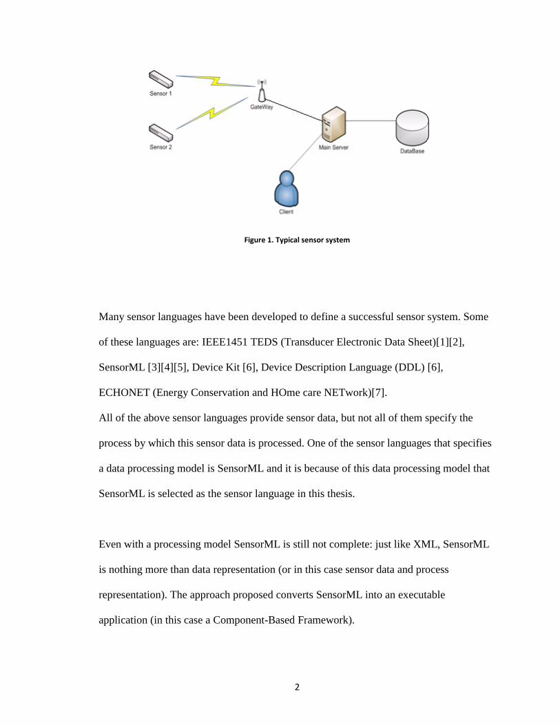
As sensors become pervasive sensor languages have become a popular option to represent
sensory data. Figure 1 shows an example of a typical sensor system. The sensor data is
received through a Gateway and it can be read by the user and stored in a Data Base. As it
will be shown in later chapters using sensor languages will result in an extensible and
discoverable system also providing the user with ease of integrity of new software
components.
2
Figure 1. Typical sensor system
Many sensor languages have been developed to define a successful sensor system. Some
of these languages are: IEEE1451 TEDS (Transducer Electronic Data Sheet)[1][2],
SensorML [3][4][5], Device Kit [6], Device Description Language (DDL) [6],
ECHONET (Energy Conservation and HOme care NETwork)[7].
All of the above sensor languages provide sensor data, but not all of them specify the
process by which this sensor data is processed. One of the sensor languages that specifies
a data processing model is SensorML and it is because of this data processing model that
SensorML is selected as the sensor language in this thesis.
Even with a processing model SensorML is still not complete: just like XML, SensorML
is nothing more than data representation (or in this case sensor data and process
representation). The approach proposed converts SensorML into an executable
application (in this case a Component-Based Framework).
3
Another problem in SensorML is its process model. The process model in SensorML can
be seen as either a benefit or hindrance for the developer depending on how you look at
it: it is a benefit when you consider the fact that other sensor languages like IEEE 1451
TEDS don‟t even have this process model part. It can also be considered as a hindrance
considering the fact that SensorML just specifies the connections between process models
without specifying the sequence in which these processes will be executed.
SensorML‟s lack of implementation and the lack of coordination between process models
motivate the development of a translator to convert SensorML into Component Based
Models. This translator will convert process models in SensorML, which specify sensors
in the real world, to components and the connections in the process chain, which specifies
the connections between the sensors, to events. The reason for the conversion of
SensorML to Component Based Models is mainly to use the event handling capability in
these models to answer SensorML‟s need for coordination. Java Beans [8] is selected as
the Component Based Model. Java Beans is a Component-Based Model that is Java
Based and abides by certain rules such as special naming patterns. The reason for this
selection is that Java Beans uses Java, which will provide platform independence. Also
Java Beans has a straight forward approach to deal with components and event handling.
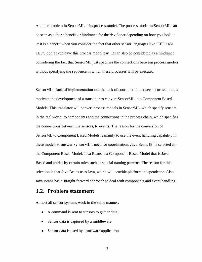
1.2. Problem statement
Almost all sensor systems work in the same manner:
A command is sent to sensors to gather data.
Sensor data is captured by a middleware
Sensor data is used by a software application.
4
Sensor data is usually stored in some sort of data base for future use.
One of the greatest challenges when developing sensor system applications is to develop
applications where changes can be implemented in them easily.
As the end users‟ comfort in using a software system is one of the goals of a successful
product thus the objective of this thesis is to develop a methodology or approach to
simplify the software design of sensor systems based on leveraging the explicit
descriptions of the sensors.
Sensor Modeling Languages are used in order to develop sensor system that are easily
modifiable. A translator is developed to automatically convert this sensor modeling
language to components. These components, which replace the software application in
the sensor systems, have the ability to insert sensor values in the data base.
1.3. Thesis Contributions
The main objectives of this research are as follows:
To describe a sensor system using SensorML documents.
To design and implement a translator to generate component based (Java Beans)
code from the SensorML documents.
To compare this approach with another functional sensor system in order to
demonstrate that the developed system is better than the conventional Object
Oriented (OO) approach in terms of measuring the impact of change in the sensor
system.
The contributions of the research reported in this thesis can be summarized as follows:
5
The design and implementation of the SensorML/Component Translator (SCT),
which is used to convert SensorML documents into executable, code (Java
Beans).
Enhancements of the current sensor system implementation. These improvements
include developing a sensor system that is easier to modify than the conventional
Object Oriented approach. An enhancement of SensorML‟s process model by
using component based frameworks. SensorML lacks proper coordination
between process models; it specifies the process models‟ connections without
mentioning anything about the time and sequence of these processes‟ execution.
Component based languages‟ events are used to solve SensorML‟s coordination
problem.
1.4. Structure of the Thesis
In this chapter, the motivating scenario for this research, the problem statement, and the
thesis contributions were presented.
The remaining chapters of the thesis are as follows:
Chapter 2: Gives the background information and related work. The first part of
this chapter goes in depth about a few sensor languages stating their pros and cons
and finally stating why SensorML was chosen as a suitable sensor language.The
second part of this chapter talks about component based framework stating their
qualities and introducing a few well known component based frameworks. The
third part of this chapter talks about Component-based frameworks for sensors.
Chapter 3: This chapter gives the design of the method implemented in the thesis.

6
Chapter 4: This chapter presents the testing and analysis of the approach taken in
this thesis with a substitute Object Oriented approach.
Chapter 5: presents the comparison between the work done in this thesis and the
related work presented in chapter 2.
Chapter 6: Presents the conclusion.
7
Chapter 2 Background and Related Work
In this chapter an in depth study of sensor languages is presented first. In the second part
of this chapter component based frameworks are analyzed. In the last part of this chapter
a study is presented with the goal of obtaining a better understanding of component-based
programming.
2.1 Sensor Modeling Languages: Several sensor languages and standards have been proposed [1][2][3][4][5][6][7][9]. Here
some of the most common standards in this area are presented.
Three of the most common sensor standards are IEEE 1451, SensorML and
TransducerML [9]. They are used with a number of standard interfaces which have been
developed by the OGC (Open Geospatial Consortium) namely: SOS (Sensor Observation
Service) [4], SPS (Sensor Planning Service) [4], SCS (Sensor Collection Service) [4] and
WNS (Web Notification Service) [4].
SensorML, TransducerML, O&M [10], SOS, SPS and WNS were developed by the OGC;
IEEE1451 was developed by NIST (National Institute of Standards and Technology) to
connect smart transducers to microprocessors and field networks. IEEE1451 defines
devices as “transducers”. Transducers can be seen as either actuators (which take an
electrical signal and commit an action) or sensors (which produce a signal proportional to
the input it receives).
The rest of the chapter is organized as follows. Section 1 gives an introduction to sensor
languages: SensorML, IEEE1451, TransducerML, O&M, ECHONET, Device Kit and
8
DDL. A comparison between SensorML and IEEE1451 is provided in the second section
followed by a study of component based frameworks in section three.
2.1.1. SensorML:
Sensor data processing is addressed by SensorML [3], [4], [5]. SensorML shows the
sensor system with a System (or a process chain). The difference between a System and a
process chain is that unlike process chains a System may have information beyond the
sensors‟ connections and reference to the process models (the process models describe the
sensors). Information like: the sensors‟ position, the calibration curve, response
parameters, the sensors‟ locations in relation to the whole system, the sensor system‟s
longitude, latitude, altitude and orientation, etc. In other words each System is a process
chain but each process chain may or may not be a System. A System is at least composed
of:
References to the process models.
Connections between process models.
A process chain is composed of sub parts called process models.
A process model itself describes the inputs and outputs and has a reference to a process
method which consists of:
A metadata or documentation part.
A Schematron part showing the I/O constraints.
A MathML part for the visualization of mathematical equations.
A reference to a coding section.
Part of the SensorML description also captures static metadata information about the
sensor like the sensor name, type, and manufacturer but the reason SensorML was chosen

9
was because of its process definition part. Figure 2 shows SensorML‟s process chain. The
intention of this figure is to show SensorML‟s different components (the process chain,
the process models, and the process methods), and the process models‟ connections inside
the process chain (these connections are shown by the arrows in Figure 2).
The physical part of SensorML is the part that is capable of describing the T
Code 1 shows an example of a temperature sensor coded in SensorML. SensorML defines
the sml XML namespace. This code shows the metadata for this sensor using the
sml:Term tag and in this case it is trying to model an MTS 310 sensor board from
Crossbow. The code also shows the sensor inputs (sml:Inputs) outputs (sml:Outputs) and
a reference link to the process method given by the sml:method tag. This particular
example has one input, “Temp1” and one output, “Temperature”.
Code 2 shows an example of the process chain (the system as a whole). The sensor
system is defined as a set of components that include references to SensorML sensor or
devices, given by the sml:component reference, and links between these components
(sml:Link). In this example the sensor system consists of only 1 component, the “Temp1”
sensor and therefore the source and destination links point to the same component.
Process Chain
Process Model A
Process
Model
Process
method
Process Model B
Process
Model
Process
method
Process Model C
Process
Model
Process
method
Figure 2. Process Chain in SensorML
10
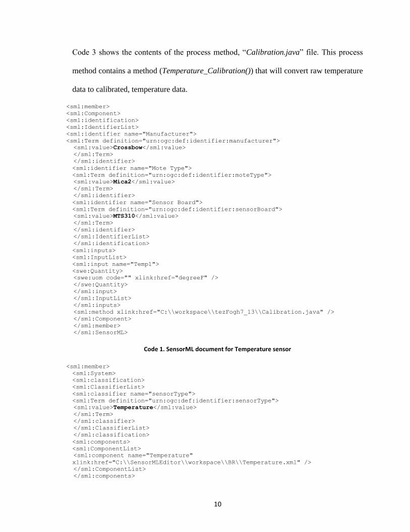
Code 3 shows the contents of the process method, “Calibration.java” file. This process
method contains a method (Temperature_Calibration()) that will convert raw temperature
data to calibrated, temperature data.
<sml:member>
<sml:Component>
<sml:identification>
<sml:IdentifierList>
<sml:identifier name="Manufacturer">
<sml:Term definition="urn:ogc:def:identifier:manufacturer">
<sml:value>Crossbow</sml:value>
</sml:Term>
</sml:identifier>
<sml:identifier name="Mote Type">
<sml:Term definition="urn:ogc:def:identifier:moteType">
<sml:value>Mica2</sml:value>
</sml:Term>
</sml:identifier>
<sml:identifier name="Sensor Board">
<sml:Term definition="urn:ogc:def:identifier:sensorBoard">
<sml:value>MTS310</sml:value>
</sml:Term>
</sml:identifier>
</sml:IdentifierList>
</sml:identification>
<sml:inputs>
<sml:InputList>
<sml:input name="Temp1">
<swe:Quantity>
<swe:uom code="" xlink:href="degreeF" />
</swe:Quantity>
</sml:input>
</sml:InputList>
</sml:inputs>
<sml:method xlink:href="C:\\workspace\\tezFogh7_13\\Calibration.java" />
</sml:Component>
</sml:member>
</sml:SensorML>
Code 1. SensorML document for Temperature sensor
<sml:member>
<sml:System>
<sml:classification>
<sml:ClassifierList>
<sml:classifier name="sensorType">
<sml:Term definition="urn:ogc:def:identifier:sensorType">
<sml:value>Temperature</sml:value>
</sml:Term>
</sml:classifier>
</sml:ClassifierList>
</sml:classification>
<sml:components>
<sml:ComponentList>
<sml:component name="Temperature"
xlink:href="C:\\SensorMLEditor\\workspace\\BR\\Temperature.xml" />
</sml:ComponentList>
</sml:components>

11
<sml:connections>
<sml:ConnectionList>
<sml:connection>
<sml:Link>
<sml:source ref="Temperature\Temp1" />
<sml:destination ref="Temperature\Temp1" />
</sml:Link>
</sml:connection>
</sml:ConnectionList>
</sml:connections>
</sml:System>
</sml:member>
</sml:SensorML>
Code 2. SensorML document of a System (Process Chain) with a Temperature sensor
public class Calibration{
public void Temperature_Calibration(){
double out = 2.5 * ((double) Temp1 / 4096) * 100 * 2. - 273;
System.out.println("Calibrated Temperature is: " + out);
}
}
Code 3. Process method Calibration.java
Figure 3 shows an example of a SensorML system with one, temperature sensor that has a
single input and a single output.
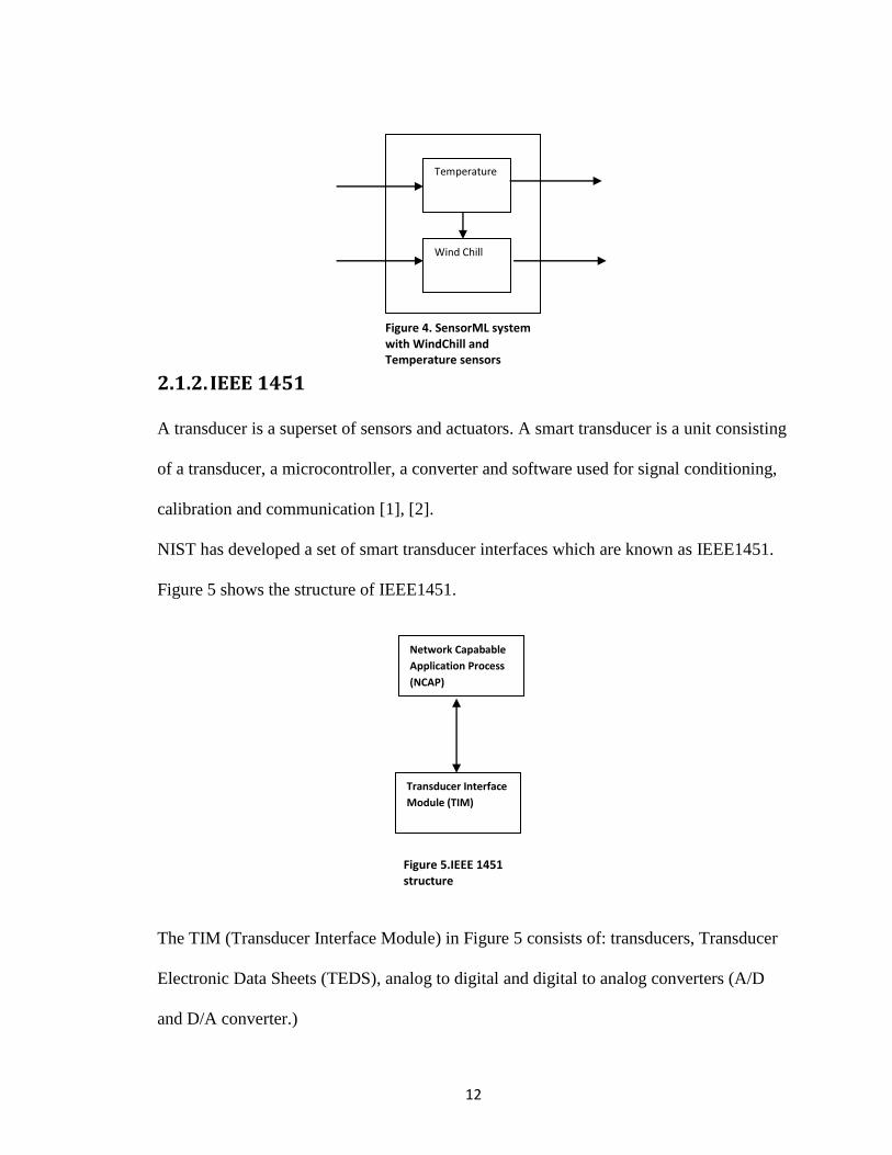
Figure 4 shows an example of another sensor system with a wind chill and a temperature
sensor. Wind chill has two inputs, temperature and wind speed. As can be seen from
Figure 4 the output of the temperature sensor provides one of the inputs to the wind chill
sensor.
Figure 3. SensorML system with Temperature sensor
Temperature
12
2.1.2. IEEE 1451
A transducer is a superset of sensors and actuators. A smart transducer is a unit consisting
of a transducer, a microcontroller, a converter and software used for signal conditioning,
calibration and communication [1], [2].
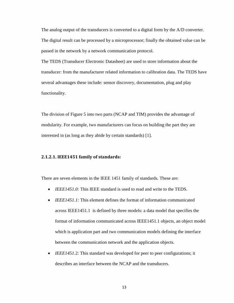
NIST has developed a set of smart transducer interfaces which are known as IEEE1451.
Figure 5 shows the structure of IEEE1451.
The TIM (Transducer Interface Module) in Figure 5 consists of: transducers, Transducer
Electronic Data Sheets (TEDS), analog to digital and digital to analog converters (A/D
and D/A converter.)
Network Capabable
Application Process
(NCAP)
Transducer Interface
Module (TIM)
Figure 5.IEEE 1451 structure
Temperature
Wind Chill
Figure 4. SensorML system with WindChill and Temperature sensors
13
The analog output of the transducers is converted to a digital form by the A/D converter.
The digital result can be processed by a microprocessor; finally the obtained value can be
passed in the network by a network communication protocol.
The TEDS (Transducer Electronic Datasheet) are used to store information about the
transducer: from the manufacturer related information to calibration data. The TEDS have
several advantages these include: sensor discovery, documentation, plug and play
functionality.
The division of Figure 5 into two parts (NCAP and TIM) provides the advantage of
modularity. For example, two manufacturers can focus on building the part they are
interested in (as long as they abide by certain standards) [1].
2.1.2.1. IEEE1451 family of standards:
There are seven elements in the IEEE 1451 family of standards. These are:
IEEE1451.0: This IEEE standard is used to read and write to the TEDS.
IEEE1451.1: This element defines the format of information communicated
across IEEE1451.1 is defined by three models: a data model that specifies the
format of information communicated across IEEE1451.1 objects, an object model
which is application part and two communication models defining the interface
between the communication network and the application objects.
IEEE1451.2: This standard was developed for peer to peer configurations; it
describes an interface between the NCAP and the transducers.
14
IEEE1451.3: This standard does the same work as the standard before only this
time instead of peer to peer configuration this is done for multi-drop
communication protocols.
IEEE1451.4: This element standard was defined for analog transducers with
analog and digital operating modes.
IEEE1451.5: This standard was defined as an interface between NCAP and
wireless transducers.
IEEE1451.6: This standard uses CANOpen network interface and it defines an
interface between the NCAP and the transducers.
IEEE1451.7: This element defines an interface between transducers and RFID
systems.
2.1.3. TransducerML: Transducers are the super sets for sensors and actuators. When receiving a message from
a transducer it is a stream of binary data; in this form it is impossible to tell what the data
means. TransducerML gives some meaning to the stream of data received. How much of
the data is used is dependent on what it is going to be done with the data. If for example
the purpose is only to display data on the screen then it is enough to know the structure of
the data but if the purpose is also to know what the sensor is measuring we also need to
know the transducer‟s or sensor‟s characteristics.TML is part of the Sensor Web
Enablement (SWE) and it is used with O&M and SensorML.
In TransducerML not only is the sensor data transmitted but also the sensor metadata is
transmitted; this is used for searching, discovering, subscribing and processing. Figure 6

15
depicts the relationships characterized by TML.
TransducerML has several similarities to SensorML the main ones being that:
TransducerML‟s encoding is XML, and its design perspective is data oriented everything
is seen as input, process and output. Howevere, unlike SensorML the basic components in
TransducerML are processes and the composite components are subjects.
2.1.4. Observations and Measurement (O&M): O&M document defines a set of ways to tie the values and the unit of measures together.
This information is encoded in an XML format.
The basic information provided by Observation includes the time of the event
(timestamp); the value of a procedure such as instrument or simulation (using); the
identification of phenomenon being sampled (observable); the association of other
features that are related to the Observation (relatedFeature); the common related features
that have fixed role such as Station or Specimen (target); the quality indicators associated
Subject
Sensor
Process/Data
Figure 6. Relationship between TML components

16
with the Observation (quality); the result of the Observation (resultOf); location
information (location) and the metadata description (metadataProperty).
2.1.5. ECHONET (Energy Conservation and Home- care
Network): This standard originated in Japan with the purpose of monitoring energy consumption. It
allows the integration of devices from multiple vendors. To get a device incorporated in
the network the vendors must provide the same interface as specified in the ECHONET
specification [6],[7].
The ECHONET device specification is a list of devices each shown as classes. The
classes properties and methods are explained in plain English.
Having a device specification which is like a big dictionary is what makes ECHONET
unscalable: if the device changes the specification and therefore the standard must
change.
The objectives of ECHONET are that: data transmission should not require rewiring of
the existing houses, it should be possible to use products from different vendors together
in a single network, Plug and Plug should be provided, low cost connections with existing
standards should be provided.
17
2.1.6. Device Kit:
The Device Kit enables the development of applications for devices when hardware-
information is unknown. Device Kit uses eclipse to generate the component to interface
with a hardware device [6].
The application interfaces with the Device Kit and the Device Kit interfaces with the
hardware.
Device Kit uses the publish/subscribe service: an application subscribes to a service and it
is notified when an event is published.
Device Kit makes use of DKML (Device Kit markup language) which is an xml file that
contains information about the devices. There exists a DKML to java generator to convert
between the DKML and java formats.
As it can be seen from the description of Device Kit; Device Kit is quite similar to the
work performed in this thesis. The similarities are the following:
Device Kit uses DKML, which is an XML file containing information about
sensors, in this thesis SensorML is uses, which is an XML file containing
information about the sensor data and processes.
There is a generator that converts DKML to java. In this work a translator is
developed that converts SensorML to Java Beans, which is Java language
following a set of patterns.
Publish/subscribe services are used in both Device Kit and the code generated by
the translator in this thesis.
18
A big difference between SensorML and Device Kit is that in SensorML the hardware
information is not unknown and it is embedded inside the process model where as Device
Kit provides a platform for applications where hardware information is unknown.
2.1.7. DDL (Device Description Language):
DDL was first developed in the University of Florida. It assumes devices have no
networking capabilities and they connect to applications via motes. Therefore, DDL only
focuses on device to device interfaces [6].
In DDL a device consists of information on the properties (which provides information
about the device such as the device‟s vendor, its purpose, etc), internal mechanisms
(which are related to the operation of the device and hidden from the outside world),
interfaces (which are links between internal mechanisms and the external world).
DDL classifies devices into: sensors (which provide users with inputs), actuators (which
accept outputs from users), and complex devices (which do both of the aforementioned
tasks.)
Sensor Services are subdivided into three parts:
1. Physical sensor service: a service which gets an input from a single
source.
2. Basic Virtual Sensor service: a service that accepts input from multiple
sources with the same unit.
3. Derived Virtual sensor service: a service that accepts input from multiple
sources with different units.

19
Each DDL file descriptor contains information needed for the discovery of the device like
the device name and its model; it also contains the description of the device‟s operations.
Here, the inputs are known as signals and the outputs are known as readings.
The DDL schema will define constraints on the DDL document. This is enforced by the
DDL validity checker.
The DDL element which is the root element of the DDL consists of a sensor, an actuator
and a device. Each sensor consists of a description and an interface. The description part
of the sensor has the descriptive information about the sensor, whereas the Interface part
of the sensor consists of the signals and the readings.
20
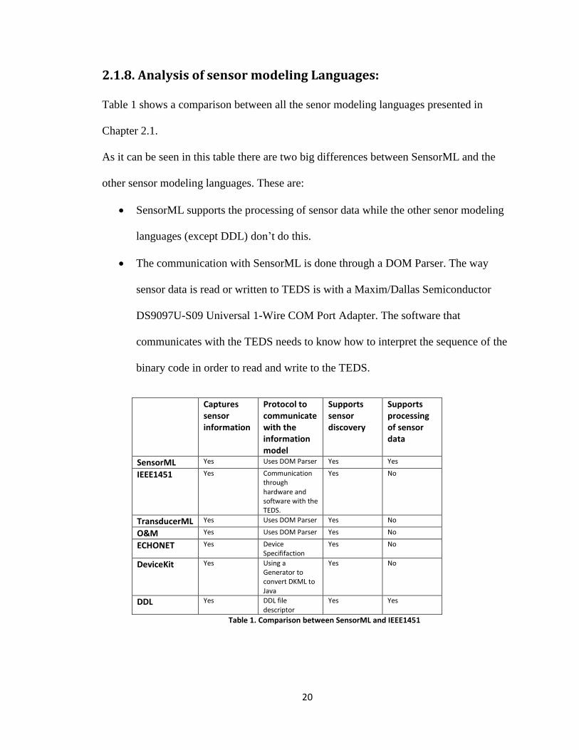
2.1.8. Analysis of sensor modeling Languages:
Table 1 shows a comparison between all the senor modeling languages presented in
Chapter 2.1.
As it can be seen in this table there are two big differences between SensorML and the
other sensor modeling languages. These are:
SensorML supports the processing of sensor data while the other senor modeling
languages (except DDL) don‟t do this.
The communication with SensorML is done through a DOM Parser. The way
sensor data is read or written to TEDS is with a Maxim/Dallas Semiconductor
DS9097U-S09 Universal 1-Wire COM Port Adapter. The software that
communicates with the TEDS needs to know how to interpret the sequence of the
binary code in order to read and write to the TEDS.
Captures sensor information
Protocol to communicate with the information model
Supports sensor discovery
Supports processing of sensor data
SensorML Yes Uses DOM Parser Yes Yes
IEEE1451 Yes Communication through hardware and software with the TEDS.
Yes No
TransducerML Yes Uses DOM Parser Yes No
O&M Yes Uses DOM Parser Yes No
ECHONET Yes Device Specififaction
Yes No
DeviceKit Yes Using a Generator to convert DKML to Java
Yes No
DDL Yes DDL file descriptor
Yes Yes
Table 1. Comparison between SensorML and IEEE1451

21
As was stated in Chapter 1 main goal of this work is to: convert sensor languages into
executable, component based programs.
SensorML is selected as the sensor language because with the exception of DDL it is the
only sensor modeling language that specifies the execution process of a sensor system.
This is very important in determining the flow in component based design. SensorML is
chosen instead of DDL because SensorML is a better known standard and because the
connections in the process chain of SensorML are easily mapped into Component-Based
Frameworks, which are the second part of this work.
2.2. Component based frameworks
Component Based Software Engineering (CBSE) [11],[12] was first introduced in the
1990s and is based upon building reusable software components. Java Beans is an
example of a component based framework which is created using the Java language [8].
One of the qualities of Component-Based Frameworks which makes them especially
interesting in this thesis is the event handling, which will be used to implement the
connections between the processes.
Now several Component-Based Frameworks will be discussed.
2.2.1. Java Beans: Java Beans are software components that abide by a certain number of rules such as
special naming patterns.
Introspection (which is the ability to extract a Bean‟s properties, method and events),
properties (which are the behaviors of Beans), Event handling (the capability of the Beans
to communicate with each other), persistence (the ability to save and restore Beans‟
properties), methods (which are like normal Java methods) are the core Beans‟ concepts.

22
In this section some of the most important features of Java Beans that are exclusive to
Java Beans like event handling, introspection and persistance are explained.
The connections in the process chain can be modeled in different manners: one of them is
to provide a coordinator which will facilitate the communication between the process
models; the other is by using events. In this design connection by means of events is used.
Java Beans uses three classes when dealing with events: PropertyChangeSupport (which
contains three methods: add/removePropertyChangeListener and firePropertyChange),
PropertyChangeEvent (which contains three methods getNewValue, getOldValue and
getPropertyName), PropertyChangeListener (which is an interface supplying one
method, propertyChange.
Events are addressed in Java Beans by using bound properties. Bound properties are
properties that transmit notifications when changes occur to event handlers.
A java bean that has bound properties must keep a list of propertyChangeListeners. As
such the bean implements the propertyChangeListener interface. When we implement this
interface we override the propertyChange method that specifies what should happen once
the property changes.
The class PropertyChangeSupport implements methods that add and remove
PropertyChangeListeners. Since adding and removing PropertyChangeListeners is
needed the Bean will have a PropertyChangeSupport attribute.
The firePropertyChange method that is called within the setter method sends a
PropertyChangeEvent (that lets us see the old and new value of the changed attribute and
the name given to it) to Java classes which implement the PropertyChangeListener.

23
Introspection is the process by which properties, methods and events in a class are
exposed. By following a set of basic conventions (such as each property has to have a set
and get method and these set and get methods are composed of the name set or get plus
the name of the property). Code 4 shows an example of introspection and its output for
the Temperature sensor. The Temperature sensor has one input called Temp1.
A person might need to provide more descriptive information of the java bean. In this
case they will use the BeanInfo class which involves more work but is sometimes
necessary.
import java.beans.BeanInfo;
import java.beans.Introspector;
import java.beans.IntrospectionException;
import java.beans.PropertyDescriptor;
public class Temperature
{
double Temp1;
public double getTemp1()
{
return Temp1;
}
public void setTemp1( double x )
{
Temp1=x;
}
}
Code 4. Example of a class (Temperature) that is going to be tested for introspection
import java.beans.BeanInfo;
import java.beans.IntrospectionException;
import java.beans.Introspector;
import java.beans.PropertyDescriptor;
24
public class Test {
public static void main( String[] args )
throws IntrospectionException
{
BeanInfo info = Introspector.getBeanInfo( Temperature.class,
Object.class );
for ( PropertyDescriptor pd : info.getPropertyDescriptors() )
System.out.println( pd.getName() );
}
}
Code5. Example of testing Introspection for class Temperature
Persistence is the mechanism by which any bean can store its state. It gets converted in a
data stream and saved; any program can retrieve this state by deseralizing it. It is also
possible to serialize parts of the bean this is done by excluding the fields you don‟t want
serialized by using the keyword transient.
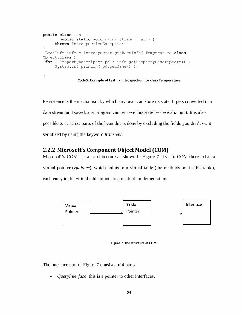
2.2.2. Microsoft’s Component Object Model (COM) Microsoft‟s COM has an architecture as shown in Figure 7 [13]. In COM there exists a
virtual pointer (vpointer), which points to a virtual table (the methods are in this table),
each entry in the virtual table points to a method implementation.
The interface part of Figure 7 consists of 4 parts:
QueryInterface: this is a pointer to other interfaces.
Virtual
Pointer
Interface Table
Pointer
Figure 7. The structure of COM

25
AddRef: to assign memory. (interfaces are a pointer to a block of memory)
Release: release memory.
Other methods
COM has been implemented both across C and Java platform.
There are several problems with COM:
COM was created because of MS Office product‟s need to interact with each
other.
When COM is used with Java it only supports a version of Java implemented in
Microsoft Windows thus it undermines a very strong point in Java which is its
ability to work across multiple platforms.
From this thesis‟ point of view COM needs to be able to use XML format (for the
SensorML documents) and at the moment COM doesn‟t seem able to do this.
2.3. Component-Based Modeling Framework for Sensors
In this section a discussion of the related work is presented. Specifically, we focus on the
application of Component-Based Frameworks with sensor modeling languages. The work
presented in this part is closely related to the approach taken in this thesis. A comparison
of the work presented in this section and this thesis is presented in chapter 5.
2.3.1. Insense (A Component-Based Model and Language
for Wireless Sensor Network Applications)
Insense is a component based language for wireless sensor networks developed by Alan
Dearle et. Al [14][15]. Insense is an implementation of a component diagram. A
component has an input channel and an output channel with which it can connect to other
26
components. The components‟ channels have primitive types. Insense is written using
Java and it creates a C source code.
To define a component in Insense two things have to be defined: an interface and an
implementation of that interface. In the interface the type of the input and output channel
is defined. The implementation of the interface has three parts: the variables of the
component, the constructor and the behavior of the component. The constructor is used to
initialize the component; the behavior is the part of the component that runs until it is
stopped by either the component itself or another component by using the keyword stop.
Four operations (send, receive, connect, and disconnect) can be performed on the
channels. Each channel consists of two half channels each of which have five parts (a
buffer for the type storage, Ready and nd_received for communication purposes, a binary
semaphore called mutex, which provides mutual exclusion on the channel, a list of
connections that are pointers to the half channel).
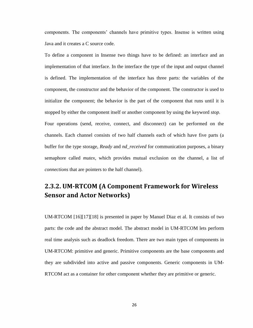
2.3.2. UM-RTCOM (A Component Framework for Wireless
Sensor and Actor Networks)
UM-RTCOM [16][17][18] is presented in paper by Manuel Diaz et al. It consists of two
parts: the code and the abstract model. The abstract model in UM-RTCOM lets perform
real time analysis such as deadlock freedom. There are two main types of components in
UM-RTCOM: primitive and generic. Primitive components are the base components and
they are subdivided into active and passive components. Generic components in UM-
RTCOM act as a container for other component whether they are primitive or generic.

27
The generic components consist of three parts: an interface part which specifies the
provided and required interfaces, a part which includes the implementation part and a part
that specifies the published and subscribed events.
In UM-RTCOM active components indicate the execution flow and they are used to
interact with other components. Passive components do not specify any execution. They
are rather used for mutual exclusion and they allow the use of shared resources in the
system.
In UM-RTCOM there are three synchronization primitives: wait (which is used in active
components and makes a component wait until an event occurs), call (which is used to
call methods) and raise (which is used to trigger events). The three synchronization
primitives are the only way to communicate with other components.
UM-RTCOM has three features which makes it suitable for use in real time
environments. These are: configuration slots (which is the capability of manipulating
certain parameters, this results in reusability of the software), Real time constraints
specification (using this feature the user could specify the kind of real time aspect they
are interested in; for example a user might be interested in completing a task by a certain
deadline), real time analysis.
2.3.3. From a UML Platform Independent Component
Model to Platform Specific Component Models
This work is done by Tewfik Ziadi et al [19]. In this paper Tewfik Ziadi et al. present a
method for mapping UML to component based languages like Enterprise Java Beans
(EJB) and Corba Component Model (CCM).
The three main parts of a component in this paper are:
28
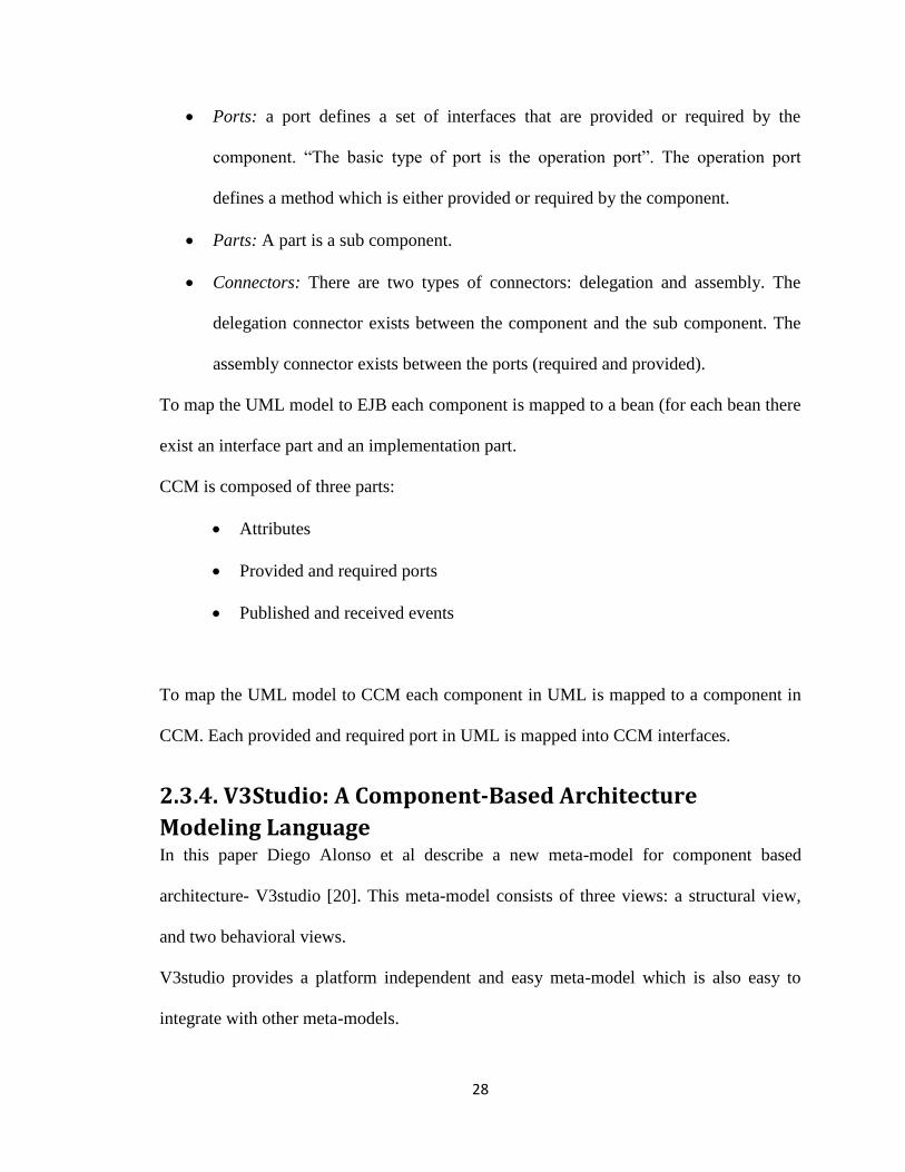
Ports: a port defines a set of interfaces that are provided or required by the
component. “The basic type of port is the operation port”. The operation port
defines a method which is either provided or required by the component.
Parts: A part is a sub component.
Connectors: There are two types of connectors: delegation and assembly. The
delegation connector exists between the component and the sub component. The
assembly connector exists between the ports (required and provided).
To map the UML model to EJB each component is mapped to a bean (for each bean there
exist an interface part and an implementation part.
CCM is composed of three parts:
Attributes
Provided and required ports
Published and received events
To map the UML model to CCM each component in UML is mapped to a component in
CCM. Each provided and required port in UML is mapped into CCM interfaces.
2.3.4. V3Studio: A Component-Based Architecture
Modeling Language
In this paper Diego Alonso et al describe a new meta-model for component based
architecture- V3studio [20]. This meta-model consists of three views: a structural view,
and two behavioral views.
V3studio provides a platform independent and easy meta-model which is also easy to
integrate with other meta-models.
29
V3studio can be seen as rather constrained form of UML. V3studio defines three models:
one for the component view, one for the state machine and one for the activity diagram.
These models are implemented used the graphical model framework (GMF). In order to
depict component behaviors in V3studio two diagrams are used: state diagrams and
activity diagrams. State diagrams show what happens when an event occurs in a system,
whereas activity diagrams describe the data flow. In V3studio a state diagram is defined
for the system and for each state an activity diagram should be defined. Components can
communicate with each other via portlinks.
There are two types of components in V3studio: simple components and complex
components. Complex components contain simple ones and their relationship inside
them.
2.3.5. Building component software with COM and Eiffel This approach uses Microsoft‟s Component Object Model (COM) standard with an object
oriented model (Eiffel) [13]. COM is a standard to deal with components. In COM there
exists a virtual pointer (vpointer) and the vpointer points to a virtual table where the
methods are and each entry in the virtual table points to a method implementation. The
virtual tables and pointer can be comparable to the process models which contain
references to the process method where the code is stored.
In COM one vpointer corresponds to one interface hence there is no multiple inheritance
capability in COM. There is a super interface for all COM components called the
IUnknown this is a clear difference with the work shown in this thesis because as
explained before interfaces are a level of abstraction which is not provided in this work.

30
IUnknown has three methods: QueryInterface, AddRef, Release. AddRef and Release are
to keep count of the total references to a component. QueryInterface is to access another
interface.
COM has an Interface Definition Language (IDL), it consists of three parts: a part
specifying that this is a COM declaration, another part showing a unique identifier, and
the third part is the IUnknown interface. Besides the COM IDL there exists COM classes
which implement the interfaces.
COM provides the ability of dealing with distributed components by using Remote
Process Calls (RPC). COM lets component execute in both multi thread and not thread
aware systems. Type libraries enable the discovery of interfaces. Using type libraries a
person can find out about the interfaces, interfaces‟ methods and data type.
2.3.6. A Java Component Model for evolving software systems
The Java Component Model (JCM) [21] is another generic component development
environment.
A component model in JCM consists of three parts:
A specification model: defines the services provided and required by the component
The implementation model: defines the implementation
And the connector model: defines the connection between the components.
Overall generic component-based development environments like UM-RTCOM and JCM
require a significant amount of customization in order to take advantage of sensor
specification languages like SensorML.
31
Chapter 3 A Component based design for sensor web In this chapter a comprehensive design overview of SCT (SensorML/Component
Translator) is given, this section is followed by a section on how to set up and implement
changes to the sensor system in this thesis, and another section on how to interact with the
components created by SCT.
3.1. Overall view
In a typical sensor system the Main Server (MS) sends a data acquisition command and
the sensors send data to the MS; the data gets stored in a DB. If a client needs to read the
data from the DB it will send a request to the MS and the MS will read the data from the
DB.
3.2. Translator design This section provides the translator design using class, sequence and activity diagrams.
3.2.1. main_class This class is the main class where the rest of the classes are executed from.
This class has the following attributes:
dpch: this attribute is of type DOMParser_pch which store variables related to the
process chain such as a reference to the process models and the connection
between the process models.
d: this attribute is of type DOMParser which store variables related to the process
models such as the input and output and the type of the input and output and a
reference to a source code outside SensorML. (This part denotes the process
method).
32
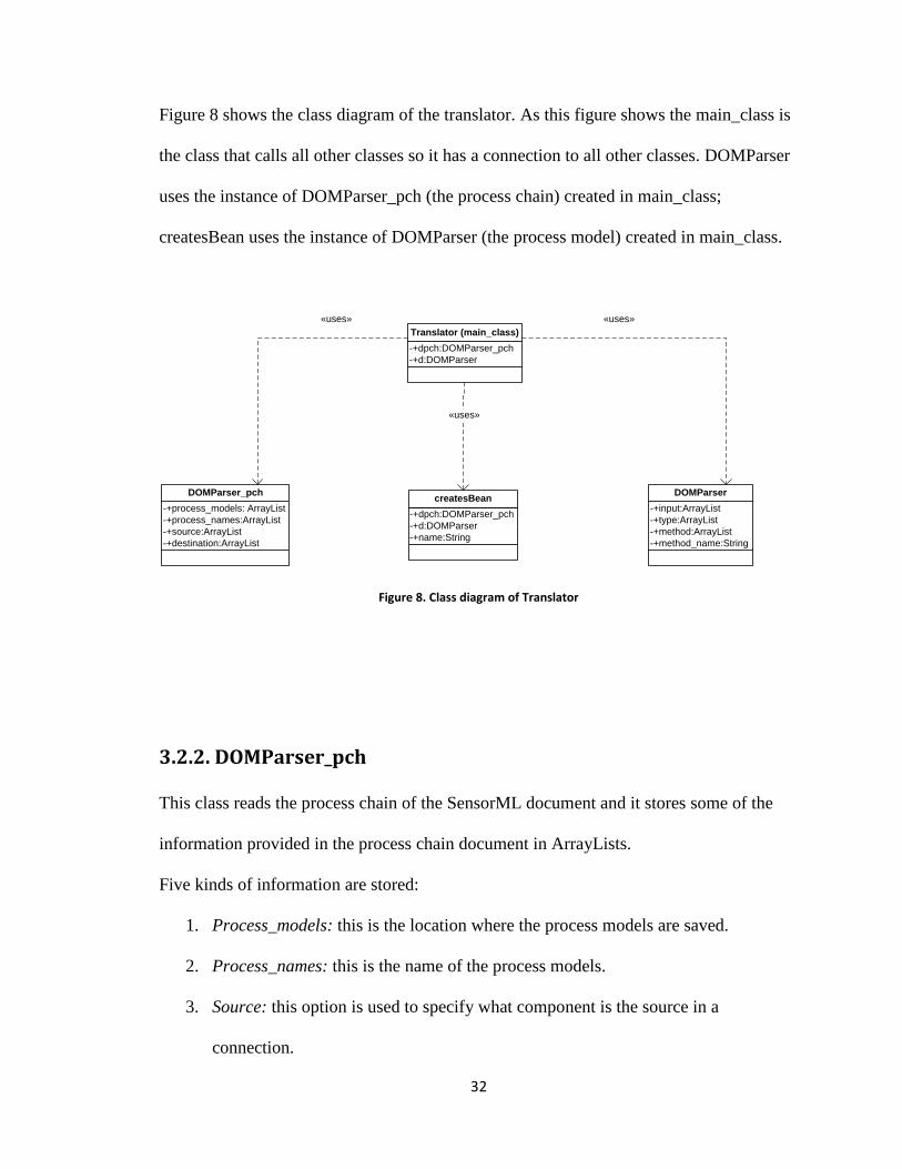
Figure 8 shows the class diagram of the translator. As this figure shows the main_class is
the class that calls all other classes so it has a connection to all other classes. DOMParser
uses the instance of DOMParser_pch (the process chain) created in main_class;
createsBean uses the instance of DOMParser (the process model) created in main_class.
-+dpch:DOMParser_pch
-+d:DOMParser
Translator (main_class)
-+process_models: ArrayList
-+process_names:ArrayList
-+source:ArrayList
-+destination:ArrayList
DOMParser_pch
-+dpch:DOMParser_pch
-+d:DOMParser
-+name:String
createsBean-+input:ArrayList
-+type:ArrayList
-+method:ArrayList
-+method_name:String
DOMParser
«uses»
«uses»
«uses»
Figure 8. Class diagram of Translator
3.2.2. DOMParser_pch
This class reads the process chain of the SensorML document and it stores some of the
information provided in the process chain document in ArrayLists.
Five kinds of information are stored:
1. Process_models: this is the location where the process models are saved.
2. Process_names: this is the name of the process models.
3. Source: this option is used to specify what component is the source in a
connection.

33
4. Destination: this option is used to specify what component is the destination in a
connection.
Figure 9 shows the activity diagram of this class. As it can be seen this diagram after
having parsed the SensorML document DOMParser_pch stores information about the
process models‟ location, source and destination.
Figure 9. DOMParser_pch's Activity diagram

34
3.2.3. DOMParser
This class reads the process models of the SensorML document and it stores some of the
information provided in the process models documents in ArrayLists. Five kinds of
information are stored:
1. Input: this is the name of the input values to the process models.
2. Type: this is the unit of measure of the input values
3. Method: this is the location the method in the process model is stored.
4. Method_name: this is the name of the method.
5. Metadata information like: the sensor‟s manufacturer, the sensor Board,
the sensor type, and the model number.
Figure 10 shows the activity diagram of this class. As it can be seen this class after having
parsed the SensorML document this class stores the information about the process
model‟s inputs, types and a reference to a java source code where the process method is.

35
Figure 10. DOMParser's Activity Diagram
3.2.4. createsBean
The class createsBean maps the SensorML documents into Java Beans, so this class is the
class that does the translation.
There are two kinds of Beans:
Normal Beans: which are the equivalents of process models.
A connector Bean: which is the equivalent of a process chain.
Each process model (sensor) gets converted to a normal Java Bean; so a normal Bean
contains information about the sensor‟s inputs and outputs, the inside process of a sensor
and the metadata of a sensor (like the mote type, the sensor type, the sensor board and the
manufacturer). The process method contains information such as the calibration formula
36
and it is mapped to part of the Bean; the process chain shows the connection between the
components and is mapped into events.
The connections in the process chain can be modeled in different manners: one of them is
to provide a coordinator which will facilitate the communication between the process
models. The other is by using events.
Normal Beans can communicate in two different ways: one way would be to connect the
Normal Beans together without the use of a third component. Another way (which is the
way done in this thesis) is to use a third component to connect these Beans together. The
reason this approach was taken was because of its similarity to SensorML architecture:
process models could be mapped into Beans and the process chain could be mapped into
the connector Bean.
An event is an action that when it happens it triggers a change of state. Classes that are
interested in events register for events using an event listener and when that event occurs
they are notified that an event has occurred. The way Java Beans deals with this is by
using the class PropertyChangeSupport. Any class that wants to receive events registers
to PropertyChangeListener. The listeners will be invoked only when there is a call to
the firePropertyChange. FirePropertyChange is called inside each setter operation
and it stores the old and new value of that attribute and the given name of that attribute.
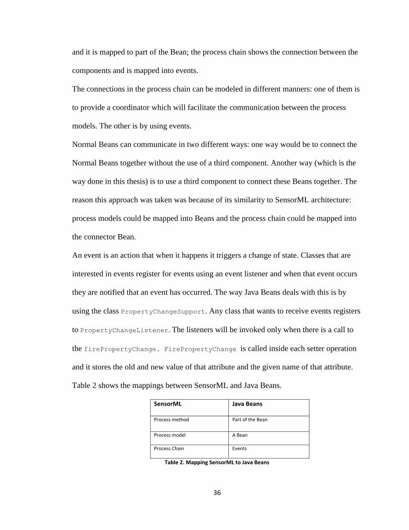
Table 2 shows the mappings between SensorML and Java Beans.
SensorML Java Beans
Process method Part of the Bean
Process model A Bean
Process Chain Events
Table 2. Mapping SensorML to Java Beans

37
This class creates a component. This class is in fact the translator which is between the
SensorML file and the components.
This class needs three kinds of information to function:
1. dpch: this is an instance of the DOMParser_pch and provides the
information of the process chain.
2. d: this is an instance of the DOMParser and provides the information of
the process model.
3. name: this is the process models or the components name.
Figure 11 shows the sequence diagram of this class. In this diagram out and file are the
FileWriter and the FileReader; the FileWriter is used to create the output files, which will
be the Beans, the FileReader will be used to read the process method. StringTokenizer is
used in the process chain to separate the name of the component from the component‟s
attribute name. For example in code 6 StringTokenizer will separate Temperature from
Temp1.
StringTokenizer stt = new StringTokenizer(“Temperature/Temp1”, "/");
Code 6. Example of StringTokenizer usage
The following things happen:
First this class writes to the output file the attributes and their types.
The constructor of this class is generated and it subscribes for any events that may
occur using propertyChangeListener.
The process method is read from a java source code using the reference in the
process model. Then the propertyChange operation is created within the file; this
operation is used to trigger any other events by setting the values of attributes.
38
The setter and getter method are next created for each attribute. The set attribute is
the process by which the events are initialized. Inside the set operation a call to the
firePropertyChange method of the propertyChangeSupport class is made.
In the firePropertyChange method a reference is passed to the old and new values
of the attribute which is being set plus the desired name of the attribute.

39
createsBean out
write type+input
write manufacturer
write sensorType
write moteType
write sensorBoard
file
write process method
StringTokenizer
write setX
write oldValue=x
write x=inputValue
write getX
write return x
read process method
process method
StringTokenizer(source,"/")
Source's Component name, Source's Attribute name
StringTokenizer(destination,"/")
Destination's Component name, Destination's Attribute name
write DestinationComponentInstance.setDestinationAttribute(Source Attribute)
write firePropertyChange("X", oldValue,x);
write public void propertyChange
write DOMParser.method_name
Figure 11. createsBean's Sequence Diagram

40
3.3. Setting up and Making Changes to the SCT sensor
system Figure 12 shows the relationship between the components created by the class
createsBean: WindChill, Temperature, and connector. WindChill has two inputs:
Windspeed and Temp1 and it has two setter and getter methods to set and get the value of
these inputs. The component Temperature has one input called Temp1 and one setter and
getter method.
Each Bean (except the connector Bean) has a run method which is the process method in
SensorML.
Each Bean has a propertyChange method. This method is called when an event is fired. In
the normal Beans this method only calls the run() method. In the connector Bean this
method is used to connect Beans together.
Figure 12. Example of the relationship between the created components
In the next sub-sections examples of creating and changing SensorML documents for
Temperature and WindChill and the process chain, which connects Temperature and
WindChill together, are provided.

41
3.3.1. Creating and Modifying SensorML documents and executing SCT In this part a process model called Temperature and a process chain called SysBR will be
created.
First a new project should be created as a place for saving all the process models and the
process chain.
Select the project to create a new sensorMLInstance. An XML and a RNG file should be
generated. All changes are made inside the RNG file. Upon each saving SensorMLEditor
will change the contents of the XML file itself. Any changes to the XML file outside the
editor may cause inconsistency and are thus discouraged. Figure 13 shows how to create a
new SensorML instance.
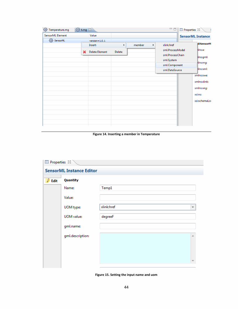
To create a process model a person should click on sensorML element inside
Temperature.rng and select from the drop down box the sml.Component member. Figure
14 shows the process of adding the sml.Component element. The inputs, identifier, and
the method of the process model should be added to this element. To add the inputs a
person has to add the inputList element and then add the input to the inputList. Figure 15
shows how to enter the values for an input. The identifier specifies the metadata part.
Figure 16 shows how to enter the values for an identifier, the Manufacturer. The method
element specifies the file path for the process method. Figure 17 shows how to enter the
process method‟s path.
To generate a system (process chain) a new sensorMLInstance should be created and
sml.System must be selected as the SensorML member. A ConnectionList must be added

42
as the System‟s element, and then connections must be added to the connection List. The
connections have a source and destination part. The source is the component from where
the attribute is coming and the destination is the component that is receiving the attribute.
The source and destination for a sensor system with a Temperature sensor is:
Source=Temperature/Temp1
Destination=Temperature/Temp1
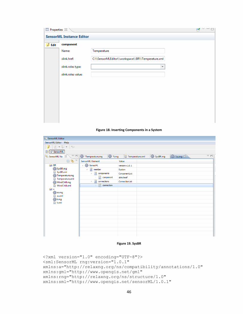
Figure 19 shows the screen shot of a process chain called SysBR.rng.
After having specified the requirements of SCT the Beans will be generated in a separate
project. It is enough to run this project and obtain the desired results.
Code 7 and Code 8 show the code for Temperature. xml and SysBR.xml respectively.

43
Figure 13. Creating a new SensorML instance
44
Figure 14. Inserting a member in Temperature
Figure 15. Setting the input name and uom

45
Figure 16. Inserting a new Identifier
Figure 17. Temperature.rng
46
Figure 18. Inserting Components in a System
Figure 19. SysBR
<?xml version="1.0" encoding="UTF-8"?>
<sml:SensorML rng:version="1.0.1"
xmlns:a="http://relaxng.org/ns/compatibility/annotations/1.0"
xmlns:gml="http://www.opengis.net/gml"
xmlns:rng="http://relaxng.org/ns/structure/1.0"
xmlns:sml="http://www.opengis.net/sensorML/1.0.1"

47
xmlns:swe="http://www.opengis.net/swe/1.0.1"
xmlns:xlink="http://www.w3.org/1999/xlink"
xmlns:xng="http://xng.org/1.0">
<sml:member>
<sml:Component>
<sml:identification>
<sml:IdentifierList>
<sml:identifier name="Manufacturer">
<sml:Term
definition="urn:ogc:def:identifier:manufacturer">
<sml:value>Crossbow</sml:value>
</sml:Term>
</sml:identifier>
<sml:identifier name="Mote Type">
<sml:Term
definition="urn:ogc:def:identifier:moteType">
<sml:value>Mica2</sml:value>
</sml:Term>
</sml:identifier>
<sml:identifier name="Sensor Board">
<sml:Term
definition="urn:ogc:def:identifier:sensorBoard">
<sml:value>MTS310</sml:value>
</sml:Term>
</sml:identifier>
</sml:IdentifierList>
</sml:identification>
<sml:inputs>
<sml:InputList>
<sml:input name="Temp1">
<swe:Quantity>
<swe:uom code="" xlink:href="degreeF"/>
</swe:Quantity>
</sml:input>
</sml:InputList>
</sml:inputs>
<sml:method xlink:href="C:\\methods\\Calibration.java"/>
</sml:Component>
</sml:member>
</sml:SensorML>
Code 7. Temperature.xml
<?xml version="1.0" encoding="UTF-8"?>
<sml:SensorML rng:version="1.0.1"
xmlns:a="http://relaxng.org/ns/compatibility/annotations/1.0"
xmlns:gml="http://www.opengis.net/gml"
xmlns:rng="http://relaxng.org/ns/structure/1.0"
xmlns:sml="http://www.opengis.net/sensorML/1.0.1"

48
xmlns:swe="http://www.opengis.net/swe/1.0.1"
xmlns:xlink="http://www.w3.org/1999/xlink"
xmlns:xng="http://xng.org/1.0">
<sml:member>
<sml:System>
<sml:classification>
<sml:ClassifierList>
<sml:classifier name="sensorType">
<sml:Term
definition="urn:ogc:def:identifier:sensorType">
<sml:value>Temperature</sml:value>
</sml:Term>
</sml:classifier>
</sml:ClassifierList>
</sml:classification>
<sml:position xlink:href="">
<swe:Position>
<swe:state>
<swe:Vector/>
<swe:SquareMatrix>
<swe:elementCount/>
<swe:elementType name=""/>
</swe:SquareMatrix>
</swe:state>
</swe:Position>
</sml:position>
<sml:components>
<sml:ComponentList>
<sml:component name="Temperature"
xlink:href="C:\\SensorMLEditor\\workspace\\BR\\Temperature.xml"/>
<sml:component name="WindChill"
xlink:href="C:\\SensorMLEditor\\workspace\\BR\\WindChill.xml"/>
</sml:ComponentList>
</sml:components>
<sml:positions>
<sml:PositionList/>
</sml:positions>
<sml:connections>
<sml:ConnectionList>
<sml:connection>
<sml:Link>
<sml:source ref="Temperature/Temp1"/>
<sml:destination ref="Temperature/Temp1"/>
</sml:Link>
</sml:connection>
<sml:connection>
<sml:Link>
<sml:source ref="WindChill/Windspeed"/>
<sml:destination ref="WindChill/Windspeed"/>
</sml:Link>
</sml:connection>
<sml:connection>
49
<sml:Link>
<sml:source ref="Temperature/Temp1"/>
<sml:destination ref="WindChill/Temp1"/>
</sml:Link>
</sml:connection>
</sml:ConnectionList>
</sml:connections>
</sml:System>
</sml:member>
</sml:SensorML>
Code 8. SysBR.xml
3.3.2. Adding a new sensor (WindChill ) to the system
In order to add a new sensor to the system two things must be done:
A new process model must be created
The process chain (system) must change
Suppose a new sensor called WindChill wants to be added to the system. In this case the
process model for WindChill must be created in the same way the process model for
Temperature was created. The only difference is that WindChill has two inputs instead of
one input.
The process chain should be changed to reflect the new connections in the sensor system.
If, for example, the old temperature sensor in the system is connected to the temperature
sensor in WindChill this new connection should be depicted as follows:
Source=Temperature/Temp1
Destination=WindChill/Temp1
Where the first element is the component‟s name and the second element is the attributes
name.

50
Figure 20. WindChill Component
Code 9 shows the code for WindChill.xml, whereas code 10 is the parts of SysBR.xml
that have changed.
<?xml version="1.0" encoding="UTF-8"?>
<sml:SensorML rng:version="1.0.1"
xmlns:a="http://relaxng.org/ns/compatibility/annotations/1.0"
xmlns:gml="http://www.opengis.net/gml"
xmlns:rng="http://relaxng.org/ns/structure/1.0"
xmlns:sml="http://www.opengis.net/sensorML/1.0.1"
xmlns:swe="http://www.opengis.net/swe/1.0.1"
xmlns:xlink="http://www.w3.org/1999/xlink"
xmlns:xng="http://xng.org/1.0">
<sml:member>
<sml:Component>
<sml:inputs>
<sml:InputList>
<sml:input name="Windspeed">
<swe:Quantity>
<swe:uom code="" xlink:href="perMeter"/>
</swe:Quantity>
</sml:input>

51
<sml:input name="Temp1">
<swe:Quantity>
<swe:uom code="" xlink:href="degreeF"/>
</swe:Quantity>
</sml:input>
</sml:InputList>
</sml:inputs>
<sml:method xlink:href="C:\\methods\\WindChill.java"/>
</sml:Component>
</sml:member>
</sml:SensorML>
Code 9. WindChill .xml
<sml:connections>
<sml:ConnectionList>
<sml:connection>
<sml:Link>
<sml:source ref=”Temperature\Temp1” />
<sml:destination ref=”Temperature\Temp1” />
</sml:Link>
</sml:connection>
<sml:connection>
<sml:Link>
<sml:source ref=”WindChill\Windspeed” />
<sml:destination ref=”WindChill\Windspeed” />
</sml:Link>
</sml:connection>
<sml:connection>
<sml:Link>
<sml:source ref=”Temperature\Temp1” />
<sml:destination ref=”WindChill\Temperature” />
</sml:Link>
</sml:connection>
</sml:ConnectionList>
</sml:connections>
Code 10. Changed parts of SysBR.xml
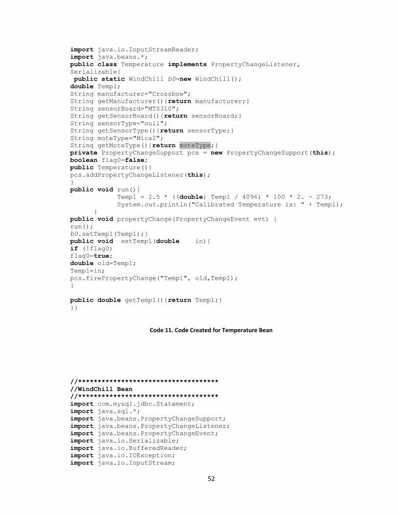
Code 11 shows the Java Beans Code Created for Temperature. Code 12 shows the Java
Beans Code created for WindChill.
//************************************
//Temperature Bean
//************************************
import com.mysql.jdbc.Statement;
import java.sql.*;
import java.beans.PropertyChangeSupport;
import java.beans.PropertyChangeListener;
import java.beans.PropertyChangeEvent;
import java.io.Serializable;
import java.io.BufferedReader;
import java.io.IOException;
import java.io.InputStream;
52
import java.io.InputStreamReader;
import java.beans.*;
public class Temperature implements PropertyChangeListener,
Serializable{
public static WindChill b0=new WindChill();
double Temp1;
String manufacturer="Crossbow";
String getManufacturer(){return manufacturer;}
String sensorBoard="MTS310";
String getSensorBoard(){return sensorBoard;}
String sensorType="null";
String getSensorType(){return sensorType;}
String moteType="Mica2";
String getMoteType(){return moteType;}
private PropertyChangeSupport pcs = new PropertyChangeSupport(this);
boolean flag0=false;
public Temperature(){
pcs.addPropertyChangeListener(this);
}
public void run(){
Temp1 = 2.5 * ((double) Temp1 / 4096) * 100 * 2. - 273;
System.out.println("Calibrated Temperature is: " + Temp1);
}
public void propertyChange(PropertyChangeEvent evt) {
run();
b0.setTemp1(Temp1);}
public void setTemp1(double in){
if (!flag0)
flag0=true;
double old=Temp1;
Temp1=in;
pcs.firePropertyChange("Temp1", old,Temp1);
}
public double getTemp1(){return Temp1;}
}}
Code 11. Code Created for Temperature Bean
//************************************
//WindChill Bean
//************************************
import com.mysql.jdbc.Statement;
import java.sql.*;
import java.beans.PropertyChangeSupport;
import java.beans.PropertyChangeListener;
import java.beans.PropertyChangeEvent;
import java.io.Serializable;
import java.io.BufferedReader;
import java.io.IOException;
import java.io.InputStream;

53
import java.io.InputStreamReader;
import java.beans.*;
public class WindChill implements PropertyChangeListener, Serializable{
double Windspeed;
double Temp1;
String manufacturer=”null”;
String getManufacturer(){return manufacturer;}
String sensorBoard=”null”;
String getSensorBoard(){return sensorBoard;}
String sensorType=”null”;
String getSensorType(){return sensorType;}
String moteType=”null”;
String getMoteType(){return moteType;}
private PropertyChangeSupport pcs = new PropertyChangeSupport(this);
53oolean flag0=false;
53oolean flag1=false;
public WindChill(){
pcs.addPropertyChangeListener(this);
}
public void run(){
double out = 35.74 + 0.6215 * Temp1 – 35.75* Math.pow(Windspeed,
0.16) + 0.4275 * Temp1* Math.pow(Windspeed, 0.16);
System.out.println(“Wind Chill is: “ + out);
}
public void propertyChange(PropertyChangeEvent evt) {
run();
}
public void setWindspeed(double in){
if (!flag0)
flag0=true;
double old=Windspeed;
Windspeed=in;
pcs.firePropertyChange(“Windspeed”, old,Windspeed);
}
public void setTemp1(double in){
if (!flag1)
flag1=true;
double old=Temp1;
Temp1=in;
pcs.firePropertyChange(“Temp1”, old,Temp1);
}
public double getWindspeed(){return Windspeed;}
public double getTemp1(){return Temp1;}
}
Code 12. Code created for WindChill Bean

54
3.4. Using the Components created by SCT One of the best examples of the usage of components creates by SCT is to use the
components generated by SCT to create outputs that will be stored in a Data Base and
later on use these data as the sensor history to draw graphs, etc.
Figure 21 and 22 show the tables for the WindChill and Temperature sensors
respectively. Code 13 and 14 shows the SQL code for creating tables for these
components. The primary key helps differentiate each table entry from each other. The
foreign key helps preserve the database consistency. Here, Temp1 in WindChill is
dependent on Temp1 in Temperature; if Temp1 in Temperature gets deleted this will
affect Temp1 in WindChill.
These tables are created by the SCT component‟s users. These users will use the outputs
(and maybe the inputs of the sensors in their table). A suggestion of the fields that should
be included in the tables are:
An auto-incrementing, unique primary key.
The output of the sensor
The inputs of the sensor (some of which might reference other tables. For example
the field Temp1 in the WindChill table will have to reference the field
Temperature in the table Temperature. )
id WindChill Temp1 Windspeed
Figure 21. WindChill Table
Id Temperature Temp1
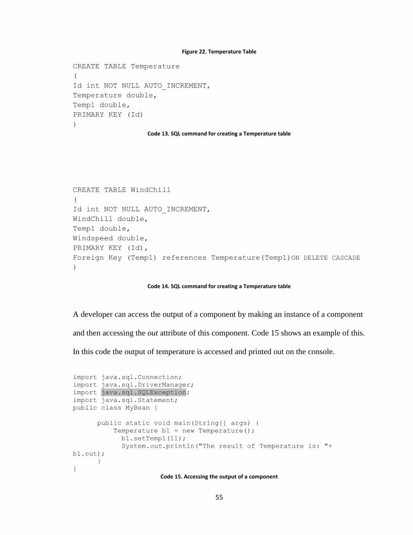
55
Figure 22. Temperature Table
CREATE TABLE Temperature
(
Id int NOT NULL AUTO_INCREMENT,
Temperature double,
Temp1 double,
PRIMARY KEY (Id)
)
Code 13. SQL command for creating a Temperature table
CREATE TABLE WindChill
(
Id int NOT NULL AUTO_INCREMENT,
WindChill double,
Temp1 double,
Windspeed double,
PRIMARY KEY (Id),
Foreign Key (Temp1) references Temperature(Temp1)ON DELETE CASCADE
)
Code 14. SQL command for creating a Temperature table
A developer can access the output of a component by making an instance of a component
and then accessing the out attribute of this component. Code 15 shows an example of this.
In this code the output of temperature is accessed and printed out on the console.
import java.sql.Connection;
import java.sql.DriverManager;
import java.sql.SQLException;
import java.sql.Statement;
public class MyBean {
public static void main(String[] args) {
Temperature b1 = new Temperature();
b1.setTemp1(11);
System.out.println("The result of Temperature is: "+
b1.out);
}
}
Code 15. Accessing the output of a component

56
Code 16 shows how to insert the output value to the database. This code inserts the
output value of the Temperature sensor into the Temperature table.
Figure 23 shows the contents of the Temperature table. The last row shows the result for
code 15.
import java.sql.*;
public class CreateMySqlTable {
public static void main(String[] args) {
System.out.println("Creating a Mysql Table to Store
Java Types!");
Connection con = null;
String url = "jdbc:mysql://localhost:3306/";
String db = "mydb";
String driver = "com.mysql.jdbc.Driver";
String user = "root";
String pass = "root";
try {
Class.forName(driver).newInstance();
con = DriverManager.getConnection(url + db, user,
pass);
try {
Statement st = con.createStatement();
Temperature b0 = new Temperature();
b0.setTemp1(11);
st.executeUpdate("INSERT INTO
Temperature(Temperature) VALUES ( "
+ b0.out + ")");
con.close();
} catch (SQLException s) {
System.out.println(s.getMessage());
}
} catch (Exception e) {
e.printStackTrace();
}
}
}
Code 16. Inserting a new value inside the database
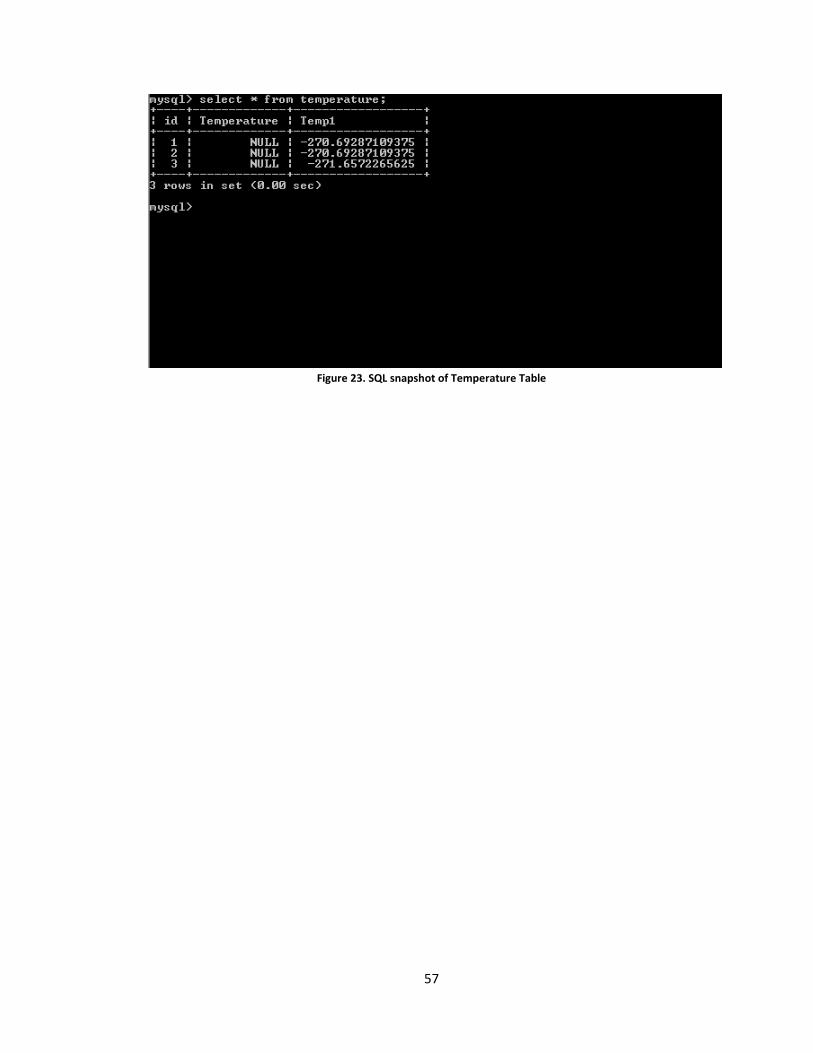
57
Figure 23. SQL snapshot of Temperature Table

58
Chapter 4 Testing and Validation
In this section an analysis of the SensorML / Component translator is performed by
comparing it to an existing Java-based middleware sensor system called SensIV that was
also developed at the same laboratory.
4.1. The SensIV system
The SensIV system is a sensor network that measures the temperature in a field using a
set of temperature sensors consisting of a set of wireless sensors forwarding their data to a
Java-based middleware platform.
Figure 24 shows the structure of the SensIV message. Each of the fields in this message
with the exception of the readings field (which has 4* 2 Bytes) has a Bytes size. The
important fields to add new sensors are: kiwi and mango hence only these two fields
would be explained. Kiwi specifies the settings i.e.: Normal, Discovery, etc. Mango
specifies the sensor boards for example MDA300. The combination of these two fields
gives us all our possibilities.
Figure 24.SensIV message structure
The SensIV middleware application is written in Java and is characteristic of a classical
OO program. The design of SensIV is based on the proper interpretation of the incoming
message from the sensor network, the type of sensor that sent the message. The details of
the encoding of this information in the SensIV message are not relevant to this thesis.
59
The SensIV application is composed of many classes. Here, only five classes which are
relevant to the work that is being carried out are included. These classes are: DemoMotes,
FruitSalad, Lizard, DataConvert, Constants, MTS300, MTS310, MDA300. DemoMotes
is the main executing class of SensIV; DemoMotes calls FruitSalad with the readings it
has received from the middleware and the specific kiwi (that specifies the sensor settings)
and the Mango (which specifies the sensor boards); FruitSalad calls Lizard using the
getindex method with kiwi and mango parameters. The Mango links Kiwis to their
corresponding data position arrays (arrays that provide the index locations for all the data
for any specified kiwi).
The core classes that represent the sensors in SensIV are based on the type of sensor
boards in the sensor network. In this case these are the Crossbow MTS300, MTS310, and
MDA300 sensor boards. These classes are in effect comparable to the process models in
SensorML except that in SensIV each sensor board type has only a single instance of the
sensor board class, while when SensorML is used each sensor has a SensorML file
describing it resulting in a Java bean for each sensor in the system.
Figure 25 shows the class diagram of SensIV.
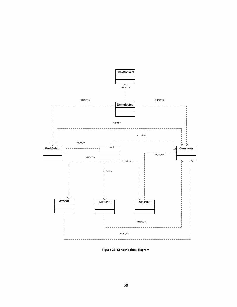
60
DemoMotes
FruitSalad Lizard
DataConvert
Constants
MTS300 MTS310 MDA300
«uses»
«uses»
«uses»
«uses»
«uses»
«uses»
«uses»
«uses»
«uses»
«uses»
«uses»
«uses»
Figure 25. SensIV's class diagram
61
The purpose of this analysis is to learn if there is an improvement over SensIV in using
the SensorML / Component translator in terms of:
1. User‟s effort in changing the sensor system.
2. Lines of code written.
3. Correctness of SensIV and the SCT.
4. Cohesion and Coupling of SensIV and of the SCT.
For the first metric a survey is handed out to the users and they are asked to fill it in.
For the second metric changes are made to the system and the result of the system
executions are presented. Two scenarios are considered. For each scenario the total lines
of code that have to be added by the user to change the sensor system are counted. For
SensIV the lines of code have to be typed in by the user in each of the classes that will be
changing, whereas for SCT the user implements the changes by using the
SensorMLEditor. The two scenarios are:
1. Scenario one: When there are multiple instances of a single sensor type (for
example multiple instances of a Temperature sensor.)
2. Scenario two: When there are multiple instances of multiple sensor types (for
example multiple instances of a Temperature and Humidity sensor.)
The third metric ―testing the correctness‖ means testing SensIV and the translator in
different scenarios and making sure they both work correctly (in an error free manner
producing the correct results) The third metric uses two different scenario: one scenario
with two instances of one kind of sensor for both systems and one scenario with two
different kind of sensors for both systems.
The fourth metric cohesion is measured with an eclipse plug-in called Metrics 1.3.6 [22].

62
4.2. User’s effort in changing the sensor system
For this analysis several graduate and undergraduate students, and professors with
software engineering background were asked to modify SensIV code as well as to use the
SensorML / Component translator.
A two hour session was held and instructions were handed to these software developers.
The software developers had different initial levels of knowledge about SensIV and the
SensorML / Component translator but all of them were developers with a fundamental
knowledge of Java and of XML. Before the software developers performed the code
change exercise their development environment was set up with the appropriate files.
Code development was performed on the Eclipse IDE.
The software developers where then guided in how to add a new sensor using both the
SensorML / Component translator and then the SensIV system. After they all succeeded
doing this they proceeded to fill in a survey about their experience of using both systems.
The following questions were asked about each approach.
1. Time spent learning how to work with system
2. Correctness of code (did errors occur and did the system work as you were
expecting it to work).
3. Ease of use (on a scale from 1–5).
4. Wealth of information captured by the system on the sensor (on a scale from 1–5).
5. Additional comments.
Also the developers were categorized as follows:

63
Software developers who had knowledge of SensIV but no knowledge of the
SensorML / Component translator.
Software developers who were not acquainted with any of the 2 sensor systems
and they were using both for the first time.
Software developers with knowledge of both SensIV and the SensorML /
Component translator.
The results of the survey are captured in the following sub-sections.
4.2.1. Results for software engineers who had knowledge of SensIV
but no knowledge of the SCT
There were 2 developers who fell into this category. The first developer thought that
learning SensIV was very time consuming, this user mentioned there were some errors
when changes were implemented, from the point of view of ease of use this user
mentioned that SensIV was quite difficult to get acquainted with, for wealth of
information this user misunderstood the question so the user‟s answer is omitted in this
section. About SCT this developer was of the idea that the only thing that confused him
from a learning point of view was setting the paths, this user mentioned that the code of
SCT was correct, from the point of view of ease of use this user pointed out that from a
configuration point‟s of view SCT was still not completely easy to use for non experts,
here again the user misunderstood the question about wealth of information and thus the
answer is omitted from this section.
The second developer in this category commented that it took him an hour to learn to
work with SensIV, he wrote a few lines of code which he said were necessary for
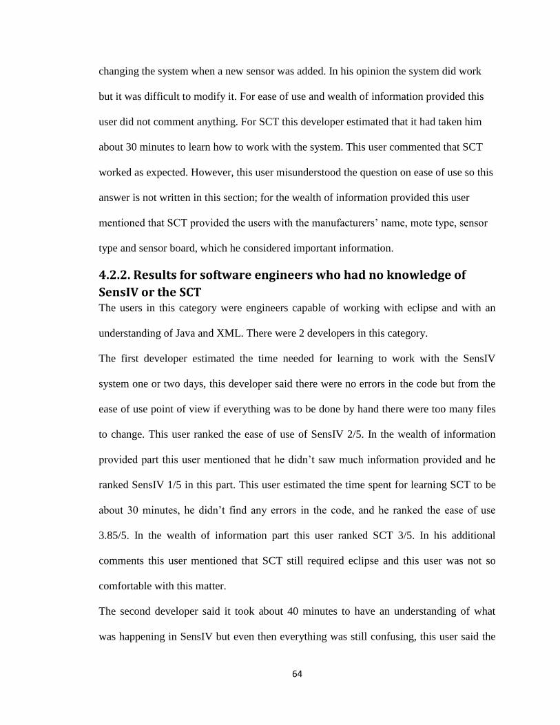
64
changing the system when a new sensor was added. In his opinion the system did work
but it was difficult to modify it. For ease of use and wealth of information provided this
user did not comment anything. For SCT this developer estimated that it had taken him
about 30 minutes to learn how to work with the system. This user commented that SCT
worked as expected. However, this user misunderstood the question on ease of use so this
answer is not written in this section; for the wealth of information provided this user
mentioned that SCT provided the users with the manufacturers‟ name, mote type, sensor
type and sensor board, which he considered important information.
4.2.2. Results for software engineers who had no knowledge of
SensIV or the SCT The users in this category were engineers capable of working with eclipse and with an
understanding of Java and XML. There were 2 developers in this category.
The first developer estimated the time needed for learning to work with the SensIV
system one or two days, this developer said there were no errors in the code but from the
ease of use point of view if everything was to be done by hand there were too many files
to change. This user ranked the ease of use of SensIV 2/5. In the wealth of information
provided part this user mentioned that he didn‟t saw much information provided and he
ranked SensIV 1/5 in this part. This user estimated the time spent for learning SCT to be
about 30 minutes, he didn‟t find any errors in the code, and he ranked the ease of use
3.85/5. In the wealth of information part this user ranked SCT 3/5. In his additional
comments this user mentioned that SCT still required eclipse and this user was not so
comfortable with this matter.
The second developer said it took about 40 minutes to have an understanding of what
was happening in SensIV but even then everything was still confusing, this user said the
65
code executed correctly, from the point of view of ease of use this user ranked SensIV
3/5, from the point of view of wealth of information provided he ranked SensIV 4/5 but
he mentioned information that was not provided by SensIV so this answer can be
disqualified, for SCT this user commented that it took 45 minutes to learn to use the
system, the only thing this user was concerned in from the stand point of correctness was
the fact that when a person minimized the SensorMLEditor it closed down automatically
or key combinations like CTRL+A didn‟t work in the editor. The second developer was
impressed with the ease of use of the SensorML / Component translator, to quote “I am
impressed with the amount of effort put in and it seems to be a really good system making
the developers life easy”. This developer gave 4/5 for ease of use of the SensorML /
Component translator and 5/5 for the amount of information the system
4.2.3. Results for software engineers who had knowledge of both
SensIV and the SCT. There was only one developer that filled in the survey from this category. This developer
was acquainted with both SensorML and SensIV systems as he had worked closely with
both systems from the beginning.
This developer said it had taken them an hour to learn to work with SensIV, they said the
code had been correct, they ranked the ease of use of SensIV 3/5 and the wealth of
information provided by SensIV 1/5. About SCT this user estimated the learning time to
be about an hour, and the code to be correct. They ranked SCT 4/5 for ease of use and
3.5/5 for wealth of information provided. This developer commented that understanding
SensorML was easier than SensIV but here again there were configuration errors.
Table 3 shows a summary of the survey taken by the software developers.
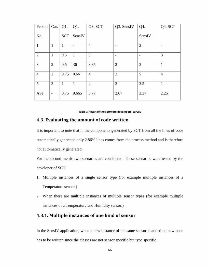
66
Person
No.
Cat. Q1.
SCT
Q1.
SensIV
Q3. SCT Q3. SensIV Q4.
SensIV
Q4. SCT
1 1 1 - 4 - 2 -
2 1 0.5 1 3 - - 3
3 2 0.5 36 3.85 2 3 1
4 2 0.75 0.66 4 3 5 4
5 3 1 1 4 3 3.5 1
Ave - 0.75 9.665 3.77 2.67 3.37 2.25
Table 3.Result of the software developers' survey
4.3. Evaluating the amount of code written.
It is important to note that in the components generated by SCT from all the lines of code
automatically generated only 2.86% lines comes from the process method and is therefore
not automatically generated.
For the second metric two scenarios are considered. These scenarios were tested by the
developer of SCT:
1. Multiple instances of a single sensor type (for example multiple instances of a
Temperature sensor.)
2. When there are multiple instances of multiple sensor types (for example multiple
instances of a Temperature and Humidity sensor.)
4.3.1. Multiple instances of one kind of sensor
In the SensIV application, when a new instance of the same sensor is added no new code
has to be written since the classes are not sensor specific but type specific.

67
In the case of the SensorML / Component translator 10 new lines have to be added. These
lines are added using an editor. So in this case the ratio of the lines of code written in
SensIV to the lines of code written in SCT is equal to 0 so in this case SensIV is better.
4.3.2. Multiple instances and multiple types of sensors
In the SensIV system we need to add totally 32 lines of code to capture the new sensor
type. In the SensorML / Component translator the amount of new coding would be 14. So
in this case the ratio of the lines of code written in SensIV to the lines of code written in
SCT is equal to 2 so in this case SensIV is better.
4.4. Measuring the correctness
In this part the components were tested using simulated data and gave the same result as
SensIV.
4.5.Cohesion and Coupling
4.5.1. Cohesion
Cohesion is defined as how strongly related to each other the functionalities of software
modules are. Coupling is defined as the knowledge each class has of other classes.
In this thesis the Cohesion in Methods test of the Eclipse Metrics 1.3.6 plugin was used to
measure the coupling in both the SensIV code and the code generated by the SensorML /
Component Translator.
The lack of cohesiveness in this plug-in is measured using an algorithm called
Henderson-Sellers. The formula used in this method is:
M(A)-M/1-M

68
Where M(A) is the average number of methods that access all attributes, M is the total
number of methods, and A is the number of attributes.
This formula shows that the more the methods access the attributes in a class the higher
the cohesiveness. The measure of cohesion is not well applicable to Java Beans because
access of classes is limited to getter and setter methods and there is a getter and setter
value for each attribute. This formula will lead to a value which is very close to one. For
example for a Java Bean where:
A=5, M(A)=2, M=10
The lack of cohesiveness in this case is equal to 8/9. In the case of SensIV code the
cohesion factor is about 0.785. In the case of the code generated by the SensorML /
Component Translator the cohesion factor is about 0.332.
Additions of new sensor types to both systems had little impact on the cohesiveness of the
code. In both cases the values for lack of cohesion remained nearly the same.
4.5.2. Coupling To compare the coupling of the components generated by SCT to SensIV a measure
called Method Invocation Coupling (MIC) is used. MIC is defined as the number of
classes that are coupled to a certain class [23]. The formula for MIC is:
MIC=nMIC/(N-1)
Where nMIC= number of classes that use a particular class
N=total number of classes
As an example when there are two components generated by SCT. (For example
WindChill and Temperature components).
MIC (Temperature)=1/3=33%
MIC(WindChill)=1/3=33%
MIC(connectorBean)=1/3=33%
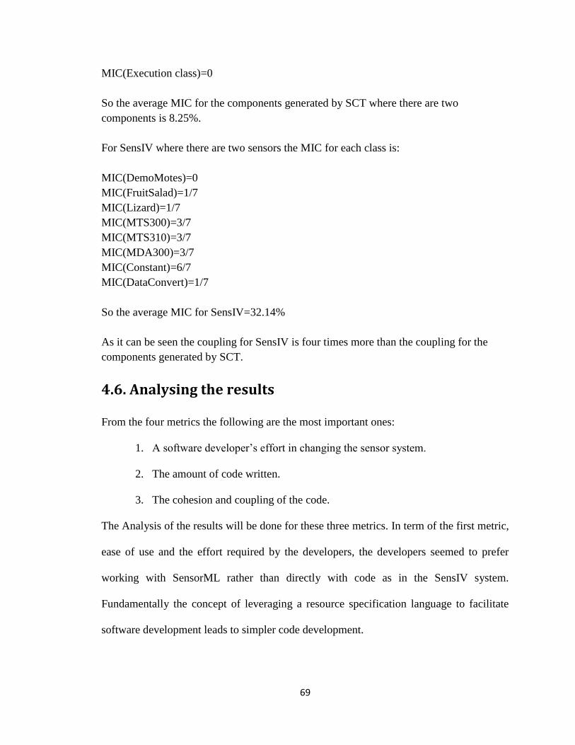
69
MIC(Execution class)=0
So the average MIC for the components generated by SCT where there are two
components is 8.25%.
For SensIV where there are two sensors the MIC for each class is:
MIC(DemoMotes)=0
MIC(FruitSalad)=1/7
MIC(Lizard)=1/7
MIC(MTS300)=3/7
MIC(MTS310)=3/7
MIC(MDA300)=3/7
MIC(Constant)=6/7
MIC(DataConvert)=1/7
So the average MIC for SensIV=32.14%
As it can be seen the coupling for SensIV is four times more than the coupling for the
components generated by SCT.
4.6. Analysing the results
From the four metrics the following are the most important ones:
1. A software developer‟s effort in changing the sensor system.
2. The amount of code written.
3. The cohesion and coupling of the code.
The Analysis of the results will be done for these three metrics. In term of the first metric,
ease of use and the effort required by the developers, the developers seemed to prefer
working with SensorML rather than directly with code as in the SensIV system.
Fundamentally the concept of leveraging a resource specification language to facilitate
software development leads to simpler code development.
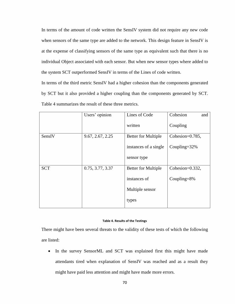
70
In terms of the amount of code written the SensIV system did not require any new code
when sensors of the same type are added to the network. This design feature in SensIV is
at the expense of classifying sensors of the same type as equivalent such that there is no
individual Object associated with each sensor. But when new sensor types where added to
the system SCT outperformed SensIV in terms of the Lines of code written.
In terms of the third metric SensIV had a higher cohesion than the components generated
by SCT but it also provided a higher coupling than the components generated by SCT.
Table 4 summarizes the result of these three metrics.
Users‟ opinion Lines of Code
written
Cohesion and
Coupling
SensIV 9.67, 2.67, 2.25 Better for Multiple
instances of a single
sensor type
Cohesion=0.785,
Coupling=32%
SCT 0.75, 3.77, 3.37 Better for Multiple
instances of
Multiple sensor
types
Cohesion=0.332,
Coupling=8%
Table 4. Results of the Testings
There might have been several threats to the validity of these tests of which the following
are listed:
In the survey SensorML and SCT was explained first this might have made
attendants tired when explanation of SensIV was reached and as a result they
might have paid less attention and might have made more errors.
71
Nearly all the attendants were using SCT from scratch while 3/5 attendants were
already familiar with SensIV this might have had the negative affect that changing
an already existing sensor system might have been harder than becoming familiar
with another sensor system from scratch.
72
Chapter 5 Comparison In this Chapter SCT is compared with the approaches presented in section 2.2. The goal is
to understand the similarities and differences between SCT and these approaches.
5.1. Insense
In this section the similarities and discrepancies between Insense [14][15] and the
SensorML / Component translator (SCT), are examined.
There are several resemblances between Insense and SCT these include:
Both Systems generate components.
Both systems have input and output channels, which have to be compatible with
the input or output channel of the component they are connecting to.
Both systems create code for execution. SCT creates Java Beans from SensorML,
whereas Insense creates C code from Java.
Both systems provide mutual exculsion in the codes they create. SCT does this by
using events: each component registers for events and waits for event notifications
while Insense uses a semaphore for this purpose. In general both systems provide
means by which components can communicate with each other.
Even though there are a lot of similarities between both systems a few differences also
exist between them:
Insense has an interface part and this is the means by which components
communicate with each other, whereas SCT uses getter and setter methods for
component communication.

73
Another difference between Insense and SCT is that in the code generated by
Insense there is a part called the behavior part, which runs until some component
tells it to stop. The components generated by the SCT are controlled by events,
they start when an event occurs and end when the code for servicing the event
ends.
In Insense there are four operations on the input and output channels of a
component: send, receive, disconnect and connect; SCT doesn‟t directly support
this.
5.2. UM-RTCOM There are some differences between UM-RTCOM [16][17][18] and SCT. These are:
There are two kinds of components in UM-RTCOM: active and passive. Active
components are the ones specifying the execution flow while the passive ones are
used for mutual exclusion on shared resources.
The components generated by SCT do both jobs of active and passive components
in one. Mutual exclusion is ensured by using event handling and the executing
component is always the component triggered by the event.
There are two main types of components in UM-RTCOM: primitive and generic.
Generic components are composed of other components. Whereas in SCT each
process model is mapped to one and only one component so in this work there are
just primitive components. UM-RTCOM is a framework for real time systems and
as such it is not targeted to sensor systems but could be used to develop sensor
specific components.
SensorML could be mapped into UM-RTCOM but with some difficulty since it is
a generic component design tool that supports real-time analysis.

74
Another difference is that the component in UM-RTCOM consists of an interface
part which specifies the provided and required interfaces. These interfaces are the
means by which components communicate, whereas components created by SCT
communicate via getter and setter methods.
The abstract model in UM-RTCOM let us perform real time analysis such as
deadlock freedom while the abstract model in this thesis (SensorML) lets us
specify the connections and the inputs and outputs to the components.
In UM-RTCOM the only way components can communicate is by explicitly using
synchronization primitives (wait, raise, call) in SCT this is done implicitly by
using events.
There are several similarities between UM-RTCOM and SCT. These include:
Both the components in UM-RTCOM and the components generated by SCT
have an implementation part, which is the execution part of the components.
Both systems have parts that use events.
5.3. UML Platform Independent Component Model to Platform Specific Component Models The similarities between this approach [19] and SCT are:
The approach presented maps UML to component based languages like Enterprise
Java Beans (EJB) or Corba Component Model (CCM). The work done in this
thesis converts SensorML to Java Beans. As it can be seen both approaches are
very similar: both approaches convert a modeling language to a component based
language.
75
Both approaches create components and have some method by which components
can communicate. In this approach components can communicate by using Ports,
which are interfaces, while in the components generated by SCT components
communicate by using setter and getter methods.
In this approach in order to connect components to each other connectors are
used. The connectors that are comparable to the connections between the
components created by SCT are called assembly connectors. The assembly
connector exists between the ports (required and provided.)
The differences between the two systems are:
One of the main differences between the two systems is that UML is a general
modeling language while SensorML is a modeling language specific to sensors.
Another difference between the two systems is that in this approach one of the
composing parts of a component is parts, which are subcomponents. In the
components generated by SCT there is nothing comparable to parts.
One of the types of connectors that does not exist in the components in this thesis
is the delegation connector. The delegation connector is used to connect
components and sub components together.
To map the UML model to EJB each component is mapped to a bean (for each
bean there exists an interface part and an implementation part) this is very similar
to the work carried out in this thesis were every process model is mapped into a
component or a Bean but with the difference that in this thesis the SensorML
model gets mapped into Beans that only have the implementation part.
76
5.4. V3studio
The discrepancies between V3studio [20] and SCT are:
V3studio provides a more graphical form of representation than SensorML and
SCT. V3studio defines three models: one for the component view, one for the
state machine and one for the activity diagram. These models are implemented
used the graphical model framework (GMF).
In V3studio there exists a component type called the complex components that
does not exist in the components generated by SCT.
In V3studio component communication is done via interfaces while in the
components generated by SCT this is done via getter and setter methods.
In V3studio communication parts are called ports. A communication part that
doesn‟t exist in the components created by SCT, and which is used to connect
complex components together, is called the assembly port.
In the behavioral model of V3studio there are vertexes that have no equivalent in
the components created by SCT and are called pseudo states, which are not real
states but they can mark the initial or final states of the state diagram.
The second part of behavioral diagrams is transitions. One kind of transition that
has no equivalent in this work are internal transitions, which are a loop in the
same state.
The similarities between V3studio and the work done in this thesis are:
V3studio resembles SensorML in the sense that in comparison to UML it is a
more constrained language. V3studio can be considered as a meta-model that
describes a subset of UML and as such it is UML compliant and vice versa.

77
The state diagram in V3studio is comparable to a process chain that describes
what components are connected to each other hence specifying the different states
a component will be in when it would be translated.
The activity diagram in V3studio specifies the flow of data and is comparable to
the components generated by SCT.
The component type that exists in both V3studio and the components generated by
SCT are simple components.
Both approaches provide means by which components can communicate. The
ports which are comparable to the communication part in the components
generated by SCT are called Delegation portlinks.
Another similarity between the two systems is that in both systems the means by
which components communicate has to have compatible types.
In the behavioral model of V3stdudio there are two components: vertexes and
transitions. The vertexes that are equivalent to the different stages of a component
life are called states.
External transitions are a kind of transitions that do have an equivalent in this
work. External transitions are comparable to events, which change the state in
which a component is in.

78
5.5. COM and Eiffel Some of the differences between the two methods include:
A difference between Java Beans and COM [13] is that in Java Beans there is no
actual use of pointers; Java Beans uses Components, which are called Beans, and
the connections between these components is depicted with events.
Another difference between the components in COM and the components
generated by SCT is that all components in COM inherit from a component called
IUnknown. The components in this thesis don‟t inherit from anything hence they
are simple components.
IUnknown has a method called QueryInterface. QueryInterface is used to access
another interface and it can be compared to getter and setter methods.
COM has its own Interface Definition Language (IDL) and with that IDL it
defines the interface by which the components will interact.
Another difference is that COM can also work with distributed systems. In order
to work with distributed systems COM uses Remote Process Call (RPC). In the
work done in this thesis RPCs are not taken into consideration.
Some of the resemblances between the two approaches are:
In COM there exists a virtual pointer (vpointer) and the vpointer points to a virtual
table where the methods are and each entry in the virtual table points to a method
implementation. This is very similar to the referencing used in SensorML. In
SensorML each process chain references to a process model and the process
model references the process method. The process chain in SensorML can be

79
compared to the vpointer, the process model to the virtual table and the method
implementation to the process method.
Another similarity between the work done in this thesis and [12] is that in both
approaches the component model (the component model in [12] is COM and the
component model in this thesis is Java Beans) are not being used alone. Java
Beans is being used with a translator and COM is being used with an Object
Oriented (OO) language called Eiffel.
Both COM and the work done in this thesis have an implementation part. In the
case of COM this implementation part are the classes that implement the
interfaces; in the case of the work done in this thesis these are the Java Beans
generated by SCT.
COM lets component execute in both multi thread and not thread aware systems
that is why COM introduces a new concept called apartments. Each apartment
belongs to a single process but each process can have multiple apartments. Each
apartment can be either single or multi threaded. In the work done in this thesis
threads are not directly dealt with but if you consider that when a component is
waiting for events to happen other components can be executed this could be
comparable to what threads do.
In COM Type libraries, which are used to discover the type of interfaces, are
comparable to introspection in Java Beans.
5.6. JCM
The similarities between JCM [21] and the work done in this thesis are:
80
Both the component models in JCM and this thesis consist of connector models.
In this thesis the connections between the components is depicted with events.
Both models provide an implementation part for the components.
Both designs provide loosely coupling of Java classes. In JCM the components
interact via interfaces, whereas in this thesis the components interact via getter
and setter methods.
Some of the disparities between the two systems include:
The component model in JCM consists one part that the component model in this
thesis lacks; this part is called the specification model which provides interfaces
via which the components connect to each other. In the component model in this
thesis this is done with getter and setter methods.
Regardless of whether Java RMI is used or another form of RMI is chosen the
components created by SCT use Java Beans, which is a more constrained form of
Java.

81
Chapter 6 Conclusion and Future Work
6.1. Summary and Conclusion In this thesis a translator was designed and implemented to convert sensor languages to
component based frameworks. This was done with the purpose of enhancing the existing
design and implementation of sensor systems.
A variety of sensor languages were introduced. The two most common ones being:
SensorML and IEEE1451. SensorML was selected as the sensor language in this work
because it specified the execution process of a sensor system and this was very important
in determining the flow in component based design.
It was decided that Java Beans would be the most suitable component based framework in
this work because of its popularity between programmers and because of it being
platform independent.
The translator‟s design involved reading the process chain, process models and process
methods information from the SensorML document using a DOM parser and then create a
component (a Bean- components in Java Beans are Beans), then create the connections
between the Beans and then execute the Beans.
In the last chapter the SCT was compared against an existing sensor system (SensIV) to
learn if the objectives of the work (the enhancement of sensor systems in terms of ease of
use when changes occurred to sensor system) were fulfilled. The results showed that
when changes were introduced in the system the SCT was easier to work with than
SensIV: the SCT required less learning and it was easier to edit as all a user had to do was
to change SensorML documents in the SensorMLEditor whereas SensIV, even for the

82
people who had worked with it, was harder to work with and a change in SensIV could
mean adding new bugs to the system and editing SensIV is harder as the users have to go
to the source code and put their modifications there.
6.2. Future works In this work the SensorML to Java Beans mapping was done. We propose a new design
for future works: A SensorML to UML mapping.
The benefits of mapping SensorML to UML are the following:
1. UML is a general modeling language and it is not language dependent and as such
it can be mapped to many programming languages.
2. Other meta-models might exist for this purpose but UML is the best known meta-
model hence there are many tools supporting UML.
The way the translation between SensorML and UML can be done is via XMI. XMI (The
XML Metadata Interchange) is a standard for interchanging metadata via XML. XMI is
mostly considered as an interchange format for UML. It is enough to create a translator
that changes SensorML into an XMI format then importing the XMI file into a UML
editor; the translation could be done by the UML Editor to any supported programming
language.
Another modification that might be constructive is to modify the SensorML language. At
the moment SensorML allows the construction of one (sensor) System (or process chain).
Sensor networks consist of several correlated sensor systems. An amendment to the
SensorML architecture is suggested where more than one process chains can be added
and connected to each other.

83
References
[1] E.Y., Song. and K. Lee,” Understanding IEEE 1451— Understanding IEEE 1451-
Networked smart transducer interface standard - What is a smart transducer?,” IEEE
Instrumentation & Measurement Magazine, p. 11-17, April 2008.
[2] K. Lee. “IEEE 1451: A Standard in Support of Smart Transducer Networking,”
IEEE Instruments and Measurements Technology Conference, vol.2, p.525-528, May
2000.
[3] M. Botts, A. Robbins, “OpenGIS
Sensor Model Language (SensorML)
Implementation Specification”, SensorML Specification, 2007.
[4] M. Bott, G. Percivall, C. Reed and J. Davidson. “OGC White Paper – OGC
Sensor Web Enablement: Overview and High Level Architecture,” 2006. [Accessed
Sept 2009].
[5] A. Robin and Michael E. Botts.“ Creation of Specific SensorML Process Models”.
White Paper Earth System Science Center (NSSTC), 2006. [Accessed Jan 2010].
[6] C. Chen and S. Helal ,”Sifting Through the Jungle of Sensor Standards,” Pervasive
Computing, vol 7, no 4, p. 84‐88, Oct 2008.
[7] ECHONET Consortium, “ECHONET specification”, ECHONET Consortium, 2001,
Avaliable: http://www.echonet.gr.jp/english/8_kikaku/index.htm. [Accesssed Sept
2009].
[8] R. Englander." Developing Java Beans". Sebastopol, CA, USA: O'Reilly &
Associates, Inc, 1997.
[9] S. Havens, “OpenGIS Transducer Markup Language (TML) Implementation
Specification,”Open Geo Spatial Consortium, 2007, Available:
http://www.opengeospatial.org/standards/tml. [Accessed Sept 2009].
[10] S. Cox, “ Observations and Measurements,” Open Geo Spatial Consortium, 2006,
Avaliable: http://www.opengeospatial.org/standards/om, [Accessed Sept 2009].
84
[11] X. Cai, M.R. Lyu, K.F Wong , R. Ko,“Component-based software engineering:
technologies, development frameworks, and quality assurance schemes,p. 372 – 379,
Dec 2000.
[12] C. Szyperski, Component Software - Beyond Object Oriented Programming,
Addison-Wesley, Reading: M.A.,1997.
[13] R. Simon,"Building component software with COM and Eiffel,"Technology of
Object-Oriented Languages, 1998. TOOLS 26, p.364-374, Aug 1998.
[14] A. Dearle, D. Balasubramaniam, J. Lewis, R. Morrison,” A Component-Based
Model and Language for Wireless Sensor Network Applications,” Computer
Software and Applications, 2008. COMPSAC '08. 32nd Annual IEEE International,
p. 1303 - 1308, July 2008.
[15] A. Dearle, "Insense Manual," University of St Andrews Report, 2007. Available:
http://dias.dcs.stand. ac.uk/inSense/manual.pdf. [Accessed March 2010].
[16] J. Barbaran , M. Diaz, I. Esteve , D. Garrido , L. LLopis, B.Rubio, “A Real-Time
Component-Oriented Middleware for Wireless Sensor and Actor Networks,”
Complex, Intelligent and Software Intensive Systems, 2007. CISIS 2007. First
International Conference on, p.3-10, April 2007.
[17] M. Díaz, D. Garrido, L. Llopis, B. Rubio, J. M. Troya,” A Component Framework
for Wireless Sensor and Actor Networks,” Proc. of IEEE Conf. on Emerging
Technologies and Factory Automation 2006 (ETFA '06), p.300-307, Sept. 2006.
[18] M. Diaz, D. Garrido, L. M. Llopis, F. Rus, J. M. Troya, “Integrating Real-time
Analysis in a Component Model for Embedded Systems,” Euromicro Conference,
2004. Proceedings. 30th, p. 14-21, Sept 2004.
[19] T. Ziadi, B. Traverson, and J. Jezequel, T. Ziadi, B. Traverson, and J. Jezequel,
„„From a UML Platform Independent Component Model to Platform Specific
Component Models,‟‟ Proceedings of Workshop in Software Model Engineering,
Fifth International Conference on the Unified Modeling Language, 2002.
[20] D. Alonso, V. Chicote, C. Barais, “V3Studio: A Component-Based Architecture
Modeling Language,” In: Proceedings of the 15th Internatoinal Conference and
Workshop on the Engineering of Computer-based Systems (ECBS ‟05), p. 346–355,
March 2008.
[21] M. C. da Silva, J.P.A. de C. Guerra, C. M. F. Rubira,"A Java Component Model for
Evolving Software Systems," Automated Software Engineering, 2003. Proceedings.
18th IEEE International Conference, p.327-330, Oct 2003.
85
[22] Metrics 1.3.6-Getting Started, Available: http://metrics.sourceforge.net/. [Accessed
March 2010].
[23]Tutorials: Coupling and Cohesion: Two Cornerstones of OO, Available:
http://javaboutique.internet.com/tutorials/coupcoh/index-2.html. [Accessed Âugust
2010].
86
Appendices
Appendix A
The software developed for this thesis utilized the following software and libraries.
Software used:
1. Eclipse IDE version 3.4.2 for trouble shooting and execution of the translator at
www.eclipse.org
2. Net Beans IDE version 6.8 for trouble shooting and execution of the translator at
http://netbeans.org
3. SensorML editor as the development environment for the SensorML documents at
http://vast.uah.edu/index.php?option=com_content&view=article&id=149&Itemid=103
Libraries used:
The most important libraries used in this work are
1. java.beans.PropertyChangeSupport: Contains three methods:
add/removePropertyChangeListener and firePropertyChange. It implements methods that
add and remove PropertyChangeListeners.
2. java.beans.PropertyChangeListener: This is an interface supplying one method,
propertyChange. A java bean that has bound properties must keep a list of
propertyChangeListeners. As such the bean implements the propertyChangeListener
interface.
3. java.beans.PropertyChangeEvent: Contains three methods getNewValue, getOldValue
and getPropertyName.
4. javax.xml.parsers.DocumentBuilderFactory: It provides the user with a DOM tree.
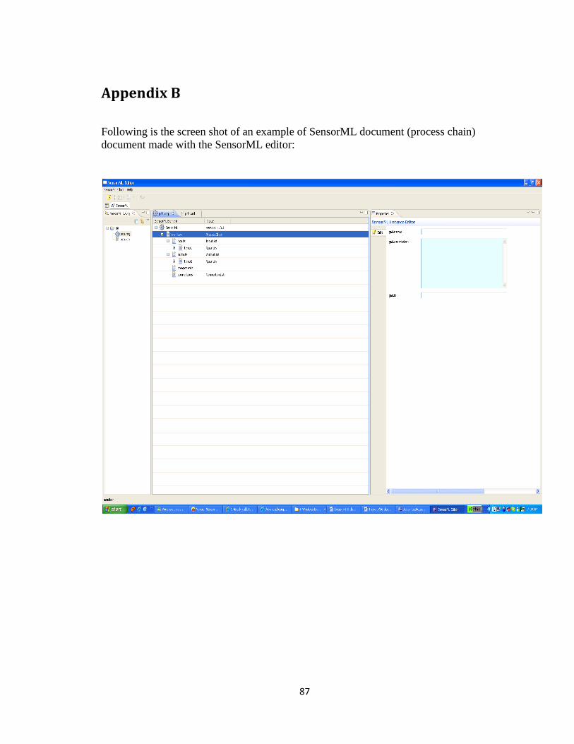
87
Appendix B
Following is the screen shot of an example of SensorML document (process chain)
document made with the SensorML editor:

88
Appendix C
Following are the translator‟s source code:
//*********************************************
//main_class CLASS
//JOB: Main executing class
//*********************************************
import java.io.BufferedReader;
import java.io.BufferedWriter;
import java.io.FileOutputStream;
import java.io.FileWriter;
import java.io.IOException;
import java.io.InputStream;
import java.io.InputStreamReader;
import java.io.PrintStream;
import java.io.PrintWriter;
import java.util.ArrayList;
import java.util.logging.Level;
import java.util.logging.Logger;
import java.util.Scanner;
import javax.swing.JFrame;
import javax.swing.JOptionPane;
public class main_class {
static long start, end, total;
static int count1 = 0;
public static void main(String[] args) {
start = System.currentTimeMillis();
/*
* try { // TODO Auto-generated method stub new readURL(); }
catch
* (IOException ex) {
*
Logger.getLogger(main_class.class.getName()).log(Level.SEVERE, null,
* ex); }
*/
ArrayList input_class = new ArrayList<String>();
String s = "";
int count = 1;
// System.out.println("Enter path to the process chain: ");
Scanner in = new Scanner(System.in);
// String filename = in.nextLine();
System.out
.println("Enter path to where you want your
files to be created(use two backslashes to seperate directories) : ");
in = new Scanner(System.in);
String filePath = in.nextLine();

89
System.out.println("Enter path to SensorML's Editor
workspace");
String sensorMLWorkspace = in.nextLine();
System.out.println("Enter name of your process chain");
in = new Scanner(System.in);
String pch_name = in.nextLine();
DOMParser_pch dpch = new DOMParser_pch(sensorMLWorkspace +
pch_name);
DOMParser d = null;
int size = dpch.process_models.size();
for (int i = 0; i < size; i++) {
System.out.println(dpch.process_models.get(i).toString());
d = new
DOMParser(dpch.process_models.get(i).toString(), "url.xml");
Integer Count = new Integer(count);
String fname = dpch.process_names.get(i).toString();
createsBean mb = new createsBean(dpch, fname,
filePath, d);
count++;
count1++;
}
}
}
Main_class (Execution class) source code
//*********************************************
//CREATES BEAN CLASS
//JOB: creating Java Beans
//*********************************************
import java.io.*;
import java.util.ArrayList;
import java.util.StringTokenizer;
import java.util.logging.Level;
import java.util.logging.Logger;
import java.sql.*;
/*
* To change this template, choose Tools | Templates
* and open the template in the editor.
*/
/**
*
* @author 100378007
*/
public class createsBean {
String inputDB = "";
String BeanName;
int count_bean = 0;
int count = 0;
int count2 = 0;
// String pk="";
// static String dests = "";
90
// static String dest_var = "";
static ArrayList dests = new ArrayList<String>();
static ArrayList dest_var = new ArrayList<String>();
public createsBean(DOMParser_pch dpch, String name, String
filePath,
DOMParser d) {
FileWriter fstream;
BufferedWriter out = null;
BeanName = name;
try {
// Create file
// fstream = new FileWriter("C:\\kimia\\" + name +
".java");
// fstream = new FileWriter("C:\\TestEvent_Bean\\" +
name +
// ".java");
fstream = new FileWriter(filePath + "\\" + name +
".java");
out = new BufferedWriter(fstream);
// out.write("package Implementation;");
// out.newLine();
out.write("import com.mysql.jdbc.Statement;");
out.newLine();
out.write("import java.sql.*;");
out.newLine();
out.write("import java.beans.PropertyChangeSupport;");
out.newLine();
out.write("import
java.beans.PropertyChangeListener;");
out.newLine();
out.write("import java.beans.PropertyChangeEvent;");
out.newLine();
out.write("import java.io.Serializable;");
out.newLine();
out.write("import java.io.BufferedReader;");
out.newLine();
out.write("import java.io.IOException;");
out.newLine();
out.write("import java.io.InputStream;");
out.newLine();
out.write("import java.io.InputStreamReader;");
out.newLine();
out.write("import java.beans.*;");
out.newLine();
out.write("public class " + name
+ " implements PropertyChangeListener,
Serializable{");
out.newLine();
int count_bean1 = 0;
for (int i = 0; i < dpch.source.size(); i++) {
StringTokenizer stt = new
StringTokenizer(dpch.source.get(i)
.toString(), "/");
String p = stt.nextToken();
91
String p1 = stt.nextToken();
StringTokenizer stt_ = new
StringTokenizer(dpch.destination
.get(i).toString(), "/");
String p_ = stt_.nextToken();
String p1_ = stt_.nextToken();
// System.out.println("process name
"+dpch.process_names.get(i)+" source "+dpch.source.get(i)+" destination:
"+
// dpch.destination.get(i));
if
(!dpch.source.get(i).equals(dpch.destination.get(i))) {
if (p.equals(name)) {
Integer cnt = new
Integer(count_bean1);
out.write(" public static " + p_ + "
b"
+ cnt.toString() + "=new
" + p_ + "();");
out.newLine();
count_bean1++;
}
}
}
for (int i = 0; i < d.input.size(); i++) {
out
.write(d.type.get(i).toString() + "
" + d.input.get(i)
+ ";");
out.newLine();
}
out.write("String manufacturer=" + "\"" +
d.manufacturer + "\""
+ ";");
out.newLine();
out.write("String getManufacturer(){return
manufacturer;}");
out.newLine();
out
.write("String sensorBoard=" + "\"" +
d.sensorBoard + "\""
+ ";");
out.newLine();
out.write("String getSensorBoard(){return
sensorBoard;}");
out.newLine();
out.write("String sensorType=" + "\"" + d.sensorType +
"\"" + ";");
out.newLine();
out.write("String getSensorType(){return
sensorType;}");
out.newLine();
92
out.write("String moteType=" + "\"" + d.moteType +
"\"" + ";");
out.newLine();
out.write("String getMoteType(){return moteType;}");
out.newLine();
out
.write("private PropertyChangeSupport pcs
= new PropertyChangeSupport(this);");
out.newLine();
int count_inputs = 0;
for (int i = 0; i < d.input.size(); i++) {
Integer cnt = new Integer(count_inputs);
out.write("boolean flag" + cnt.toString() +
"=false;");
out.newLine();
count_inputs++;
}
// }
out.write("public " + name + "(){");
out.newLine();
out.write("pcs.addPropertyChangeListener(this);");
out.newLine();
out.write("}");
out.newLine();
// **************************************************
String s = "";
File file = new File(d.method.get(0).toString());
FileInputStream fis = null;
BufferedInputStream bis = null;
DataInputStream dis = null;
try {
fis = new FileInputStream(file);
// Here BufferedInputStream is added for fast
reading.
bis = new BufferedInputStream(fis);
dis = new DataInputStream(bis);
// dis.available() returns 0 if the file does
not have more
// lines.
// String w=dis.readLine();
boolean flag = false;
String w = dis.readLine();
// System.out.println("public void
"+d.method_name);
while (dis.available() != 0) {
// this statement reads the line from the
file and print it
// to
// the console.
if (w.equals("}")) {
out.flush();
out.write("}");
93
out.newLine();
flag = false;
// s += w;
break;
}
else if (flag) {
out.write(w);
out.newLine();
// s += w;
// s+='\n';
} else if (w.equals("public void run(){"))
{
// s += w;
out.write(w);
out.newLine();
flag = true;
}
w = dis.readLine();
}
// while(!dis.readLine().equals("public void
"+d.method_name)){System.out.println("Hello");}
// this statement reads the line from the file
and print it to
// the console.
// dispose all the resources after using them.
fis.close();
bis.close();
dis.close();
} catch (FileNotFoundException e) {
e.printStackTrace();
} catch (IOException e) {
e.printStackTrace();
}
// out.write(s);
// out.newLine();
// **************************************************
out.write("public void
propertyChange(PropertyChangeEvent evt) {");
out.newLine();
count_inputs = 0;
out.write(d.method_name + ";");
out.newLine();
for (int i = 0; i < dpch.source.size(); i++) {
StringTokenizer stt = new
StringTokenizer(dpch.source.get(i)
.toString(), "/");
String p = stt.nextToken();
94
String p1 = stt.nextToken();
StringTokenizer stt_ = new
StringTokenizer(dpch.destination
.get(i).toString(), "/");
String p_ = stt_.nextToken();
String p1_ = stt_.nextToken();
// System.out.println("process name
"+dpch.process_names.get(i)+" source "+dpch.source.get(i)+" destination:
"+
// dpch.destination.get(i));
if
(!dpch.source.get(i).equals(dpch.destination.get(i))) {
if (p.equals(name)) {
Integer cnt = new
Integer(count_bean);
/*
* out.write(p_ + " b" +
cnt.toString() + "=new " + p_ +
* "();"); out.newLine();
*/
out.write("b" + cnt.toString() +
".set" + p1_ + "("
+ p1 + ");");
dests.add(p_);
dest_var.add(p1_);
count_bean++;
out.newLine();
}
}
}
out.newLine();
out.write("}");
out.newLine();
count_inputs = 0;
for (int i = 0; i < d.input.size(); i++) {
out.write("public void set" + d.input.get(i) +
"("
+ d.type.get(i).toString() + "
in){");
out.newLine();
Integer cnt = new Integer(count_inputs);
out.write("if (!flag" + cnt + ")");
count_inputs++;
out.newLine();
out.write("flag" + cnt + "=true;");
out.newLine();
out.write(d.type.get(i) + " old=" +
d.input.get(i) + ";");
out.newLine();
out.write(d.input.get(i) + "=in;");
out.newLine();
out.write("pcs.firePropertyChange(" + "\""
95
+ d.input.get(i).toString() + "\"" +
", old,"
+ d.input.get(i).toString() + ");");
out.newLine();
out.write("}");// end of set
out.newLine();
}// end of for
out.newLine();
for (int i = 0; i < d.input.size(); i++) {
out.write("public double get" + d.input.get(i) +
"(){return "
+ d.input.get(i) + ";}");
out.newLine();
}
out.write("}");// end of class
} catch (Exception ex) {
} finally {
try {
out.close();
} catch (IOException ex) {
//
Logger.getLogger(createBeans.class.getName()).log(Level.SEVERE,
// null, ex);
}
}
}
}
Class createsBean Source code //*********************************************
//DOMParser_pch
//JOB: extract process chain information
//*********************************************
import java.io.File;
import java.io.IOException;
import java.util.ArrayList;
import javax.xml.parsers.DocumentBuilderFactory;
import javax.xml.parsers.ParserConfigurationException;
import javax.xml.transform.OutputKeys;
import javax.xml.transform.Result;
import javax.xml.transform.Source;
import javax.xml.transform.Transformer;
import javax.xml.transform.TransformerConfigurationException;
import javax.xml.transform.TransformerException;
import javax.xml.transform.TransformerFactory;
import javax.xml.transform.TransformerFactoryConfigurationError;
import javax.xml.transform.dom.DOMSource;
import javax.xml.transform.stream.StreamResult;
import org.omg.CosNaming.NamingContextExtPackage.AddressHelper;
import org.w3c.dom.Document;
96
import org.w3c.dom.Node;
import org.w3c.dom.NodeList;
import org.xml.sax.SAXException;
public class DOMParser_pch {
ArrayList process_models = new ArrayList<String>();
ArrayList type = new ArrayList<String>();
ArrayList process_names = new ArrayList<String>();
ArrayList source = new ArrayList<String>();
ArrayList destination = new ArrayList<String>();
boolean lngt = false;
String longitude;
boolean lat = false;
String latitude;
boolean alt = false;
String altitude;
int j = 0;
double n1 = 0;
int count = 0;
private Document doc = null;
private Document doc1 = null;
public DOMParser_pch(String filename) {
try {
doc = parserXML(new File(filename));
visit(doc, 0);
} catch (Exception error) {
error.printStackTrace();
}
}
public void visit(Node node, int level) {
double calibvalue = 10;
NodeList nl = node.getChildNodes();
for (int i = 0, cnt = nl.getLength(); i < cnt; i++) {
if
((nl.item(i).getNodeName().equals("sml:component"))) {
process_models.add(nl.item(i).getAttributes().getNamedItem(
"xlink:href").getNodeValue());
process_names.add(nl.item(i).getAttributes().getNamedItem(
"name").getNodeValue());
//
System.out.println(nl.item(i).getAttributes().getNamedItem("location").g
etNodeValue());
// System.out.println(process_models.get(j));
// j++;
} else if
((nl.item(i).getNodeName().equals("sml:source"))) {
source.add(nl.item(i).getAttributes().getNamedItem("ref")
.getNodeValue());
97
} else if
((nl.item(i).getNodeName().equals("sml:destination"))) {
destination.add(nl.item(i).getAttributes().getNamedItem("ref")
.getNodeValue());
} else if ((lngt)
&&
(nl.item(i).getNodeName().equals("swe:Quantity"))) {
lngt = false;
longitude = nl.item(i).getTextContent();
System.out.println(nl.item(i).getTextContent());
} else if ((lat)
&&
(nl.item(i).getNodeName().equals("swe:Quantity"))) {
lat = false;
latitude = nl.item(i).getTextContent();
System.out.println(nl.item(i).getTextContent());
} else if ((alt)
&&
(nl.item(i).getNodeName().equals("swe:Quantity"))) {
alt = false;
altitude = nl.item(i).getTextContent();
System.out.println(nl.item(i).getTextContent());
} else if
((nl.item(i).getNodeName().equals("swe:coordinate"))) {
if
(nl.item(i).getAttributes().getNamedItem("name")
.getNodeValue().equals("longitude"))
lngt = true;
else if
(nl.item(i).getAttributes().getNamedItem("name")
.getNodeValue().equals("latitude"))
lat = true;
else if
(nl.item(i).getAttributes().getNamedItem("name")
.getNodeValue().equals("altitude"))
alt = true;
System.out.println(nl.item(i).getAttributes().getNamedItem(
"name").getNodeValue());
}
/*
* else
*
if((lngt)&&(nl.item(i).getNodeName().equals("swe:Quantity"))) {
* longitude=nl.item(i).getTextContent(); } else if
*
((nl.item(i).getNodeName().equals("swe:coordinate"))) {
* //if(nl.item
*
(i).getAttributes().getNamedItem("definition").getNodeValue
* ().equals("urn:ogc:def:phenomenon:latitude")) //
* System.out.println
* (nl.item(i).getAttributes().getNamedItem("axisCode"
* ).getNodeValue()); if
98
*
(nl.item(i).getAttributes().getNamedItem("swe:Quantity")
* .getNodeValue().equals("longitude")) lngt=true; }
*/
visit(nl.item(i), level + 1);
}
}
public Document parserXML(File file) throws SAXException,
IOException,
ParserConfigurationException {
return
DocumentBuilderFactory.newInstance().newDocumentBuilder().parse(
file);
}
/*
* public static void main(String[] args) { new DOMParser(); }
*/
}
//*********************************************
//DOMParser
//JOB: extract the process model information
//*********************************************
import java.io.BufferedInputStream;
import java.io.BufferedWriter;
import java.io.DataInputStream;
import java.io.File;
import java.io.FileWriter;
import java.io.IOException;
import java.io.InputStream;
import java.net.MalformedURLException;
import java.net.URL;
import java.util.ArrayList;
import java.util.StringTokenizer;
import java.util.concurrent.CountDownLatch;
import javax.xml.parsers.DocumentBuilderFactory;
import javax.xml.parsers.ParserConfigurationException;
import javax.xml.transform.OutputKeys;
import javax.xml.transform.Result;
import javax.xml.transform.Source;
import javax.xml.transform.Transformer;
import javax.xml.transform.TransformerConfigurationException;
import javax.xml.transform.TransformerException;
import javax.xml.transform.TransformerFactory;
import javax.xml.transform.TransformerFactoryConfigurationError;
import javax.xml.transform.dom.DOMSource;
import javax.xml.transform.stream.StreamResult;
import org.omg.CosNaming.NamingContextExtPackage.AddressHelper;
import org.w3c.dom.Document;
import org.w3c.dom.Node;
import org.w3c.dom.NodeList;
import org.xml.sax.SAXException;

99
public class DOMParser {
boolean manufact = false;
boolean snsBrd = false;
boolean mtType = false;
boolean snsType = false;
String manufacturer;
String sensorBoard;
String moteType;
String sensorType;
boolean flag_id = false;
boolean flag = false;
ArrayList input = new ArrayList<String>();
ArrayList type = new ArrayList<String>();
double n1 = 0;
int count = 0;
ArrayList method = new ArrayList<String>();
String method_name = "";
private Document doc = null;
private Document doc1 = null;
private int count_method = 0;
String workspace;
// readURL url;
public DOMParser(String filename,String workspace) {
method_name="run()";
try {
this.workspace=workspace;
// doc1 = parserXML(new
// File("D:\\My Documents\\sensors\\code\\pch.xml"));
doc = parserXML(new File(filename));
// for(int i=0; i<5;i++)
// a.add(new ArrayList());
visit(doc, 0);
} catch (Exception error) {
error.printStackTrace();
}
}
public void visit(Node node, int level) {
String unit_tokenize = "";
double calibvalue = 10;
NodeList nl = node.getChildNodes();
String t = "";
for (int i = 0, cnt = nl.getLength(); i < cnt; i++) {
if ((nl.item(i).getNodeName().equals("sml:input"))) {
input.add(nl.item(i).getAttributes().getNamedItem("name")
.getNodeValue());
type.add("double");
}
//swe:uom
100
/*else if
((nl.item(i).getNodeName().equals("swe:uom")))
{
t=nl.item(i).getAttributes().getNamedItem("xlink:href")
.getNodeValue();
DOMParser_URL dURL = new
DOMParser_URL(workspace, t);
type.add(dURL.unit);
}*/
else if
((nl.item(i).getNodeName().equals("sml:method"))) {
method.add(nl.item(i).getAttributes().getNamedItem("xlink:href")
.getNodeValue());
count_method++;
method_name = "run()";
} else if ((flag_id)
&&
nl.item(i).getNodeName().equals("sml:value")) {
flag_id = false;
if (manufact) {
manufacturer =
nl.item(i).getTextContent();
manufact = false;
} else if (mtType) {
moteType = nl.item(i).getTextContent();
mtType = false;
} else if (snsType) {
sensorType = nl.item(i).getTextContent();
snsType = false;
} else if (snsBrd) {
sensorBoard = nl.item(i).getTextContent();
snsBrd = false;
}
System.out.println(nl.item(i).getTextContent());
} else if
((nl.item(i).getNodeName().equals("sml:identifier"))
||
(nl.item(i).getNodeName().equals("sml:classifier"))) {
System.out.println(nl.item(i).getAttributes().getNamedItem(
"name").getNodeValue()
+ ": ");
101
if
(nl.item(i).getAttributes().getNamedItem("name")
.getNodeValue().equals("Manufacturer"))
manufact = true;
else if
(nl.item(i).getAttributes().getNamedItem("name")
.getNodeValue().equals("Mote Type"))
mtType = true;
else if
(nl.item(i).getAttributes().getNamedItem("name")
.getNodeValue().equals("sensor
Type"))
snsType = true;
else if
(nl.item(i).getAttributes().getNamedItem("name")
.getNodeValue().equals("Sensor
Board"))
snsBrd = true;
flag_id = true;
}
// sml:method
visit(nl.item(i), level + 1);
}
}
public Document parserXML(File file) throws SAXException,
IOException,
ParserConfigurationException {
return
DocumentBuilderFactory.newInstance().newDocumentBuilder().parse(
file);
}
/*
* public static void main(String[] args) { new DOMParser(); }
*/
}
Class DOMParser Source Code
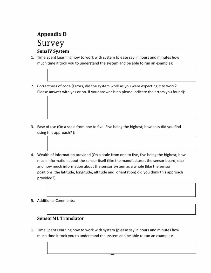
102
Appendix D
Survey SensIV System
1. Time Spent Learning how to work with system (please say in hours and minutes how
much time it took you to understand the system and be able to run an example):
2. Correctness of code (Errors, did the system work as you were expecting it to work?
Please answer with yes or no. if your answer is no please indicate the errors you found):
3. Ease of use (On a scale from one to five. Five being the highest; how easy did you find
using this approach? ):
4. Wealth of information provided (On a scale from one to five, five being the highest; how
much information about the sensor itself (like the manufacturer, the sensor board, etc)
and how much information about the sensor system as a whole (like the sensor
positions, the latitude, longitude, altitude and orientation) did you think this approach
provided?)
5. Additional Comments:
SensorML Translator
1. Time Spent Learning how to work with system (please say in hours and minutes how
much time it took you to understand the system and be able to run an example):

103
2. Correctness of code (Errors, did the system work as you were expecting it to work?
Please answer with yes or no. if your answer is no please indicate the errors you found):
3. Ease of use (On a scale from one to five, five being the highest; how easy did you find
using this system? ):
4. Wealth of information provided (On a scale from one to five, five being the highest; how
much information about the sensor itself (like the manufacturer, the sensor board, etc)
and how much information about the sensor system as a whole (like the sensor
positions, the latitude, longitude, altitude and orientation) did you think this system
provided?)
5. Additional Comments:

104
Appendix E
1. Users with knowledge of SensIV but with no knowledge of the
SCT.
a. First user’s answers:
SensIV System
Time Spent Learning how to work with system (please say in hours and minutes
how much time it took you to understand the system and be able to run an
example):
It took so much time to get start with. And the user must familiar with JAVA as well.
Correctness of code (Errors, did the system work as you were expecting it to
work? Please answer with yes or no. if your answer is no please indicate the
errors you found):
It gave me some errors and I guess that’s completely normal. Because I wrote a new
program and each new program or module creates new bugs into system. So tracking
down those bugs will take some time.
Ease of use (On a scale from one to five. Five being the highest; how easy did you
find using this approach? ):
I’ve been working on SensIV for past 2 years and I should say that getting familiar with
SensIV is time consuming.
Wealth of information provided (On a scale from one to five, five being the
highest; how much information about the sensor itself (like the manufacturer,
the sensor board, etc) and how much information about the sensor system as a
whole (like the sensor positions, the latitude, longitude, altitude and orientation)
did you think this approach provided?)
Adding new types of sensor into the system is real pain. The programmer and developer
must know exactly what they are doing and the documentation of the new sensor must
be provided.
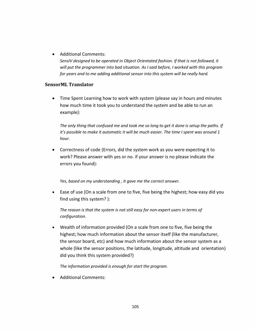
105
Additional Comments:
SensIV designed to be operated in Object Orientated fashion. If that is not followed, it
will put the programmer into bad situation. As I said before, I worked with this program
for years and to me adding additional sensor into this system will be really hard.
SensorML Translator
Time Spent Learning how to work with system (please say in hours and minutes
how much time it took you to understand the system and be able to run an
example):
The only thing that confused me and took me so long to get it done is setup the paths. If
it’s possible to make it automatic it will be much easier. The time I spent was around 1
hour.
Correctness of code (Errors, did the system work as you were expecting it to
work? Please answer with yes or no. if your answer is no please indicate the
errors you found):
Yes, based on my understanding , it gave me the correct answer.
Ease of use (On a scale from one to five, five being the highest; how easy did you
find using this system? ):
The reason is that the system is not still easy for non-expert users in terms of
configuration.
Wealth of information provided (On a scale from one to five, five being the
highest; how much information about the sensor itself (like the manufacturer,
the sensor board, etc) and how much information about the sensor system as a
whole (like the sensor positions, the latitude, longitude, altitude and orientation)
did you think this system provided?)
The information provided is enough for start the program.
Additional Comments:

106
The only thing that caught my attention was pre-configuration of the system. I’d like to
see a better design to deal with configuration, and I’d like to see if it is possible to fix the
path variables.
b. Second user’s answers:
SensIV System
Hours Spent Learning how to work with system (Please also include ease of
learning):
1 hour to understand
Lines of Code written to Change system:
int[] myReadings_Humidity =
FruitSalad.getHmd(wrmsg.getReadings2(),
Constants.READ_NORMAL, Constants.MTS310);
double[] myRealReadings_hmd = new double[]
{conv.GetHumidity(myReadings_Humidity[0]),conv.GetHumidity(myReadi
ngs_Humidity[1]),conv.GetHumidity(myReadings_Humidity[2])
conv.GetHumidity(myReadings_Humidity[3]) };
Correctness of code (Errors, did the system work as you were expecting it to
work?):
It does work, however it is difficult to add new sensors and new event of the each
sensor. A lot of changes at the code.
Ease of use:
Wealth of information provided (How much information did you think each system
provided and which one did you prefer. Why?)
Additional Comments:

107
SensorML Translator
Hours Spent Learning how to work with system (Please also include ease of
learning):
30 mins of explanation from the programmer.
Lines of Code written to Change system:
public static void main(String[] args) {
Temperature b1 = new Temperature();
Temperature1 b2=new Temperature1();
b1.setTemp1(12.3);
b2.setTemp2(23.4);
Correctness of code (Errors, did the system work as you were expecting it to
work?):
The systems works as it expected to work. The system enables adding the following :
New Sensors.
New events of the sensors
Ease of use:
Modeling the sensor
Adding new sensors
Tracking the tool chain of the process
Add new process without changing the code
Wealth of information provided (How much information did you think each
system provided and which one did you prefer. Why?)
Mote Type
Sensor Type
Sensor Board
Sensor Manufacturer
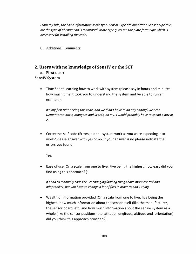
108
From my side, the basic information Mote type, Sensor Type are important. Sensor type tells
me the type of phenomena is monitored. Mote type gives me the plate form type which is
necessary for installing the code.
6. Additional Comments:
2. Users with no knowledge of SensIV or the SCT a. First user:
SensIV System
Time Spent Learning how to work with system (please say in hours and minutes
how much time it took you to understand the system and be able to run an
example):
It’s my first time seeing this code, and we didn’t have to do any editing? Just ran
DemoMotes. Kiwis, mangoes and lizards, oh my! I would probably have to spend a day or
2…
Correctness of code (Errors, did the system work as you were expecting it to
work? Please answer with yes or no. if your answer is no please indicate the
errors you found):
Yes.
Ease of use (On a scale from one to five. Five being the highest; how easy did you
find using this approach? ):
If I had to manually code this: 2; changing/adding things have more control and
adaptability, but you have to change a lot of files in order to add 1 thing.
Wealth of information provided (On a scale from one to five, five being the
highest; how much information about the sensor itself (like the manufacturer,
the sensor board, etc) and how much information about the sensor system as a
whole (like the sensor positions, the latitude, longitude, altitude and orientation)
did you think this approach provided?)
109
1? I didn’t see any of this information other than Temperature and Humidity.
Additional Comments:
I downloaded, I saw, I ran.
SensorML Translator
Time Spent Learning how to work with system (please say in hours and minutes
how much time it took you to understand the system and be able to run an
example):
30 mins
Correctness of code (Errors, did the system work as you were expecting it to
work? Please answer with yes or no. if your answer is no please indicate the
errors you found):
Yes.
Ease of use (On a scale from one to five, five being the highest; how easy did you
find using this system? ):
3.85
Wealth of information provided (On a scale from one to five, five being the
highest; how much information about the sensor itself (like the manufacturer,
the sensor board, etc) and how much information about the sensor system as a
whole (like the sensor positions, the latitude, longitude, altitude and orientation)
did you think this system provided?)
3; I know the manufacturer and board type…but no other information is given
immediately in Eclipse output? Was I required to manually check the XML?
Additional Comments:

110
Fun stuff, but still requires Eclipse?
b. Second user:
SensIV System
Time Spent Learning how to work with system (please say in hours and minutes
how much time it took you to understand the system and be able to run an
example):
It has taken me around 40 minutes I would say to get an understanding of what it is all
about but there are certain confusions.
Correctness of code (Errors, did the system work as you were expecting it to
work? Please answer with yes or no. if your answer is no please indicate the
errors you found):
I did not encounter any error and one I encounter was fixed easily.
Ease of use (On a scale from one to five. Five being the highest; how easy did you
find using this approach? ):
3
Wealth of information provided (On a scale from one to five, five being the
highest; how much information about the sensor itself (like the manufacturer,
the sensor board, etc) and how much information about the sensor system as a
whole (like the sensor positions, the latitude, longitude, altitude and orientation)
did you think this approach provided?)
Information about the sensor board and manufacturer : 4
Sensor positions etc: 4
Additional Comments:
111
I did not have much about idea about the SensIV but after some discussion I got to know.
I am still not so familiar with the system so don’t have much to comment on. But for
somebody who does not know the system and is completely new to it a little more
explanation is desirable.
SensorML Translator
Time Spent Learning how to work with system (please say in hours and minutes
how much time it took you to understand the system and be able to run an
example):
45 min
Correctness of code (Errors, did the system work as you were expecting it to
work? Please answer with yes or no. if your answer is no please indicate the
errors you found):
Just a few findings like upon minimizing the sensorml editor closes and the ctrl + A
doesn’t work on the text fields. If these are some things which need to be worked on and
fixed should be done.The system does seem to work fine.
Ease of use (On a scale from one to five, five being the highest; how easy did you
find using this system? ):
4.
Wealth of information provided (On a scale from one to five, five being the
highest; how much information about the sensor itself (like the manufacturer,
the sensor board, etc) and how much information about the sensor system as a
whole (like the sensor positions, the latitude, longitude, altitude and orientation)
did you think this system provided?)
5
Additional Comments:
112
I am impressed with the amount of effort put in and it seems to be a really good system
making the developers and users life easy. A good documentation explaining the purpose
of the system and the other details should be shared so that the user finds it easier to
understand.
Good Luck!
3. Users with knowledge of SensIV and of the SCT
SensIV System
Time Spent Learning how to work with system (please say in hours and minutes
how much time it took you to understand the system and be able to run an
example):
About 1 hr
Correctness of code (Errors, did the system work as you were expecting it to
work? Please answer with yes or no. if your answer is no please indicate the
errors you found):
Yes.
Ease of use (On a scale from one to five. Five being the highest; how easy did you
find using this approach? ):
3.
Wealth of information provided (On a scale from one to five, five being the
highest; how much information about the sensor itself (like the manufacturer,
the sensor board, etc) and how much information about the sensor system as a
whole (like the sensor positions, the latitude, longitude, altitude and orientation)
did you think this approach provided?)
1.
Additional Comments:
113
Since clear examples were presented in the code and instructions were available on how
to add a sensor to Sensiv it was relatively straight forward but I was not certain what I
was doing since I did not study the code before the session.
SensorML Translator
Time Spent Learning how to work with system (please say in hours and minutes
how much time it took you to understand the system and be able to run an
example):
1hr.
Correctness of code (Errors, did the system work as you were expecting it to
work? lease answer with yes or no. if your answer is no please indicate the errors
you found):
Yes.
Ease of use (On a scale from one to five, five being the highest; how easy did you
find using this system? ):
4.
Wealth of information provided (On a scale from one to five, five being the
highest; how much information about the sensor itself (like the manufacturer,
the sensor board, etc) and how much information about the sensor system as a
whole (like the sensor positions, the latitude, longitude, altitude and orientation)
did you think this system provided?)
3.5.
Additional Comments:
Understanding SensorML is much simpler than Sensiv but I received a number of errors
from the existing link references because I did not name my project BR.

114