Embed Size (px)
Citation preview
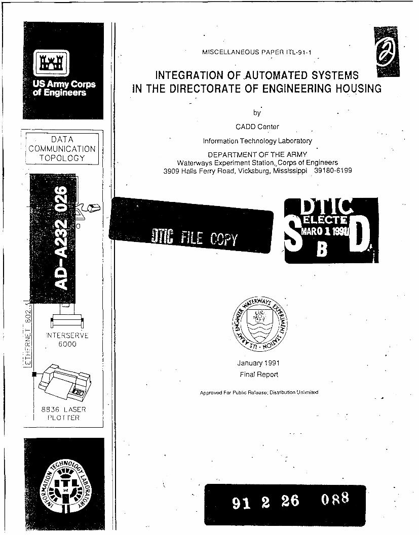
MISCELLANEOUS PAPER ITL-91-1
INTEGRATION OF AUTOMATED SYSTEMSIN THE DIRECTORATE OF ENGINEERING HOUSING
by
CADD Center
DATA Information Technology LaboratoryCOMMUNICATION
C OMMU OY DEPARTMENT OF THE ARMYTOPOLOGY Waterways Experiment Station,,Corps of Engineers
3909 Halls Ferry Road, Vicksburg, Mississippi 39180-6199
9WA),
INTERSERVE MA6000
January 1991
Final Report
Approved For Public Roloaso; Distribution Unlimited
8836 LASERPLOTTER
0M0
s
Destroy this report when no longer needed. Do not returnit to the originator.
The findings in this report are not to be construed as an officialDepartment of the Army position unless so designated
by other authorized documents.
The contents of this report are not to be used foradvertising, publication, or promotional purposes.Citation of trade names does not constitute anofficial endorsement or approval of the use of
such commercial products.
Form AWovedREPORT DOCUMENTATION PAGE OM No. 704o-o
Puic reporting burden for this collection of information is estimated to average I hour per response. includlng the time for reviewing instructios. ,earching existing data tources.gather tand ainai i a nd omletn and reviewi the collection of information. Send comments regardng this brdk estimate or any other asect of thiscollection Of nformat~~on . including su0ge*tions for recig this burden to Washington Headquarters Services, Oirecworate for information Operations and Aeports. 12 IS JefersonOavs Highway. Suite 1204. Arlington. VA 2202-4302. and tO the Office of Management and Budget, Paperwork Reduction P rojec (0704-0186). Washington , Dc 2050.
1. AGENCY USE ONLY (Leave blank) 2. REPORT DATE 3. REPORT TYPE AND DATES COVEREDI January 1991 Final report
4. TITLE AND SUBTITLE S. FUNDING NUMBERS
Integration of Automated Systems in the Directorate
of Engineering Housing
6. AUTHORS)
7. PERFORMING ORGANIZATION NAME(S) AND ADORESS(ES) 8. PERFORMING ORGANIZATION
USAE Waterways Experiment Station, Information REPORT NUMBER
Technology Laboratory, 3909 Halls Ferry Road, Miscellaneous Paper
Vicksburg, MS 39180-6199 ITL-91-1
9. SPONSORINGIMONITORING AGENCY NAME(S) AND AOORESS(ES) 10. SPONSORING/MONITORINGAGENCY REPORT NUMBER
11. SUPPLEMENTARY NOTESAvailable from National Technical Information Service, 5205 Port Royal Road,
Springfield, VA 22161.
i2a. DISTRIBUTION /AVAILABILITY STATEMENT 12b. DISTRIBUTION CODE
Approved for public release; distribution unlimited
13. ABSTRACT (Maximum 200 words)This report recommends particular configurations of hardware and software
for small, medium, and large Directorates of Engineering and Housing (DEH)
offices. It also contains various other features of an integrated system in-
cluding telecommunications, database management, and interaction between of-
fices and disciplines.
The DEH Special Advisory Task Group (SATG) is an advisory task group of
the Computer-Aided Design and Drafting Center (CADD) located in the Information
Technology Laboratory at the US Army Engineer Waterways Experiment Station. It
is organized to better inform the DEH community about CADD, transfer CADD
knowledge contained within the Corps and to the DEH community, and to provide
the CADD Center and other Corps offices information on how to better service
DEH needs regarding CADD.
14. SUBJECT TERMS 15. NUMBER OF PAGES
2116. PRICE CODE
17. SECURITY CLASSIFICATION 16. SECURITY CLASSIFICATION 19. SECURITY CLASSIFICATION 20. LIMITATION OF ABSTRACTOF REPORT OF THIS PAGE OF ABSTRACTUNCLASSIFIED UNCLASSIFIED I I _I
NSN 7S40-01-280-5500 Standard Form 298 (Rev 2-89)Prescribed by ANSI Std 139.18298-102
PREFACE
This documents describes the methods by which theDirectorates of Engineering and Housing (DEH) should integrateexisting automation systems. Specifically this documentdiscusses the integration of Computer-Aided Design and Drafting(CADD) equipment with the Arm s corporate database (IFS-M) andother programs such as RPLANS, HOMES, and the EMS systems. Astandard hardware system configuration for a small system and amedium-large system is recommended. A standard non-graphicdatabase software application and the acceptance of theEngineering Manual "Standards Manual for U.S. Army Corps ofEngineers Computer-Aided Design and Drafting (CADD) Systems" arealso addressed.
The authors of this report, members of the DEH SpecialAdvisory Task Group (SATG) sub-committee on Integration, were:
Mr. Ron Niemi, CEHSC (chairman)Dr. Sine Farrell, CERLMs. Debra Brinager, CERLMr. Gerald McClintock, USAREURMr. Owen Estes, Fort RileyMr. Khiem Luu, EHSCMr. Carl Stephens, WES, Chief CADD CenterCPT Bob Felix, WES
Work on this document was performed under the direction ofDr. N. Radhakrishnan, Chief, Information Technology Laboratory,US Army Engineer Waterways Experiment Station (WES), and Dr.Edward Middleton, Chief, Computer-Aided Engineering Division.
Commander and Director of WES was COL Larry B. Fulton.Technical Director was Dr. Robert W. Whalin.
01,10
Acceuion ForNTIS GRA&IDTIC TAB 0Unannounced 0Justificatio-
ByDistribution/ __
Availability CodesAvail Ajor
IDiat Special
TABLE OF CONTENTS
PREFACE ...................... . . i
INTRODUCTION . . . .... .............. . . . .. 1
DEFINING GRAPHICS AND NON-GRAPHICS .. . . . . . . 2
INTEGRATION -- HARDWARE STANDARDS .. .......... 4
CADD System Platform Standards . ...... 4Connectivity Architecture Standards ... ...... 6
INTEGRATION -- SOFTWARE STANDARDS ... .... .......... 9
INTEGRATION -- GRAPHIC DATABASE STANDARDS . . . ... 10
INTEGRATION -- NON-GRAPHIC DATABASE STANDARDS .1.. 1
STANDARD OBJECTIVES ....... ................ 13
SUMMARY AND RECOMMENDATIONS .... ............. 13
ii
INTRODUCTION
This paper discusses the need to integrate the variousindividual automated systems in the Directorate of Engineeringand Housing (DEH). The concept is to share common data in acentral database, thereby reducing the duplication of data thatexists between current and in-bound systems. This paper alsorecommends a standard CADD hardware architecture forinstallations, Corps of Engineer CADD standards, and a standarddatabase software.
The Directorates of Engineering and Housing (DEHs) on ArmyInstallations are currently facing a most difficult andtremendously challenging period in trying to adequately managetheir numerous missions. Among the most complex tasks toaccomplish even during more prosperous times is informationcoordination, dissemination, and management. The technologicaladvances in computer automation have made these tasks easier,faster, and improved the accuracy of performance. Thesetechnological advances, however, present significant challengesto conquer in order to efficiently and effectively utilize thetechnology.
The concern of the DEH Special Advisory Task Groupsubcommittee on Integration and Standardization is that numerousunrelated and incompatible automated computer programs have beengenerated by a variety of governmental activities and contractorsand several more are programmed or under development. Theseprograms have, by and large, been developed for a specific useand for specific computer platforms with usually little or noregard for compatibility with the DEH automated database ofrecord, the Integrated Facilities System - Mini/Micro (IFS-M).Development of graphics ard non-graphics databases is ongoing atmany DEHs. To date there appears to have been little or nodevelopment towards integration or compatibility between thegraphics and IFS-M databases. The bulk of these graphicdatabases appear to have been developed or are being developed inan Intergraph CADD format.
In today's economic environment, the DEHs are faced withsevere resource restrictions and therefore must focus theirefforts on working smarter than ever before. The DEHs cannotafford to purchase a variety of automated programs operating onmultiple platforms/systems that often provide for duplicateinformation. With limited resources, the DEHs cannot afford tocontinually train numerous personnel on multiple computerplatforms, nor can they afford the cost of the associatedequipment maintenance. The DEHs must, therefore, be capable ofmaximizing their automation capability while minimizing theirinvestment in equipment, personnel training, and equipmentmaintenance.
1
it is not the intent of the DEH SATG subcommittee onIntegration and Standardization to limit automation development,but to promote automation compatibility and standardization byutilization of existing major equipment platforms to the maximumextent possible in developing future automation. Compatibilityand standardization, not only within the DEH activity, but alsobetween the DEHs and the Corps of Engineers, is paramount forefficiently transferring information to meet today's missionrequirements as well as those in the foreseeable future.
DEFINING GRAPHICS AND NON-GRAPHICS
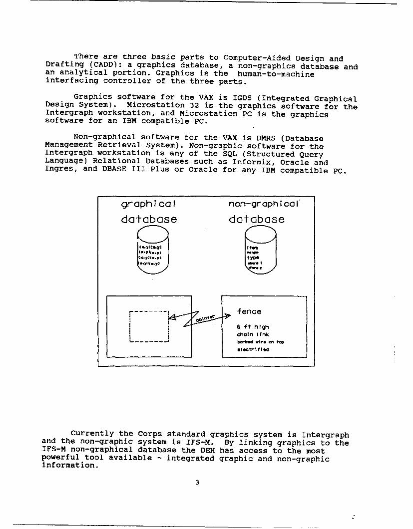
When the user draws a line in any graphical system, thatline is defined with a starting xyz coordinate and an ending xyzcoordinate. The line is further defined by a certain color,weight (or thickness) and style (ie. dotted or dashed line). Allof this information resides in the graphical database for thatparticular line.
That line may represent a fence in the diagram. That fencemay have certain characteristics we need to remember. We don'twant to place those characteristics on the diagram because theywould clutter the picture. Therefore, we place thosecharacteristics in a non-graphical database. CADD has theability to link the two databases together so that we connect thegraphical database to the non-graphical database. What thisallows us to do, while in the graphics mode, is point to the linethat represents a fence and the non-graphical or attributeinformation appears on the screen.
0Z0 ; AH ICS ;R HICS AN.LTICLL< L
-J 0- >-
VAX VMS DS DIMRs ESPRSTAT3~O~NIX MS 32 SOL RD ffCaL [NRAD
I NGRESIBM PC MS -DOS MS PC DBASE III PLUSMAC- S MAC IORACLE WITH MS PC VER.4.O)
2
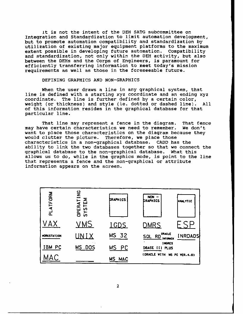
There are three basic parts to Computer-Aided Design andDrafting (CADD): a graphics database, a non-graphics database andan analytical portion. Graphics is the human-to-machineinterfacing controller of the three parts.
Graphics software for the VAX is IGDS (Integrated GraphicalDesign System). Microstation 32 is the graphics software for theIntergraph workstation, and Microstation PC is the graphicssoftware for an IBM compatible PC.
Non-graphical software for the VAX is DMRS (DatabaseManagement Retrieval System). Non-graphic software for theIntergraph workstation is any of the SQL (Structured QueryLanguage) Relational Databases such as Informix, Oracle andIngres, and DBASE III Plus or Oracle for any IBM compatible PC.
graph Ca I non-graphi cal
database database
fence
IX-1f)6 ft holg*11) L + h
chaln IfnkL. .- - barbed wire an top
electrifled
Currently the Corps standard graphics system is Intergraphand the non-graphic system is IFS-M. By linking graphics to theIFS-M non-graphical database the DEH has access to the mostpowerful tool available - integrated graphic and non-graphicinformation.
3
INTEGRATION -- HARDWARE STANDARDS
In pursuit of database integration, hardware and softwarecompatibility issues must be resolved. This section discusseshardware connectivity architecture standards for data sharingbetween graphic and non-graphic based automated informationsystems.
1. CADD System Platform Standards:
a) The current Corps-wide CADD system acquisition programembodies a wide range of products from Intergraph Corporation.This program provides a "total solution" support for theMACOMs/DEHs graphical information processing requirements. The"total solution" concept of a single source for hardware,software, and system support offers certain operationalcompatibilities between MACOMs and DEH organizations.Furthermore, Intergraph products support a distributed dataprocessing capability that is in compliance with theInternational Standards Organization (ISO) Open SystemInterconnect (OSI) Protocols. Intergraph's conformity to theinternational OSI protocols is an advantage for the DEHorganizations when networking to other government host systemsusing the proposed government OSI protocols (GOSIP). Currently,GOSIP is under development and will be based on the OSIstandards.
b) Standard System Configurations: The following CADDsystem configurations are based on Intergraph Corporation andother vendor's products approved for the Corps-wide CADD systemacquisition program (Reference Contract No: DACW87-87-D-0092).The server based system configuration is applicable for medium tolarge DER installations, MACOM DEHs, and HQ DA activities. TheUNIX workstation configuration is applicable for mediuminstallations, and the personal computer system is applicable forsmall DEH's. A recommendation by the DEH SATG subcommittee onIntegration and Standardization is also presented for systemconfiguration purchasing.
1) Server Based System Configuration:
- Main System Processor: 10 MIPS RISC Processor,48 MB Memory, 670 MB Disk Drive, 3 1/2" Floppy Disk Drive, UNIXV, Environment Level V (CLIX), NFS and TCP/IP NetworkingSoftware, and Interplot. Recommend: Interserve 6000 System.
- UNIX Workstation: 19" Color Monitor, 10 MIPSRISC Processor, 16 MB Memory, 180 MB Hard Disk, 3-1/2" FloppyDisk Drive, UNIX V, Environment Level V (CLIX), NFS and TCP/IPNetworking Software, and either a Mouse or Digitizing Cursor andTablet. Recommend: Interpro 6040 Workstation.
4
- Mass Storage Subsystem: Cartridge Tape Drive(QIC 6250 bpi format).
- Output System: Laser Plotter, 400 DPIResolution. Recommend: Versatec 8836 Laser Plotter.
- Recommended CADD System Software: Microstation32, Looking Glass Desktop Manager, DB Access, and RelationalInterface System (RIS) Software (networking version), and ORACLERDBMS.
2) Workstation Based System Configuration:
- Main System Processor: 10 MIPS ClipperProcessor, 16 MB Memory, 180 MB Disk Drive, 3-1/2" Floppy DiskDrive, UNIX V, Environment Level V, NFS and TCP/IP NetworkingSoftware, 19" Color Monitor, Mouse or Digitizing Cursor andTablet. Recommend: Interpro 6040.
- Mass Storage Subsystem: Cartridge Tape Drive(QIC 6250 bpi format).
- Output System: Hewlett-Packard GraphicsLanguage (HPGL) based pen plotter. Recommend: HP 7595 PenPlotter, or if high volume is anticipated, a 400 DPI LaserPlotter, recommend Versatec 8836.
- Recommended CADD System Software: Microstation32, Looking Glass Desktop Manager, DB Access, RelationalInterface System (RIS) Software, and ORACLE.
3) Personal Computer Workstation System Configuration:
- Main System Processor: 19" Color Monitor, 80386or 80486 Processor with Math Coprocessor, 8 MB memory, 120 MBHard Disk, 5-1/4" High Density Floppy Disk Drive, MicroStation PCcompatible high resolution graphics card, Windows 3.0, PC/NFSnetworking software, and mouse or digitizing tablet and cursor.
- Mass Storage Subsystem: Cartridge Tape Drive
- Output System: Hewlett-Packard GraphicsLanguage (HPGL) based pen plotter. Recommend: HP7595 Pen Plotter
- CADD System Software: MicroStation PC, ORACLE
5
2. Connectivity Architecture Standards:
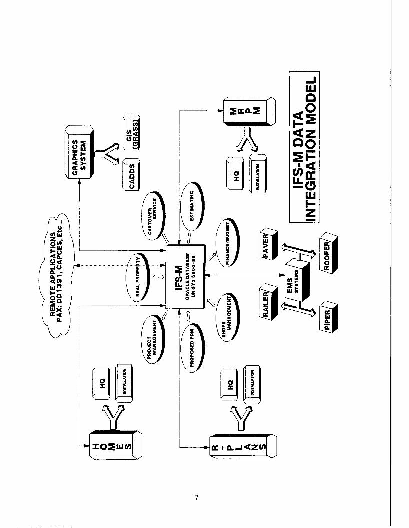
a) The DEH organizations have many diverse operations.These operations are being supported by various ManagementInformation Systems (MIS), such as IFS-M, FESS, HOMES, etc.These MIS systems reside on several types of hardware platformsand maintain their own unique and independent database system.Under the existing configuration, the IFS-M database system hasbeen mandated by DA as the corporate database system to serve allother MISs operated by the DEHs.
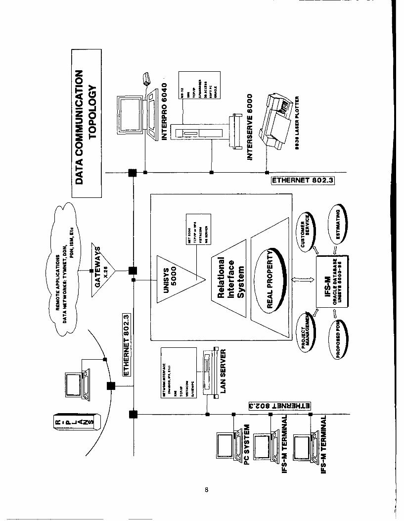
b) A system connectivity architecture is required tostandardize the data distribution and processing tasks betweenthe non-graphical based IFS-M corporate database system, and thegraphical based Intergraph CADD system. The general frameworkfor such connectivity architecture is modeled from three primarynode connectivity groupings: Host Node, Communications Node, andPeripherals Node. The nodes connectivity grouping is necessarybecause of varying system characteristics of each MIS.Connectivity linkage of each group is described as follow:
- Host Node consists of host processors that supplydata, access method, and network control. This group containsthe IFS-M corporate database system operating on the Unisys 5000and Intergraph graphical database operating on the Interpro orthe Interserve systems.
- Communication Node consists of communication andnetwork controllers that provide connectivity between host andworkstation. This group could contain several types of LocalArea Network Systems, i.e., 3Com 3Plus, Banyan Vines, IBMToken-Ring, etc.
- Peripherals Node consists of hardware and softwarethat supports end-user activity. This group contains terminal,workstation, applications software, distributed applications,plotters, etc .
The interoperability between these node connectivity groupsdepends greatly on the selection of a data transport protocol.Currently, the Unisys 5000 platform contains the corporatedatabase and supports the Transport Control Protocol/InternetProtocol (TCP/IP) data transport protocol. Thus, it is crucialthat TCP/IP protocol be implemented as the data transportstandard for all three node connectivity groups in order toattain maximum interoperability between system platforms. TheSATG Integration Sub-Committee recommends that Intergraph'sTCP/IP optional network protocol and file sharing software beimplemented as a standard requirement for all CADD systemconfigurations.
6
-J
Aw 2CCCLuna
0
0 U(0
_ [LiPI-
z lz
2,0. cc
zo~u~w
7R
z0
01 0
Ix
zo au -A
I 00
o 0
U C4 0.
Ni I4 i 4
aa
6~~ lbw
II
00z
I~z IIx4
~II-
0
liz 0
IL£ CO4I
cv8
INTEGRATION -- SOFTWARE STANDARDS
The sharing of common data between the IntegratedFacilities System-Mini/Micro (IFS-M), the numerous stand-aloneDEH related systems such as PAVER, CAMMS, RPLANS etc., and theCADD systems at the installation requires a thorough examinationto determine the plausibility of either total system integrationor interfacing at the data element level. In order to havecompatible systems that can be easily and accurately interfacedto each other, current and future system hardware platforms, thevarious systems to be considered, and their supporting softwaremust be identified and adhered to in the field as "standards".The previous section has described the hardware issues to beconsidered during the integration operation and this sectionoutlines the similar system and software related issues.
The current efforts to integrate CADD systems and othernon-homogeneous DEH related systems are in their infancy.Different systems have been developed for specific installationneeds and have become essential tools for each DEH to conductbusiness. A coordinated effort must be made to interface allthese systems so that they share the same database and dataelements, and can be supported centrally for all differentinstallations.
In their Criteria Search and Analysis Report (Jan 1990) forthe TM 5-803-3 "Automated Map Data Base Standards for ArmyInstallations", Dewberry and Davis summarize their findingsregarding existing systems and applicable software being used inthe field. Most of the systems which are being used by the DEHuse either Dbase III+, Oracle, Intergraph, or AutoCad. In orderfor interfaces to be built and supported at the Army level, allsystems need to be able to share data which is resident in IFS-Mand its Oracle database. In order to accomplish integration,similar software will have to be adopted in the field, and aconcerted effort will have to be made at all levels to developthe interface mechanisms between these packages. Finally, asuccessful technical transfer plan should be developed for eachnew system that identifies and outlines the steps to be taken fordata exchange at the DEH level.
This portion of systems planning and development shouldguarantee that reference has been made to integration orinterface issues to ensure maximum system integration at the DEHlevel. As all systems which are used at the DEH become moreintegrated, and duplication of data entry becomes non-existent, asingle user interface should be developed to minimize the impactof the plurality of systems in use. This user interface shouldbe tailored to the pertinent functional areas necessary for theindividual to perform his/her job in the most efficient andeffective manner. This single user interface implies offering aconsistency of user input which would render the change of system
9
or application transparent to the user. The task of identifyingthe individual system areas for each functional user, and mappingthese requirements into a schema or template, would help in thedevelopment of standard DEH interfaces to all systems. Thecritical task at that point would be to keep these interfaces anduser templates current and expediently distributed to all DEHs.
INTEGRATION -- GRAPHIC DATABASE STANDARDS
A. Defining the graphics database standards
The Corps of Engineers has developed CADD standards throughnumerous Single Discipline Task Groups functioning in the Corps.The immediate benefits of standards are many: consistent qualityproducts, consistent requirements for the local district and A/Edeliverables, and efficiencies derived from organization widesharing of techniques and products. For example, if one districthas to design and construct a barracks for an installation butdo not have a mechanical engineer, they can send the necessaryelectronic drawings to a sister district with a mechanicalengineer. The mechanical engineer can then see what thearchitect and electrical engineers have done and whatever work hedecides to do will be on the correct level and have the correctline weight and style. Sharing drawings or data like this wouldnot be possible if the Corps did not use CADD standards.
Installations have the same need to share information. Anautomated facility management system has the water utilities onone level with the water lines a specific color and line weight.The same is true for each of the other utilities. Each of theother utilities are on a different level from each other and havea different line color and weight. Suppose a water line breaksand is in need of repair. After the repairs are completed, it isnecessary to update the graphic database. By using CADDstandards, the graphics file is easily maintained. The updatingof the graphics file can be done at the foreman's shop thentransferred to the master planning file. The maintaining andsharing would not be possible if CADD standards where not used.
Graphical standards allows the use of "templating" a newdevelopment for one system and having everybody use thattemplate, thereby reducing the cost of creating multipletemplates to achieve the same result. When an installationbegins the development of an automated system, the use ofstandards will reduce the cost of the A/E firm by giving him atemplate to work from. When changes need to be made, the taskbecomes an automated task if standards are used. For example,suppose all the buildings in a drawing file are to be changedfrom level one to level two. A user command can be written asthe template and the task is done automatically. On the otherhand, if standards are not used each change becomes a majormanual task.
10
B. Defining the CADD Standards
CADD standards define the exact level, line code, lineweight and line color for each graphical entity in a drawing.For example, buildings and large structures are on level 4 andhave a line code of 0, a line weight of 2 and a line color of 4.Roads and parking lots are on level 8 and have a line code of 0,line weight of 2 and a line color of 6. Landscape planting is onlevel 21 and has a line code of 0, a line weight of 2 and a linecolor of 2.
The DEH SATG subcommittee on Integration and Standards hasreviewed the Dewberry and Davis "Automated Map Data Base Standardfor Army Installations" contract efforts, as well as the WESefforts to define CADD standards. The sub-committee recommendsthat the standards (symbology, line weight, colors, levels, etc)being proposed by the WES CADD Center (as recognized by theDewberry and Davis study) be evaluated by a DEH with strong CADDexperience. The subcommittee also recommends that the SATGchoose the DEH, and further, funding for this effort should beprovided by the SATG.
INTEGRATION -- NON-GRAPHIC DATABASE STANDARDS
A. Defining the Non-Graphics Database Standard
Currently there exists many different kinds of non-graphicdatabases being used in the DEH. In the CADD environment, thenon-graphic database software is generally determined by the typeof workstation used. The VAX based Intergraph workstation usesthe database package, Data Management and Retrieval System(DMRS), which is part of the core software delivered byIntergraph on the Corps contract. Typically, Informix and ORACLEare the non-graphic databases used with the Microstation 32 UNIX-based workstations, DBASE III/III+ is used with the P.C. DOS-based workstations. There are other non-graphic databases usedwith both of the workstations, but the software noted above seemto be the most common.
A non-graphic database standard should be established tofacilitate the sharing of information between different factionsand systems within the DEH and eliminate like-data residing ondifferent databases. Standardized fields and data attributesshould be developed so that other applications and/or systems caninterface transparently with the standard database's environment.
The DEH SATG subcommittee on Integration and Standardsrecommends that the relational database ORACLE become thenon-graphic database standard for the workstation environment.The prevailing factors that contributed to this recommendationare as follows: a) ORACLE database software can be used with theMicrostation 32 workstation, b) ORACLE provides flexibility in
11
that it can run on different platforms and operating systems, c)ORACLE was the database chosen for several standard Army systemscurrently in development or deployment (i.e., IntegratedFacilities System - Mini/Micro, IFS-M) and d) ORACLE is fastbecoming an "industry standard".
B. Defining the Standardized Data Fields/Elements
With a standard database defined, standardized datafields/elements can be defined. Since IFS-M tracks all RealProperty Maintenance Activities, it seems logical to use IFS-M'sdata elements as the "templates" from which standards can bedeveloped. These non-graphics standards would facilitate thetask of non-homogeneous system integration at the data elementlevel. The standards would dictate data element attributes suchas field name, length, and alpha-numeric designation, and wouldguide system developers to match their system data with that ofIFS-M's. In this way, total system integration at the dataelement level is accomplished.
A case in point: there are currently data elements inUSAREUR's Master Planning database that have a counterpart inIFS-M. The USAREUR's data element name and associated attributesmay be different but the functional description of the dataelement matches IFS-M's description.
Some examples of common structural data elements from thetwo databases are listed below:
USAREUR Data element IFS-M Data ElementINSTALL_NO INSTALLATION_NUMBERINSTALL_NAM INSTALLATION_NAMEIFS_FAC_NO FACILITY_NAMECATCODE CATEGORY_CODE
The above data elements have different attributes assignedto them in each system however they are synonymous inapplication. There is no need for the above information to residein two databases. Thus, if the USAREUR data elements weredefined with the same attributes as IFS-M, the information couldreside on IFS-M and be linked to the CADD database when needed.This would also alleviate duplicate data taking up critical diskspace on the CADD system.
The above constitutes only a small part of the dataelements that have been identified as common between CADD -databases and IFS-M. It is not within the scope of this paper toidentify and catalog all the common data elements between them.
12
STANDARD OBJECTIVES
The discussion thus far points out the current trend in theefforts of many organizations to automate the DEH. The DEH hasmany automation systems residing on many different machines.Each machine is designed to perform one specific task. The DEHshould be able to perform his/her job utilizing all availableautomated tools on a single workstation. All automation productsshould be developed with existing Army/ Corps of Engineer/defacto standards (e.g. ORACLE RDBMS, Intergraph, IFS-M, etc.).Efforts should be made to move existing products/ tools into theset standards.
SUMMARY AND RECOMMENDATIONS
The purpose of this document is to recommend standards whichwill aid in the integration of graphics and non-graphics basedsystems. Our goal is to define the hardware, software,telecommunications, and data standards required to provide theDEH with the most effective mix of automated products with whichto accomplish their mission.
1. Medium to Large CADD Systems: We recommend that futureprocurement by medium to large CADD DEH customers be from theCorps contract and use the Intergraph 6000 series server.
2. Small Systems: We have recommended that futureprocurement by small CADD DEH customers be from the Corpscontract and employ the Intergraph 6000 series workstation. Forthose very small DEHs with only a few masterplanning and/ordesign personnel and small budgets, we recommend 80386 or80486-based PCs running MS-DOS, DBASE III and Microstation PC.PC's may also be used in conjunction with UNIX based systemsthrough the use of NFS and PC/NFS.
3. Non-Corps Contract Packages: We feel it is ofparticular importance that use of non-Corps contract graphicspackages should be avoided. Corps automation policy requiresthat the districts/divisions utilize the Corps CADD contract.Since our goal is to facilitate an interface between Corpsdistricts and DEHs and avoid the difficulties encountered whentransferring files between Microstation software and othervendor's products, we strongly recommend that DEHs useonly the Intergraph Microstation graphics software.
4. Telecommunications: In order to improvetelecommunications between all graphics and non-graphicshardware, we recommend the use of the TCP/IP protocols. This ismost important to ensure the easy transition of data between theCADD equipment and the Unisys 5000 based IFS-M.
13
5. Graphic Data Standards: Graphic standards must beadhered to in areas such as CADD symbology, line weights, colors,levels, etc. The SATG is currently involved with the WES CADDCenter's and Dewberry and Davis's efforts in the development ofsuch standards. We recommend a DEH be selected to review andevaluate the Corps of Engineers standards.
6. Non-Graphic Dat2 Standards: Non-graphic data standards,as delineated by the IFS-M data dictionary, must be complied within order to facilitate accessibility by other DEH systems thatshare the same data elements.
Attaining the goal of an integrated graphic and non-graphiccorporate database, the above recommendations must be consideredand implemented in a Corps-wide effort to combine all DEH dataelements into one large database. This will involve a majorcommitment by personnel at all levels since the cost and effortsinvolved will be significant. We should keep in mind theultimate vision of a totally integrated information environmentfor Army and Corps personnel in the year 2000.
14
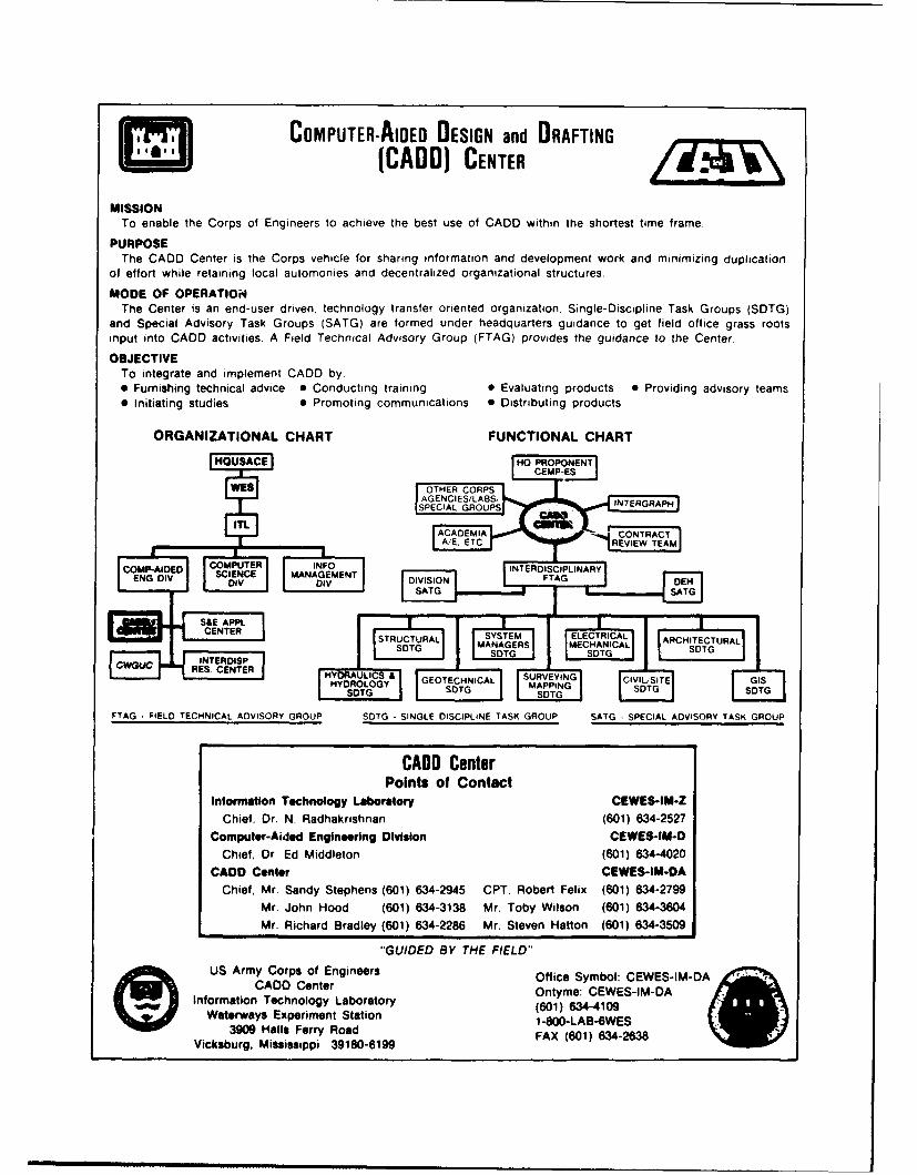
COMPUTER-AIDED DESIGN and DRAFTING(CADD) CENTER
MISSIONTo enable the Corps of Engineers to achieve the best use of CADD within the shortest time frame.
PURPOSEThe CADD Center is the Corps vehicle for sharing information and development work and minimizing duplication
of effort while retaining local automonies and decentralized organizational structures.
MODE OF OPERATIONThe Center is an end-user driven, technology transfer oriented organization Single-Discipline Task Groups (SDTG)
and Special Advisory Task Groups (SATG) are formed under headquarters guidance to get field office grass rootsinput into CADO activities. A Field Technical Advisory Group (FTAG) provides the guidance to the Center.
OBJECTIVETo integrate and implement CADD by:" Furnishing technical advice e Conducting training 0 Evaluating products 0 Providing advisory teams* Initiating studies 0 Promoting communications 0 Distributing products
ORGANIZATIONAL CHART FUNCTIONAL CHART
rH_0_U ~ ~ AD Center HOPRPOEN
In"OrmaCEn TecnoogLortoyWE
CAD CenterSCNTRACT-DIGNIS/~ INTRGAP
ST PETAL GRUSSTM ECRCA
UC . T UR VIE TARCITCUA
"GIE BYV T ER" MA NWatery ExrSnTG t n -INTERDISP ,,T S V
CWGC ESCFTE HYORLC Y GEOTECHNICAL I ISURVEYING CII !
3 Hl F YROG MAPPING
FTAG -FIELD TECHNICAL ADVISORY GROUP STG --SINGLE DISCIPLINE TASK GROUP SATG -SPECIAL AVISORY TASK GROUP
CABO CenterPoints of Contact
Information Technology Laboratory CEWES-IM-Z
Chief, Dr. N. Radhakrishnan (601) 634-2527
Computer-Aidod Engineering Division CEWES-IM-D
Chief, Dr. Ed Middleton (601) 634-4020
CADD Center CEWES-IM-DA
Chief, Mr. Sandy Stephens (601) 634-M95 CPT. Robert Felix (601) 634-2799
Mr. John Hood (601) 634-3138 Mr. Toby Wilson (601) 634-3604
Mr. Richard Bradley (601) 634-2286 Mr. Steven Hatton (601) 634-3509
"GUIDED BY THE FIELD"~US Army Corps of Engineers Office Symbol: CEWES-IM-DA
CADD Center Ontyme: CEWES-IM-DAInformation Technology Laboratory
Waterways Experiment Station (601) 634-4109
3909 Halls Ferry Road F-0A B 1 -2638
Vicksburg, Mississippi 39180-6199 FX(0)6423
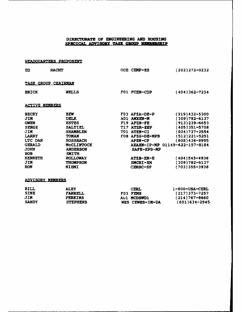
DIRECTORATE OF ENGINEERING AND HOUSINGSPETICA. ADVISORY TAM -G1OP insiT
HEADQUARTERS PROPONENT
ED RACHT OCE CEMP-ES (202)272-0232
TASK GROUP CHAIRMAN
BRICK WELLS F01 FCEN-CDP (404)362-7234
ACTIVE MEMBERS
BECKY BEW F03 AFZA-DE-P (919)432-5300JIM DELK A01 AMXEN-M (309)782-6137OWEN ESTES F19 AFZN-FE (913)239-6653SERGE SALTIEL T17 ATZR-EEP (405)351-5708JIM SHAMBLEN TO1 ATEN-CI (804)727-2554LARRY TOMAN F08 AFZG-DE-MPB (512)221-5251LTC DAN ROSSBACH APEN-CP (808)438-8995GERALD McCLINTOCK AEAEN-IP-MP 01149-622-157-8184JOHN ANDERSON EAFE-EPS-MPBOB SMITHKENNETH HOLLOWAY ATZB-EN-E (404)545-4936JIM THOMPSON SMCRI-EH (309)782-6137RON NIENI CEHSC-SP (703)355-3938
ADVISORY MEMBERS
BILL ALEY CERL 1-800-USA-CERLSINE FARRELL F03 FENS (217)373-7257JIM PERKINS AU1 MCDSWD1 (214)767-8660SANDY STEPHENS WES CEWES-IN-DA (601)634-2945